3 knowledge of different roofing systems in the ... · 14500 13500 . knowledge of different roofing...
TRANSCRIPT

J. Civil Eng. Architect. Res. Vol. 2, No. 4, 2015, pp. 593-604 Received: February 28, 2015; Published: April 25, 2015
Journal of Civil Engineering
and Architecture Research
Knowledge of Different Roofing Systems in the Politecnico di Milano: Geometric Survey and Material Investigation
Francesco Augelli1, Anna Anzani2, Lorenzo Cantini3, Paola Condoleo4, Antonia Gobbo2 and Roberta Mastropirro1
1. Department of Architecture and Urban Studies, Politecnico di Milano, Milan 20158, Italy
2. Department of Design, Politecnico di Milano, Milan 20158, Italy
3. Department of Architecture, Built Environment and Construction Engineering, Politecnico di Milano, Milan 20133, Italy
4. Department of Civil and Environmental Engineering, Politecnico di Milano, Milan 20133, Italy
Corresponding author: Francesco Augelli ([email protected])
Abstract: The paper presents a study carried out on the roofing system of Politecnico di Milano main Campus, a public complex that was built at early XX century and is a relevant part of a valuable architectural heritage. The research was aimed at its structural and health assessment as a first step for designing its subsequent safeguard intervention. The adopted method of analysis consisted of different phases that started from a photographic and 3D direct geometric survey of the trusses that span over large rooms and sometimes bear brickwork vaults hanging below. Material, morphological and constructive aspects of the roofing systems were analyzed also comparing the different building solutions adopted in the different parts of the construction; a recognition of the types of connections between the hanging devices and timber trusses was carried out as well. According to the current Technical Codes, direct inspection of the structural elements was performed in order to collect the following information: macroscopic determination of the timber species, determination of their natural durability, individuation and technological evaluation of the principal defects and alterations, individuation of the pre-existing or still present macroscopic pathologies, sample detection of the ambient conditions and of the timber humidity through non-destructive measurement by electronic thermo-hygrometer. Where needed, drilling tests were applied in the deteriorated or suspected zones and an estimate of the residual sections was achieved, as well as the identification of two different use classes. Considerations on the reliability and recoverability of the inspected timber components were then made possible. Key words: Roofing systems, timber trusses, connection devices, material pathology, diagnostic techniques, rot fungi attack, drilling tests, preservation.
1. Introduction
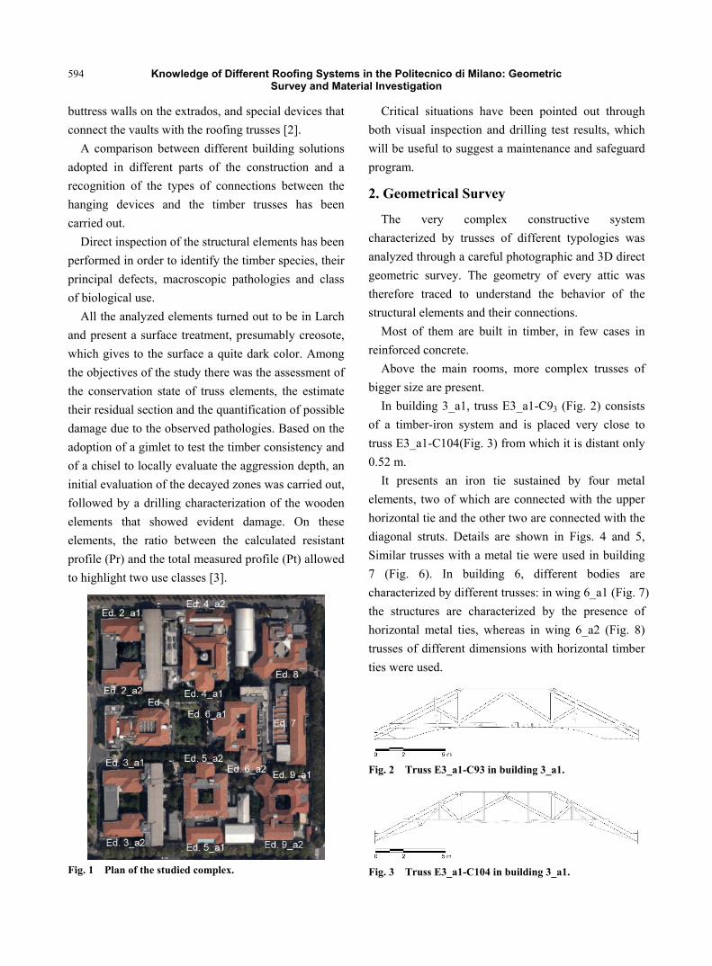
An articulated procedure has been applied for the
structural and health assessment of the roofing
systems of Politecnico di Milano main Campus (Fig.
1), a public complex built at the beginning of the XX
century. The research was aimed to designing a
detailed program of maintenance and safeguard of a
relevant part of a valuable architectural heritage.
The very complex constructive system characterized
by trusses of different typologies spanning over large
rooms was analyzed through a careful photographic
and 3D direct geometric survey [1].
Most of the trusses were built in timber, in few
cases in reinforced concrete. Above the main rooms,
more complex trusses of bigger size are present. In
many cases, the timber trusses are bearing extremely
deformable brickwork vaulted structures hanging
below. They are characterized by a nearly flat central
sector, supported by iron beams, the presence of
Knowledge of Different Roofing Systems in the Politecnico di Milano: Geometric Survey and Material Investigation
594
buttress walls on the extrados, and special devices that
connect the vaults with the roofing trusses [2].
A comparison between different building solutions
adopted in different parts of the construction and a
recognition of the types of connections between the
hanging devices and the timber trusses has been
carried out.
Direct inspection of the structural elements has been
performed in order to identify the timber species, their
principal defects, macroscopic pathologies and class
of biological use.
All the analyzed elements turned out to be in Larch
and present a surface treatment, presumably creosote,
which gives to the surface a quite dark color. Among
the objectives of the study there was the assessment of
the conservation state of truss elements, the estimate
their residual section and the quantification of possible
damage due to the observed pathologies. Based on the
adoption of a gimlet to test the timber consistency and
of a chisel to locally evaluate the aggression depth, an
initial evaluation of the decayed zones was carried out,
followed by a drilling characterization of the wooden
elements that showed evident damage. On these
elements, the ratio between the calculated resistant
profile (Pr) and the total measured profile (Pt) allowed
to highlight two use classes [3].
Fig. 1 Plan of the studied complex.
Critical situations have been pointed out through
both visual inspection and drilling test results, which
will be useful to suggest a maintenance and safeguard
program.
2. Geometrical Survey
The very complex constructive system
characterized by trusses of different typologies was
analyzed through a careful photographic and 3D direct
geometric survey. The geometry of every attic was
therefore traced to understand the behavior of the
structural elements and their connections.
Most of them are built in timber, in few cases in
reinforced concrete.
Above the main rooms, more complex trusses of
bigger size are present.
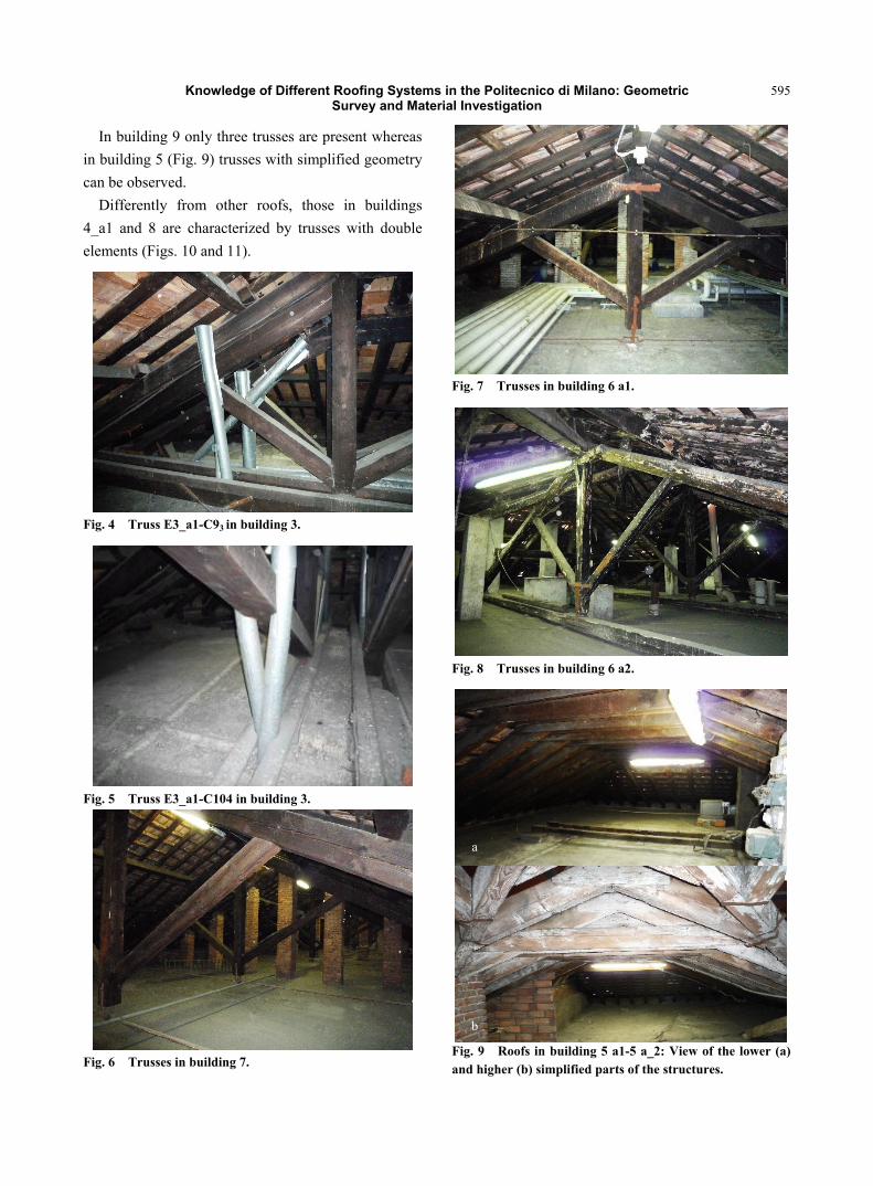
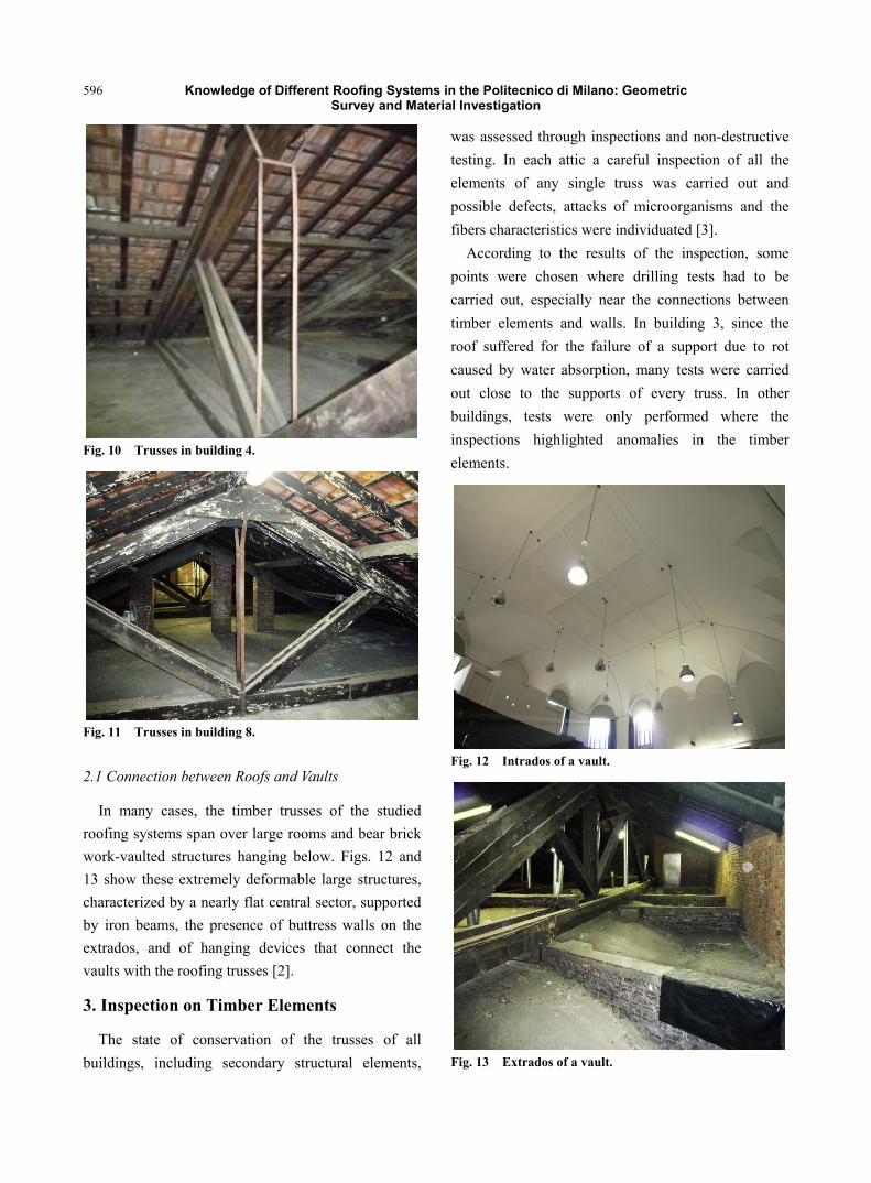
In building 3_a1, truss E3_a1-C93 (Fig. 2) consists
of a timber-iron system and is placed very close to
truss E3_a1-C104(Fig. 3) from which it is distant only
0.52 m.
It presents an iron tie sustained by four metal
elements, two of which are connected with the upper
horizontal tie and the other two are connected with the
diagonal struts. Details are shown in Figs. 4 and 5,
Similar trusses with a metal tie were used in building
7 (Fig. 6). In building 6, different bodies are
characterized by different trusses: in wing 6_a1 (Fig. 7)
the structures are characterized by the presence of
horizontal metal ties, whereas in wing 6_a2 (Fig. 8)
trusses of different dimensions with horizontal timber
ties were used.
Fig. 2 Truss E3_a1-C93 in building 3_a1.
Fig. 3 Truss E3_a1-C104 in building 3_a1.
Knowledge of Different Roofing Systems in the Politecnico di Milano: Geometric Survey and Material Investigation
595
In building 9 only three trusses are present whereas
in building 5 (Fig. 9) trusses with simplified geometry
can be observed.
Differently from other roofs, those in buildings
4_a1 and 8 are characterized by trusses with double
elements (Figs. 10 and 11).
Fig. 4 Truss E3_a1-C93 in building 3.
Fig. 5 Truss E3_a1-C104 in building 3.
Fig. 6 Trusses in building 7.
Fig. 7 Trusses in building 6 a1.
Fig. 8 Trusses in building 6 a2.
Fig. 9 Roofs in building 5 a1-5 a_2: View of the lower (a) and higher (b) simplified parts of the structures.
b
a
Knowledge of Different Roofing Systems in the Politecnico di Milano: Geometric Survey and Material Investigation
596
Fig. 10 Trusses in building 4.
Fig. 11 Trusses in building 8.
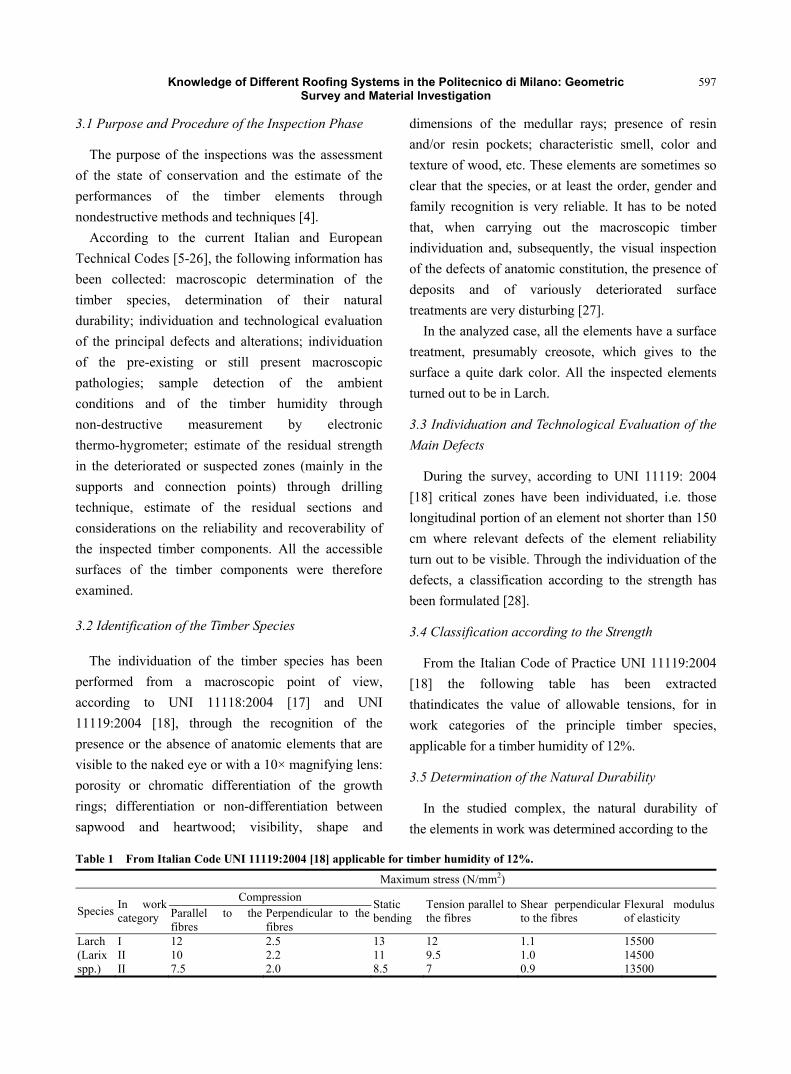
2.1 Connection between Roofs and Vaults
In many cases, the timber trusses of the studied
roofing systems span over large rooms and bear brick
work-vaulted structures hanging below. Figs. 12 and
13 show these extremely deformable large structures,
characterized by a nearly flat central sector, supported
by iron beams, the presence of buttress walls on the
extrados, and of hanging devices that connect the
vaults with the roofing trusses [2].
3. Inspection on Timber Elements
The state of conservation of the trusses of all
buildings, including secondary structural elements,
was assessed through inspections and non-destructive
testing. In each attic a careful inspection of all the
elements of any single truss was carried out and
possible defects, attacks of microorganisms and the
fibers characteristics were individuated [3].
According to the results of the inspection, some
points were chosen where drilling tests had to be
carried out, especially near the connections between
timber elements and walls. In building 3, since the
roof suffered for the failure of a support due to rot
caused by water absorption, many tests were carried
out close to the supports of every truss. In other
buildings, tests were only performed where the
inspections highlighted anomalies in the timber
elements.
Fig. 12 Intrados of a vault.
Fig. 13 Extrados of a vault.
Knowledge of Different Roofing Systems in the Politecnico di Milano: Geometric Survey and Material Investigation
597
3.1 Purpose and Procedure of the Inspection Phase
The purpose of the inspections was the assessment
of the state of conservation and the estimate of the
performances of the timber elements through
nondestructive methods and techniques [4].
According to the current Italian and European
Technical Codes [5-26], the following information has
been collected: macroscopic determination of the
timber species, determination of their natural
durability; individuation and technological evaluation
of the principal defects and alterations; individuation
of the pre-existing or still present macroscopic
pathologies; sample detection of the ambient
conditions and of the timber humidity through
non-destructive measurement by electronic
thermo-hygrometer; estimate of the residual strength
in the deteriorated or suspected zones (mainly in the
supports and connection points) through drilling
technique, estimate of the residual sections and
considerations on the reliability and recoverability of
the inspected timber components. All the accessible
surfaces of the timber components were therefore
examined.
3.2 Identification of the Timber Species
The individuation of the timber species has been
performed from a macroscopic point of view,
according to UNI 11118:2004 [17] and UNI
11119:2004 [18], through the recognition of the
presence or the absence of anatomic elements that are
visible to the naked eye or with a 10× magnifying lens:
porosity or chromatic differentiation of the growth
rings; differentiation or non-differentiation between
sapwood and heartwood; visibility, shape and
dimensions of the medullar rays; presence of resin
and/or resin pockets; characteristic smell, color and
texture of wood, etc. These elements are sometimes so
clear that the species, or at least the order, gender and
family recognition is very reliable. It has to be noted
that, when carrying out the macroscopic timber
individuation and, subsequently, the visual inspection
of the defects of anatomic constitution, the presence of
deposits and of variously deteriorated surface
treatments are very disturbing [27].
In the analyzed case, all the elements have a surface
treatment, presumably creosote, which gives to the
surface a quite dark color. All the inspected elements
turned out to be in Larch.
3.3 Individuation and Technological Evaluation of the
Main Defects
During the survey, according to UNI 11119: 2004
[18] critical zones have been individuated, i.e. those
longitudinal portion of an element not shorter than 150
cm where relevant defects of the element reliability
turn out to be visible. Through the individuation of the
defects, a classification according to the strength has
been formulated [28].
3.4 Classification according to the Strength
From the Italian Code of Practice UNI 11119:2004
[18] the following table has been extracted
thatindicates the value of allowable tensions, for in
work categories of the principle timber species,
applicable for a timber humidity of 12%.
3.5 Determination of the Natural Durability
In the studied complex, the natural durability of
the elements in work was determined according to the
Table 1 From Italian Code UNI 11119:2004 [18] applicable for timber humidity of 12%.
Maximum stress (N/mm2)
Species In work category
Compression Static bending
Tension parallel to the fibres
Shear perpendicular to the fibres
Flexural modulus of elasticity Parallel to the
fibres Perpendicular to the fibres
Larch (Larix spp.)
I II II
12 10 7.5
2.5 2.2 2.0
13 11 8.5
12 9.5 7
1.1 1.0 0.9
15500 14500 13500
Knowledge of Different Roofing Systems in the Politecnico di Milano: Geometric Survey and Material Investigation
598
Italian Code UNI EN 335-1:2006 [7] and UNI EN
335-2: 2006 [8]. In the case of Larch it is as follows:
Moderately durable to the fungi rot attacks; not
resistant to the attacks by wood borers beetles
(Anobium punctatum and Hylotrupes bajulus).
3.6 Individuation of Present and Previous
Macroscopic Pathologies
Besides the assessment of the conservation state of
single truss elements (primary and secondary struts and
ties) and the estimate of their residual section, main
objective of the study was also to inspect, where
possible, the structural nodes between main struts and
main ties close to the connection to the walls and to
quantify possible damage due to the observed
pathologies. Also in this case the codes UNI
11119:2004 [18] and UNI 11130:2004 [26] were
followed. On the structural nodes, where the
macroscopic examination let one suspect the presence
of current or previous infections but was not sufficient
to achieve a complete diagnosis, as well as on each
accessible wall support, preliminary beating tests were
performed, aimed at detect fungi attacks [27]. For an
initial evaluation and to quantify the decayed zones, a
gimlet to test the timber consistency and a chisel to
locally evaluate the depth of the aggression were
adopted. The results of this phase were determinant for
the subsequent choice of the points where drilling test
were required [28].
In the cases where significant biological decay was
detected, the assumed load-bearing section was
conveniently reduced with respect to the real geometry.
In particular, it has to be noted that in building 3 on
struts of truss E3_a1-C115 corresponding to the East
masonry support and on strut E3_a1-FP10 a severe
fungi attack was detected.
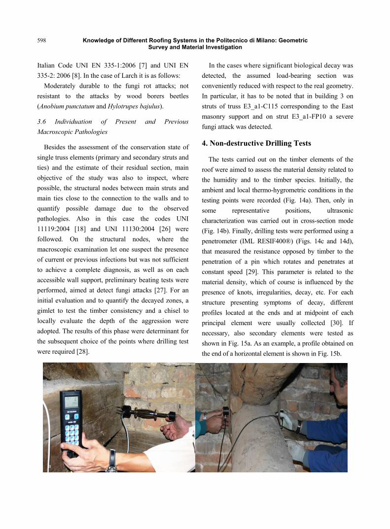
4. Non-destructive Drilling Tests
The tests carried out on the timber elements of the
roof were aimed to assess the material density related to
the humidity and to the timber species. Initially, the
ambient and local thermo-hygrometric conditions in the
testing points were recorded (Fig. 14a). Then, only in
some representative positions, ultrasonic
characterization was carried out in cross-section mode
(Fig. 14b). Finally, drilling tests were performed using a
penetrometer (IML RESIF400®) (Figs. 14c and 14d),
that measured the resistance opposed by timber to the
penetration of a pin which rotates and penetrates at
constant speed [29]. This parameter is related to the
material density, which of course is influenced by the
presence of knots, irregularities, decay, etc. For each
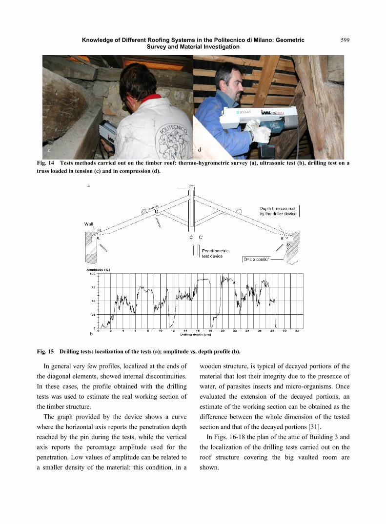
structure presenting symptoms of decay, different
profiles located at the ends and at midpoint of each
principal element were usually collected [30]. If
necessary, also secondary elements were tested as
shown in Fig. 15a. As an example, a profile obtained on
the end of a horizontal element is shown in Fig. 15b.
ba
Knowledge of Different Roofing Systems in the Politecnico di Milano: Geometric Survey and Material Investigation
599
Fig. 14 Tests methods carried out on the timber roof: thermo-hygrometric survey (a), ultrasonic test (b), drilling test on a truss loaded in tension (c) and in compression (d).
Fig. 15 Drilling tests: localization of the tests (a); amplitude vs. depth profile (b).
In general very few profiles, localized at the ends of
the diagonal elements, showed internal discontinuities.
In these cases, the profile obtained with the drilling
tests was used to estimate the real working section of
the timber structure.
The graph provided by the device shows a curve
where the horizontal axis reports the penetration depth
reached by the pin during the tests, while the vertical
axis reports the percentage amplitude used for the
penetration. Low values of amplitude can be related to
a smaller density of the material: this condition, in a
wooden structure, is typical of decayed portions of the
material that lost their integrity due to the presence of
water, of parasites insects and micro-organisms. Once
evaluated the extension of the decayed portions, an
estimate of the working section can be obtained as the
difference between the whole dimension of the tested
section and that of the decayed portions [31].
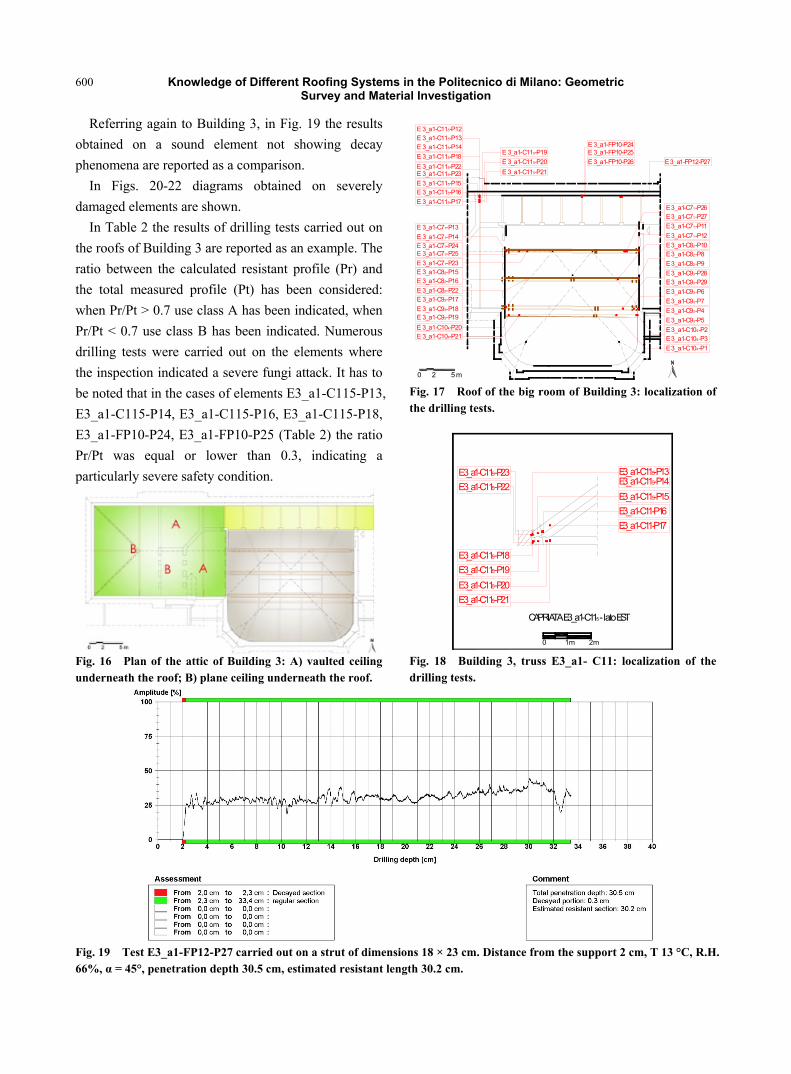
In Figs. 16-18 the plan of the attic of Building 3 and
the localization of the drilling tests carried out on the
roof structure covering the big vaulted room are
shown.
dc
b
a
Knowledge of Different Roofing Systems in the Politecnico di Milano: Geometric Survey and Material Investigation
600
Referring again to Building 3, in Fig. 19 the results
obtained on a sound element not showing decay
phenomena are reported as a comparison.
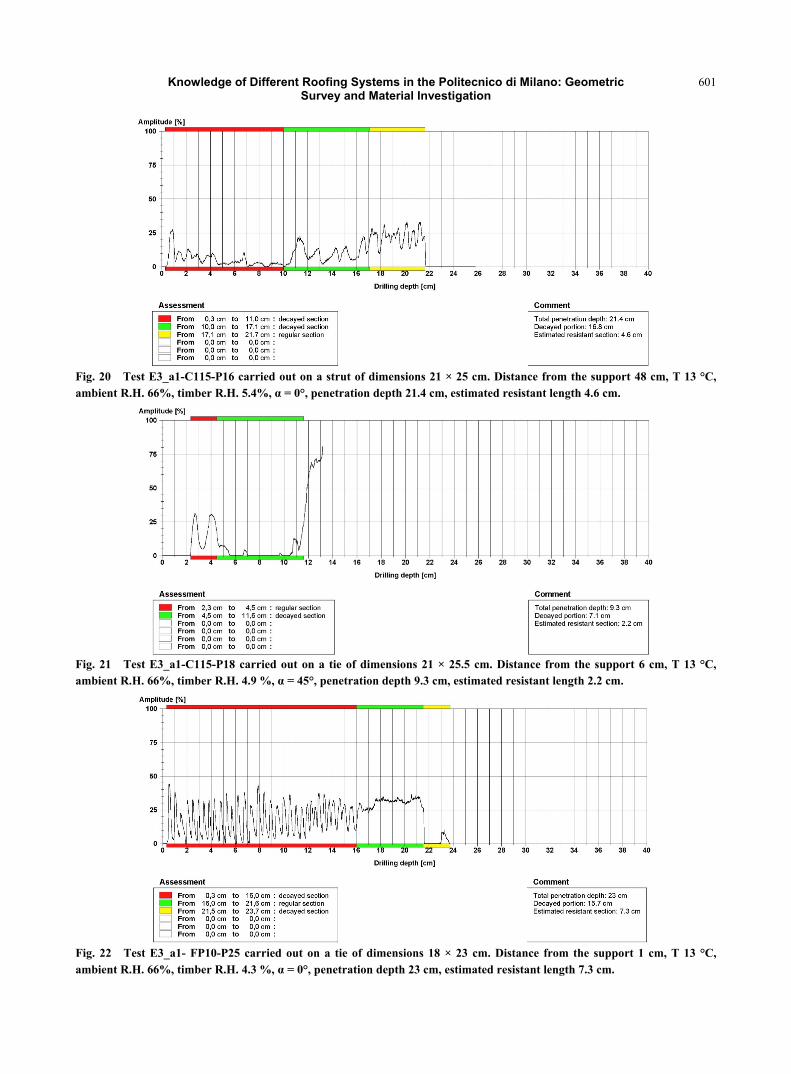
In Figs. 20-22 diagrams obtained on severely
damaged elements are shown.
In Table 2 the results of drilling tests carried out on
the roofs of Building 3 are reported as an example. The
ratio between the calculated resistant profile (Pr) and
the total measured profile (Pt) has been considered:
when Pr/Pt > 0.7 use class A has been indicated, when
Pr/Pt < 0.7 use class B has been indicated. Numerous
drilling tests were carried out on the elements where
the inspection indicated a severe fungi attack. It has to
be noted that in the cases of elements E3_a1-C115-P13,
E3_a1-C115-P14, E3_a1-C115-P16, E3_a1-C115-P18,
E3_a1-FP10-P24, E3_a1-FP10-P25 (Table 2) the ratio
Pr/Pt was equal or lower than 0.3, indicating a
particularly severe safety condition.
Fig. 16 Plan of the attic of Building 3: A) vaulted ceiling underneath the roof; B) plane ceiling underneath the roof.
2 5 m0
E 3_a1-C71-P11
E 3_a1-C71-P12
E 3_a1-C82-P10E 3_a1-C82-P8
E 3_a1-C82-P9
E 3_a1-C93-P28E 3_a1-C93-P29
E 3_a1-C93-P4
E 3_a1-C93-P5
E 3_a1-C104-P2E 3_a1-C104-P3
E 3_a1-C104-P1
E 3_a1-C71-P13
E 3_a1-C71-P14E 3_a1-C71-P24
E 3_a1-C71-P23E 3_a1-C82-P15E 3_a1-C82-P16
E 3_a1-C82-P22E 3_a1-C93-P17
E 3_a1-C93-P18E 3_a1-C93-P19
E 3_a1-C104-P20E 3_a1-C104-P21
E 3_a1-FP12-P27E 3_a1-FP10-P26
E 3_a1-FP10-P24E 3_a1-FP10-P25E 3_a1-C115-P19
E 3_a1-C115-P20
E 3_a1-C115-P21
E 3_a1-C115-P18
E 3_a1-C115-P22
E 3_a1-C115-P15
E 3_a1-C115-P23
E 3_a1-C115-P16
E 3_a1-C115-P17
E 3_a1-C115-P12E 3_a1-C115-P13E 3_a1-C115-P14
E 3_a1-C71-P25
E 3_a1-C71-P26E 3_a1-C71-P27
E 3_a1-C93-P6
E 3_a1-C93-P7
Fig. 17 Roof of the big room of Building 3: localization of the drilling tests.
CAPRIATA E3_a1-C115 - lato EST
0 1 m 2 m
E3_a1-C11-P17
E3_a1-C11-P16
E3_a1-C115-P15
E3_a1-C115-P14E3_a1-C115-P13
E3_a1-C115-P22
E3_a1-C115-P23
E3_a1-C115-P19
E3_a1-C115-P18
E3_a1-C115-P20
E3_a1-C115-P21
Fig. 18 Building 3, truss E3_a1- C11: localization of the drilling tests.
Fig. 19 Test E3_a1-FP12-P27 carried out on a strut of dimensions 18 × 23 cm. Distance from the support 2 cm, T 13 °C, R.H. 66%, α = 45°, penetration depth 30.5 cm, estimated resistant length 30.2 cm.
Knowledge of Different Roofing Systems in the Politecnico di Milano: Geometric Survey and Material Investigation
601
Fig. 20 Test E3_a1-C115-P16 carried out on a strut of dimensions 21 × 25 cm. Distance from the support 48 cm, T 13 °C, ambient R.H. 66%, timber R.H. 5.4%, α = 0°, penetration depth 21.4 cm, estimated resistant length 4.6 cm.
Fig. 21 Test E3_a1-C115-P18 carried out on a tie of dimensions 21 × 25.5 cm. Distance from the support 6 cm, T 13 °C, ambient R.H. 66%, timber R.H. 4.9 %, α = 45°, penetration depth 9.3 cm, estimated resistant length 2.2 cm.
Fig. 22 Test E3_a1- FP10-P25 carried out on a tie of dimensions 18 × 23 cm. Distance from the support 1 cm, T 13 °C, ambient R.H. 66%, timber R.H. 4.3 %, α = 0°, penetration depth 23 cm, estimated resistant length 7.3 cm.
Knowledge of Different Roofing Systems in the Politecnico di Milano: Geometric Survey and Material Investigation
602
Table 2 Example of use class estimate carried out on the roof of Building 3.
Test denominated Angle α Pt (cm) Pr (cm) Pr/Pt Use class
E3_a1- C71-P26 45° 27.0 27.0 1 A
E3_a1- C71-P14 45° 28.4 24.7 0.86 A
E3_a1- C93-P29 0° 24.3 16.8 0.69 B
E3_a1- C93-P19 45° 28.23 18.3 0.64 B
E3_a1-FP10-P26 0° 23 15.3 0.66 B
E3_a1- C93-P28 0° 24.67 22.67 0.91 A
E3_a1-FP12-P27 45° 30.5 30.2 0.99 A
α = angle between the penetration trajectory and the horizontal direction; Pt = penetration depth; Pr = estimated resistant profile obtainedby subtraction from Pt of the decayed portions identified by the results of drilling test; Use class A: Pr/Pt> 0.7; Use classB: Pr/Pt< 0.7.
5. Conclusions
An articulated procedure has been applied for the
structural and health assessment of the roofing
systems of Politecnico di Milano main Campus, a
public complex built at the beginning of XX century.
The research was aimed to designing a safeguard
intervention of a relevant part of a valuable
architectural heritage [30]. Direct inspection of the
structural elements allowed to identify the timber
species, their principal defects, macroscopic
pathologies and class of biological use. Where needed,
drilling characterization of the wooden elements with
evidence of damage was carried out and the ratio
between the calculated resistant profile (Pr) and the
total measured profile (Pt) allowed to highlight two
use classes.
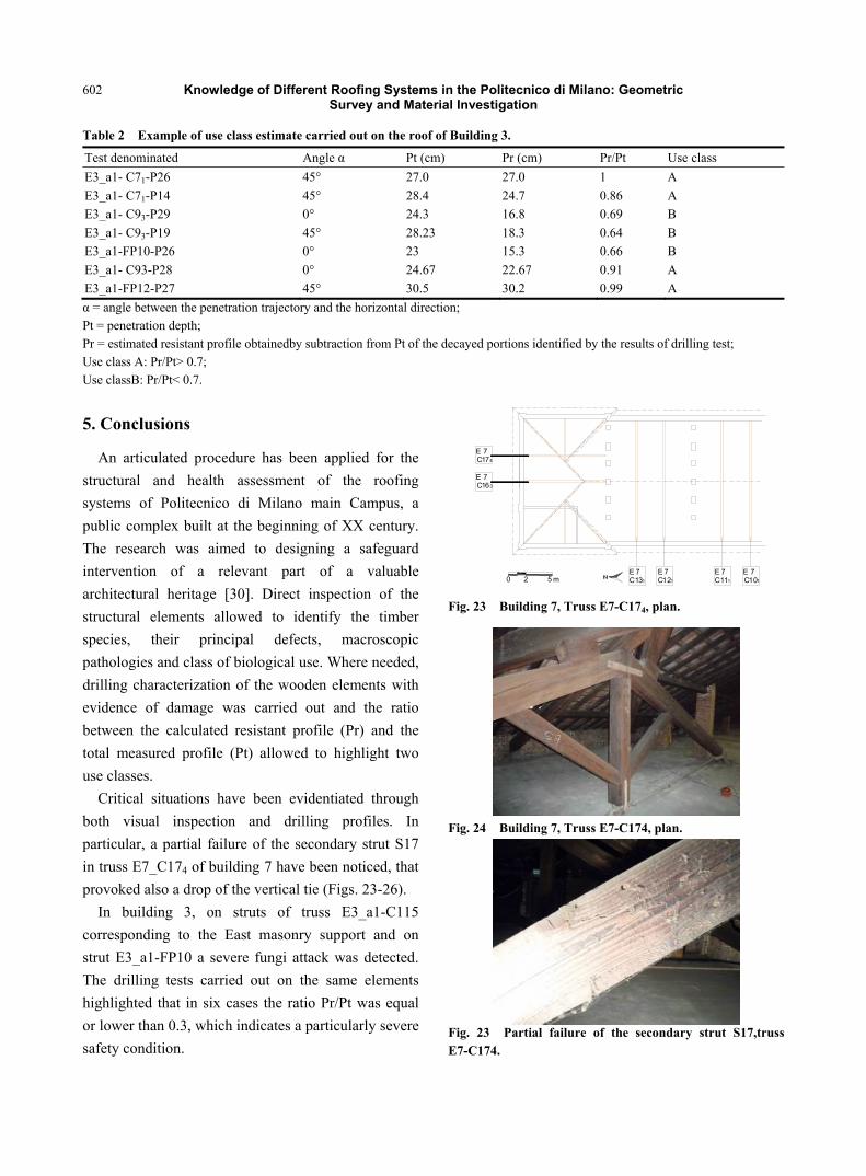
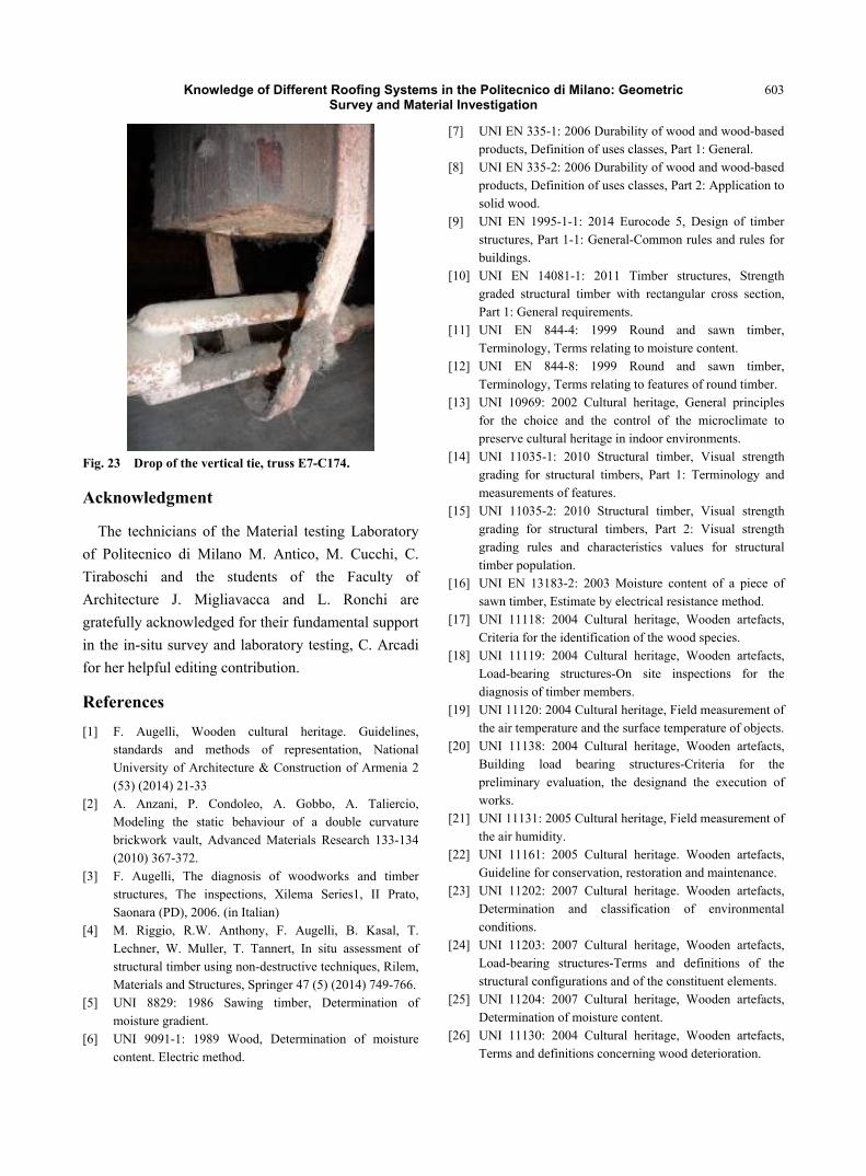
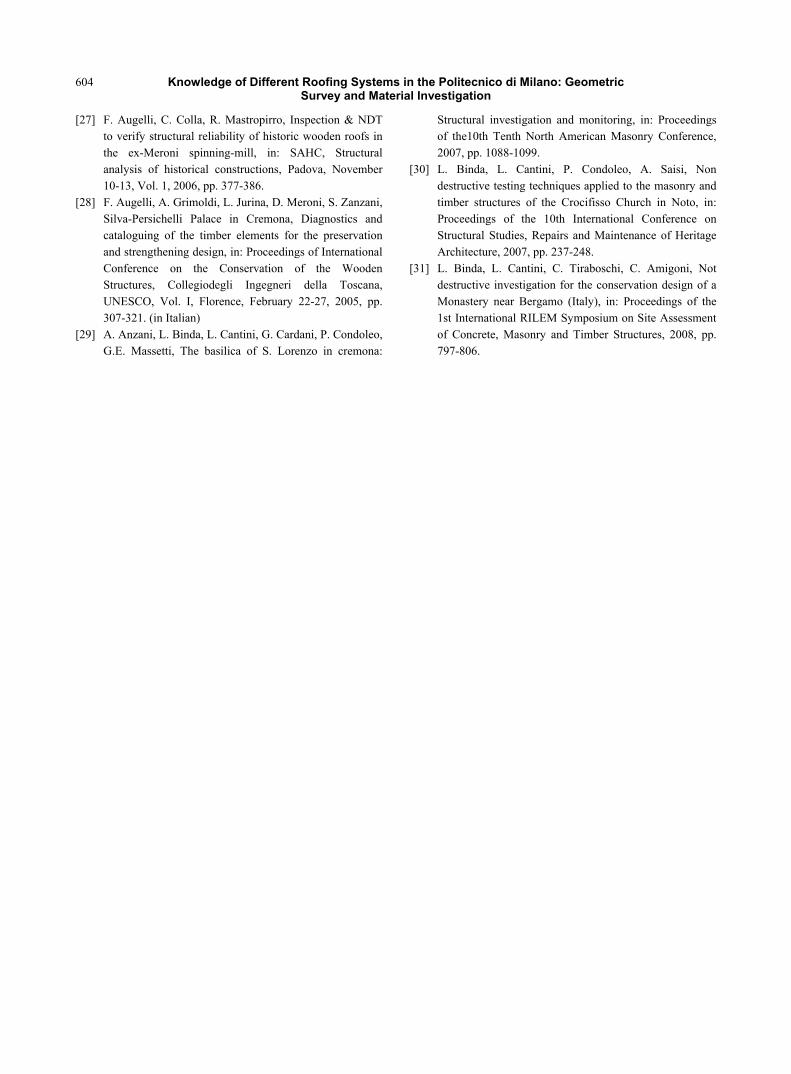
Critical situations have been evidentiated through
both visual inspection and drilling profiles. In
particular, a partial failure of the secondary strut S17
in truss E7_C174 of building 7 have been noticed, that
provoked also a drop of the vertical tie (Figs. 23-26).
In building 3, on struts of truss E3_a1-C115
corresponding to the East masonry support and on
strut E3_a1-FP10 a severe fungi attack was detected.
The drilling tests carried out on the same elements
highlighted that in six cases the ratio Pr/Pt was equal
or lower than 0.3, which indicates a particularly severe
safety condition.
E 7C101
E 7C111
E 7C121
E 7C131
E 7C163
E 7C174
2 5 m0
Fig. 23 Building 7, Truss E7-C174, plan.
Fig. 24 Building 7, Truss E7-C174, plan.
Fig. 23 Partial failure of the secondary strut S17,truss E7-C174.
Knowledge of Different Roofing Systems in the Politecnico di Milano: Geometric Survey and Material Investigation
603
Fig. 23 Drop of the vertical tie, truss E7-C174.
Acknowledgment
The technicians of the Material testing Laboratory
of Politecnico di Milano M. Antico, M. Cucchi, C.
Tiraboschi and the students of the Faculty of
Architecture J. Migliavacca and L. Ronchi are
gratefully acknowledged for their fundamental support
in the in-situ survey and laboratory testing, C. Arcadi
for her helpful editing contribution.
References
[1] F. Augelli, Wooden cultural heritage. Guidelines, standards and methods of representation, National University of Architecture & Construction of Armenia 2 (53) (2014) 21-33
[2] A. Anzani, P. Condoleo, A. Gobbo, A. Taliercio, Modeling the static behaviour of a double curvature brickwork vault, Advanced Materials Research 133-134 (2010) 367-372.
[3] F. Augelli, The diagnosis of woodworks and timber structures, The inspections, Xilema Series1, II Prato, Saonara (PD), 2006. (in Italian)
[4] M. Riggio, R.W. Anthony, F. Augelli, B. Kasal, T. Lechner, W. Muller, T. Tannert, In situ assessment of structural timber using non-destructive techniques, Rilem, Materials and Structures, Springer 47 (5) (2014) 749-766.
[5] UNI 8829: 1986 Sawing timber, Determination of moisture gradient.
[6] UNI 9091-1: 1989 Wood, Determination of moisture content. Electric method.
[7] UNI EN 335-1: 2006 Durability of wood and wood-based products, Definition of uses classes, Part 1: General.
[8] UNI EN 335-2: 2006 Durability of wood and wood-based products, Definition of uses classes, Part 2: Application to solid wood.
[9] UNI EN 1995-1-1: 2014 Eurocode 5, Design of timber structures, Part 1-1: General-Common rules and rules for buildings.
[10] UNI EN 14081-1: 2011 Timber structures, Strength graded structural timber with rectangular cross section, Part 1: General requirements.
[11] UNI EN 844-4: 1999 Round and sawn timber, Terminology, Terms relating to moisture content.
[12] UNI EN 844-8: 1999 Round and sawn timber, Terminology, Terms relating to features of round timber.
[13] UNI 10969: 2002 Cultural heritage, General principles for the choice and the control of the microclimate to preserve cultural heritage in indoor environments.
[14] UNI 11035-1: 2010 Structural timber, Visual strength grading for structural timbers, Part 1: Terminology and measurements of features.
[15] UNI 11035-2: 2010 Structural timber, Visual strength grading for structural timbers, Part 2: Visual strength grading rules and characteristics values for structural timber population.
[16] UNI EN 13183-2: 2003 Moisture content of a piece of sawn timber, Estimate by electrical resistance method.
[17] UNI 11118: 2004 Cultural heritage, Wooden artefacts, Criteria for the identification of the wood species.
[18] UNI 11119: 2004 Cultural heritage, Wooden artefacts, Load-bearing structures-On site inspections for the diagnosis of timber members.
[19] UNI 11120: 2004 Cultural heritage, Field measurement of the air temperature and the surface temperature of objects.
[20] UNI 11138: 2004 Cultural heritage, Wooden artefacts, Building load bearing structures-Criteria for the preliminary evaluation, the designand the execution of works.
[21] UNI 11131: 2005 Cultural heritage, Field measurement of the air humidity.
[22] UNI 11161: 2005 Cultural heritage. Wooden artefacts, Guideline for conservation, restoration and maintenance.
[23] UNI 11202: 2007 Cultural heritage. Wooden artefacts, Determination and classification of environmental conditions.
[24] UNI 11203: 2007 Cultural heritage, Wooden artefacts, Load-bearing structures-Terms and definitions of the structural configurations and of the constituent elements.
[25] UNI 11204: 2007 Cultural heritage, Wooden artefacts, Determination of moisture content.
[26] UNI 11130: 2004 Cultural heritage, Wooden artefacts, Terms and definitions concerning wood deterioration.
Knowledge of Different Roofing Systems in the Politecnico di Milano: Geometric Survey and Material Investigation
604
[27] F. Augelli, C. Colla, R. Mastropirro, Inspection & NDT to verify structural reliability of historic wooden roofs in the ex-Meroni spinning-mill, in: SAHC, Structural analysis of historical constructions, Padova, November 10-13, Vol. 1, 2006, pp. 377-386.
[28] F. Augelli, A. Grimoldi, L. Jurina, D. Meroni, S. Zanzani, Silva-Persichelli Palace in Cremona, Diagnostics and cataloguing of the timber elements for the preservation and strengthening design, in: Proceedings of International Conference on the Conservation of the Wooden Structures, Collegiodegli Ingegneri della Toscana, UNESCO, Vol. I, Florence, February 22-27, 2005, pp. 307-321. (in Italian)
[29] A. Anzani, L. Binda, L. Cantini, G. Cardani, P. Condoleo, G.E. Massetti, The basilica of S. Lorenzo in cremona:
Structural investigation and monitoring, in: Proceedings of the10th Tenth North American Masonry Conference, 2007, pp. 1088-1099.
[30] L. Binda, L. Cantini, P. Condoleo, A. Saisi, Non destructive testing techniques applied to the masonry and timber structures of the Crocifisso Church in Noto, in: Proceedings of the 10th International Conference on Structural Studies, Repairs and Maintenance of Heritage Architecture, 2007, pp. 237-248.
[31] L. Binda, L. Cantini, C. Tiraboschi, C. Amigoni, Not destructive investigation for the conservation design of a Monastery near Bergamo (Italy), in: Proceedings of the 1st International RILEM Symposium on Site Assessment of Concrete, Masonry and Timber Structures, 2008, pp. 797-806.