3 image quality repair analysis procedures docuprint n2025/n2825 3-5 solid area density, background...
TRANSCRIPT

02/20003-1DocuPrint N2025/N2825
Image Quality Repair Analysis ProceduresInitial Issue
3 Image Quality Repair Analysis ProceduresIntroduction ..................................................................................................................... 3-3Image Quality Defect Definitions..................................................................................... 3-3Image Quality Checkout.................................................................................................. 3-4Solid Area Density........................................................................................................... 3-5Background ..................................................................................................................... 3-5Deletions (Line, Band, Spots) ......................................................................................... 3-6Fusing ............................................................................................................................. 3-6Resolution ....................................................................................................................... 3-7Registration (Side to Side) .............................................................................................. 3-7Registration (Lead Edge to Trail Edge)........................................................................... 3-8Skew ............................................................................................................................... 3-8Skips / Smears ................................................................................................................ 3-9Spots ............................................................................................................................... 3-9Other Print Defects.......................................................................................................... 3-10IQ RAP 1 Light (Undertoned) Prints................................................................................ 3-10IQ RAP 2 Blank Prints..................................................................................................... 3-11IQ RAP 3 Spots............................................................................................................... 3-12IQ RAP 4 Horizontal (Scan) Deletions ............................................................................ 3-13IQ RAP 5 Vertical (Process) Deletions............................................................................ 3-14IQ RAP 6 Spot Deletions................................................................................................. 3-15IQ RAP 7 Vertical (Process) Streaks .............................................................................. 3-16IQ RAP 8 Horizontal (Scan) Streaks ............................................................................... 3-17IQ RAP 9 Residual Image ............................................................................................... 3-18IQ RAP 10 Black Prints ................................................................................................... 3-19IQ RAP 11 Background................................................................................................... 3-20IQ RAP 12 Uneven Density............................................................................................. 3-21IQ RAP 13 Skewed Image .............................................................................................. 3-22IQ RAP 14 Damaged Print .............................................................................................. 3-23IQ RAP 15 Registration................................................................................................... 3-24IQ RAP 16 Skips / Smears.............................................................................................. 3-25IQ RAP 17 Unfused Image.............................................................................................. 3-25IQ RAP 18 Resolution ..................................................................................................... 3-26

02/2
000
3-2
Doc
uPrin
t N20
25/N
2825
Initi
al Is
sue
Imag
e Q
ualit
y R
epai
r A
naly
sis
Pro
cedu
res

age Quality Defect DefinitionsImage Quality Repair Analysis Procedures
Introduction Image Quality Defect Definitions evaluate each of the print quality parameters. Each quality parameter. The areas and the print qualityckout.
ality Defect Definitions
Go To:
is too light. IQ RAP 1
ge. IQ RAP 2
ge. IQ RAP 3
as of the image that are extremely orizontally across the page in the
IQ RAP 4
of the image that are extremely ertically along the page in the
IQ RAP 5
d with irregular white areas. IQ RAP 6
es/bands in the process direction. IQ RAP 7
lines/bands in the direction of IQ RAP 8
evious print, which was not been developed on the current
IQ RAP 9
vered with toner and has no visi- IQ RAP 10
ion in non image areas. Refer to IQ RAP 11
and solid area density image var- IQ RAP 12
f the image from its intended posi- IQ RAP 13
cessive curl, cuts, folds or IQ RAP 14
Displacement of the image, in the n on the print.(inboard to out-irection of scan, from its intended
IQ RAP 15
of the image in bands across the the image in bands across the pro- blurred or compressed.
IQ RAP 16
ge is unfused. Refer to the specifi- IQ RAP 17
nes and halftone patches cannot IQ RAP 18
02/20003-3DocuPrint N2025/N2825 Introduction, Im
Initial Issue
This section contains image quality repair procedures to assist in correcting image qualitydefects. These procedures provide defect samples, definitions and specifications to help iden-tify the type of defect that exists, the test pattern to use, and actions required to correct thedefects.
Throughout these procedures, the term “vertical” refers to the process direction (the directionpaper travels through the printer); the term “horizontal” refers to the scanning direction (thedirection the laser beam scans across the page).
Be sure to check the paper tray to determine whether paper is being fed long edge or shortedge first. This determines “vertical” and “horizontal” for paper fed from that particular tray.
Cleaning procedures should always be performed before beginning any Print Quality Repairprocedure.
Be sure that the paper meets printer specifications. Changing the paper, or using paper from apreviously unopened ream, will resolve many print quality issues.
After resolving an image quality problem, return to Image Quality Checkout to verify that noother image quality defects exist.
Sample reproductions of the various image quality patterns are included under Image QualitySpecifications.
Use the Image Quality RAPS to further diagnose machine problems.
In the Y/N (Yes/No) steps of the RAPs, a Yes response will lead you to the next step. A Noresponse will indicate a corrective action, or will direct you to another step. When the indicatedcorrective action has been completed, go to Section 1 and restart the Initial Actions to verifythat the problem has been corrected.
The System Controller Test Print is used toarea of the test pattern is used for a printparameters are listed in Image Quality Che
Table 1 Image Qu
Defect Definitions
LIGHT PRINTS: The overall image density
BLANK PRINTS: Prints with no visible ima
SPOTS: There are spots of toner on the pa
HORIZONTAL DELETIONS: There are arelight or missing entirely. These areas run hdirection of scanning.
VERTICAL DELETIONS: There are areas light or missing entirely. These areas run vdirection of paper movement.
SPOT DELETIONS: Solid areas are marke
VERTICAL STREAKS: Extraneous dark lin
HORIZONTAL STREAKS: Extraneous darkscan.
RESIDUAL IMAGES: The image from a prremoved during the cleaning process, has print.
BLACK PRINTS: The print is completely coble image.
BACKGROUND: Uniform toner contaminatthe Background specification.
UNEVEN DENSITY: The text/line darknessies across the print.
SKEWED IMAGE: Angular displacement otion on the print. Refer to the specification.
DAMAGED PRINTS: Creases, wrinkles, exembossed marks.
REGISTRATION (lead edge to trail edge): process direction, from its intended positioboard): Displacement of the image, in the dposition on the print.
SKIPS / SMEARS: Skip-Loss or stretchingprocess direction. Smear-The distortion of cess direction that cause it to appear to be
UNFUSED IMAGE: Part of or all of the imacation.
RESOLUTION: At 600 DPI, the two pixel libe reproduced clearly on the print.

DocuPrint N2025/N2825
Initial Issue
Controller Test Print.
02/20003-4Image Quality Checkout
Image Quality Repair Analysis Procedures
Image Quality CheckoutThe System Controller Test Print is used to evaluate and ensure that the printed image meetsthe printer specifications.
Use new paper, whenever possible, to check the image quality of prints. Make five (5) prints ofthe System Controller Test Print (Figure 1) (GP 6.1). Discard the first two prints and retain theremaining prints for image quality analysis.
The Image quality Checkout is used to evaluate the following:
1. Resolution (2 places) (Figure 1)
2. Skips and Smears (4 places) (Figure 1)
3. Registration (1 place) (Figure 1)
4. Resolution and Uniformity (2 places) (Figure 1)
5. Solid Area Density (3 places) (Figure 1)
6. Half Tone Resolution (2 places). (Figure 1)
Go to Solid Area Density.
Figure 1 System

olid Area Density, BackgroundImage Quality Repair Analysis Procedures
Solid Area Density Background
cale (82P284). The worst background area on anyating guide (Figure 1). The print is at the area 3 or
y.
und specification. Go to Deletions.
Rating Guide
02/20003-5DocuPrint N2025/N2825 S
Initial Issue
ProcedureEnsure the printer is set for 600 dpi. Compare the solid areas on the System Controller TestPatterns with the Output Reference document (82P520) (Figure 1). The solid areas on theprint are at the 1.20 density square on the scale or higher, and all the solid areas on anyprint differ in density less than one density square.Y N
The solid area density is uniform.Y N
Go to IQ RAP 12 Uneven Density.
The prints are too faint.Y N
The prints are black.Y N
Go to IQ RAP 11 Background.
Go to IQ RAP 10 Black Prints
Go to IQ RAP 1 Light Prints
The Solid Area Density is within specifications. Go to Background.
Figure 1 Output Reference Document
ProcedureCompare the Test Prints with the Visual Sprint should be at, or below, area 3 on the rbelow.Y N
The background is uniform.Y N
Go to IQ RAP 12 Uneven Densit
Go to IQ RAP 11 Background.
The printed test patterns meet the Backgro
Figure 1

DocuPrint N2025/N2825
Initial Issue
printer is from 41o F (5o Celsius) at 15% relativetive humidity. The fusing performance of the printer
-up time.
ransparency will affect the fusing of prints.
ect on the fusing of prints.
System Controller Test Print (Figure 1). Rub the. The image should not lift off of the surface of the
the specification.
pecification. Go to Resolution.
Fusing Quality.
02/20003-6Deletions, Fusing
Image Quality Repair Analysis Procedures
Deletions (Line, Band, Spots)ProcedureInspect Test Prints for the presence of deletions (missing image). There should be no deletionswith a diameter larger than 0.5 mm visible on test prints (Figure 1). There are deletions onthe test prints.Y N
Go to Fusing.
There are vertical (in direction of paper movement) Line/Band deletions present.Y N
There are Horizontal (in direction of scanning) Line/Band Deletions present.Y N
There are Spot Deletions present.Y N
Go to Fusing.
Go to IQ RAP 6 Spot Deletions.
Go to IQ RAP 4 Horizontal Deletions.
Go to IQ RAP 5 Vertical Deletions.
Figure 1 Line, Band, or Spot Deletions.
FusingProcedure
NOTE: The operating environment of the humidity to 95o F (35o Celsius) at 85% relawill vary according to the environment.
• A cold environment will affect the warm
• The weight (lb. / gsm) of the paper or t
• High humidity will have an adverse aff
Check the fusing quality of the image of aimage three times with a soft cloth or tissueprint. The fusing quality of the image meetsY N
Go to IQ RAP 17 Unfused Image.
The printed test patterns meet the Fusing s
Figure 1

Resolution, RegistrationImage Quality Repair Analysis Procedures
Resolution Registration (Side to Side)
e System Controller Test Patterns. Fold the paper inve the fold line of the paper with reference to the is within +/- 2.0 mm of the target cross hairs
l Edge registration specification. Go to Registration
ration (Side to Side).
02/20003-7DocuPrint N2025/N2825
Initial Issue
ProcedureRefer to Figure 1. Observe the three image areas on several System Controller Test Patterns.Check the resolution of the images in each of the areas:Arrow 1The two pixel vertical, horizontal and diagonal lines should be clear and continuous. The diag-onal lines might appear to be narrower than the others.Arrow 2The text paragraphs should be roughly equal in density.Arrow 3The half-tone patches adjacent to the solid blocks in the corners should be uniform in appear-ance. The three checks (arrows 1, 2, & 3) are within specification.Y N
Go to IQ RAP 18 Resolution.
The printed test patterns meet the Resolution specification. Go to the Registration (Side toSide).
Figure 1 Resolution.
ProcedureMeasure the registration on two consecutivhalf (top edge to the bottom edge). Obsercross hairs of the target, Figure 1. The fold(each line on the target is 1 mm).Y N
Go to IQ RAP 15 Registration.
The test prints meet the Lead Edge to Trai(Lead Edge to Trail Edge).
Figure 1 Regist

DocuPrint N2025/N2825
Initial Issue
oll to Print Pattern and press Enter [4]. Observe thend ‘B’ (Figure 1) on two consecutive test patterns.e 1.5 mm or less. The skew on the test patterns
ecification. Go to the Skips and Smears.
e Controller Test Pattern.
02/20003-8Registration, Skew
Image Quality Repair Analysis Procedures
Registration (Lead Edge to Trail Edge)ProcedureMeasure the registration on two consecutive System Controller Test Patterns. Fold the paper inhalf (lead edge to Trail Edge). Observe the fold line of the paper with reference to the crosshairs of the target. The fold is within +/- 2.0 mm of the target cross hairs (each line on thetarget is 1 mm) (Figure 1).Y N
Go to IQ RAP 15 Registration.
The printed test patterns meet the lead edge to trail edge registration specification. Go toSkew.
Figure 1 Registration (Lead Edge to Trail Edge).
SkewProcedureEnter Diagnostics and select Test Print. Scrtest pattern. Measure the dimensions ‘A’ aThe difference between ‘A’ and ‘B’ should bmeets the specification.Y N
Go to IQ RAP 13 Skewed Image.
The printed test patterns meet the Skew sp
Figure 1 Printer Engin

Skips / Smears, SpotsImage Quality Repair Analysis Procedures
Skips / Smears Spots
Inspect the print for spots (Figure 1). Within a 208 x
or equal to 0.5 mm visible on the prints.
measuring between 0.4 mm and 0.5 mm visible on
ts measuring between 0.25 mm and 0.4 mm visible
is acceptable.
t are visible fall within the acceptable range.
re 1 Spots.
02/20003-9DocuPrint N2025/N2825
Initial Issue
ProcedureEnter Diagnostics and select Test Print. Scroll to Print Pattern and press Enter [4]. Inspect theladder chart test pattern. The pattern should be free from skips and smears (Figure 1). Thetest prints are free from skips and smears.Y N
Go to IQ RAP 16 Skips/Smears.
Go to the Spots checkout
Figure 1 Skips / Smears.
ProcedureFrom the menu mode, run a Config Sheet. 95 mm square:• There should be no spots larger than
• There should be no more than 1 spot the print.
• There should be no more than 16 spoon the print.
• Any spot measuring less than 0.25 mm
The prints are free of spots or the spots thaY N
Go to IQ RAP 3 Spots.
Go to Other Print Defects.
Figu

DocuPrint N2025/N2825
Initial Issue
Printse 1).
1 Light Prints
s such as staples, paper clips and paper scraps.
e.
contact points are clean.
e Laser path.
image density meets specifications.
st print. The image density meets specifications.
ect the Metal Grounding Contact on the rear of theMetal Grounding Contact is intact and free of
rounding Contact, so it makes better contact withe Right Print Cartridge Guide (REP 7.2).
the Metal Grounding Contact and the printer bodyeen the Metal Grounding Contact and the
tridge Guide (REP 7.2).
en the Laser Assembly and the Drum for obstruc- of obstructions.
nd remove any obstructions from the laser beam
02/20003-10Other Print Defects, IQ RAP 1
Image Quality Repair Analysis Procedures
Other Print DefectsProcedureInspect the Test Patterns for other Print Defects. Test Prints are free of defects.Y N
There are dark streaks present on the Test Prints.Y N
There is a residual image (ghosts) on the Test Prints.Y N
There is paper damage: wrinkles, creases, tears, etc.Y N
The printer meets specifications. Go to Initial Actions
Go to IQ RAP 14 Damaged Prints.
Go to IQ RAP 9 Residual Image.
Go to IQ RAP 7 / IQ RAP 8 Streaks.
Go to Final Actions
IQ RAP 1 Light (Undertoned)The overall image density is too light (Figur
Figure
Initial Actions• Inspect the printer paper path for item
• Check installation of the Print Cartridg
• Check that the Print Cartridge ground
• Ensure there are no obstructions in th
ProcedureLoad fresh, dry paper. Run a test print. TheY N
Install a new Print Cartridge. Run a teY N
Remove the Print Cartridge. InspRight Print Cartridge Guide. The contamination.Y N
Reform or clean the Metal Gthe drum shaft, or replace th
Check for the continuity betweenframe. There is continuity betwprinter frame.Y N
Replace the Right Print Car
Inspect Laser beam path betwetions. The laser beam path is freeY N
Clean the Laser window apath.
A B C

IQ RAP 1, IQ RAP 2Image Quality Repair Analysis Procedures
The BTR is intact and is free of contamination.Y N
IQ RAP 2 Blank Printsint (Figure 1).
1 Blank Prints
s such as staples, paper clips and paper scraps.
e.
contact points are clean.
e Laser path.
ult of multisheet feeds.
oll to Print Pattern and press Enter [4]. Run five test
ode. Print a Config Sheet. The prints are blank.
he host computer or the cables. If the problems per-r PWB (REP 8.1).
oller PWB. If the problems persist, replace the Sys-
t. There is a normal image on the paper.
he Metal Grounding Contact on the rear end of thel Grounding Contact is intact and is free of con-
nding Contact, so it makes better contact with therint Cartridge Guide (REP 7.2).
A B C
02/20003-11DocuPrint N2025/N2825
Initial Issue
Replace the BTR (REP 7.7).
Generate a Test Print and switch OFF the printer power halfway through the printcycle. Carefully remove the Print Cartridge and inspect the toner image on the drumjust before the transfer area (BTR). The image on the drum is completely devel-oped with sharp, black, easily read areas.Y N
Go to RAP 43.
Inspect the toner image on the drum immediately after the transfer area (BTR). Thetoner image on the drum is transferred completely to the paper.Y N
Go to RAP 43.
Replace in order until the problem is solved: BTR Assembly (REP 7.7), FuserAssembly (REP 5.1), HVPS PWB (REP 8.2), Laser Assembly (REP 7.1), LVPSAssembly (REP 8.6), Right Print Cartridge Guide (REP 7.2), Print Engine ControllerPWB (REP 8.5), Paper Transport Assembly (REP 4.1).
Problem Solved.
Problem Solved.
No visible image anywhere on the output pr
Figure
Initial Actions• Inspect the printer paper path for item
• Check installation of the Print Cartridg
• Check that the Print Cartridge ground
• Ensure there are no obstructions in th
• Ensure the blank prints are not the res
ProcedureEnter Diagnostics and select Test Print. Scrprints. The test prints are blank.Y N
Exit diagnostics and enter the Menu MY N
The problem appears to be with tsist, replace the System Controlle
Remove and reseat the System Contrtem Controller PWB (REP 8.1).
Install a new Print Cartridge. Run a test prinY N
Remove the Print Cartridge. Inspect tRight Print Cartridge Guide. The Metatamination.Y N
Reform or clean the Metal Groudrum shaft, or replace the Right P
A B

DocuPrint N2025/N2825
Initial Issue
d on the page (Figure 1).
re 1 Spots
dry and fresh (recycled paper may have spots).
e Laser path.
s such as staples, paper clips and paper scraps.
e.
contact points are clean.
nts in the paper path are clean and unobstructed.
int. The spots are gone.
ination and wear. The BTR is free of contamina-
7.7).
the printer power halfway through the print cycle.nd inspect the toner image on the drum just before the drum is completely developed; with sharp,
A B
02/20003-12IQ RAP 2, IQ RAP 3
Image Quality Repair Analysis Procedures
Check for continuity between the Metal Grounding Contact and the printer frame. Thereis continuity between the Grounding Contact and the printer frame.Y N
Replace the Right Print Cartridge Guide (REP 7.2).
The BTR is intact and is free of contamination.Y N
Replace the BTR Assembly (REP 7.7).
Generate a Test Print and switch OFF the printer power halfway through the print cycle.Carefully remove the Print Cartridge and inspect the toner image on the drum just beforethe transfer area (BTR). The image on the drum is completely developed; with sharp,black, easily read areas.Y N
Go to RAP 43.
Replace in order until the problem is solved: HVPS PWB (REP 8.2), Laser Assembly(REP 7.1), BTR Assembly (REP 7.7), Print Engine Controller PWB (REP 8.5), LVPS (REP8.6), Right Print Cartridge Guide (REP 7.2).
Problem solved.
IQ RAP 3 SpotsThere are spots of toner randomly scattere
Figu
Initial Actions• Check that the paper supply is clean,
• Ensure there are no obstructions in th
• Inspect the printer paper path for item
• Check installation of the Print Cartridg
• Check that the Print Cartridge ground
• Check that rollers and other compone
ProcedureInstall a new Print Cartridge. Run a Test PrY N
Inspect the BTR Assembly for contamtion and wear.Y N
Replace the BTR Assembly (REP
Generate a Test Print and switch OFFCarefully remove the Print Cartridge athe transfer area (BTR). The image onblack easily read areas and no spots.Y N
Go to RAP 43.
A B

IQ RAP 3, IQ RAP 4Image Quality Repair Analysis Procedures
WARNING IQ RAP 4 Horizontal (Scan) Deletionsimage is missing or extremely light. Horizontal dele-he page (Figure 1).
rizontal Deletions
fresh.
s such as staples, paper clips and paper scraps.
e.
contact points are clean.
nts in the paper path are clean and unobstructed.
oll to Print Pattern and press Enter [4]. Run five testons.
ode. Print a Config Sheet. The problem is still
he host computer or the cables. If the problems per-r PWB (REP 8.1).
oller PWB. If the problems persist, replace the Sys-
problem is still present.
s still present.
A B
02/20003-13DocuPrint N2025/N2825
Initial Issue
If the printer has been switched on, the Fuser will be hot.
Open the Exit Assembly. Remove the Fuser Assembly. Turn the Fuser Assembly upsidedown. Rotate the fuser idler gear manually and inspect the Heat Roll. Turn the FuserAssembly right side up. Open fuser jam access cover. Rotate the fuser idler gear manu-ally and inspect the Pressure Roll. The Heat Roll and the Pressure Roll are free ofscratches and contamination.Y N
Replace the Fuser Assembly (REP 5.1).
Replace the following, in order, until the defective component is found: BTR Assembly(REP 7.7), Fuser Assembly (REP 5.1), Paper Transport Assembly (REP 4.1), HVPS PWB(REP 8.2), Laser Assembly (REP 7.1), Print Engine Controller PWB (REP 8.5)
Problem solved.
A deletion is an area of the print where the tions extend across the long dimension of t
Figure 1 Ho
Initial Actions• Check that the paper supply is dry and
• Inspect the printer paper path for item
• Check installation of the Print Cartridg
• Check that the Print Cartridge ground
• Check that rollers and other compone
ProcedureEnter Diagnostics and select Test Print. Scrprints. The test prints have horizontal deletiY N
Exit diagnostics and enter the Menu Mpresent.Y N
The problem appears to be with tsist, replace the System Controlle
Remove and reseat the System Contrtem Controller PWB (REP 8.1).
Load fresh, dry paper. Run a test print. TheY N
Problem solved.
Install a new Print Cartridge. The problem iY N
Problem solved.
A

DocuPrint N2025/N2825
Initial Issue
Deletions image is missing or extremely light. Vertical band the short dimension of the page (Figure 1).
ertical Deletions
fresh.
s such as staples, paper clips and paper scraps.
e.
contact points are clean.
e Laser path.
nts in the paper path are clean and unobstructed.
problem is still present.
t. The problem is still present.
aser Assembly and the Drum. The laser beam
er beam path.
xit, for contamination or obstructions. The paper
from the paper path.
A
02/20003-14IQ RAP 4, IQ RAP 5
Image Quality Repair Analysis Procedures
Inspect the BTR Assembly for contamination and wear. The BTR is free of contaminationand wear.Y N
Replace the BTR Assembly (REP 7.7).
Generate a test print and switch OFF the printer power halfway through the print cycle. Care-fully remove the Print Cartridge and inspect the toner image on the drum just before the trans-fer area (BTR). The image on the drum is completely developed, with sharp, black, easilyread areas and no horizontal deletions.Y N
Go to RAP 43.
Inspect the toner image on the drum immediately after the transfer area (BTR). The tonerimage on the drum was transferred to the paper.Y N
Go to RAP 43.
WARNINGIf the printer has been switched on, the Fuser will be hot.
Warning: the Fuser may be hot. Open the Exit Assembly and remove the Fuser Assembly. Turnthe Fuser Assembly upside down. Rotate the fuser idler gear manually and inspect the HeatRoll. Turn the Fuser Assembly right side up. Open the fuser jam access cover. Rotate the fuseridler gear manually and inspect the Pressure Roll. The Heat Roll and the Pressure Roll arefree of scratches and contamination.Y N
Replace the Fuser Assembly (REP 5.1).
Replace in order until the problem is solved: HVPS PWB (REP 8.2), Right Print CartridgeGuide (REP 7.2), BTR Assembly (REP 7.7), Paper Transport Assembly (REP 4.1), LaserAssembly (REP 7.1), Print Engine Controller PWB (REP 8.5), Fuser Assembly (REP 5.1), MBFAssembly (REP 2.1), Registration Clutch (REP 4.3), Rear Chute Assembly (REP 3.2), TurnRoll Assembly (REP 2.4).
IQ RAP 5 Vertical (Process) A deletion is an area of the print where thedeletions are deletions which extend across
Figure 1 V
Initial Actions• Check that the paper supply is dry and
• Inspect the printer paper path for item
• Check installation of the Print Cartridg
• Check that the Print Cartridge ground
• Ensure there are no obstructions in th
• Check that rollers and other compone
ProcedureLoad fresh, dry paper. Run a test print. TheY N
Problem solved.
Install a new Print Cartridge. Run a test prinY N
Problem solved.
Inspect the laser beam path between the Lpath is free of obstructions.Y N
Remove any obstructions from the las
Inspect the paper path, between feed and epath is free of obstructions.Y N
Remove obstructions or contamination
A

IQ RAP 5, IQ RAP 6Image Quality Repair Analysis Procedures
Inspect the BTR Assembly for contamination and wear. The BTR is free of contaminationand wear.
IQ RAP 6 Spot Deletions areas.
Spot Deletions
fresh.
s such as staples, paper clips and paper scraps.
e.
contact points are clean.
problem is still present.
t. The problem is still present.
iately after the transfer area (BTR). The toner.
.
ARNINGer will be hot.
Fuser Assembly. Turn the Fuser Assembly upsideand inspect the Heat Roll. Turn the Fuser Assembly cover. Rotate the fuser idler gear manually andd the Pressure Roll are free of scratches and
A
02/20003-15DocuPrint N2025/N2825
Initial Issue
Y NReplace the BTR Assembly (REP 7.7).
WARNINGIf the printer has been switched on, the Fuser will be hot.
Open the Exit Assembly and remove the Fuser Assembly. Turn the Fuser Assembly upsidedown. Rotate the fuser idler gear manually and inspect the Heat Roll. Turn the Fuser Assemblyright side up. Open the fuser jam access cover. Rotate the fuser idler gear manually andinspect the Pressure Roll. The Heat Roll and the Pressure Roll are free of scratches andcontamination.Y N
Replace the Fuser Assembly (REP 5.1).
Replace in order until the problem is solved: BTR Assembly (REP 7.7), Laser Assembly (REP7.1), Fuser Assembly (REP 5.1), Print Engine Controller PWB (REP 8.5).
Solid areas are marked with irregular white
Figure 1
Initial Actions• Check that the paper supply is dry and
• Inspect the printer paper path for item
• Check installation of the Print Cartridg
• Check that the Print Cartridge ground
ProcedureLoad fresh, dry paper. Run a test print. TheY N
Problem solved.
Install a new Print Cartridge. Run a test prinY N
Problem solved.
Inspect the toner image on the drum immedimage on the drum transferred to the paperY N
Replace the BTR Assembly (REP 7.7)
WIf the printer has been switched on, the Fus
Open the Exit Assembly and remove the down. Rotate the fuser idler gear manually right side up. Open the fuser jam accessinspect the Pressure Roll. The Heat Roll ancontamination.

DocuPrint N2025/N2825
Initial Issue
Streakss direction (in the direction of paper travel) (Figure
Vertical Streaks
fresh.
s such as staples, paper clips and paper scraps.
e.
contact points are clean.
ations.
and exit, for contamination or obstructions.
oll to Print Pattern and press Enter [4]. Run five test
ode. Print a Config Sheet. The problem is still
he host computer or the cables. If the problems per-r PWB (REP 8.1).
oller PWB. If the problems persist, replace the Sys-
int. The vertical streaks are gone.
the Laser Assembly and the Drum. The laser
02/20003-16IQ RAP 6, IQ RAP 7
Image Quality Repair Analysis Procedures
Y NReplace the Fuser Assembly (REP 5.1).
Replace the following, in order, until the defective component is found: BTR Assembly (REP7.7), Paper Transport Assembly (REP 4.1).
IQ RAP 7 Vertical (Process) Extraneous dark lines/bands in the proces1).
Figure 1
Initial Actions• Check that the paper supply is dry and
• Inspect the printer paper path for item
• Check installation of the Print Cartridg
• Check that the Print Cartridge ground
• Check that the paper is within specific
• Inspect the paper path, between feed
ProcedureEnter Diagnostics and select Test Print. Scrprints. The test prints have vertical streaks.Y N
Exit diagnostics and enter the Menu Mpresent.Y N
The problem appears to be with tsist, replace the System Controlle
Remove and reseat the System Contrtem Controller PWB (REP 8.1).
Install a new Print Cartridge. Run a Test PrY N
Inspect the laser beam path between beam path is free of obstructions.
A

IQ RAP 7, IQ RAP 8Image Quality Repair Analysis Procedures
Y NRemove any obstructions from the laser beam path.
IQ RAP 8 Horizontal (Scan) Streakscross the page (at a right angle to the direction of
orizontal Streaks
fresh.
s such as staples, paper clips and paper scraps.
e.
contact points are clean.
oll to Print Pattern and press Enter [4]. Run five testks.
ode. Print a Config Sheet. The problem is still
he host computer or the cables. If the problems per-r PWB (REP 8.1).
oller PWB. If the problems persist, replace the Sys-
t. The horizontal streaks are gone.
he Metal Grounding Contact on the rear end of thel Grounding Contact is intact and is free of con-
nding Contact, so it makes better contact with therint Cartridge Guide (REP 7.2).
A
02/20003-17DocuPrint N2025/N2825
Initial Issue
Inspect the BTR Assembly for contamination and wear. The BTR is free of contamina-tion and wear.Y N
Replace the BTR Assembly (REP 7.7).
WARNINGIf the printer has been switched on, the Fuser will be hot.
Open the Exit Assembly. Remove the Fuser Assembly. Turn the Fuser Assembly upsidedown. Rotate the fuser idler gear manually and inspect the Heat Roll. Turn the FuserAssembly right side up. Open the fuser jam access cover. Rotate the fuser idler gear man-ually and inspect the Pressure Roll. The Heat Roll and the Pressure Roll are free ofscratches and contamination.Y N
Replace the Fuser Assembly (REP 5.1).
Go to RAP 44.
Problem solved.
There are black lines running horizontally apaper travel) (Figure 1).
Figure 1 H
Initial Actions• Check that the paper supply is dry and
• Inspect the printer paper path for item
• Check installation of the Print Cartridg
• Check that the Print Cartridge ground
ProcedureEnter Diagnostics and select Test Print. Scrprints. The test prints have horizontal streaY N
Exit diagnostics and enter the Menu Mpresent.Y N
The problem appears to be with tsist, replace the System Controlle
Remove and reseat the System Contrtem Controller PWB (REP 8.1).
Install a new Print Cartridge. Run a test prinY N
Remove the Print Cartridge. Inspect tRight Print Cartridge Guide. The Metatamination.Y N
Reform or clean the Metal Groudrum shaft, or replace the Right P
A B

DocuPrint N2025/N2825
Initial Issue
as not removed during the cleaning process, has
Residual Image
s such as staples, paper clips and paper scraps.
e.
contact points are clean.
test print. Residual images still appear.
t. The residual images still appear.
n and wear. The BTR is free of contamination
.
A B
02/20003-18IQ RAP 8, IQ RAP 9
Image Quality Repair Analysis Procedures
Check for the continuity between the Metal Grounding Contact and the printer bodyframe. There is continuity between the Grounding Contact and the Printer Frame.Y N
Replace the Right Print Cartridge Guide (REP 7.2).
Inspect the BTR Assembly for contamination and wear. The BTR is free of contamina-tion and wear.Y N
Replace the BTR Assembly (REP 7.7).
Generate a Test Print and switch OFF the printer power halfway through print cycle. Care-fully remove the Print Cartridge and inspect the toner image on the Drum just before thetransfer area (BTR). The image on the Drum is developed; with sharp, black, easilyread areas and no horizontal streaks.Y N
Go to RAP 43.
Inspect the toner image on the Drum immediately after the transfer area (BTR). Thetoner image on the Drum was transferred to the paper along with any horizontalstreaks.Y N
Replace the BTR Assembly (REP 7.7).
Open the Exit Assembly. Remove the Fuser Assembly. Turn the Fuser Assembly upsidedown. Rotate the fuser idler gear manually and inspect the Heat Roll. Turn the FuserAssembly right side up. Open the fuser jam access cover. Rotate the fuser idler gear man-ually and inspect the Pressure Roll. The Heat Roll and the Pressure Roll are free ofscratches and contamination.Y N
Replace the Fuser Assembly (REP 5.1).
Go to RAP 44.
Problem solved.
IQ RAP 9 Residual ImageThe image from a previous print, which wbeen developed on the current print.
Figure 1
Initial Actions• Inspect the printer paper path for item
• Check installation of the Print Cartridg
• Check that the Print Cartridge ground
• Verify the fuser temperature (NVM).
ProcedureReplace paper with fresh, dry paper. Run aY N
Problem solved.
Install a new Print Cartridge. Run a test prinY N
Problem solved.
Inspect the BTR Assembly for contaminatioand wear.Y N
Replace the BTR Assembly (REP 7.7)
A
IQ RAP 9, IQ RAP 10Image Quality Repair Analysis Procedures
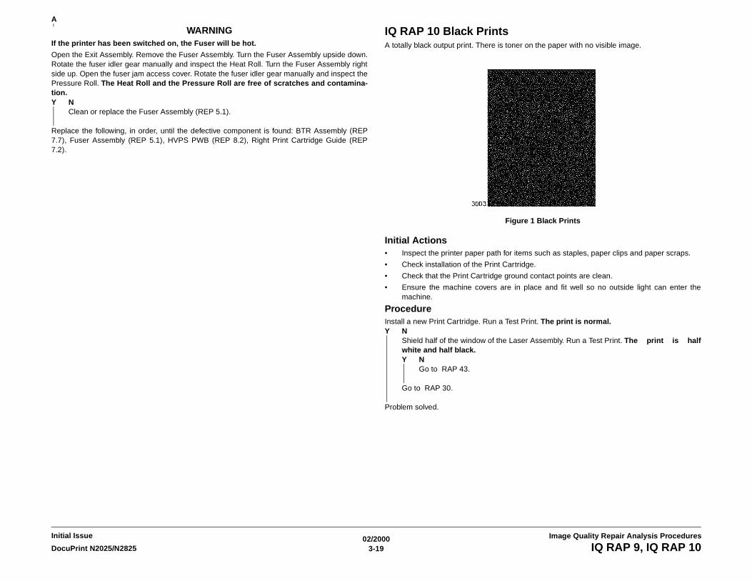
WARNING IQ RAP 10 Black Printsn the paper with no visible image.
1 Black Prints
s such as staples, paper clips and paper scraps.
e.
contact points are clean.
ace and fit well so no outside light can enter the
int. The print is normal.
Assembly. Run a Test Print. The print is half
A
02/20003-19DocuPrint N2025/N2825
Initial Issue
If the printer has been switched on, the Fuser will be hot.
Open the Exit Assembly. Remove the Fuser Assembly. Turn the Fuser Assembly upside down.Rotate the fuser idler gear manually and inspect the Heat Roll. Turn the Fuser Assembly rightside up. Open the fuser jam access cover. Rotate the fuser idler gear manually and inspect thePressure Roll. The Heat Roll and the Pressure Roll are free of scratches and contamina-tion.Y N
Clean or replace the Fuser Assembly (REP 5.1).
Replace the following, in order, until the defective component is found: BTR Assembly (REP7.7), Fuser Assembly (REP 5.1), HVPS PWB (REP 8.2), Right Print Cartridge Guide (REP7.2).
A totally black output print. There is toner o
Figure
Initial Actions• Inspect the printer paper path for item
• Check installation of the Print Cartridg
• Check that the Print Cartridge ground
• Ensure the machine covers are in plmachine.
ProcedureInstall a new Print Cartridge. Run a Test PrY N
Shield half of the window of the Laser white and half black.Y N
Go to RAP 43.
Go to RAP 30.
Problem solved.

DocuPrint N2025/N2825
Initial Issue
ntil the defective component is found: HVPS PWB 5.1), Paper Transport Assembly (REP 4.1), Laser
Cartridge Guide (REP 7.2), Print Engine Controller
A
02/20003-20IQ RAP 11
Image Quality Repair Analysis Procedures
IQ RAP 11 BackgroundThere is toner contamination on all or part of the page. The contamination appears as a verylight gray dusting (Figure 1).
Figure 1 Background
Initial Actions• Inspect the printer paper path for items such as staples, paper clips and paper scraps.
• Check installation of the Print Cartridge.
• Check that the Print Cartridge ground contact points are clean.
• Ensure the machine covers are in place and fit well so no outside light can enter themachine.
ProcedureInstall a new Print Cartridge (PL 8.1). Run a Test Print. The background is gone.Y N
Generate a Test Print and switch OFF the printer power halfway through the print cycle.Carefully remove the Print Cartridge and inspect the toner image on the drum just beforethe transfer area (BTR). The undeveloped areas of the drum are clean and withoutbackground.Y N
Go to RAP 43.
Remove the Print Cartridge. Check for the continuity, from the front opening, betweenmetal parts of the Paper Transport Assembly and the Printer Frame. The Paper Trans-port Assembly Baffle is grounded.Y N
Remove and clean the contact areas of the Paper Transport Assembly (REP 4.1).Reinstall the assembly so that it is grounded properly. If the problem persists,replace the Paper Transport Assembly (REP 4.1).
Clean or replace the Fuser Assembly (REP 5.1). The background is gone.
Y NReplace the following, in order, u(REP 8.2), Fuser Assembly (REPAssembly (REP 7.1), Right Print PWB (REP 8.5).
Problem solved.
Problem solved.
A

IQ RAP 12Image Quality Repair Analysis Procedures
IQ RAP 12 Uneven Density Panic stop the printer half way through the print cycle. Look at the image on the drum. Theimage on the drum has even density.
).
ser. The print on the paper has even density.
A
02/20003-21DocuPrint N2025/N2825
Initial Issue
Image density varies within the page in either direction (Figure 1).
Figure 1 Uneven Density
Initial Actions• Load fresh dry paper.
• Check that the correct Print Cartridge is properly installed and not empty.
• Ensure that the machine is reasonably level.
• Check to make sure the Laser path is clean and unobstructed.
• Remove the Print Cartridge and check the Left and Right Guides for ware, contamination,obstructions, etc.
• Clean the Laser window.
ProcedureRun a Test Print. The Test Print output image contains uneven print.Y N
Go to 1.5 Final Actions.
Install a new Print Cartridge (PL 8.1). Run a Test Print. The Test Print output image con-tains uneven print.Y N
Problem solved. Go to 1.5 Final Actions.
Check the Bias Transfer Roll (BTR) for contamination, even spring pressure, and proper instal-lation. The BTR is in good condition (not contaminated) and properly installed.Y N
Repair or replace the BTR Assembly (REP 7.7).
Check the Fuser Assembly for worn parts and for contamination on the Fuser Roll or PressureRoll. The Fuser Assembly is in good condition.Y N
Replace the Fuser Assembly (REP 5.1).
Y NReplace the Laser Assembly (REP 7.1
Look at the print on the paper before the FuY N
Replace the BTR (REP 7.7).
Replace the Fuser Assembly (REP 5.1).
A

DocuPrint N2025/N2825
Initial Issue
ray 2 Lower Turn Rolls. Check for obstructions orn. Clean or replace as necessary.
ay 2 Rear Chute. Check all rolls for obstructions orn. Clean or replace as necessary.
Feed Rolls. Clean or replace if necessary.
Retard Pad/Retard Roll. Clean or replace if neces-
eeder, check the Nudger Roll. Clean or replace if
ute between Tray 2 and Tray 1. Check for obstruc-tion. Clean as necessary.
ower Turn Rolls. Check for obstructions or contam-eplace as necessary.
Rear Chute. Check all rolls for obstructions or con- or replace as necessary.
Rolls. Clean or replace if necessary.
lope Feed Rolls. Clean or replace if necessary.
d Pad. Clean or replace if necessary.
n Rolls. Check for obstructions or contamination.cessary.
etween Tray 1 and the Registration Rolls. Check forination. Clean as necessary.
Clean or replace if necessary.
. Clean or replace if necessary.
eck for obstructions or contamination. Clean or
sor. Check actuation and for obstructions or con- as necessary.
heck actuation and for obstructions or contamina-ry.
an or replace if necessary.
. Clean or replace if necessary.
ce if necessary.
embly. Check for obstructions or contamination.
worn parts or rolls. Check for obstructions or con-sary.
ssembly. Check for obstructions or contamination.
r worn parts or rolls. Check for obstructions or con-sary.
A B C D E
02/20003-22IQ RAP 13
Image Quality Repair Analysis Procedures
IQ RAP 13 Skewed ImageThe image is not parallel to the edges of the print sheet (Figure 1).
Figure 1 Skewed Image
Initial Actions• Check the paper tray(s) installation and the paper in the tray(s).
• Load fresh dry paper.
• Paper meets specification.
• Check the paper path for any obstructions or debris that might hamper the passage of thepaper.
• Ensure the Print Cartridge is properly installed.
ProcedureRun 5 test prints, single sided, from each paper tray. If the printer has a Duplex Assembly, runfive duplexed prints from each tray. The skewed image appears only on duplexed prints.Y N
The skewed image occurs on prints fed from all trays.Y N
The skewed image occurs on prints fed from the MBF Tray.Y N
The skewed image occurs on prints fed from Tray 1.Y N
The skewed image occurs on prints fed from Tray 2.Y N
• Check the Tray 3 Feed Rolls. Clean or replace if necessary.
• Check the Tray 3 Retard Pad/Retard Roll. Clean or replace ifnecessary.
• If a 2000 Sheet Feeder, check the Nudger Roll. Clean or replaceif necessary.
• Check the feed chute between Tray 3 and Tray 2. Check forobstructions or contamination. Clean as necessary.
• Check the Tcontaminatio
• Check the Trcontaminatio
• Check the Tray 2
• Check the Tray 2 sary.
• If a 2000 Sheet Fnecessary.
• Check the feed chtions or contamina
• Check the Tray 1 Lination. Clean or r
• Check the Tray 1 tamination. Clean
• Check the Tray 1 Feed
• Check the Tray 1 Enve
• Check the Tray 1 Retar
• Check the Tray 1 TurClean or replace as ne
• Check the feed chute bobstructions or contam
• Check the MBF Feed Rolls.
• Check the MBF Retard Pad
• Check the MBF Chute. Chreplace as necessary.
• Check the Registration Sentamination. Clean or replace
• Check the Registration Sensor. Ction. Clean or replace as necessa
• Check the Registration Rolls. Cle
• Check the BTR Roll and bearings
• Check the Print Cartridge. Repla
• Check the Paper Transport AssClean or replace as necessary.
• Check the Fuser Assembly. Check fortamination. Clean or replace as neces
• Check all rolls and drives in the Exit AClean or replace as necessary.
• Check the Duplex assembly. Check fotamination. Clean or replace as neces
A B C D E

IQ RAP 13, IQ RAP 14Image Quality Repair Analysis Procedures
• Check the rear chute between the Duplex Assembly and the Registration Rolls. Check forworn parts or rolls. Check for obstructions or contamination. Clean or replace as neces-
IQ RAP 14 Damaged Printither wrinkled, creased, or torn (Figure 1).
Damaged Print
fresh.
nts in the paper path are clean and unobstructed.
n.
The paper fed crooked.
d paper. Run a Test Print. The paper is still dam-
Fuser Assembly. Turn the Fuser Assembly upsidenually and inspect the Heat Roll. Turn the Fuser
r jam access cover. Rotate the fuser idler gear man-e Heat Roll and the Pressure Roll are free of
bly (REP 5.1).
feed tray and the exit tray for contamination or obstructions.
ation from the paper path.
r path, between the feed tray and the exit tray, foraper path rolls are free of contamination, wear,
02/20003-23DocuPrint N2025/N2825
Initial Issue
sary. The printed page comes out of the printer e
Figure 1
Initial Actions• Check that the paper supply is dry and
• Check that rollers and other compone
• Ensure that paper is within specificatio
ProcedureObserve paper feed as you run a test print.Y N
Replace paper with fresh, dry standaraged.Y N
Problem solved.
Open the Exit Assembly. Remove thedown. Rotate the fuser idler gear maAssembly right side up. Open the fuseually and inspect the Pressure Roll. Thscratches and contamination.Y N
Clean or replace the Fuser Assem
Inspect the paper path between theobstructions. The paper path is free ofY N
Remove obstructions or contamin
Inspect all of the rolls along the papecontamination, wear or damage. The por damage.
A

DocuPrint N2025/N2825
Initial Issue
paper. It may be off in either the process direction
1 Registration
in specification.
fresh and loaded correctly.
set correctly.
nts in the paper path are clean and unobstructed.
e is properly registered.
1). The printer registration is set correctly.
e (ADJ 1.1).
direction, replace in sequence as necessary: Reg-Registration Clutch (REP 4.3), Main Gear Driveor Assembly (REP 6.2), Registration Sensor (REPP 8.5), or System Controller PWB (REP 8.1).ocess direction, replace in sequence as necessary:B (REP 8.1).
he print image is properly registered.
Customer Support.
A
02/20003-24IQ RAP 14, IQ RAP 15
Image Quality Repair Analysis Procedures
Y NReplace the damaged or worn roll (REP 3.1).
Install a new Print Cartridge. Run a Test Print. The print is still damaged.Y N
Problem Solved.
Replace the following, in order, until the defective component is found: Fuser Assembly(REP 5.1), Paper Transport Assembly (REP 4.1), BTR Assembly (REP 7.7), MBF FeedRoll Assembly (REP 2.2), Retard Holder Assembly (REP 2.5), Rear Chute Assembly(REP 3.2), Turn Roll Assembly (REP 2.4), Feed Roll (REP 2.2/ REP 2.10), Tray Assembly(PL 2.1/ PL 2.2).
Go to IQ RAP 13.
IQ RAP 15 RegistrationThe image is not positioned correctly on theor in the scan direction (Figure 1).
Figure
Initial Actions• Check to ensure that the paper is with
• Check that the paper supply is dry and
• Check that the Paper Tray guides are
• Check that rollers and other compone
ProcedureRun a test print. The Test Print output imagY N
Perform the registration check (ADJ 1.Y N
Perform the registration procedur
If misregistration occurs in the processistration Rolls (REP 4.4/ REP 4.5), Assembly (REP 6.1), Main Drive Mot4.6), Print Engine Controller PWB (REIf misregistration occurs across the prLaser (PL 8.1), System Controller PW
Have the customer send another print job. TY N
Have the customer contact the Xerox
Problem Solved.

IQ RAP 16, IQ RAP 17Image Quality Repair Analysis Procedures
IQ RAP 16 Skips / Smears IQ RAP 17 Unfused Imageaper. The image rubs off easily (Figure 1).
Unfused Image
in specification.
m an unopened ream. Run a test print. The prob-
nd check the Fuser setting. The NV code is set to
e. Run 25 test prints. The problem is still
increment.
ion.
r Assembly. Turn the Fuser Assembly upside down.spect the Heat Roll. Turn the Fuser Assembly rightotate the fuser idler gear manually and inspect theure Roll are free of scratches and contamina-
02/20003-25DocuPrint N2025/N2825
Initial Issue
A disturbance of the image which lengthens or shortens the image in the process direction. Adarkening across the process direction or a repeat of the image in the process direction (Figure1).
Figure 1 Skips / Smears
Initial Actions• Check that the paper supply is dry and fresh.
• Check to ensure that the paper is within specification.
• Check the paper path for any obstructions or debris.
ProcedureRun a test print. The image has skips or smears.Y N
Problem Solved.
Check, clean, or replace as necessary in the following sequence:• The Paper Transport gears, pulleys, or other components (REP 4.1).
• The Main Drive components (REP 6.1).
• The Fuser drive components (REP 5.4/ REP 5.5).
• The Fuser Assembly (REP 5.1).
The defect still occurs.Y N
Problem Solved.
Replace the Print Cartridge (PL 8.1).
The printed image is not fully fused to the p
Figure 1
Initial Actions• Check to ensure that the paper is with
ProcedureReplace the paper with fresh, dry paper frolem is still present.Y N
Problem solved.
Refer to Nonvolatile Memory Setup Mode athe factory default value.Y N
Set NV code to the factory default valupresent.Y N
Problem Solved.
Increase the fuser temperature by one
The overall print density is within specificatY N
Go to IQ RAP 1
Open the Exit Assembly. Remove the FuseRotate the fuser idler gear manually and inside up. Open the fuser jam access cover. RPressure Roll. The Heat Roll and the Presstion.

DocuPrint N2025/N2825
Initial Issue
nnot be reproduced clearly on the print.
he default value.
he image quality test print. The Test Print output
he defective component is found: Laser Assemblyr Supply (REP 8.2).
02/20003-26IQ RAP 17, IQ RAP 18
Image Quality Repair Analysis Procedures
Y NClean or replace the Fuser Assembly (REP 5.1).
Open the fuser jam access cover. Rotate the fuser idler gear manually and inspect the contactbetween the Heat Roll and the Pressure Roll along the rotation. The Heat Roll and the Pres-sure Roll are contacting each other uniformly.Y N
Replace the Fuser Assembly (REP 5.1).
Replace the following, in order, until the defective component is found: Fuser Assembly (REP5.1), Print Engine Controller PWB (REP 8.5), Low Voltage Power Supply (REP 8.6).
IQ RAP 18 ResolutionThe two pixel lines and halftone patches ca
Initial Actions• Ensure that the print density is set to t
ProcedureInstall a new Print Cartridge (PL 8.1). Run tresolution is good.Y N
Replace the following, in order, until t(REP 7.1) then the High Voltage Powe
Problem Solved.