3-i case review & image critique - opeart.comopeart.com/case-review-image-critique.pdfcase...
TRANSCRIPT

8/24/2014
1
Case Review & Image Case Review & Image CritiqueCritiqueCritiqueCritique
Olive Peart, M.S. R.T. (R)(M)www.opeart.com
West Physics Consulting is a proud supporter of MTMI’s Diagnostic Imaging Programs.
Thank you West Physics!
The Need for Dedicated The Need for Dedicated Mammography ImagingMammography Imaging
Breast is all soft tissue Similar mass densities Need to maximize d o a
contrast Need highest possible
resolution Need to keep radiation
doses low
Digital Mammography TubeDigital Mammography Tube
Electronic vacuum tube Two electrode
T t T t t A d ◦ Tungsten Target at Anode Single tracks more reliable and less expensiveMaximum anode heat loading of dual tracks are inferior to single tracks Single track tungsten tubes support 2-3 times the max anode load vs. dual track
◦ Cathode with filament
Inherent & Added Filtration Inherent & Added Filtration ◦Inherent:OilGlass or metal window of x-ray t btubeMirror assemblyCompression plate ◦Added:Rh/Ag/AlMo (analog)
Line Focus PrincipleLine Focus Principle
The line focus principle allows a large area of focal spot heating while keeping heating while keeping the effective focal spot small
Decreasing target angle = decreasing effective focal spot size

8/24/2014
2
Anode Heel EffectAnode Heel Effect SID 60-70 cm FOV 24 x 30cm
Reduce variation of du a a o ointensity due to heel effect
Cathode-anode orientation◦ Anode at nipple
HalfHalf--Field GeometryField Geometry Central axis of beam
parallel to chest wall 24x30cm FOV
requires mim. effective anode angle effective anode angle of 20-24˚(tube tilt + anode angle)◦ Typical 16˚anode angle
+ 6˚ tube tilt
Grids Grids
Improve contrast Decrease scattered
radiation Results in more radiation Results in more radiation
dose to patient◦ Always used in routine imaging◦Never used in magnification mammography or Tomo
Characteristic of the GridCharacteristic of the Grid Focused grid Grid ratio 3:1 to 5:1
– focused to the SID Grid frequency 30-50 q y
lines per cm Grid interspace
material◦ Carbon◦ Wood
High Transmission Cellular (HTC) GridHigh Transmission Cellular (HTC) Grid
Characteristics of a crossed-grid
Reduces scatter in two directions rather than one
Copper as the lead strip Air as the interspace
material Result in less radiation
to patient
Focal Spot Size Focal Spot Size
0.4 mm or smaller for routine work. The most commonly used is 0.3mm.
0.15 mm or smaller for magnification. The most common focal spot size in magnification is 0.1mm.

8/24/2014
3
Back Back Up Up TimersTimers
Needed to avoid gross overexposure Maximum back up time =◦ 600 mAs for grid techniques◦ 300 for non-grid workA id b k ti b i Avoid back-up timer by using higher kVp not higher mAs
The back up time will reach if an implant covers the majority of the detector
Automatic Exposure Control Automatic Exposure Control
Analog: The ionization chamber ◦ The AEC device is positioned below the IR to minimize OID
Digital: Amorphous selenium or Scintillation phosphors (e.g. Cesium iodide)◦ Entire image detector serves as the AEC devices
Exposure ModesExposure Modes
Manual – operator selects all parameters Auto-time – system selects mAs, operator
selects filter and kVA t kV t l t kV d A Auto-kV – system selects kV and mAs, operator selects filter
Auto-filter – system selects filter, kV and mAs
Input Input -- Patient InformationPatient Information Work list◦ Patient’s name selected from a list
IP scanner◦ Used with CMUsed with CM
Magnetic card swipe◦ Patient’s information on credit card-like device
Digital ImagingDigital Imaging
Latent image –formed on digital detector
ADC – sends signal from detector to computer
LCD (Display monitor)
Biggest AdvantageBiggest Advantage
Wide latitude Linear response
to the intensity of x ray of x-ray exposure
Optimization of contrast

8/24/2014
4
Exposure LatitudeExposure Latitude Range of exposures (under/over) that
can be used ◦ Analog receptors can produce an acceptable image within a range of 30% underexposure and 50% overexposureDi it l i i d t bl ◦ Digital imaging can produce an acceptable image at 50% underexposure and 100% overexposure
Digital can correct exposure factors over 100% times greater than or 50% less than normal range
Pre ProcessingPre Processing
Automatic Rescaling will correct Raw Data◦ Enhance contrast &
sharpness ◦ Corrects artifacts due to ◦ Corrects artifacts due to
bad detector elements◦ Applies processing
algorithms Generates a histogram
Other Advantages of DigitalOther Advantages of Digital Improve workflow by
reducing repeats Reduce cost
associated with associated with repeats
Reduction in lost films Every reprint is an
original◦ Medico legal risk reduced
Disadvantages of DigitalDisadvantages of Digital
Start-up cost Visual cues of over and under exposure
not easily seen◦Decrease contrast (over exposure)◦Decrease contrast (over exposure)◦Quantum noise (under exposure)
Loss of experience with manipulating technical factors and film processing
Loss of ability to control patient dose De-emphasize thinking of radiation
safety and patient protection
Other FearsOther Fears
Outsourcing of reports – eliminating the need for a radiologist at any one site
An insufficient backup system
The Digital ImageThe Digital Image
Digital is formed as a 2-dimensional (2-D) matrix of picture elements (pixels)
The matrix A box of cells ◦ The matrix–A box of cells with numeric values arranged in rows and columns
Each cell corresponds to a specific location in the image
8/24/2014
5
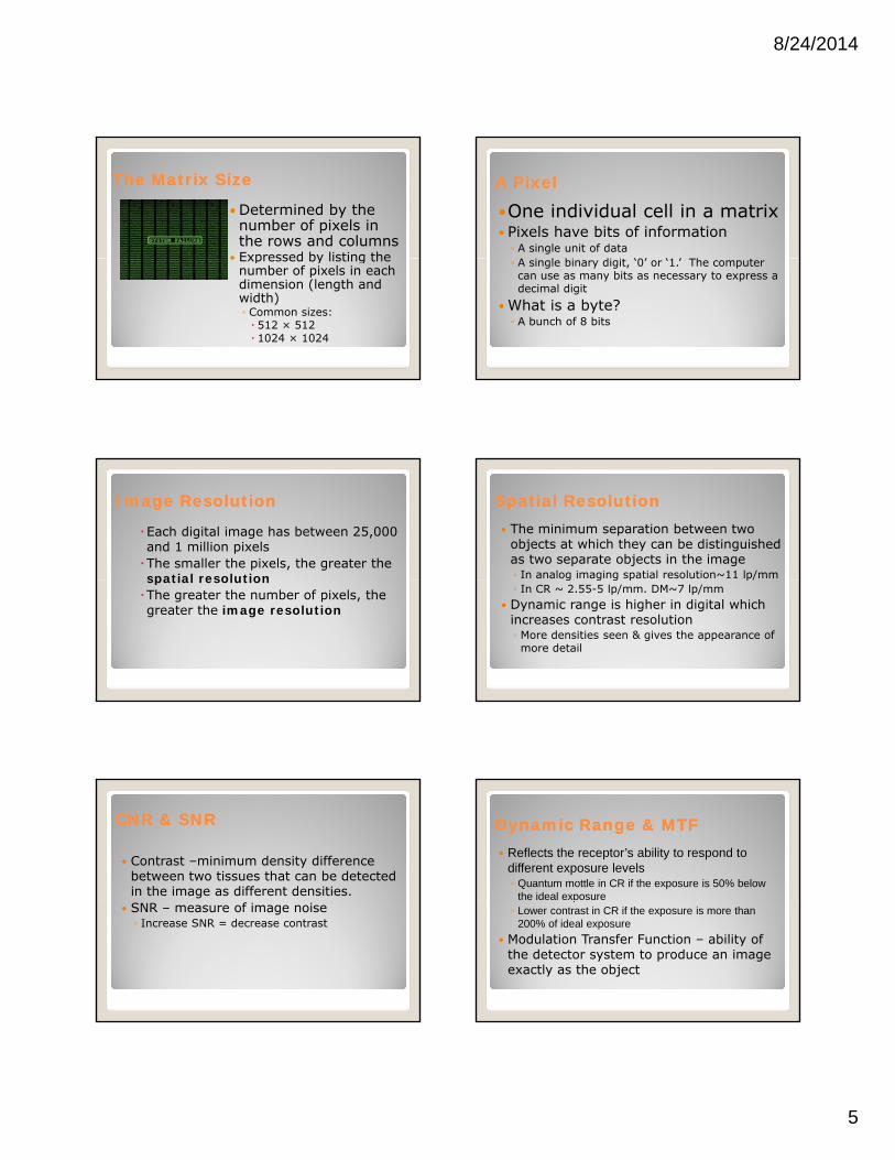
The Matrix SizeThe Matrix Size
Determined by the number of pixels in the rows and columns
Expressed by listing the Expressed by listing the number of pixels in each dimension (length and width)◦ Common sizes: 512 × 512 1024 × 1024
A PixelA Pixel
One individual cell in a matrix Pixels have bits of information◦ A single unit of data
i l bi di i ‘0’ ‘ ’ h◦ A single binary digit, ‘0’ or ‘1.’ The computer can use as many bits as necessary to express a decimal digit
What is a byte?◦ A bunch of 8 bits
Image ResolutionImage Resolution
Each digital image has between 25,000 and 1 million pixelsThe smaller the pixels, the greater the spatial resolutionspatial resolutionThe greater the number of pixels, the greater the image resolution
Spatial ResolutionSpatial Resolution The minimum separation between two
objects at which they can be distinguished as two separate objects in the image◦ In analog imaging spatial resolution~11 lp/mmg g g p p/◦ In CR ~ 2.55-5 lp/mm. DM~7 lp/mm
Dynamic range is higher in digital which increases contrast resolution ◦ More densities seen & gives the appearance of more detail
CNR & SNRCNR & SNR
Contrast –minimum density difference between two tissues that can be detected in the image as different densities.
SNR – measure of image noise◦ Increase SNR = decrease contrast
Dynamic Range & MTFDynamic Range & MTF Reflects the receptor’s ability to respond to
different exposure levels◦ Quantum mottle in CR if the exposure is 50% below
the ideal exposure p◦ Lower contrast in CR if the exposure is more than
200% of ideal exposure
Modulation Transfer Function – ability of the detector system to produce an image exactly as the object

8/24/2014
6
Window Level & WidthWindow Level & Width Window level controls
the brightness displayed ◦ Increase window level =
increase brightness Window width controls Window width controls
the ratio of black to white displayed therefore the contrast ◦ Increase window width =
decrease contrast
Brightness & ContrastBrightness & Contrast Image Brightness – controlled by the
processing software (not mAs) ◦ Brightness can be altered after the exposure.
Image contrast – controlled by processing f ( k )software (not kVp)
◦ Contrast can be altered after the exposure. Recorded Detail – controlled by the digital
acquisition i.e. pixel size and display matrix and the capabilities of the monitor
LCD MonitorsLCD Monitors Has DAC - Converts the
electronic signal from the computer to light (a visible image)M it l ti d d Monitor resolution depends on the pixel pitch ◦ the pixel pitch is the distance between cells of the same color
Post Processing Post Processing AWS allows rapid viewing of the image◦ Low resolution◦ Post processing of image
RWS for interpretation◦High resolution
Change Brightness/ContrastChange Brightness/Contrast Images Images -- Dense and Fatty BreastDense and Fatty Breast

8/24/2014
7
Imaging Calcifications or Spot Imaging Calcifications or Spot CompressionCompression
Inverting Image or Add Ruler or Inverting Image or Add Ruler or TextText
Image ZoomImage Zoom Other Post ProcessesOther Post Processes Noise reduction or suppression -
removes signals that do not provide useful image data
Edge enhancement , frequency processing or spatial frequency processing or spatial frequency filtering
Smoothing Background removal or shuttering
Storage OptionsStorage Options
Electronic image storage or archival in encoded form to reduce space◦ Short term – local storage gon the hard drive◦ Medium term – redundant array of independent disks
(RAID)◦ Long term – digital linear tapes, RAID or optical disk◦ Compressed storage
Image CompressionImage Compression
Required for teleradiography◦Lossy◦Lossless
Lossy is acceptable in general radiography but not acceptable for mammography

8/24/2014
8
Laser PrintingLaser Printing
Processing without chemicals
No drainage or water connection
Film can be handled under daylight conditions – no darkroom needed
Disadvantage Very expensive Optical density and latitudes lower
PACS & Teleradiography PACS & Teleradiography PACS – Picture Achieving and Communication
System◦ DICOM compatibility◦ Modality comparison
P i fil i◦ Prior film comparison Teleradiography – images can be transmitted
to distant locations e.g. Radiologist’s home◦ Virtual consultation◦ Internet access to images – via telephone, cable or
satellite
Understanding Digital QCUnderstanding Digital QC MQSAMQSA Mammography Quality Standards Act –
enacted October 27, 1992 Enforcement by FDA began in 1995 ◦ All mammography units must be: Accredited Certified Inspected
Certifying AgenciesCertifying Agencies
FDA or FDA approved certifying state The FDA will not certify facilities in
approved certifying states and certifying states can only certify certifying states can only certify facilities within their state borders
The FDA - approved certifying states are: Illinois, Iowa, South Carolina and Texas
Accreditation BodiesAccreditation Bodiesin USin US
American College of Radiology (ACR), States of Arkansas, Iowa and Texas
State accreditation bodies can accredit only those facilities that are located in their respective states
State accreditation bodies or FDA can only accredit specific FFDM models

8/24/2014
9
Quality Standard IncludeQuality Standard Include Regular quality control testing Mandatory initial qualifications for
mammographer, radiologist and physicistp y
Enforcing continuing education qualification for mammographer, radiologist and physicist
Regular inspection of mammography facilities
Key Components of the MQSA Key Components of the MQSA Certificate placement Consumer complaints mechanism Infection control Self referrals
Medical records Medical records Record keeping & transferring of
records (HIPAA) Communication of results to patient Assessment categories Medical audit Personnel requirements
Qualification & Qualification & DocumentationsDocumentations
There are 3 different initial requirements: Prior to 10/1/94 Between 10/1/94 & 4/28/99
After 4/28/99 After 4/28/99
Initial QualificationInitial Qualification--MammographerMammographer
After 4/28/99 Complete 27.5 hours mammography
course Complete 25 supervised exams (12.5hrs)◦ State specific i.e. State license
Board Certification (ARRT or ARCRT) 8-hours edu specific to digital 8- hours edu specific to DBT
BBenefits enefits of CQIof CQI
Reduction of unnecessary radiation to patient by reducing repeat
Improve overall efficiency of service
Improved patient satisfaction
Consistency of image production
Cost effectiveness
Analog Quality Control Analog Quality Control Mammograher Testing Duties
Daily tasksDarkroom cleanliness/ processor quality control
Weekly tasksViewbox and viewing conditions/phantom iimages
Monthly tasksVisual checklist
Quarterly tasksRepeat analysis/ analysis of fixer retention
Semiannual taskDarkroom fog testing/ screen-film contact/compression
8/24/2014
10
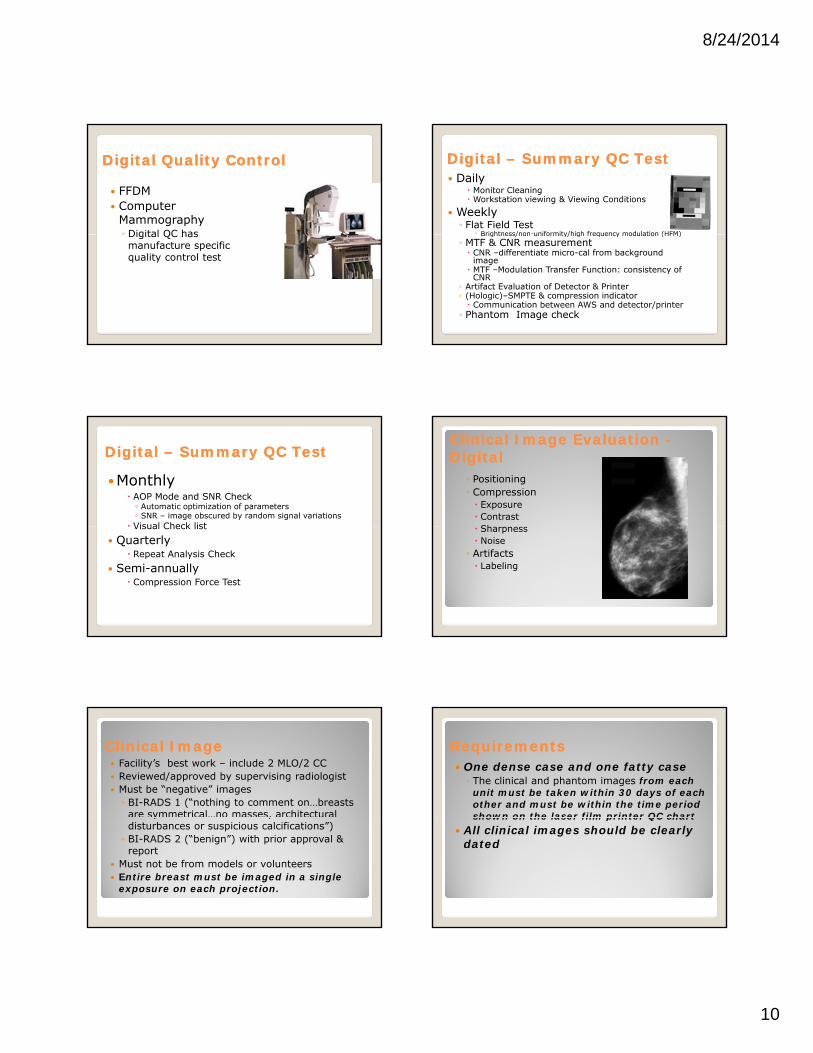
Digital Quality ControlDigital Quality Control
FFDM Computer
Mammography◦ Digital QC has ◦ Digital QC has manufacture specific quality control test
Digital Digital –– Summary QC TestSummary QC Test Daily
Monitor Cleaning Workstation viewing & Viewing Conditions
Weekly◦ Flat Field Test
◦ Brightness/non-uniformity/high frequency modulation (HFM)Brightness/non uniformity/high frequency modulation (HFM)◦ MTF & CNR measurement CNR –differentiate micro-cal from background
image MTF –Modulation Transfer Function: consistency of
CNR◦ Artifact Evaluation of Detector & Printer◦ (Hologic)–SMPTE & compression indicator Communication between AWS and detector/printer
◦ Phantom Image check
Digital Digital –– Summary QC TestSummary QC Test
Monthly AOP Mode and SNR Check◦ Automatic optimization of parameters◦ SNR – image obscured by random signal variations
Visual Check list Visual Check list Quarterly
Repeat Analysis Check Semi-annually
Compression Force Test
Clinical Image Evaluation Clinical Image Evaluation --DigitalDigital
◦ Positioning◦ Compression Exposure ContrastSh Sharpness Noise
◦ Artifacts Labeling
Clinical ImageClinical Image Facility’s best work – include 2 MLO/2 CC Reviewed/approved by supervising radiologist Must be “negative” images◦ BI-RADS 1 (“nothing to comment on…breasts are symmetrical…no masses, architectural y ,disturbances or suspicious calcifications”)◦ BI-RADS 2 (“benign”) with prior approval & report
Must not be from models or volunteers Entire breast must be imaged in a single
exposure on each projection.
RequirementsRequirements One dense case and one fatty case ◦ The clinical and phantom images from each unit must be taken within 30 days of each other and must be within the time period shown on the laser film printer QC chart shown on the laser film printer QC chart
All clinical images should be clearly dated
8/24/2014
11
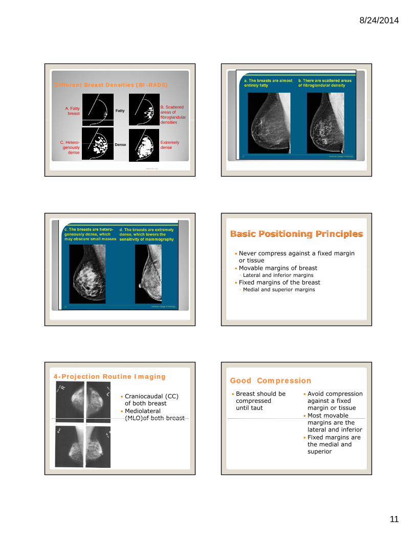
Different Breast Densities (BIDifferent Breast Densities (BI--RADS)RADS)
FattyA. Fatty
breast
B. Scattered areas of fibroglandular
www.acr.org
densities
C. Hetero-genously
dense
Extremely dense
Dense
Never compress against a fixed margin or tissue
Movable margins of breastMovable margins of breast◦ Lateral and inferior margins
Fixed margins of the breast◦ Medial and superior margins
44--Projection Projection Routine ImagingRoutine Imaging
Craniocaudal (CC) of both breast
Mediolateral (MLO)of both breast(MLO)of both breast
Good CompressionGood Compression Breast should be
compressed until taut
Avoid compression against a fixed margin or tissue
Most movable margins are the lateral and inferior
Fixed margins are the medial and superior

8/24/2014
12
Key Point for the CCKey Point for the CC IP at elevated inframammary crease Ipsilateral arm down. Contralateral arm
raised - holding the machine for support Must include, within 1 cm, the same , ,
amount of tissue measured on the MLO Best demonstrates the anterior, central,
medial and posteromedial portions of breast – poorly visualize lateral breast tissue
Image Evaluation Image Evaluation --CCCC
Nipple in profile/centered Medial and lateral tissue
in the collimated field◦ Nipple centered
Pectoral muscle not always seen
CC should include within 1cm the PNL measurement of the MLO
Dense area adequately penetrate
Key Points for the MLOKey Points for the MLO Tube angulation will vary between 30 –
70 degrees depending of patient size i.e. Image plate parallel to muscle.
Arm closest to the breast being imaged, draped over the top of image plate.draped over the top of image plate.
The image plate in the armpit. Compression must support the anterior
breast tissue to preventing sagging & distortion of ductal architecture.
The pectoral muscles should be demonstrated to the level of nipple.
MLO Imaging MLO Imaging
MLO best demonstrates the extreme posterior and upper outer quadrant
Distortion of the anterior Distortion of the anterior, central and medial breast tissue
MLO positioningMLO positioning The more parallel
the image plate is to the pectoralis muscle the more tissue will be included in the image.
Source: ACR Manual 1999
Image Evaluation Image Evaluation -- MLOMLO
Pectoral muscle extend to or below the PNL
Inframammary fold open
Dense areas well penetrated

8/24/2014
13
Problem Imaging the MLOProblem Imaging the MLO
Drooping breast Abdominal tissue
superimposing the inframammary foldinframammary fold
Missing posterior breast
Imaging ImplantsImaging Implants
Routine 4-projection MLO and CC with limited compression
4 ID-projection series –MLO & CCM bilit i & f t Mobility, compression & exposure factors
depend on: Type of implantDegree of scarring and adhesion of theimplant to the chest wallBreast size and amount of actual tissue
EightEight--projection Seriesprojection Series
Standard projections demonstrates margins of the implantimplant◦ Manual technique may be necessary
EightEight--projection Seriesprojection Series
Modified (ID) projections demonstrate breast tissue◦Manual or AEC ◦Manual or AEC techniques depending on amount of breast tissue over the detector
ID TechniqueID Technique
Locate the extent of the implant
Have the patient step away from the unit
Place the IP just posterior to edge of posterior to edge of implant
Use thumb and finger to hold anterior breast
Compress. The edge of IP helps keep the implant back
Standard projection are inadequate Suspicious area seen on one projection
only Suspicious area needs work-up to avoid p p
the trauma of surgery

8/24/2014
14
90-degree mediolateral -ML
Lateromedial -LM L t di l
From Below - FB Cleavage - CV Axillary Tail – AT Superior-Inferior
Lateromedial oblique -LMO
Tangential - TAN Exaggerated craniocaudal –XCCL or XCCM
Supe o e oOblique - SIO
Positions◦ Rolled positions:◦ RM, RL & RS, RI◦ Magnification and
spot Ingenious!Ingenious!
In the normal anatomy the patient’s nipple does not fall in profile. What are your options?What are your options?
A. Image the entire breast first – using nipple marker. Separate imaging with nipple in profile - only if necessary
B. It is the normal anatomy. No added imaging necessary A
You are imaging an elderly patient with very thin breast. How do you eliminate the wrinkling?
A. Repeat. Push breast tissue posteriorly to remove wrinkling. Send repeat image
B. Leave wrinkling, do not repeat
C. Repeat. Push breast tissue posteriorly to remove wrinkling. Send both images
D. Use the XCCL projection C
How do you eliminate this skin fold in the axilla?
A. Smooth back the breast tissuetissue
B. Raise patient’s arm higher C. Lower patient’s armD. Additional imaging or
supplementary projections may be necessary
D
On this RCC the fold should be removed. What is its likely location?
A.On the mediolateral aspect of the breast
B.On the superior aspect of the breast
C.On the inferior aspect of the breast
D.On the lateral breast
C
8/24/2014
15
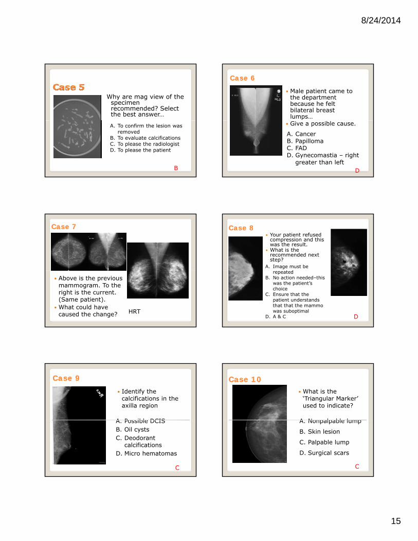
Why are mag view of the specimen recommended? Select the best answer…
A. To confirm the lesion was removed
B. To evaluate calcificationsC. To please the radiologistD. To please the patient
B
Case Case 66
Male patient came to the department because he felt bilateral breast lumps…
Give a possible cause.
A. CancerB. PapillomaC. FADD. Gynecomastia – right
greater than left D
Case Case 77
Above is the previous mammogram. To the right is the current. (Same patient).
What could have caused the change? HRT
Case Case 88 Your patient refused
compression and this was the result.
What is the recommended next step?
A. Image must be drepeated
B. No action needed–this was the patient’s choice
C. Ensure that the patient understands that that the mammo was suboptimal
D. A & C D
Case Case 99 Identify the
calcifications in the axilla region
A Possible DCISA. Possible DCISB. Oil cystsC. Deodorant
calcificationsD. Micro hematomas
C
Case Case 1010 What is the
‘Triangular Marker’ used to indicate?
A Nonpalpable lumpA. Nonpalpable lump
B. Skin lesion
C. Palpable lump
D. Surgical scars
C

8/24/2014
16
You noticed a lesion in the posterior aspect of the right breast.
What do you think What do you think the radiologist will suggest as the next image?
A. Repeat MLOB. Spot compression /mag C. XCCLD. Magnification onlyB
Case Case 12 12 What problem is
demonstrated here?
Nipple not Nipple not centered & not in profile
Clipping of medial breast
Case Case 1313
What problems are demonstrated here?
Closed IFClosed IF
Nipple not in profile
Not enough pec muscle
Case Case 1414 Identify the problem
•Medial Breast overlap
Case Case 15 15
What is obscuring the axillary breast tissue?
What other problem?
ArmNo open IF seenDrooping anteriorSkin fold in axilla
Case Case 1616
What problem is demonstrated here?
Tissue overlap on pmedial breast

8/24/2014
17
Identify the projection
CleavageCleavage
Identify the projection
AT
Identify the projection
90 ML90 ML
Identify the projection & problem
ML – 90ML 90
Clip IF
Identify the projection
XCCL
This artifact appeared during a needle localization. Identify the artifact…
•Patient gown

8/24/2014
18
Case 23 Which area of
breast tissue is missing◦ A. medial◦ B. lateral◦C. anterior◦D. posterior
lateral
Case 24
Identify the pathology and problem
Dimpling
No open IF
Case 25
Identify a possible cause of the problem
Finger
Skin fold cause by past lumpectomy
Case 26 What is the main
reason for the closed IF here?
Fold of skin
Quiz ShowQuiz ShowQuiz ShowQuiz Show
The tail of Spence is easily The tail of Spence is easily visualized using the AT projectionvisualized using the AT projection

8/24/2014
19
What area of the breast is best What area of the breast is best imaged using the Cleavage?imaged using the Cleavage?
Which projection is often used to Which projection is often used to prove “teacup” benign calcificationprove “teacup” benign calcification
Note: The ML cannot be Note: The ML cannot be used to replace the MLO
When imaging the kyphotic patient, When imaging the kyphotic patient, instead of the CC we could use the… instead of the CC we could use the…
When using magnification, the skin When using magnification, the skin dose is much higher than routine dose is much higher than routine imaging.imaging.
Spot compression can be Spot compression can be performed in any projection.performed in any projection. The true reverse of the MLO is the The true reverse of the MLO is the

8/24/2014
20
The XCCL projection is used to image The XCCL projection is used to image the extreme lateral aspect of the breast the extreme lateral aspect of the breast with the patient positioned CC with the patient positioned CC
Which positions can be used to Which positions can be used to remove superimposed tissue remove superimposed tissue
Rolled Lateral (RL)Rolled Lateral (RL)Rolled Medial (RM)
Rolled Superior (RS)Rolled Inferior (RI)
In additional to the CC & MLO which In additional to the CC & MLO which projections is often utilized when projections is often utilized when imaging the lumpectomy patient.imaging the lumpectomy patient.
The LM can be used to improve The LM can be used to improve details of medial lesions.details of medial lesions.
When imaging the male breast, on which When imaging the male breast, on which projection would chest hair present a projection would chest hair present a problem?problem?
The TAN projection can be used The TAN projection can be used to locate skin calcifications.to locate skin calcifications.

8/24/2014
21
The SuperiorThe Superior--inferior Oblique (SIO) inferior Oblique (SIO) directs the beam from the…directs the beam from the…
Inferior lateral to the inferior medial aspect of the breast
Superior lateral to the superior medial aspect of the breast
None of the above
Lateral to the inferior medial aspect of the breast
Superior lateral to the inferior medial aspect of the breast
Match the following associations:Match the following associations:
Magnification
Lumpectomy imaging
Spatula
Depressed sternum
Pectus excavatum
Large breast
Small breast
Microcalcifications
Skin folds
Sectional Imaging
Questions???
Thank You!Thank You!