3-d forming of paper materials - simple search1061822/fulltext01.pdf · 3-d forming of paper...
TRANSCRIPT

3-D Forming of Paper Materials
ERIC LINVILL
Doctoral Thesis no. 99, 2017
KTH Royal Institute of Technology
School of Engineering Sciences
Department of Solid Mechanics
SE-100 44, Stockholm, Sweden


TRITA HFL-0608
ISSN 1654-1472
ISRN KTH/HFL/R-17/03-SE
ISBN 978-91-7729-250-0
© Eric Linvill, 2017
Akademisk avhandling som med tillstånd av KTH i Stockholm framlägges till offentlig
granskning för avläggande av doktorsexamen fredagen den 10 februari kl. 14:00 i sal F3,
KTH, Lindstedtsvägen 26, Stockholm. Avhandlingen försvaras på engelska.

Abstract
Paper materials have a long history of use as a packaging material,
although traditional paper-based packaging is limited in its shape,
complexity, and design. In order to better understand the deformation
and failure mechanisms during 3-D forming, two experimental studies of
paper materials have been conducted. Furthermore, constitutive
modeling combined with explicit finite element modeling have been
validated against numerous experimental setups and utilized to develop
further understanding of 3-D forming processes.
Two experimental studies were necessary to further investigate and
model the 3-D formability of paper materials. The combined effect of
moisture and temperature on the uniaxial mechanical properties of paper
was investigated, providing new insights into how moisture and
temperature affect both the elastic and plastic properties of paper
materials. Furthermore, the in-plane, biaxial yield and failure surfaces
were experimentally investigated in both stress and strain space, which
gave an operating window for 3-D forming processes as well as input
parameters for the constitutive models.
The constitutive modeling of paper materials and explicit finite
element modeling were directed towards two 3-D forming processes:
deep drawing and hydroforming. The constitutive models were calibrated
and validated against simple (typically uniaxial) mechanical tests, and the
explicit finite element models (which utilize the developed constitutive
models) were validated against 3-D forming experiments. Hand-made
papers with fibers partially oxidized to dialcohol cellulose, which has
greater extensibility than typical paper materials, was furthermore
characterized, modeled, and 3-D formed as a demonstration of the
potential of modified paper fiber products for 3-D forming applications.
Keywords
3-D forming, finite element method, constitutive model, moisture,
temperature, biaxial, hydroforming, deep drawing.
Sammanfattning
Papper har länge framgångsrikt använts som förpackningsmaterial,
men traditionella pappers- och kartongförpackningar är begränsade i
form och design. Två experimentella studier har utförts för att få bättre
förståelse för deformations- och brottmekanismer under 3D formning.
Resultat från konstitutivmodellering i kombination med explicit finit
element modellering har validerats mot ett flertal experimentella
uppställningar och använts för att utveckla bättre förståelse för 3D
formningsprocesser.
Två experimentella studier var nödvändiga för att ytterligare
undersöka och modellera pappersmaterials 3D formbarhet. I den första
undersöktes den kombinerade effekten av fukt och temperatur på
pappers enaxliga mekaniska egenskaper, vilket gav nya insikter om hur
fukt och temperatur påverkar både de elastiska och de plastiska
egenskaperna hos papper. I den andra har biaxiella (i planet) flyt- och
brottytor undersökts experimentellt i både spännings- samt
töjningsrymden, vilket gav ett processfönster för 3D formningsmetoder
samt ingångsparametrar för de konstitutiva ekvationerna.
Konstitutiv modellering av pappersmateriel samt explicit finit element
modellering riktades mot två 3D formningsprocesser: djupdragning och
hydroformning. De konstitutiva modellerna kalibrerades och validerades
mot enkla (oftast enaxliga) mekaniska experiment, och explicita finita
elementmodeller (som utnyttjar de utvecklade konstitutiva modellerna)
validerades mot 3D formningsexperiment. Handark med fibrer delvis
oxiderade-reducerade till dialkohol cellulosa, som har större töjbarhet än
andra pappersmateriel, har dessutom karakteriserats, modellerats, samt
3D formats som en demonstation av potentialen hos modifierade
pappersfiberprodukter i 3D formning.
Nyckelord
3D formning, finita elementmetoden, konstitutiv modell, fukt,
temperatur, biaxiell, hydroformning, djupdragning.

Preface
This thesis was completed at the Department of Solid Mechanics,
School of Engineering Sciences, at KTH Royal Institute of Technology
under the supervision of Professor Sören Östlund. All research presented
as part of this thesis was conducted as a part of the VINN Excellence
Center BiMaC Innovation.
BiMaC Innovation was founded in 2007 as a ten-year multi-
disciplinary platform for addressing major problems in the forest-based
sector. The mission of BiMaC Innovation, according to the 2016 strategic
plan, is “to be a facilitator for renewal and innovation in the forest-based
sector” utilizing “fundamental knowledge from several disciplines”. One
major goal of BiMaC Innovation is the “development of manufacturing
techniques for complex shaped papers”, which is the main focus of this
work.
This thesis directly investigates two processes (deep-drawing and
hydroforming) through which geometrically complex paper-based
structures can be created. These 3-D forming methods are investigated
through the use of finite element methods. Finite element methods have
been instrumental in the improvement of similar 3-D (sheet) forming
methods for metals, so a similar approach has been utilized for paper-
based materials. In addition to the creation of finite element models,
understanding for the mechanical behavior of paper materials and
material models based on that understanding have also been developed in
order to improve the accuracy and completeness of the finite element
simulations.
The research has been funded by BiMaC Innovation, which (at the
date of publication) includes the following partners/funders: KTH Royal
Institute of Technology, BillerudKorsnäs, Holmen, Innventia, Perstorp,
Stora Enso, Tetra Pak Packaging Solutions, and Vinnova.
Stockholm, February 2017
Eric Linvill
List of appended papers
This doctoral thesis is based upon the following six scientific articles:
Paper A
E. Linvill, S. Östlund (2014) “The Combined Effects of Moisture and
Temperature on the Mechanical Response of Paper”, Experimental
Mechanics, Vol. 54(8), Pages 1329-1341.
Paper B
E. Linvill, S. Östlund (2016) “Biaxial In-Plane Yield and Failure of
Paperboard”, Nordic Pulp & Paper Research Journal, Vol. 31(4), Pages
659-667.
Paper C
M. Wallmeier, E. Linvill, M. Hauptmann, J.P. Majschak, S. Östlund
(2015) “Explicit FEM Analysis of the Deep Drawing of Paperboard”,
Mechanics of Materials, Vol. 89, Pages 202-215.
Paper D
E. Linvill, M. Wallmeier, S. Östlund (2017) “A Constitutive Model for
Paperboard Including Wrinkle Prediction and Post-Wrinkle Behavior
Applied to Deep Drawing”, Internal Report No. 606, Department of Solid
Mechanics, KTH Royal Institute of Technology, Stockholm.
Paper E
E. Linvill, S. Östlund (2016) “Parametric Study of Hydroforming of
Paper Materials Using the Explicit Finite Element Method with a
Moisture-dependent and Temperature-dependent Constitutive Model”,
Packaging Technology and Science, Vol. 29(3), Pages 145-160.
Paper F
E. Linvill, P. Larsson, S. Östlund (2017) “Advanced Three-
Dimensional Paper Structures: Mechanical Characterization and Forming
of Sheets Made from Modified Cellulose Fibers”, Internal Report No. 607,
Department of Solid Mechanics, KTH Royal Institute of Technology,
Stockholm.

In addition to the appended papers, the thesis work has also resulted in
the following publications and conference presentations.
E. Linvill (2015) “Box Compression Strength: A Crippling Approach”,
Packaging Technology and Science, 28(12):1027-1037.
E. Linvill, S. Östlund (2016, August) “Biaxial (In-Plane) Failure and
Yield of Paperboard” In S. Schabel (Chair), Progress in Paper Physics
Seminar. Symposium conducted in Darmstadt, Germany.
M. Wallmeier, E. Linvill, M. Hauptmann (2016, August) “The Effect of
Inhomogeneous Material Properties in Explicit Dynamic Simulation of
Paperboard Forming” In S. Schabel (Chair), Progress in Paper Physics
Seminar. Symposium conducted in Darmstadt, Germany.
E. Linvill, M. Wallmeier, S. Östlund (2015, October) “3-D Forming of
Paper and Paperboard: Parametric Studies through the Use of Explicit
Finite Element Simulations” In A. Isogai (Chair), Progress in Paper
Physics Conference. Symposium conducted in Tokyo, Japan.
E. Linvill, S. Östlund (2015, March) “Explicit Finite Element Simulation
of 3D Forming Processes for Paperboard” In J.P. Majschak (Chair), VVD
2015 Verarbetungsmaschinen und Verpackungstechnik. Symposium
conducted in Dresden, Germany.
E. Linvill, S. Östlund (2016, September) “3-D Formability of Handsheets
at Various Moisture and Temperature Conditions” In J. Pawlak (Chair),
Progress in Paper Physics Seminar. Symposium conducted in Raleigh,
North Carolina, USA.
M. Wallmeier, E. Linvill, S. Östlund (2016, September) “Experimental
and Numerical Examination of Deep-Drawn Paperboard Cups” In J.
Pawlak (Chair), Progress in Paper Physics Seminar. Symposium
conducted in Raleigh, North Carolina, USA.

E. Linvill, D.D. Tjahjanto, S. Östlund (2014, July) “The Effects of
Moisture and Temperature on the Mechanical Response of Cellulose-
Based Materials: From Paper to Pressboard” In J. Barton (Chair), 16th
International Conference on Experimental Mechanics, Symposium
conducted in Cambridge, UK.

Contribution to the papers
Paper A
E. Linvill designed the experimental method, conducted the testing,
post-processed the testing data, wrote the manuscript, and acted as
corresponding author for the manuscript.
Paper B
E. Linvill developed the experimental method, conducted the testing,
post-processed the testing data, wrote the manuscript, and acted as
corresponding author for the manuscript.
Paper C
E. Linvill developed the material model, implemented the material
model subroutine in LS-DYNA, and conducted the uniaxial and biaxial
validation of the material model. E. Linvill and M. Wallmeier shared
equally the work to create and execute the finite element model of the
deep-drawing process as well as the writing of the manuscript. M.
Wallmeier was the corresponding author for the manuscript.
Paper D
E. Linvill developed the material model, implemented the material
model subroutine in LS-DYNA, conducted the validation of the new
aspects of the material model, executed the finite element simulation of
the deep-drawing process, wrote the manuscript, and acted as
corresponding author for the manuscript.
Paper E
E. Linvill developed the material model, implemented the material
model subroutine in LS-DYNA, and created and executed the finite
element model of the hydroforming process. Additionally, E. Linvill

developed the experimental method, conducted the testing, post-
processed the testing data, wrote the manuscript, and acted as
corresponding author for the manuscript.
Paper F
E. Linvill developed the finite element models, developed the method
to obtain an in-plane failure surface from tensile test data, processed
experimental data, wrote the manuscript, and acted as corresponding
author for the manuscript. P. Larsson and E. Linvill shared equally the
work of mechanical testing, and P. Larsson conducted the chemical
modification and prepared the samples.

Acknowledgements
This work is the product of a very interesting, interdisciplinary,
international collaboration. I would like to thank my supervisor, Sören
Östlund, as well as BiMaC Innovation for setting up the framework for
this project and the collaborations therein; I have greatly enjoyed the
journey. Additionally, I would like to thank my “processing machines”
counterpart Malte Wallmeier for the assistance and company on a variety
of very interesting and fruitful projects. Furthermore, I would like to
thank my “fibre and polymer chemistry” collaborator Per Larsson for
expanding my horizons into the world of chemistry and for always
coming with ideas and energy (and, not to mention, such a fun material to
experiment with).
Beyond the framework, I would also like to thank Sören Östlund for so
many interesting philosophical and technical discussions. You provided
me with the freedom to explore certain areas within the framework
provided but kept me focused on the important goals when I began
venturing off track. I greatly appreciate your supervision and support
throughout this work.
Special thanks are extended to the industrial partners of BiMaC
Innovation as well as Vinnova for sponsoring this work as well as for
providing a practical perspective and outlet for this research.
Finally but in no way least, I would like to thank my family and friends
for their support and company throughout this work. I would like to
thank my parents, Beth and Tom, for encouraging me to chase my dreams
no matter where they might take me. I would like to thank my brothers,
Tyler and Bret (in order of age, not relative importance), for keeping a
humorous face and always cheering me up. Finally, I would like to thank
Camilla and Franzi for making the past four-and-a-half years very special
and memorable. There are many friends who also deserve my gratitude
for their support and company and will receive those thanks from me in
person.

Nomenclature
Abbreviations
3-D .................................................................................. Three Dimensional
CD .......................................................................... Cross-Machine Direction
MD ................................................................................... Machine Direction
ZD .................................................................. Through-Thickness Direction
FOB ......................................................................................... Free On Board
Latin Symbols
k ................. Size of the Yield Surface ...................................................... [-]
𝑚𝑐 .............. Moisture Content ................................................................ [-]
𝐶1 ................ 1st Coefficient of the Hyperbolic Tangent Function ..... [MPa]
𝐶2 ................ 2nd Coefficient of the Hyperbolic Tangent Function ......... [-]
𝐶3 ................ 3rd Coefficient of the Hyperbolic Tangent Function .... [MPa]
𝐸 ................. Elastic Modulus ............................................................. [MPa]
𝑀𝑚𝑜𝑖𝑠𝑡 ......... Mass of Moisture within Paper ......................................... [kg]
𝑀𝑡𝑜𝑡 ............ Total Mass of Paper with Moisture .................................. [kg]
Greek Symbols
𝜀 ................. Strain .................................................................................... [-]
ν ................. Poisson’s Ratio .................................................................... [-]
𝜎 ................. Normal Stress ................................................................ [MPa]
𝜏 ................. Shear Stress ................................................................... [MPa]

Subscripts
𝑐 Compressive 𝑓 Failure
ℎ Hinge 𝑡 Tensile
𝑦 Yield 𝐶𝐷 Cross-Machine Direction 𝑀𝐷 Machine Direction
Superscripts
𝑝 Plastic

Contents
1. Introduction ............................................................................... 1 1.1. Objectives ............................................................................................... 2 1.2. Structure ................................................................................................. 3
2. Paper ........................................................................................ 4 2.1. Kraft Fiber Handsheets ........................................................................... 5 2.2. Kraft Fiber Handsheets with Fibers Partially Oxidized to Dialcohol
Cellulose ......................................................................................................... 6 2.3. Paperboard ............................................................................................. 6 2.4. Paper versus Other Packaging Materials ............................................... 7
3. Experimental Mechanical Characterization ................................ 9 3.1. The Effects of Moisture and Temperature .............................................. 9 3.2. Biaxial Failure and Yield ....................................................................... 10
4. Material Models ....................................................................... 13 4.1. Orthotropic Elastic-Plastic Model .......................................................... 13 4.2. Wrinkling in the Continuum ................................................................... 18 4.3. Validation .............................................................................................. 20
5. 3-D Forming of Paper .............................................................. 21 5.1. Deep Drawing ....................................................................................... 22 5.2. Hydroforming ........................................................................................ 24
6. Models of 3-D Forming of Paper .............................................. 25 6.1. Deep Drawing ....................................................................................... 25 6.2. Hydroforming ........................................................................................ 26
7. Conclusions ............................................................................. 28
8. Recommendations for Future Work ......................................... 30
References .................................................................................. 32

INTRODUCTION | 1
1. Introduction
Paper materials, which are for the sake of this thesis defined as any
sheet structure which is produced from wood fibers prepared for
papermaking, are one of the oldest known man-made materials. Paper as
it is today has developed through the times as follows [1]:
105 AD: de-fibered bamboo was utilized during the Chinese
Han Dynasty to create a variety of papers, including sized,
coated, and dyed papers.
610 AD: beating processes were introduced and papermaking
(utilizing cotton fibers) began to spread to spread through
Asia and Europe.
14th Century: technological advances are made, including the
use of water-mill power.
16th Century: widespread use of water-mill power and
improvements in machinery improve the paper-making
process.
17th and 18th Century: large-scale production begins. Shortages
of cotton fibers force paper producers to start using tree-based
(cellulose) fibers.
19th Century: wood becomes the primary raw material for
papermaking, and industrialization motivates the creation of
larger machines which run at greater speeds.
20th Century: Paper machines become fully automated and
become even larger and faster than the previous century.
Paper materials have a multi-century-long history of use as a
packaging material. The first known commercial cardboard box was
produced in 1817 in England as a replacement for wooden crates and
boxes that were in use during that time [2]. With the invention of the
gable top milk carton in 1915 [3], the use of cardboard boxes to contain
Kellogg’s ® Corn Flakes ® in 1906 [4], and the development of
continuous production methods in 1956 and aseptic paper-based
2 | INTRODUCTION
packaging in 1969 by Tetra Pak [5], paper materials became increasingly
more common in western society, especially as a food packaging product.
The dawn of plastics and plastic food packaging started with the
patent of Polymeric Vinylidene Chloride in 1939 [6], which then led to the
development of Saran wrap in 1949 by Dow Chemical [7]. Plastic-based
packaging products continued to expand until the dawn of the 21st
century, at which point environmental and sustainability concerns
regarding plastic packaging began to gain widespread public attention. In
recent years, an increased focus has been placed on food packaging
products which have a cradle-to-grave environmental impact that is as
small as possible, and consumers around the world perceive paper
materials as significantly more environmentally friendly than plastics [8].
Plastics have the benefit of being easily formed into almost any complex
shape, while paper products have typically only been successfully formed
into geometrically simple shapes. In order to compete with plastic-based
packaging, paper products will need to address this significant limitation.
The subsequent sub-sections respectively present the overarching
objectives of this work as well as the structure of the thesis.
1.1. Objectives
This work is directed towards the understanding of three-dimensional
(3-D) forming processes (see Section 5 for a definition and description of
3-D forming processes for paper materials). This thesis aims to answer, at
least to some degree, the following three overarching research questions:
1. How 3-D formable are paper materials?
2. How can paper materials be improved for specific 3-D
forming processes?
3. How can specific 3-D forming processes for paper materials be
improved?
The answers to these questions were pursued through a scientific
approach with both experimental and numerical solid mechanics as the
primary tools. By combining experimental and numerical solid
mechanics, simulations of various complex 3-D forming processes can be
both modeled and validated. The validated simulations can then be
utilized in parametric studies to investigate the independent effects of
each parameter on each process, which can be difficult or nearly
impossible in an experimental framework.

INTRODUCTION | 3
1.2. Structure
The following sections of this thesis are organized in such a way as to
provide the reader with an overall picture and purpose of the work
presented in Papers A-F. Papers A-B are purely experimental studies,
whilst Papers C-F combine numerical and experimental solid mechanics.
After this introductory chapter, a chapter is provided which presents
paper as an engineering material and presents the types of paper utilized
through this work. The third chapter discusses the experimental
mechanical characterization of paper materials developed and conducted
throughout this work; these characterizations were necessary to develop
increased understanding of and model the deformation and failure of
paper materials during 3-D forming processes. The fourth chapter
describes the framework for the various material models that were
developed. The fifth chapter introduces the types of 3-D forming
processes for paper materials that have been of recent interest in the
literature and provides illustration and discussion of the 3-D forming
processes studied in this thesis. The sixth chapter presents the finite
element models that were developed for the 3-D forming processes as
well as some key results. The seventh and eighth chapters respectively
present the major conclusions from this work and provide suggestions on
possible future extensions of this work. Papers A-F are respectively
attached as appendices and contain a majority of the scientific work of
this thesis.
4 | PAPER
2. Paper
Modern paper is produced on large-scale paper machines which range
up to 600 meters long and have production speeds of up to 2.2 kilometers
of paper per minute. The nature of this highly dynamic process has an
effect on the final mechanical properties of a commercially produced
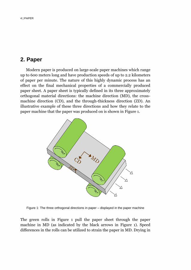
paper sheet. A paper sheet is typically defined in its three approximately
orthogonal material directions: the machine direction (MD), the cross-
machine direction (CD), and the through-thickness direction (ZD). An
illustrative example of these three directions and how they relate to the
paper machine that the paper was produced on is shown in Figure 1.
Figure 1: The three orthogonal directions in paper – displayed in the paper machine
The green rolls in Figure 1 pull the paper sheet through the paper
machine in MD (as indicated by the black arrows in Figure 1). Speed
differences in the rolls can be utilized to strain the paper in MD. Drying in

PAPER | 5
such a strained condition (i.e. restraint drying) can create an increased
stiffness and strength in MD.
Paper is a composite material composed of fibers (each of which is a
multi-layer composite material composed of cellulose, hemicellulose, and
lignin [9]), fines (a non-homogeneous collection of particles, including
bands, flakes, and ray cells [10]), and pores. However, the fibers
themselves are the primary load-carrying part of the structure. Tree-
based fibers typically have lengths from 1 to 5 mm, widths from 10 to 40
µm, wall thicknesses from 2 to 10 µm, and hollow oval cross-sections.
However, during the drying part of the papermaking process, the hollow
oval cross-sections of these tree fibers typically collapse. These fibers are
quasi-randomly distributed throughout the sheet structure, and most
fibers are oriented within the in-plane (MD-CD) directions. Within the
in-plane (MD-CD) directions, fibers tend to have a bias towards MD; this
orientation causes MD to typically be stiffer and stronger than CD.
In the ZD direction, the fiber-fiber joints are the primary tensile-load-
carrying structure. In ZD tension, these joints are much weaker and more
compliant than the stiffness of the fibers for in-plane loading. In ZD
compression, the material response is driven by compression of the
fibers. The fibers are much more compliant in ZD compression than they
are during in-plane loading. Generally, the stiffness of paper in the in-
plane (MD-CD) directions is typically at least a magnitude of ten times
greater than the stiffness in the out-of-plane directions [11], making paper
a highly anisotropic material. This significant difference between the in-
plane (MD-CD) and out-of-plane stiffness is a primary reason why an in-
plane plasticity model with out-of-plane elasticity is utilized in this work.
The subsequent sub-sections present the specific types of paper
materials utilized in this work, including kraft fiber handsheets, kraft
fiber handsheets with fibers partially oxidized to dialcohol cellulose, and
commercial paperboard.
2.1. Kraft Fiber Handsheets
In Papers A & E, handsheets produced from Celeste kraft pulp from
SCA (Svenska Cellulosa Aktiebolaget) were utilized. This pulp was beaten
at 160 kWh/t, and the handsheets were made with white water
recirculation on the Rapid Köthen laboratory sheet former in the
Department of Fibre and Polymer Technology at KTH Royal Institute of
Technology. This beating level in conjunction with white water
recirculation provided the best strain-at-break properties for this pulp.
High strain-at-break properties were desired in order to provide the best
possible 3-D formability. The same beaten pulp was utilized in the
investigation of the 3-D formability of chemically modified paper
materials as is described in the following section.

6 | PAPER
2.2. Kraft Fiber Handsheets with Fibers Partially Oxidized
to Dialcohol Cellulose
In Paper F, the same beaten kraft pulp was utilized as in Papers A & E.
Prior to the handsheet-making process, the fibers in the pulp were
partially oxidized to dialcohol cellulose [12]. The purpose of the
modification was to dramatically increase the strain-at-break and thus 3-
D formability of the handsheets.
2.3. Paperboard
Paperboard is a type of paper which often consists of multiple layers.
The utilization of multiple layers allows one to optimize the bending
strength, print surface, and appearance. A visual representation of one
type of paperboard construction is provided in Figure 2.
Figure 2: Multi-layer paperboard construction
Typically, the outer layers of paperboard, which are represented by the
brown, thinner layers in Figure 2, have stiffer fibers with better
appearance properties than the middle layer, which is represented by the
green, thicker layer in Figure 2. The middle layer is typically bulkier and
more compliant than the outer layers, because the middle layer has less
effect on the bending stiffness. Additionally, since the middle layer is
hidden from view, the middle layer typically does not have to meet any
visual requirements.
The experimental study of the biaxial in-plane yield and failure
surfaces in Paper B utilized paperboard, because the thicker grades of

PAPER | 7
paperboard are sufficiently thick for utilization with laser engraving. The
paperboard utilized in Paper B had a thickness of 0.7 mm.
Due to the effectiveness of paperboard as a packaging material and its
superior visual quality, Papers C & D focus on the deep-drawing of
paperboard. Trayforma 350 from Stora Enso was selected for both studies
of deep-drawing. Unpublished experimental experience at TU Dresden
has shown that Trayforma 350 performs well in the deep-drawing
process.
2.4. Paper versus Other Packaging Materials
Paper materials are typically not as 3-D formable as other traditional
packaging materials such as some types of plastic or aluminum. However,
paper materials have many advantages as compared to other packaging
materials, and a comparison between paperboard and other typical
packaging materials is provided in Table 1.

8 | PAPER
Table 1: Comparison between paperboard and other typical packaging materials (many values are estimated from the provided references)
Es
tim
ate
d
FO
B C
os
t E
ffic
ien
cy
(c
os
t/m
as
s)
(US
D k
g-1
)
1.1
(sh
eet
)
1.1
(sh
eet
)
0.5
(b
ott
le)
2.5
(sh
eet)
1.4
(g
ran
ule
)
1.6
(g
ran
ule
)
Str
en
gth
E
ffic
ien
cy
(σ
y/ρ)
(N m
g-1
) [1
6][
17
] [1
8]
59
(M
D)
32
(C
D)
84
(M
D)
40
(C
D)
3
25
9
33
Sti
ffn
es
s
Eff
icie
nc
y
(E/ρ)
(kN
m g
-1)
[16
] [1
7]
[18
]
7 (
MD
) 5
(C
D)
9 (
MD
) 3
(CD
)
26
25
1 2
Re
cy
cli
ng
F
re
qu
en
cy
(T
ota
l) i
n
US
A 2
016
(%
by
w
eig
ht)
[1
5]
67
67
34
55
28
31
Re
cy
cli
ng
F
re
qu
en
cy
(P
ac
ka
gin
g)
in S
we
de
n
20
15
(%
by
w
eig
ht)
[14
]
80
80
94
73
40
40
Ty
pic
al
De
co
mp
os
itio
n
Tim
e i
n M
ar
ine
E
nv
iro
nm
en
t (y
ea
rs
) [1
3]
0.2
5
0.2
5
100
00
00
140
25
45
0
Ma
ter
ial
Pa
per
bo
ard
(T
ray
form
a 3
50
)
Pa
per
bo
ard
(I
nv
erco
te G
35
0)
Bo
rosi
lica
te
Gla
ss
Alu
min
um
(3
00
4)
Pla
stic
(H
DP
E)
Pla
stic
(P
ET
)

EXPERIMENTAL MECHANICAL CHARACTERIZATION | 9
3. Experimental Mechanical Characterization
The subsequent sub-sections present the experimental techniques
developed as well as key results obtained for the two experimental studies
conducted during this work: the combined effects of moisture and
temperature on the mechanical response of paper handsheets, and the
biaxial failure and yield of paperboard.
3.1. The Effects of Moisture and Temperature
The constitutive behavior of paper materials is known to be sensitive
to both moisture and temperature, and Paper A contains a review of
published papers on the effects of moisture and temperature.
The definition of the moisture content can vary, but a consistent
definition of moisture content has been utilized throughout this work as
follows:
𝑚𝑐 =𝑀𝑚𝑜𝑖𝑠𝑡𝑢𝑟𝑒
𝑀𝑡𝑜𝑡 (1)
where 𝑚𝑐 is the moisture content, 𝑀𝑚𝑜𝑖𝑠𝑡𝑢𝑟𝑒 is the mass of moisture
contained within the paperboard, and 𝑀𝑡𝑜𝑡 is the total mass of the
paperboard including the moisture.
A new experimental setup was created in Paper A to study the
combined effects of moisture and temperature on the uniaxial, tensile
mechanical response of paper. The same experimental setup was utilized
in Paper F to study the combined effects of moisture and temperature on
the mechanical response of chemically modified paper. The experimental
setup utilized pre-conditioning of samples at a given relative humidity
and heating of the samples with a heating lamp during the tensile test.
In Paper A, moisture and temperature was found to have uncoupled
effects on the elastic modulus, tangent modulus, hardening modulus,
strain-at-break, and tensile energy absorption. In Paper F, moisture and
temperature was found to have uncoupled effects on all parameters
studied (i.e. elastic modulus, tangent modulus, and yield strength). In this

10 | EXPERIMENTAL MECHANICAL CHARACTERIZATION
context, uncoupled effects means that only three (as opposed to four)
coefficients are required to calculate the material property at a given
moisture content and temperature (within the studied ranges). See
Papers A & F for further discussion of the definition of coupled or
uncoupled effects.
The following hyperbolic tangent function was utilized to fit the tensile
test data:
𝜎 = 𝐶1 tanh(𝐶2𝜀) + 𝐶3 𝜀 (2)
where 𝜎 is the stress, 𝐶1−3 are curve-fitting constants, and 𝜀 is the total
strain. This hyperbolic tangent function fit all experimental results in
Papers A & F with an R-squared value of greater than 0.98, and
utilization of this hyperbolic tangent function allowed for systematic,
simple, and unbiased determination of material properties and the effects
of moisture and temperature on those material properties.
3.2. Biaxial Failure and Yield
The biaxial failure and yield of paper materials was directly (i.e.
experimentally) studied in Paper B and indirectly (i.e. combining
experimental and numerical methods) in Paper F. This section, however,
presents complete in-plane failure surfaces at zero in-plane shear stress
for different materials and utilizes those surfaces to analyze the 3-D
formability of the respective materials.
The experimental biaxial study in Paper B determined, among many
other conclusions, that the shapes of the yield and failure surfaces are
similar. This similarity, along with the assumption of a maximum stress
yield surface (discussed in more detail in Section 4.1), allows for direct
estimation of the strain-based failure surface (i.e. forming limit diagram)
from the uniaxial results, as conducted in Paper F. For an orthotropic
material with a maximum stress yield surface and zero in-plane shear
stress, the strain-based failure surface can be assumed to be composed of
the four following linear equations:
𝜀𝐶𝐷 = −ν𝑀𝐷−𝐶𝐷𝜀𝑀𝐷 + 𝜀𝐶𝐷,𝑓,𝑡(1 − ν𝑀𝐷−𝐶𝐷2) (3)
𝜀𝐶𝐷 = −ν𝑀𝐷−𝐶𝐷𝜀𝑀𝐷 + 𝜀𝐶𝐷,𝑓,𝑐(1 − ν𝑀𝐷−𝐶𝐷2) (4)
𝜀𝐶𝐷 = −1
ν𝐶𝐷−𝑀𝐷𝜀𝑀𝐷 + 𝜀𝑀𝐷,𝑓,𝑡 (
1
ν𝐶𝐷−𝑀𝐷− ν𝐶𝐷−𝑀𝐷) (5)
𝜀𝐶𝐷 = −1
ν𝐶𝐷−𝑀𝐷𝜀𝑀𝐷 + 𝜀𝑀𝐷,𝑓,𝑐 (
1
ν𝐶𝐷−𝑀𝐷− ν𝐶𝐷−𝑀𝐷) (6)
where 𝜀𝐶𝐷 and 𝜀𝑀𝐷 are respectively the CD and MD strains, ν𝑀𝐷−𝐶𝐷 and
ν𝐶𝐷−𝑀𝐷 are the Poisson’s ratios during tensile loading respectively in CD

EXPERIMENTAL MECHANICAL CHARACTERIZATION | 11
and MD, 𝜀𝐶𝐷,𝑓,𝑡 and 𝜀𝐶𝐷,𝑓,𝑐 are respectively the tensile and compressive CD
strain-at-break, and 𝜀𝑀𝐷,𝑓,𝑡 and 𝜀𝑀𝐷,𝑓,𝑐 are respectively the tensile and
compressive MD strain-at-break. Strain-based failure surfaces generated
from (3)-(6) for four different materials (i.e. reference handsheets,
chemically modified handsheets, Trayforma commercial paperboard, and
Invercote G commercial paperboard) are shown in Figure 3 and Figure 4.
Interpretations of the strain-based failure surface for various 3-D forming
operations are provided in Figure 5 and Paper B. For reference, Figure 5
also includes the strain path for tensile loading in MD and CD, which are
respectively represented by blue and purple/magenta lines.
Figure 3: Estimated strain-based failure surfaces (zero shear strain) for different materials at 100 °C

12 | EXPERIMENTAL MECHANICAL CHARACTERIZATION
Figure 4: Estimated strain-based failure surfaces (zero shear strain) for different materials at 100 °C, zoomed in on materials without chemical modification
Figure 5: Interpretation of the strain-based failure surface for 3-D forming, where the red/brown area represents possible initiation of wrinkling

MATERIAL MODELS | 13
4. Material Models
Material models were developed in order to capture permanent
deformations during the simulated 3-D forming processes in Papers C-F.
The foundation of these models is based on the assumption of orthotropic
material directions with in-plane (MD-CD), linear, quadrant hardening.
Quadrant hardening is the name given to hardening which only affects
the parts of the yield surface that enter the quadrant of the current
normal stress state.
The material properties were assumed to be affected by temperature
and moisture based on the experimental method in Paper A and
experimental results in Papers A & F.
The subsequent sub-sections provide: an overview of the orthotropic
elastic-plastic model with in-plane (MD-CD), linear, quadrant hardening,
an overview of the inclusion of wrinkle development and compression in
a continuum method, and a presentation of the utilized validations of
these models.
4.1. Orthotropic Elastic-Plastic Model
A few key assumptions were utilized to derive the in-plane quadrant
hardening model:
1. Orthotropic material behavior
2. No coupling between in-plane (MD-CD) and out-of-plane
behavior
3. In-plane maximum stress yield surface with quadratic
dependency on in-plane (MD-CD) shear stress
4. In-plane (MD-CD) linear quadrant (anisotropic) hardening
5. Linear elastic out-of-plane behavior
Paper C presents and discusses these assumptions. Although many of the
assumptions listed above are common for paper materials, this section

14 | MATERIAL MODELS
introduces those parts that are unique to this model (i.e. quadrant
hardening and the yield surface).
Due to the extensive experimental scatter in the yield point, a simple
stress-based yield surface was chosen: an in-plane (MD-CD) maximum
normal stress yield surface with quadratic dependence on the in-plane
shear stress. This surface is supported by the stress-based yield surface
obtained in Paper B as well as by the stress-based failure surface obtained
by Suhling et al. [19] (which exhibited quadratic dependence on in-plane
shear stress). The selected stress-based yield surface is shown in Figure 6.
Bisections of the stress-based yield surface at constant in-plane shear
stresses are projected onto a contour map in Figure 6.
Figure 6: Yield surface for an in-plane (MD-CD) stress state
At zero in-plane shear stress, Figure 6 becomes the two-dimensional yield
surface with four sub-surfaces in Figure 7. The four subsurfaces can be
described by:
𝑘𝑖 =𝜎𝑖
𝜎𝑦𝑖
+ (𝜏
𝜏𝑦)
2
(7)
where 𝑘𝑖 begins at a value of unity and expands with the yield surface for
each independent sub-surface, 𝜏 is the in-plane (MD-CD) shear stress
state, 𝜏𝑦 is the in-plane (MD-CD) shear yield stress, and 𝜎𝑖 and 𝜎𝑦𝑖 are
defined in Table 2.

MATERIAL MODELS | 15
Figure 7: Yield surface for a value of in-plane (MD-CD) shear stress
Table 2: Definition of the normal stress terms in (7)
𝒊 𝝈𝒊 𝝈𝒚𝒊
1 Tensile MD Stress Initial Tensile MD Yield Stress
2 Tensile CD Stress Initial Tensile CD Yield Stress
3 Compressive MD Stress Initial Compressive MD Yield Stress
4 Compressive CD Stress Initial Compressive CD Yield Stress
The anisotropic (non-associative) hardening behavior utilized in this
model was supported by experimental evidence in Paper C, in which
purely tensile loading in MD or CD only caused changes in the yield
surface in MD or CD respectively. Since paper is a fibrous material, small-
deformation plastic straining in one direction would likely not cause
plastic straining in an orthotropic direction. Conflicting evidence for this
assumption was found by Borgqvist et al. [20] utilizing a different
experimental method. However, the experimental method utilized by
Borgqvist et al. [20] subjected the specimens to biaxial loads (i.e. not
purely tensile loads) during the pre-stress portion of the experiments due
to the test piece dimensions (i.e. 160 mm wide and 145 mm between the
clamps), which could have significant effect on the results.
Quadrant hardening was chosen as the anisotropic (non-associative)
hardening behavior, and quadrant hardening means that the expansion of
the yield surface only occurs for those parts of the yield surfaces lying in
the same quadrant as the normal stress state. For example, in bi-axial
16 | MATERIAL MODELS
tension, only sub-surfaces 1 and 2 in Figure 7 expand. Because the
hardening behavior utilizes a non-associative plastic flow potential, the
corners of the yield surface shown in Figure 6 and Figure 7 do not affect
the solution uniqueness as would an associative plastic flow potential.
One property of quadrant hardening is that any loading in purely MD
or CD only causes yielding (i.e. change of the yield surface) in the
respective direction. This property means that transitions between
quadrants are continuous.
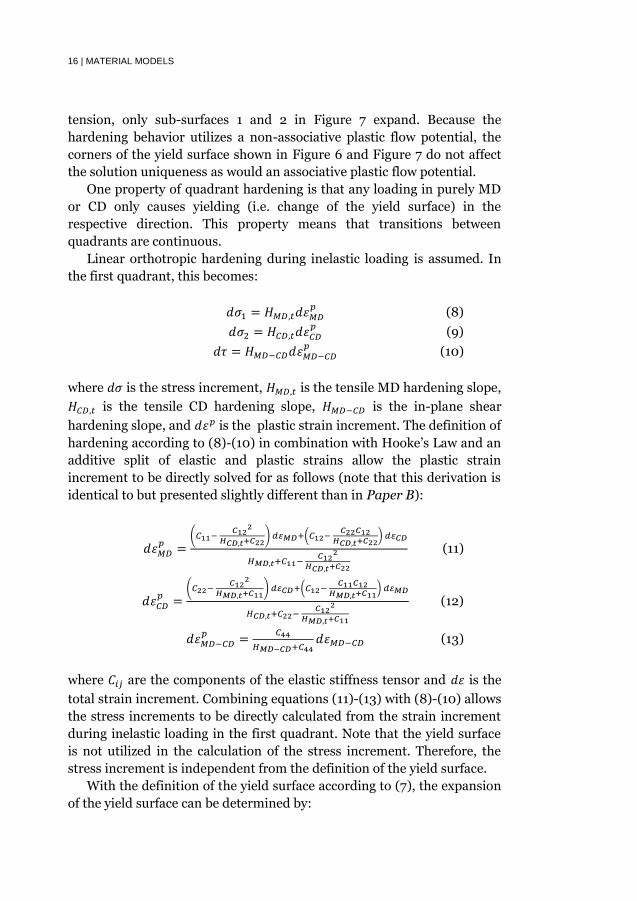
Linear orthotropic hardening during inelastic loading is assumed. In
the first quadrant, this becomes:
𝑑𝜎1 = 𝐻𝑀𝐷,𝑡𝑑𝜀𝑀𝐷𝑝
(8)
𝑑𝜎2 = 𝐻𝐶𝐷,𝑡𝑑𝜀𝐶𝐷𝑝
(9)
𝑑𝜏 = 𝐻𝑀𝐷−𝐶𝐷𝑑𝜀𝑀𝐷−𝐶𝐷𝑝
(10)
where 𝑑𝜎 is the stress increment, 𝐻𝑀𝐷,𝑡 is the tensile MD hardening slope,
𝐻𝐶𝐷,𝑡 is the tensile CD hardening slope, 𝐻𝑀𝐷−𝐶𝐷 is the in-plane shear
hardening slope, and 𝑑𝜀𝑝 is the plastic strain increment. The definition of
hardening according to (8)-(10) in combination with Hooke’s Law and an
additive split of elastic and plastic strains allow the plastic strain
increment to be directly solved for as follows (note that this derivation is
identical to but presented slightly different than in Paper B):
𝑑𝜀𝑀𝐷𝑝
=(𝐶11−
𝐶122
𝐻𝐶𝐷,𝑡+𝐶22) 𝑑𝜀𝑀𝐷+(𝐶12−
𝐶22𝐶12𝐻𝐶𝐷,𝑡+𝐶22
) 𝑑𝜀𝐶𝐷
𝐻𝑀𝐷,𝑡+𝐶11− 𝐶12
2
𝐻𝐶𝐷,𝑡+𝐶22
(11)
𝑑𝜀𝐶𝐷𝑝
=(𝐶22−
𝐶122
𝐻𝑀𝐷,𝑡+𝐶11) 𝑑𝜀𝐶𝐷+(𝐶12−
𝐶11𝐶12𝐻𝑀𝐷,𝑡+𝐶11
) 𝑑𝜀𝑀𝐷
𝐻𝐶𝐷,𝑡+𝐶22− 𝐶12
2
𝐻𝑀𝐷,𝑡+𝐶11
(12)
𝑑𝜀𝑀𝐷−𝐶𝐷𝑝
=𝐶44
𝐻𝑀𝐷−𝐶𝐷+𝐶44𝑑𝜀𝑀𝐷−𝐶𝐷 (13)
where 𝐶𝑖𝑗 are the components of the elastic stiffness tensor and 𝑑𝜀 is the
total strain increment. Combining equations (11)-(13) with (8)-(10) allows
the stress increments to be directly calculated from the strain increment
during inelastic loading in the first quadrant. Note that the yield surface
is not utilized in the calculation of the stress increment. Therefore, the
stress increment is independent from the definition of the yield surface.
With the definition of the yield surface according to (7), the expansion
of the yield surface can be determined by:
MATERIAL MODELS | 17
𝑑𝑘1 =𝑑𝜎1
𝜎𝑦1
+2𝜏𝑑𝜏
𝜏𝑦2 (14)
𝑑𝑘2 =𝑑𝜎2
𝜎𝑦2
+2𝜏𝑑𝜏
𝜏𝑦2 (15)
where 𝑑𝑘 is the change in the size of the yield surface.
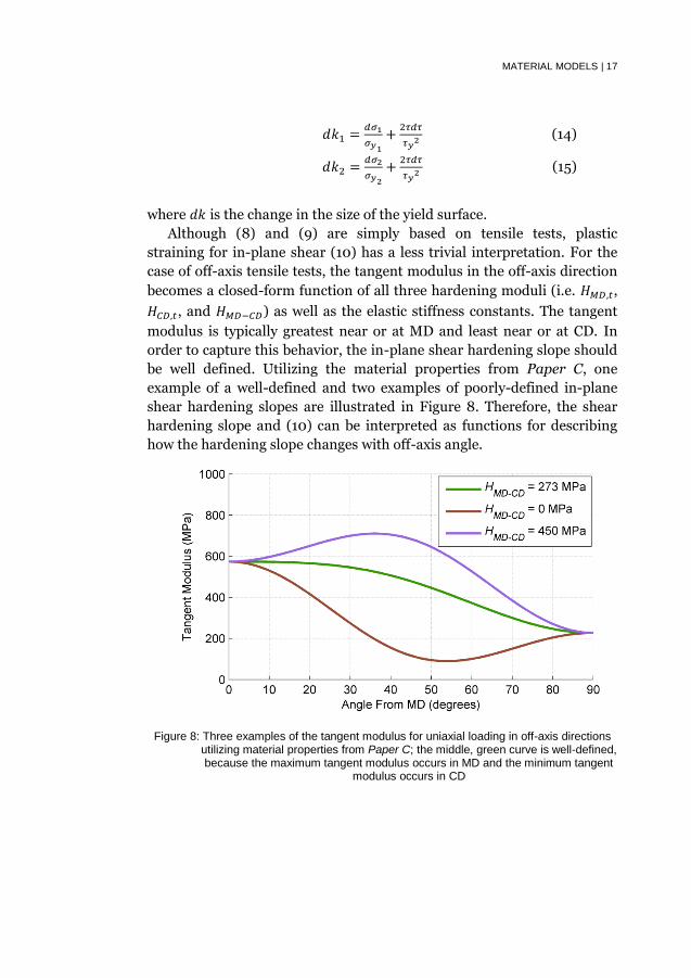
Although (8) and (9) are simply based on tensile tests, plastic
straining for in-plane shear (10) has a less trivial interpretation. For the
case of off-axis tensile tests, the tangent modulus in the off-axis direction
becomes a closed-form function of all three hardening moduli (i.e. 𝐻𝑀𝐷,𝑡,
𝐻𝐶𝐷,𝑡, and 𝐻𝑀𝐷−𝐶𝐷) as well as the elastic stiffness constants. The tangent
modulus is typically greatest near or at MD and least near or at CD. In
order to capture this behavior, the in-plane shear hardening slope should
be well defined. Utilizing the material properties from Paper C, one
example of a well-defined and two examples of poorly-defined in-plane
shear hardening slopes are illustrated in Figure 8. Therefore, the shear
hardening slope and (10) can be interpreted as functions for describing
how the hardening slope changes with off-axis angle.
Figure 8: Three examples of the tangent modulus for uniaxial loading in off-axis directions utilizing material properties from Paper C; the middle, green curve is well-defined, because the maximum tangent modulus occurs in MD and the minimum tangent
modulus occurs in CD

18 | MATERIAL MODELS
4.2. Wrinkling in the Continuum
Paper D introduces a constitutive model for wrinkled paperboard in
the continuum, including large deformation and size effects. Wrinkled
paperboard is assumed to have a response equal to that of a perfectly
plastic hinge (i.e. the moment in the hinge is constant during permanent
deformation), which was validated for three types of paperboard and a
variety of simple experiments. The reader is directed to Paper D to learn
the details of the model and the validation.
This section specifically examines the wrinkling point in order to
provide a physical interpretation of the hinge yield strength, which is the
material property that determines the mechanical response of wrinkled
paperboard. The expression for the wrinkling point is given by the one-
dimensional equation in the direction of minimum in-plane principal
stress:
𝜀ℎ2 =
𝜎ℎ,𝑦
2𝐸ℎ(1 + 𝑒−2𝜀ℎ√1 − 𝑒2𝜀ℎ + tan−1(1 − 𝑒2𝜀ℎ) − 𝑒−2𝜀ℎ) (16)
where 𝜀ℎ is the hinge strain (i.e. a negative number), 𝜎ℎ,𝑦 is the hinge yield
strength (i.e. the material property defining the mechanical response of
the wrinkles), and 𝐸ℎ is the elastic stiffness in the direction of wrinkle
compression. From this expression, the effect of the elastic and hinge
material properties on the wrinkle initiation strain can directly be solved,
and the result is shown in Figure 9.
Figure 9: Compressive wrinkle initiation strain as a function of material properties
MATERIAL MODELS | 19
As is clearly illustrated in Figure 9, lesser hinge yield strengths result
in wrinkling at lower levels of strain. Alternatively, greater hinge yield
strengths result in wrinkle initiation at greater compressive strains.
Therefore, the hinge yield strength provides information about the
resistance to initiation and subsequent compression of wrinkles.
Generally, deep-drawn paperboard cups with greater number of
wrinkles have a better visual quality than the deep-drawn cups with lesser
number of wrinkles [21], thus implying that lower hinge yield strength
could be beneficial. However, paperboard is far from homogeneous, and
deviations in hinge yield strength would cause greater deviations in
wrinkle initiation strain at lesser hinge yield strengths than at greater
hinge yield strengths, as shown in Figure 9. An important quality
parameter for deep-drawn paperboard cups is the evenness of wrinkling
[21]. Therefore, the optimal hinge yield strength for deep-drawing would
fulfill two criteria: constant ratio (𝜎ℎ,𝑦 𝐸ℎ⁄ ) between hinge yield strength
and elastic modulus for all in-plane directions and smallest deviations of
that ratio.
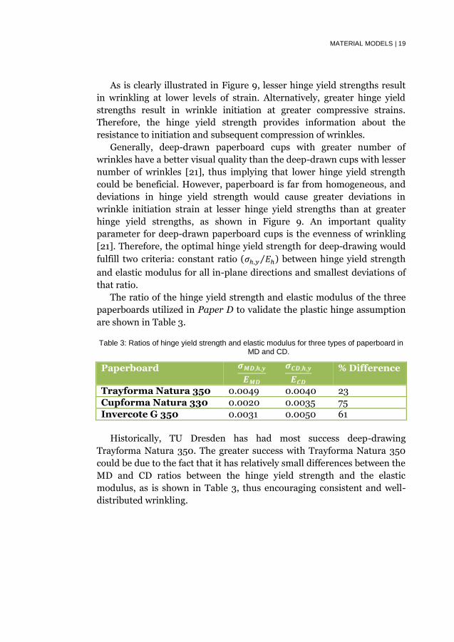
The ratio of the hinge yield strength and elastic modulus of the three
paperboards utilized in Paper D to validate the plastic hinge assumption
are shown in Table 3.
Table 3: Ratios of hinge yield strength and elastic modulus for three types of paperboard in MD and CD.
Paperboard 𝝈𝑴𝑫,𝒉,𝒚
𝑬𝑴𝑫
𝝈𝑪𝑫,𝒉,𝒚
𝑬𝑪𝑫
% Difference
Trayforma Natura 350 0.0049 0.0040 23
Cupforma Natura 330 0.0020 0.0035 75
Invercote G 350 0.0031 0.0050 61
Historically, TU Dresden has had most success deep-drawing
Trayforma Natura 350. The greater success with Trayforma Natura 350
could be due to the fact that it has relatively small differences between the
MD and CD ratios between the hinge yield strength and the elastic
modulus, as is shown in Table 3, thus encouraging consistent and well-
distributed wrinkling.

20 | MATERIAL MODELS
4.3. Validation
In addition to presenting the material model, Papers C-F include also
validation of the utilized material models. These methods included:
Off-axis tensile testing (Paper C)
Tensile testing the anisotropic hardening (Paper C)
Three-point bending tests (Paper C)
Compressive testing of the plastic hinge assumption (Paper D)
Tensile testing of wrinkled paperboard (Paper D)
Off-axis tensile testing of wrinkled paperboard (Paper D)
Deep drawing
o Punch force (Papers C & D)
o Wrinkle number (Paper D)
o Springback and its asymmetry (Paper D)
Hydroforming (Papers E & F)
o Final forming depth (Papers E & F)
o Final forming volume (Paper E)
o Failure (Paper F)
The model was capable of matching well the experimental results with the
exception of predicting the bending response of paperboard in MD and
obtaining precise values for the 3-D forming processes. Validation of the
model in bending was carried out for a paperboard material. The
continuum model did not account for the composite structure of
paperboard which maximizes bending stiffness as illustrated in Figure 2,
which is why the model underestimated the bending stiffness. The
comparison between the simulated and experimental deep drawing and
hydroforming of paper materials was capable of showing that the model
captured the trends and approximate values for the respective processes.
The minor differences between simulations and experimental forming are
not surprising, because these 3-D forming processes consist of numerous
relatively unknown process parameters (e.g. coefficients of friction) and
tend to exhibit significant experimental variability. Therefore, the extent
to which these 3-D forming processes can be utilized to validate the
material model is somewhat limited.

3-D FORMING OF PAPER | 21
5. 3-D Forming of Paper
3-D forming of paper materials is defined as the production of
advanced, 3-D paper structures without utilizing traditional creasing and
folding techniques.
Traditional paper-based packaging products are mostly limited to
folded box structures or sacks. In other words, traditional paper-based
packaging tends to have a limited package shape. Especially when
compared to other packaging materials (e.g. plastics and aluminum
alloys), paper is limited in the extent to which it can be formed into
advanced, 3-D structures. The development of 3-D forming techniques
specifically designed for paper materials, however, could increase the
number of possible paper-based packages and thus increase the
competitiveness of paper-based packaging.
Vishtal [22] introduced a useful classification system for
distinguishing 3-D forming processes into two groups: sliding blank and
fixed blank processes. A sliding blank process is a process during which
the blank (i.e. the paper specimen) is allowed to slide in between the die
and blankholder. A fixed blank process is a process during which the
blank is held in place between the die and blankholder. Some types of 3-D
forming processes for paper materials are presented in Table 4.
Table 4: Types of 3-D forming processes for paper materials
Sliding Blank Fixed Blank
Deep Drawing Hydroforming
Stamping/Press Forming Blow/Vacuum Forming
Of the four processes shown in Table 4, deep drawing and hydroforming
were selected as the focus of this work. The deep-drawing process is
currently one of the most developed 3-D forming processes for traditional
paper materials and is even currently utilized in limited commercial
processes. Recent research and development of this process at TU
Dresden has realized a significant new potential for this process [23]-
[24], although improved understanding of the effects of material

22 | 3-D FORMING OF PAPER
properties and process parameters on quality measures for deep-drawn
paperboard cups (e.g. failure probability [25], springback, and wrinkle
distribution and number [21]) are necessary. Because experimental
determination of the effects on these quality measures has been difficult,
this work has studied these quality measures utilizing an explicit finite
element approach.
As opposed to the sliding blank processes in Table 4 for which
matching dies and blanks must be simultaneously produced for each
different 3-D packaging shape, the fixed blank processes in Table 4
require only one die to be produced for each shape. The paper blank in
blow/vacuum forming is directly subjected to an air pressure differential,
but the effectiveness of this pressure differential depends on the porosity
of the material. During hydroforming, on the other hand, a membrane
(e.g. rubber) is utilized to engage the pressure differential and transmit
the load from this pressure differential to the blank. Due to the porous
nature of paper materials and the simplicity of creating tooling for fixed
blank processes, the hydroforming process was also investigated in this
work.
The subsequent sub-sections respectively present and discuss the
deep-drawing and hydroforming processes.
5.1. Deep Drawing
The deep-drawing process is illustrated in Figure 10.
Figure 10: Sketch of the deep-drawing process
During the deep-drawing process, the blank is held between the
blankholder and die, and the punch travels downwards. As the punch
pulls the blank through the die, the blank slides between the blankholder
and the die. As the blank is drawn deeper into the die, the large
3-D FORMING OF PAPER | 23
compressive circumferential forces cause the blank to wrinkle. Precise
control over the force provided by the blankholder can be utilized to affect
the size and distribution of these wrinkles for paper materials. As defined
by Hauptmann and Majschak [23], a greater number of small wrinkles
(with a length scale on the range of hundreds of micrometers) are
preferable for maximizing visual quality.
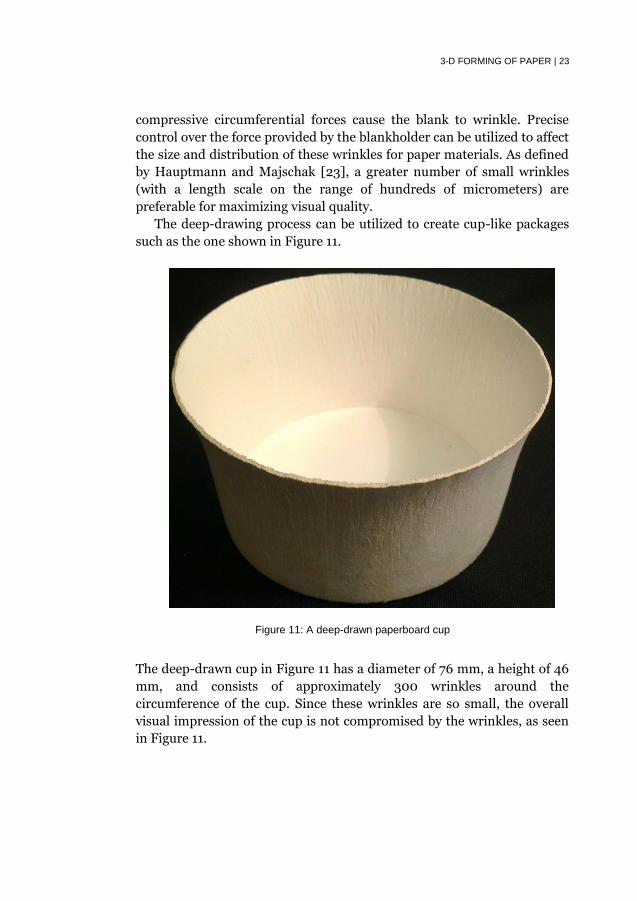
The deep-drawing process can be utilized to create cup-like packages
such as the one shown in Figure 11.
Figure 11: A deep-drawn paperboard cup
The deep-drawn cup in Figure 11 has a diameter of 76 mm, a height of 46
mm, and consists of approximately 300 wrinkles around the
circumference of the cup. Since these wrinkles are so small, the overall
visual impression of the cup is not compromised by the wrinkles, as seen
in Figure 11.

24 | 3-D FORMING OF PAPER
5.2. Hydroforming
The hydroforming process is illustrated in Figure 12.
Figure 12: Sketch of the hydroforming process
During the hydroforming process, the blank is held in place between the
blankholder and die, and a pressure is applied within the balloon. This
pressure is then applied to the blank, forcing the blank to deform into the
shape of the die. The main purpose of this 3-D forming technique is to
create permanent (i.e. plastic) tensile in-plane (MD-CD) deformation in
the paper blank. Wrinkling is typically avoided during hydroforming for
both sealing and visual purposes. One could induce wrinkle formation in
the hydroforming process by allowing increased sliding of the blank into
the die, but this would also require precision control of the blankholder.
The hydroforming process can create complex double-curved surfaces,
such as the donut-shaped structure created with hydroforming shown in
Figure 13, which has a width of 15 cm and a formed depth of 3 cm.
Figure 13: A donut-shaped paper structure created with hydroforming

MODELS OF 3-D FORMING OF PAPER | 25
6. Models of 3-D Forming of Paper
Simulations of deep-drawing and hydroforming of paper materials
were conducted utilizing LS-DYNA, a commercial explicit finite element
solver. The developed material models presented in Section 4 were
implemented into the LS-DYNA user-defined material subroutine. Due to
the approximately orthotropic nature of paper, quarter symmetry was
utilized in all 3-D forming models utilized in Papers C-F. The subsequent
sub-sections summarize the major findings of the parametric studies
from Papers C-D (i.e. studies of deep drawing) and Paper E (i.e. study of
hydroforming). Furthermore, visual comparisons between experimental
and simulated 3-D formed paper structures are also provided.
6.1. Deep Drawing
Paper C utilized explicit finite element simulations to investigate the
effects of various process parameters on the punch force up to the
wrinkling point. The punch force was investigated, because the punch
force is related to the probability of failure [25]. Friction was especially
identified as a very important parameter for controlling the probability of
failure during the deep-drawing process (e.g. reduced friction would
reduce the probability of failure during the process).
Paper D, which utilized the material model with wrinkling in the
continuum, allowed for explicit finite element simulation of the entire
deep-drawing process and thus the study of many other quality
requirements or validation measures (e.g. springback and number of
wrinkles) for the deep-drawing process. The effects of various material
and process parameters on three different quality measures (i.e.
probability of failure, ovality, and average springback) were numerically
studied, and the hinge yield strength (𝜎ℎ,𝑦) was identified as the only
material parameter which could simultaneously improve all three studied
quality measures. A visual comparison between the simulated and
experimental deep-drawn paperboard cups is shown in Figure 14.

26 | MODELS OF 3-D FORMING OF PAPER
Figure 14: Simulated (pink elements are wrinkled while white elements are non-wrinkled) and experimental deep-drawn paperboard cup
6.2. Hydroforming
Paper E utilized explicit finite element simulations to investigate the
effects of various process and material parameters on the final volume of
the formed shape. Both the blankholder force and relative humidity were
found to have negligible effect on the final formed volume. The
blankholder force had no significant effect, because little to no sliding of
the blank occurred during all simulations regardless of the blankholder
force. Changes in relative humidity, however, cause changes in the
stiffness, yield point, and tangent modulus of the paper. For some reason
(possibly only for the specific material utilized in Paper E), the effects of
the changed stiffness, yield point, and tangent modulus happened to
cancel in their combined effects on the increase in final formed volume.
For reasonable changes in elastic stiffness, the increase in final formed
volume showed an approximately linear positive relationship with
stiffness. However, for stiffness greater than 9 GPa (such as the doubled
elastic stiffness in Paper E), drastic reductions in the forming volume
were obtained.
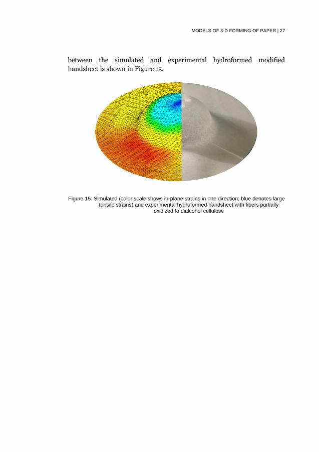
Paper F utilized explicit finite element simulations to investigate the
3-D formability and assumed strain-based failure surface of handsheets
with fibers partially oxidized to dialcohol cellulose. A visual comparison
MODELS OF 3-D FORMING OF PAPER | 27
between the simulated and experimental hydroformed modified
handsheet is shown in Figure 15.
Figure 15: Simulated (color scale shows in-plane strains in one direction; blue denotes large tensile strains) and experimental hydroformed handsheet with fibers partially
oxidized to dialcohol cellulose
28 | CONCLUSIONS
7. Conclusions
The three overarching research questions investigated in this work
(from Section 1.1) can be split into five specific sub-questions that were
addressed through this work:
1. How 3-D formable are paper materials?
a. What is the strain-based failure surface (i.e. forming
limit diagram) for paper materials?
b. What are the effects of moisture and temperature on
3-D formability?
2. How can paper materials be improved for specific 3-D
forming processes?
a. Which material properties are important for
hydroforming and deep drawing of traditional paper
materials?
b. How can the 3-D formability of paper materials be
improved through chemical modification?
3. How can specific 3-D forming processes for paper materials be
improved?
a. Which process parameters are important for
hydroforming and deep drawing of traditional paper
products?
The strain-based failure surface (question 1a) for paperboard and
handsheets with fibers partially oxidized to dialcohol cellulose were
experimentally and numerically explored in Papers B & F. Paper B found
that a part of the strain-based failure surface could be represented by a
bilinear surface. Furthermore, Paper B shows the limited extent to which
traditional paper materials can be formed in biaxial tension (e.g.
hydroforming or embossing). However, Paper B does indicate an increase
of the strain-at-break in sliding blank processes during which
compressive in-plane forces appear (e.g. deep drawing or press forming).
Paper F, on the other hand, developed a method to estimate the strain-

CONCLUSIONS | 29
based failure surface based on uniaxial testing results and validated that
method utilizing the finite element method. The handsheets utilized in
Paper F had fibers that were partially oxidized to dialcohol cellulose, and
the achieved forming limit diagrams in Paper F show the possible
improvement of 3-D formability by means of chemical modification
(question 2b).
The effects of moisture and temperature on 3-D formability (question
1b) were experimentally and numerically explored in Papers A, & D-F. In
Paper A, an experimental method was developed to enable the systematic
study of the combined effects of moisture and temperature on the
mechanical response of paper. This experimental method was applied to
chemically modified handsheets in Paper F, although Paper F also
utilized dynamic mechanical thermal analysis to study the glass transition
temperature (as a function of humidity) as well as to study the viscous
part of the mechanical response. The mechanical testing results from
both papers contain insights into the effects of moisture and temperature
on the materials and provide constitutive parameters that were utilized
for explicit FEM simulations in Papers C-F. The parametric studies
utilizing explicit FEM simulations in Papers D & E further quantified the
effects of moisture and temperature on three quality parameters (i.e.
average springback, springback asymmetry, and final formed volume) for
3-D forming.
The effects of various material properties on the hydroforming and
deep drawing of paper materials (question 2a) were numerically explored
and quantified through parametric study in Papers C-E. Furthermore, the
ratio between the plastic hinge strength and elastic modulus was shown
in Section 4.2 to be important for the deep drawing of high-quality
paperboard cups.
The effects of various process parameters on hydroforming and deep
drawing of paper materials (question 3a) were numerically explored and
quantified through parametric study in Papers C-E.

30 | RECOMMENDATIONS FOR FUTURE WORK
8. Recommendations for Future Work
This thesis work has produced many insights into the three
overarching research questions (from Section 1.1 and further discussed in
Section 7), although significant additional improvement in understanding
is possible.
Although the explicit finite element models of the hydroforming and
deep-drawing processes in Papers C-F were successful in developing
knowledge about the respective processes, these models could be further
utilized for more complicated package shapes. For example, the deep
drawing of packages with concave base shapes [24] could be studied in an
explicit finite element framework, non-symmetric hydroforming shapes
could be investigated in further detail than was conducted by Huang and
Nygårds [26], or press-forming of pre-creased paperboard [27] could also
be studied with help of the existing simulation tools.
Paper F investigated the increase in 3-D formability due to one type of
chemical modification, but the strainability of paper materials can also be
improved through mechanical treatment [28]. Studying the 3-D
formability of paper sheets that have undergone such mechanical
treatments would help determine the viability of producing advanced 3-D
formed structures from those types of paper.
The constitutive model for combined wrinkled and non-wrinkled
paper in Paper D has been validated utilizing various simple, tensile tests
and through comparison with deep drawing experiments. However, 3-D
forming processes (e.g. deep drawing) subject the material to 3-D load
conditions (i.e. in-plane and out-of-plane loads). Development of
experiments to measure the mechanical response of wrinkled and non-
wrinkled paper in 3-D loading conditions could be utilized to study the
accuracy of the constitutive model and thus perhaps also the accuracy of
the simulations. Additionally, Groche and Huttel [29] suggested that,
similar to metals, the application of hydrostatic pressure could increase
the size of the strain-based failure surface for paper materials, although
further experimental validation of this hypothesis is necessary. This
hypothesis would likely indicate that the out-of-plane loads have a

RECOMMENDATIONS FOR FUTURE WORK | 31
significant impact on the in-plane mechanical response and thus
constitutive model. If this hypothesis is true, 3-D forming processes for
paper could be tailored to enhance in-plane strainability by increasing
hydrostatic pressure during the process.
This thesis assumes that paper materials are approximately
homogeneous, which is not true [30]. Including the effects of
inhomogeneity in the explicit finite element simulations could provide
stochastic information about 3-D forming processes, and initial
investigations and simulations have been conducted [31]. At the current
state-of-the-art, however, the assumption of homogeneity may be
adequate for studies of the non-stochastic aspects of 3-D forming.

32 | REFERENCES
References
[1] Paperonline, Papermaking History: A Summary. Accessed 25 November 2016 from
http://www.paperonline.org/uploads/history.pdf.
[2] P. Hook, J.E. Heimlich, A History of Packaging. The Ohio State University Report No.
CDFS-133, Columbus, OH, 2011.
[3] J.R.V. Wormer, Folded-blank Box. Patent US 1157462 A. 19 October 1915.
[4] Kellogg’s, Our Best Days Are Yours. Accessed 25 November 2016 from
http://www.kelloggs.com/en_US/our-history.html.
[5] R. Rausing, Apparatus for continuous production of filled and sealed tetrahedral
packages of paper or the like. Patent US 2741079 A. 10 April 1956.
[6] R.M. Wiley, J.H. Reilly, Polymeric Vinylidene Chloride, Patent CA 285753. 19 December
1939.
[7] S. Liberman, American Food by the Decades, ABC-CLIO, LLC, Santa Barbara, 2011.
[8] Innventia AB, Packaging 2020, Innventia Report No. 387. 2013.
[9] F. El-Hosseiny and D.H. Page, The Mechanical Properties of Single Wood Pulp Fibers:
Theories of Strength, Fibre Science Technology, 8: 21-31, 1975.
[10] A. Sundberg, B. Holmbom, Fines in spruce TMP, BTMP and CTMP – chemical
composition and sorption of mannans, Nordic Pulp & Paper Research Journal, 19(2):
176-182, 2004.
[11] M. Nygårds, Experimental techniques for characterization of elastic-plastic material
properties in paperboard, Nordic Pulp & Paper Research Journal, 23(4): 432-437, 2008.
[12] P.A. Larsson, L. Wågberg, Towards natural-fibre-based thermoplastic films produced
by conventional papermaking, Green Chemistry, 18: 3324-3333, 2016.
[13] The Ocean Conservancy, Pocket Guide to Marine Debris, Washington DC, 2003.
[14] Förpacknings & Tidnings Insamlingen AB, Återvinningsstatistik, Accessed 25
November 2016 from http://www.ftiab.se/180.html.
[15] United States Environmental Protection Agency, Advancing Sustainable Materials
Management: 2013 Fact Sheet, June 2015.
[16] Stora Enso, Trayforma Tray Board, Accessed 25 November 2016 from
http://assets.storaenso.com/se/renewablepackaging/DownloadDocuments/Trayforma-
en.pdf.
[17] Iggesund Paperboard, Invercote G, Accessed 25 November 2016 from
https://www.iggesund.com/globalassets/iggesund-documents/product-
catalouge/en/invercote_g_en.pdf.
[18] MatWeb, Material Property Data, Accessed 25 November 2016 from
http://www.matweb.com/.
[19] J.C. Suhling, R.E. Rowlands, M.W. Johnson, D.E. Gunderson, Tensorial Strength
Analysis of Paperboard, Experimental Mechanics, 25(1): 75-84, 1985.
[20] E. Borgqvist, T. Lindström, J. Tryding, M. Wallin, M. Ristinmaa, Distortional hardening
plasticity model for paperboard, International Journal of Solids and Structures, 51: 2411-
2423, 2014.
[21] M. Wallmeier, M. Hauptmann, J.P. Majschak, New Methods for Quality Analysis of
Deep-Drawn Packaging Components from Paperboard, Packaging Technology and
Science, 28(2): 91-100, 2014.
[22] A. Vishtal, Formability of paper and its improvement, Doctoral Thesis, VTT Technical
Research Centre of Finland Ltd, 2015.
[23] M. Hauptmann, J.P. Majschak, New Quality Level of Packaging Components from
Paperboard through Technology Improvement in 3D Forming, Packaging Technology
and Science, 24: 419-432, 2011.
[24] M. Hauptmann, S. Ehlert, J.P. Majschak, The Effect of Concave Base Shape Elements
on the Three Dimensional Forming Process of Advanced Paperboard Structures,
Packaging Technology and Science, 27(12): 975-986, 2014.
REFERENCES | 33
[25] M. Wallmeier, M. Hauptmann, J.P. Majschak, The Occurrence of Rupture in Deep-
Drawing of Paperboard, Bioresources, 11(2), 4688-4704, 2016.
[26] H. Huang, M. Nygårds, Numerical investigation of paperboard forming, Nordic Pulp &
Paper Research Journal, 27(2): 211-225, 2012.
[27] P. Tanninen, V. Leminen, H. Eskelinen, J. Varis, Controlling the folding of the blank in
paperboard tray press forming, BioResources, 10(3): 5191-5202, 2015.
[28] J. Lahti, F. Schmied, W.A. Bauer, A method for preparing extensible paper on the
laboratory scale, Nordic Pulp & Paper Research Journal, 29(2): 317-321, 2014.
[29] P. Groche, D. Huttel, Paperboard forming – specifics compared to sheet metal forming,
BioResources, 11(1): 1855-1867, 2016.
[30] A. Hagman, M. Nygårds, Investigation of sample-size effects on in-plane tensile testing
of paperboard, Nordic Pulp & Paper Research Journal, 27(2): 295-304, 2012.
[31] M. Wallmeier, E. Linvill, M. Hauptmann, The effect of inhomogeneous material
properties in explicit dynamic simulation of paperboard forming, Proceedings from
Progress in Paper Physics, pp 193-199, 2016.