3-d exploration with an air-ground robotic system
TRANSCRIPT
3-D Exploration with an Air-Ground Robotic System
Jonathan Butzke†, Andrew Dornbush†, Maxim Likhachev†
Abstract— Exploration of unknown environments is an im-portant aspect to fielding teams of robots. Without the ability todetermine on their own where to go in the environment, the fullpotential of robotic teams is limited to the abilities of humanoperators to deploy them for search and rescue, mapping, orother tasks that are predicated on gaining knowledge fromthe environment. This is of particular importance in real-world 3-Dimensional (3-D) environments where simple planarassumptions can lead to incomplete exploration, for example,real-world environments have areas underneath overhangs orinside caves. As an additional challenge, when the teams ofrobots have vastly different capabilities, the planning systemmust take those into account to efficiently utilize the availableassets. In this paper, we present a combined air-ground systemfor conducting 3-D exploration in cluttered environments. Wefirst describe the hardware and software components of thesystem. We then present our algorithm for planning 3-D goallocations for a heterogeneous team of robots to efficientlyexplore a previously unknown environment and demonstrateits applicability in real-world experiments.
I. INTRODUCTION
Exploration of unknown environments is a cornerstone ofrobotic systems wishing to operate in the real-world withouthaving constant human operator input. The ability to seekout locations to gain information about the environment is afoundation for the coverage problem and plays a significantrole in tasks such as search and rescue, infrastructure in-spections, and other tasks requiring a sensor to be repeatedlypositioned and re-positioned so as to evaluate every possiblelocation in the environment.
In many real-world environments a ground robot is in-capable of reaching and observing all desired points. Forexample, small wheeled robots have difficulty seeing theitems on top of a table. In these cases, a flying robot canget a camera into a better position than the ground robotcan. However, since aerial robots have to support all of theirweight through the expenditure of energy, they are typi-cally limited to small payloads and short mission durations.Ground robots typically have greater power reserves and arefrequently capable of long duration missions while carryingsignificant amounts of payload. For the environments wherean aerial vehicle is required to reach certain sections, a goodcompromise is to search the accessible areas with a groundvehicle and reserve the aerial vehicle for just those areas thatrequire the higher vantage point or are otherwise unviewableby the ground robot.
Thank you to Brian MacAllister for his work preparing, configuring, andoperating the robots as well as for all his support during our demonstrations.This research was sponsored by USMC, contract #FA8750-13-C-0156.
† Search-based Planning Lab, Robotics Institute, CarnegieMellon University, Pittsburgh, PA, USA {jbutzke,andrewpd}@andrew.cmu.edu, [email protected]
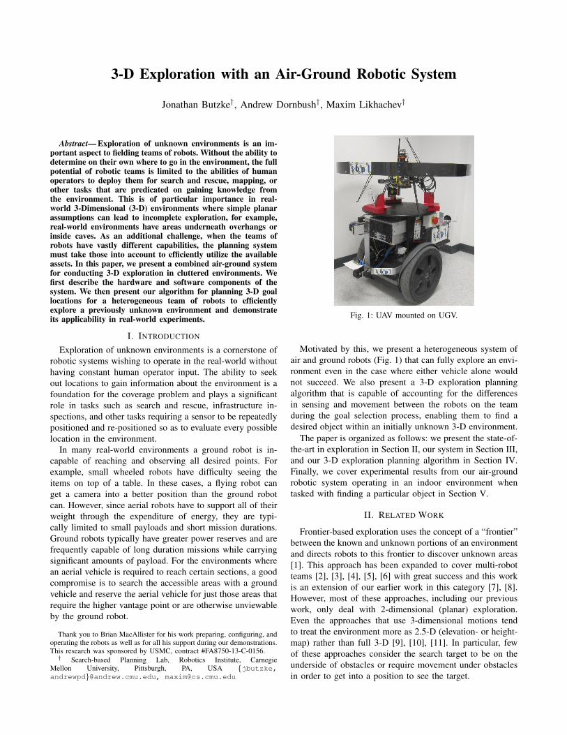
Fig. 1: UAV mounted on UGV.
Motivated by this, we present a heterogeneous system ofair and ground robots (Fig. 1) that can fully explore an envi-ronment even in the case where either vehicle alone wouldnot succeed. We also present a 3-D exploration planningalgorithm that is capable of accounting for the differencesin sensing and movement between the robots on the teamduring the goal selection process, enabling them to find adesired object within an initially unknown 3-D environment.
The paper is organized as follows: we present the state-of-the-art in exploration in Section II, our system in Section III,and our 3-D exploration planning algorithm in Section IV.Finally, we cover experimental results from our air-groundrobotic system operating in an indoor environment whentasked with finding a particular object in Section V.
II. RELATED WORK
Frontier-based exploration uses the concept of a “frontier”between the known and unknown portions of an environmentand directs robots to this frontier to discover unknown areas[1]. This approach has been expanded to cover multi-robotteams [2], [3], [4], [5], [6] with great success and this workis an extension of our earlier work in this category [7], [8].However, most of these approaches, including our previouswork, only deal with 2-dimensional (planar) exploration.Even the approaches that use 3-dimensional motions tendto treat the environment more as 2.5-D (elevation- or height-map) rather than full 3-D [9], [10], [11]. In particular, fewof these approaches consider the search target to be on theunderside of obstacles or require movement under obstaclesin order to get into a position to see the target.

One impressive approach that does consider flying underor through obstacles is the potential field/harmonic functionapproach used in [12]. Like our approach they use an octreeto represent the environment, and a camera to explore, butwhere they differ is that all of their simulated UAV’s wereidentical. It is unclear how easy it would be to incorporatea heterogeneous team of robots (including ground robots) totheir scenario. Additionally, they only consider exploration ofthe top surface of obstacles and have no method for findinga search target located on the underside of an obstacle.
There have also been numerous works relating to coop-eration between aerial and ground vehicles [13], [14], [15].Our work is based on the general principles found in these- minimize the amount of information that has to be sharedbetween platforms, maximize the amount of computing thatcan be performed in a distributed manner, and reduce theload on the operator. Our system is not fully decentralized,however; it does require a globally knowledgeable planner.While many of these only look at general collaboration be-tween air and ground robots, our approach looks specificallyat collaborative exploration of cluttered 3-D spaces.
III. AIR-GROUND ROBOTIC SYSTEM FOR 3-DEXPLORATION
We concentrate on the problem of autonomous explorationfor the purpose of finding an object of interest (OOI). Therobotic team will have minimal human input: the humanoperator will initiate the exploration, concur with launchingthe UAV, and concur with any OOI detections, but willnot provide any other direction or guidance to the robots1.Therefore, all other navigation, sensing, and decision makingmust be done on-board. To achieve this, we developed severalmodules to guide the robots through the environment asshown in Fig. 2.
UGV (Segbot):Hardware Interface
LocalizationNavigation
OOI detection
High-level Executive:Map Merger
Exploration Planner
User Interface:Web server
UAV (Hexacopter):Hardware Interface
LocalizationNavigation
OOI detection
Fig. 2: Overview of system. The Robots both have sufficientcomputing capability and sensors to move through the environmentbased on higher-level goals without further guidance.
Our system uses two primary components: a team ofrobots executing their own software for localization, navi-gation, object detection, and other local processes; and a setof high-level software modules that combine the individual
1As part of a separate line of research regarding the User Interface,we imposed the constraint that the human would have to confirm OOIdetections. Because of this, we included a decoy object in the environmentduring testing.
robot maps, select goal locations for each robot, and interfacewith the user.
The first part is our two robots: an Unmanned AerialVehicle (UAV) and an Unmanned Ground Vehicle (UGV).The UGV has a large battery capacity (sufficient for 3-4hours of operation), substantial on-board computing power,and is very stable. On the other hand, the UAV has a limitedflight time (10 minutes maximum) and computing power, butcan traverse terrain that the UGV cannot. In addition, it canmove vertically allowing it to get a better vantage point ofthe environment and “see” areas the UGV cannot. The robotsare detailed in Section III-A and their on-board software inSection III-B.
The second part of the system is the high-level moduleswhich are responsible for coordinating activities betweenthe two robots and can be executed from any availablecomputing platform. To perform their coordination function,the high-level executive has access to a map merge capabilityand the exploration planner. The map merger receives mapupdates from the two robots and forms a global map. Usingthis map, the exploration planner determines appropriategoals for each robot and provides them to the executivemodule for transmission to the robots. In addition, thehigh-level software incorporates a mechanism for providingfeedback to, and input from, the human operator. The high-level software modules are discussed in Section III-C.
A. Robot Platforms1) Melvin the Segbot: The ground vehicle component
of our system is Melvin the Segbot. Melvin is a customdesigned robot built on a Segway RMP 200 base. Attachedto this base are two computers, two 30m Hokuyo scanninglaser range finders, and a Logitech webcam (see Fig. 3a).
The computing power is split between two distinct hard-ware components. The first is the controller computer. Thismachine is responsible for the direct planning and controlof Melvin and is a 3.0GHz i5 with 8GB RAM. Thismachine handles all hardware interfaces including the motioninterface to the base. The second computer is a dual quad-core Xeon server with 16GB of RAM that executes all ofthe high level planning including the exploration planner andmap merger nodes.
(a) UGV (b) UAV
Fig. 3: Robots used for experiments. a) UGV - Large box on rightis main battery pack. Upper gray box is server, lower gray box iscontroller computer. Hokuyos and camera are mounted on structureon left. b) UAV - closeup showing bottom panning vertical Lidar,upper fixed horizontal Lidar, and forward facing camera.

2) Hexacopter: The Hexacopter serves as the aerial com-ponent of the exploration team. Like Melvin, it is equippedwith two 30m Hokuyo scanning laser range finders, a Log-itech webcam, and its own computer. The computer is an i7-2660 with 16GB of RAM that runs all of the automation on-board. The body of the Hexacopter is a modified MikrokopterHexa XL frame with custom sensor and computing mounts,power distribution electronics, and blade guards (see Fig. 3b).
B. Local Software
1) General Software & Communication: All of the com-puters run Kubuntu 12.04 with ROS Groovy. Each robothas its own instantiation of a roscore with an additionalroscore for the exploration planner and map merger, and onefor the user interface. Both of these additional roscores arephysically executed on the UGV server computing system.For the few messages that needed to be passed betweensystems, we used the ROCON software package to transferstandard ROS messages to multiple roscores. This setup wasmade to allow for movement of the high-level modules toany available computing system. By having its own roscore,all that was necessary was to update the ROCON links if weran it on a different physical machine.
2) Localization: Both robots were fully capable of inde-pendent autonomous behavior and only used the executivefor coordinating goal locations. To achieve this, each ma-chine ran its own SLAM subsystem based on the HectorSLAM package[16]. The SLAM system only maintains a 2-D map for determining the x, y, θ position and heading ofthe robot. A 2-D SLAM system was used as it providedadequate positional accuracy with significantly lower com-putational load compared to a full 3-D system. For the UAV,there was an independent system that used the verticallyoriented panning lidar to determine the ground plane. Sincethe UAV was initially mounted on top of the UGV, andduring operation it was allowed to fly over obstacles, theheight estimation system could not update the absolute heightwith every received lidar scan. On initialization, the heightestimator would analyze several scans in order to determineits initial height. Then, while flying, it would filter scanpoints that deviated more than expected from the currentestimate in order to maintain an accurate height and allowoperation over obstacles. To backup this system, there was anemergency system that would automatically reset the heightestimate if the perceived height exceeded a threshold evenif the estimate did not. Knowing that we were operatingindoors, this system ensured that we did not inadvertentlycollide with the ceiling.
3) Navigation: Each robot was responsible for its ownnavigation to the provided goal positions. We used a 3-Dstate lattice-based planner [17] running AD? to generatekinodynamically feasible trajectories for the UAV and asimple 2-D planner for the UGV. Upon receiving a goal, theon-board planner would perform a search on the local ob-stacle map to generate a trajectory from the current reportedposition (from the SLAM subsystem) to the goal state. In theevent the robot was unable to generate a feasible trajectory
(for example, if the goal was too close to an obstacle)the system would time-out and receive an updated goalfrom the exploration planner. The states used for planningare tuples consisting of a discretized translation in two orthree dimensions, and a rotation in one dimension. TheUGV planned using planar spatial coordinates and heading,〈x, y, θ〉, with 10cm cells2 and 16 discretized headings,while the UAV planned in 〈x, y, z, θ〉 with 5cm cells and16 discretized headings. The UAV was provided with auser defined “nominal height” that it would preferentiallyfly at during transits, but would deviate from as necessary.In addition, the exploration planner was provided this sameheight and would preferentially select goal locations at thisaltitude. This setup allowed the planner to construct full 3-D trajectories going over, below, or around obstacles whilemaintaining a preferred height for the UAV to operate at.
Once the robot had a feasible trajectory, it would use thelocal controller to generate motor inputs to follow the trajec-tory. For the UGV this was performed using a trajectory roll-out scheme that estimated different motions based on a smallfinite set of short-time horizon control inputs and selectedthe input that provided an endpoint closest in position andorientation to the desired trajectory. The UAV controller useda PID control for position to generate its control inputs basedon the measured error between its current location and thenext way-point along the desired trajectory. Altitude and yawwere handled by separate PID controllers in a similar fashion.
4) Object Detection: Besides the motion control subsys-tems, each robot performed its own analysis of the videofeed in an effort to detect the OOI. This subsystem wasbased around an existing vision detection system CMVision[18]. This system was trained to detect a specific coloredobject; for our experiments it was a green tablet case. Likemany other color based object detection systems, recalibra-tion was required for different lighting conditions. Color-only detection was selected in order to keep the processingrequirements minimized. Even so, this sub-system requiredthe largest percentage of computing power used. When arobot detects a possible OOI, it will transmit a still imageto the user (Fig. 4, right image - OOI is bottom center),pause exploration, and hold position until it receives eitherconfirmation or rejection of the reported OOI.
C. High-Level Software
1) High Level Executive: The high-level executive isresponsible for coordinating the robots. As part of thisfunction, it provides the interface between the map merger /exploration planner module, the user interface module, andthe robots.
2) User Interface: The human user only has a a fewinputs to the system during run-time. The two chief inputsfrom the user are to start and concur with the completion ofexploration. The only other input is concurrence on launchingthe UAV which is included for safety considerations. All
2In this text, we use the term “cell” to refer to 3-dimensional discretizedlocations defined by a center-point, 〈x, y, z〉. We use the term “state” torefer to a 3- or 4-dimensional discretized pose, 〈x, y, (z), θ〉.
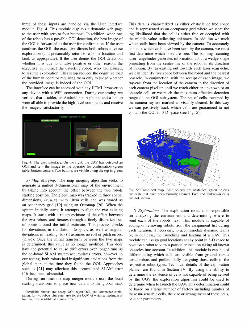
three of these inputs are handled via the User Interfacemodule, Fig. 4. This module displays a dynamic web pageto the user with zero to four buttons3. In addition, when oneof the robots has a possible OOI detection, the best image ofthe OOI is forwarded to the user for confirmation. If the userconfirms the OOI, the executive directs both robots to ceaseexploration (and presumably return to a home location andland, as appropriate). If the user denies the OOI detection,whether it is due to a false positive or other reason, theexecutive will direct the detecting robot, who had paused,to resume exploration. This setup reduces the cognitive loadof the human operator requiring them only to judge whetherthe provided image is indeed of the OOI.
The interface can be accessed with any HTML browser onany device with a WiFi connection. During our testing weverified that a tablet, an Android smart-phone, and a laptopwere all able to provide the high-level commands and receivethe images, satisfactorily.
Fig. 4: The user interface. On the right, the UAV has detected anOOI and sent the image to the operator for confirmation (greentablet bottom center). Two buttons are visible along the top in green.
3) Map Merging: The map merging algorithm seeks togenerate a unified 3-dimensional map of the environmentby taking into account the offset between the two robotsstarting position. The global map was tracked in three spatialdimensions, 〈x, y, z〉, with 10cm cells and was stored asan occupancy grid [19] using an Octomap [20]. When thesystem initially starts, it attempts to align the two existingmaps. It starts with a rough estimate of the offset betweenthe two robots, and iterates through a finely discretized setof points around the initial estimate. This process checksfor deviations in translation, 〈x, y, z〉, as well as angulardeviations in heading, 〈θ〉 (it assumes no roll or pitch errors,〈φ, ψ〉). Once the initial transform between the two mapsis determined, this value is no longer modified. This doeshave the potential to cause drift errors over longer runs asthe on-board SLAM system accumulates errors, however, inour testing, both robots had insignificant deviations from theglobal map at the time they found the OOI. Approachessuch as [21] may alleviate this accumulated SLAM errorif it becomes substantial.
During run-time, the map merger module uses the fixedstarting transform to place new data into the global map.
3Available buttons are: accept OOI, reject OOI, and commence explo-ration, for two robots plus enter area for the UGV, of which a maximum offour are ever available at a given time.
This data is characterized as either obstacle or free spaceand is represented as an occupancy grid where we store thelog likelihood that the cell is either free or occupied withthe middle value indicating unknown. In addition we trackwhich cells have been viewed by the camera. To accuratelyannotate which cells have been seen by the camera, we mustfirst determine which ones are free. The panning scanninglaser rangefinder generates information about a wedge shapeprojecting from the center-line of the robot in its directionof motion. By ray-casting out towards each laser scan echo,we can identify free space between the robot and the nearestobstacle. In conjunction, with the receipt of each image, weray-cast from the location of the camera in the direction ofeach camera pixel up until we reach either an unknown or anobstacle cell, or we reach the maximum effective detectionrange of the OOI subsystem. The set of cells traversed bythe camera ray are marked as visually cleared. In this waywe can positively track which cells are guaranteed to notcontain the OOI in 3-D space (see Fig. 5).
Fig. 5: Combined map. Blue objects are obstacles, green objectsare cells that have been visually cleared. Free and Unknown cellsare not shown.
4) Exploration: The exploration module is responsiblefor analyzing the environment and determining where tosend each of the robots next. This module is capable ofadding or removing robots from the assignment list duringeach iteration, if necessary, to accommodate dynamic teamsor, in our case, the launching and landing of a UAV. Thismodule can assign goal locations at any point in 3-D space toposition a robot to view a particular location taking all knownobstacles into account. In addition, this module is capable ofdifferentiating which cells are visible from ground versusaerial robots and preferentially assigning those cells to therespective robot types. Technical details of the explorationplanner are found in Section IV. By using the ability todetermine the existence of cells not capable of being sensedby the UGV the exploration algorithm could be used todetermine when to launch the UAV. This determination couldbe based on a large number of factors including number ofthese un-sensable cells, the size or arrangement of these cells,or other parameters.
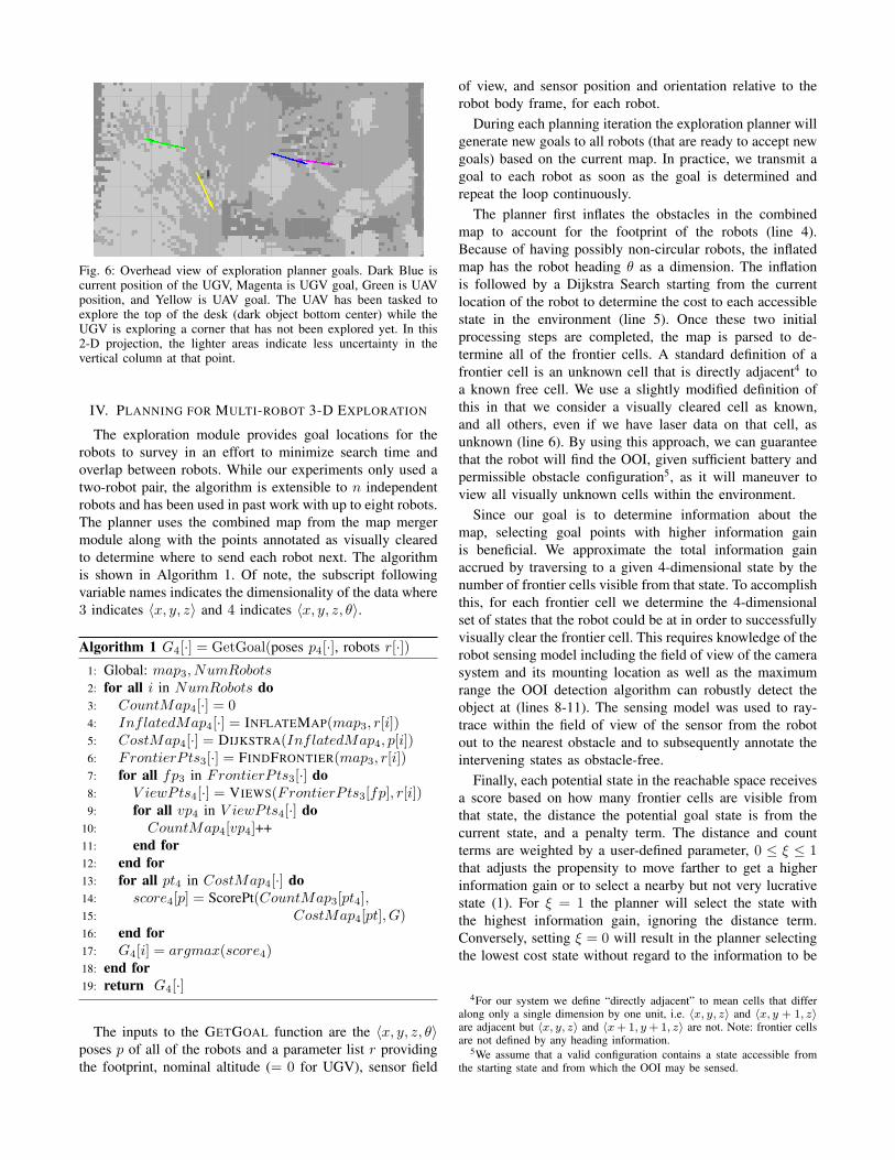
Fig. 6: Overhead view of exploration planner goals. Dark Blue iscurrent position of the UGV, Magenta is UGV goal, Green is UAVposition, and Yellow is UAV goal. The UAV has been tasked toexplore the top of the desk (dark object bottom center) while theUGV is exploring a corner that has not been explored yet. In this2-D projection, the lighter areas indicate less uncertainty in thevertical column at that point.
IV. PLANNING FOR MULTI-ROBOT 3-D EXPLORATION
The exploration module provides goal locations for therobots to survey in an effort to minimize search time andoverlap between robots. While our experiments only used atwo-robot pair, the algorithm is extensible to n independentrobots and has been used in past work with up to eight robots.The planner uses the combined map from the map mergermodule along with the points annotated as visually clearedto determine where to send each robot next. The algorithmis shown in Algorithm 1. Of note, the subscript followingvariable names indicates the dimensionality of the data where3 indicates 〈x, y, z〉 and 4 indicates 〈x, y, z, θ〉.
Algorithm 1 G4[·] = GetGoal(poses p4[·], robots r[·])1: Global: map3, NumRobots2: for all i in NumRobots do3: CountMap4[·] = 04: InflatedMap4[·] = INFLATEMAP(map3, r[i])5: CostMap4[·] = DIJKSTRA(InflatedMap4, p[i])6: FrontierP ts3[·] = FINDFRONTIER(map3, r[i])7: for all fp3 in FrontierP ts3[·] do8: V iewPts4[·] = VIEWS(FrontierP ts3[fp], r[i])9: for all vp4 in V iewPts4[·] do
10: CountMap4[vp4]++11: end for12: end for13: for all pt4 in CostMap4[·] do14: score4[p] = ScorePt(CountMap3[pt4],15: CostMap4[pt], G)16: end for17: G4[i] = argmax(score4)18: end for19: return G4[·]
The inputs to the GETGOAL function are the 〈x, y, z, θ〉poses p of all of the robots and a parameter list r providingthe footprint, nominal altitude (= 0 for UGV), sensor field
of view, and sensor position and orientation relative to therobot body frame, for each robot.
During each planning iteration the exploration planner willgenerate new goals to all robots (that are ready to accept newgoals) based on the current map. In practice, we transmit agoal to each robot as soon as the goal is determined andrepeat the loop continuously.
The planner first inflates the obstacles in the combinedmap to account for the footprint of the robots (line 4).Because of having possibly non-circular robots, the inflatedmap has the robot heading θ as a dimension. The inflationis followed by a Dijkstra Search starting from the currentlocation of the robot to determine the cost to each accessiblestate in the environment (line 5). Once these two initialprocessing steps are completed, the map is parsed to de-termine all of the frontier cells. A standard definition of afrontier cell is an unknown cell that is directly adjacent4 toa known free cell. We use a slightly modified definition ofthis in that we consider a visually cleared cell as known,and all others, even if we have laser data on that cell, asunknown (line 6). By using this approach, we can guaranteethat the robot will find the OOI, given sufficient battery andpermissible obstacle configuration5, as it will maneuver toview all visually unknown cells within the environment.
Since our goal is to determine information about themap, selecting goal points with higher information gainis beneficial. We approximate the total information gainaccrued by traversing to a given 4-dimensional state by thenumber of frontier cells visible from that state. To accomplishthis, for each frontier cell we determine the 4-dimensionalset of states that the robot could be at in order to successfullyvisually clear the frontier cell. This requires knowledge of therobot sensing model including the field of view of the camerasystem and its mounting location as well as the maximumrange the OOI detection algorithm can robustly detect theobject at (lines 8-11). The sensing model was used to ray-trace within the field of view of the sensor from the robotout to the nearest obstacle and to subsequently annotate theintervening states as obstacle-free.
Finally, each potential state in the reachable space receivesa score based on how many frontier cells are visible fromthat state, the distance the potential goal state is from thecurrent state, and a penalty term. The distance and countterms are weighted by a user-defined parameter, 0 ≤ ξ ≤ 1that adjusts the propensity to move farther to get a higherinformation gain or to select a nearby but not very lucrativestate (1). For ξ = 1 the planner will select the state withthe highest information gain, ignoring the distance term.Conversely, setting ξ = 0 will result in the planner selectingthe lowest cost state without regard to the information to be
4For our system we define “directly adjacent” to mean cells that differalong only a single dimension by one unit, i.e. 〈x, y, z〉 and 〈x, y + 1, z〉are adjacent but 〈x, y, z〉 and 〈x+1, y+1, z〉 are not. Note: frontier cellsare not defined by any heading information.
5We assume that a valid configuration contains a state accessible fromthe starting state and from which the OOI may be sensed.

gained.
score[i] =count[i]ξ
cost[i](1−ξ)· penalty[i] (1)
The penalty term can incorporate a wide range of userpreferred behavior. For our system, this term was constructedto downgrade states that are in close proximity to any otherrobots goal state. In addition, this term also penalized veryshort range motions that are harder to execute (2). ThethresholdL and thresholdD values are set by the user6.
penalty[i] = LENGTH(i) · minj,i6=j
(PROXIMITY
(i, G(j)
))(2)
LENGTH(a) =
{1 COSTMAP(a) ≥ thresholdLCOSTMAP(a)
thresholdLotherwise
PROXIMITY(a, b) =
{1 dist(a, b) ≥ thresholdD
dist(a,b)thresholdD
otherwise
Due to the UAV’s limited flight time, we provide afurther enhancement to maximize the UAV’s value. Whendetermining the frontier points on line 6, the explorationplanner first considers only those points that are not visibleto the UGV. In this way, the planner will first send the UAVto cover portions of the environment the UGV cannot sense.Once it has exhausted the UAV-only points without findingany candidates, it will reevaluate based on all frontier points7.
In order to determine which states are or are not visible tothe UGV, we ray-cast from the potential target state to theset of states that the UGV sensor could be located in (takinginto account orientation and obstacles). If all rays encounterobstacles then the state is not visible. In all other cases thereexists at least one viable configuration of the UGV that willallow the target state to be sensed.
V. EXPERIMENTS
A. Setup
Our experiments aimed to validate our entire approach toexploration by having the robot team search a previouslyunknown area attempting to locate a particular tablet (ourOOI) identified by its unique color. The operator stoodoutside the area and issued the allowed commands with noother interaction with the robots. We defined a successfulrun if either of the robots were able to identify the tabletbefore the UAV depleted its battery. Depending on the lengthof time spent airborne, and to a lesser extent the amountof processing load and time spent operating while mountedto the UGV, the UAV is limited to between four and ten
6The Length thresholdL duplicates to some extent the ξ parameter. Thedifference being that thresholdL is an absolute value - the penalty is appliedindependent of the information gain - while the ξ parameter only changesthe relative importance of cost vs. information gain.
7This process may transition multiple times between UAV-only and allfrontier points as the environment is explored and new obstacles discovered.
minutes of flight, compared to several hours of explorationtime for the UGV. An unsuccessful run was one in whichafter conducting a search the robots were not able to find thetablet before a low battery forced the UAV to land8.
We conducted our experiments in an enclosed indoor areameasuring approximately 30m × 10m × 5m of which theupper 2-3m were occupied with pipes and conduit. The areawas partitioned into sections with movable walls and objectssuch as a desk and filing cabinet were placed inside the area.This resulted in approximately 400,000 cells capable of beingdetected and analyzed, depending on obstacle placementand room configuration. The robots started from the samelocation for all tests near the edge of the search area andhad a predetermined first goal located 5m into the explorationzone that the UGV moved to when commanded to “enter thearea”.
We had different people place the OOI during our ex-periments to rule out any bias in selecting locations thatwere particularly easy or hard for the system. The directionprovided to the person placing the OOI was to place it sothat the OOI would only be visible to the UAV once it wasairborne. This was done by placing the OOI in a location notvisible from the UAV prior to it taking off from the UGVand not visible to the UGV. Separate tests were performedto verify the UGV was capable of also detecting the OOI,and it was successful on all runs.
The test environment had one object that had an identicalcolor as the OOI and served as a decoy for the detectionsystem by causing a false positive. In the event the decoy wasdetected, the operator rejected the classification and resumedthe exploration. Decoy detection was not deemed to be afailure but the time spent pausing and waiting for the operatorto reject the OOI was counted towards the completion time.
Since the exploration algorithm has several user selectableparameters, we set them as follows: To achieve balancebetween distance traveled and information gain, we setξ = 0.5, to facilitate the robots spreading out, we setthresholdD = 5, and to discourage very short range goals,we set thresholdL = 1.2 for all runs. In addition, while themap merger process can determine when to launch the UAVbased on detecting unreachable frontier states, for all of thetest runs, we had the UAV launch at the first opportunity after2 minutes 30 seconds of UGV only exploration9. The 2:30takeoff time was based on prior experiments that indicateda reasonable percentage of the UGV accessible space wasexplored by that point on average (for an example, seeFig. 7b for the case where the UAV took off late - the UGVexploration progress plateaus at approximately 2:30).
The cameras used on both robots were identical LogitechC310 webcams that provided images at 1280 × 720 pixels at25Hz. The UGV camera was mounted approximately 20cm
8The action was automatic and occurred when battery voltage underload averaged less than 13.8V for 10 seconds. Runs terminated due to amechanical failure of a robot were not counted in the results.
9There was one area of the environment that the overhead obstacles weretoo low to allow for the UAV to launch which caused the takeoff to bedelayed on two occasions - once by 10 seconds (run 5) and once by 2:25(run 1).
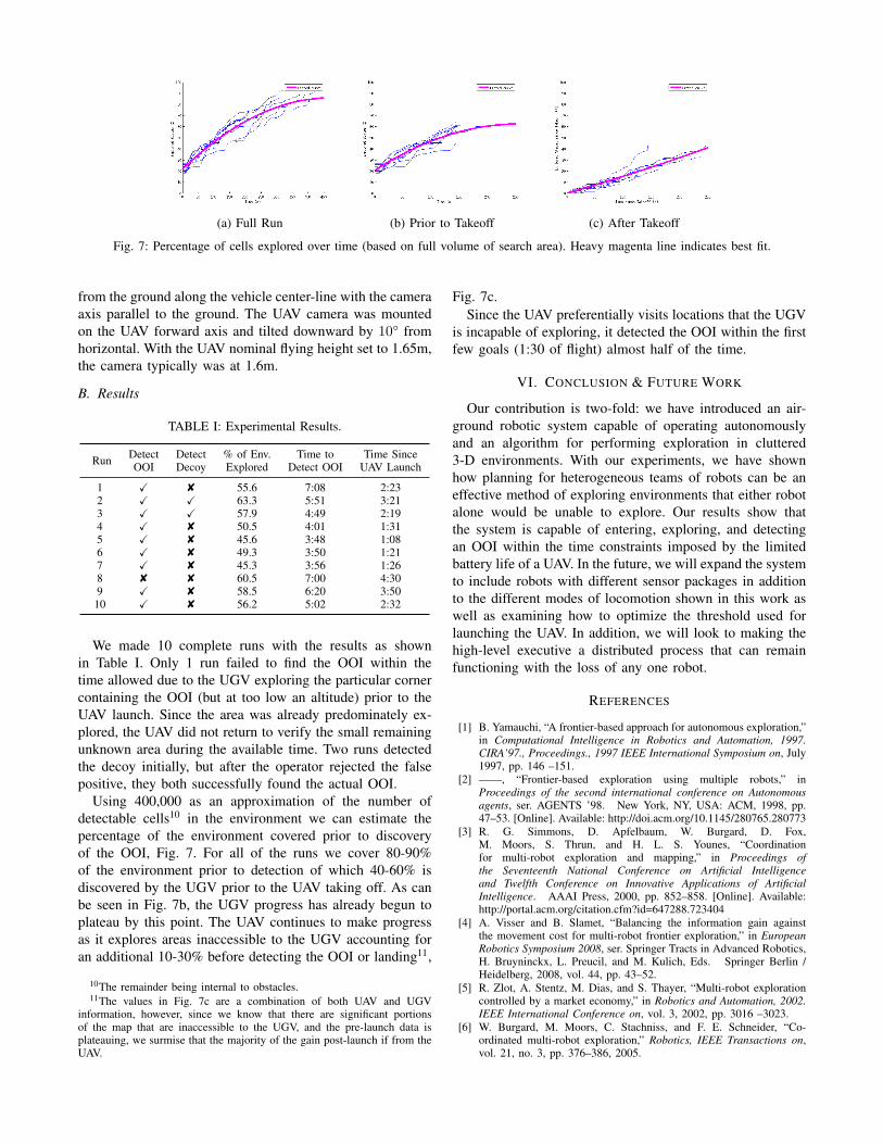
(a) Full Run (b) Prior to Takeoff (c) After Takeoff
Fig. 7: Percentage of cells explored over time (based on full volume of search area). Heavy magenta line indicates best fit.
from the ground along the vehicle center-line with the cameraaxis parallel to the ground. The UAV camera was mountedon the UAV forward axis and tilted downward by 10° fromhorizontal. With the UAV nominal flying height set to 1.65m,the camera typically was at 1.6m.
B. Results
TABLE I: Experimental Results.
Run Detect Detect % of Env. Time to Time SinceOOI Decoy Explored Detect OOI UAV Launch
1 X 8 55.6 7:08 2:232 X X 63.3 5:51 3:213 X X 57.9 4:49 2:194 X 8 50.5 4:01 1:315 X 8 45.6 3:48 1:086 X 8 49.3 3:50 1:217 X 8 45.3 3:56 1:268 8 8 60.5 7:00 4:309 X 8 58.5 6:20 3:5010 X 8 56.2 5:02 2:32
We made 10 complete runs with the results as shownin Table I. Only 1 run failed to find the OOI within thetime allowed due to the UGV exploring the particular cornercontaining the OOI (but at too low an altitude) prior to theUAV launch. Since the area was already predominately ex-plored, the UAV did not return to verify the small remainingunknown area during the available time. Two runs detectedthe decoy initially, but after the operator rejected the falsepositive, they both successfully found the actual OOI.
Using 400,000 as an approximation of the number ofdetectable cells10 in the environment we can estimate thepercentage of the environment covered prior to discoveryof the OOI, Fig. 7. For all of the runs we cover 80-90%of the environment prior to detection of which 40-60% isdiscovered by the UGV prior to the UAV taking off. As canbe seen in Fig. 7b, the UGV progress has already begun toplateau by this point. The UAV continues to make progressas it explores areas inaccessible to the UGV accounting foran additional 10-30% before detecting the OOI or landing11,
10The remainder being internal to obstacles.11The values in Fig. 7c are a combination of both UAV and UGV
information, however, since we know that there are significant portionsof the map that are inaccessible to the UGV, and the pre-launch data isplateauing, we surmise that the majority of the gain post-launch if from theUAV.
Fig. 7c.Since the UAV preferentially visits locations that the UGV
is incapable of exploring, it detected the OOI within the firstfew goals (1:30 of flight) almost half of the time.
VI. CONCLUSION & FUTURE WORK
Our contribution is two-fold: we have introduced an air-ground robotic system capable of operating autonomouslyand an algorithm for performing exploration in cluttered3-D environments. With our experiments, we have shownhow planning for heterogeneous teams of robots can be aneffective method of exploring environments that either robotalone would be unable to explore. Our results show thatthe system is capable of entering, exploring, and detectingan OOI within the time constraints imposed by the limitedbattery life of a UAV. In the future, we will expand the systemto include robots with different sensor packages in additionto the different modes of locomotion shown in this work aswell as examining how to optimize the threshold used forlaunching the UAV. In addition, we will look to making thehigh-level executive a distributed process that can remainfunctioning with the loss of any one robot.
REFERENCES
[1] B. Yamauchi, “A frontier-based approach for autonomous exploration,”in Computational Intelligence in Robotics and Automation, 1997.CIRA’97., Proceedings., 1997 IEEE International Symposium on, July1997, pp. 146 –151.
[2] ——, “Frontier-based exploration using multiple robots,” inProceedings of the second international conference on Autonomousagents, ser. AGENTS ’98. New York, NY, USA: ACM, 1998, pp.47–53. [Online]. Available: http://doi.acm.org/10.1145/280765.280773
[3] R. G. Simmons, D. Apfelbaum, W. Burgard, D. Fox,M. Moors, S. Thrun, and H. L. S. Younes, “Coordinationfor multi-robot exploration and mapping,” in Proceedings ofthe Seventeenth National Conference on Artificial Intelligenceand Twelfth Conference on Innovative Applications of ArtificialIntelligence. AAAI Press, 2000, pp. 852–858. [Online]. Available:http://portal.acm.org/citation.cfm?id=647288.723404
[4] A. Visser and B. Slamet, “Balancing the information gain againstthe movement cost for multi-robot frontier exploration,” in EuropeanRobotics Symposium 2008, ser. Springer Tracts in Advanced Robotics,H. Bruyninckx, L. Preucil, and M. Kulich, Eds. Springer Berlin /Heidelberg, 2008, vol. 44, pp. 43–52.
[5] R. Zlot, A. Stentz, M. Dias, and S. Thayer, “Multi-robot explorationcontrolled by a market economy,” in Robotics and Automation, 2002.IEEE International Conference on, vol. 3, 2002, pp. 3016 –3023.
[6] W. Burgard, M. Moors, C. Stachniss, and F. E. Schneider, “Co-ordinated multi-robot exploration,” Robotics, IEEE Transactions on,vol. 21, no. 3, pp. 376–386, 2005.

[7] J. Butzke, K. Daniilidis, A. Kushleyev, D. D. Lee, M. Likhachev,C. Phillips, and M. Phillips, “The university of pennsylvaniamagic 2010 multi-robot unmanned vehicle system,” Journal of FieldRobotics, vol. 29, no. 5, pp. 745–761, 2012. [Online]. Available:http://dx.doi.org/10.1002/rob.21437
[8] J. Butzke and M. Likhachev, “Planning for multi-robot explorationwith multiple objective utility functions,” in Intelligent Robots andSystems (IROS), 2011 IEEE/RSJ International Conference on. IEEE,2011, pp. 3254–3259.
[9] P. Sujit and R. Beard, “Multiple uav exploration of an unknownregion,” Annals of Mathematics and Artificial Intelligence,vol. 52, no. 2-4, pp. 335–366, 2008. [Online]. Available:http://dx.doi.org/10.1007/s10472-009-9128-7
[10] R. Sawhney, K. M. Krishna, and K. Srinathan, “On fastexploration in 2d and 3d terrains with multiple robots,” inProceedings of The 8th International Conference on AutonomousAgents and Multiagent Systems - Volume 1, ser. AAMAS ’09.Richland, SC: International Foundation for Autonomous Agentsand Multiagent Systems, 2009, pp. 73–80. [Online]. Available:http://dl.acm.org/citation.cfm?id=1558013.1558022
[11] K. Yang, S. Keat Gan, and S. Sukkarieh, “A gaussian process-based rrtplanner for the exploration of an unknown and cluttered environmentwith a uav,” Advanced Robotics, vol. 27, no. 6, pp. 431–443, 2013.[Online]. Available: http://dx.doi.org/10.1080/01691864.2013.756386
[12] C. Rasche, C. Stern, L. Kleinjohann, and B. Kleinjohann, “A dis-tributed multi-uav path planning approach for 3d environments,” inAutomation, Robotics and Applications (ICARA), 2011 5th Interna-tional Conference on, Dec 2011, pp. 7–12.
[13] R. Vidal, O. Shakernia, H. J. Kim, D. H. Shim, and S. Sastry,“Probabilistic pursuit-evasion games: theory, implementation, and ex-perimental evaluation,” Robotics and Automation, IEEE Transactionson, vol. 18, no. 5, pp. 662–669, 2002.
[14] H. Tanner, “Switched uav-ugv cooperation scheme for target detec-tion,” in Robotics and Automation, 2007 IEEE International Confer-ence on, April 2007, pp. 3457–3462.
[15] B. Grocholsky, J. Keller, V. Kumar, and G. Pappas, “Cooperativeair and ground surveillance,” Robotics Automation Magazine, IEEE,vol. 13, no. 3, pp. 16–25, Sept 2006.
[16] S. Kohlbrecher, J. Meyer, T. Graber, K. Petersen, U. Klingauf, andO. von Stryk, “Hector open source modules for autonomous mappingand navigation with rescue robots,” in RoboCup 2013: Robot WorldCup XVII. Springer, 2014, pp. 624–631.
[17] B. MacAllister, J. Butzke, A. Kushleyev, H. Pandey, and M. Likhachev,“Path planning for non-circular micro aerial vehicles in constrainedenvironments,” in Robotics and Automation (ICRA), 2013 IEEE Inter-national Conference on. IEEE, 2013, pp. 3933–3940.
[18] J. Bruce, T. Balch, and M. Veloso, “Fast and inexpensive color imagesegmentation for interactive robots,” in Intelligent Robots and Sys-tems, 2000. (IROS 2000). Proceedings. 2000 IEEE/RSJ InternationalConference on, vol. 3, 2000, pp. 2061–2066 vol.3.
[19] A. Elfes, “Sonar-based real-world mapping and navigation,” Roboticsand Automation, IEEE Journal of, vol. 3, no. 3, pp. 249–265, June1987.
[20] A. Hornung, K. Wurm, M. Bennewitz, C. Stachniss, and W. Burgard,“Octomap: an efficient probabilistic 3d mapping framework basedon octrees,” Autonomous Robots, vol. 34, no. 3, pp. 189–206, 2013.[Online]. Available: http://dx.doi.org/10.1007/s10514-012-9321-0
[21] J. Jessup, S. Givigi, and A. Beaulieu, “Robust and efficient multi-robot 3d mapping with octree based occupancy grids,” in Systems,Man and Cybernetics (SMC), 2014 IEEE International Conferenceon, Oct 2014, pp. 3996–4001.