3” chipper/shredder - tractorsupply.com · nut, 2 plcs figure 6 shredder safety guard shredder...
TRANSCRIPT
3” Chipper/Shredder
This safety alert symbol identifies important safety messages in this manual. Failure to follow this important safety information may result in serious injury or death.
MODEL # 108240
Operation Manual
!Part # 108241 Rev A

1100 W 120th Ave, Suite 600Westminster, CO 80234 • 720-287-5182
For Service or QuestionsCall 1-877-487-8275720-287-5182
www.dirtyhandtools.comDirty Hand Tools® is a brand of

Table of Contents
Important Safety Information Intended Use ..............................................................................4 Personal Protective Equipment ..................................................4 General Safety ............................................................................5 Safety Decals ..............................................................................6 Assembly Instructions Deploying the Stand ....................................................................7 Attaching the Wheels..................................................................7 Attaching the Inlet Tube .............................................................7 Attaching the Hopper Guard ......................................................7 Attaching the Debris Collection Bag ..........................................8Chipper/Shredder Overview ........................................................9Operating Precautions ................................................................10 Operation Preparation ................................................................................11 Pre-start Inspection ...................................................................12 Startup .......................................................................................13 Shutting Down ..........................................................................13 Operation Recommendations ....................................................14Maintenance Maintenance Schedule ..............................................................15 Shredding Hammer Rotation and Replacement .......................18 Chipping Knives Sharpening and Replacement ........................19Assembly and Parts Lists Chipper/Shredder Assembly .....................................................20 Chipper/Shredder Assembly Parts List .....................................21 Engine and Housing Assembly .................................................22 Engine and Housing Assembly Parts list ..................................23 Chipper Rotor Assembly ...........................................................24 Chipper Rotor Assembly Parts List ..........................................25Troubleshooting ..........................................................................26Storage .........................................................................................27Warranty & Specifications .........................................Back Cover
3
Important Safety Information
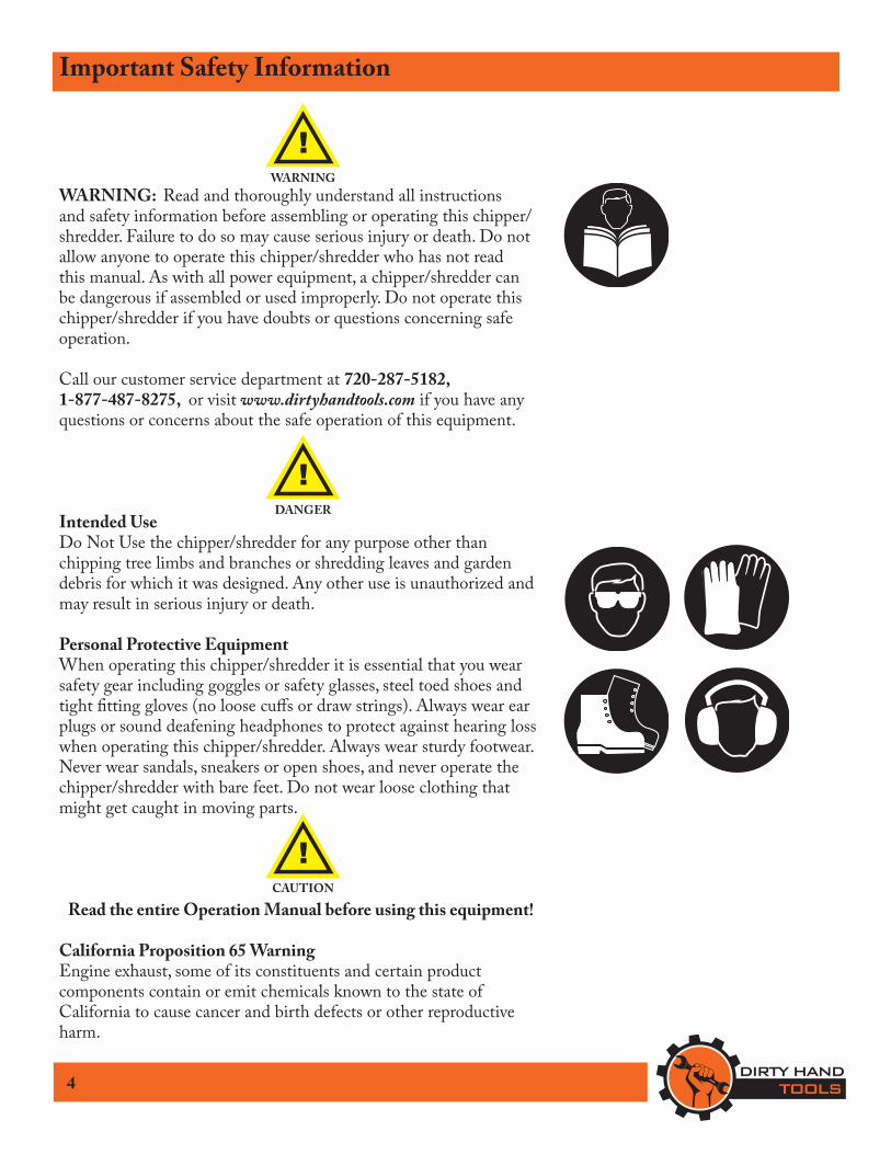
WARNING: Read and thoroughly understand all instructions and safety information before assembling or operating this chipper/shredder. Failure to do so may cause serious injury or death. Do not allow anyone to operate this chipper/shredder who has not read this manual. As with all power equipment, a chipper/shredder can be dangerous if assembled or used improperly. Do not operate this chipper/shredder if you have doubts or questions concerning safe operation.
Call our customer service department at 720-287-5182, 1-877-487-8275, or visit www.dirtyhandtools.com if you have any questions or concerns about the safe operation of this equipment.
Intended UseDo Not Use the chipper/shredder for any purpose other than chipping tree limbs and branches or shredding leaves and garden debris for which it was designed. Any other use is unauthorized and may result in serious injury or death.
Personal Protective EquipmentWhen operating this chipper/shredder it is essential that you wear safety gear including goggles or safety glasses, steel toed shoes and tight fitting gloves (no loose cuffs or draw strings). Always wear ear plugs or sound deafening headphones to protect against hearing loss when operating this chipper/shredder. Always wear sturdy footwear. Never wear sandals, sneakers or open shoes, and never operate the chipper/shredder with bare feet. Do not wear loose clothing that might get caught in moving parts.
Read the entire Operation Manual before using this equipment!
California Proposition 65 WarningEngine exhaust, some of its constituents and certain product components contain or emit chemicals known to the state of California to cause cancer and birth defects or other reproductive harm.
4
!WARNING
!DANGER
!CAUTION
5
Important Safety InformationGeneral SafetyFailure to follow warnings, cautions, assembly and operation instructions in the Operation Manual may result in serious injury or death.
READ THE OPERATION MANUAL BEFORE USESINGLE PERSON OPERATION ONLY!
THIS UNIT MEETS OR EXCEEDSANSI B71-6-2000 SAFETY STANDARDS
• Do not permit children to operate this equipment at any time. Do not permit others that have not read and understood the complete Operation Manual to operate this equipment.
• Keep all people and pets a minimum of 10 feet away from the work area when operating this chipper/shredder.
• Do not operate the chipper/shredder when under the influence of alcohol, drugs or medication.
• Do not allow a person who is tired or otherwise impaired or not completely alert to operate the chipper/shredder.
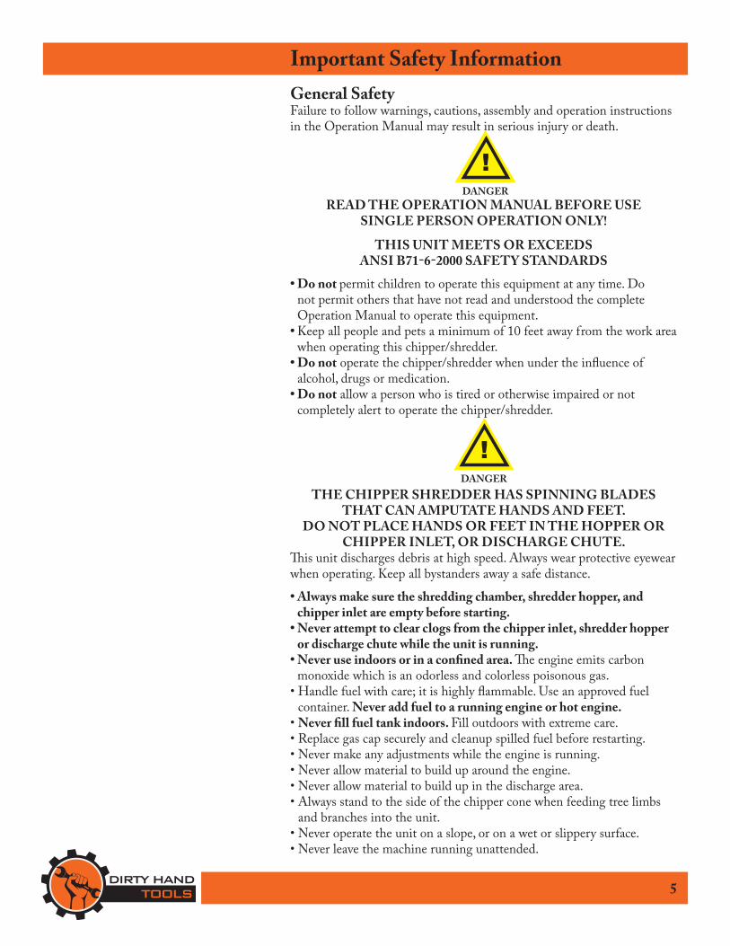
THE CHIPPER SHREDDER HAS SPINNING BLADESTHAT CAN AMPUTATE HANDS AND FEET.
DO NOT PLACE HANDS OR FEET IN THE HOPPER OR CHIPPER INLET, OR DISCHARGE CHUTE.
This unit discharges debris at high speed. Always wear protective eyewear when operating. Keep all bystanders away a safe distance.
• Always make sure the shredding chamber, shredder hopper, and chipper inlet are empty before starting.
• Never attempt to clear clogs from the chipper inlet, shredder hopper or discharge chute while the unit is running.
• Never use indoors or in a confined area. The engine emits carbon monoxide which is an odorless and colorless poisonous gas.
• Handle fuel with care; it is highly flammable. Use an approved fuel container. Never add fuel to a running engine or hot engine.
• Never fill fuel tank indoors. Fill outdoors with extreme care. • Replace gas cap securely and cleanup spilled fuel before restarting.• Never make any adjustments while the engine is running.• Never allow material to build up around the engine.• Never allow material to build up in the discharge area.• Always stand to the side of the chipper cone when feeding tree limbs
and branches into the unit.• Never operate the unit on a slope, or on a wet or slippery surface.• Never leave the machine running unattended.
!DANGER
!DANGER
Important Safety Information
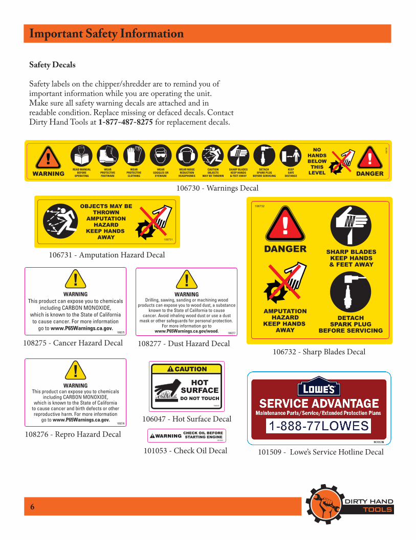
Safety Decals
Safety labels on the chipper/shredder are to remind you of important information while you are operating the unit. Make sure all safety warning decals are attached and in readable condition. Replace missing or defaced decals. Contact Dirty Hand Tools at 1-877-487-8275 for replacement decals.
6
WEARPROTECTIVEFOOTWARE
WEARPROTECTIVECLOTHING
WEARGOGGLES OR
EYEWARE
WEAR NOISEREDUCTION
HEADPHONES
CAUTIONOBJECTS
MAY BE THROWN
SHARP BLADESKEEP HANDS& FEET AWAY
DETACH SPARK PLUG
BEFORE SERVICING
READ MANUALBEFORE
OPERATINGWARNINGKEEPSAFE
DISTANCE
NOHANDSBELOWTHIS
LEVEL DANGER
1067
30
106730 - Warnings Decal
DANGER
AMPUTATIONHAZARD
KEEP HANDS AWAY
DETACHSPARK PLUG
BEFORE SERVICING
106732
SHARP BLADESKEEP HANDS& FEET AWAY
106732 - Sharp Blades Decal
OBJECTS MAY BETHROWN
AMPUTATIONHAZARD
KEEP HANDS AWAY 106731
106731 - Amputation Hazard Decal
106047
HOTSURFACEDO NOT TOUCH
CAUTION
106047 - Hot Surface DecalCHECK OIL BEFORE STARTING ENGINE
101053
101053 - Check Oil Decal 101509 - Lowe’s Service Hotline Decal
WARNINGThis product can expose you to chemicals
including CARBON MONOXIDE,which is known to the State of Californiato cause cancer. For more information
go to www.P65Warnings.ca.gov.
!
108275
108275 - Cancer Hazard Decal
WARNINGThis product can expose you to chemicals
including CARBON MONOXIDE,which is known to the State of California
to cause cancer and birth defects or otherreproductive harm. For more information
go to www.P65Warnings.ca.gov.
!
108276
108276 - Repro Hazard Decal
WARNINGDrilling, sawing, sanding or machining wood
products can expose you to wood dust, a substanceknown to the State of California to cause
cancer. Avoid inhaling wood dust or use a dustmask or other safeguards for personal protection.
For more information go towww.P65Warnings.ca.gov/wood.
!
108277
108277 - Dust Hazard Decal
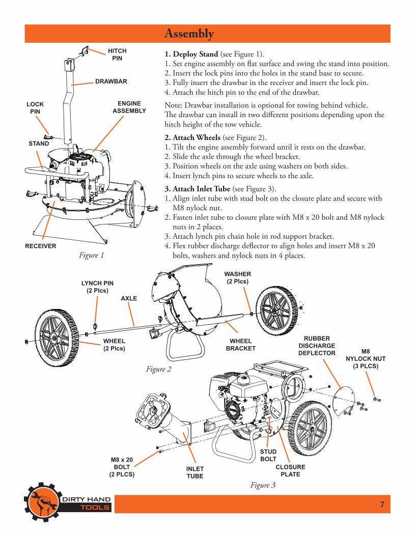
Assembly1. Deploy Stand (see Figure 1).1. Set engine assembly on flat surface and swing the stand into position. 2. Insert the lock pins into the holes in the stand base to secure.3. Fully insert the drawbar in the receiver and insert the lock pin.4. Attach the hitch pin to the end of the drawbar.Note: Drawbar installation is optional for towing behind vehicle.The drawbar can install in two different positions depending upon the hitch height of the tow vehicle.
2. Attach Wheels (see Figure 2).1. Tilt the engine assembly forward until it rests on the drawbar.2. Slide the axle through the wheel bracket.3. Position wheels on the axle using washers on both sides.4. Insert lynch pins to secure wheels to the axle.
3. Attach Inlet Tube (see Figure 3).1. Align inlet tube with stud bolt on the closure plate and secure with
M8 nylock nut.2. Fasten inlet tube to closure plate with M8 x 20 bolt and M8 nylock
nuts in 2 places.3. Attach lynch pin chain hole in rod support bracket.4. Flex rubber discharge deflector to align holes and insert M8 x 20
bolts, washers and nylock nuts in 4 places.
7
Figure 1
ENGINE ASSEMBLY
STAND
RECEIVER
HITCH PIN
DRAWBAR
LOCK PIN
Figure 2
LYNCH PIN(2 Plcs)
AXLE
WASHER(2 Plcs)
WHEELBRACKET
WHEEL(2 Plcs)
INLETTUBE
STUDBOLTM8 x 20
BOLT(2 PLCS)
M8NYLOCK NUT
(3 PLCS)
CLOSURE PLATE
Figure 3
RUBBERDISCHARGEDEFLECTOR
8
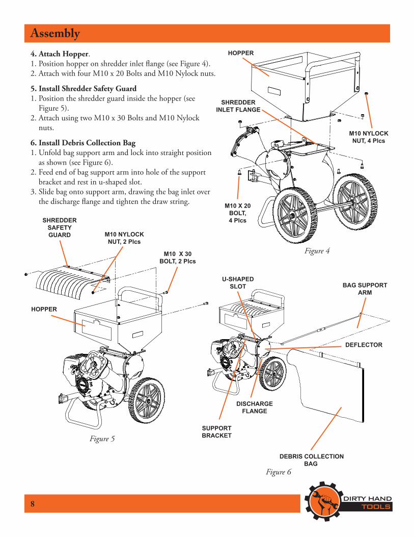
Assembly4. Attach Hopper.1. Position hopper on shredder inlet flange (see Figure 4).2. Attach with four M10 x 20 Bolts and M10 Nylock nuts.
5. Install Shredder Safety Guard1. Position the shredder guard inside the hopper (see
Figure 5).2. Attach using two M10 x 30 Bolts and M10 Nylock
nuts.
6. Install Debris Collection Bag 1. Unfold bag support arm and lock into straight position
as shown (see Figure 6). 2. Feed end of bag support arm into hole of the support
bracket and rest in u-shaped slot.3. Slide bag onto support arm, drawing the bag inlet over
the discharge flange and tighten the draw string. M10 X 20 BOLT, 4 Plcs
M10 NYLOCKNUT, 4 Plcs
HOPPER
Figure 4
Figure 5
M10 NYLOCK NUT, 2 Plcs
Figure 6
SHREDDER SAFETY GUARD
SHREDDER INLET FLANGE
M10 X 30 BOLT, 2 Plcs
HOPPER
BAG SUPPORT ARM
DEBRIS COLLECTION BAG
SUPPORTBRACKET
U-SHAPED SLOT
DEFLECTOR
DISCHARGE FLANGE
9
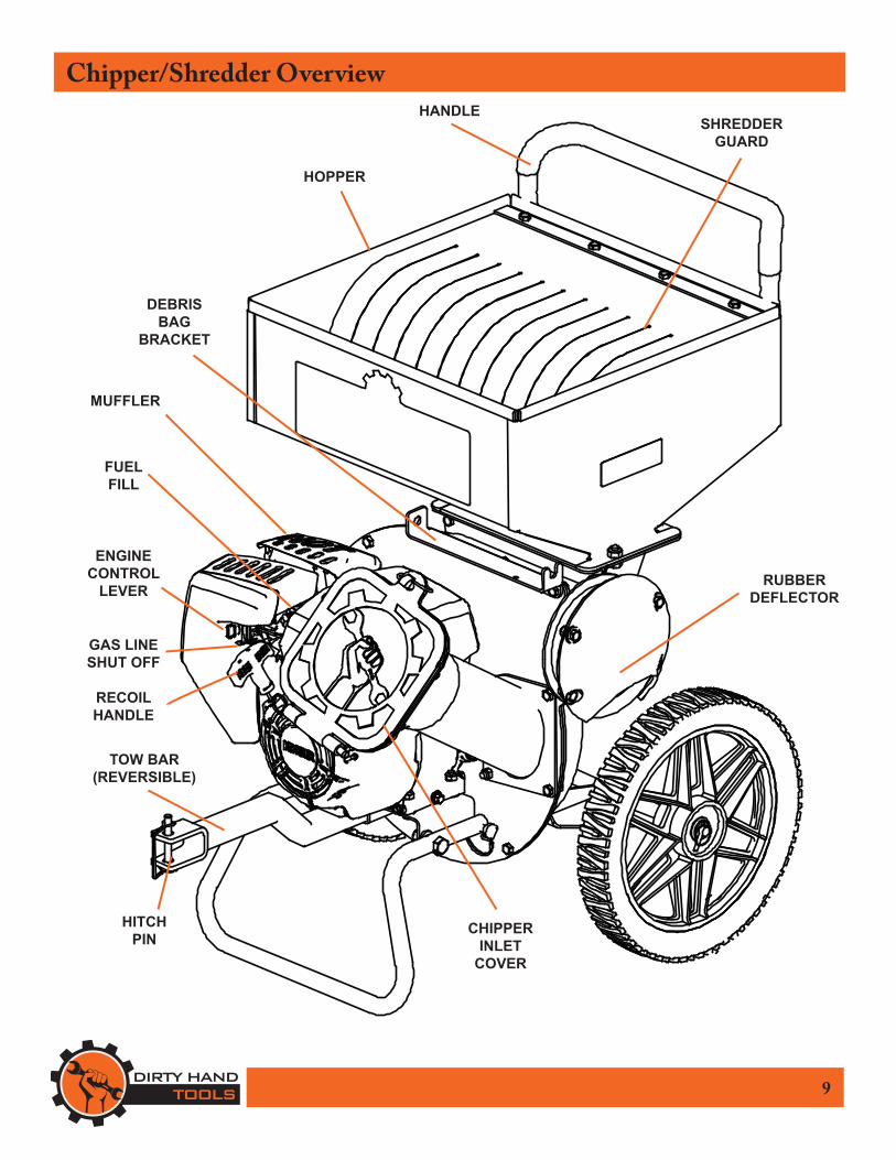
Chipper/Shredder Overview
RUBBERDEFLECTOR
MUFFLER
TOW BAR(REVERSIBLE)
CHIPPERINLET
COVER
SHREDDERGUARD
HOPPER
DEBRIS BAG
BRACKET
HITCHPIN
FUELFILL
GAS LINESHUT OFF
ENGINECONTROL
LEVER
HANDLE
RECOIL HANDLE
10
Operating Precautions
READ, UNDERSTAND AND FOLLOW ALL OF THE PRECAUTIONS BELOW.
Always perform the pre-start checklist before starting the engine.
• Never operate the chipper/shredder without safety guards and covers in place.
• Keep hands, feet, and clothing away from rotating parts. Keep clear of chipper/shredder tines at all times.
• Use extreme caution when operating on or crossing gravel drives, walks, or roads. Stay alert for hidden hazards or traffic.
• If a limb or branch becomes stuck in the chipper inlet or debris becomes clogged in the shredder hopper, stop the engine, remove the wire from the spark plug, manually remove the obstacle before restarting the engine.
• Engine muffler will be hot from operation. Do not touch it with bare skin or a severe burn may result.
• Do not run the engine indoors; exhaust fumes are deadly.• Do not overload the chipper/shredder by trying to process too much
debris at one time or force a limb in the chipper inlet that is a greater diameter than the machine’s capacity.
• Never operate the chipper/shredder on slippery surfaces. • Use only attachments and accessories approved by the manufacturer.• Never operate the chipper/shredder without good visibility or
adequate light.• Take precautions when leaving the machine unattended. Stop the
engine, wait for all moving parts to stop, and make certain guards and shields are in place.
• Shut off the engine when leaving the operating position for any reason. Wait for all moving parts to stop before attempting to dislodge debris, or limbs.
• The chipper/shredder blades are extremely sharp. Avoid contact with bare hands at all times.
!CAUTION
11
Operation
DO NOT ATTEMPT TO START ENGINEBEFORE ADDING OIL TO ENGINE
The engine is shipped from the factory without oil.
Use only the recommended weight of oil for a 4-cycle engine (See Engine Operation Manual).
NOTE: Upon start-up and shut-down, you may hear the metal-to-metal sound of the triangular hammers and J-hammers positioning themselves on the rotor. This is normal.
Chipper OperationThe chipper is designed to handle tree limbs and branches upto 3”. The chipping knives also permit the processing of coarse organic matter like corn stalks. Tree branches must be inserted large-end first into the chipper inlet. Since occasional kick-backs may occur, always stand off to the side of the unit. Allow the self-feeding action of the unit to draw the sticks in.
NOTE: CHALK THE WHEELS BEFORE OPERATION!
Shredder OperationThe shredder is designed to shred light brush, leaves, andother soft but bulky organic waste. As material, no larger than1/2 inch in diameter, is loaded into the shredder hopper it is pulled into the path of the triangular and J-hammers by air flow.
Operating LocationSelect an area with firm, level ground, covered by dirt or grass.Do not operate on wet or slick surfaces, or near bystanders.Locate and organize the materials to be processed so that youdon’t have to walk in front of the inlet or discharge openings,and so you have adequate room to work safely.
DO NOT ALLOW DEBRIS TO COLLECTON THE ENGINE.
A DANGER OF FIRE OR DAMAGETO THE ENGINE MAY RESULT.
!CAUTION
OILYOU MUST ADD ENGINE OIL BEFORE STARTING
THE ENGINE.
!CAUTION
12
Operation
Preparation for Operation
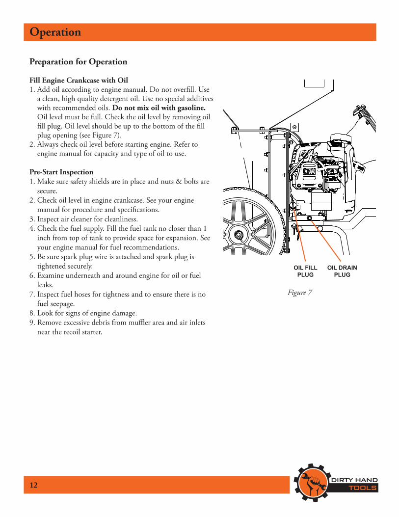
Fill Engine Crankcase with Oil1. Add oil according to engine manual. Do not overfill. Use
a clean, high quality detergent oil. Use no special additives with recommended oils. Do not mix oil with gasoline. Oil level must be full. Check the oil level by removing oil fill plug. Oil level should be up to the bottom of the fill plug opening (see Figure 7).
2. Always check oil level before starting engine. Refer to engine manual for capacity and type of oil to use.
Pre-Start Inspection1. Make sure safety shields are in place and nuts & bolts are
secure.2. Check oil level in engine crankcase. See your engine
manual for procedure and specifications.3. Inspect air cleaner for cleanliness.4. Check the fuel supply. Fill the fuel tank no closer than 1
inch from top of tank to provide space for expansion. See your engine manual for fuel recommendations.
5. Be sure spark plug wire is attached and spark plug is tightened securely.
6. Examine underneath and around engine for oil or fuel leaks.
7. Inspect fuel hoses for tightness and to ensure there is no fuel seepage.
8. Look for signs of engine damage.9. Remove excessive debris from muffler area and air inlets
near the recoil starter.
Figure 7
OIL DRAINPLUG
OIL FILL PLUG
13
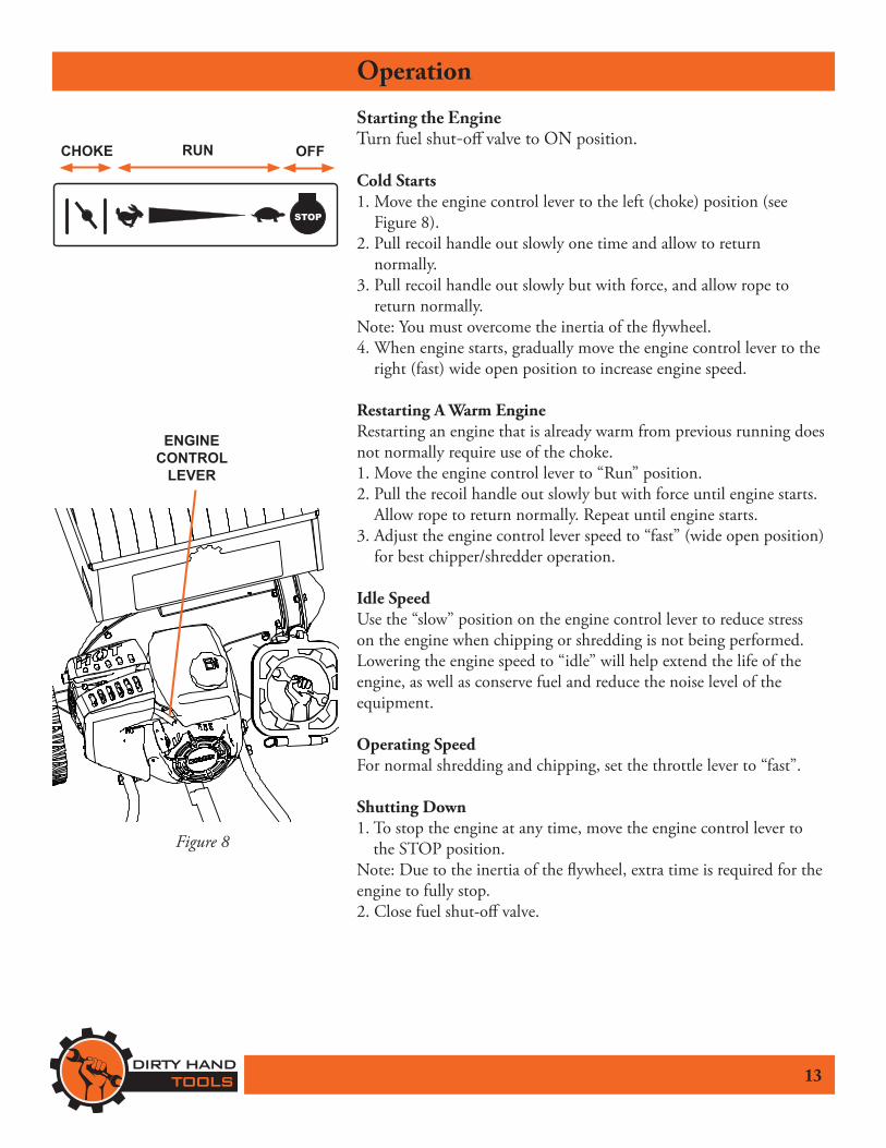
OperationStarting the EngineTurn fuel shut-off valve to ON position.
Cold Starts1. Move the engine control lever to the left (choke) position (see
Figure 8).2. Pull recoil handle out slowly one time and allow to return
normally.3. Pull recoil handle out slowly but with force, and allow rope to
return normally. Note: You must overcome the inertia of the flywheel.4. When engine starts, gradually move the engine control lever to the
right (fast) wide open position to increase engine speed.
Restarting A Warm EngineRestarting an engine that is already warm from previous running does not normally require use of the choke.1. Move the engine control lever to “Run” position.2. Pull the recoil handle out slowly but with force until engine starts.
Allow rope to return normally. Repeat until engine starts.3. Adjust the engine control lever speed to “fast” (wide open position)
for best chipper/shredder operation.
Idle SpeedUse the “slow” position on the engine control lever to reduce stress on the engine when chipping or shredding is not being performed. Lowering the engine speed to “idle” will help extend the life of the engine, as well as conserve fuel and reduce the noise level of the equipment.
Operating SpeedFor normal shredding and chipping, set the throttle lever to “fast”.
Shutting Down1. To stop the engine at any time, move the engine control lever to
the STOP position.Note: Due to the inertia of the flywheel, extra time is required for the engine to fully stop.2. Close fuel shut-off valve.
STOP
CHOKE RUN OFF
ENGINE CONTROL
LEVER
Figure 8
14
OperationChipping Recommendations• Prune branches down close to the main branch to make feeding them into the
chipper inlet easier.• Large, hard, dried tree branches that resist chipping can be processed by
rotating them as you alternately insert and retract them.• Material conditions vary, sometimes exceeding the capacity of the equipment.
If the material to be chipped is extremely hard, kicks back forcefully when being fed into the chipper inlet, or cannot be easily controlled, remove the material immediately and set it aside. Do not attempt to process these materials.
• If additional force is required to insert materials into the chipper, the blades probably need to be sharpened. Consult the Troubleshooting and Repair section of this manual, or see your authorized dealer.
• Maintain control of the materials you are feeding to prevent them from whipping around.
• Do not insert short pieces of material into the chipper inlet by hand. Use a larger piece of material to push them into the chipper inlet.
Shredding Recommendations• Don’t overload the shredder by dumping large volumes of material into the
hopper opening.• Alternate loads of wet and dry material to prevent the discharge from
becoming plugged.• Never use any object to force material into the shredding chamber. It could
get caught in the shredding hammers, kick back, whip around, or cause injury to the operator.
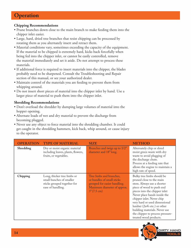
OPERATION TYPE OF MATERIAL SIZE METHOD Shredding Dry or moist organic material Branches and twigs up to 1/2” Alternately chip or shred including leaves, plants, flowers, diameter and 18” long. moist green waste with dry fruits, or vegetables. waste to avoid plugging of the discharge chute. Process at a feeding rate that allows the engine to maintain a high rate of speed. Chipping Long, thicker tree limbs or Tree limbs and branches, Bulky tree limbs should be small bunches of smaller or bundles of small sticks pruned close to the main sticks grouped together for grouped for easier handling. stem. Always use a shorter ease of handling. Maximum diameter of approx. piece of wood to push end 3” (7.5 cm) pieces into the chipper inlet Never place hands inside the chipper inlet. Never chip very hard or used dimensional lumber (2x4’s etc.) or other building materials. Never use the chipper to process pressure- treated wood products.

15
Maintenance
BEFORE PERFORMING ANY MAINTENANCE PROCEDURE STOP THE ENGINE, WAIT FIVE (5)
MINUTES TO ALLOW ALL PARTS TO COOL.Disconnect the spark plug wire,
keeping it away from the spark plug.
Regular maintenance is the way to ensure the best performance and long life of your machine. Please refer to this manual and theengine manufacturer’s owner’s manual for maintenance procedures.
!WARNING
Maintenance Before Every Every Procedure Each Use 25 Hours of Use 100 Hours of Use
Check engine oil level. Fill to correct level if necessary. X
Clean debris from engine exterior and X the air cleaner. Cleaning the engine air inlets near the recoil starter is critical for proper air flow.
Check general equipment condition X including guards, nuts, bolts, welds, etc.
Check chipper inlet and shredder hopper. These must be absolutely tight. X
Inspect chipping knives and rotate X shredding hammers.
Check safety labels. X
Change the engine oil X Clean/replace the air cleaner filter(s). X
Replace spark plug X
Maintenance Checklist

16
Maintenance
BEFORE PERFORMING ANY MAINTENANCE STOP THE ENGINE & ALLOW ALL PARTS TO COOL.
Disconnect the spark plug wire, keeping it away from the spark plug.
Engine MaintenanceRefer to the engine manual included with your equipment forinformation on engine maintenance. 1. Always check oil level before starting engine. Fill to correct level
if necessary.2. Change oil after first 5-8 hours of operation. Change oil while
engine is warm. Refill with new oil of recommended grade.3. Check spark plug yearly or every 50 hours of operation.4. Clean/replace air cleaner filter(s).5. Keep engine and parts clean.6. Check engine and equipment often for loose nuts and bolts, keep
these items tightened.7. Check that the safety labels are in place and undamaged.8. Check that the chipper inlet, shredder hopper, and discharge
guards are in place, undamaged and secure.
Changing the OilChange oil while engine is warm.1. Clean area around oil fill cap/dipstick and drain plug.2. Remove drain plug and oil fill cap/dipstick. Drain oil completely.3. Reinstall drain plug.4. Fill crankcase with new oil, up to point indicated on fill cap/
dipstick.5. Reinstall oil fill cap/dipstick and tighten securely.6. Dispose of used oil in accordance with local ordinances.
!WARNING
17
MaintenanceClean Debris from Engine & ChipperCheck for dirt and debris before each use and every 100 hours.The engine requires air flow to cool itself and for combustion.Before each use, clean any debris from the unit especially fromaround the air shroud intake, air filter, and muffler. Every 100hours, remove the engine air shroud and clean out any debrisfrom the engine cooling fins. We recommend having this service performed by an authorized dealer.
Cleaning/Replacing the Air Filter(s)NOTE: Operating engine with loose or damaged air cleaner components could cause premature wear and failure. Replace all bent or damaged components.
1. Unhook cover latch and remove air cleaner cover.2. Remove and replace paper element.3. Remove foam element; replace or wash in warm water with
detergent. Rinse and allow to air dry, then replace.4. Reinstall air cleaner cover and secure cover latch.
NOTE: Paper element cannot be blown out with compressed air.
Breather TubeEnsure both ends of breather tube are properly connected.
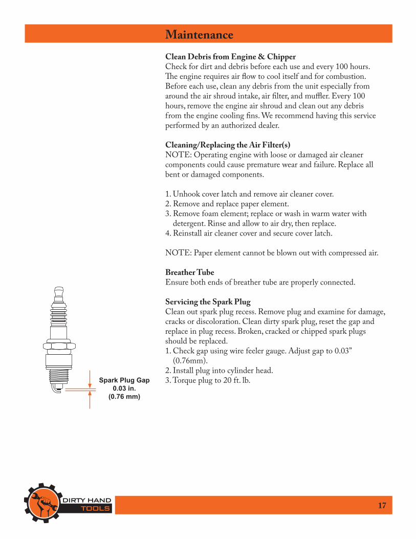
Servicing the Spark PlugClean out spark plug recess. Remove plug and examine for damage, cracks or discoloration. Clean dirty spark plug, reset the gap and replace in plug recess. Broken, cracked or chipped spark plugs should be replaced.1. Check gap using wire feeler gauge. Adjust gap to 0.03”
(0.76mm).2. Install plug into cylinder head.3. Torque plug to 20 ft. lb.Spark Plug Gap
0.03 in.(0.76 mm)
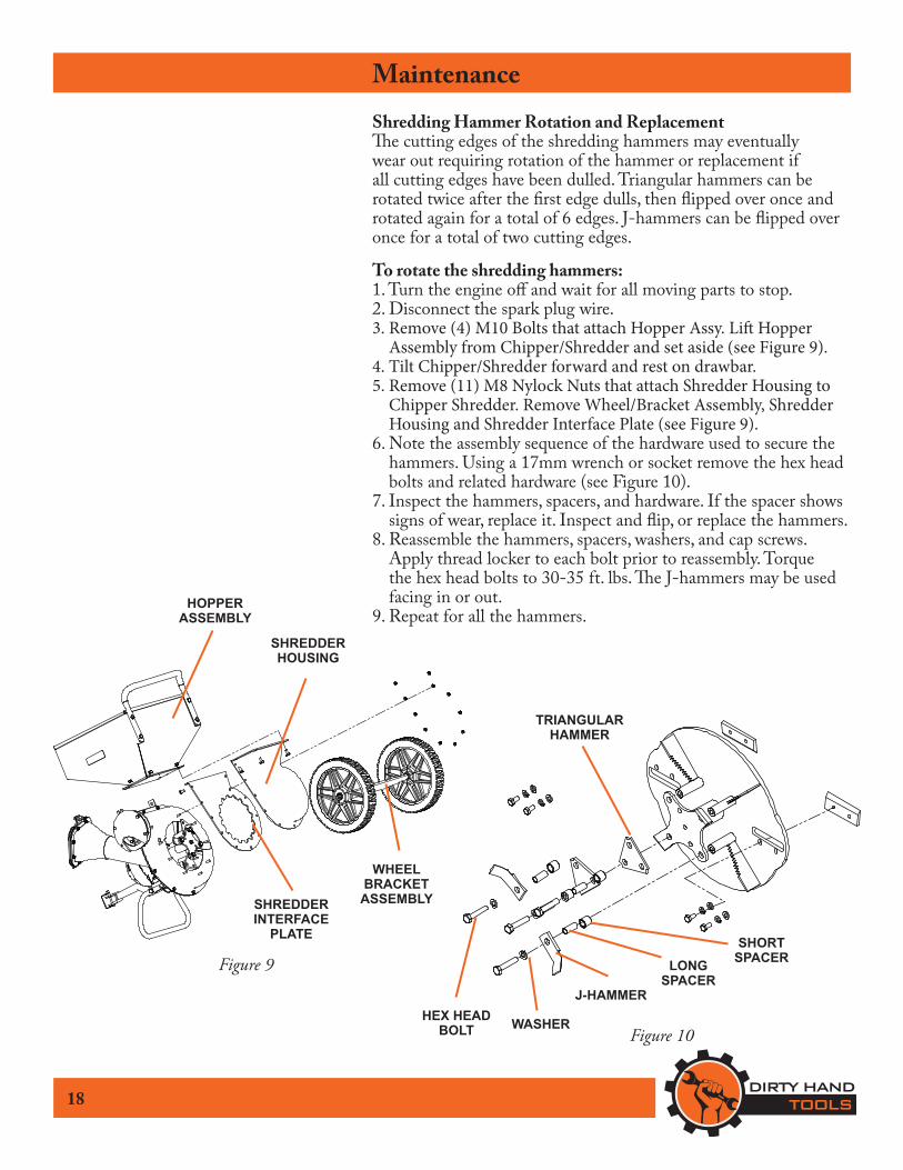
MaintenanceShredding Hammer Rotation and ReplacementThe cutting edges of the shredding hammers may eventuallywear out requiring rotation of the hammer or replacement ifall cutting edges have been dulled. Triangular hammers can be rotated twice after the first edge dulls, then flipped over once and rotated again for a total of 6 edges. J-hammers can be flipped over once for a total of two cutting edges.
To rotate the shredding hammers:1. Turn the engine off and wait for all moving parts to stop.2. Disconnect the spark plug wire. 3. Remove (4) M10 Bolts that attach Hopper Assy. Lift Hopper
Assembly from Chipper/Shredder and set aside (see Figure 9).4. Tilt Chipper/Shredder forward and rest on drawbar.5. Remove (11) M8 Nylock Nuts that attach Shredder Housing to
Chipper Shredder. Remove Wheel/Bracket Assembly, Shredder Housing and Shredder Interface Plate (see Figure 9).
6. Note the assembly sequence of the hardware used to secure the hammers. Using a 17mm wrench or socket remove the hex head bolts and related hardware (see Figure 10).
7. Inspect the hammers, spacers, and hardware. If the spacer shows signs of wear, replace it. Inspect and flip, or replace the hammers.
8. Reassemble the hammers, spacers, washers, and cap screws. Apply thread locker to each bolt prior to reassembly. Torque the hex head bolts to 30-35 ft. lbs. The J-hammers may be used facing in or out.
9. Repeat for all the hammers.
Figure 9
18
HEX HEAD BOLT WASHER
LONGSPACER
SHORTSPACER
J-HAMMER
TRIANGULAR HAMMER
Figure 10
HOPPERASSEMBLY
SHREDDERHOUSING
SHREDDERINTERFACE
PLATE
WHEEL BRACKET
ASSEMBLY
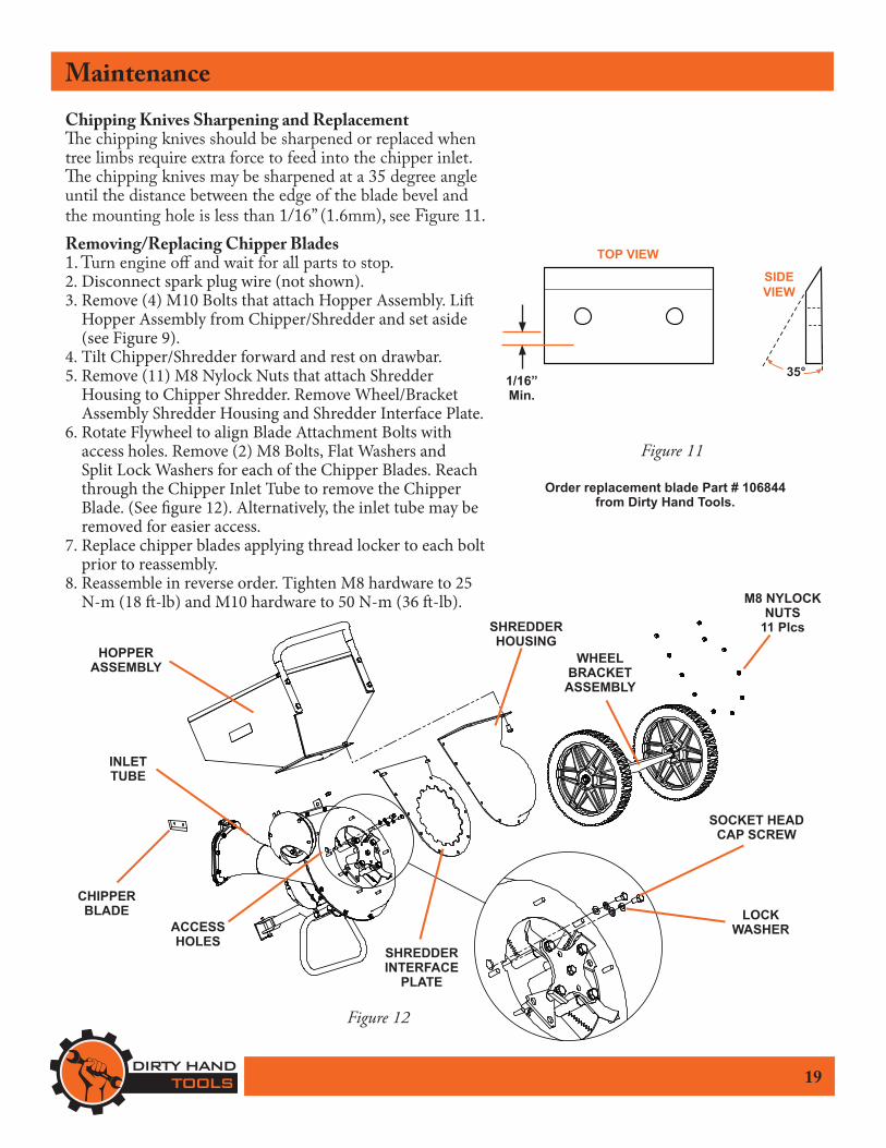
MaintenanceChipping Knives Sharpening and ReplacementThe chipping knives should be sharpened or replaced when tree limbs require extra force to feed into the chipper inlet. The chipping knives may be sharpened at a 35 degree angle until the distance between the edge of the blade bevel and the mounting hole is less than 1/16” (1.6mm), see Figure 11.Removing/Replacing Chipper Blades1. Turn engine off and wait for all parts to stop.2. Disconnect spark plug wire (not shown).3. Remove (4) M10 Bolts that attach Hopper Assembly. Lift
Hopper Assembly from Chipper/Shredder and set aside (see Figure 9).
4. Tilt Chipper/Shredder forward and rest on drawbar.5. Remove (11) M8 Nylock Nuts that attach Shredder
Housing to Chipper Shredder. Remove Wheel/Bracket Assembly Shredder Housing and Shredder Interface Plate.
6. Rotate Flywheel to align Blade Attachment Bolts with access holes. Remove (2) M8 Bolts, Flat Washers and Split Lock Washers for each of the Chipper Blades. Reach through the Chipper Inlet Tube to remove the Chipper Blade. (See figure 12). Alternatively, the inlet tube may be removed for easier access.
7. Replace chipper blades applying thread locker to each bolt prior to reassembly.
8. Reassemble in reverse order. Tighten M8 hardware to 25 N-m (18 ft-lb) and M10 hardware to 50 N-m (36 ft-lb).
Figure 11
LOCKWASHER
SOCKET HEAD CAP SCREW
CHIPPERBLADE
19
Figure 12
TOP VIEW
SIDEVIEW
35°1/16” Min.
SHREDDER INTERFACE
PLATE
SHREDDER HOUSING
HOPPERASSEMBLY
M8 NYLOCK NUTS
11 Plcs
ACCESSHOLES
WHEELBRACKET
ASSEMBLY
Order replacement blade Part # 106844from Dirty Hand Tools.
INLETTUBE
20
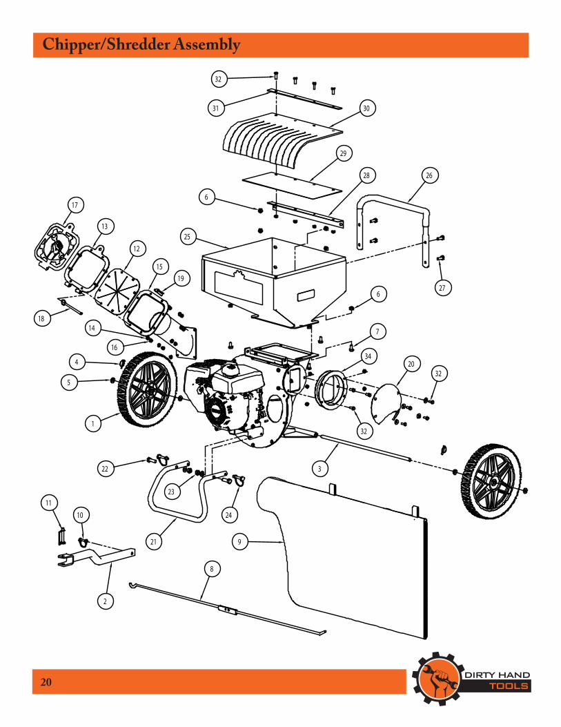
Chipper/Shredder Assembly
4
2
3
1
5
27
6
8
9
1011
12
13
14
15
16
17
18
19
20
21
22
23
24
25
26
7
6
28
29
3031
32
34
32
32
21
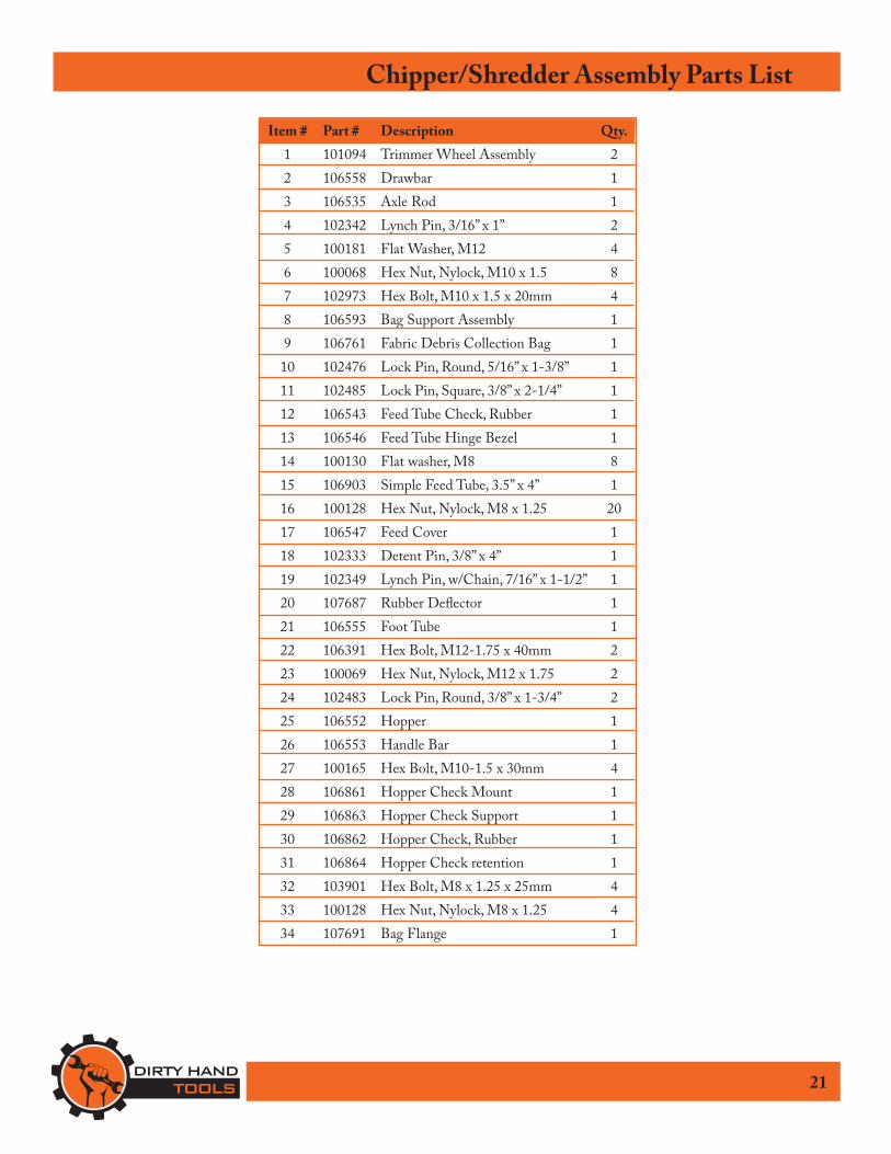
Chipper/Shredder Assembly Parts List
Item # Part # Description Qty. 1 101094 Trimmer Wheel Assembly 2 2 106558 Drawbar 1 3 106535 Axle Rod 1 4 102342 Lynch Pin, 3/16” x 1” 2 5 100181 Flat Washer, M12 4 6 100068 Hex Nut, Nylock, M10 x 1.5 8 7 102973 Hex Bolt, M10 x 1.5 x 20mm 4 8 106593 Bag Support Assembly 1 9 106761 Fabric Debris Collection Bag 1 10 102476 Lock Pin, Round, 5/16” x 1-3/8” 1 11 102485 Lock Pin, Square, 3/8” x 2-1/4” 1 12 106543 Feed Tube Check, Rubber 1 13 106546 Feed Tube Hinge Bezel 1 14 100130 Flat washer, M8 8 15 106903 Simple Feed Tube, 3.5” x 4” 1 16 100128 Hex Nut, Nylock, M8 x 1.25 20 17 106547 Feed Cover 1 18 102333 Detent Pin, 3/8” x 4” 1 19 102349 Lynch Pin, w/Chain, 7/16” x 1-1/2” 1 20 107687 Rubber Deflector 1 21 106555 Foot Tube 1 22 106391 Hex Bolt, M12-1.75 x 40mm 2 23 100069 Hex Nut, Nylock, M12 x 1.75 2 24 102483 Lock Pin, Round, 3/8” x 1-3/4” 2 25 106552 Hopper 1 26 106553 Handle Bar 1 27 100165 Hex Bolt, M10-1.5 x 30mm 4 28 106861 Hopper Check Mount 1 29 106863 Hopper Check Support 1 30 106862 Hopper Check, Rubber 1 31 106864 Hopper Check retention 1 32 103901 Hex Bolt, M8 x 1.25 x 25mm 4 33 100128 Hex Nut, Nylock, M8 x 1.25 4 34 107691 Bag Flange 1
22
Engine and Housing Assembly
1
2
3
4
56
7
8
9
10
11
12
13
14
1516
17
18

23
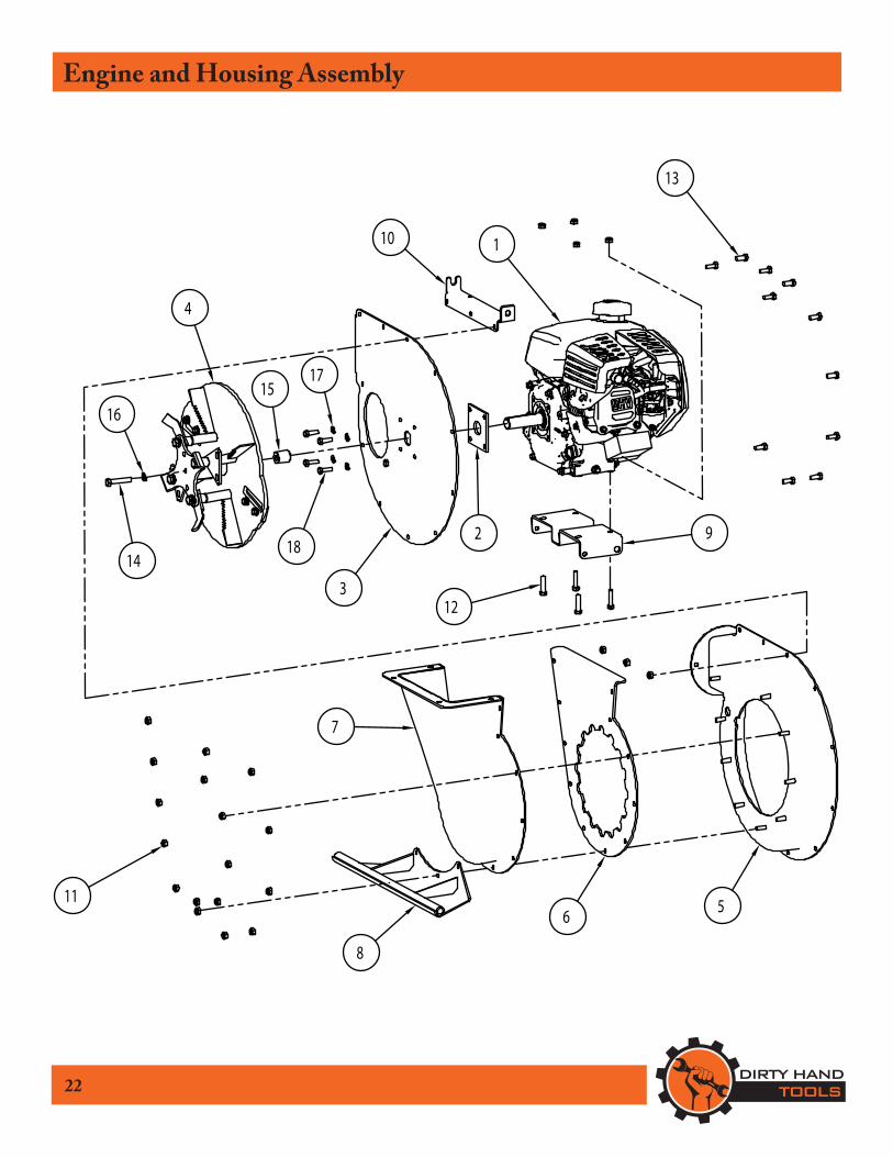
Engine and Housing Assembly Parts List
Item # Part # Description Qty. 1 107140 Engine Kohler, RH265, 1” Shaft 1 2 106559 Engine Spacer 1 3 106906 Feed Tube Closure 1 4 106571 Flywheel Assembly 1 5 106518 Chipper Housing 1 6 106515 Shredder Interface 1 7 106514 Shredder Housing 1 8 106533 Axle Bracket 1 9 106556 Drawbar Bracket 1 10 106530 Bag Arm Bracket 1 11 100128 Hex Nut, Nylock, M8 x 1.25 27 12 106808 Hex Bolt, M8 x 1.25X35mm 4 13 100125 Hex Bolt, M8 x 1.25X20mm 11 14 100021 Hex Head Bolt, 3/8-24 x 2” 1 15 106842 Flywheel Spacer 1 16 100611 Lock Washer, 3/8 1 17 100127 Lock Washer, M8 4 18 100486 Hex Head Bolt, 5/16 x 1, Z5 4
24
Chipper Rotor Assembly
9
2
13
810
7
11
5
4
6

25
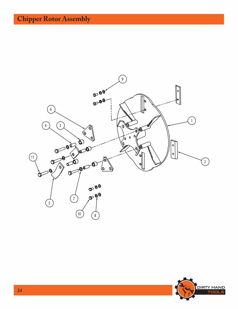
Chipper Rotor Assembly Parts List
Item # Part # Description Qty. 1 106566 Flywheel 1 2 106844 3.5” Chipper Blade 2 3 106570 Flail Spacer 4 4 106572 Flail Bushing 4 5 106569 J-Flail 2 6 106568 Trident Flail 2 7 100089 Lock Washer, M10 4 8 100127 Lock Washer, M8 4 9 100130 Flat Washer, M8 4 10 104986 Hex Bolt, M8 x 1.25 x 16mm 4 11 104365 Hex Bolt, M10 x 1.5 x 50mm 4
Troubleshooting
26
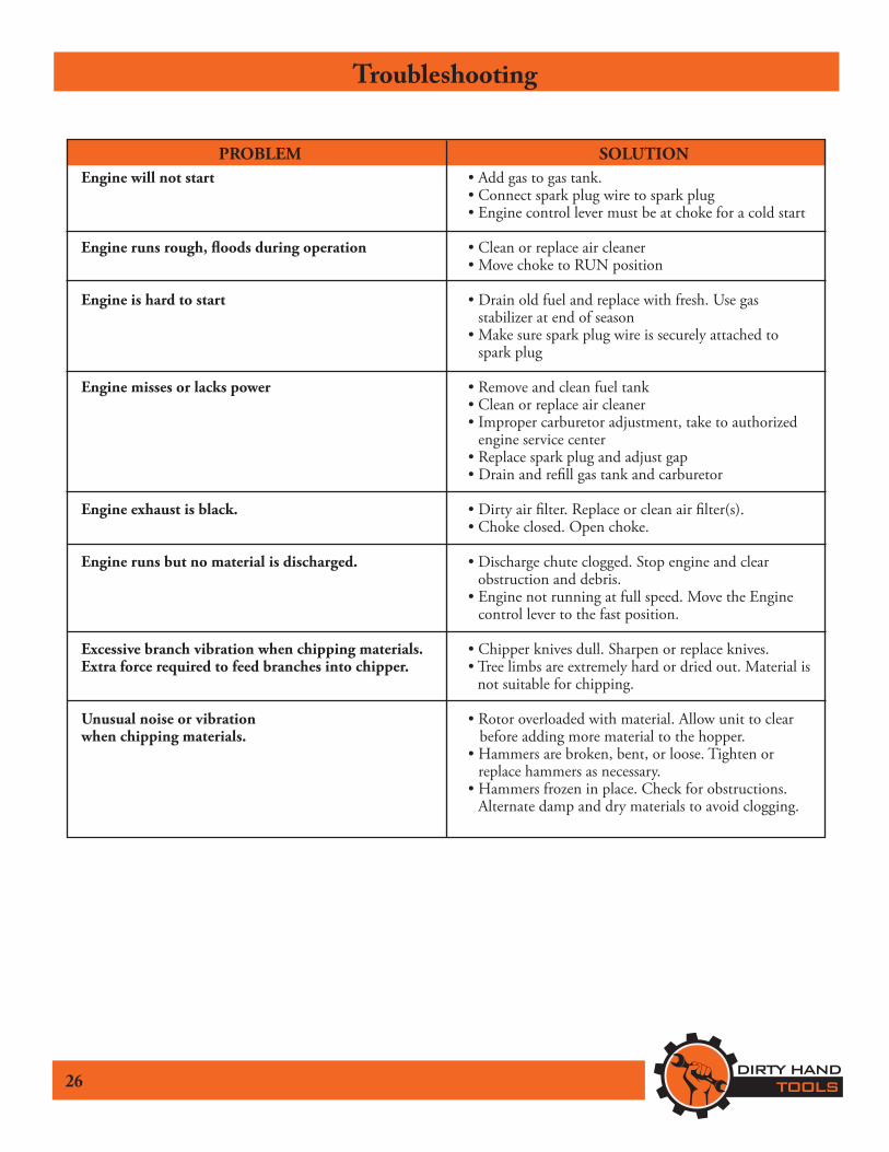
PROBLEM SOLUTIONEngine will not start • Add gas to gas tank. • Connect spark plug wire to spark plug • Engine control lever must be at choke for a cold start
Engine runs rough, floods during operation • Clean or replace air cleaner • Move choke to RUN position
Engine is hard to start • Drain old fuel and replace with fresh. Use gas stabilizer at end of season
• Make sure spark plug wire is securely attached to spark plug
Engine misses or lacks power • Remove and clean fuel tank • Clean or replace air cleaner • Improper carburetor adjustment, take to authorized
engine service center • Replace spark plug and adjust gap • Drain and refill gas tank and carburetor Engine exhaust is black. • Dirty air filter. Replace or clean air filter(s). • Choke closed. Open choke.
Engine runs but no material is discharged. • Discharge chute clogged. Stop engine and clear obstruction and debris.
• Engine not running at full speed. Move the Engine control lever to the fast position.
Excessive branch vibration when chipping materials. • Chipper knives dull. Sharpen or replace knives.Extra force required to feed branches into chipper. • Tree limbs are extremely hard or dried out. Material is
not suitable for chipping.
Unusual noise or vibration • Rotor overloaded with material. Allow unit to clearwhen chipping materials. before adding more material to the hopper. • Hammers are broken, bent, or loose. Tighten or
replace hammers as necessary. • Hammers frozen in place. Check for obstructions.
Alternate damp and dry materials to avoid clogging.
27
Storage
DO NOT STORE CHIPPER/SHREDDER INUNVENTILATED AREA
where fuel fumes may reach flame, sparks, pilot lightsor other ignition source.
Drain fuel outdoors away from any ignition sources. Use only approved fuel containers.
Prepare for StorageFollow the steps below to prepare your chipper/shredder for storage. Read your engine manual for detailed instructions on preparing the engine for storage.1. Protect wheels and axles from rust: Remove lock pin and slide
wheel off hub. Coat the axles lightly with axle grease. Slide wheel back on hub and insert lock pin.
2. Drain fuel system completely following engine manufacturer’s instructions or add fuel stabilizer to prevent fuel from gumming up during extended storage period.
3. While engine is still warm, drain the oil from the engine. Refill with fresh oil of the recommended grade.
4. Clean external surfaces, engine and cooling fan.5. Remove spark plug, pour one ounce of SAE 30 oil into spark
plug hole.6. Plug hole and pull starter cord slowly to distribute oil evenly in
cylinder head area.7. Reinstall spark plug. If there is any possibility of unauthorized
use or tampering, remove the spark plug and store it in a safe place before storing the chipper/shredder unit.
TransportingAlways use the hopper handle and built-in wheels to move the chipper shredder. Never lift the unit using the fuel tank for support. If the unit must be lifted, always use at least two people, and always grip the unit securely using the foot stand and hopper handle.
!WARNING

Warranty & Specifications IMPORTANT NOTICEWe, the manufacturer, reserve the right to change the product and/or specifications in this manual without notification. The manual is for information usage only and the pictures and drawings depicted herein are for reference only.
Warranty Repair and ServiceDo not return this product to the store for warranty issues or repair. Call our customer service department at 720-287-5182, 1-877-487-8275, or visit www.dirtyhandtools.com for the location of the nearest service center.
Record the information below for future reference.
Model No.Serial No.Date of PurchasePlace of Purchase
Specifications
1100 W 120th Ave., Suite 600Westminster, CO 80234 • 720-287-5182
Dirty Hand Tools® is a brand of For Service or QuestionsCall 1-877-487-8275720-287-5182www.dirtyhandtools.com
SKU/Part No. 108240 Description 3” Chipper/Shredder Engine Kohler RH265, 6.5 HP, 196cc* Starting System Manual, Recoil Chipping Capacity 3” Diameter Shredding Capacity 1/2” Hopper Size 20” x 19” x 7” Wheel Size 14” Diameter x 2” width Debris Collection 3 Bushel Capacity, Detachable Bag Debris Bag Size 42”L x 24”H (1064x600mm) Frame 10 Gauge Steel Dimensions 34”L x 24” W x 39.5” H (864x610x1080mm) Shipping Weight 220 Lbs. (99.8kg) Warranty 2 Year / 2 Year Limited Warranty
*As rated by engine manufacturer