2_ds_wise conference_uwb technology for wireless sensors in avionics
TRANSCRIPT
UWB technology for wireless sensors in avionics
Djordje SimicTechnical leader, RF system design
Arcachon, 17.06.2008

Copyright © 2008 16/06/2008
2
Overview
• Data transmission concepts• High data rate vs. low data rate• TES LDR UWB development• HDR systems – already here

Copyright © 2008 16/06/2008
What is Ultra-Wideband ?
• A wireless “technology” to quickly transmit very large amount of digital data over an extremely wide frequency spectrum at very low power and over short distances

Copyright © 2008 16/06/2008
Basics of UWB Signaling
Copyright © 2008 16/06/2008
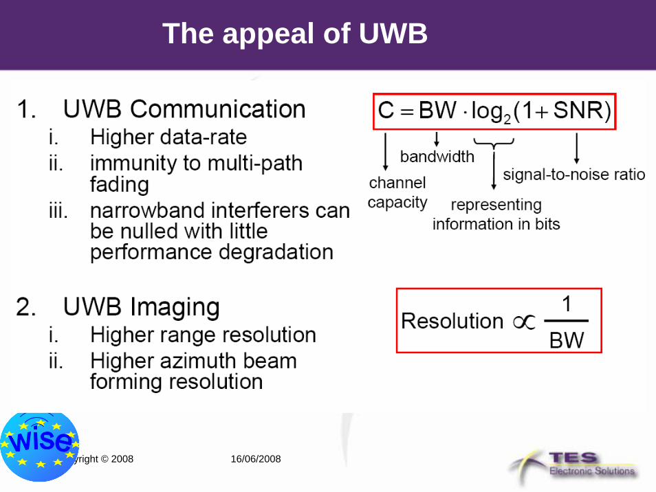
The appeal of UWB
Copyright © 2008 16/06/2008
Introduction to UWB-IR (Impulse Radio)
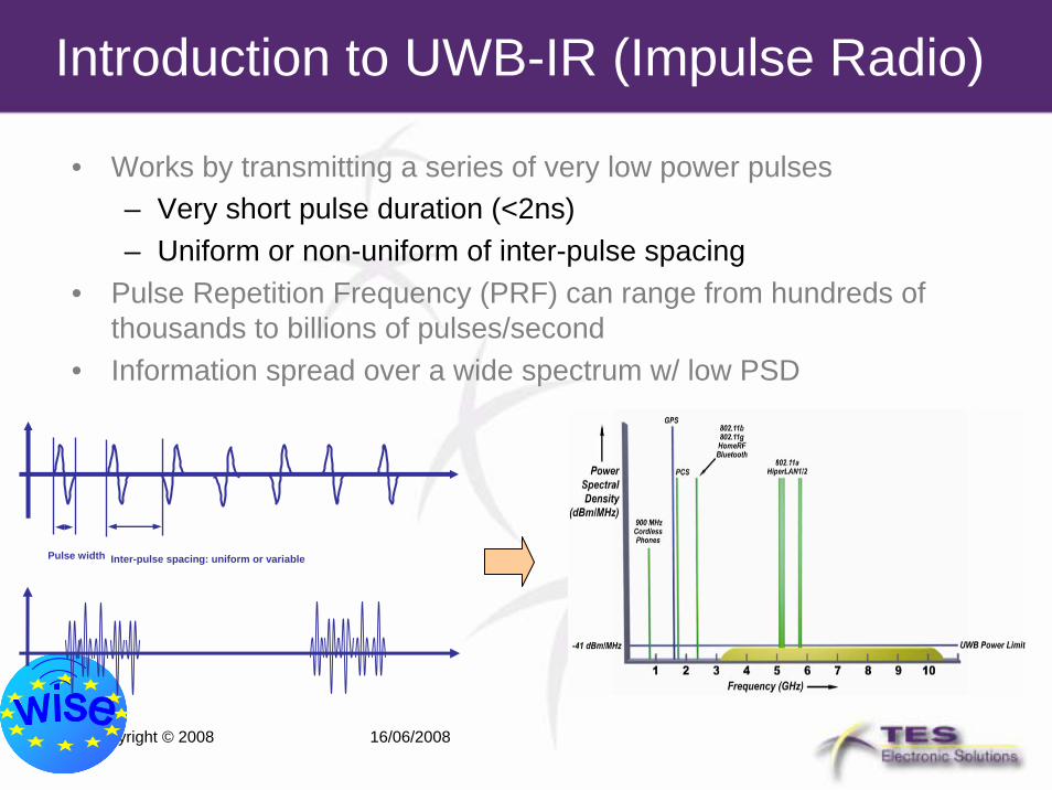
• Works by transmitting a series of very low power pulses– Very short pulse duration (<2ns)– Uniform or non-uniform of inter-pulse spacing
• Pulse Repetition Frequency (PRF) can range from hundreds of thousands to billions of pulses/second
• Information spread over a wide spectrum w/ low PSD
Pulse width Inter-pulse spacing: uniform or variable

Copyright © 2008 16/06/2008
IEEE 802.15.4a (UWB-IR) technology
• Alternate PHY for IEEE 802.15.4– Based on UWB-IR (Impulse Radio)
technology– Based on the “same” 802.15.4 MAC
• Smooth porting of existing Zigbee or other standard/proprietary stacks
• Main benefits vs. existing 2.4GHz 802.15.4 PHY:
– Precise ranging/locationing capability• <30 cm accuracy
– Inherent security (LPI/LPD)– Low active power consumption:
• Duty cycle <3.2%– Scalability:
• Performance/complexity (receiver structure) trade-off
– Data rate flexibility: 110kbps to 6.8/27.24 Mbps
– Multipath robustness
802.15.4a PHY
802.15.4 MACIEEE
Copyright © 2008 16/06/2008
Global UWB regulations for LDR systems
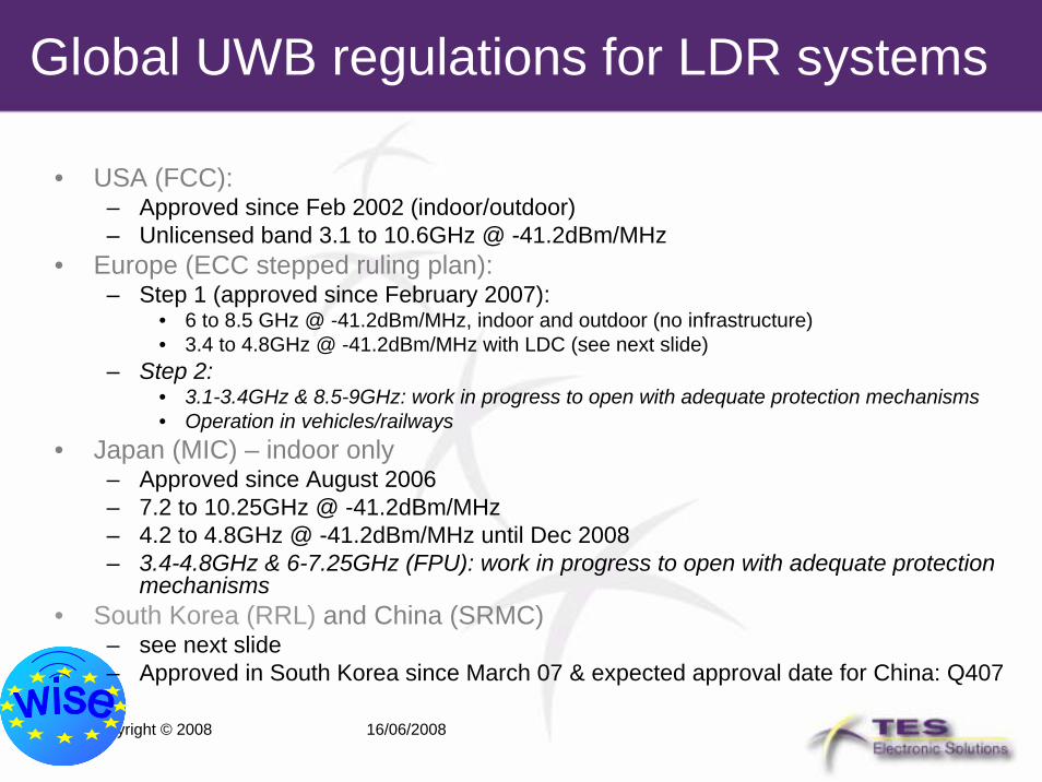
• USA (FCC):– Approved since Feb 2002 (indoor/outdoor)– Unlicensed band 3.1 to 10.6GHz @ -41.2dBm/MHz
• Europe (ECC stepped ruling plan):– Step 1 (approved since February 2007):
• 6 to 8.5 GHz @ -41.2dBm/MHz, indoor and outdoor (no infrastructure)• 3.4 to 4.8GHz @ -41.2dBm/MHz with LDC (see next slide)
– Step 2:• 3.1-3.4GHz & 8.5-9GHz: work in progress to open with adequate protection mechanisms• Operation in vehicles/railways
• Japan (MIC) – indoor only– Approved since August 2006– 7.2 to 10.25GHz @ -41.2dBm/MHz– 4.2 to 4.8GHz @ -41.2dBm/MHz until Dec 2008– 3.4-4.8GHz & 6-7.25GHz (FPU): work in progress to open with adequate protection
mechanisms• South Korea (RRL) and China (SRMC)
– see next slide– Approved in South Korea since March 07 & expected approval date for China: Q407
Copyright © 2008 16/06/2008
5
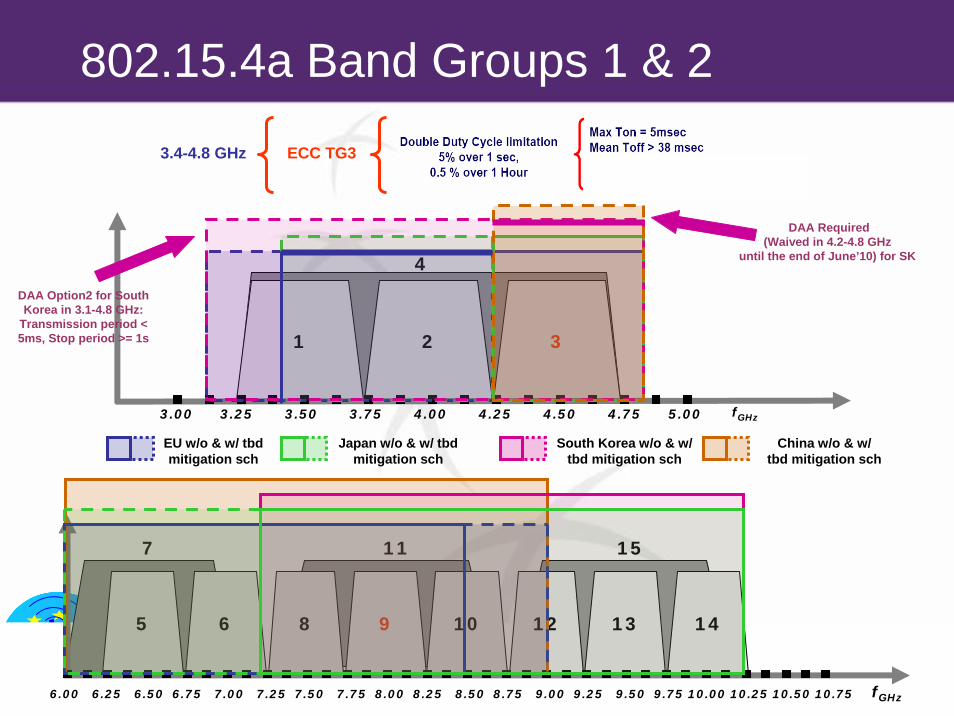
802.15.4a Band Groups 1 & 2
2 321
3.00 3.25 3.50 3.75 4.00 4.25 4.50 4.75 5.00 fGHz
4
44 10 129 14136 8
6.00 6.25 6.50 6.75 7.00 7.25 7.50 7.75 8.00 8.25 8.50 8.75 9.00 9.25 9.50 9.75 10.00 10.25 10.50 10.75 fGHz
117 15
EU w/o & w/ tbdmitigation sch
Japan w/o & w/ tbdmitigation sch
South Korea w/o & w/ tbd mitigation sch
China w/o & w/ tbd mitigation sch
ECC TG33.4-4.8 GHz
DAA Require(Waived in 4.2-4.8 GHz
until the end of June
DAA Option2 for South Korea in 3.1-4.8 GHz:
Transmission period < 5ms, Stop period >= 1s
d
’10) for SK

Copyright © 2008 16/06/2008
IEEE 802.15.4(a) application positioning
Range
Effe
ctiv
e th
roug
hput
Closer
WiMedia™
Farther
Slow
erFa
ster
Wireless Data Applications
Wireless Video
Applications
802.11g
802.11b
802.11a
2.5G/3G
Bluetooth™
IEEE802.15.4(a)
Wireless Sensors
Wireless Networking
Wi-Fi®
Copyright © 2008 16/06/2008
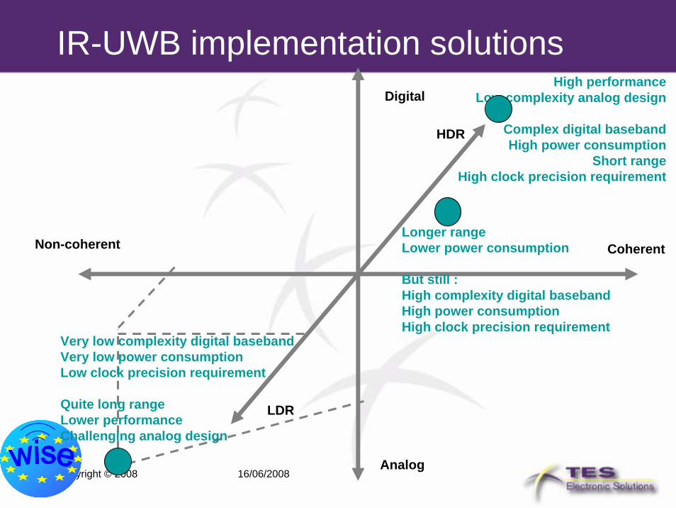
IR-UWB implementation solutionsDigital
Non-coherent Coherent
Analog
High performanceLow complexity analog design
Complex digital basebandHigh power consumption
Short rangeHigh clock precision requirement
Very low complexity digital basebandVery low power consumptionLow clock precision requirement
Quite long range Lower performanceChallenging analog design
LDR
HDR
Longer rangeLower power consumption
But still :High complexity digital basebandHigh power consumptionHigh clock precision requirement

Copyright © 2008 16/06/2008
UWB IC
Simplified UWB transciever architecture
ADCPGAFGALNA
FPGABaseband
LPFBPF
PulseGeneratorBufferBPFPA
ClockGenerator
Receiver
13
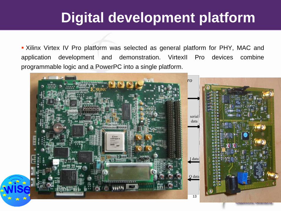
Xilinx Virtex IV Pro platform was selected as general platform for PHY, MAC and application development and demonstration. VirtexII Pro devices combine programmable logic and a PowerPC into a single platform.
UWB silicon
FPGA
MCU
control interface register set
TX side(Pulser)
data interface
RX side(U2-one)
data interface
serialdata
I data
Q datamap
per
SHR detector
control bus
RX bus
headerdetect
serial/parallelconversion
parallel/serialconversion
TX bus
MAC unitapp unit
CCA mechanism
ALOHAor
CCA-CSMA
VirtexII Pro
Digital development platform
Copyright © 2008 16/06/2008
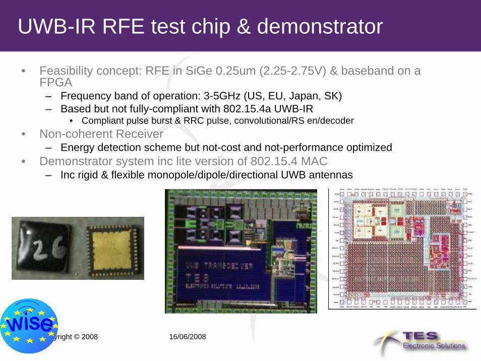
UWB-IR RFE test chip & demonstrator
• Feasibility concept: RFE in SiGe 0.25um (2.25-2.75V) & baseband on a FPGA
– Frequency band of operation: 3-5GHz (US, EU, Japan, SK)– Based but not fully-compliant with 802.15.4a UWB-IR
• Compliant pulse burst & RRC pulse, convolutional/RS en/decoder• Non-coherent Receiver
– Energy detection scheme but not-cost and not-performance optimized• Demonstrator system inc lite version of 802.15.4 MAC
– Inc rigid & flexible monopole/dipole/directional UWB antennas

Copyright © 2008 16/06/2008
15
UWB IC test boards developed during WISE

Copyright © 2008 16/06/2008
Pulse generatorGenerates a pair of pulses in duration of main clock half-period. Suitable for On-off keying or Pulse-Position Modulation.The signal can be used for up-conversion for use in other frequency bands (e.g. 60 GHz)Requires out of chip filtering to fit in regulation mask.Master-slave D-type flip-flop (MS-DFF)with substractor– Pseudo “Manchester-encoded” data inputup to 500 Mbps– Rise and fall edges of encoded data inputgenerate pulses– Pulse duration & position dependent onclock frequency/phase offset• 1GHz to 10GHz reference clock input
Input data
Outputpulse
Subtractor
D-FF
PulseGenerator
PulseOutput
D-FFDataInput
ClockInput
VDD VSS

Copyright © 2008 16/06/2008
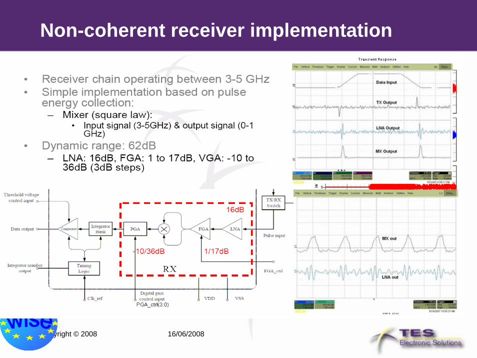
Receiver architecture
LNAFGAPGAIntegrator
bank COMP2
UWB_RX
SYN_Dout
CH_Q
DAC_D VGA2_ctrl FGA_CTRL
Gain Selection Logic
Digital Logic Control
Synchronisation
End-of-AGC
Detection
CLK+δDigital Clock Manager
CLK+90º
CLK+180º
CLK+270º
CLK
Reference clock
Sys_CLK
TH
– Energy detection based non-coherent receiver– Gain chain control distributed before and aftermixer that acts as square law device in order to optimize the dynamic range– Energy detection performed by bank of 8 Integrators that follow square-law device– Embedded digital logic perfroms OOK demodulation. PPM demodulation can beperformed using external circuitry– By controlling the system clock phase betterresolution in time can be achieved what isimportant for ranging applications
Copyright © 2008 16/06/2008
Non-coherent receiver implementation
Copyright © 2008 16/06/2008
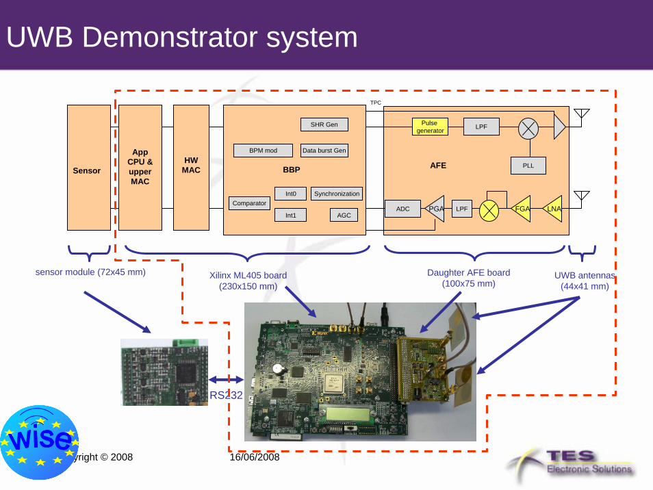
UWB Demonstrator system
Pulse generator
PLL
LPF
LNAFGALPFADC
AFE
PGAComparator
SynchronizationInt0
AGC
BBPHW
MAC
App CPU & upper MAC
Sensor
Daughter AFE board (100x75 mm)
Int1
Data burst Gen
SHR Gen
BPM mod
TPC
Xilinx ML405 board (230x150 mm)
UWB antennas (44x41 mm)
RS232
sensor module (72x45 mm)

Copyright © 2008 16/06/2008
PHY parameters• Platform development for data communication in
sensor networks using UWB technology• PHY implementation• Digital part:
– IEEE 802.15.4a alike <Preamble><SFD><PhyHeader><Data>
– Data rate: 110kbit/s, 850kbit/s– Packet size up to 127 bytes
• RF part: – Band 3-5 GHz, Central frequency 4.5 GHz– Bandwidth 500 MHz– Total transmit power (max) -10dBm– Receiver sensitivity (PER 1%) –70dBm

Copyright © 2008 16/06/2008
Transmitter Output
• One packet at Tx output with preamble, SFD, and data part (timebase of lower part 50ns/div).
RF signal / preamble
BB control Single end / preamble

Copyright © 2008 16/06/2008
Digital BB PHY Implementation
• Xilinx FPGA Device Virtex 4, XC4VFX20• Slices 8544• Speed Grade -10• Synthesis Tool XST of ISE 9.2 / Synplify Pro
• Part LUT FF• PHY without FEC (RS, SECDED) 2914 1294• FEC 1671 1162• % of total 17088 LUT/FF 27% 15%
Copyright © 2008 16/06/2008
LDR outlook• PHY layer implementation of the non-coherent UWB• Hardware implementation of analogue front-end
circuitry• Digital PHY has been implemented verified on VHDL
and circuit level, with accompanying measurements on ML405 development platform.
• Test application for PHY evaluation• The same digital platform is going to be used in MAC
and application implementation and will enable the system integration.
• Further work will also address improvement of PHY layer performance by implementing interference rejection-mitigation processing.
Copyright © 2008 16/06/2008
LDR UWB performance for the market– IEEE-802.15.4a full conformance– Transceiver + HMAC + AES encryption engine on the same die:
• CMOS090 preferably– Mandatory PRF only: 15.6M & 3.90MHz & all associated data rates– Normal & wideband signal support (0.5GHz/1.3GHz):
• Larger absolute bandwidth & higher SNR (localization accuracy) + longer range
• Larger relative bandwidth for better penetration– No pulse spectral shaping or optional TD pulse combo– -91 dBm sensitivity for 100kb/s:
• Likely to be a coherent receiver– Adjustable resolution window (down to sub 3ns) for sub-meter ranging
capability– Die size:
• <9.5mm2 for the whole Trx/HMAC/AES function– Power consumption
• <18mA @3V (average) for both Tx/Rx, STB < 2uA– Preamble repetition: 64 & 1024 at a minimum (4096 as a nice to have if
non-coherent approach gets selected), 8-symbol SFD only– No private ranging and no preamble time-multiplexing

Copyright © 2008 16/06/2008
UWB System communication capability in different propagation environment
•Partial band implementation (in this case 2 GHz bandwidth) eases implementation and allows smaller antennas and smaller system size.
• Usage of simple detection techniques relaxes demanded Eb/No
•Channel capacity of 1 Mbit/s is provided at distance of 10m even for severe channel conditions (n=3.5)
•Channel capacity of 1 Kbit/s is provided at distance of 80m even for severe channel conditions (n=3.5)
Figure shows channel capacity in function of link distance for several propagation channels.
Copyright © 2008 16/06/2008
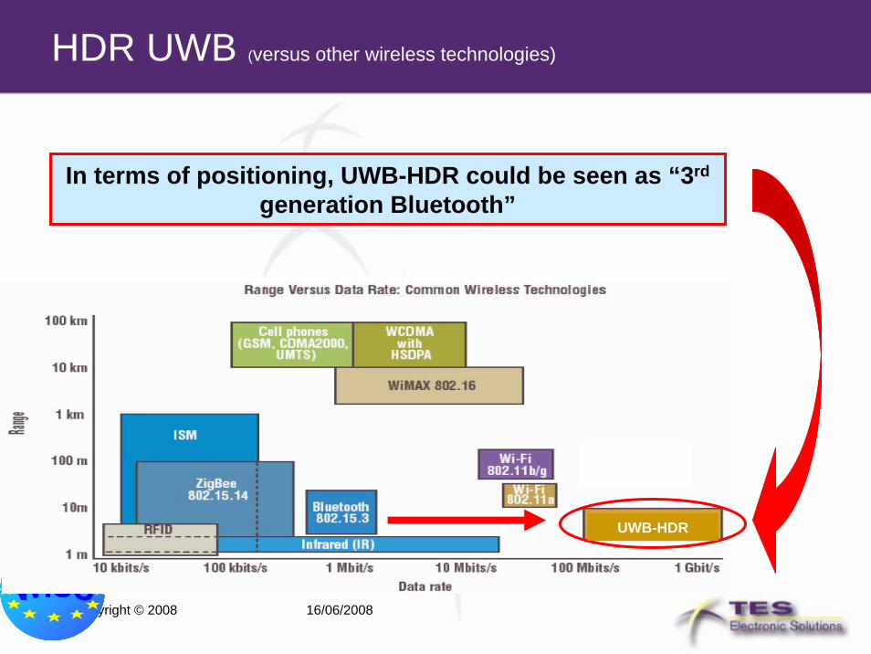
HDR UWB (versus other wireless technologies)
In terms of positioning, UWB-HDR could be seen as “3rd
generation Bluetooth”
UWB-HDR
Copyright © 2008 16/06/2008
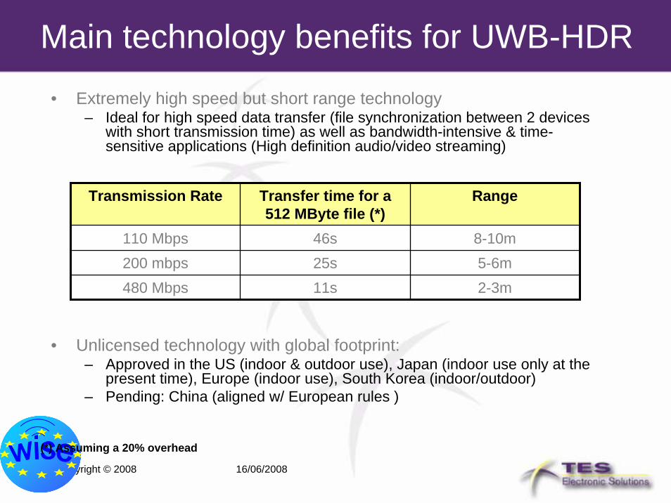
Main technology benefits for UWB-HDR
• Extremely high speed but short range technology– Ideal for high speed data transfer (file synchronization between 2 devices
with short transmission time) as well as bandwidth-intensive & time-sensitive applications (High definition audio/video streaming)
• Unlicensed technology with global footprint:– Approved in the US (indoor & outdoor use), Japan (indoor use only at the
present time), Europe (indoor use), South Korea (indoor/outdoor)– Pending: China (aligned w/ European rules )
Transmission Rate Transfer time for a 512 MByte file (*)
Range
110 Mbps 46s25s11s
8-10m200 mbps 5-6m480 Mbps 2-3m
(*) Assuming a 20% overhead
Copyright © 2008 16/06/2008
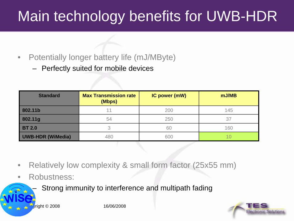
Main technology benefits for UWB-HDR
• Potentially longer battery life (mJ/MByte)– Perfectly suited for mobile devices
• Relatively low complexity & small form factor (25x55 mm)• Robustness:
– Strong immunity to interference and multipath fading
Standard Max Transmission rate (Mbps)
IC power (mW) mJ/MB
802.11b 11 200 145
802.11g 54 250 37
BT 2.0 3 60 160
UWB-HDR (WiMedia) 480 600 10
Copyright © 2008 16/06/2008
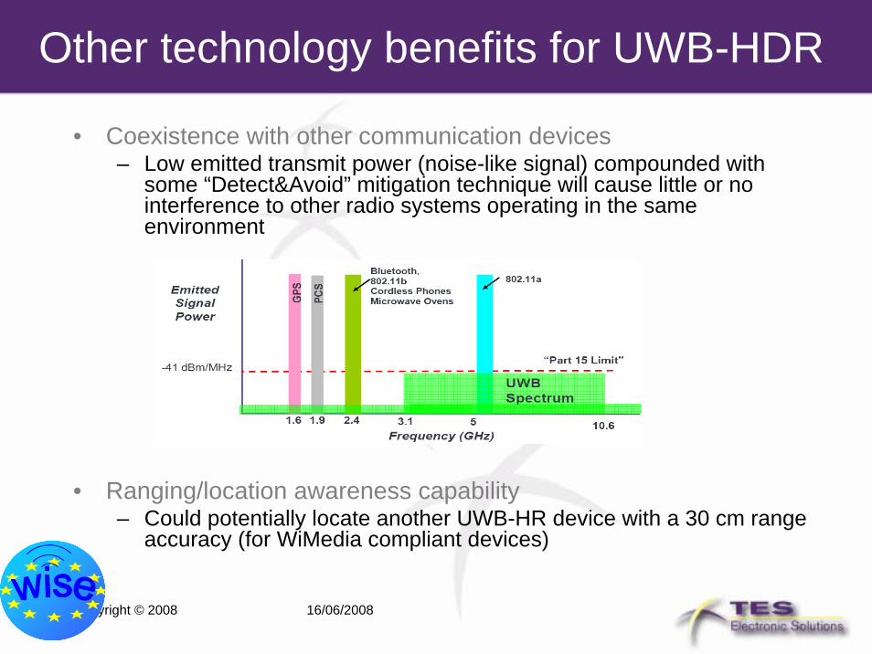
Other technology benefits for UWB-HDR
• Coexistence with other communication devices– Low emitted transmit power (noise-like signal) compounded with
some “Detect&Avoid” mitigation technique will cause little or no interference to other radio systems operating in the same environment
• Ranging/location awareness capability– Could potentially locate another UWB-HR device with a 30 cm range
accuracy (for WiMedia compliant devices)

Copyright © 2008 16/06/2008
30
Conclusion
• UWB systems provide large variety of solutions for communication and sensing applications without need for operation licenses
• In scope of the WISE project a LDR UWB demonstrator system has been developed
• During the WISE project the standardization and regulation processes in Europe have been closed
• Current status of the LDR development is still not mature enough for commercial applications
• High data rate UWB systems already exist on the market as excellent solution for high speed data transfer over short distances