2d shape analysis of mandible outlines in fossil …
TRANSCRIPT

2D SHAPE ANALYSIS OF MANDIBLE OUTLINES IN FOSSIL HOMININS UTILIZING
SYNTHESIS TECHNIQUES FROM PLANAR MECHANISM DESIGN
1
Bingjue Li1, Andrew P. Murray2, David H. Myszka2, Gérard Subsol3
1 JiangSu Key Lab. For Design and Manufacture of Micro-Nano Biomedical Instruments, School of mechanical Engineering, Southeast University, Nanjing, China
2 DIMLab, Department of Mechanical and Aerospace Engineering, Univ. of Dayton, USA3 Research-Team ICAR, LIRMM, Univ. Montpellier, CNRS, France
June 25, 2019
International Symposium on Biological Shape Analysis

2
❑Introduction
❑Methodology for planar mechanism design
❑Applications
❑Future work

3
Outline-based Morphometrics
4
Outline-based Morphometrics
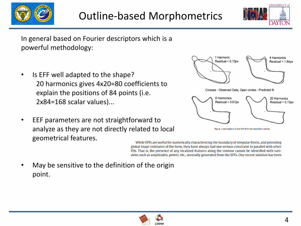
In general based on Fourier descriptors which is a powerful methodology:
• Is EFF well adapted to the shape?20 harmonics gives 4x20=80 coefficients to explain the positions of 84 points (i.e. 2x84=168 scalar values)...
• EEF parameters are not straightforward to analyze as they are not directly related to local geometrical features.
• May be sensitive to the definition of the origin point.

5
A New Method
• New method based on mechanical considerations…..
• Planar shape changing rigid-body mechanisms
• Mechanism: revolute joints (pivot) / prismatic joints (glissière) which parameters are easy to understand.
B. Li, A.P. Murray, D.H. Myszka, G. Subsol. "Synthesizing Planar Rigid-Body Chains for Morphometric Applications". ASME International Design Engineering TechnicalConferences & Computers and Information in Engineering Conference, Charlotte (U.S.A.), August 2016.

6
Categorization of Profiles
Open Closed
12
3
12
3

7
The Goal
Desired shapes
Profile 1
Profile 2
Profile 3

8
The Goal
Revolute joint
C-segment (links containing prismatic joints)
M-segment
Fused connection
Chain of rigid bodies

2 C segments + 3 R joints = 5 scalar parameters

10
❑Introduction
❑Methodology for planar mechanism design
❑Applications
❑Future work
11
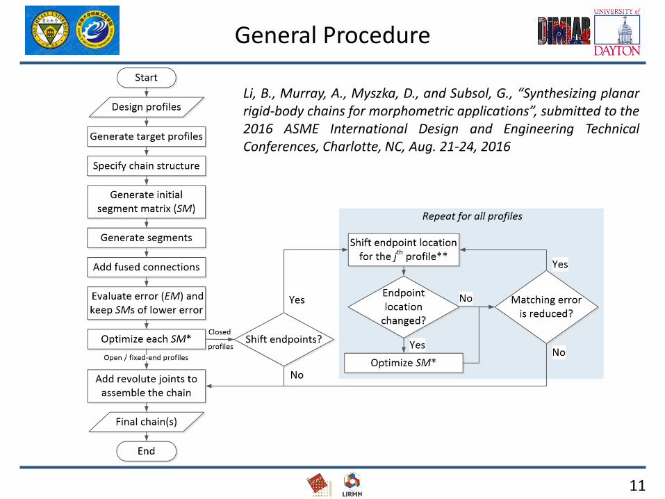
General Procedure
Li, B., Murray, A., Myszka, D., and Subsol, G., “Synthesizing planarrigid-body chains for morphometric applications”, submitted to the2016 ASME International Design and Engineering TechnicalConferences, Charlotte, NC, Aug. 21-24, 2016
12
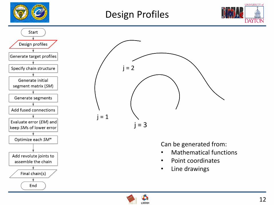
Design Profiles
Can be generated from:• Mathematical functions• Point coordinates• Line drawings
j = 1
j = 2
j = 3

13
Target Profiles
1. Compute the arc length of each design profile
2. Determine the number of pieces should be in each target profile
3. Desired piece length of target profile
2000 pieces
2322 pieces
2253 piecesj = 1
j = 2
j = 3
14
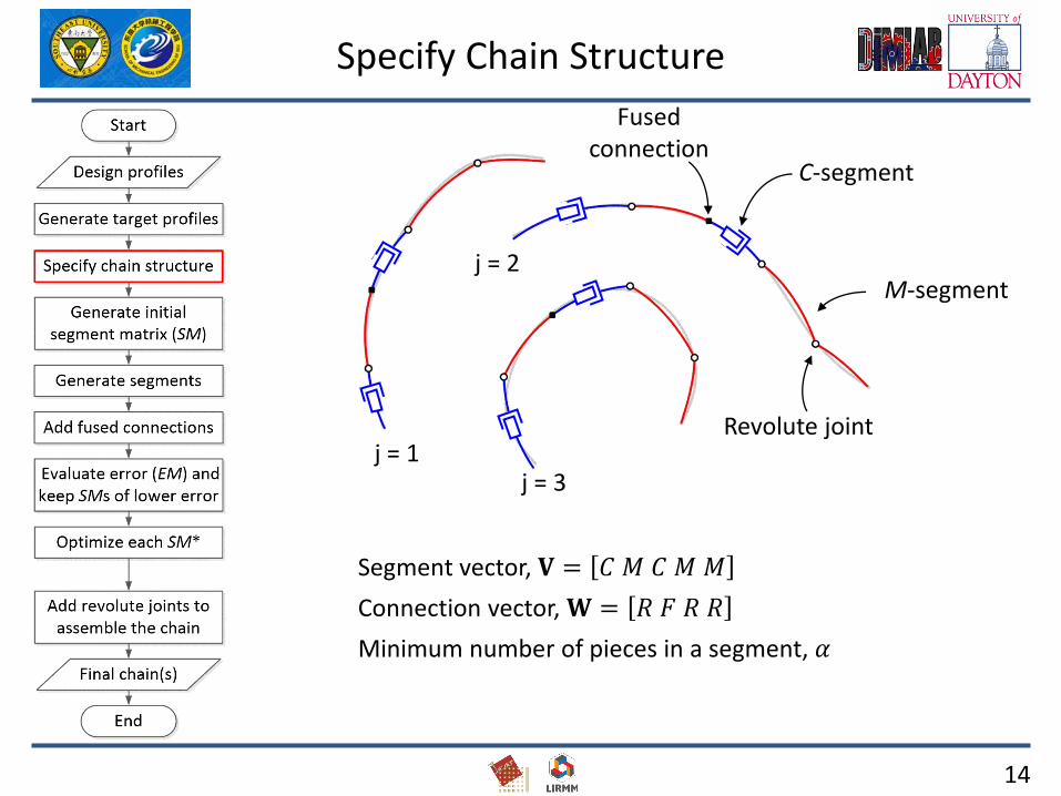
Specify Chain Structure
Segment vector, 𝐕 = 𝐶 𝑀 𝐶 𝑀 𝑀
Connection vector, 𝐖 = 𝑅 𝐹 𝑅 𝑅
Minimum number of pieces in a segment, 𝛼
j = 1
j = 2
j = 3
C-segment
M-segment
Revolute joint
Fused connection

15
Initial Segment Matrices (SM)
V = [ C M C M M ]
𝑆𝑀 =359506346
596596596
337512603
343343343
365365365
𝑗 = 1𝑗 = 2𝑗 = 3
j = 1
j = 2
j = 3
Segmentation points
359
596
337
343365
346
596
603
343
365
506 596
512
343
365

Actual segment point coordinates
16
Generating Segments
M-Segments
Finding average geometry

17
Generating Segments
C-Segments
Average radius (reciprocal of curvature)
Segment arc length
Average piece length
ҧ𝑟𝑒
ҧ𝑠𝑒
𝛿
(0, ҧ𝑟𝑒)
(0,0)

M-segment
C-segment
𝜃𝑗,𝑒
18
Generate Segments
V = [ C M C M M ]
𝑆𝑀 =359506346
596596596
337512603
343343343
365365365
𝑗 = 1𝑗 = 2𝑗 = 3
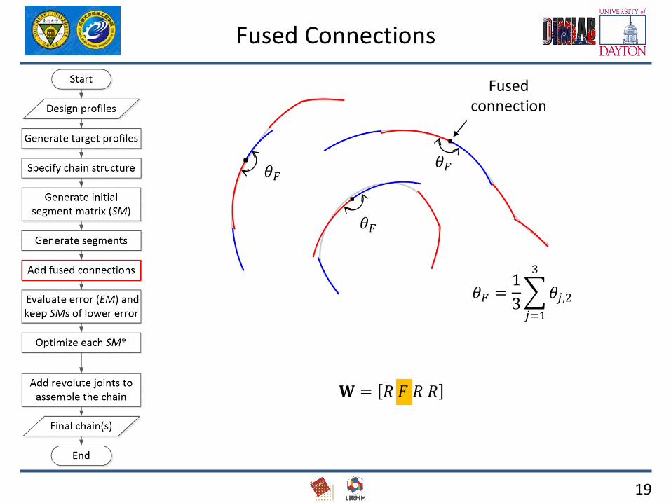
Fused connection
𝐖 = 𝑅 𝐹 𝑅 𝑅
𝜃𝐹 =1
3
𝑗=1
3
𝜃𝑗,2
𝜃𝐹
𝜃𝐹𝜃𝐹
19
Fused Connections

Segment to be elongatedSegment to be shorted
20
Error Evaluation
C M C M M
𝐸𝑀 =0.350.460.81
1.001.193.23
1.961.194.31
0.270.780.55
0.521.270.76
Overall mean error,
ത𝐸 = 1.24
Mean error of each M-segment:
ത𝐸2 = 1.81, ത𝐸4 = 0.53, ത𝐸5 = 0.86

21
SM Optimization
C M C M M
𝑆𝑀0 =359 596 337 343 365506 596 512 343 365346 596 603 343 365
𝑆𝑀1 =360 595 335 344 366507 595 510 344 366346 595 602 344 366
⋮
𝑆𝑀𝑓 =326 420 376 522 356660 420 364 522 356509 420 446 522 356

22
SM Optimization
Initialത𝐸 = 1.24
Finalത𝐸 = 0.98

23
Revolute joints
Assembling with Revolute Joints
𝐗 = fmincon 𝑓, 𝐗0, 𝐂
24
Assembling with Revolute Joints
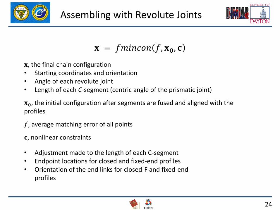
𝐱 = 𝑓𝑚𝑖𝑛𝑐𝑜𝑛 𝑓, 𝐱0, 𝐜
𝐱, the final chain configuration• Starting coordinates and orientation• Angle of each revolute joint• Length of each C-segment (centric angle of the prismatic joint)
𝐱0, the initial configuration after segments are fused and aligned with the profiles
𝑓, average matching error of all points
𝐜, nonlinear constraints
• Adjustment made to the length of each C-segment• Endpoint locations for closed and fixed-end profiles• Orientation of the end links for closed-F and fixed-end
profiles

25
High-Curvature Regions
26
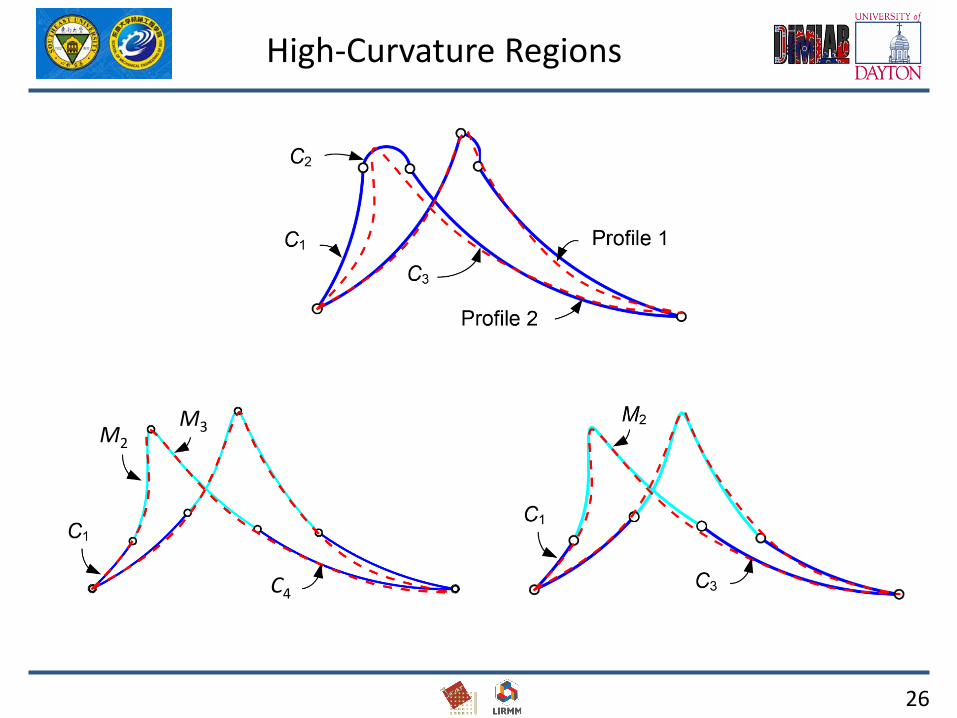
High-Curvature Regions
M2
M3
C4

27
Shifting Endpoints for Closed Profiles
28
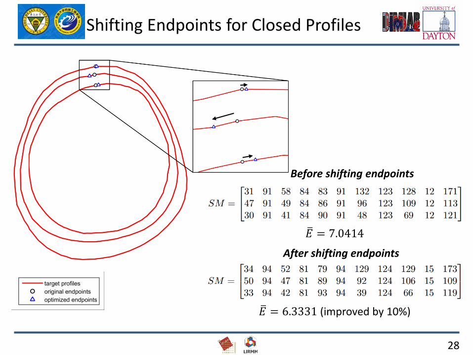
Shifting Endpoints for Closed Profiles
ത𝐸 = 7.0414
ത𝐸 = 6.3331 (improved by 10%)
Before shifting endpoints
After shifting endpoints

29
G-segment
9 segments 12 segments 15 segments

30
Growth Segment Generation
Growth ratio, 𝑟 =𝑚2
𝑚1
Profile 1𝑚1, ҧ𝑠
Profile 2𝑚2, ҧ𝑠
Profile 1’𝑚1, 𝑟 ҧ𝑠
Profile 1’’𝑚2, ҧ𝑠
G-segment 1’
𝑚2, 1
𝑟ҧ𝑠
Arc length: 𝑚1 ҧ𝑠 = 𝑚21
𝑟ҧ𝑠
G-segment 1𝑚1, ҧ𝑠
G-seg 2
Profile 2
Profile 1’’

31
❑Introduction
❑Methodology for planar mechanism design
❑Applications
❑Future work
32
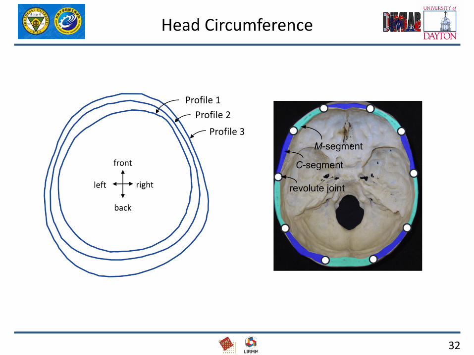
Head Circumference
Profile 1
Profile 2
Profile 3
front
back
left right

33
Head Circumference
Fused connection between endpointsV = [C M C M C M C M C M C]W = [F R F R F F R F R F]10 parameters to characterize shapes (4 R joints & 6 C segments)Max diameter = 877.17, mean matching error = 6.90 (0.79% of max diameter)
C1 C2 C3 C4 C5 C6 R1 R2 R3 R4
Profile1 0.44 0.49 0.38 0.28 0.17 0.46 -0.27 -0.09 -0.08 -0.11
Profile 2 0.96 0.37 0.70 0.16 0.28 0.50 0.21 0.03 -0.05 0.09
Profile 3 0.68 0.73 0.43 0.62 0.46 0.38 0.16 0.26 0.02 0.09

35
The Cochleae
36
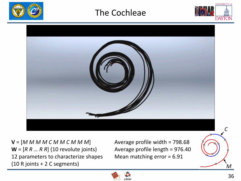
The Cochleae
V = [M M M M C M M C M M M]W = [R R … R R] (10 revolute joints)12 parameters to characterize shapes (10 R joints + 2 C segments)
C
M
Average profile width = 798.68Average profile length = 976.40 Mean matching error = 6.91
37
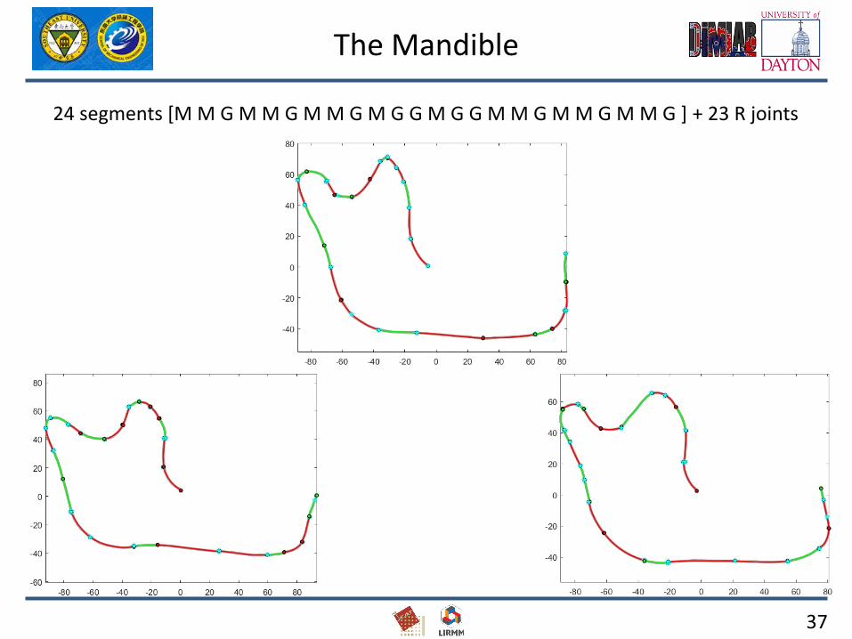
The Mandible
24 segments [M M G M M G M M G M G G M G G M M G M M G M M G ] + 23 R joints

38
The Mandible
33 parameters: 23 R joints + 10 G segments
Discriminant analysis
24 segments [M M G M M G M M G M G G M G G M M G M M G M M G ] + 23 R joints

39
Outline
❑Introduction
❑Methodology for planar mechanism design
❑Applications
❑Future work
40
1. How to define the chain? (segment and connection vectors)
anatomical hypotheses / accuracy.
2. Multivariate analysis of the C segments and the R joints.
Future Work
41
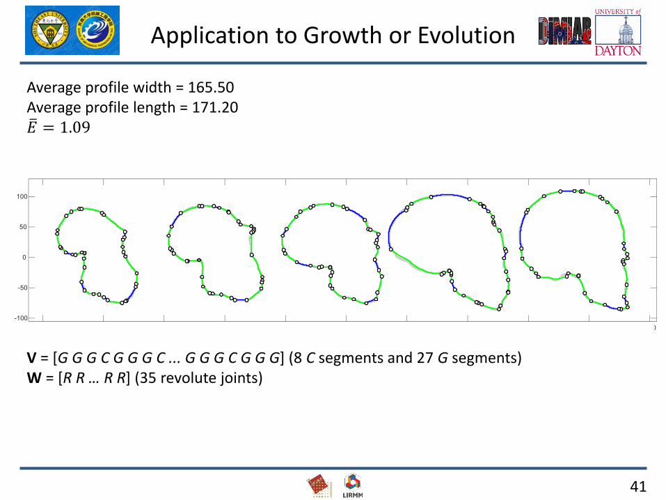
Application to Growth or Evolution
V = [G G G C G G G C ... G G G C G G G] (8 C segments and 27 G segments)W = [R R … R R] (35 revolute joints)
Average profile width = 165.50Average profile length = 171.20ത𝐸 = 1.09

42
Examples: Cochlea in 3D
Generalization to 3D
T= [ M M M M H M H M M] and ball joints

43