29.-the effect of wall-ties on the compressive strength of ... · pdf file178 the elfect of...
TRANSCRIPT

29.-The Effect of Wall-ties on the Compressive Strength of Cavity Walls
by K. FISHER
Redlalld Research &- DeH!lopmenr Lld., GrayJallds, Horsham, Sussex
A BSTRACT
A sllldy has been made of lhe effecI of wall-tie spacing on file compressil'e Jtrength of 11-in. cavity IVal/s of semi-dry pressed bricks, and of perforated bricks. The 1'eflica/fUlis, 'ype oi tie wos used predominall!ly, bur some work IVOS performed with lhe bUlferjfy /ype. Spacings examined were (i) as specified in CP 111: 1964, (ii) dOllble lhe specified nllmber, (iii) lop and baIlam ol1ly. Results are compared wirh [hose obtained for walls containing no lies, and also for 9-in. solid and 4f-in. lValls.
Failure loads are comparedfor walls lVirh load applied lo bOlh lea!'es and la olle lealol7/Y, and are cOl1sidered in re/arioll to lhe brick slrenglh , brickwork cube srrenglh alui lhe permissible design Slresses based on CP 111: 1964. Measllremenls of 100eral dejlecfioll and compressioll llIuler /oad \Vere a/50 recorded.
The reslllls indicale Ihal rhe rype of wall-tie and lhe spacing lias little effecf 011 lhe eompressil1e sfrenglh of lI-in. cal1i1y waI/s. The correlalioll between wall strellglh and brick slrenglh, and between wall strength and brickwork cube sfrenglh ;s good.
The Cllrrenl edi/ioll ofCP 111:1964 appears IIllduly cOI7Sefllalil'e as for as reduclioll faclOrs for flll/y loaded COl'ily \1Ialls are concerned.
1. INTRODUCTION
L'Effet des Entretoises des Murs sur la Résistance à la Compression des Murs Creux Une étude a été faite sur I'effel de I'espacemem des emre/oises sur la résislallce à la compressioll de murs creux de 28 em ell briques pressées par voie semi-hum ide el eu briques perforées. Le Iype d'enlretoise I'ertieale à torsion a été lIf;/isé principalemem, mais quelques essais om é/é réalisés aJ'ee le type "papilon". Les espacements examillés étaiem 1) conformes allx spécificalions CP III (/964), 2) doubles de spécificatiol1s, 3) sommel et base sel/lemem. Les résllltats étaie"t comparés à cel/X obtenus pour des murs ne comportam pas d'enrretoise el également pour des murs pleins de 22·9 em el de 11·45 cm. Les charges de fissura/ioll sonl comparées pour des murs avec des charges appliquées sur les deux faces à la fois el Sllr une face seulemem, el som rapporfées à la résislance de la brique, à la résislallce d'ulI cube de maçoll"erie en brique el aux cOII /rail/tes de conSlruc/ion admissibles basées sur CP 111 (/964). Lesmesllresdedéjormalion lalérale el de compressioll sous charge onl é/é égalemenl enregislrées. Les résulrals monlrelll que le Iype d'emre/oise de mur ell'espacemenln'olJt que peu d' effel sur la résistance à la compressiOfl de murs crel/X de 28 Ctn. La corrélalion entre la résistance du mur el eelle d' 11/1 ellbe de maçonnerie ell briqlle es/ bom/e. L'édi/ion aCluel/emelll ell I'igueur de CP 111 (/964) apparai/ trop prudente en ce qui coneeme les facteurs de réduclioll appliqués al/X murs creux pleinement chargés.
2.1 Brick
Der Einjiufl von Mauerankern aul die Druckfestigkeil von Hoh1wanden
Die Wirkung der Maueral1keranordnllng oI/f die Drl/ckfesligkeit von 28 em dicken Hoh/mauerl1 aus halbtrocken gepresslell Ziegeln und aus Loehziegeln wurde sllidiert. Oberwiegend wurden Anker mil senkrechtem Steg verwendet, tei/weise aber al/ehSchmetter/ing-Anker. Die Anordnllngen IVaren: 1.) wie in der CP 111: 1964 vorgesehen, 2.) die doppelle IVie die l'orgesehene Allzah/ und 3.) nur aben mui unten. Die Ergebnisse sind mil jenen l'ergliehen, die an Wiinden o/me Anker sowie an massiven Wiinden mil 22,9 bzIV. IJ ,45 el1l Dicke gefllnden wurdel1. Die Bruehlasten beiBelasrung beider Seha/en sind mil denen I'erglichen, die sieh bei Belaslwlg nur einerSehale ergaben. Ausserdem sind sieim Verhiiltnis zur Ziegelfestigkeil, der Festigkeit 1'011 Mauerwerkswüfeln sowie dell lIaeh CP 111: 1964 zulassigell Spanmmgen belrachtet. Aueh die Mej3ergebnisse der seitlichen A usbiegung Illld der Slauchung unter A lIjlasr sind allfgezeiehner. Die Resultale zeigen, da'p die Arl wld Allordmmg der Maueranker die Drl/ckfesligkeir 28 cm dicker Hoh/wallde nur wellig beeinflussen. Mauerfesligkeir ",ui Sleinfesligkeir sowie Mal/erfesligkeil und die Fesrigkeit vali Mauerll'erkswürfe/n s/immen gut miteinander überein. Die zur Zeit gellende Ausgabe der CP 111: 1964 sehei,,/ bezügliclz der ReduklionsfaklOren for vali belaslete Hoh/wande übertrieben Ilorsichtig zu sein.
2. MA TERIALS Very little informalion is available on the strength of storey-height cavity walls to justify the view Ihat wallties should be spaced as indicated in CP 111: 1964. ' This paper gives an aceount of direet eompressive and eccentrie loading tests on tied and untied cavity walls.
Two types of brick were used for wall canstruction, a semi-dry pressed brick and a higher strength perforated engineering brick.
The tie spacings examined were (i) as specified in CP 111: 1964; (i i) double the specified number; (iii) top and bottom only. The last was of inlerest in relation to tying of prefabricated brickwork, probably into the floar system. to assess the effeet on lhe tie behaviour under axial and eccentrie loading. Results are compared with those obtained for walIs containing no ties, and solid 9-in. and 4t-in. walls.
177
In the case of the semi-dry pressed brick, walls were constructed of bricks from seven different batches. A sample of ten bricks was taken on receipt of each batch, and at intervals during wall construetion. Crushing strength was determined in accordance with BS 392I.2
The engineering brick used was a twenty-three-hole perforated unit with 21 % perforation. Suflicienl batcbes of bricks were set aside to carry out the envisaged testing programme. A sample of ten bricks was taken aI regular

178 The Elfect of Wall-ties on the Compressive Strength of Cavity Walls intervals throughout the test period, and crushing strength determined in accordance with BS 3921.'
Table 1 summarizes the relevant strength data recorded for the two types of brick.
TABLE l - CRUSHING STR ENGTH OF B RICK SAMPLES
l\If eall Slandard Coeff. B/'jck Sample crushing deviation of varo type No. slrellg/h (Ibfl in Z) (%)
(/bf/in' )
Semi-dry I 4010 758 18·9 pressed 2 4130 543 13 ' 1 brick 3 3680 299 8· 1
4 4290 318 7·4 5 4040 591 14 ·8 6 3480 681 19 ·5 7 3000 395 Jl'2
Perforat- I 9260 1075 11·6 ed 2 9540 1474 15-4 brick 3 9530 I 893 19·9
4 Ii 410 I 114 9·8 5 Ii 680 1425 12 ·2
2.2 Mortar
One source of sand was used for alI the work This was stored in the open and used damp. A typical sieve analysis is given in Table 2.
TABU 2- $IEVE ANALYSIS OF SANO USED
8 .S. Perce11lage siel'e passing size Ihrough
-,\- in. 100 7 97·5
14 91·0 25 73-5 52 27·9
100 4·6
Silt conten! 3%
The lime used conformed to BS 890: 19663 and a 'typical' Portland cement was used throughout.
Mortar for alI walIs was 1:*:3 by volume. For each mix lhe bricklayer was a llowed to add sufficient water to give optimum workability. Ali mortar was lIsed within 2 h of mixing.
Three-inch mortar cubes were cast from each batch of morta r. Arter 24 h lhe cuhes were removed from the moulds to be stored in water until required fo r testing on lhe sal11e day as the corresponding wall. Mortar cube compressive strengths are included in Table 3,
2.3 Wall-ties
Two types of \ValI tie were used conforming to BS 1243: 19644 The vert ical-twist type \Vas used predominantly, but so me experiments were carried out wilh the butterfly type of walI-tie.
3. EXPERIMENTAL DETAILS
3.1 WalI Construction
Walls were constructed and tested on a spreader beam consisting af rolled steel channel infilled with concrete.
TABLE 3-STRENGTH DF SEMI-DRY PRESSED BRICKS, WALLS, MORTAR ANO BRICK CUBES
CompreJsil'e s/rel/g/h (lbflin Z)
Wa/l
Brick I Iype M ortal' Brick Walf cube cube
4t-in. 4010 It80 1930 1830 solid 920 1680 2tJO
I tIO 1970 1790
Means 1070 1860 1920
9-in. 3680 1060 3240 1700 sol id 1i 10 2720 1650
11 30 3070 1600
Means 1100 3010 1650
AI 4010 1060 1450 t870 1190 2760 2030 1010 25 10 t720
Means 1090 2240 1870
A2 4010 970 1180 1870 950 1870 2000
1020 1450 1890
Means 980 1500 1920
81 4130 1060 3320 2250 1370 2970 2020 1040 2590 2350
Means 1160 2960 2210
82 4010 1100 3500 1840 1080 3360 2390 1030 2100 1750
Means 1070 2990 1990
C t 4130 1260 3550 1910 1120 2490 2180 1060 3380 2170
Means 1150 3140 2090
C2 4JlO 980 2940 2280 1060 3300 2280 1050 2950 2030
Means 1030 3060 2200
DI 4010 1000 3120 1740 1090 3860 1790 1270 3670 1840
Means 1120 3550 1790
D2 4010 800 3340 2030 1170 2570 1840 1200 3700 1880
Means 1060 3230 1920
EI 3680 910 2660 1610 990 3530 1730 910 2900 1760
Means 940 3030 1700
E2 3680 870 3630 1820 920 2950 1680 890 3280 1740
Means 890 3290 1750
AlI \Vere 8 ft 3 in. in height (thirty-three courses at four coursesjft) and nominally 4 ft 6 in. in width.
Single-leaf walIs were nominalIy 4±-in. and 9-in. thick , built in stretcher bond and English bond respectively. In cavity waUs, actual cavity width was 2! in. , each leaf being 4k-in. thick.
K. Fisher 179
Bricklaying technique conformed to the requirement of the B. Ceram. R. A. Model Specification.' Wall-ties were built in as work proceeded. Mortar droppings were removed from the cavity. Ali joints were struck ftu sh and pointed as work proceeded. The suction rate of ali semi-dry pressed bricks was adjusted by dipping in water prior to laying. Each wall was capped with a levei t -in. mortar screed on completion of building. In the case of cavity walls where only one leaf was loaded , only that leaf was capped with mortar.
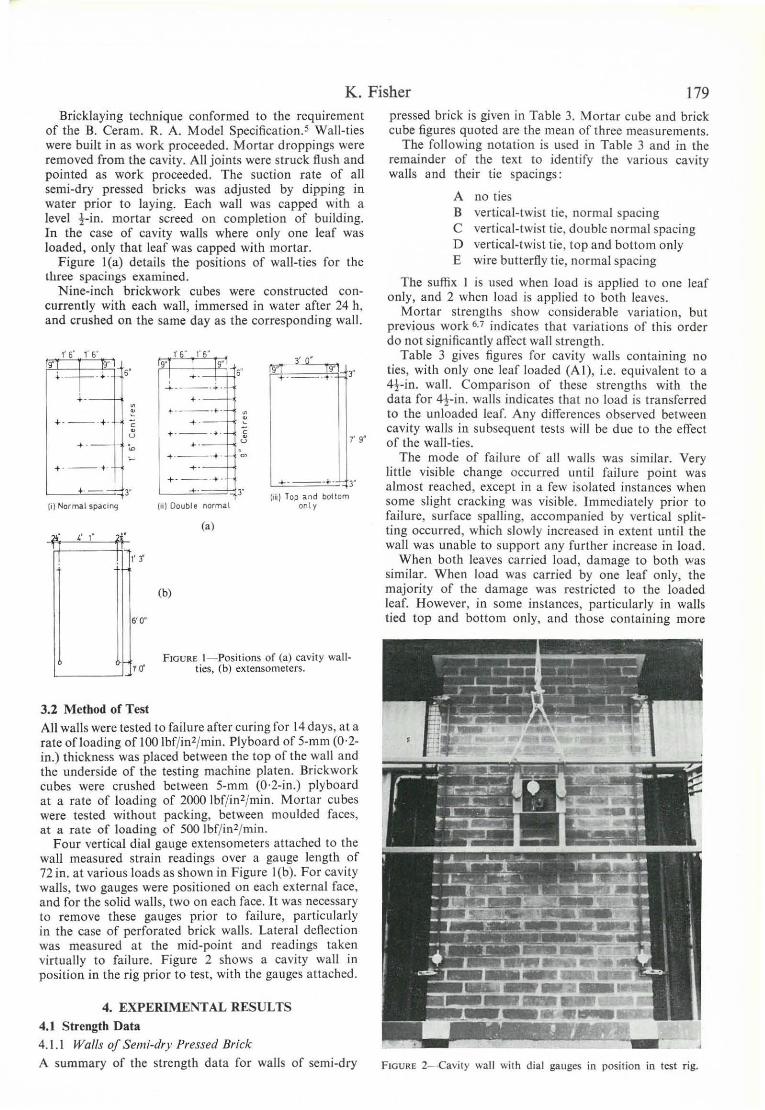
Figure I(a) details the positions of wall-ties for the three spaci ngs examined.
Nine-inch brickwork cubes were constructed COI1-
currently with each wall, immersed in water after 24 h, and crushed on the same day as the corresponding wall.
" 6" f 6' 1'6' "
,. o· q
+i-' ,. ,. 9' ,. +- -+. +-- _ . .j. .
+.- .-· · .--- + . . --_ .. - + - . c · +---.;. ~ v 7' 9' +-- , . v W ~
, ._--.. .~ . ---+ + -
.- ---,- +- ,. •. - ,. .- ,. [iii) Top a nd betlem
li) Normal sp.cing (11) Doublt normal onl y
(al
" I' I " r
(bl
6'0'
FIGURE l- Positions of (a) cav ity wall-L-___ ..J..l1' O' ties, (b) extensometers.
3.2 Method of Test
Ali walls were tested to failure after curing fo r 14 days, at a rate ofloading of 100 Ibf/in2/min. Plyboard of 5-mm (0,2-in.) thickness was placed between the top of the wall and the underside of the testing machine platen. Brickwork cubes were crushed between 5-mm (0·2-in.) plyboard at a rate of loading of 2000 Ibf/ in2/min. Mortar cubes were tested without packing, between moulded faces, at a rate of loading of 500 Ibf/ in2/ min.
Four vertical dial gauge extensometers attached to the wall measured strain readings over a gauge length of 72 in. at various loads as shown in Figure I (b). For cavi ty walls, two gauges were positioned 00 each externai face, and for the solid walls, two on each face. It was necessary to remove these gauges prior to failure , particularly in the case of perforated brick walls. Lateral deftection was measured at the mid-point and readings taken virtually to failure. Figure 2 shows a cavity wall in position in the rig prior to test, with the gauges attached.
4. EXPERIMENTAL RESULTS 4.1 Strength Data
4.1.1 Walls of Semi-dry Pressed Brick
A summary of the st rength data for walls of semi-dry
pressed brick is given in Table 3. Mortar cube and brick cube figures quoted are lhe mean af three rneasurements.
The following notation is used in Table 3 and in the remainder of the text to identify the various cavity walIs and their tie spacings:
A no ties B vertical-twist tie, normal spacing C vertical-twist tie , double normal spacing D vertical-twist tie, top and bottom only E wire butterfty tie, normal spacing
The suffix I is used when load is applied to one leaf only, and 2 when load is applied to both I.aves.
Mortar strengths show considerable variation, but previous work 6,7 indicates lhat variations af this arder do not sign ificantly alfect walI strength.
Table 3 gives figures for cavity walls containing no ties, with only one I.af loaded (A I), i.e. equivalent to a 4!-in. wall. Comparison of these strengths with the data for 4!-in. walls indicates that no load is transferred to the unloaded leaf. Any dilferences observed between cavity walls in subsequent tests will be due to the elfect of the wall-ties.
The mode of failure of ali walls was similar. Very littIe visible change occurred until failure poinl was almast reached, except in a few isolated instances when some slight cracking was visible. lmmediately prior to failure, surface spalling, accompanied by vertical splitting occurred, which slowly increased in extent until the wall was unable to support any further increase in load.
When both leaves carried load, damage to both ",as similar. When load was carried by one leaf only, the majority of the damage was restricted to the loaded tear. However, in some instances, particularly in walls tied top and bottom only, and those containing more
---FIGURE 2- Cavily wall with dial gauges in posi tion in test rig.
180 The Effect of Wall-ties on the Compressive Strength of Cavity Walls than tbe normal tie specification, horizontal cracking occurred along either the bed joint or across the first course (corresponding to a tie position), and in ODe
instance at mid-height corresponding to a tie position. In no case was bending or pulling out of the ties observed.
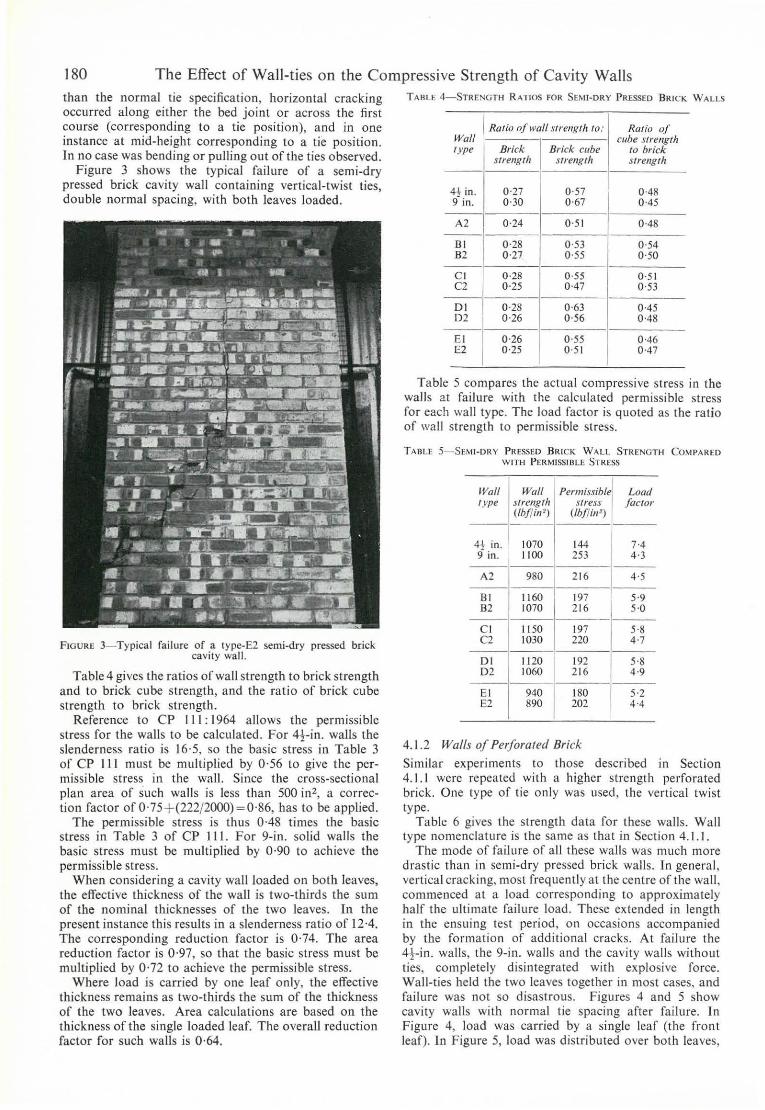
Figure 3 shows the typical failure of a semi-dry pressed brick cavity wall containing vertical-twist ties, double normal spacing, with both leaves loaded.
FIGURE 3-Typical failure of a typc-E2 semi-dry pressed brick cavity wa ll.
Table4 gives the ratios ofwall strength to brick strength and to brick cube strength, and lhe ratio of brick cube strength to brick strength.
Reference to CP 111 : 1964 allows the permissible stress for the walls to be calculated. For 4j--in . walls the slenderness ratio is 16'5, so the basic stress in Table 3 of CP III must be multiplied by 0·56 to give the permissible stress in the wall. Since the cross-sectional plan area of such walls is less than 500 in', a correction factor ofO'75 + (222/2000)=0'86, has to be applied.
The permissible stress is thus 0-48 times the basic stress in Table 3 of CP 111. For 9-in. solid walls the basic stress must be multiplied by 0·90 to achieve the permissible stress.
When considering a cavity wall loaded on both leaves, the effective thickness of the wall is two-Ihird s the sum of the nominal thicknesses of the Iwo leaves. In lhe present instance this results in a slenderness ratio of 12·4. The corresponding reduction facto r is 0·74. The area reduction factor is 0'97, so that the basic stress fiuSt be multiplied by 0·72 to achieve the permissible stress.
Where load is carried by one leaf only, the effective thickness remains as two-thirds the sum of the thickness of the two leaves. Area calculations are based on the thickness of the single loaded leaf. The overall reduction factor for such walls is 0·64.
TARI.E 4- STRENGTH R ATIOS FOR SEMI-DRY PRESSED BRICK WALlS
Rario of \Vali srrellg/h to: R(l/io of Wall cllbe slrengt" Iype Brick Brick cube to brick
slrengrh srrengfh srrenIJ/h
4! in. 0 '27 0·57 0-4R 9 in. 0·30 0·67 0-45
A2 0·24 0 ·5 1 0·48
B1 0·28 0·53 0·54 B2 0 ·2) 0·55 0'50
C I 0·28 0·55 0·51 C2 0·25 0 ·47 0 '53
DI 0·28 0·63 0'45 Dl 0·26 0 ·56 0'48
EI 0·26 0 ·55 0·46 E2 0·25 0 ·5 1 0·47
Table 5 compares the actual compressive stress in the walls at failure wilh the calrulated permissible stress for each \Va li type. The load factor is quoted as the ratio of wall strength to permissible stress.
TABU 5-SEMI-DRY PRESSED BRteK WALL STRENGTH COMPARED WlTH PERMISSlll LE STRESS
IVolI Wall Permissible Loat! /ype slreng /h Slress facror
(lbfl;a' ) (lbJl;a')
4t in. 1070 144 7-4 9 in. 1100 253 4·3
A2 980 216 4 ·5
81 1160 197 5·9 82 1070 216 5·0
C 1 1150 197 5-8 C2 1030 220 4·7
DI 1120
I 192 5·8
D2 1060 216 4·9
E1 940
I 180 5·2
E2 890 202 4 ·4
4.1.2 Walls 01 Perlorated 8rick
Similar experiments to those described in Section 4.1.1 were repeated with a higher strength perforated brick. One type of tie only was used , the vert ical twist type.
Table 6 gives lhe strength data for these walls. Wall type nomenclature is lhe same as that in Section 4.1.1.
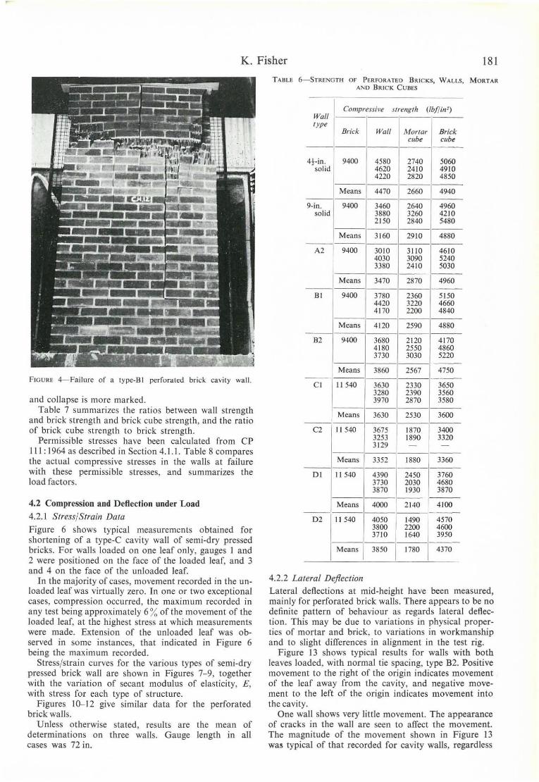
The mo de of failure of ali these walls was much more drastic than in semi-dry pressed brick walls. In general , vertical cracking, most frequently at lhe centre of lhe wall , commenced at a load corresponding to approximately half the ult imate failure load . These extended in length in the ensuing test period , on occasions accompanied by the formation of additional cracks. At failure the 4-r-in . walls , the 9-in. walls and the cavity walls wilhout ties, completely disintegrated with explosive force. Wall-ties held the two leaves together in most cases, and failure was not so disastrous. Figures 4 and 5 show cavity waJls with normal tie spacing after failure. In Figure 4, load was carried by a single leaf (lhe front leaf). [n Figure 5, load was distributed over both leaves,
K. Fisher 181
FIGURE 4-Failure of a typc-BI perforated brick cavity wall.
and collapse is more marked. Table 7 summarizes lhe ratios between wall slrenglh
and brick slrength and brick cube slrenglh, and lhe ratio of brick cube strenglh lo brick strenglh.
Permissible slresses have been calculaled from CP 111: 1964 as described in Section 4.1.1. Table 8 compares the actual compressive stresses in the walls at failure with these permissible stresses, and summarizes lhe load factors.
4.2 Compression and Deflection under Load
4.2.1 Stress/Strain Data
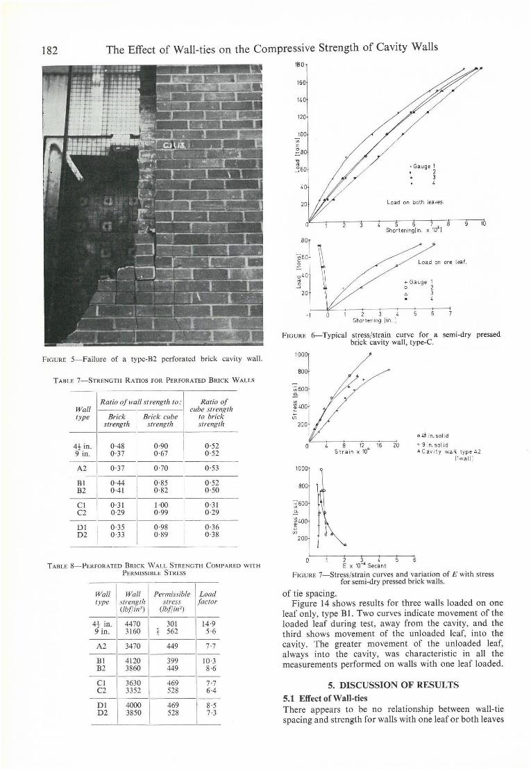
Figure 6 shows typical measuremenls oblained for shortening of a type-C cavity wall of semi-dry pressed bricks. For walls loaded on one !eaf only, gauges I and 2 were positioned on the face of the loaded leaf, and 3 and 4 on the face of lhe unloaded leaf.
In the majority af cases, movement recorded in the unloaded leaf was virtllally zero. In one or two exceptional cases, compression occurred, the maximum recorded in any test being approximalely 6 % of lhe movement of lhe loaded leaf, at the highesl stress at which measurements were made. Extension of the unloaded leaf was observed in some instances, that indicated in Figure 6 being the maximllm recorded.
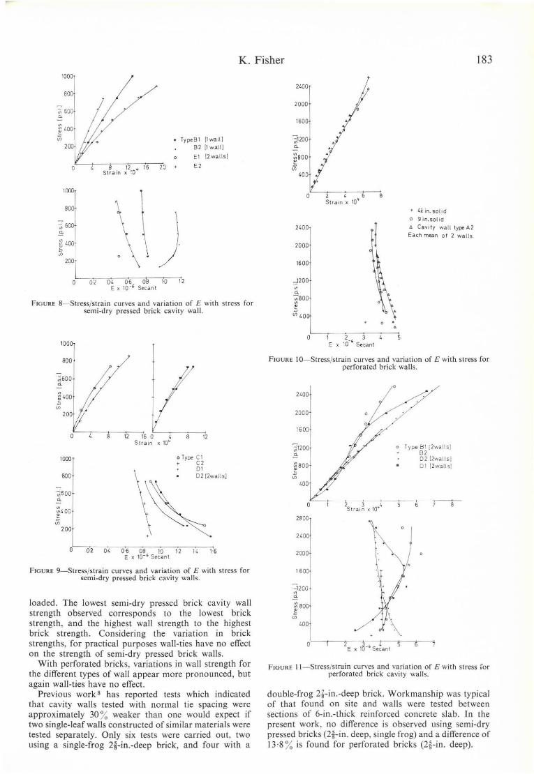
Stress/strain curves for lhe various Iypes of semi-dry pressed brick wall are shown in Figures 7- 9, together with lhe variation af secant modulus af elasticity, E, with stress for each type of structure.
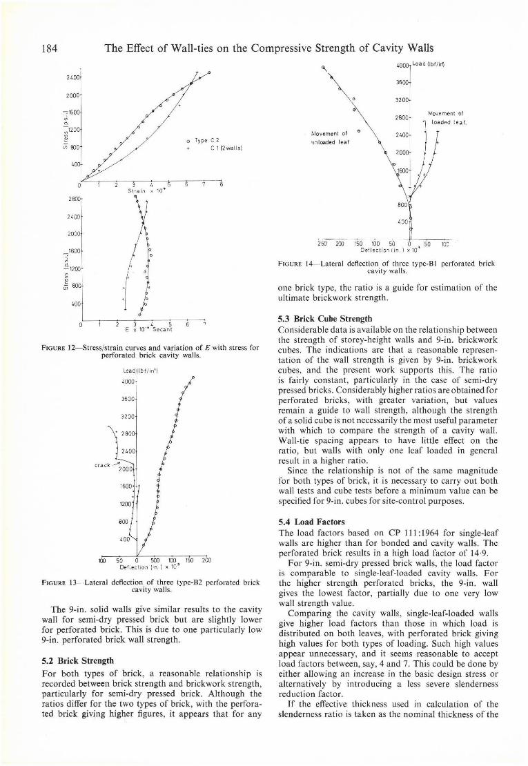
Figures 10-12 give similar data for the perforated brick walls.
Unless otherwise stated, results are lhe mean af determinalions on three walls. Gauge length in ali cases was 72 in.
TABLE 6- STRENGTH OF PERFORATEO BR1CKS, WALLS, MORTAR AND BRICK CUBES
Compressi ve Wall
s frellglh (lbll;"' )
Iype 8rick Wall Morrar Brick
clIbe clIbe
4t·;n. 9400 4580 2740 5060 solid 4620 2410 4910
4220 2820 4850
Means 4470 2660 4940
9-in. 9400 3460 2640 4960 solid 3880 3260 4210
2150 2840 5480
Means 3160 2910 4880
A2 9400 3010 3110 4610 4030 3090 5240 3380 2410 5030
Means 3470 2870 4960
BI 9400 3780 2360 5150 4420 3220 4660 4170 2200 4840
Means 4120 2590 4880
B2 9400 3680 2120 4170 4180 2550 4860 3730 3030 5220
Means 3860 2567 4750
CI 11540 3630 2330 3650 3280 2390 3560 3970 2870 3580
Means 3630 2530 3600
C2 11540 3675 1870 3400 3253 1890 3320 3129 - -
Means 3352 1880 3360
DI I 1540 4390 2450 3760 3730 2030 4680 3870 1930 3870
Means 4000 2140 4100
D2 11540 4050 1490 4570 3800 2200 4600 3710 1640 3950
Means 3850 1780 I 4370
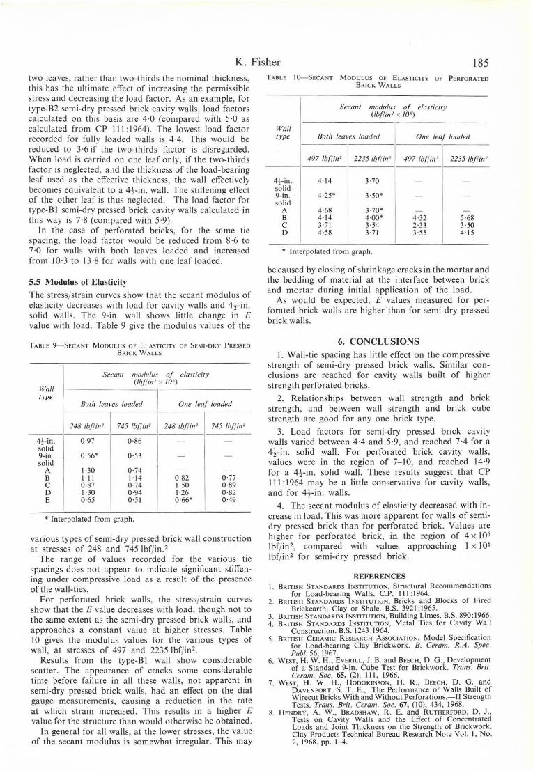
4.2.2 La/eral Deflection Lateral deflections at mid-height have been measured, mainly for perforated brick walls. There appears to be no definite paltem of behaviour as regards lateral deReclion. This may be due to variations in physical properties of mortar and brick, to variations in workmanship and to slight differences in alignment in the test rig.
Figure 13 shows typical results for walls with both leaves loaded, with normal lie spacing, type B2. Positive movement to the right of the origin indicates movement of the leaf away from the cavity, and negative movement to the left of the origin indicates movement into the cavity.
One wall shows very little movemen!. The appearance of cracks in the wall are seen to affec! the movemen!. The magnitude of the movement shown in Figure 13 wa. typical of that recorded for cavity walls, regardless
182 The Effect of Wall-ties on the Compressive Strength of Cavity Walls
FIGURE 5-Faílure of a type-B2 perforated brick cavity wall.
TABLE 7 - STRENGTH RATlOS f OR PERFORATED BRICK WALLS
Rario ofwall strength to: Ratio of Wall cube strength (ype Brick Brick cube lO brick
strength s/rel/g/h slreng fh
4!- in. 0-48 0-90 O-52 9 in. 0 -37 0-67 O-52
A2 0-37 0-70 O-53
BI 0-44 0-85 O- 52 B2 0-41 0-82 O-50
CI 0-31 1-00 0 -3 1 C2 0-29 0-99 0-29
DI 0-35 0 -98 0-36 D2 0-33 0-89 0 -38
TABLE 8 - PERfORATED BRI CK WALL S TRENGTH Cü:\IPARED WITH P ERMISSIB LE STRESS
Wall Wall Permissible Load (ype sfrenglh Sfress factor
(Ib!/ill') (I&!/ill ' )
4t in . 4470 301 14-9 9 in. 3160 ~ 562 5-6
A2 3470 449 7-7
BI 4120 399 10-3 B2 3860 449 8-6
C I 3630 469 7-7 C2 3352 528 6-4
Dl 4000 469 8-5 D2 3850 528 7-3
l~O
160
"O
120
100
80
~60 ~ u'O • .'l
20
U -I O
• Gauge 1 • 2
3 , Load an both leaves
5 6 7 8 Shorteningl in. x lO
l)
9
Load on arte leal .
... Ga uge 1 o 2
3 , " 2 3 4 6
Shortening lin )
10
FIGURE 6- Typical stressfstrain curve for a semi-dry pressed brick cavity wall, type-c.
100~
aool
";;:;60
-"'
o
1000
800
~600 • -"' ~~OO in
200
B. 12,. 16 20 S t r a rn x la
o 2 J ~ 5 6 E )( 10-' Secant
o ti in. so l id
+ 9in.so lid 4. Cavi t y wall. typeA2
jlwa ll!
FIGURE 7-Stress/strain curves and variation of E with stress for semi-dry pressed brick walls.
of tie spacing_ Figure 14 shows results for three walls loaded on one
!eaf only, type BI. Two curves indicate movement of the loaded leaf during test , away from the cavity, and the third shows movement of the unloaded leaf, into the cavity_ The greater movement of the unloaded leaf, always into the cavity, was characteri stic in ali the measurements performed on walls with one leaf loaded_
5. DISCUSSION OF RESULTS
5.1 ElfeelofWall-ties There appears to be no relationship between wall-tie spacing and strength for walls with one leaf ar both leaves
K. Fisher 183 100
'1 80
~ , " ~400 ;;;
200
O . 2
• TypeBl 11wall l 82 11 w aH)
o
8 12" 16 20 Slrain x 10
El !2wa\ls1
E2
\
\ ) O-I. (}6 ------00 lO 12
E x 10 -6 Se<: ant
FIGURE 8- Slress/slrain curves and variation o f E with stress for semi-dry pressed brick cavity wall .
1000
BOa
I ;;i600
" ~ '00
'" 20
0~-;-'--''''2--;\16 O t. 12
1000
aoo
~"oo
"' 200
S lra ln x 10"
oType Cl • ( 2
DI 0 2 r2wa llsl
~. o H ~ H M W U N I~
E x 10- ' Secan!
FIGURE 9- Stress/strain curves and variation of E wilh Slrcss for semi-dry pressed brick cavity wa lls.
loaded. The lowesl semi -dry pressed briek eavity wall strength observed eorresponds to lhe lowest briek strength, and the highest wall strength to the highest briek strength. Considering the variation in briek slrenglhs, for practical purposes wall-ties have no effeel on the strength of semi-dry pressed brick walls.
With perforated bricks, variations in wall strength for lhe different types of wall appear more pronounced, bu! again wall-t ies have no effecl.
Previous work 8 has reported tests which indicated lha! cavity walls tested with normal tie spacing were approximately 30 % weaker than one would expect if two single-leaf walls constructed of similar materiais were tested separately. Only six tests were carried out, two using a single-frog 2i-in.-deep brick, and four with a
21.00
2000
1600
::: 800
" "' '00
0~~2~-;'-~b--:' Slram)C 10~
2400
2000
1600
~200
• ~ ~800
Vi 40
O
o
2_~ 3 E x 10 Secant
5
4i in. so l ld o 9 ln.solld ó Ca vlly waH typtA 2 Each mean o f 2 walls
FIG URE IO- Slressjslrain curves and variation of E with Slress for perforated brick walls .
2LOO
2000
1600
i1200r
~800 1
"' <0O
2900
" O
2000
1600
-:;200 ; ::: 800 • "' <00
o
o Type 9 1 [2wa llsl 62 0 2 12wallsl Dl 12wa lls l
2 3 ~,--s Stra ln x 10 •
o
o
0'--~--~2-E -,-"O -'-s~e~r,-,,~5r-~,--~
FIGUR E II- Stressjstrain curves anel variat ion of E with st ress for perforated brick cavity walls.
double-frog 2i-in.-deep brick. Workmanship was typieal of that found on si te and walls were tested between sections of 6-in.-lhick reinforced concrete slab. In the present work, no difference is observed using semi-dry pressed brieks (2i-in. deep, si ngle frog) and a difference of 13·8 % is found for perforated bricks (2i -in . deep).
184 The E/fect of Wall-ties on the Compressive Strength of Cavity Walls
21;00
2000
::-1600
o TypeC2 C 1 12walls)
o[éV 5 r-s St ra in 10""
2
2400
2000
-;1600
~1200 ~
" .;;SOO
,o o
'j "OlL----,-_-;--c,----;-_T---:~__:;
O E ~ 10-. 4Secan~ 6
FIGURE 12- Stressjstrain curves and variation of E wilh stress for perforated brick cavity walls.
Loa dl(lbf /m' )
4000
3600
3200
• 2800
2400
crack -'" 2000
1600
1200
800
'00
'(() 50 O SOO 100 150 200 Deflection (in. ) x 10 ~
FIGURE 13-LateraJ deflection of three type-B2 perforated brick cavity walls.
The 9-in. solid walls give similar results to the cavity wall for semi-dry pressed brick but are slightly lower for perforated brick. This is due to one particularly low 9-in. perforated brick wall strength.
5.2 Brick Strength
For both types of brick, a reasonable relationship is recorded between brick strength and brickwork strength, particularly for semi-dry pressed brick. Although the ratios dilfer for the two types of brick, wíth the perforated brick giving higher figures , it appears that for any
...
~o ,'.1overnent of
IInloaded leoif
.. •
l.QOO?Load Hbl/iri!
36
3200
2800
800
'00
Movement of
., loaded leaf.
250 >JJ 150 100 _ 50 O .) 50 Deflec tl on I in. ) x 10 IC"
FIGURE 14- Laleral deftection of three type-BI perforated briçk cavity wa!ls.
one brick type, the ratio is a guide for estimatioll of the ultimate brickwork strength.
5.3 Brick Cube Strength Considerable data is available on the relatiol1ship between the strength of storey-height walls and 9-in. brickwork cubes. The indications are that a reasonable representati0l1 of the wall strength is givel1 by 9-in. brickwork cubes, and the present work supports this. The ratio is fairly constant, particularly in the case of semi-dry pressed bricks. Considerably higher ratios areobtained for perforated bricks. with greater variation, but values remain a guide to wall strength, although the strength ofa solid cube is not necessarily the most useful parameter with which to compare the strength of a cavity wall. Wall-tie spacing appears to have little elfect 011 the ratio, but walls with only one leaf loaded in general result in a higher ratio.
Since the relationship is not of the same magnitude for both types of brick, it is necessary to carry out both wall tests and cube tests before a minimum value can be specified for 9-in. cubes for site-control purposes.
5.4 Load Factors The load factors based on CP 111: 1964 for single-Ieaf walls are higher than for bonded and cavity walls. The perforated brick results in a high load facto r of 14·9.
For 9-in. semi-dry pressed brick walls, the load facto r is comparable to single-leaf-Ioaded cavity walls. For the higher strength perforated bricks, the 9-in. wall gives the lowest facto r, partially due to one very low wall strength value.
Comparing the cavity walls, sil1gle-leaf-loaded walls give higher load factors than those in which load is distributed 011 both leaves, with perforated brick giving high values for both types of loading. Such high values appear unnecessary. and it seems reasonable to accept load factors between, say, 4 and 7. This could be dane by either allowing an increase in the basic design stress or alternatively by introducing a less se vere slenderness reduction factor.
If the elfective thickness used in calculation of the slenderness ratio is taken as the nominal thickness of the
K. Fisher 185 two leaves, ralher lhan two-thirds lhe no minal thickness, this has the ultimate effect of increasing the permissible stress and decreasing lhe load fac toT. As ao example, for type-B2 semi-dry pressed brick cavity walls, load factors calculated on thi s basis are 4·0 (compared with 5·0 as caIculated from CP 111 : 1964). The lowest load factor recorded for full y loaded walls is 4·4. This would be reduced to 3·6 if the two- th irds facto r is disregarded . When load is ca rried on a no leaf only, if the two-thirds factor is neglected, and the thickness of the load-bearing leaf used as the effective th ickness, the wall effectively becomes equ ivalent to a 4! -in. wall. The stiffening effect of the other leaf is thus neglected. The load faclOr for type-BI semi-dry pressed brick cavity walls ca1culated in this way is 7·8 (compared with 5·9).
In the case of perforated bricks, for the same tie spacing, the load factor would be reduced fram 8·6 10
7·0 for walls with both leaves loaded and increased from 10·3 to 13 ·8 for walls with one leaf loaded .
5.5 Modulus of Elasticity
The st ressjstrain curves show that the secant modulus of elasticity decreases with load for cavity walls and 41-in. solid wa lls. The 9-in. wall shows little change in E va lue with load. Table 9 give the modulus values of the
TABLE 9-SECANT MODULUS m" ELASTIC ITY QF SE~II -DHY PR ESSl:D BRI C ... W AL LS
Secam /fIodll/tls of e/asticity (/bflil/ 2 X 10⁶ )
Wall Iype
Buril Icaves foaded OI/e leal /oaded
248 Ibflill1 I 745 Ih!li,, ' 248 Ibflill ! 745 Ihfli,, '
4t -in .
I 0·97 0 ·86 - -
solid 9-in. 0 ·56· 0·53 - -solid
A t ·30 0 ·74 - -B 1·11 1·14 0 ·82 0 ·7) C 0·87 0 ·74 1·50 0 ·89 D 1·30 0·94 1·26 0·82 E 0·65 0·5 1 0·66- 0·49
'" ln terpolated from graph .
various types o f semi-dry pressed brick wall construction at stresses of 248 and 745Ibf/in .'
The range of values recorded for the various tie spacings does not appear to indicate significant stiffening under compressive load as a result of thc prcscncc of the wall-ties.
For perforated brick walls, the stress/strain curves show that the E value decreases with load, though not to the same extent as lhe semi-dry pressed brick walls, and approaches a constant value at higher stresses. Table 10 gives the modulus values for the various types of wall , at stresses of 497 and 2235Ibf/in'.
Results from the type-B I wall show considerable scaUer. The appearance of cracks some considerable lime before failure in ali these walls, not apparent in semi-dry pressed brick walls, had an effect on the dial gauge measurements, ca using a reduction in the rate at wh ich strain increased. This results in a higber E value for the structure than wou ld otherwise be obtained.
In general for ali walls, at the lower stresses, the value of the secanl modulus is so mewhat irregular. This may
TABLE 100SECANT MODULUS OF ELASTICITY OF PERFORATED BRICK WALLS
Secam modulus ef elas,icity (lb//int x 106 )
Wa ll 'ype 8 0';' lem'es loaded Olle leal loaded
497 lb/l in 2 1235 Ib/l i,, ! 497 Ibflill ' 1235 Ib/l ill '
4t -in . 4·14 3-70 - -solid 9-in. 4·25· 3·50· - -solid
A 4·68 3·70· - -B 4· 14 4·00· 4·32 5 ·68 C 3·71 3·54 2·33 3·50 D 4·58 3·71 3·55 4·15
• Interpolated from graph .
be caused by closing of shrinkage cracks in the morta r and the bedding of material at the interface between brick and mortar during initial application of the load.
As wou ld be expected, E values measured for perfora ted brick walls are higher than for semi-dry pressed brick walls.
6. CONCLUSIONS I. Wall-tie spacing has little effect 0 0 the compressi"e
strength of semi-dry pressed brick walls. Similar conelusions are reached for cavity walls built of higher strength perforated bricks.
2. Relationships between wall strength and brick strength, and between wall strength and brick cube strength are good for any one brick type.
3. Load factors for semi-dry pressed brick cavity walls varied between 4-4 and 5·9, and reached 7·4 for a 4±-in. solid wall. For perforated brick cavity walls, values were in the region of 7- 10, and reached 14·9 for a 4±-in . solid wall. These results suggest that CP 111 :1964 may be a litt1e conservative for cavity walls, and for 41-in . walls.
4. The secaot modulus of elasticity decreased with increase in load. This was more apparent for walls of semidry pressed brick than for perforated brick. Values are higher for perforaled brick, in the region of 4 x !O" Ibf/in ' , compared with values approaching I x lO" Ibf/in ' for semi-dry pressed brick.
RF.F.F.RENCES 1. BRITISH STANDARDS l NSTITUTlON, Structura[ Recommendat ions
for Load-bearing Walls. c.P. 111 : 1964. 2. BRITISH STANDARDS I NSTITUTION, Bricks and Blocks of Fired
Brickearth, Clay or Shale. B.S. 3921: 1965. 3. BRITISH STANDARDS INSTITUTION, Building Limes. B.S. 890:1966. 4. BRITI SH STANDARDS INSTlTUTION, Metal Ties for Cavity Wall
Construction. B.S. 1243 :1964. 5. BRITISH CERAMIC REsEARCH ÀSSOCIATION, M odel Specification
for Load-bearing Clay Brickwork. 8 . Ceram. R.A. Spee. Puhl. 56. 1967.
6. WEST, H . W. H ., EVERILL, J. B. and BEECH, D. G., Development of a Standard 9-in. Cube Test for Brickwork. Trans . Brit . Ceram. Soe. 65, (2), 111 , 1966.
7. WEST. H . W . H., HODGKI NSON, H. R ., BEECH. D. G. and DAvENPoRT, S. T. E., The Performance of Walls Built of W irecut Bricks With and Without Perforations.-II Strength Tests. TraI/s. Bri, . Ceram. Soe. 67, (10), 434, 1968.
8. HENDRY, A. W ., BRADSHAW, R . E. and RUTHERFORD, D . J., T ests on Cavity W alls and lhe Effec t of Concentrated Loads and Joint Thickness 00 the Strength of Brickwork. Clay Products Technical Bureau Research Note Vol. I , No. 2, 1968. pp . 1-4.