27th high temple workshop 2007 12-15 february 2007, …27th high temple workshop 2007 12-15 february...
TRANSCRIPT

27th HIGH TEMPLE WORKSHOP 2007 12-15 February 2007, Sedona, Arizona
Presentation Title: “High Thermal Conductivity Polymer Matrix Composites (PMC) for Advanced Space Radiators” Authors: E. Eugene Shin1, Cheryl Bowman, Duane Beach, et. al. --- NASA Glenn Research
Center, 21000 Brookpark Rd., Cleveland, OH 44135; 1 Ohio Aerospace Institute Submitted by: E. Eugene Shin
NASA Glenn Research Center - OAI 21000 Brookpark Rd., MS 49-1 Cleveland, Oh 44135 Tel: 216-433-2544, Fax: 216-977-7132 E-mail: [email protected]
Sponsoring Organization: NASA
ABSTRACT High temperature polymer matrix composites (PMC) reinforced with high thermal conductivity (~ 1000 W/mK) pitch-based carbon fibers are evaluated for a facesheet/fin structure of large space radiator systems. Significant weight reductions along with improved thermal performance, structural integrity and space durability toward its metallic counterparts were envisioned. Candidate commercial resin systems including Cyanate Esters, BMIs, and polyimide were selected based on thermal capabilities and processability. PMC laminates were designed to match the thermal expansion coefficient of various metal heat pipes or tubes. Large, but thin composite panels were successfully fabricated after optimizing cure conditions. Space durability of PMC with potential degradation mechanisms was assessed by simulated thermal aging tests in high vacuum, 1-3×10⁻⁶ torr, at three temperatures, 227 °C, 277 °C, and 316 °C for up to one year. Nanocomposites with vapor-grown carbon nano-fibers and exfoliated graphite flakes were attempted to improve thermal conductivity (TC) and micro-cracking resistance. Good quality nanocomposites were fabricated and evaluated for TC and durability including radiation resistance. TC was measured in both in-plan and thru-the-thickness directions, and the effects of microcracks on TC are also being evaluated. This paper will discuss the systematic experimental approaches, various performance-durability evaluations, and current subcomponent design and fabrication/manufacturing efforts. KEY WORDS: High temperature polymer composite, Pitch-based carbon fiber, Facesheet/Fin, Space Radiator, Thermal conductivity, Thermal expansion, Space durability, Nano-composites
https://ntrs.nasa.gov/search.jsp?R=20070010454 2020-01-27T02:15:33+00:00Z

Hig
h T
herm
al C
ondu
ctiv
ity
Pol
ymer
Mat
rix
Com
posi
tes
for
Adv
ance
d S
pace
Rad
iato
rs
E. E
ugen
e Sh
in1 ,
Che
ryl B
owm
an2 ,
Dua
ne B
each
21 O
hio
Aer
ospa
ce In
stitu
te, 2
NA
SA G
lenn
Res
earc
h C
ente
r M
S49-
1 21
000
Bro
okpa
rk R
d., C
leve
land
, OH
441
35;
Tel
: 216
-433
-254
4, F
ax: 2
16-9
77-7
132
E-m
ail:
Euy
-Sik
.E.S
hin@
nasa
.gov
27th
Hig
h Te
mpl
e W
orks
hop
Febr
uary
12
-15,
200
7Se
dona
, Ariz
ona
Spon
sore
d by
NAS
A Pr
omet
heus
pro
gram
and
Adv
Spa
ce T
echn
olog
y pr
ogra
m u
nder
Ex
plor
atio
n Sy
stem
s M
issi
on
E. E
ugen
e Sh
in, 2
7th
Hig
h T
empl
e W
orks
hop
Feb
12-1
5, 0
72
Con
trib
utor
sJa
ne M
ande
rsch
eid,
GRC:
Rad
iato
r su
b-pa
nel d
esig
nD
erek
Qua
de, G
RC:
PMC
pane
l & r
adia
tor
sub-
pane
l fab
ricat
ion
Dav
e Ko
wal
ski,
GRC:
PMC
vacu
um T
herm
al a
ging
Mic
helle
Cyb
ulsk
i, U
.of
Day
ton-
sum
mer
inte
rnD
an S
chei
man
, ASR
C/G
RC:
PMC
ther
mal
pro
pert
ies;
Vac
. The
rmal
agi
ngRoh
itM
ital,
OSU
-sum
mer
inte
rn:
PM
C th
erm
al c
ondu
ctiv
ity &
Im
age
anal
ysis
Ric
hard
Mar
tin, C
SU/G
RC:
IR
The
rmog
raph
y N
DE
of r
adia
tor
sub-
pane
lsD
emet
rios
Papa
dopo
ulos
, U. o
f Ak
ron/
GRC:
P
MC
mec
hani
cal p
rope
rtie
sLi
nda
McC
orkl
e, O
AI/G
RC:
PMC
SEM
Mic
rogr
aphs
; th
erm
al c
ondu
ctiv
ityLi
nda
Ingh
ram
, OAI
/GRC:
P
MC
ND
E &
aci
d di
gest
ion
Chris
Bur
ke, A
SRC/
GRC:
The
rmal
cyc
ling
test
of
radi
ator
sub
-pan
els
Don
Jaw
orsk
e, G
RC:
R
adia
tion
test
ing
Tim
Ubi
ensk
i, Jo
e La
velle
, SLI
/GRC:
PMC
mac
hini
ng &
tes
t fix
ture
fab
ricat
ion
Sang
woo
k Si
hn, U
DRI-
AF:
PM
C pa
nel l
amin
atio
n la
y-up
ana
lysi
s Pa
ul B
iney
, Pra
irie
View
A&
M U
.:
The
rmal
spi
king
exp
erim
ent
UD
RI
and
Nan
ospe
rse,
MRI:
Nan
o fo
rmul
atio
n an
d co
mpo
undi
ngYL
A, I
nc.:
PM
C pr
epre
ggin
gCa
nyon
com
posi
tes:
PMC
pane
l fab
ricat
ion

E. E
ugen
e Sh
in, 2
7th
Hig
h T
empl
e W
orks
hop
Feb
12-1
5, 0
73
Sub
ject
Mat
ter
Back
grou
ndPM
C Rad
iato
r Pa
nel D
esig
n &
Mat
eria
l Sel
ectio
nPM
C Fa
cesh
eet
Des
ign
and
Fabr
icat
ion
PMC
Perf
orm
ance
& F
easi
bilit
y Ev
alua
tion
Ther
mal
con
duct
ivity
and
Nan
o-co
mpo
site
sEf
fect
s of
mic
ro-c
rack
sVa
cuum
the
rmal
agi
ngRa
diat
ion
hard
ness
PMC
Rad
iato
r Su
b-Pa
nel F
abric
atio
nO
verw
rap
co-c
ure
vs. 2
ndar
y bo
ndin
gTh
erm
al p
erfo
rman
ceH
T-PM
C bo
ndin
g ev
alua
tion
Sum
mar
y an
d Fu
ture
wor
k pl
an
E. E
ugen
e Sh
in, 2
7th
Hig
h T
empl
e W
orks
hop
Feb
12-1
5, 0
74
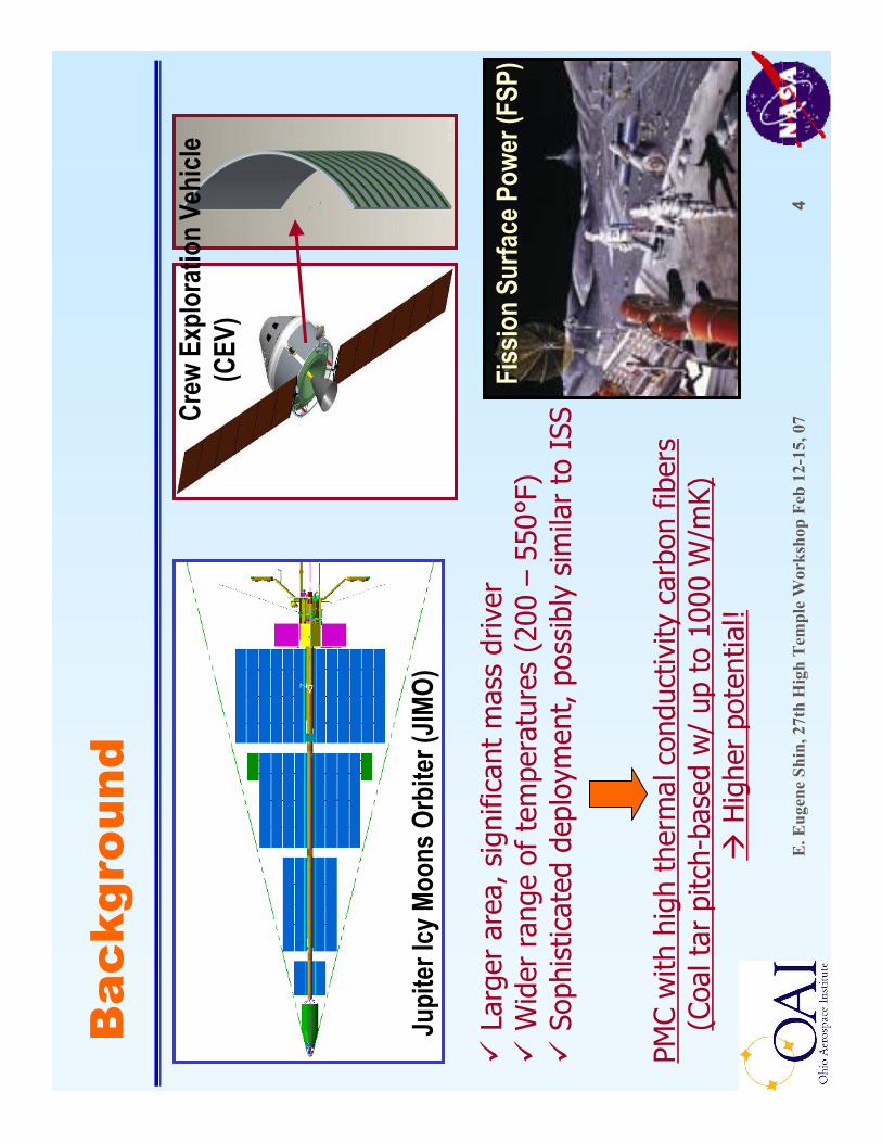
Bac
kgro
und
Jupi
ter I
cy M
oons
Orb
iter (
JIMO)
Crew
Exp
lora
tion
Vehi
cle
(CEV
)
Larg
er a
rea,
sig
nific
ant
mas
s dr
iver
Wid
er r
ange
of
tem
pera
ture
s (2
00 –
550°
F)So
phis
ticat
ed d
eplo
ymen
t, p
ossi
bly
sim
ilar
to I
SS
PMC
with
hig
h th
erm
al c
ondu
ctiv
ity c
arbo
n fib
ers
(Coa
l tar
pitc
h-ba
sed
w/
up t
o 10
00 W
/mK)
H
ighe
r po
tent
ial!
Fiss
ion
Surfa
ce P
ower
(FSP
)

E. E
ugen
e Sh
in, 2
7th
Hig
h T
empl
e W
orks
hop
Feb
12-1
5, 0
75
Pol
ymer
Mat
rix
Com
posi
tes
RO
M P
RO
PER
TIES
RO
M P
RO
PER
TIES
(+)
Hig
h s
peci
fic
stif
fnes
s &
str
engt
h(+
) Le
ast
expe
nsi
ve c
ompo
site
for
m(+
) Ta
ilora
ble
CTE
, th
erm
al c
ondu
ctiv
ity,
m
ech
anic
al p
rope
rtie
s(+
) Es
tabl
ish
ed m
anu
fact
uri
ng
base
(-)
Du
rabi
lity
insu
ffic
ien
tly
char
acte
rize
d(-
) P
oor
thru
-th
ickn
ess
T co
ndu
ctiv
ity
(-)
Hig
hly
an
isot
ropi
c pr
oper
ties
(-
) B
ondi
ng
chal
len
ges
w/
met
al H
P/H
T
1.8
1.8
1.8
RT
Den
sity
(g
/cm
3)
--~1
~4
0
Tran
s.
--1
.2C
TE (μm
/mK
)
400
590
Mod
ulu
s (G
Pa)
1.3
2St
ren
gth
(G
Pa)
300
600
RT
Con
duct
ivit
y (W
/mK
)
0°±
30°
Axi
alK
11
00
/pol
ymer
K1
10
0/p
olym
er6
0%
Fib
er V
ol6
0%
Fib
er V
ol
PRO
S A
ND
CO
NS
PRO
S A
ND
CO
NS
DES
CR
IPTI
ON
DES
CR
IPTI
ON
Varie
ties o
f mat
erial
choi
ces;
fibe
rs, r
esin
sCo
mm
only
used
for s
pace
craf
t stru
ctur
al m
embe
rs an
d lo
wer t
empe
ratu
re ra
diat
ors
Inhe
rent
ly lo
w re
sin th
erm
al co
nduc
tivity
; bu
t im
prov
ed b
y the
use
of n
ano-
filler
s tra
nsfe
rabl
e to
cont
inuo
us fi
ber P
MCs?
Res
in G
lass
Tra
nsiti
on T
empe
ratu
res
Res
in G
lass
Tra
nsiti
on T
empe
ratu
res
Toug
hene
d Ep
oxy
Toug
hene
d Ep
oxy
Cyan
ate
Cyan
ate
Este
rEs
ter
BMI
BMI
BMI
BMI
Poly
imid
ePo
lyim
ide Poly
imid
ePo
lyim
ide
300
350
400
450
500
550
600
650
Temp (K)
E. E
ugen
e Sh
in, 2
7th
Hig
h T
empl
e W
orks
hop
Feb
12-1
5, 0
76
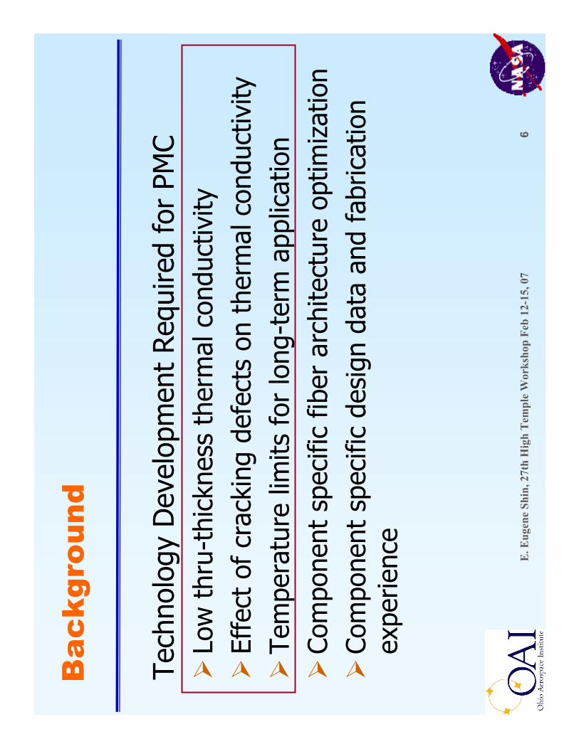
Bac
kgro
und
Tech
nolo
gy D
evel
opm
ent
Req
uire
d fo
r PM
CLo
w t
hru-
thic
knes
s th
erm
al c
ondu
ctiv
ityEf
fect
of
crac
king
def
ects
on
ther
mal
con
duct
ivity
Tem
pera
ture
lim
its f
or lo
ng-t
erm
app
licat
ion
Com
pone
nt s
peci
fic f
iber
arc
hite
ctur
e op
timiz
atio
nCo
mpo
nent
spe
cific
des
ign
data
and
fab
ricat
ion
expe
rienc
e

E. E
ugen
e Sh
in, 2
7th
Hig
h T
empl
e W
orks
hop
Feb
12-1
5, 0
77
PM
C R
adia
tor
Pan
el D
esig
ns PMC
mat
eria
lH
T m
ater
ial;
Al,
SS, T
iH
T ra
dius
PMC
f/s
Thic
knes
sA
dhes
ive
mat
eria
l
Sand
wich
Over
wrap
Bond
ed
PMC
mat
eria
lSa
ddle
mat
rl&
des
ign
Adh
esiv
e m
ater
ial
Cor
e m
ater
ial &
type
Varia
bles
PMC
mat
eria
lH
T m
ater
ials
; Al,
SS, T
iA
dhes
ive
mat
eria
lA
dhes
ive
thic
knes
s
Bal
ance
of
ther
mal
per
form
ance
an
d st
ruct
ura
l in
tegr
ity
E. E
ugen
e Sh
in, 2
7th
Hig
h T
empl
e W
orks
hop
Feb
12-1
5, 0
78
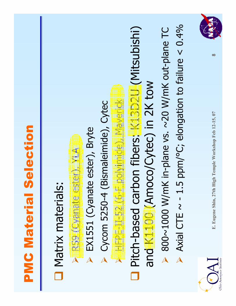
PM
C M
ater
ial S
elec
tion
Mat
rix m
ater
ials
:RS9
(Cy
anat
ees
ter)
, YLA
EX15
51 (
Cyan
ate
este
r), B
ryte
Cyco
m52
50-4
(Bi
smal
eim
ide)
, Cyt
ec
HFP
E-II
-52
(6-F
pol
yim
ide)
, Mav
eric
k
Pitc
h-ba
sed
carb
on f
iber
s: K
13D
2U (
Mits
ubis
hi)
and
K110
0 (A
moc
o/Cy
tec)
in 2
K to
w80
0~10
00 W
/mK
in-p
lane
vs.
~20
W/m
Kou
t-pl
ane
TC
Axia
l CTE
~ -
1.5
ppm
/°C;
elo
ngat
ion
to f
ailu
re <
0.4
%

E. E
ugen
e Sh
in, 2
7th
Hig
h T
empl
e W
orks
hop
Feb
12-1
5, 0
79
PM
C F
aces
heet
Des
ign
–C
TE
mat
chin
g
PMC
f/s
lay-
up c
onfig
urat
ions
to
mat
ch C
TE o
f m
etal
HP/
HT
via
vario
us
anal
ytic
al s
olut
ions
bas
ed o
n la
min
atio
n th
eory
: [
0/15
/-15
] nfo
r al
umin
um
vs. [
0/25
/-25
] nfo
r st
ainl
ess
stee
l vs.
[0/
30/-
30] n
for
Tita
nium
-505101520253035
010
2030
4050
6070
80
Angl
e of
Off
Axis
Plie
s, α
90° CTE of PMC Laminate, ppm/°C
53%
FV, E
2=5G
Pa; U
DRI
53%
FV, E
2=12
GP
a; U
DRI
60%
FV, E
2=5G
Pa; U
DRI
60%
FV, E
2=9G
Pa; G
RC-
ICAN
60%
FV, E
2=12
GP
a; U
DRI
60%
FV, E
2=?;
ATK
53%
FV, E
2=?;
ATK
Hea
t Pip
e A
xis
= 90
°
10.9
5.7
12.7
19.3
10
5.4
15.8
9.9
11.4
17.1
5101520
2324
2526
2728
2930
3132
CTE
of H
P/H
TTi
=
~ 9
ppm
/°CSS
= ~
16 p
pm/°C
Al
= ~
24 p
pm/°C
Lay-
up C
onfig
urat
ion:
[0, +
α, -α
] 1S
HFP
E/K
1100
50%
FVF
RS9
D/K
1100
56%
FVF

E. E
ugen
e Sh
in, 2
7th
Hig
h T
empl
e W
orks
hop
Feb
12-1
5, 0
710
PM
C F
aces
heet
Fab
rica
tion
Hot
-mel
t pr
epre
ggin
g (Y
LA);
12
”w
ide,
37w
% r
esin
, 67
gsm
FAW
0.
0025
inch
thi
ck a
fter
cur
e, 6
0 v%
FVF
tar
gete
d
Pane
l fab
(GRC
or C
anyo
n);
Han
d la
y-up
(12
”x12
”or
24”
x36”
or 3
6”x4
4”;
6-pl
y)
optim
ized
vac
uum
bag
ging
auto
clav
e cu
rew
/
C-sc
an a
nd Q
C te
stin
g (G
RC)
RS-
9D c
ure
Appl
y 28
in/H
g va
c&
80
psi P
Hea
t to
390
°F
@ 3
–5
°F/m
inH
old
at 3
90 °
F fo
r 12
7 m
inCo
ol t
o RT
@ ~
3°F
/min
Post
cure
at
600
°F f
or 4
hrs
fr
ee s
tand
ing
in a
ir
HFP
E-II
-52
cure
B-st
agin
g @
400
ºF f
or 1
hr
Post
cure
@ 7
00°F
for
16
hrs
in a
ir
0
10
0
20
0
30
0
40
0
01
20
24
03
60
48
06
00
72
08
40
96
0
Part Pressure, psi / Vacuum, inHg
Vacu
um
44
0m
in
65m
in
20
0m
in
0
10
0
20
0
30
0
40
0
50
0
60
0
70
0
80
0
01
20
24
03
60
48
06
00
72
08
40
96
0T
ime
, m
in
Part Temperature, ºF
14
0m
in
1.0
ºF/m
in
5.0
ºF/m
in
2.9
ºF/m
in
60
min
110
min
70m
in55
min
5.0
ºF/m
in

E. E
ugen
e Sh
in, 2
7th
Hig
h T
empl
e W
orks
hop
Feb
12-1
5, 0
711
The
rmal
con
duct
ivit
y an
d N
ano-
com
posi
tes
-Mat
eria
l Sel
ecti
ons
Hig
h th
erm
al c
ondu
ctiv
ity n
ano
fille
rs s
tudi
ed;
Vapo
r gr
own
carb
on n
ano
fiber
s (V
GCN
F)--
-hi
gh
tem
pera
ture
gra
de:
PR24
HH
T, A
SIde
nsity
= ~
1.8
g/cc
, a t
ube
stru
ctur
e of
gra
phite
w/
varia
ble
mor
phol
ogy
and
dens
ities
Aver
age
diam
eter
= ~
100
nm (
10 n
m -
500
nm in
di
strib
utio
n), a
spec
t ra
tio =
~50
0
Exfo
liate
d gr
aphi
te f
lake
s (E
xGf)
---
exfo
liate
d by
UD
RI
pate
nted
pro
cess
RS-
9D C
yana
tees
ter
resi
n (Y
LA)
+ K
13D
2U C
-fib
er
(Mits
ubis
hi)
com
posi
te s
yste
m
E. E
ugen
e Sh
in, 2
7th
Hig
h T
empl
e W
orks
hop
Feb
12-1
5, 0
712
130º
F
Dia
mon
d Po
lyU
nwin
d 4
Top
Pap
erT
ake-
up 2
Top
Pap
er L
et-O
ffU
nwin
d 3
Fabr
ic L
et-O
ffU
nwin
d 2
Bot
tom
Pap
erLe
t-Off
Unw
ind
1
Nip
s
Idle
rs
Idle
rs
Idle
r
Rub
ber
Rol
lSl
itter
s
Prod
uct
Win
d-up
Chill
Plat
eHo
t Plat
e
Hig
h C
onc.
PM
R-I
I-50
Mon
omer
Sol
utio
n (~
80%
)
64"
Rem
oval
of E
xces
s So
lven
t @ h
igh
Vac
uum
, ~12
0ºF
Roo
m te
mp.
Res
in a
mou
nt in
pre
preg
co
ntro
lled
by•g
ap b
etwe
en n
ip r
olle
rs•r
olle
r te
mpe
ratu
re•r
olle
r rp
m
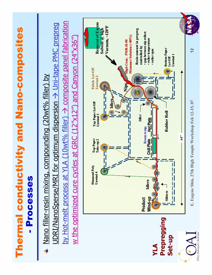
Nan
o fil
ler-
resi
n m
ixin
g, c
ompo
undi
ng (
20w
t% f
iller
) by
U
DRI/
Nan
oSpe
rse/
MRI
for
optim
um d
ispe
rsio
nU
ni-t
ape
PMC
prep
reg
by H
ot-m
elt
proc
ess
at Y
LA (
10w
t% f
iller
) co
mpo
site
pan
el f
abric
atio
n w
the
opt
imiz
ed c
ure
cycl
es a
t G
RC
(12”
x12”
) an
d Ca
nyon
(24
”x36
”)
YLA
P
repr
eggi
ng
Set-
up
The
rmal
con
duct
ivit
y an
d N
ano-
com
posi
tes
-Pro
cess
es

E. E
ugen
e Sh
in, 2
7th
Hig
h T
empl
e W
orks
hop
Feb
12-1
5, 0
713
The
rmal
con
duct
ivit
y an
d N
ano-
com
posi
tes
-Pre
limin
ary
Res
ults
12-p
ly, [
0/+
30/-
30/-
30/+
30/0
] 1S
to m
atch
CTE
of
Ti h
eat
pipe
(H
P);
12”x
12”x
0.02
8”
Cure
d @
380
°F,
80p
si, 2
8 in
/Hg
vacu
um f
or 2
hrs
w/
optim
ized
bag
ging
Po
stcu
red
at 6
00 °
F fo
r 4
hour
s
C-sc
an N
DE
Stra
ight
resin
Resin
+ V
GCNF
(10w
t%)
Resin
+ VG
CNF
(5wt
%)
+ Ex
Gf(5
wt%
)
E. E
ugen
e Sh
in, 2
7th
Hig
h T
empl
e W
orks
hop
Feb
12-1
5, 0
714
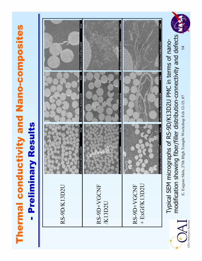
RS-
9D+V
GC
NF
/K13
D2U
RS-
9D/K
13D
2U
RS-
9D+V
GC
NF
+ Ex
Gf/K
13D
2U
Typi
cal S
EM m
icro
grap
hs o
f RS-
9D/K
13D
2U P
MC
in t
erm
s of
nan
o-m
odifi
catio
n sh
owin
g fib
er/f
iller
dis
trib
utio
n-co
nnec
tivity
and
def
ects
The
rmal
con
duct
ivit
y an
d N
ano-
com
posi
tes
-Pre
limin
ary
Res
ults

E. E
ugen
e Sh
in, 2
7th
Hig
h T
empl
e W
orks
hop
Feb
12-1
5, 0
715
410
423
368
57.3
Stra
ight
resi
n
410
413
330
46.0
Res
in+V
GC
NF+
ExG
f40
841
130
954
.2R
esin
+VG
CN
F
Tan δ
G' o
nset
Td, °
C
(TG
A in
N2)
Tg, °
C (b
y D
MA
)F.
V.F
*, %
Pro
perti
esP
MC
Lam
inat
e ty
pe
* F.
V.F
was
det
erm
ined
by
optic
al im
age
anal
ysis
in K
eyen
ce h
igh
pow
er (
500x
) di
gita
l mic
rosc
ope
syst
em (
Not
e: n
ano
fille
r vo
lum
e co
unte
d in
res
in v
olum
e)
The
rmal
con
duct
ivit
y an
d N
ano-
com
posi
tes
-Pre
limin
ary
Res
ults

E. E
ugen
e Sh
in, 2
7th
Hig
h T
empl
e W
orks
hop
Feb
12-1
5, 0
716
METZ
SCH
LFA
447 1.44
1.37
1.42
0.62
0.78
1.00
Z-di
r.47
5159
2029
4290
°20
624
029
988
138
212
1.34
1.00
0.81
1.75
0°
1.47
1.43
1.30
0.66
0.86
1.09
Z-di
r.37
4223
3590
°16
618
019
874
108
166
1.32
0.98
0.70
1.70
0°RS-
9D+V
GC
NF+
ExG
f/K13
D2U
lam
inat
e1.
511.
461.
360.
610.
791.
01Z-
dir.
4550
5618
2742
90°
213
223
241
8612
117
91.
451.
080.
791.
720°R
S-9D
+VG
CN
F/K
13D
2U la
min
ate
RS-
9D S
trai
ght/K
13D
2U la
min
ate
300 °
C15
0 °C
20 °C
300 °
C15
0 °C
20 °C
300 °
C15
0 °C
20 °C
g/cc
Cond
uctiv
ity, W
/mK
Diffu
sivity
, mm
2 /sec
Spec
ific h
eat c
apac
ity, J
/g °C
Dens
ity
* Th
erm
al d
iffus
ivity
by
Lase
r Fl
ash
Anal
ysis
(LF
A 44
7), Δ
Cp b
y m
DSC
, den
sity
by
dim
.
The
rmal
con
duct
ivit
y an
d N
ano-
com
posi
tes
-Pre
limin
ary
Res
ults

E. E
ugen
e Sh
in, 2
7th
Hig
h T
empl
e W
orks
hop
Feb
12-1
5, 0
717
1.47
1.43
1.30
0.66
0.86
1.09
1.32
0.98
0.70
1.70
RS-
9D+V
GC
NF+
ExG
f/K13
D2U
lam
inat
e
Z-di
r.
1.44
1.37
1.42
0.62
0.78
1.00
Z-di
r.1.
341.
000.
811.
75
2.08
1.90
2.28
1.16
1.44
1.98
Z-di
r.1.
330.
980.
861.
34
HFP
E-II-
52 P
olyi
mid
e/K
13D
2U la
mia
nte
1.51
1.46
1.36
0.61
0.79
1.01
Z-di
r.1.
451.
080.
791.
72R
S-9D
+VG
CN
F/K
13D
2U la
min
ate
RS-
9D S
trai
ght/K
13D
2U la
min
ate
300 °
C15
0 °C
20 °C
300 °
C15
0 °C
20 °C
300 °
C15
0 °C
20 °C
g/cc
Cond
uctiv
ity, W
/mK
Diffu
sivity
, mm
2 /sec
Spec
ific h
eat c
apac
ity, J
/g °C
Dens
ity
The
rmal
con
duct
ivit
y an
d N
ano-
com
posi
tes
-Pre
limin
ary
Res
ults

E. E
ugen
e Sh
in, 2
7th
Hig
h T
empl
e W
orks
hop
Feb
12-1
5, 0
718
Eff
ects
of
Mic
rocr
acks
-Pre
limin
ary
Res
ults
Ther
mal
spi
king
pre
cond
ition
ing
expe
rimen
ts (
Prai
rie V
iew
A&
M f
acili
ty)
RS-9
D/K
13D
2U:
[0/
30/-
30]1
s vs
[0/3
0/-3
0/-3
0/30
/0]1
s vs
[0/6
0/-6
0/-6
0/60
/0]2
s LN
2⇔
177
°C (
350°
F)D
ensi
ty o
f m
icro
crac
k
mea
sure
d, #
/mm
TC m
easu
rem
ents
in t
hru-
thic
knes
s di
rect
ion,
W/m
K
Obj
ecti
ve:
Det
erm
ine
effe
cts
of m
icro
crac
ks o
n t
her
mal
con
duct
ivit
y
1.93
7±0.
071.
975±
0.13
12-p
ly1.
404±
0.02
1.73
9±0.
1924
-ply
1250
cyc
les
0 cy
cle
7.0±
0.5
7.6±
1.9
6.9±
1.2
4.4±
1.7
24-p
ly6.
1±1.
45.
0±1.
43.
0±1.
812
-ply
1250
cyc
les
950
cycl
es75
0 cy
cles
450
cycl
es

E. E
ugen
e Sh
in, 2
7th
Hig
h T
empl
e W
orks
hop
Feb
12-1
5, 0
719
Eff
ects
of
Mic
rocr
acks
-Cur
rent
Wor
k P
lan
RS-
9D/K
13D
2U v
s. R
S-9X
1 (V
GCN
F-PR
24H
HT)
/K13
D2U
vs
. RS-
9X2
(VG
CNF+
ExG
f)/K
13D
2U
Also
, eff
ects
of
nano
-mod
ifica
tion
on m
icro
crac
king
All 1
2-pl
y [0
/30/
-30/
-30/
30/0
]1s
Ther
mal
spi
king
pre
cond
ition
ing
expe
rimen
ts
(Pra
irie
View
A&
M f
acili
ty)
LN2 ⇔
up t
o 23
2 °C
(45
0°F)
, aut
omat
ed c
ycle
@ 4
cy
cles
/hr
up t
o 2,
000
cycl
es
TC m
easu
rem
ents
: 0
°an
d 90
°in
-pla
ne d
irect
ions
vs.
th
ru-t
hick
ness
dire
ctio
n

E. E
ugen
e Sh
in, 2
7th
Hig
h T
empl
e W
orks
hop
Feb
12-1
5, 0
720
To a
sses
s PM
C sp
ace
dura
bilit
y by
the
acc
eler
ated
the
rmal
ag
ing
unde
r hi
gh v
acuu
m in
sim
ulat
ing
spac
e en
viro
nmen
tsTo
dow
n-se
lect
mos
t du
rabl
e PM
C ca
ndid
ate
syst
emTo
iden
tify
PMC
degr
adat
ion
mod
es a
nd m
echa
nism
s
232
-28
8~
349
C: R
S-9D
/K13
D2U
~ 3
1640
4B:
HFP
E/K1
100
~ 3
1639
0A:
HFP
E/K1
3D2U
>28
8~
371
F: R
S-9X
2 (V
GCN
F+Ex
Gf)
/K13
D2U
>28
8~
366
E: R
S-9X
1 (V
GCN
F)/K
13D
2U
232
-28
836
1D
: RS-
9D/K
1100
Max
. use
T, °
CD
ry T
g, °
CP
MC
Can
dida
tes
Vac
uum
The
rmal
Agi
ng
All
test
pan
els:
6-p
ly [0
, +30
, -30
] 1S

E. E
ugen
e Sh
in, 2
7th
Hig
h T
empl
e W
orks
hop
Feb
12-1
5, 0
721
Vac
uum
The
rmal
Agi
ng-E
xper
imen
tal s
et-u
p
22
7 v
s 2
77
vs
31
6°C
(4
40
vs
53
1 v
s6
00
°F)
10
-6to
rrU
p to
10
,00
0 h
rs -
--0
; 5
0;
15
0;
25
0;
41
7 d
ays
Tota
l 4
8 3
"x3
"; 1
8 6
"x4
"; 1
8 4
"x6
" ar
ran
ged
for
radi
atio
n h
eat
ΔW
t, T
g, T
d, C
p, C
TE, T
C, F
VF,
voi
d co
nt,
FT-
IR, d
amag
e ev
olu
tion
, an
d ax
ial &
tra
nsv
erse
ten
sile
pro
pert
ies
to b
e m
onit
ored
E. E
ugen
e Sh
in, 2
7th
Hig
h T
empl
e W
orks
hop
Feb
12-1
5, 0
722
Vac
uum
The
rmal
Agi
ng-I
niti
al R
esul
ts
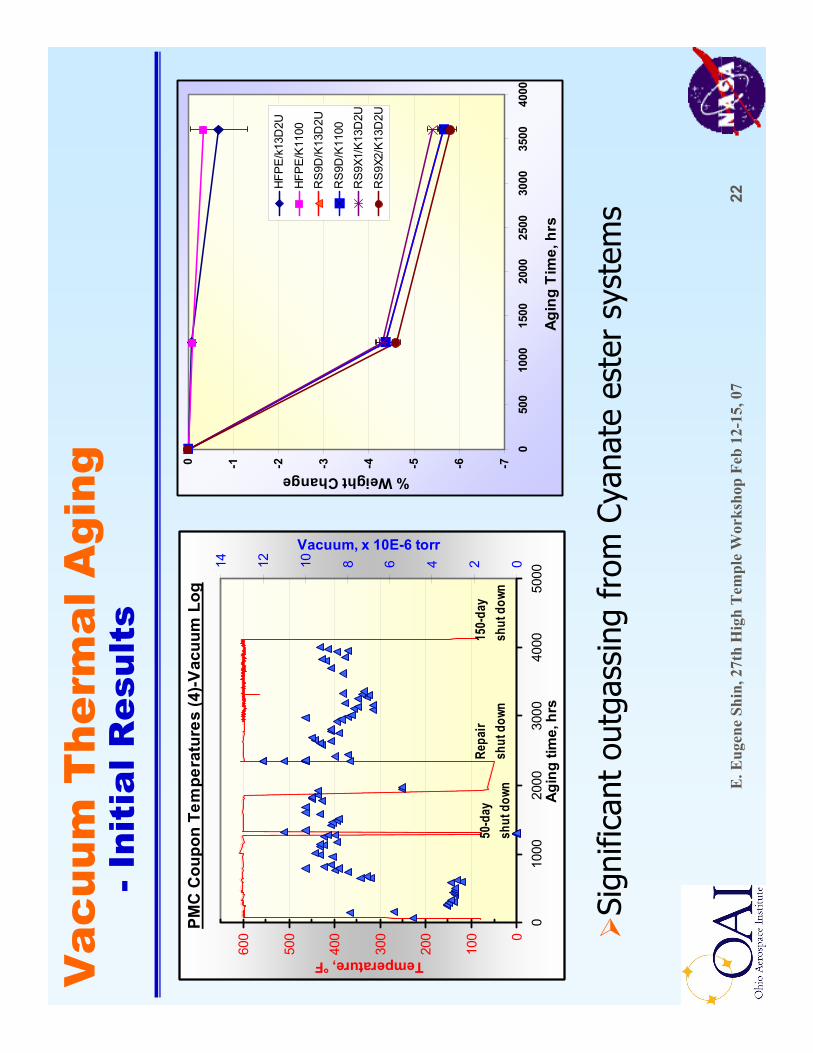
PMC
Cou
pon
Tem
pera
ture
s (4
)-Vac
uum
Log
0
100
200
300
400
500
600
010
0020
0030
0040
0050
00Ag
ing
time,
hrs
Temperature, °F
02468101214
Vacuum, x 10E-6 torr
50-d
aysh
ut d
own
150-
day
shut
dow
n Re
pair
shut
dow
n -7-6-5-4-3-2-10
050
010
0015
0020
0025
0030
0035
0040
00
Agin
g Ti
me,
hrs
% Weight Change
HFP
E/k
13D
2U
HFP
E/K
1100
RS9
D/K
13D
2U
RS9
D/K
1100
RS9
X1/K
13D
2U
RS9
X2/K
13D
2U
Sign
ifica
nt o
utga
ssin
g fr
om C
yana
tees
ter
syst
ems

E. E
ugen
e Sh
in, 2
7th
Hig
h T
empl
e W
orks
hop
Feb
12-1
5, 0
723
RS-
9##/
K13
D2U
com
posi
tes,
6-p
ly [0
, +30
, -30
] 1S
pane
ls
5678910 Modulus, GPa
Stra
ight
Re
sinVG
CNF
mod
ified
VGCN
F+Ex
Gf
mod
ified
+11%
+0.3
%
30405060 Strength, MPa
Stra
ight
Re
sinVG
CNF
mod
ified
VGCN
F+Ex
Gf
mod
ified
+16%
+3%
0.5
0.6
0.7
0.8
0.9
1.0
Strain-to-failure, %
Stra
ight
Re
sinVG
CNF
mod
ified
VGCN
F+Ex
Gf
mod
ified
+19%
+24%
Tran
sver
se (9
0°) T
ensi
le P
rope
rties
(Not
nor
mal
ized
by
F.V
.F)
Bas
elin
e co
ntro
l at R
T @
t=0
Vac
uum
The
rmal
Agi
ng-I
niti
al R
esul
ts
Posi
tive
effe
cts
of n
ano-
mod
ifica
tions
on
mec
hani
cal p
rope
rty

E. E
ugen
e Sh
in, 2
7th
Hig
h T
empl
e W
orks
hop
Feb
12-1
5, 0
724
Bas
elin
e co
ntro
l pro
perti
es a
t RT
@ t=
0(T
ested
by M
ateria
l Inno
vatio
ns In
c (MI
I); N
ot no
rmali
zed b
y F.V
.F)
RS-
9D+V
GC
NF+
ExG
f/ K
13D
2U la
min
ate
RS-
9D+V
GC
NF/
K
13D
2U la
min
ate
RS-
9D S
trai
ght/
K13
D2U
lam
inat
e
PMC
Lam
inat
e typ
e and
test
dire
ctio
n
1.2
1.2
1.3
Z-di
r.84
8891
90°
300
322
345
0°
2.1
2.2
2.2
Z-di
r.77
7983
90°
281
297
322
0°1.
61.
71.
7Z-
dir.
8890
9390
°30
432
634
60°
150
°C10
0 °C
30 °C
Con
duct
ivity
*, W
/mK
*MII
inte
rnal
Ste
ady
Stat
e Th
erm
al C
ondu
ctiv
ity M
etho
d
Vac
uum
The
rmal
Agi
ng-I
niti
al R
esul
tsR
S-9#
#/K
13D
2U c
ompo
site
s, 6
-ply
[0, +
30, -
30] 1
Spa
nels

E. E
ugen
e Sh
in, 2
7th
Hig
h T
empl
e W
orks
hop
Feb
12-1
5, 0
725
PM
C R
adia
tion
Har
dnes
s
Hig
h en
ergy
rad
iatio
n ca
n le
ad t
o ch
ain
scis
sion
(so
ften
ing)
or
cros
s-lin
king
(ha
rden
ing)
in p
olym
ers
Elec
tron
Bea
m (β
part
icle
) is
a c
ost
effe
ctiv
e &
saf
e w
ay t
o su
rvey
the
rad
iatio
n se
nsiti
vity
of
mat
eria
ls &
com
pone
nts
PMCs
exp
osed
to
20, 2
00, &
400
Mra
dfr
om 4
.5 M
eVe-
beam
A:H
FPE/
K13D
2U, C
:RS-
9D/K
13D
2U, F
:RS-
9X (
VGCN
F+Ex
Gf)
/K13
D2U
Expo
sure
led
to n
o m
easu
rabl
e w
eigh
t lo
ss, a
goo
d in
dica
tion
that
th
ere
was
no
sign
ifica
nt c
hang
es in
che
mis
try
Oth
er e
valu
atio
ns (
e.g.
, Tg,
Td,
Cp,
CTE
, TC,
axi
al &
tra
nsve
rse
tens
ile
prop
ertie
s, F
VF, a
nd v
oid
cont
ent
etc)
are
und
erw
ay
PMC
A-0
.046
±0.
053
-0.1
06±
0.19
0-0
.013
±0.
086
C0.
131
±0.
102
0.01
9±
0.31
00.
194
±0.
218
F0.
053
±0.
112
-0.0
89±
0.38
60.
134
±0.
208
200
Mra
d40
0 M
rad
20 M
rad
E. E
ugen
e Sh
in, 2
7th
Hig
h T
empl
e W
orks
hop
Feb
12-1
5, 0
726
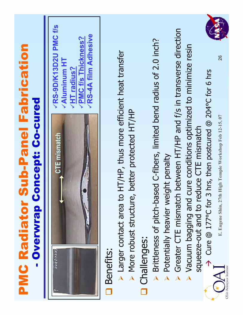
PM
C R
adia
tor
Sub
-Pan
el F
abri
cati
on-O
verw
rap
Con
cept
: Co-
cure
d
Bene
fits:
Larg
er c
onta
ct a
rea
to H
T/H
P, t
hus
mor
e ef
ficie
nt h
eat
tran
sfer
Mor
e ro
bust
str
uctu
re, b
ette
r pr
otec
ted
HT/
HP
Chal
leng
es:
Britt
lene
ss o
f pi
tch-
base
d C-
fiber
s, li
mite
d be
nd r
adiu
s of
2.0
inch
?Po
tent
ially
hea
vier
wei
ght
pena
ltyG
reat
er C
TE m
ism
atch
bet
wee
n H
T/H
P an
d f/
sin
tra
nsve
rse
dire
ctio
nVa
cuum
bag
ging
and
cur
e co
nditi
ons
optim
ized
to
min
imiz
e re
sin
sque
eze-
out
and
to r
educ
e CT
E m
ism
atch
Cure
@ 1
77°C
for
3 h
rs, t
hen
post
cure
d @
204
°C f
or 6
hrs
RS-
9D/K
13D
2U P
MC
f/s
Alu
min
um H
TH
T ra
dius
?PM
C f/
sTh
ickn
ess?
RS-
4A fi
lm A
dhes
ive
CTE
mism
atch

E. E
ugen
e Sh
in, 2
7th
Hig
h T
empl
e W
orks
hop
Feb
12-1
5, 0
727
PM
C R
adia
tor
Sub
-Pan
el F
abri
cati
on-O
verw
rap
Con
cept
: Co-
cure
d[0
/15/-1
5/0]–
HT(R
1.75”
)–[0
/15/-1
5/0]
[0/15
/-15/0
] 1S–H
T(R1
.5”)–
[0/15
/-15/0
] 2S
IR T
herm
o-gr
aphs
; Da
rker
area
slo
wer c
oolin
g cr
acks
, dela
m,
or d
ebon
ding
etc.
Crac
ks d
ue t
o CT
E m
ism
atch
, not
by
HT
curv
atur
e si
nce
both
sid
e cr
acke
dPo
or b
ondi
ng d
ue t
o la
ck o
f re
sin
+
CTE
mis
mat
ch
Crac
ks o
n fr
ont
8-pl
y f/
s, a
lso
dela
min
ated
and
/or
debo
nded
16
-ply
Cr
ack-
free
and
goo
d bo
ndin
g!Rol
e of
HT
curv
atur
e?

E. E
ugen
e Sh
in, 2
7th
Hig
h T
empl
e W
orks
hop
Feb
12-1
5, 0
728
PM
C R
adia
tor
Sub
-Pan
el F
abri
cati
on-O
verw
rap
Con
cept
: Co-
cure
d[0
/15/-1
5/0] 2S
–HT(
R1.5”
)–[0
/15/-1
5/0] 1S
[0/15
/-15/0
] 2S–[
RS4A
] 2-HT(
R1.0”
)–[R
S4A]
2-[0/1
5/-15
/0]2S
Cure
d
Pos
tcur
edCu
red
P
ostc
ured
No
crac
ks o
n 16
-ply
des
pite
of
curv
atur
e,
but
debo
nded
aft
er P
C du
e to
cur
vatu
re
Crac
ks o
n 8-
ply
due
to C
TE m
ism
atch
, an
d lo
caliz
ed d
elam
and/
or d
ebon
ding
Thin
sin
gle
crac
k on
bot
h 16
-ply
f/s
Addi
tiona
l cra
ck &
loca
lized
del
am/d
ebon
daf
ter
PC o
n fr
ont
f/s
due
to c
urva
ture
Stro
ng/r
igid
adh
esiv
e bo
nd c
ause
d gr
eate
r CT
E m
ism
atch
?

E. E
ugen
e Sh
in, 2
7th
Hig
h T
empl
e W
orks
hop
Feb
12-1
5, 0
729
PM
C R
adia
tor
Sub
-Pan
el F
abri
cati
on-A
dhes
ive-
Bon
ding
Con
cept
Bene
fits:
Easi
er f
abric
atio
n, L
ight
er, a
nd g
ood
man
ufac
tura
bilit
y
Chal
leng
es:
Thru
-thi
ckne
ss t
herm
al c
ondu
ctiv
itySt
rong
and
rob
ust
bond
ing
Vacu
um b
aggi
ng a
nd c
ure
cond
ition
s (a
utoc
lave
) op
timiz
ed t
o m
inim
ize
resi
n sq
ueez
e-ou
t an
d to
red
uce
CTE
mis
mat
ch
PMC
f/s
cure
d @
193
°C f
or 2
hrs
st
and.
Sur
face
pre
p H
T bo
nded
&
cure
d @
177
°C f
or 3
hrs
al
lpos
tcur
ed @
204
°C f
or 6
hrs
RS-
9D/K
13D
2U P
MC
f/s
HT
mat
eria
ls: S
S vs
. Al
RS-
4A fi
lm A
dhes
ive
(0.0
31 p
sf)
Adh
esiv
e th
ickn
ess?

E. E
ugen
e Sh
in, 2
7th
Hig
h T
empl
e W
orks
hop
Feb
12-1
5, 0
730
PM
C R
adia
tor
Sub
-Pan
el F
abri
cati
on-A
dhes
ive-
Bon
ding
Con
cept
SS H
T-[R
S4A]
1-[0/2
5/-25
/0]1S
Cure
d-po
stcu
red
pane
ls
No
visu
al d
amag
e on
PM
C f/
san
d re
ason
able
bon
ding
reg
ardl
ess
of H
T ty
pe o
r bo
ndlin
e th
ickn
ess
3-la
yer
adhe
sive
m
ore
resi
n fil
let
form
ed a
t H
T ed
ges
SS H
T-[R
S4A]
3-[0/2
5/-25
/0]1S
AL H
T-[R
S4A]
3-[0/2
5/-25
/0]1S
E. E
ugen
e Sh
in, 2
7th
Hig
h T
empl
e W
orks
hop
Feb
12-1
5, 0
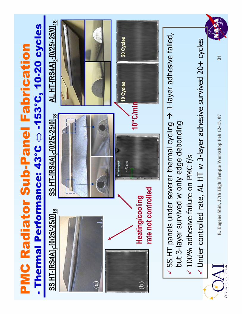
731
PM
C R
adia
tor
Sub
-Pan
el F
abri
cati
on-T
herm
al P
erfo
rman
ce: 4
3°C
⇔-1
53°C
, 10-
20 c
ycle
sSS
HT-
[RS4
A]1-[
0/25/-
25/0]
1S
SS H
T pa
nels
und
er s
ever
er t
herm
al c
yclin
g 1-
laye
r ad
hesi
ve f
aile
d,
but
3-la
yer
surv
ived
w o
nly
edge
deb
ondi
ng10
0% a
dhes
ive
failu
re o
n PM
C f/
sU
nder
con
trol
led
rate
, AL
HT
w 3
-laye
r ad
hesi
ve s
urvi
ved
20+
cyc
les
SS H
T-[R
S4A]
3-[0/2
5/-25
/0]1S
AL H
T-[R
S4A]
3-[0/2
5/-25
/0]1S
Heat
ing/
cool
ing
rate
not
cont
rolle
d10
°C/m
in

E. E
ugen
e Sh
in, 2
7th
Hig
h T
empl
e W
orks
hop
Feb
12-1
5, 0
732
PM
C R
adia
tor
Sub
-Pan
el F
abri
cati
on-H
T-P
MC
bon
ding
eva
luat
ion
Sub-
pane
l to
be s
ectio
ned
into
~0.
6”w
ide
test
cou
pons
−Bo
th o
verw
rap
and
adhe
sive
-bo
nded
pan
els
−O
ptim
ized
sec
tioni
ng w
/ a
low
sp
eed
diam
ond
saw
not
to
dam
age
bond
line
Test
ed in
lap-
shea
r m
ode;
Te
st f
ixtu
res
desi
gned
and
fa
bric
ated
Test
ed a
t RT
and
177°
C (3
50°F
)
Back
ing
plat
e (S
teel
)w
/ gr
it bl
aste
d fin
ish
Adhe
sive
Har
dene
d th
read
ed r
od
Low
er g
rip p
late
(St
eel)
Hol
ding
pla
te (
Stee
l)
R2.
0″
1.0″
1.5″
1.25
″
1.5″
1.0″
0.75
″0.5″
0.2″
thic
k
0.2″
thic
k
Test
cou
pon
(6”
x 0.
6”)
1.0″
2.0″
2.0″
PMC
HT
(ove
rwra
pped
or b
onde
d
Back
ing
plat
e (S
teel
)w
/ gr
it bl
aste
d fin
ish
Adhe
sive
Har
dene
d th
read
ed r
od
Low
er g
rip p
late
(St
eel)
Hol
ding
pla
te (
Stee
l)
R2.
0″
1.0″
1.5″
1.25
″
1.5″
1.0″
0.75
″0.5″
0.2″
thic
k
0.2″
thic
k
Test
cou
pon
(6”
x 0.
6”)
1.0″
2.0″
2.0″
PMC
HT
(ove
rwra
pped
or b
onde
d

E. E
ugen
e Sh
in, 2
7th
Hig
h T
empl
e W
orks
hop
Feb
12-1
5, 0
733
Sum
mar
yD
esig
n an
d ca
ndid
ate
mat
eria
l sel
ectio
n w
ere
mad
e fo
r PM
C ra
diat
or
deve
lopm
ent;
an
d de
sign
and
fab
ricat
ion
of P
MC
f/s
pane
ls w
ere
com
plet
ed
Nan
o-co
mpo
site
s w
/ tw
o co
nduc
tive
nano
fill
ers
wer
e ev
alua
ted
for
TC
enha
ncem
ent,
but
the
impr
ovem
ent
was
ver
y lim
ited
yet
Perf
orm
ance
and
dur
abili
ty e
valu
atio
ns o
f PM
C f/
sin
clud
ing
vacu
um t
herm
al
agin
g, r
adia
tion
hard
ness
, and
mic
rocr
ack-
TC r
elat
ion
wer
e in
itiat
edFo
r ov
erw
rap
conc
ept,
the
rad
ius
of H
T cu
rvat
ure
shou
ld b
e gr
eate
r th
an 4
.45
cm
(1.7
5 in
).
PMC
face
shee
t sh
ould
be
16 p
lies
or h
ighe
r on
bot
h fr
ont
and
back
si
de o
f th
e H
T ov
erw
rap
sect
ion.
The
n, w
eigh
t sa
ving
con
cern
? M
icro
slo
ts o
r ho
les
to r
educ
e w
eigh
t of
HT
Com
bina
tion
of o
verw
rap
and
adhe
sive
bon
ding
is s
till p
ursu
able
opt
ion,
but
m
ore
duct
ile/s
oft
adhe
sive
sys
tem
s w
ith r
easo
nabl
e bo
nd s
tren
gth,
goo
d th
erm
al
cond
uctiv
ity, a
nd h
igh
tem
pera
ture
cap
abili
ty, e
.g.,
cond
uctiv
e na
no-m
odifi
ed
silic
on b
ased
adh
esiv
e w
ould
be
mor
e su
itabl
e fo
r th
e ap
plic
atio
n?Fo
r th
e ad
hesi
ve-b
ondi
ng c
once
pt, t
he R
S-4A
Cya
nate
este
r fil
m a
dhes
ive
perf
orm
ed w
ell f
or b
oth
SS a
nd A
l HT
with
RS-
9D/K
13D
2U P
MC
f/s.
Thic
ker
adhe
sive
laye
r, ~
0.04
cm
(0.
016
in),
was
rec
omm
ende
d fo
rth
e ad
hesi
ve-
bond
ing
optio
n ba
sed
on t
herm
al p
erfo
rman
ce, a
nd s
izab
le r
esin
fill
et f
orm
ed a
t th
e ed
ges
of H
T w
ould
impr
ove
bond
ing
inte
grity
HT-
PMC
f/s
bond
ing
inte
grity
will
be
quan
titat
ivel
y ev
alua
ted

E. E
ugen
e Sh
in, 2
7th
Hig
h T
empl
e W
orks
hop
Feb
12-1
5, 0
734
Futu
re W
ork
Pla
n
Com
plet
e va
cuum
the
rmal
agi
ng a
t al
l thr
ee T
sCo
mpl
ete
mic
rocr
ack-
TC r
elat
ions
Com
plet
e bo
nd s
tren
gth
eval
uatio
n D
own-
sele
ct a
nd o
ptim
ize
mat
eria
l, de
sign
and
pr
oces
s D
evel
op f
abric
atio
n-m
anuf
actu
ring
spec
ifica
tions
for
a
full-
size
com
pone
nt s
cale
PM
C ra
diat
or p
anel
sCo
ntin
ue n
ano-
mod
ifica
tion
for
thru
-thi
ckne
ss T
C im
prov
emen
t ba
sed
on “
cock
tail
Des
ign”
appr
oach

E. E
ugen
e Sh
in, 2
7th
Hig
h T
empl
e W
orks
hop
Feb
12-1
5, 0
735
Max
imiz
e/op
timiz
e th
e th
ru-t
hick
ness
the
rmal
con
duct
ivity
of
cont
inuo
us f
iber
re
info
rced
PM
C, s
peci
fical
ly f
ocus
ing
onSy
ner
gist
ic c
hem
ical
, ph
ysic
al, a
nd
stru
ctu
ral m
odif
icat
ion
s fr
om
mol
ecu
lar
leve
l to
nan
o, m
icro
, an
d m
acro
sca
les
incl
udi
ng,
Sele
ctio
n of
hig
h TC
con
stitu
ent
Mat
eria
ls,
Mol
ecul
ar m
odifi
catio
ns o
f m
atrix
res
in s
yste
m
Hig
h TC
fill
er r
einf
orce
men
t bu
t vi
a co
ckta
il de
sign
fro
m n
ano
to m
acro
sca
le t
o m
axim
ize
conn
ectiv
ity/a
rchi
tect
ural
inte
ract
ions
Fille
r lo
adin
g ra
tio o
ptim
ized
in t
erm
s of
con
nect
ivity
, pro
cess
abili
ty, a
nd w
eigh
t/de
nsity
co
ntro
l
Mat
eria
l-pro
cess
sel
ectio
n ba
sed
on p
erfo
rman
ce p
redi
ctio
n/th
eore
tical
mod
elin
gO
ptim
izin
g m
ater
ial p
roce
ssin
g (m
ixin
g/di
sper
sing
) an
d st
ruct
ure
(des
ign
and
fabr
icat
ion)
O
ptim
izin
g fil
ler
surf
ace
trea
tmen
t fo
r im
prov
ed w
ettin
g an
d bo
ndin
g w
/ m
atrix
re
sin
Mul
ti-fu
nctio
naliz
atio
n; in
add
ition
to
high
TC,
impr
ove
elec
tric
al c
ondu
ctiv
ity a
nd
EMI
shie
ldin
g as
wel
l as
good
mec
hani
cals
Futu
re W
ork
-“C
ockt
ail D
esig
n”A
ppro
ach

E. E
ugen
e Sh
in, 2
7th
Hig
h T
empl
e W
orks
hop
Feb
12-1
5, 0
736
Coc
ktai
l Mod
ifica
tion
Con
cept
for
Z-
Ther
mal
Con
duct
ivity
Impr
ovem
ent
Dim
ensi
ons
Fibers:
K13
D2U
or K
1100
: ~10
µm
dia
M40
J &
M60
J: 5
µm
dia
Matrix:
Mol
ecul
ar m
odifi
catio
ns fo
r hig
h TC
; Ep
oxie
s, C
yana
tees
ters
, Pol
yim
ides
Fillers:
Met
al F
lake
s/Fi
bers
/Sph
eres
(MF)
etc
:~
1 m
m L
x ~
0.5
mm
W x
~25
µm
Th
Cho
pped
Fib
ers
(CF)
: 3
–5
µm Ø
x ~
50 µ
m L
Car
bon
Bla
cks
(CB
): ~
3 –
8 µm
ØEx
folia
ted
Gra
phite
Fla
kes
(EG
f):
~ 30
µm
L x
~ 1
0 µm
W x
sub
-µm
Th
Car
bon
Nan
o Fi
ber (
CN
F):
~ 0.
02 µ
m Ø
x ~
5 -1
0 µm
LN
ano-
part
icul
ates
(NP;
met
allic
/cer
amic
): ~
10 –
100
nm Ø
e.g.
, Com
posi
te w
/ 60
% F
VF+
tot
al u
p to
20
wt%
Fill
er lo
adin
g
CB
CN
F
EG
f
CF
orM
F
NP
Opt
imiz
e fi
ller
load
ing
rati
os, s
hap
e fa
ctor
s, a
nd
tota
l am
oun
t in
ter
ms
of
ther
mal
con
duct
ivit
y, p
roce
ssab
ility
, an
d co
mpo
site
per
form
ance
an
d pr
oper
ties
Futu
re W
ork
-“C
ockt
ail D
esig
n”A
ppro
ach