277 276 creating solutions - g-w
TRANSCRIPT

276 Section 3 Creating Technology
Did You Know?
Mechanical drawings use symbols that help explain features of the drawings. These symbols are standard so everyone who looks at a drawing can understand it. Different types of drawings use different sets of symbols.
The symbols used in welding drawings explain how the parts should be welded together. Some common welding symbols include the following:
Symbols used in engineering drawings include the following:
Some common architectural symbols include the following:
C h a p t e r 1 3Creating Solutions
Seam
Weld “V” groove
Weld all around
Diameter
Drill through
Countersink
Door
Window
This chapter covers the benchmark topics for the following Standards for Technological Literacy:
3 8 9 1 0 11
Reinforce
Review the problem seeking steps of the design process.
TechnoFact
Many of the designs communicated in the architectural field are created by architectural engineering technicians. The role of an architectural engineering technician is to work closely with an architect or engineer to prepare design drawings. Most fields of engineering have technicians working in support roles with the engineers.
Chapter 13 Creating Solutions 277
Objectives
The information given in this chapter will help you do the following:
Explain the concept of ideation.
Explain brainstorming, graphic organizers, and questioning.
Summarize the qualities of a rough sketch.
Summarize the qualities of a refined sketch.
Apply the procedure for creating sketches.
Compare shading and shadowing.
Create an isometric sketch.
Create an oblique sketch.
Create a perspective sketch.
Key Words
These words are used in this chapter. Do you know what they mean?
boxbrainstormingconecylinderelements of designgraphic organizerideationisometric sketchoblique sketchorthographic drawingpictorial drawingpyramidquestioningrefined sketchrough sketchshadingshadowingsketchspherethumbnail sketch
Preparing to ReadLook carefully for the main ideas as
you read this chapter. Look for the details that support each of the main ideas. Use the Reading Organizer at the end of the chapter to organize the main and supporting points.
The design process can be divided into two sections: problem seeking and problem solving. The first two steps of the process are problem seeking. In step one, the problem is identified. A design brief is created. The problem is then researched in step two. Both of these steps deal with seeking information about the problem. Step three is the first step to involve solving the problem. In this step, the designers begin to think of ways the problem can be solved. They develop many ideas and draw sketches for each of the ideas. See Figure 13-1. The sketches help to explain the designers’ ideas to others. The ideas and sketches developed are then refined, modeled, and tested in the next steps of the design process.
IdeationSome people might come to this
step and think they already know what their final solution is. They might feel that developing a number of solutions is a waste of time. This is the wrong attitude to have. Designers must explore a number of ideas. The more ideas explored, the better the design will be. Designers should generate original and creative ideas. They have to think broadly and develop a wide variety of ideas. If designers use narrow thinking, their designs will not be unique. For example, imagine you are designing a telephone. You should explore many different ideas (broad thinking). One idea might be a phone fitting in your ear, similar
This sample chapter is for review purposes only. Copyright © The Goodheart-Willcox Co., Inc. All rights reserved.

Brainstorm
Have the students generate ideas for solutions to the problem of telephone communication.
TechnoFact
Divergent thinking is the term for thinking of many different ideas. The narrowing and focusing of ideas is known as convergent thinking.
278 Section 3 Creating Technology
to a hearing aid. Another idea might be a digital phone with a computer video display. See Figure 13-2. These are two different solutions to the design of a telephone. You do not want to create ideas such as a red desk phone and a black desk phone. That is narrow thinking. These ideas are essentially the same thing, with only the color differing. The small changes, such as color, can be made later. It is impor-tant that designers explore many ideas. Exploring ideas is called ideation.
Creating a number of new ideas to solve a problem is ideation. The process of ideation is creative and imaginative. See Figure 13-3. Creativity leads to new ideas and solutions. The solutions created at this step should be simple and rough. Later in the process, the solutions will be revised and refined. Ideation begins by reviewing the problem and design brief. Remember, the solutions developed must solve the problem. The solution must also fit the criteria and limitations. After reviewing the design brief, the research conclusions must be reviewed. This review helps the designer understand
Figure 13-1. Sketches are ideas on paper. (Design Central)
Figure 13-2. Broad thinking leads to new solutions to problems. (Motorola, Inc.)
Reinforce
Discuss the importance of reviewing the design brief before creating ideas.
Brainstorm
Ask the students to identify the environments they work best in.
TechnoFact
Creative thinking leads to many new ideas, designs, and inventions. In 1960, Alfred Fielding and Marc Chavannes created a textured wall covering that was not very successful. They went back to the ideation stage and generated ideas for other potential uses. They decided that their textured wall covering would work better as a packing material; we now know their invention as Bubble Wrap® material.
Chapter 13 Creating Solutions 279
what others have done and what people want from the solution.
Ideation is a free-flowing activity. Ideas must be able to flow without others shooting them down. In ideation, all ideas are good ideas. There are no right or wrong answers. It is important to record (sketch or write down) all ideas. Ideas seeming silly or wild at first might make more sense later. If you do not record them, you might forget some good ideas.
The environment you use to create solutions is very important. You must be able to concentrate on the problem. In front of the television at home might not be the best place to focus on creating ideas. Many designers find quiet places to work. They might leave their offices and work outside or in a library. See Figure 13-4. The only things needed to create ideas are a pencil and paper. Ideation can be done almost anywhere. When creating ideas, designers often flip through magazines or
Figure 13-3. Unique products are the results of creativity and imagination. (Patent No. 5,050,855, U.S. Patent and Trademark Office)
Figure 13-4. Designers often work best in quiet areas away from their offices and desks. ( iStockphoto.com/LajosRepasi)

Standards for Technological Literacy
9
Discussion
Ask the students why it is important to have a leader for brainstorming sessions.
Extend
As a class, use brainstorming to generate ideas for a new product.
Discussion
Ask the students why brainstorming is only used to generate ideas and not to choose a final solution.
TechnoFact
In 1941, Alex Osborn created the technique of brainstorming. He was an advertising executive who felt the typical meetings were not allowing the creation of ideas. He developed four rules for his meetings: No criticism of ideas, go for large quantities of ideas, build on each other’s ideas, and encourage wild and exaggerated ideas.
280 Section 3 Creating Technology
books. They might even listen to inspiring music. Designers often see pictures or hear words that spark ideas for solutions to their own problems.
There are several different methods of ideation. Some people find one works better for them than others do. Three of the main methods are brainstorming, graphic organizers, and questioning.
BrainstormingBrainstorming is a method used to
develop many ideas. This method is useful in small groups for coming up with unusual solutions. The group members are often selected to include people with different backgrounds. It is helpful to have people with different knowledge and experiences because they bring new and different ideas to the activity. Brainstorming is a process that begins with the design problem. The process has several steps.
In the first step, the small group must choose a leader and a recorder. The leader starts and ends the brainstorming and makes sure the group stays on task. The recorder is in charge of recording all the ideas shared. See Figure 13-5.
Next, the leader sets a time limit. Brainstorming is done best when a time limit is set. The group members stay more focused if they have only a certain amount of time. At this point, the leader shares the design brief with the group. The leader makes sure everyone understands the problem. The ideas generated must solve the problem. The group leader also shares the research conclusions. It is important that the research is used to come up with ideas.
The members of the small group all focus on the problem. The group leader then asks for ideas. The group members try to list as many creative ideas as possible. Solutions can become very creative when people get ideas from each other. One person might present a new idea. The new idea might spark an idea in your mind. You might never have thought of your idea without the other person’s idea. Brainstorming works well when the group members use each other’s ideas to add to their own. In brainstorming, as in other forms of ideation, it is important that there is no criticism. If people are criticizing or making fun of ideas, people do not want to share their thoughts. The best thoughts might not be shared if people are afraid to give their ideas.
Throughout the whole session, the recorder makes notes of all the ideas devel-oped. When the time is up, the leader must stop the session. The leader might ask all the group members for one final idea. Once the group is done, the brainstorming is over. The notes will be reviewed later in the design process. The main purpose of brainstorming is to develop a list of ideas. The purpose is not to choose the final solution.
Graphic OrganizersA graphic organizer is another
method of developing ideas. This method is a diagram that helps to organize thoughts. One person or a group of people can create a graphic organizer.
Figure 13-5. A typical brainstorming session can generate many ideas.
Standards for Technological Literacy
9
Demonstrate
Select a product and show the students how to create a graphic organizer of its function or parts.
TechnoFact
Graphic organizers are used for a number of purposes. They are useful in clarifying the relationships among concepts. They are often used as aids for comprehension and vocabulary acquisition.
Chapter 13 Creating Solutions 281
To create a graphic organizer, designers begin with a blank sheet of paper. They write the problem in the middle of the sheet and circle it. The designers then create branches from the middle. The branches are the major features or func-tions of the design. If the design problem is to design a new camera, the word camera goes in the middle. See Figure 13-6. The branches are features, such as type of camera, loading the film or media, focusing the picture, taking the picture, and changing the settings. Below the
branches, the designer lists the possible ways to design the features or functions. Under the “Taking pictures” branch, the solutions might be a button on the top of the camera, a voice-activated control, an automatic timer, and a handheld switch.
The graphic organizer helps to make sure all the features of the problem are considered. This organizer is also helpful because all the solutions are listed on the same sheet of paper. It is easy to see all the ideas you have developed.
Career HighlightArchitects
The Job: Architects are licensed professionals who are trained to design buildings. They identify a client’s needs, develop building concepts to meet these needs, and prepare plans for the building. Architects design the overall look of buildings and develop plans and specifications that construction personnel will use in erecting the structure. They must be able to communicate their vision and plans to clients and construction managers.
Working Conditions: These professionals spend a great deal of their time in offices, consulting with clients and developing drawings. In addition, they spend time visiting construction sites to review projects under construction.
Education and Training: All architects must be licensed before they contract to provide architectural services. Many architecture-school graduates work for another architect, however, while they are in the process of becoming licensed. In most states, obtaining a license requires a degree in architecture from an accredited university program. Most of these programs are five-year bachelor of architecture programs. Typically, architecture programs have courses in architectural history, building design, structures, and construction methods. They also require several professional-practice, mathematics, science, and liberal arts classes.
Career Cluster: Architecture & ConstructionCareer Pathway: Design/Pre-Construction

Standards for Technological Literacy
9
Demonstrate
Complete a simple process, such as opening a door or tying a shoe, and show the students how to use the questioning process to record the steps.
Discussion
Ask the students which method of ideation they would most likely use to generate ideas. Have them explain their answers.
TechnoFact
Several people have developed computer-aided brainstorming applications. These applications are designed for people who lack creativity, but are in need of a creative solution to a problem.
282 Section 3 Creating Technology
QuestioningQuestioning is the third method of
ideation. This method is done differently from brainstorming and graphic organizing. Questioning is a process in which the designer asks the question “Why?” This process is done while working with existing products. See Figure 13-7. The designer asks why things are done the way they are in the existing product. Imagine you are designing a better way to toast bread. If you were using the questioning method, you would locate a toaster and a loaf of
bread. You would use the toaster and ask yourself questions such as the following:
Why is the bread loaded from the top?
Why do I push a lever to start the toaster?
Why does a knob control the darkness scale?
The key to questioning is that the ques-tions are written. Once the questions are asked, they need to be solved. Designers often find creative solutions to problems because they asked “Why?”
Brainstorming, graphic organizers, and questioning are all useful methods of creating ideas. These approaches to ideation all result in lists of solutions. Lists, however, are not always the best way to describe solutions. Have you ever tried to describe an idea you had using a list? Describing an idea using a list can be very difficult to do. Imagine someone asked you to describe how your bicycle works or how the White House looks. Are these things easy to describe? They would prob-ably be hard to describe without drawing the gears of your bike or the front of the White House.
Loading film
Type Focusing picture
Changing settings Taking pictures
Voice activated
Timer
Handheld switch
Camera
Figure 13-6. Graphic organizers help generate ideas.
Figure 13-7. Questioning relies on designers to ask questions about ways they use a product.
Standards for Technological Literacy
8 9 11
Discussion
Ask the students why sketches make it easier to understand an idea.
Extend
Have the students create sketches of ideas they have for new products.
Research
Have the students use the Internet to find various sketches developed by designers.
TechnoFact
Sketching can be traced back to the prehistoric use of natural materials and surfaces, like mud, chalk, and clay.
TechnoFact
The use of sketches can even be seen in artistic design. Many painters use the technique of underdrawing. Underdrawing is the creation of a sketch on the canvas before the artist begins to paint.
Chapter 13 Creating Solutions 283
SketchingUsing a sketch can make describing
ideas much easier. The methods of ideation can be very helpful in coming up with ideas. Sketches are useful, however, for describing the ideas to other people. See Figure 13-8. Sketches are tools that help designers communicate their ideas. They are a way to record the designers’ thoughts on paper. As thoughts flash into the heads of designers, the designers sketch them so others can see them. Sketching is usually done in two steps:
The first step is often called design sketching, preliminary sketching, or rough sketching. These sketches are quick and simple sketches.
The second step is often called working sketching, final sketching, or refined sketching. These sketches are more detailed and require more time to complete.
Rough SketchesDuring the design process, designers
always have ideas that pop into their heads. This is especially true during the ideation stage. Designers might have finished a brainstorming session and have an idea on the way home or during dinner. For this reason, many designers carry sketch pads and notebooks to record such ideas. When designers forget their sketchbooks, you might see them make sketches on napkins or small pieces of paper. At this point, it is not important what type of paper or writing utensil the designer uses. All that matters is that the designer gets the ideas onto paper. The designers are not concerned with the quality of the sketches. Good designers try to capture as many ideas as they can.
These sketches are called rough sketches. See Figure 13-9. The word rough might seem to suggest that the sketches are hard to understand. This, however, is not the case. Rough just means the sketches are in the early stage of development. They are not completely thought out. Rough sketches are basic ideas showing shapes and outlines. They do not show a great amount of detail.
Rough sketches can be ideas of a complete solution, such as an entire
Figure 13-8. Sketches are used to communicate ideas between one person and another. (Product Development Technologies, PDT)
Figure 13-9. Rough sketches are early sketches showing the basic shapes and outlines. ( iStockphoto.com/feuers)

Standards for Technological Literacy
9 11
Demonstrate
Show the students some examples of refined sketches.
Extend
Explain that the word orthographic is made from two Greek terms: ortho, meaning at right angles, or perpendicular, and graphe, meaning a drawing.
Extend
Have the students try to picture objects in six different views.
TechnoFact
In graphic design, a rough layout is the next step after the thumbnail drawing. A rough layout is a sketch that begins to include the details and sizes that will be found in the final product.
284 Section 3 Creating Technology
bicycle. The bicycle designer creates rough sketches of bicycles of different sizes, shapes, and designs. Size and shape are two elements of design devel-oped using rough sketches. The sketches can also be ideas of smaller parts of the whole solution. See Figure 13-10. In the bicycle example, the rough sketches can be different ideas for the brakes and gears of the bicycle.
These sketches are also known as thumbnail sketches because of their size. Most rough sketches are fairly small, with several rough sketches fitting on a sheet of paper. Good designers are able to create rough sketches fairly quickly. These sketches might take beginners a while to create. The time spent on creating rough sketches is not what is most important. The importance of rough sketches is that many ideas are generated.
Refined SketchesAfter ideation, the designer should
have a large number of rough sketches. These sketches might contain many good ideas. There might be ideas on how to solve the entire problem or how to solve small pieces of the larger problem. The sketches are simply ideas on paper. They make up a library of solutions. The rough sketches need more work done to them before they become proposed solutions to the problem. From the rough sketches, the designer must select the most promising solutions. This is the first time in the entire design process that the ideas can be reviewed. In the brainstorming and rough-sketching stages, all ideas were valid. No ideas were criticized or discarded.
The designer creates new sketches based on the best ideas from the rough sketches. The new sketches are called refined sketches. See Figure 13-11. A refined sketch might focus on one rough sketch. This sketch might, however,
combine parts of several sketches to make one new idea. The sketches combine the ideas ideation created. The purpose of the refined sketch is to narrow down the design ideas. The designer creates several different refined sketches. The best solu-tions will be chosen in the next step of the design process.
The Sketching Process
Sketches are not always easy to create. See Figure 13-12. Sketching is a technique. There is a certain way to sketch. Sketching has several steps: 1. Visualizing the object. 2. Blocking out shapes. 3. Adding an outline. 4. Drawing design features.
Visualizing the ObjectThe technique of sketching begins
with visualizing the object. Visualizing, or seeing, the object might seem to be a simple thing. You might be able to look at an object and sketch it. In rough sketching, however, you might not be able to look at something real. If you are creating a new and innovative product, there is no image at which to look. You might have the idea only in your mind and have to “see” the
Figure 13-10. Some sketches show solutions of only part of a design. (Design Central, design firm; Artromick International, client)
Standards for Technological Literacy
9 11
TechnoFact
A three-view orthographic drawing uses two planes of projection. The front view uses the frontal plane of projection and shows the height and width of the object. The top view shows the width and depth using the horizontal plane. The side view shows the height and depth on the profile plane.
Chapter 13 Creating Solutions 285
Figure 13-11. Refined sketches are more detailed than rough sketches. (Daimler)
Figure 13-12. Sketches help develop ideas. (Design Central)

286 Section 3 Creating Technology
Technology Explainedelegant solution: a product meeting a human need in the simplest, most direct way.
Complex products and devices surround us. Many of these products and devices have all kinds of frills and little add-ons designers thought were necessary. Many of these add-ons, however, complicate the designs and make the products hard to use.
The opposite of this is the product meeting a need in the simplest and most effective way. Engineers call these elegant solutions. These solutions should be the goal of every designer of technological artifacts.
Think of an adhesive bandage, commonly known as the Band-Aid® bandage. This bandage is designed to hold gauze over a small cut or scratch. Can you think of a better solution? Over the years, no one has thought of one. Therefore, the Band-Aid bandage is an elegant solution.
Another commonplace product is the paper clip. See Figure A. The paper clip temporarily holds sheets of paper together. Everyone uses paper clips. No one has improved them. Again, this is an elegant solution.
Think of a number of other devices that work so well that improving them is a challenge. These devices include the zipper, safety pin, stapler, ballpoint pen, pipe cleaner, and thong sandal. Small details might change, such as the types of materials used. The basic design, however, remains the same. Elegant solutions do not, however, have to be simple products. There are many examples of complex technological products that elegantly solve problems.
Consider the Apollo spacecraft. See Figure B. This spacecraft carried three men into space and back with relative ease. The spacecraft’s complex systems propelled and navigated the capsule. The spacecraft provided heat, light, and fresh air for the three astronauts inside. The capsule also protected the astronauts from the outside environment.
Elegant solutions are everywhere. Have you ever tried to read and record large volumes of numerical data? This is a time-consuming process and one prone to error. A bar code reader, such as the one shown in Figure C, makes this task quick and accurate. The unit shown is the size of a handheld calculator. Despite its small size, the device efficiently reads and processes the information coded in the bars. Bar code readers are widely used to take inventory in retail stores.
Figure 13-A. The paper clip is an example of an elegant solution.
Figure 13-B. The Apollo spacecraft is an example of an elegant solution. Complex devices can also be elegant solutions.
Figure 13-C. The bar code reader is an elegant solution to a modern problem.
Standards for Technological Literacy
9 11
Brainstorm
Have the students think of objects representing each of the basic shapes listed on this page.
Demonstrate
Show the students how to create the isometric axes.
TechnoFact
Sketching and geometry are closely related. The shapes used in sketching are commonly encountered in the study of geometry.
Chapter 13 Creating Solutions 287
object in your imagination. Sketching is often thought of as seeing and thinking with a pencil. Good designers can easily see their ideas and use pencils to recreate them. Seeing your ideas takes practice. The more designers sketch, the better they become.
There are two ways designers see objects. They can see objects in either two or three dimensions. When designers see in two dimensions, they see the object in six different views. They see the front, top, left side, right side, back, and bottom. Sketches made in two-dimensional views are called orthographic sketches. See Figure 13-13. Orthographic drawings, which are more precise than sketches, are discussed more in Chapter 17. People who are not trained to read them might find orthographic sketches and drawings hard to understand. At this stage in the design process, it is easier for designers to see ideas in three dimensions. Three dimensions are the easiest because this is how the eye sees things. This is also best because almost all people can under-stand a drawing in three dimensions. Three-dimensional drawings are called pictorial drawings. The three major types of pictorial drawings are isometric, oblique,
and perspective drawings, all of which are discussed later in this chapter.
Once the designers can see the idea, they begin by breaking down the object. Breaking down the idea requires the designers to divide their ideas into basic shapes. Some designers are able to see the basic shapes easily. Other designers must work harder to see the shapes. All objects, however, can be broken into one or more of these basic shapes. See Figure 13-14: Box. A box can be either a cube or a
prism. A cube is a three-dimensional square. All sides of the cube are the same length. A six-sided die is an example of a cube. A prism is very similar to a cube. The difference is that a prism has at least one side that is a different length. A cereal box is a prism.
Cylinder. A cylinder is a round shaft. This shaft has one circle on each end, similar to a tube. A soda pop can is an example of a cylinder.
Sphere. A sphere is a perfectly round object. Baseballs and basketballs are spheres.
Cone. A cone is a shape that is round at one end and comes to a point at the other. An ice-cream cone is an example of a cone.
Pyramid. A pyramid is similar to a cone because it comes to a point at one end. The other end of the pyramid, however, is a square. The Egyptian pyramids are examples of this shape.
Blocking Out ShapesAfter the object or idea has been
broken down into pieces, the sketching begins. The sketching starts by blocking out shapes. Blocking out means drawing light lines where the basic shapes will be. These lines serve as guidelines used to make the sketch. Blocking out is very important for beginners. The more advanced designers are able to block out shapes very quickly.
Figure 13-13. Orthographic sketches show each side as a separate view. (Keith Nelson)

Standards for Technological Literacy
9 11
Demonstrate
Show the students how to draw a box.
Extend
Have the students draw a cube and rectangular prism.
TechnoFact
The first aluminum can entered the beverage market in 1958. Today, all beverage cans in the United States are aluminum. Steel is still used in other countries. Over the years, the weight of the cans has decreased; they are 30 percent lighter than they were twenty years ago.
288 Section 3 Creating Technology
Beginners must take their time to make sure the shapes are correct.
To begin blocking out, the designer draws a vertical line. Next, two lines are drawn at roughly 30°, starting from the bottom endpoint of the vertical line. These three lines are called the isometric axes. The intersection of the isometric axes forms the front corner of the sketch. The shapes can now be blocked into the sketch. Each shape is blocked in a little differently.Boxes
The box uses the intersection of the isometric axes as its front corner. See
Figure 13-15. The vertical line should be drawn to the same height as the object. The line drawn to the left should equal the length. The line to the right should equal the width of the box. Once the lines are drawn, the designer draws a line the same length as the vertical line at the other two endpoints. The designer then connects the three vertical lines. This forms the front and right side of the object. To form the top of the box, the designer draws two additional angled lines, the same length as the other angled lines. The first angled line is drawn from the upper-left corner of the front side
Cylinder
Cone
Box
Sphere
Shapes in Designs
Figure 13-14. The basic shapes can be seen in many common objects. A file cabinet is a box shape. The shape of a cylinder can be seen in a can. Baseballs are spheres. An ice-cream cone is a cone shape. (Sauder Woodworking, The Coca-Cola Company, American Baseball Company)
Standards for Technological Literacy
9 11
Demonstrate
Show the students how to draw a cylinder and a sphere.
Extend
Have the students draw a cylinder and a sphere.
TechnoFact
Cylinders have been used in many inventions. In 1811, Friedrich König and Andreas Bauer revolutionized the printing industry by creating a printing press that used a cylinder. The paper was wrapped around a rotating cylinder as the type moved underneath it.
Chapter 13 Creating Solutions 289
of the box. This line should match the line at the top of the right side of the box. The final line should connect the end of the line that was just drawn to the upper corner of the right side of the box. This creates the top of the box. In a cube, all the lines drawn are the exact same size.Cylinders
The cylinder is drawn using a square at the axes. See Figure 13-16. To begin the cylinder, designers use the angled lines of the axes and draw a square. They then draw an ellipse. An ellipse is an isometric circle. This circle is drawn through the midpoint of each line of the square. This forms the bottom of the cylinder. To make the top of the cylinder, designers draw vertical lines from the corners of the square. They then create a square positioned at the top of the cylinder. The designers draw an ellipse in the top square. To finish the cylinder, they
draw a horizontal line from one corner of the bottom square to the other corner. Two vertical lines are then drawn where the line crosses the ellipse. These create the sides of the cylinder.Spheres
Spheres are drawn by first creating a cube. See Figure 13-17. The cube is created as described previously. Once the cube is drawn, a circle is created inside of it. The circle is drawn so it touches the midpoint of the outside lines of the cube. When the sphere is drawn, it looks similar to a plain circle. In order for the sphere to look three-dimensional, it must be shaded. Shading is discussed later in this chapter.Cones and Pyramids
The cone and pyramid are drawn using the rectangular box. The box is drawn
Step 1
Step 2
Step 3
Step 4
Isometric axes
Figure 13-15. Boxes are sketched using these four steps.
Step 1
Step 2
Step 3
Step 4
Step 5
Figure 13-16. Cylinders are sketched using these five steps.
Standards for Technological Literacy
9 11
Extend
Explain the difference between a cone and pyramid.
Demonstrate
Show the students how to draw a pyramid and a cone.
Extend
Have the students block out a product that uses more than one shape.
Extend
Have the students add an outline to the sketch.
TechnoFact
The most famous examples of the pyramid shape are the pyramids of Egypt. The Great Pyramid of Giza is the largest and most popular. The base covers thirteen acres, and it originally stood 481 high. The pyramid served as a tomb for Khufu.
290 Section 3 Creating Technology
as shown in Figure 13-15. Next, an X is drawn on the top of the box. The center of the X is the center of the top of the box. The center point is the point where the top of the cone or pyramid will come to. To draw a pyramid, the designer draws lines from the bottom corners of the box to the center point. See Figure 13-18. To draw a cone, an ellipse must be drawn on the bottom of the box, just as when creating a cylinder. See Figure 13-19. Lines are then drawn from the sides of the ellipse to the top center point.Combinations
Unless the designs are simple prod-ucts such as ice-cream cones or basket-balls, the sketches created will have more than one basic shape in them. Each of these shapes must be blocked out. You have learned how to block out shapes using the isometric axes. Sketches with more than one shape have more than one set of axes. Imagine designing a guitar. See Figure 13-20. You have several boxes making the shapes of cylinders and
Step 1
Step 2
Step 3
Figure 13-17. Spheres are sketched using these three steps.
Step 1
Step 2
Step 3
Step 4
Figure 13-18. Pyramids are sketched using these four steps.
Step 1
Step 2
Step 3
Step 4
Figure 13-19. Cones are sketched using these four steps.
Standards for Technological Literacy
9 11
Extend
Have the students add design features to their sketches.
TechnoFact
Historians speculate the guitar was invented in Spain during the 1300s. The original guitars were smaller and had four groupings of two strings. It was not until around 1800 that the current arrangement of six strings was developed.
TechnoFact
In many types of design, the design features are the aspects that set different sketches apart. For example, interior designers may have many sketches of the same room. The design features, like furniture, wall coverings, moldings, and colors may be the only differences in the sketches.
Chapter 13 Creating Solutions 291
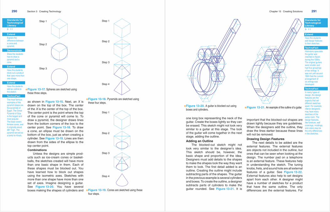
one long box representing the neck of the guitar. Create the boxes lightly so they can be erased. This sketch might not look very similar to a guitar at this stage. The look of the guitar will come together in the next stage, adding the outline.
Adding an OutlineThe blocked-out sketch might not
look very similar to the designer’s idea. This sketch should be, however, the basic shape and proportion of the idea. Designers must add details to the shapes to make the shapes look the way they want them to look. The first detail added is an outline. Creating the outline might include subtracting parts of the shapes. The guitar in the previous example is several cylinders and boxes. To create the outline, a designer subtracts parts of cylinders to make the guitar rounded. See Figure 13-21. It is
important that the blocked-out shapes are drawn lightly because they are guidelines. When the designers add the outline, they draw the lines darker because these lines will not be removed.
Drawing Design FeaturesThe next details to be added are the
external features. The external features are objects not included in the outline, but ones that can be seen when looking at the design. The number pad on a telephone is an external feature. These features help in understanding the sketch. The tuning knobs, frets, and sound hole are all external features of a guitar. See Figure 13-22. External features also help to set designs apart from each other. A designer might have a number of sketches for a product that have the same outline. The only differences are the external features. For
Figure 13-20. A guitar is blocked out using boxes and cylinders.
Figure 13-21. An example of the outline of a guitar.

Standards for Technological Literacy
9 11
Figure Discussion
Point out to the students that the added external features in Figure 13-22 make the sketch look more realistic.
Extend
Have the students practice shading by sketching objects in the room and shading them as they appear.
TechnoFact
Many designers have their own methods of shading and shadowing. There are also a variety of tools designers can use. The tools range from very fine-tipped to very wide-tipped markers and from airbrushes to watercolor brushes. Experienced designers use a combination of tools and techniques to create the look they want.
292 Section 3 Creating Technology
rough sketches, after the external features are added, the sketches are finished. For refined sketches, additional techniques can be used to add more detail and life to the sketches.
Refining TechniquesThere are some techniques that can
be used on refined sketches to make the sketches appear more realistic. Shading and shadowing are the two most common techniques. Both of these techniques illus-trate how the objects will look when placed in light. They add depth and dimension to flat sketches.
ShadingShading is a technique that shows
how light is reflected from an object. This technique relies on a light source. Most designed objects come in contact with
either sunlight or interior lighting. Shading helps to show how the object will look in either of these two light sources. This technique also allows the designer to see the shape and form of the object. To begin shading, the designer must determine from which direction the light source is coming. The direction of the light source determines how the object is shaded. The standard is to imagine that the light source is located over the designer’s left shoulder.
There are several techniques used in shading. The most common is using different tones to create the shading effects. A tone is a shade of color. Gray is a tone between black and white. In this method of shading, the area of the object closest to the light source is the lightest tone. The area furthest from the light is the darkest. This effect can be created with the edge of a pencil or markers. When using a pencil, designers create the darker areas in one of two ways. They can either press harder in the darker areas or go over these areas several times. When using markers to shade, the designer selects markers of different tones to create light and dark areas. See Figure 13-23.
Other shading techniques use either dots or lines instead of different tones
Figure 13-22. A guitar with the external features.
Figure 13-23. Shading and shadowing help designers see the shape and form of the object. (Design Central)
Standards for Technological Literacy
9 11
Demonstrate
Show the students some examples of oblique sketches.
Extend
Explain the difference between the three types of pictorial sketches.
TechnoFact
Isometric sketches are the most common form of axonometric projections. The other types of axonometric drawings are dimetric and trimetric. The differences between the three types are the angle at which they are projected.
Chapter 13 Creating Solutions 293
of color. The dot method uses different amounts of dots to show light and dark areas. See Figure 13-24. The more dots an area has, the darker it is. Pens are normally used for dot shading. Line shading is done with different-width lines. The darker areas are shaded with thicker lines. Both of these methods work well for shading a rounded object.
ShadowingOnce the object is shaded, the designer
adds the shadow. Shadowing shows how light is cast around an object. This tech-nique is normally done using a pencil. The shadow is placed on the opposite side of the light source. If the light is coming from the front, left side of the object, the shadow is placed on the back, right side. The shadow should follow the rough shape of the object. Shading and shadowing take a lot of practice to perfect. The best way to practice shading and shadowing is to look at objects around the room and sketch them. Examine the objects to see how the light hits them. Try to add shading and shadows to the sketches.
Types of SketchesThere are several ways sketches can
be drawn. The three most common types of sketches are isometric, oblique, and perspective sketches. Any of these types of sketches can be used to create rough or refined sketches. All these types are drawn using the same basic process.
Isometric SketchesThe most popular type of pictorial
sketch is an isometric sketch. Isometric drawings show the front, top, and sides of an object, just as the eye sees them. Isometric sketches can be drawn with great detail and accuracy. They can also be drawn in rough form. See Figure 13-25. Isometric sketches use the isometric axes described earlier in this chapter. The sketches are created using different shapes. Experienced designers are able to create isometric sketches quickly and easily.
Figure 13-24. Drawings can also be shaded dots. (Keith Nelson)
Figure 13-25. Isometric sketches are angled to show three sides of the object. (Design Central, design firm; Artromick International, client)

Standards for Technological Literacy
9 11
Figure Discussion
Point out the differences between the isometric and oblique sketches in Figure 13-26.
Extend
Have the students create an oblique sketch.
Brainstorm
Have the students list objects that would best be drawn with each of the one-, two-, and three-point perspectives.
TechnoFact
Oblique sketches are typically created at an angle of 30° or 45°, showing the top and right side of the object. However, they can be created at any angle. If the bottom and left side have more detail, the drawing can be created to show those sides.
TechnoFact
Leon Battista Alberti, an Italian artist, was the first to write about using lines to create perspective drawings. He was also the first to create a grid that could be used in perspective drawing.
294 Section 3 Creating Technology
Oblique SketchesOblique sketches are similar to
isometric sketches. See Figure 13-26. In isometric sketches, the front and side are both at 30° angles. In oblique sketches, only the side view is at an angle. The angle is usually 45°. This corner can, however, be any angle.
These sketches show the front view in its true shape. Isometric sketches tend to distort shapes such as circles and arcs. In an isometric sketch, all circles are shown as ellipses. In oblique sketches, circles in
the front view are actual circles. For this reason, circular objects are better drawn as oblique sketches. Also, products having one surface that is the most important are drawn in an oblique sketch. For example, the front views of stoves, radios, and televi-sions are what most people see. Therefore, oblique sketches show these designs better than isometric sketches do.
Oblique sketches are produced using the same steps as isometric sketches. See Figure 13-27. The designer begins by drawing the axes. In oblique drawings, the designer creates the oblique axes. The oblique axes are composed of one vertical line, one horizontal line, and one angled line. There are two types of oblique axes: right and left oblique. In the right oblique, the angled line is drawn back and to the right. In the left oblique, the line is drawn back and to the left.
The designer uses the oblique axes to block out the shapes. The same basic shapes are used in oblique sketches. The box, cone, pyramid, and sphere are all created the same way as in the isometric sketches. The cylinder is the only shape created differently. When a cylinder appears on the front of the object, it is drawn as a circle. If it appears on the side of the object, however, it is drawn as an ellipse.
Once the shapes are blocked out, the designer adds the details. The designer again adds the outline and external features. The last details to be added to refined sketches are shading and shad-owing. These details help to make the sketch appear more real.
Perspective SketchesThe third type of pictorial sketch is a
perspective sketch. Perspective sketches are often used in making refined sketches. They are used to show how objects look to the eye. Imagine yourself standing in the middle of a road. As you look down the road, the buildings get smaller. It looks
Oblique Drawing
Isometric Drawing
Figure 13-26. Oblique drawings show the front view directly and the side at a 45 angle. Isometric drawings are drawn with both the front and side views at 30 angles.
Standards for Technological Literacy
9 11
Demonstrate
Show the students how to create a two-point perspective drawing.
Demonstrate
Show the students how to create one-point and three-point perspective drawings.
Reinforce
Review the different types of ideation processes.
TechnoFact
The invention of the ballpoint pen is credited to two brothers. Ladislao Biro developed the ball tip. His brother Georg, a chemist, designed the smudge-proof ink. This elegant solution was designed and produced in 1938.
Chapter 13 Creating Solutions 295
Draw the oblique axis
Step 1
Step 2Block out shape
Step 3Add outline shape
Step 4Add external features
Figure 13-27. Oblique drawings are drawn with these four steps.
as though all the buildings and even the road narrow down to one point. This is how perspective drawings look.
When you look down the road, the road and the buildings seem to come from a single point. This point is called the vanishing point. See Figure 13-28. The line where the sky meets the road is the horizon line. Vanishing points are always located on the horizon line. The ground line is the line formed at the front of the sketch along the bottom of the objects.
There are several types of perspec-tive sketches. See Figure 13-29. The most common are one-, two-, and three-point perspective sketches. The two-point perspective sketch is one that has many applications and is used regularly. See Figure 13-30. To create a two-point perspective sketch, the designer follows these steps: 1. Draw the horizon line and the
ground line. 2. Add the vanishing points. 3. Sketch a vertical line from the ground
line that is the height of the object. 4. Sketch perspective lines from the
vanishing points to the top and bottom of the vertical line. These perspective lines form the left and right sides of the sketch.
5. Sketch vertical lines that are the width of the object.
6. Block out the shape.
Vanishing point
Horizon line
Ground line
Figure 13-28. Perspective drawings have three basic elements.

Standards for Technological Literacy
9 11
Extend
Have the students interview a designer about the ways designers create solutions.
TechnoFact
The Mercury Project put the first Americans into space. The Apollo program placed the first men on the Moon and led to many technological advancements on Earth.
296 Section 3 Creating Technology
7. Add details. 8. Shade the drawing.
One-point perspective sketches are created almost the same way as the two-point perspectives are created. The differ-ence is that all lines are either vertical or angled to the vanishing point. In the three-point perspective, all the lines are drawn from one of the three vanishing points. There are no vertical lines in a three-point perspective.
Draw horizon line, ground line, vertical height, and vanishing points.
Add lines to form the sides of the object.
Add vertical lines the width of the object.
Block out the shape.
Add details.
Figure 13-30. Perspective drawings are easy and fun to draw.
One-pointperspective
Two-pointperspective
Three-pointperspective
Figure 13-29. The three main types of perspective drawings.
Standards for Technological Literacy
3 1 0
Chapter 13 Creating Solutions 297
STEM Connections
ScienceStudy the difference in mass and volume of different shapes.
MathematicsMeasure several simple objects. Use isometric grid paper to draw an isometric sketch
of the different objects.
Curricular Connections
Language ArtsExamine the methods of ideation used in creative writing.
Activities 1. Use a method of ideation to develop ideas about how the layout of your school
could be made better.
2. Find and cut out images from magazines and newspapers showing isometric, oblique, and perspective sketches and drawings. Create a poster board showing the different types of pictorial sketches.
3. Use the design brief and the research gathered in Chapters 11 and 12 to develop ideas and create sketches of possible solutions.
STEMCurriculum
Scien
ce
Technology
Mathematics
Engineering
Integrated
SummaryThe process of creating solutions begins
with ideation. Designers use brainstorming, graphic organizers, and questioning to develop as many ideas as possible. It is important that all ideas are taken seriously during ideation. No idea is wrong when the designers are developing ideas.
While the designers are creating ideas, they begin to sketch. Sketching is the process of putting ideas onto paper. The ideas begin as rough sketches. The rough sketches are simple, quick sketches that help to communicate the designer’s
ideas. Designers generate as many rough sketches as possible.
They review all their rough sketches. The ideas coming from the review are then drawn as refined sketches. These sketches are more detailed and better than the rough sketches. The refined sketches are the best ideas developed through ideation and rough sketches.
Isometric, oblique, and perspective sketches are all popular pictorial sketches. They are helpful and allow others to under-stand the thoughts of the designer. These pictorial drawings are all used in creating solutions. The refined sketches will be taken to the next step of the design process.

Answers
Answers to Test Your Knowledge questions are located on page T91.
298 Section 3 Creating Technology
Test Your KnowledgeDo not write in this book. Place your answers to this test on a separate sheet of paper.
1. The process of exploring ideas is called _____.
2. A diagram that helps to organize thoughts is known as a(n) _____.
3. A thumbnail sketch is larger and more detailed than a rough sketch. True or false?
4. A refined sketch uses the ideas from ideation, rough sketches, and the elements and principles of design to create a possible solution. True or false?
5. Give two examples of types of pictorial drawings.
6. Draw an isometric sketch of each of the following:A. A box.B. A cone.
7. The sketching technique that shows how light is reflected from an object is _____.
8. Draw an oblique sketch of a rectangular object (such as a textbook, bookcase, or rectangular building).
9. Paraphrase an explanation of a perspective sketch.
Reading OrganizerDraw a bubble diagram for each main idea in the chapter. Make each of the main
ideas the central bubble, while using details in smaller bubbles to surround the main points. An example from this chapter is shown.
Ideation
Questioning
Brainstorming Graphicorganizers
Chapter 13 Creating Solutions 299
A great deal of designing today is done on computers using specialized software programs in addition to drafting and design knowledge.