275 series iid2z4qs2e3spnc1.cloudfront.net/product_file/file/649/275...about this manual 275 series...
TRANSCRIPT

r
275 Series II
Sweeper/Scrubber

r
This manual is furnished with each new TENNANTr Model 275 Series II. It provides necessary operating andpreventive maintenance instructions. Read this manual completely and understand the machine beforeoperating or servicing it.
This manual covers all machine variations and standard accessories. The tabbed instruction portion of themanual consists of the Specification, Operation, Maintenance, and Appendix sections. The tabbed parts sectionconsists of the Low Dump Model Parts; Diesel Parts; Multi-Level Dump Model Parts; Accessories; HydraulicComponents; Engine Parts, Gasoline, LPG; and Engine Parts, Diesel sections. The tabbed Cross Referencesection identifies the page numbers on which each of the part numbers listed in the manual can be found.
All right side and left side references to the machine are determined by facing the direction of forward travel. Allhardware considered to be of a common nature or locally available has been omitted from the parts sections.Be aware that this machine may contain metric hardware. Make sure you use equivalent hardware whenreplacement becomes necessary.
This machine will provide excellent service. However, the best results will be obtained at minimum costs if:
D The machine is operated with reasonable care.D The machine is maintained regularly --- per the maintenance instructions provided.D The machine is maintained with Tennant Company supplied or equivalent parts.
Parts and supplies may be ordered by phone or mail from any Tennant Company parts and service center,distributor, or from any of the Tennant Company subsidiaries. Before ordering parts or supplies, be sure to haveyour machine model number and serial number handy. Fill out the data block below for future reference. Thetelephone numbers, telex numbers, mailing addresses, and locations of those outlets are listed in the CustomerDocuments section of the manual.
MACHINE DATAPlease fill out at time of installation.
Machine Serial Number ---
Engine Serial Number ---
Sales Representative ---
Date of Installation ---
Manual Number --- MM190
Revision: 05
Published: 6---9004632
Trademark Registered in: Austria, Benelux, Denmark, England, France, Germany, Italy, Spain, Switzerland,United States, Argentina, Australia, Canada, Japan, Mexico, Sweden, by TENNANT COMPANY, Minneapolis,Minnesota, U.S.A.
Acknowledgements: Technical information and/or illustrations supplied by Ford Motor Company; Kubota Ltd.;Cessna Fluid Power Division; Eaton Corporation, Hydraulics Division.
Copyright 1987, 1988, 1989, 1990 Tennant Company, Printed in U.S.A.

ABOUT THIS MANUAL
a275 SERIES II MM190 (12---89)
ABOUT THIS MANUAL
The machine manual that you received with yourTENNANT machine contains valuable informationabout the operation and maintenance, andnumerous sections filled with TENNANT partnumbers for the repair of the machine. Please readthrough this section titled ABOUT THIS MANUAL tobecome familiar with the contents of the machinemanual, making the information you are looking foreasier to find.
The machine manual consists of several sections ofreference information, and the remainder containpart number information for ordering repair parts forthe machine. Each section has a shaded bar at thetop of the page with the name of that section. Just asthis section has the title ABOUT THIS MANUAL onthe top of each page. This way you can tell whichsection you are in at all times.
REFERENCE SECTIONS
The reference information sections of the manualare; General Information, Specifications, Operation,Maintenance, and Appendix.
GENERAL INFORMATION --- The General Informationsection of the manual contains the safetyprecautions, the location of the safety labels on themachine, and a table of contents of the entiremanual. The Safety Precautions are an overview ofthe safety measures to be observed when operatingand maintaining your machine. The location of thesafety labels show the mounting location of thesafety labels for use in the replacement of the labels.The table of contents in this section is a list of all thetable of contents that appear in the front of eachsection in the manual. This can be used for easyreference to locate information in a particular sectionof the manual.
SPECIFICATIONS --- The Specifications section of themanual contains machine specification informationuseful in the operation and maintenance of themachine. This section gives you specificationinformation on the engine, electric motors, brakesystem, hydraulics, fluid capacities, and machineweight to mention a few. The section also has aillustration of the top and side view of the machinewith the height and width dimensions displayed.
OPERATION --- The Operation section of the manualcontains information needed to operate the machine.This section will list the controls and instruments onthe machine, overview the machine operation, andtell you how to transport and store the machine.
MAINTENANCE --- The Maintenance section containsinformation on the suggested maintenanceprocedures and adjustments to keep your machinein top operating condition. The section includes aMaintenance Chart listing the maintenance scheduleand the areas of the machine to be addressed. Eachsubject of maintenance is covered in more detail insuch areas as Lubrication, Hydraulics, Engine, andElectrical System.
APPENDIX --- The Appendix contains hardware andhydraulic information. Standard hardware torquesand identification information is included, plushydraulic torques if your machine is hydraulicallycontrolled.
PART SECTIONS
The remaining sections of the manual contain partnumber information for ordering repair parts for yourmachine. The manual contains part numberinformation on every type of machine modelavailable in the model size of your particularmachine. Therefore there will be part numberinformation in your manual you will not need to referto when wanting to place an order.
The main thing you need to know about yourmachine is what type of model is it. Is the machinepowered by an engine or batteries? If the machinehas an engine, is it fueled from gasoline, LPG, orgasoline? If it is a mid-sized or larger sweeper, is itmulti-level or low dump? For the scrubbers, is itSRSr or standard. Determining this informationabout your machine will help guide you through theseparate parts sections to find the repair part youneed.

ABOUT THIS MANUAL
275 SERIES II MM190 (12---89)b
The smaller line of sweeper and scrubbers have lesscomplicated part section arrangement, and areeasier to find your way through the parts sections.The larger machines can have quite a variety ofmodel types which significantly increases the size tothe machine manual. Because of this, on the largermachine we made the first part section, Section 5, apart section which contains parts common to all typeof the machine. If the machine has an engine, thissection contains parts information on a gasolinepowered machine.
The remaining sections contain only partsinformation which is unique to that particularmachine type, such as unique diesel parts on themachine, or unique SRSr parts. Knowing themachine model type you have is important whensearching for that part information you need forordering repair parts. Start in that unique section firstwhen looking for a part, then go to the first partssection, Section 5, if the part can’t be found in theunique section.
MACHINE SERIAL NUMBERS
When a design change takes place to a machine,the changes are indicated in the parts sections withmachine serial numbers. Know the serial number ofyour machine which can be found on the machinedata plate mounted on the machine. Record thisnumber on the inside front cover of your manualalong with your customer number.
Machine number usage is recorded in the MachineSerial Number column of the parts lists in the partssections of the manual. If the machine serial numbercolumn lists zeros on the left side of the dash, thenthis part is used on all machines; such as (000000---
).
If the column lists zeros on the left of the dash and anumber on the right of the dash, then the part isused on machines up to and including that machineserial number; such as (00000---002345).
For parts that are used on machines beginning atand continuing on from a certain serial number, thecolumn would list a serial number on the left of thedash and have blank spaces on the right side of thedash; such as (002346--- ). This part would beused on machines starting with that machine serialnumber and greater.
Finally, parts can be used on machines with serialnumbers in a certain block of numbers. In thissituation there is a serial number on the left and rightside of the dash. The part is then used on a machinewith a serial number starting at the number on theleft and up to and including the number on the right;such as (002346---008900).
PARTS ASSEMBLIES
A part assembly has parts within the assembly, suchas a parking brake consisting of other smaller parts.What parts are contained in a part assembly can bedetermined by an indentation arrangement in thedescription column of the parts lists.
Here is an example of a part assembly, in this casewe will use the parking brake mentioned previously:
MachineSerial Number Description Qty.(000000--- ) Parking Brake 1(000000--- ) Pin, Roll 1(000000--- ) Link 1(000000--- ) Spring, Compression 1(000000--- ) Pin, Roll 1(000000--- ) Support 1(000000--- ) Lever, Release 1(000000--- ) Rod, Parking Brake 1(000000--- ) Washer, 0.50” 3
In this example, the parts whose descriptions areindented under the parking brake are all parts of theparking brake. When you order the parking brakeyou will receive all the parts listed under it. You alsocan order any of the individual parts listed under theparking brake if it is the only part you need.

ABOUT THIS MANUAL
c275 SERIES II MM190 (12---89)
SUPPLIER COMPONENT BREAKDOWNS
TENNANT purchases certain components of themachine from suppliers. Some of these componentsare engines, hydraulic pumps and motors, electricmotors, and solution pumps.
For those purchased components that arerepairable, lists of parts for them appear in the laterpart of the parts sections. These are the supplierbreakdowns. The engine breakdown contains bothsupplier and TENNANT parts numbers for repairparts. Breakdowns for hydraulic and electricalcomponents have TENNANT part numbers for theparts TENNANT supplies. The serial numbers listedin any of the parts lists in these sections is a serialnumber the manufacturer uses to identify designchanges in their particular component.
ORDERING REPAIR PARTS
Once you have located a part to order, there areseveral things you need to have to place the order.At the beginning of each parts section is an OrderingRepair Parts page which lists the information you willneed to place your order. Review this list beforeplacing the order.

ABOUT THIS MANUAL
275 SERIES II MM190 (12---89)d

GENERAL INFORMATION
i275 SERIES II MM190 (12---89)
SAFETY PRECAUTIONS
The following symbols are used throughout thismanual as indicated in their descriptions:
WARNING: To warn of hazards or unsafepractices which could result in severe
personal injury or death.
FOR SAFETY: To identify actions which must befollowed for safe operation.
The following information signals potentiallydangerous conditions to the operator or equipment.Read this manual carefully. Know when theseconditions can exist. Locate all safety devices on themachine. Then take necessary steps to trainmachine operating personnel. Report machinedamage or faulty operation immediately. Do not usethe machine if it is not in proper operating condition.
FOR SAFETY:
1. Do not operate machine:-- Unless trained and authorized.-- Unless operation manual is read and
understood.-- In flammable or explosive areas unless
modified for use in those areas.-- In areas with possible falling objects
unless equipped with overhead guard.
2. Before starting machine:-- Check for fuel leaks (gasoline, LPG,
diesel).-- Make sure all safety devices are in
place and operate properly. SeeOperation section.
-- Check brakes and steering for properoperation.
3. When starting machine:-- Keep foot on brake and directional
pedal in neutral.
4. When using machine:-- Go slow on grades and slippery
surfaces.-- Use care when backing machine.-- Do not carry riders on machine.-- Always follow safety and traffic rules.
5. Before leaving or servicing machine:-- Stop on level surface.-- Set parking brake.-- Turn off machine and remove key.
6. When servicing machine:-- Avoid moving parts. Do not wear loose
jackets, shirts, or sleeves when workingon machine.
-- Use Tennant Company supplied orequivalent replacement parts.
WARNING: Machine emits toxic gases.Severe respiratory damage or asphyxiation
can result. Provide adequate ventilation. Consultwith your regulatory agency for exposure limits.Keep engine properly tuned.
WARNING: Brush throws debris. Severepersonal injury can result. Stop motor
before lifting hopper.
WARNING: Machine can emit excessivenoise. Consult with your regulatory agency
for exposure limits. Hearing loss can result. Wearhearing protection.
WARNING: Machine hopper lifts to 108 in(2745 mm) when high dumping. Hopper can
hit overhead wires or object. Electrical shock orfalling debris can result. Be sure adequateclearance is available before raising hopper.
WARNING: Machine can have staticelectricity charge. When pouring fuel, spark
can ignite fuel causing fire or explosion. Connectwire attached to fuel can to machine to dischargespark before pouring fuel.
WARNING: Machine moves whendirectional pedal linkage is out of
adjustment. Severe personal injury or death canresult. If machine creeps when the directionalpedal is in neutral, adjust pedal linkage. Engageparking brake when stopped.
WARNING: Falling hopper. Engage hoppersupport bar before working under hopper.

GENERAL INFORMATION
ii 275 SERIES II MM190 (12---89)
WARNING: Fuel vapor is present whenservicing fuel system. Fire or explosion can
result. Keep flames and sparks away.
WARNING: Hot engine coolant. Scaldingcan result. Do not open radiator cap or
service cooling system until radiator and engineis cool to the touch.
WARNING: Flammable materials cancause an explosion or fire. Do not use
flammable materials in solution tank.
WARNING: The solution and recovery tanksmust be empty during scrub attachment
installation and removal to avoid personal injury.
WARNING: Machine is unstable on jack.Jack machine up at designated locations
only. Block machine up with jack stands.
WARNING: Machine is unstable on jack.Block machine tires before jacking machine
up.
WARNING: Leaking hydraulic fluid underpressure can penetrate skin. Severe
infection or death can result. Do not use body tolocate leak. Use cardboard to locate leak.
WARNING: Air or water under pressure.Severe eye or ear injury can result. Wear
eye and ear protection.
WARNING: LPG fuel is very cold. Frostbitecan result. Wear gloves when connecting or
disconnecting LPG hoses.
WARNING: Battery acid causes severeburns. Avoid contact. Wash immediately
and get medical attention if contact occurs.
WARNING: Stay clear of hopper lift armswhen they are in motion.
WARNING: Keep away from fan.

GENERAL INFORMATION
iii275 SERIES II MM190 (12---89)
The following safety labels are mounted on themachine in the locations indicated. If these, or any,labels become damaged or illegible, install a newlabel in its place.
02745
ENGINE FAN LABEL -- LOCATED ON ENGINEFAN SHROUD.
BUMPER CHAIN LABEL -- LOCATED ONUNDERSIDE OF BUMPER, LOW DUMP MODELONLY.
NOISE LABEL -- LOCATED ON FRONT RIGHT OFOPERATOR COMPARTMENT.
HEAVY BUMPER LABEL -- LOCATED ONUNDERSIDE OF BUMPER, LOW DUMP MODELONLY.

GENERAL INFORMATION
iv 275 SERIES II MM190 (12---89)
02745
HOPPER LIFT ARMS LABEL -- LOCATED ONHOPPER LIFT ARMS, MULTI-LEVEL DUMPMODEL ONLY.
EMISIONS LABEL -- LOCATED ON LEFT SIDE OFOPERATOR COMPARTMENT.
HOPPER SUPPORT BAR LABEL -- LOCATED ONHOPPER SUPPORT BAR.
FOR SAFETY LABEL -- LOCATED ON LEFT SIDEOF OPERATOR COMPARTMENT.
GENERAL INFORMATION
v275 SERIES II MM190 (12---89)
CONTENTS
PageGENERAL INFORMATION i. . . . . . . . . . . . . . . . . . . . .
SAFETY PRECAUTIONS i. . . . . . . . . . . . . . . . . . .
SPECIFICATIONS 1-1. . . . . . . . . . . . . . . . . . . . . . . . . .MACHINE SPECIFICATIONS 1-3. . . . . . . . . . . . .
POWER TYPE 1-3. . . . . . . . . . . . . . . . . . . . . . .POWER TRAIN 1-3. . . . . . . . . . . . . . . . . . . . . .STEERING 1-3. . . . . . . . . . . . . . . . . . . . . . . . . .HYDRAULIC SYSTEM 1-3. . . . . . . . . . . . . . . .BRAKING SYSTEM 1-4. . . . . . . . . . . . . . . . . .SUSPENSION SYSTEM 1-4. . . . . . . . . . . . . . .SYSTEM FLUID CAPACITIES 1-4. . . . . . . . .GENERAL MACHINE
DIMENSIONS/CAPACITIES 1-4. . . . . . . . .MACHINE WEIGHTS 1-4. . . . . . . . . . . . . . . . . .GENERAL MACHINE PERFORMANCE 1-4. .
MACHINE DIMENSIONS 1-5. . . . . . . . . . . . . . . . .
OPERATION 2-1. . . . . . . . . . . . . . . . . . . . . . . . . . . . . . .OPERATION 2-1. . . . . . . . . . . . . . . . . . . . . . . . . . . .PREPARATION FOR OPERATION 2-3. . . . . . . .
AFTER UNLOADING AND BEFOREOPERATING THE MACHINE: 2-3. . . . . . .
OPERATION OF CONTROLS 2-4. . . . . . . . . . . .MACHINE COMPONENTS ---
MULTI-LEVEL DUMPMODEL SHOWN 2-4. . . . . . . . . . . . . . . . .
INSTRUMENT PANEL SYMBOLS 2-5. . . . . .CONTROLS AND INSTRUMENTS 2-7. . . . .BRAKE PEDAL 2-8. . . . . . . . . . . . . . . . . . . . . .DIRECTIONAL PEDAL 2-8. . . . . . . . . . . . . . .PARKING BRAKE LEVER 2-8. . . . . . . . . . . . .OPERATOR SEAT 2-8. . . . . . . . . . . . . . . . . . .SQUEEGEE SWITCH 2-8. . . . . . . . . . . . . . . .WATER VALVE SWITCH 2-8. . . . . . . . . . . . . .FUEL LEVEL GAUGE 2-8. . . . . . . . . . . . . . . .THROTTLE LEVER 2-8. . . . . . . . . . . . . . . . . .THROTTLE SWITCH 2-9. . . . . . . . . . . . . . . . .HAZARD LIGHT SWITCH 2-9. . . . . . . . . . . . .ENGINE CHOKE KNOB 2-9. . . . . . . . . . . . . .DRIVE LIGHTS SWITCH 2-9. . . . . . . . . . . . . .DIESEL PREHEAT PUSHBUTTON
AND INDICATOR 2-9. . . . . . . . . . . . . . . . .HOPPER DUMP LEVER 2-9. . . . . . . . . . . . . .HOPPER LIFT AND SIDE BRUSH LEVER 2-9MAIN BRUSH POSITION LEVER 2-10. . . . . .MAIN BRUSH HEIGHT
ADJUSTMENT KNOB 2-10. . . . . . . . . . . . .STEERING WHEEL 2-10. . . . . . . . . . . . . . . . . .
PageMAIN BRUSH, VACUUM FAN
AND FILTER SHAKER SWITCH 2-10. . . . .CLOGGED FILTER LAMP 2-10. . . . . . . . . . . . .ENGINE HOUR METER 2-10. . . . . . . . . . . . . .ENGINE COOLANT
TEMPERATURE GAUGE 2-11. . . . . . . . . . .ENGINE OIL PRESSURE GAUGE 2-11. . . . .BATTERY CONDITION GAUGE 2-11. . . . . . . .IGNITION SWITCH 2-11. . . . . . . . . . . . . . . . . . .SIDE BRUSH POSITION LEVER 2-11. . . . . . .HOPPER SUPPORT BAR 2-11. . . . . . . . . . . . .
TO ENGAGE HOPPERSUPPORT BAR 2-11. . . . . . . . . . . . . . . .
TO DISENGAGE HOPPERSUPPORT BAR 2-12. . . . . . . . . . . . . . . .
SCRUB BRUSH POSITION LEVER 2-13. . . . .SOLUTION FLOW KNOB 2-13. . . . . . . . . . . . .CIRCUIT BREAKERS 2-13. . . . . . . . . . . . . . . .
MACHINE OPERATION 2-14. . . . . . . . . . . . . . . . .NORMAL SWEEPING OPERATION 2-14. . . .
PRE-START CHECKLIST 2-14. . . . . . . . . .TO START MACHINE 2-14. . . . . . . . . . . . .TO SWEEP 2-15. . . . . . . . . . . . . . . . . . . . . .POST OPERATION CHECKLIST ---
ENGINE OPERATING 2-16. . . . . . . . . .TO STOP MACHINE 2-16. . . . . . . . . . . . . .POST OPERATION CHECKLIST ---
ENGINE STOPPED 2-16. . . . . . . . . . . .NORMAL SCRUBBING OPERATION 2-17. . .
PRE-START CHECKLIST 2-17. . . . . . . . . .TO START MACHINE 2-17. . . . . . . . . . . . .TO SCRUB 2-18. . . . . . . . . . . . . . . . . . . . . .TO DRAIN RECOVERY TANK
AND EMPTY DEBRIS HOPPER 2-18. .POST OPERATION CHECKLIST ---
ENGINE OPERATING 2-19. . . . . . . . . .TO STOP MACHINE 2-19. . . . . . . . . . . . . .POST OPERATION CHECKLIST ---
ENGINE STOPPED 2-19. . . . . . . . . . . .DOUBLE SCRUBBING OPERATION 2-20. . .OPERATION ON GRADES 2-20. . . . . . . . . . . .VACUUM WAND 2-20. . . . . . . . . . . . . . . . . . . .
TO OPERATE VACUUM WAND 2-20. . . . .HOPPER DOLLY 2-21. . . . . . . . . . . . . . . . . . . . .
TO REMOVE HOPPER WITH DOLLY 2-21TO INSTALL HOPPER WITH DOLLY 2-22.
SCRUB ATTACHMENT 2-23. . . . . . . . . . . . . . .TO MOUNT SCRUB ATTACHMENT 2-23.TO REMOVE SCRUB ATTACHMENT 2-26
SNOW BLADE 2-27. . . . . . . . . . . . . . . . . . . . . .TO INSTALL SNOW BLADE 2-27. . . . . . . .TO OPERATE SNOW BLADE 2-28. . . . . . .

GENERAL INFORMATION
vi 275 SERIES II MM190 (12---89)
PageTO REMOVE SNOW BLADE 2-29. . . . . . .
SNOW BROOM 2-30. . . . . . . . . . . . . . . . . . . . .TO INSTALL SNOW BROOM
ASSEMBLY 2-30. . . . . . . . . . . . . . . . . . .TO OPERATE SNOW BROOM 2-32. . . . . .
MACHINE TROUBLESHOOTING ---SWEEPING 2-34. . . . . . . . . . . . . . . . . . . . . .
MACHINE TROUBLESHOOTING ---SCRUBBING 2-35. . . . . . . . . . . . . . . . . . . . .
TRANSPORTING MACHINE 2-36. . . . . . . . . . . . .PUSHING OR TOWING MACHINE 2-36. . . . .MACHINE JACKING 2-36. . . . . . . . . . . . . . . . .
TO JACK UP MACHINE 2-36. . . . . . . . . . .MACHINE TIE-DOWNS 2-37. . . . . . . . . . . . . . .
MACHINE STORAGE 2-38. . . . . . . . . . . . . . . . . . .STORING MACHINE 2-38. . . . . . . . . . . . . . . . .
MAINTENANCE 3-1. . . . . . . . . . . . . . . . . . . . . . . . . . .RECOMMENDED FIRST 50-HOUR
MACHINE INSPECTION 3-3. . . . . . . . . . . . . .MAINTENANCE CHART 3-4. . . . . . . . . . . . . . . . .LUBRICATION 3-6. . . . . . . . . . . . . . . . . . . . . . . . .
ENGINE 3-6. . . . . . . . . . . . . . . . . . . . . . . . . . . .GASOLINE AND LPG POWERED
ENGINES 3-6. . . . . . . . . . . . . . . . . . . . .DIESEL POWERED ENGINES 3-6. . . . . .
STEERING GEAR 3-6. . . . . . . . . . . . . . . . . . .REAR WHEEL SUPPORT 3-6. . . . . . . . . . . . .FRONT WHEEL BEARINGS 3-6. . . . . . . . . . .HOPPER LIFT ARM PIVOTS 3-7. . . . . . . . . .HOPPER DOOR LATCHES 3-7. . . . . . . . . . . .SCRUB ATTACHMENT LEG CASTERS 3-8.SCRUB ATTACHMENT DEBRIS HOPPER 3-8
HYDRAULICS 3-9. . . . . . . . . . . . . . . . . . . . . . . . . .HYDRAULIC FLUID 3-9. . . . . . . . . . . . . . . . . .HYDRAULIC FLUID RESERVOIR 3-9. . . . . .
TO DRAIN HYDRAULIC FLUIDRESERVOIR AND REPLACEFILTER ELEMENT 3-10. . . . . . . . . . . . . .
TO FILL HYDRAULIC FLUIDRESERVOIR 3-11. . . . . . . . . . . . . . . . . .
HYDRAULIC PUMPS 3-11. . . . . . . . . . . . . . . . .DIRECTIONAL PEDAL 3-11. . . . . . . . . . . . . . .
TO ADJUST DIRECTIONAL PEDAL 3-12.LIFT ARM SPEED LIMITER 3-13. . . . . . . . . . .HYDRAULIC FLUID LEAKS 3-13. . . . . . . . . . .HYDRAULIC SCHEMATIC,
LOW DUMP MODEL 3-14. . . . . . . . . . . . . .HYDRAULIC SCHEMATIC,
MULTI-LEVEL DUMP MODEL 3-15. . . . . .HYDRAULIC SYSTEM
TROUBLESHOOTING 3-16. . . . . . . . . . . . .HYDRAULIC COMPONENTS
TROUBLESHOOTING 3-18. . . . . . . . . . . . .ENGINE 3-19. . . . . . . . . . . . . . . . . . . . . . . . . . . . . . .
ENGINE LUBRICATION 3-19. . . . . . . . . . . . . .
PageGASOLINE AND LPG
POWERED ENGINES 3-19. . . . . . . . . .DIESEL POWERED ENGINES 3-19. . . . . .
COOLING SYSTEM 3-19. . . . . . . . . . . . . . . . . .AIR INTAKE SYSTEM 3-20. . . . . . . . . . . . . . . .
AIR FILTER RESTRICTIONINDICATOR 3-20. . . . . . . . . . . . . . . . . . .
AIR FILTER 3-21. . . . . . . . . . . . . . . . . . . . . .TO REPLACE AIR FILTER ELEMENT 3-21
FUEL SYSTEM --- GASOLINE 3-23. . . . . . . . .FUEL FILTER 3-23. . . . . . . . . . . . . . . . . . . . .CARBURETOR 3-23. . . . . . . . . . . . . . . . . . .
FUEL SYSTEM --- LPG 3-23. . . . . . . . . . . . . . .LPG FUEL SYSTEM 3-23. . . . . . . . . . . . . . .FUEL TANKS 3-24. . . . . . . . . . . . . . . . . . . . .TO CHANGE AN LPG FUEL TANK 3-25. .FUEL FILTER LOCK 3-26. . . . . . . . . . . . . . .VAPORIZER-REGULATOR 3-26. . . . . . . . .CARBURETOR 3-26. . . . . . . . . . . . . . . . . . .OIL PRESSURE SWITCH 3-26. . . . . . . . . .LPG FUEL TROUBLESHOOTING 3-27. . .
FUEL SYSTEM --- DIESEL 3-28. . . . . . . . . . . .DIESEL FUEL SYSTEM 3-28. . . . . . . . . . . .FUEL WATER TRAP-FILTER 3-28. . . . . . . .TO REPLACE FUEL FILTER
ELEMENT 3-28. . . . . . . . . . . . . . . . . . . .PRIMING FUEL SYSTEM 3-29. . . . . . . . . .TO PRIME FUEL SYSTEM 3-29. . . . . . . . .
GOVERNOR --- GASOLINE, LPG(For machines below serialnumber 006500) 3-29. . . . . . . . . . . . . . . . . .TO ADJUST GOVERNOR
(For machines below serialnumber 006500) 3-30. . . . . . . . . . . . . . .
GOVERNOR --- GASOLINE, LPG(For machines serial number006500 and above) 3-30. . . . . . . . . . . . . . .
IGNITION SYSTEM --- GASOLINE, LPG 3-30.SPARK PLUGS 3-30. . . . . . . . . . . . . . . . . . .DISTRIBUTOR
(For machines below serialnumber 006500) 3-31. . . . . . . . . . . . . . .
ENGINE IGNITION TIMING(For machines below serialnumber 006500) 3-31. . . . . . . . . . . . . . .
TO CHECK AND ADJUST IGNITIONTIMING (For machines belowserial number 006500) 3-31. . . . . . . . . .
ENGINE IGNITION TIMING(For machines serialnumber 006500 and above) 3-32. . . . .
CYLINDER HEAD --- GASOLINE, LPG 3-32. .CYLINDER HEAD 3-32. . . . . . . . . . . . . . . . .VALVE TAPPET CLEARANCE 3-32. . . . . .
CYLINDER HEAD --- DIESEL 3-33. . . . . . . . . .CYLINDER HEAD 3-33. . . . . . . . . . . . . . . . .

GENERAL INFORMATION
vii275 SERIES II MM190 (6---90)
PageVALVE CLEARANCE 3-33. . . . . . . . . . . . . .
CRANKCASE VENTILATION SYSTEM 3-33. .TUNE-UP CHART --- GASOLINE, LPG 3-33. .
ELECTRICAL SYSTEM 3-34. . . . . . . . . . . . . . . . . .BATTERY . . . . . . . . . . . . . . . . . . . . . . . . . . . . . . .
3-34ELECTRICAL SCHEMATIC ---
GASOLINE, LPG (For machinesbelow serial number 006500) 3-35. . . . . .
ELECTRICAL SCHEMATIC --- GASOLINE,LPG (for machines serial
number 006500 and above) 3-36. . . . . . . .ELECTRICAL SCHEMATIC --- DIESEL 3-37. .ELECTRICAL SCHEMATIC ---
ACCESSORIES 3-38. . . . . . . . . . . . . . . . . .ELECTRICAL SCHEMATIC ---
AUTO SHAKER, RFS 3-39. . . . . . . . . . . . . .BELTS AND CHAINS 3-41. . . . . . . . . . . . . . . . . . . .
ENGINE FAN BELT 3-41. . . . . . . . . . . . . . . . . .GOVERNOR BELT --- GASOLINE, LPG
(For machines below serialnumber 006500) 3-41. . . . . . . . . . . . . . . . . .
STATIC DRAG CHAIN 3-41. . . . . . . . . . . . . . . .DEBRIS HOPPER 3-42. . . . . . . . . . . . . . . . . . . . . .
HOPPER DUST FILTER 3-42. . . . . . . . . . . . . .TO REMOVE HOPPER DUST FILTER 3-42TO INSTALL HOPPER DUST FILTER 3-43
DEBRIS HOPPER 3-43. . . . . . . . . . . . . . . . . . .TO ADJUST LOW DUMP
MODEL HOPPER 3-43. . . . . . . . . . . . . .TO ADJUST MULTI-LEVEL DUMP
MODEL HOPPER 3-44. . . . . . . . . . . . . .THERMO SENTRYt 3-47. . . . . . . . . . . . . . . . .
BRUSHES 3-48. . . . . . . . . . . . . . . . . . . . . . . . . . . . .MAIN BRUSH 3-48. . . . . . . . . . . . . . . . . . . . . . .
TO REPLACE MAIN BRUSH 3-48. . . . . . .TO CHECK AND ADJUST
MAIN BRUSH PATTERN 3-49. . . . . . . .SIDE BRUSH . . . . . . . . . . . . . . . . . . . . . . . . . . .
3-50TO REPLACE SIDE BRUSH 3-51. . . . . . . .
SKIRTS AND SEALS 3-52. . . . . . . . . . . . . . . . . . . .HOPPER LIP SKIRTS 3-52. . . . . . . . . . . . . . . .
TO REPLACE HOPPER LIP SKIRTS 3-52.BRUSH DOOR SKIRTS 3-53. . . . . . . . . . . . . . .
TO REPLACE AND ADJUSTBRUSH DOOR SKIRTS 3-53. . . . . . . . .
REAR SKIRTS 3-54. . . . . . . . . . . . . . . . . . . . . . .TO REPLACE AND ADJUST
THE REAR SKIRTS 3-54. . . . . . . . . . . .MAIN BRUSH DOOR SEALS 3-55. . . . . . . . . .HOPPER SEALS 3-55. . . . . . . . . . . . . . . . . . . .HOPPER INSPECTION DOOR SEAL 3-55. . .HOPPER DOOR SEALS 3-56. . . . . . . . . . . . . .HOPPER COVER SEAL 3-56. . . . . . . . . . . . . .HOPPER VACUUM FAN SEAL 3-56. . . . . . . .
PageBRAKES AND TIRES 3-56. . . . . . . . . . . . . . . . . . .
SERVICE BRAKES 3-57. . . . . . . . . . . . . . . . . . .TO ADJUST BRAKE LINKAGE 3-57. . . . . .
PARKING BRAKES 3-57. . . . . . . . . . . . . . . . . .TIRES 3-57. . . . . . . . . . . . . . . . . . . . . . . . . . . . . .
SCRUB ATTACHMENT 3-58. . . . . . . . . . . . . . . . . .SCRUB ATTACHMENT 3-58. . . . . . . . . . . . . . .SOLUTION TANKS 3-58. . . . . . . . . . . . . . . . . . .SOLUTION DISTRIBUTION SYSTEM 3-58. . .SCRUB BRUSHES 3-58. . . . . . . . . . . . . . . . . . .
TO REPLACE SCRUB BRUSH 3-59. . . . . .TO CHECK AND ADJUST
SCRUB BRUSH PATTERN 3-59. . . . . .RECOVERY TANK 3-61. . . . . . . . . . . . . . . . . . .
TO DRAIN THE RECOVERY TANK 3-61. .TO CLEAN THE RECOVERY TANK 3-61. .
DEBRIS HOPPER 3-62. . . . . . . . . . . . . . . . . . .SIDE SQUEEGEE 3-63. . . . . . . . . . . . . . . . . . .
TO REPLACE SIDE SQUEEGEEBLADE 3-63. . . . . . . . . . . . . . . . . . . . . . .
REAR SQUEEGEE 3-64. . . . . . . . . . . . . . . . . . .TO REPLACE OR ROTATE
REAR BLADE 3-64. . . . . . . . . . . . . . . . .TO REPLACE OR ROTATE
FRONT BLADE 3-65. . . . . . . . . . . . . . . .TO CHECK AND ADJUST
REAR SQUEEGEE 3-66. . . . . . . . . . . . .SNOW BROOM 3-68. . . . . . . . . . . . . . . . . . . . . . . .
SNOW BROOM 3-68. . . . . . . . . . . . . . . . . . . . .TO REPLACE SNOW BROOM 3-68. . . . . .
APPENDIX 4-1. . . . . . . . . . . . . . . . . . . . . . . . . . . . . . . .HARDWARE INFORMATION 4-3. . . . . . . . . . . . . .
STANDARD BOLT TORQUE CHART 4-3. . . .METRIC BOLT TORQUE CHART 4-3. . . . . . .BOLT IDENTIFICATION 4-3. . . . . . . . . . . . . . . .THREAD SEALANT AND LOCKING
COMPOUNDS 4-3. . . . . . . . . . . . . . . . . . . .HYDRAULIC FITTING INFORMATION 4-4. . . . . .
HYDRAULIC TAPERED SEAT FITTING(JIC)TORQUE CHART 4-4. . . . . . . . . . . . . .
HYDRAULIC O---RING FITTING TORQUECHART . . . . . . . . . . . . . . . . . . . . . . . . . . . . .
4-4
LOW DUMP MODEL PARTS 5-1. . . . . . . . . . . . . . . . .ORDERING REPAIR PARTS 5-3. . . . . . . . . . . . . . .Fig. 1 --- Recommended General
Maintenance Items 5-4. . . . . . . . . .Fig. 2 --- Replacement Brushes 5-6. . . . . . . . . .Fig. 3 --- Main Frame Group 5-8. . . . . . . . . . . . .Fig. 4 --- Seat and Radiator Group 5-10. . . . . . .Fig. 5 --- Seat Group, Distributorless (DIS) 5-12Fig. 6 --- Radiator Group, Distributorless
(DIS) 5-14. . . . . . . . . . . . . . . . . . . . . .

GENERAL INFORMATION
viii 275 SERIES II MM190 (12---89)
PageFig. 7 --- Engine Cover and Side Door
Group 5-16. . . . . . . . . . . . . . . . . . . . .Fig. 8 --- Hopper Group 5-18. . . . . . . . . . . . . . . . .Fig. 9 --- Hopper Cover and Filter Group 5-20. .Fig. 10 --- Hopper Lift Arms Group 5-22. . . . . . . .Fig. 11 --- Side Brush Group 5-24. . . . . . . . . . . . .Fig. 12 --- Front Wheel and Brakes Group 5-26.Fig. 13 --- Steering Control Group 5-28. . . . . . . .Fig. 14 --- Rear Wheel Drive Group 5-30. . . . . . . .Fig. 15 --- Main Brush Drive Group 5-32. . . . . . . .Fig. 16 --- Main Brush Lift Group 5-33. . . . . . . . . .Fig. 17 --- Access and Kick Panels Group 5-34. .Fig. 18 --- Vacuum Fan Group 5-35. . . . . . . . . . . .Fig. 19 --- Instrument and Control
Panels Group 5-36. . . . . . . . . . . . . . .Fig. 20 --- Battery Group 5-37. . . . . . . . . . . . . . . . .Fig. 21 --- Wire Harnesses Group 5-38. . . . . . . . .Fig. 22 --- Hydraulic Hoses Group 5-40. . . . . . . .Fig. 23 --- Hydraulic Pumps Group 5-42. . . . . . . .Fig. 24 --- Hydraulic Reservoir 5-43. . . . . . . . . . . .Fig. 25 --- Hydraulic Control Valve Group 5-44. .Fig. 26 --- Hydraulic Solenoid Valve Group 5-45.Fig. 27 --- Hydraulic Filter Group 5-46. . . . . . . . . .Fig. 28 --- Hydraulic Couplings Group 5-47. . . . .Fig. 29 --- Engine Group 5-48. . . . . . . . . . . . . . . . .Fig. 30 --- Engine Group, Distributorless
(DIS) 5-50. . . . . . . . . . . . . . . . . . . . . .Fig. 31 --- Carburetor Group,
Distributorless (DIS) 5-52. . . . . . . . .Fig. 32 --- Fuel Tank Bumper Group, LPG 5-54. .Fig. 33 --- Fuel Tank Bumper Group,
Distributorless (DIS) LPG 5-56. . . .Fig. 34 --- Sheaves and Belts Group 5-58. . . . . .Fig. 35 --- Carburetor Group, LPG 5-59. . . . . . . .Fig. 36 --- Carburetor Group,
Distributorless (DIS) LPG 5-60. . . .Fig. 37 --- Engine Fan and Alternator
Group, Distributorless (DIS) 5-62. .Fig. 38 --- Air Cleaner Group 5-63. . . . . . . . . . . . .Fig. 39 --- Air Cleaner Group,
Distributorless (DIS) 5-64. . . . . . . . .Fig. 40 --- Directional Control Group 5-65. . . . . .Fig. 41 --- Directional Control Group,
Distributorless (DIS) 5-66. . . . . . . . .Fig. 42 --- Flywheel Housing Group 5-68. . . . . . .Fig. 43 --- Flywheel Housing Group,
Distributorless (DIS) 5-70. . . . . . . . .Fig. 44 --- Throttle Linkage Group 5-71. . . . . . . . .Fig. 45 --- Muffler Group 5-72. . . . . . . . . . . . . . . . .Fig. 46 --- Muffler Group, Distributorless
(DIS) 5-73. . . . . . . . . . . . . . . . . . . . . .Fig. 47 --- Fuel Tank Group 5-74. . . . . . . . . . . . . .Fig. 48 --- Clogged Filter Indicator,
Shaker Timer Group 5-75. . . . . . . . .Fig. 49 --- Labels Group 5-76. . . . . . . . . . . . . . . . .
PageDIESEL PARTS 6-1. . . . . . . . . . . . . . . . . . . . . . . . . . . .
ORDERING REPAIR PARTS 6-3. . . . . . . . . . . . . .Fig. 1 --- Engine Group, Diesel 6-4. . . . . . . . . . .Fig. 2 --- Fuel Tank Group, Diesel 6-6. . . . . . . .Fig. 3 --- Radiator and Shroud
Group, Diesel 6-8. . . . . . . . . . . . . .Fig. 4 --- Throttle Linkage Group, Diesel 6-9. . .Fig. 5 --- Muffler Group, Diesel 6-10. . . . . . . . . . .Fig. 6 --- Directional Control Group, Diesel 6-11Fig. 7 --- Instrument Panel Group, Diesel 6-12. .Fig. 8 --- Wire Harness Group, Diesel 6-13. . . . .Fig. 9 --- Foam Insulation Group, Diesel 6-14. . .Fig. 10 --- Air Cleaner Group, Diesel 6-15. . . . . .
MULTI---LEVEL DUMP MODEL PARTS 7-1. . . . . . .ORDERING REPAIR PARTS 7-3. . . . . . . . . . . . . .Fig. 1 --- Main Frame Group, Multi---Level
Dump 7-4. . . . . . . . . . . . . . . . . . . . .Fig. 2 --- Hopper Door Assembly,
Multi---Level Dump 7-5. . . . . . . . . .Fig. 3 --- Hopper Group, Multi---Level
Dump 7-6. . . . . . . . . . . . . . . . . . . . .Fig. 4 --- Hopper Lift Arms Group,
Multi---Level Dump 7-8. . . . . . . . . .Fig. 5 --- Hopper Cover and Filter Carrier
Group, Multi---Level Dump 7-10. . .Fig. 6 --- Hydraulic Lift Cylinder Group,
Multi---Level Dump 7-11. . . . . . . . . .Fig. 7 --- Stabilizer Leg Group,
Multi---Level Dump 7-12. . . . . . . . . .Fig. 8 --- Side Brush Group,
Multi---Level Dump 7-13. . . . . . . . . .Fig. 9 --- Main Brush Lift Group,
Multi---Level Dump 7-14. . . . . . . . . .Fig. 10 --- Front Wheel and Brake Group,
Multi---Level Dump 7-15. . . . . . . . . .Fig. 11 --- Hydraulic Hoses Group,
Multi---Level Dump 7-16. . . . . . . . . .Fig. 12 --- Hydraulic Control Valve Group,
Multi---Level Dump 7-17. . . . . . . . . .Fig. 13 --- Clogged Filter Indicator, Shaker
Timer Group, Multi---LevelDump 7-18. . . . . . . . . . . . . . . . . .
Fig. 14 --- Wire Harnesses Group,Multi---Level Dump 7-19. . . . . . . . . .
ACCESSORIES 8-1. . . . . . . . . . . . . . . . . . . . . . . . . . .ORDERING REPAIR PARTS 8-3. . . . . . . . . . . . . .Fig. 1 --- Cab Kit 8-4. . . . . . . . . . . . . . . . . . . . . . .Fig. 2 --- Snow Blade Kit 8-6. . . . . . . . . . . . . . . .Fig. 3 --- Snow Broom Kit 8-8. . . . . . . . . . . . . . .Fig. 4 --- Mount Frame Kit 8-10. . . . . . . . . . . . . . .Fig. 5 --- Tire Chain Kit 8-11. . . . . . . . . . . . . . . . . .Fig. 6 --- Front Wheel Assembly,
Low Dump 8-11. . . . . . . . . . . . . . . . .
GENERAL INFORMATION
ix275 SERIES II MM190 (6---90)
PageFig. 7 --- Headlight, Taillight, and
Spotlight Kit, Lintel 8-12. . . . . . . . . .Fig. 8 --- Revolving Light Kit, Overhead
Guard 8-14. . . . . . . . . . . . . . . . . . . . .Fig. 9 --- Flashing Light Kit, Overhead
Guard 8-15. . . . . . . . . . . . . . . . . . . . .Fig. 10 --- Revolving Light Kit, Shroud 8-16. . . . .Fig. 11 --- Flashing Light Kit, Shroud 8-17. . . . . .Fig. 12 --- Revolving Light Kit, Cab 8-18. . . . . . . .Fig. 13 --- Flashing Light Kit, Cab 8-19. . . . . . . . .Fig. 14 --- Rear Squeegee Group 8-20. . . . . . . . .Fig. 15 --- Side Squeegee Group 8-22. . . . . . . . .Fig. 16 --- Tire and Wheel Assembly 8-23. . . . . . .Fig. 17 --- Front Wheel Assembly 8-23. . . . . . . . .Fig. 18 --- Scrub Brush Drive Group 8-24. . . . . . .Fig. 19 --- Solution Tanks Group 8-26. . . . . . . . . .Fig. 20 --- Recovery Tank Group 8-28. . . . . . . . . .Fig. 21 --- Scrub Attachment Cam Group 8-30. .Fig. 22 --- Main Scrubber Brush Group 8-31. . . .Fig. 23 --- Instrument Panel Group 8-31. . . . . . . .Fig. 24 --- Hopper Dolly Assembly 8-32. . . . . . . .Fig. 25 --- Scrubber Bumper Group 8-33. . . . . . .Fig. 26 --- Air Filter Safety Element Kit 8-34. . . . .Fig. 27 --- Dry Battery Kit 8-35. . . . . . . . . . . . . . . .Fig. 28 --- Vacuum Wand Kit, Low Dump 8-36. .Fig. 29 --- Vacuum Wand Group,
Multi--- level Dump 8-38. . . . . . . . . . .Fig. 30 --- Battery Hold Down Kit 8-40. . . . . . . . . .Fig. 31 --- Overhead Guard Kit 8-41. . . . . . . . . . .Fig. 32 --- Fire Extinguisher Kit 8-42. . . . . . . . . . .Fig. 33 --- Alternator Kit 8-42. . . . . . . . . . . . . . . . . .Fig. 34 --- Suspension Seat Kit 8-43. . . . . . . . . . .Fig. 35 --- Spark Arresting Muffler Kit 8-43. . . . . .Fig. 36 --- Hood Latch and Machine
Tie---Down Kit 8-44. . . . . . . . . . . . . .Fig. 37 --- Protectoseal Fuel Tank Cap Kit 8-45. .Fig. 38 --- Fuel Tanks Group, LPG 8-45. . . . . . . .Fig. 39 --- Rear Wheel Assembly,
Steelguard 8-46. . . . . . . . . . . . . . . . .Fig. 40 --- Rear Wheel Assembly,
Foam Filled 8-47. . . . . . . . . . . . . . . .Fig. 41 --- Rear Wheel Assembly, Solid 8-47. . . .Fig. 42 --- Extra Reach Side Brush Group,
Low Dump 8-48. . . . . . . . . . . . . . . . .Fig. 43 --- Extra Reach Side Brush Group,
Multi---Level Dump 8-49. . . . . . . . . .Fig. 44 --- Muffler Group, GS, LPS, DS 8-50. . . .Fig. 45 --- Battery Group, GS, LPS, DS 8-51. . . .Fig. 46 --- Fuel Tank Group, GS 8-52. . . . . . . . . . .Fig. 47 --- Instrument Panel Group, GS 8-53. . . .Fig. 48 --- Alternator Group, GS, LPS 8-54. . . . . .Fig. 49 --- Instrument Panel Group, LPS 8-55. . .Fig. 50 --- Instrument Panel Group, DS 8-56. . . .Fig. 51 --- Alternator Group, DS 8-57. . . . . . . . . .Fig. 52 --- Fuel System Group, DS 8-58. . . . . . . .
PageFig. 53 --- Maximum Path Side
Brush Group 8-60. . . . . . . . . . . . . . .Fig. 54 --- Hopper and Cover Group, RFS 8-62. .Fig. 55 --- Filter and Shaker Group, RFS 8-64. . .Fig. 56 --- Vacuum System Group, RFS 8-66. . . .Fig. 57 --- Electrical and Hydraulic
Group, RFS 8-68. . . . . . . . . . . . . . . .Fig. 58 --- Switch and Circuit Group, RFS 8-70. .Fig. 59 --- Wire Harnesses Group, RFS 8-71. . . .
HYDRAULIC COMPONENTS 9-1. . . . . . . . . . . . . . .ORDERING REPAIR PARTS 9-3. . . . . . . . . . . . . .Fig. 1 --- Hydraulic Piston Pump
Breakdown 02704 9-4. . . . . . . . . .Fig. 2 --- Pump Hydraulic Gear Breakdown 822059-6Fig. 3 --- Hydraulic Motor Breakdown
48663 9-7. . . . . . . . . . . . . . . . . . . . .Fig. 4 --- Hydraulic Motor Breakdown
13106 9-8. . . . . . . . . . . . . . . . . . . . .Fig. 5 --- Hydraulic Motor Breakdown
27800 9-9. . . . . . . . . . . . . . . . . . . . .Fig. 6 --- Hydraulic Motor Breakdown
13105 9-10. . . . . . . . . . . . . . . . . . . . .Fig. 7 --- Hydraulic Motor Breakdown
28808 9-11. . . . . . . . . . . . . . . . . . . . .Fig. 8 --- Hydraulic Motor Breakdown
77101 9-12. . . . . . . . . . . . . . . . . . . . .Fig. 9 --- Hydraulic Motor Breakdown
27796 9-13. . . . . . . . . . . . . . . . . . . . .Fig. 10 --- Hydraulic Motor Breakdown
27787 9-14. . . . . . . . . . . . . . . . . . . . .Fig. 11 --- Hydraulic Valve Breakdown
62550 9-15. . . . . . . . . . . . . . . . . . . . .Fig. 12 --- Hydraulic Valve Breakdown
34319 9-16. . . . . . . . . . . . . . . . . . . . .Fig. 13 --- Hydraulic Solenoid Valve
Breakdown 82754 9-17. . . . . . . . . .Fig. 14 --- Hydraulic Cylinder Breakdown
04468 9-18. . . . . . . . . . . . . . . . . . . . .Fig. 15 --- Hydraulic Cylinder Breakdown
82757 9-19. . . . . . . . . . . . . . . . . . . . .Fig. 16 --- Hydraulic Cylinder Breakdown
04471 9-20. . . . . . . . . . . . . . . . . . . . .
ENGINE PARTS, GASOLINE, LPG 10-1. . . . . . . . . . .ORDERING REPAIR PARTS 10-3. . . . . . . . . . . . . .Fig. 1 --- Cylinder Head Group 10-4. . . . . . . . . . .Fig. 2 --- Cylinder Block Group 10-6. . . . . . . . . . .Fig. 3 --- Camshaft Group 10-8. . . . . . . . . . . . . . .Fig. 4 --- Crankshaft and Piston Group 10-10. . . .Fig. 5 --- Oil Pump and Oil Pan Group 10-12. . . .Fig. 6 --- Intake and Exhaust
Manifold Group 10-14. . . . . . . . . . . . .Fig. 7 --- Front Cover Group 10-15. . . . . . . . . . . . .Fig. 8 --- Water Pump Group 10-16. . . . . . . . . . . .Fig. 9 --- Distributor Group 10-18. . . . . . . . . . . . . .

GENERAL INFORMATION
x 275 SERIES II MM190 (NIL)
PageFig. 10 --- Gaskets Group 10-20. . . . . . . . . . . . . . . .Fig. 11 --- Flywheel Group 10-22. . . . . . . . . . . . . . .
ENGINE PARTS, DIS, GASOLINE, LPG 11-1. . . . . .ORDERING REPAIR PARTS 11-3. . . . . . . . . . . . . .Fig. 1 --- Cylinder Head, Valves Group 11-4. . . .Fig. 2 --- Cylinder Block Group 11-6. . . . . . . . . . .Fig. 3 --- Camshaft and Valve
Control Group 11-8. . . . . . . . . . . . . .Fig. 4 --- Crankshaft and Piston Group 11-10. . . .Fig. 5 --- Oil Pump and Oil Pan Group 11-12. . . .Fig. 6 --- Intake Manifold Group 11-14. . . . . . . . . .Fig. 7 --- Front Cover Assembly Group 11-15. . . .Fig. 8 --- Water Pump Group 11-16. . . . . . . . . . . .Fig. 9 --- Distributorless Ignition Group 11-17. . . .Fig. 10 --- Gaskets Group 11-18. . . . . . . . . . . . . . . .Fig. 11 --- Flywheel Group 11-19. . . . . . . . . . . . . . .
ENGINE PARTS, DIESEL 12-1. . . . . . . . . . . . . . . . . . .ORDERING REPAIR PARTS 12-3. . . . . . . . . . . . . .Fig. 1 --- Crankcase Group 12-4. . . . . . . . . . . . . .Fig. 2 --- Oil Pan Group 12-6. . . . . . . . . . . . . . . . .Fig. 3 --- Cylinder Head Group 12-7. . . . . . . . . . .Fig. 4 --- Gear Case Group 12-8. . . . . . . . . . . . . .Fig. 5 --- Main Bearing Case Group 12-10. . . . . .Fig. 6 --- Inlet Manifold Group 12-11. . . . . . . . . . . .Fig. 7 --- Valve, Rocker Arm Group 12-12. . . . . . .Fig. 8 --- Head Cover Group 12-14. . . . . . . . . . . . .Fig. 9 --- Piston and Crankshaft Group 12-16. . . .Fig. 10 --- Camshaft Group 12-18. . . . . . . . . . . . . .Fig. 11 --- Flywheel Group 12-19. . . . . . . . . . . . . . .Fig. 12 --- Nozzle Group 12-20. . . . . . . . . . . . . . . . .Fig. 13 --- Fuel Camshaft Group 12-22. . . . . . . . . .Fig. 14 --- Governor Group 12-24. . . . . . . . . . . . . . .Fig. 15 --- Speed Control Plate Group 12-25. . . . .Fig. 16 --- Stop Lever Group 12-26. . . . . . . . . . . . .Fig. 17 --- Thermostat Group 12-27. . . . . . . . . . . . .Fig. 18 --- Water Pump Group 12-28. . . . . . . . . . . .Fig. 19 --- Starter Breakdown 12-29. . . . . . . . . . . . .
CROSS REFERENCE 13-1. . . . . . . . . . . . . . . . . . . . . .PART NUMBER TO PAGE NUMBER CROSSREFERENCE LIST 13-3. . . . . . . . . . . . . . . . . . . . . .
CUSTOMER DOCUMENTS 14-1. . . . . . . . . . . . . . . . .TENNANT COMPANY LIMITED WARRANTY 14-3TENNANT COMPANY, TENNANT COMPANYSUBSIDIARIES, AND MAJOR PARTS ANDSERVICE LOCATIONS DIRECTORY 14-5. . . . . .

SPECIFICATIONS
1-1275 SERIES II MM190 (12---89)
SECTION 1CONTENTS
PageSPECIFICATIONS 1-1. . . . . . . . . . . . . . . . . . . . . . . . . .MACHINE SPECIFICATIONS 1-3. . . . . . . . . . . . . . . .
POWER TYPE 1-3. . . . . . . . . . . . . . . . . . . . . . . . . . .POWER TRAIN 1-3. . . . . . . . . . . . . . . . . . . . . . . . . .STEERING 1-3. . . . . . . . . . . . . . . . . . . . . . . . . . . . .HYDRAULIC SYSTEM 1-3. . . . . . . . . . . . . . . . . . . .BRAKING SYSTEM 1-4. . . . . . . . . . . . . . . . . . . . . .SUSPENSION SYSTEM 1-4. . . . . . . . . . . . . . . . . .SYSTEM FLUID CAPACITIES 1-4. . . . . . . . . . . . .GENERAL MACHINE
DIMENSIONS/CAPACITIES 1-4. . . . . . . . . . . .MACHINE WEIGHTS 1-4. . . . . . . . . . . . . . . . . . . . .GENERAL MACHINE PERFORMANCE 1-4. . . . .
MACHINE DIMENSIONS 1-5. . . . . . . . . . . . . . . . . . . .

SPECIFICATIONS
1-2 275 SERIES II MM190 (12---89)

SPECIFICATIONS
1-3275 SERIES II MM190 (12---89)
MACHINE SPECIFICATIONS
POWER TYPE
Engine type --- pistonIgnition --- breakerless--- type sparkCycle --- 4Aspiration --- naturalCylinders --- 4Bore --- 2.91 in (74 mm)Stroke --- 2.97 in (75 mm)Displacement --- 79 cu in (1300 cc)Net power --- 28.5 hp (21.2 kw) @ 2200 rpm,
governedNet power --- 35.5 hp (26.5 kw) @ 2650 rpm,
governedNet power --- 53.7 hp (40 kw) @ 4000 rpm,
maximumFuel --- gasoline, 87 octane minimum, unleaded or
LPGCooling system --- water/ethylene glycol antifreezeElectrical system --- 12 V nominal, 37 A alternator
Engine type --- pistonIgnition --- dieselCycle --- 4Aspiration --- naturalCylinders --- 3Bore --- 3.25 in (85 mm)Stroke --- 3.23 in (82 mm)Displacement --- 85 cu in (1395 cc)Net power --- 27 hp (20 kw) @ 2200 rpm, governedNet power --- 31 hp (23 kw) @ 2650 rpm, governedNet power --- 32 hp (24 kw) @ 3600 rpm, maximumFuel --- diesel, No. 1 or No.2Cooling system --- water/ethylene glycol antifreezeElectrical system --- 12 V nominal, 37 A alternator
POWER TRAIN
Propelling --- hydraulic drive motor, rear wheelMain brush --- hydraulic drive motorSide brush --- hydraulic drive motorVacuum fan --- hydraulic drive motor
STEERING
Type --- rear wheel controlled, automotive worm andsector gear
Power source --- manual
HYDRAULIC SYSTEM
Function --- operates propelling, hopper lift, hopperdump, main brush drive, side brush drive, andvacuum fan drive.
Control valve, low dump model, side brush drive,hopper lift --- open center type, single spool.
Control valve, multi--- level dump model, side brushdrive, hopper lift, hopper dump --- open centertype, two spool.
Control valve, vacuum fan drive, main brush drive ---open center type, single spool, solenoidoperated.
Pump, propelling --- variable displacement pistontype, 1.24 cu in (20 cc) maximum displacementper revolution,11.8 gpm (45 L/min) @ 2200 rpm,14.2 gpm (54 L/min) @ 2650 rpm
Propelling system relief pressure ---4000 psi (27,580 kPa)
Pump, accessories --- gear type,1.02 cu in (14 cc) displacement,9.5 gpm (36 L/min) @ 2200 rpm,12.3 gpm (47 L/min) @ 2650 rpm.
Side brush and lift cylinder system reliefpressure --- 1900 psi (13,100 kPa)
Vacuum fan and main brush motor system reliefpressure --- 2150 psi (14,825 kPa)
Motor, propelling --- internal gear type,19 cu in (310 cc) displacement per revolution,4500 psi (31,030 kPa) maximum ratedpressure.
Motor, main brush --- internal gear type,4.5 cu in (75 cc) displacement per revolution,2500 psi (17,240 kPa) maximum rated pressure
Motor, side brush --- internal gear type,2.8 cu in (45 cc) displacement per revolution,1500 psi (10,340 kPa) maximum rated pressure
Motor, vacuum fan --- external gear type,0.26 cu in (5 cc) displacement per revolution,3000 psi (20,685 kPa) maximum rated pressure
Cylinder, hopper lift, low dump model --- singleaction type, 2.5 in (65 mm) bore x 6 in(150 mm) stroke, 1.12 in (29 mm) diameter rod,2500 psi (17,240 kPa) maximum rated pressure
Cylinder, hopper lift, multi--- level dump model ---single action type, 3.5 in (90 mm) bore x8 in (205 mm) stroke, 1.25 in (32 mm) diameterrod, 2500 psi (17,240 kPa) maximum ratedpressure

SPECIFICATIONS
1-4 275 SERIES II MM190 (12---89)
Cylinder, hopper dump, multi--- level dump model ---double action type, 2 in (50 mm) bore x5.38 in (135 mm) stroke, 1 in (25 mm) diameterrod, 2500 psi (17,240 kPa) maximum ratedpressure
BRAKING SYSTEM
Service brakes --- mechanical drum brakes (2), oneper front wheel, linkage actuated
Parking brakes --- utilize service brakes, linkageactuated
SUSPENSION SYSTEM
Front, low dump model --- two 4 x 16semi---pneumatic tires
Front, multi--- level dump model --- two 4 x 16 solidtires
Rear --- one 5.70 x 8 pneumatic tireRear --- one 5.00 x 8 solid tire accessory
SYSTEM FLUID CAPACITIES
Engine cooling system, gasoline, LPG radiator ---4 qt (3.8 L)
Engine cooling system, gasoline, LPG total ---16 qt (15 L)
Engine cooling system, diesel radiator --- N/A qt(N/A L)
Engine cooling system, diesel total --- N/A qt( N/A L)
Engine lubricating oil, gasoline, LPG --- 3.5 qt(3.3 L) with filter
Engine lubricating oil, diesel --- 7 qt (6.7 L) with filterFuel tank, gasoline, diesel --- 7.8 gal (30 L)Fuel tank, LPG --- 33 lb (15 kg)Hydraulic system, reservoir --- 5 gal (19 L)Hydraulic system, total --- 6.3 gal (24 L)
GENERAL MACHINE DIMENSIONS/CAPACITIES
Length, low dump model --- 96 in (2440 mm)Length, multi--- level dump model --- 98 in
(2490 mm)Width, low dump model --- 56 in (1420 mm)Width,multi--- level dump model --- 59 in (1500 mm)Height --- 52 in (1320 mm)Height with overhead guard --- 79 in (2005 mm)Height with overhead guard and hazard lamp ---
85 in (2160 mm)Height with cab --- 77 in (1955 mm)Height with cab and hazard lamp --- 83 in
(2110 mm)Track --- 46 in (1170 mm)Wheelbase --- 38 in (965 mm)Main brush diameter --- 14 in (355 mm)Main brush length --- 42 in (1065 mm)Side brush diameter --- 21 in (535 mm)Sweeping path width --- 42 in (1065 mm)Sweeping path width with side brush --- 53 in (1345
mm)Hopper capacity --- 1000 lb (455 kg)Hopper capacity --- 14 cu ft (0.4 m#)Dust filter area --- 110 sq ft (10.2 m@)
MACHINE WEIGHTS
Net weight, low dump model --- 2150 lb (975 kg)Net weight, multi--- level dump model --- 2800 lb
(1270 kg)GVWR, low dump model --- 3200 lb (1450 kg)GVWR, multi--- level dump model --- 3800 lb
(1725 kg)
GENERAL MACHINE PERFORMANCE
Maximum forward speed --- 8.5 mph (13.7 km/h)Maximum reverse speed --- 4.2 mph (6.8 km/h)Minimum isle turn width, right, low dump model ---
157 in (3990 mm)Minimum isle turn width, left, low dump model ---
111 in (2820 mm)Minimum isle turn width, right, multi--- level dump
model --- 161 in (4090 mm)Minimum isle turn width, left, multi--- level dump
model --- 111 in (2820 mm)Maximum rated climb/descent angle --- 10_ with full
hopper, 15_ with an empty hopper

SPECIFICATIONS
1-5275 SERIES II MM190 (12---89)
MACHINE DIMENSIONS
96 in (2440 mm)
56 in (1420 mm)Low Dump Model
59 in (1500 mm)Multi-Level Dump
52 in (1320 mm)
98 in (2490 mm)Multi-Level Dump Model
Low Dump Model
Model
02452

SPECIFICATIONS
1-6 275 SERIES II MM190 (12---89)

OPERATION
2-1275 SERIES II MM190 (12---89)
SECTION 2CONTENTS
PageOPERATION 2-1. . . . . . . . . . . . . . . . . . . . . . . . . . . . . . .PREPARATION FOR OPERATION 2-3. . . . . . . . . . .
AFTER UNLOADING AND BEFOREOPERATING THE MACHINE: 2-3. . . . . . . . .
OPERATION OF CONTROLS 2-4. . . . . . . . . . . . . . .MACHINE COMPONENTS ---
MULTI-LEVEL DUMP MODEL SHOWN 2-4.INSTRUMENT PANEL SYMBOLS 2-5. . . . . . . . .CONTROLS AND INSTRUMENTS 2-7. . . . . . . .BRAKE PEDAL 2-8. . . . . . . . . . . . . . . . . . . . . . . . .DIRECTIONAL PEDAL 2-8. . . . . . . . . . . . . . . . . .PARKING BRAKE LEVER 2-8. . . . . . . . . . . . . . . .OPERATOR SEAT 2-8. . . . . . . . . . . . . . . . . . . . . .SQUEEGEE SWITCH 2-8. . . . . . . . . . . . . . . . . . .WATER VALVE SWITCH 2-8. . . . . . . . . . . . . . . . .FUEL LEVEL GAUGE 2-8. . . . . . . . . . . . . . . . . . .THROTTLE LEVER 2-8. . . . . . . . . . . . . . . . . . . . .THROTTLE SWITCH 2-9. . . . . . . . . . . . . . . . . . . .HAZARD LIGHT SWITCH 2-9. . . . . . . . . . . . . . . .ENGINE CHOKE KNOB 2-9. . . . . . . . . . . . . . . . .DRIVE LIGHTS SWITCH 2-9. . . . . . . . . . . . . . . . .DIESEL PREHEAT PUSHBUTTON
AND INDICATOR 2-9. . . . . . . . . . . . . . . . . . . .HOPPER DUMP LEVER 2-9. . . . . . . . . . . . . . . . .HOPPER LIFT AND SIDE BRUSH LEVER 2-9. .MAIN BRUSH POSITION LEVER 2-10. . . . . . . . .MAIN BRUSH HEIGHT
ADJUSTMENT KNOB 2-10. . . . . . . . . . . . . . . .STEERING WHEEL 2-10. . . . . . . . . . . . . . . . . . . . .MAIN BRUSH, VACUUM FAN
AND FILTER SHAKER SWITCH 2-10. . . . . . . .CLOGGED FILTER LAMP 2-10. . . . . . . . . . . . . . . .ENGINE HOUR METER 2-10. . . . . . . . . . . . . . . . .ENGINE COOLANT
TEMPERATURE GAUGE 2-11. . . . . . . . . . . . .ENGINE OIL PRESSURE GAUGE 2-11. . . . . . . .BATTERY CONDITION GAUGE 2-11. . . . . . . . . .IGNITION SWITCH 2-11. . . . . . . . . . . . . . . . . . . . .SIDE BRUSH POSITION LEVER 2-11. . . . . . . . . .HOPPER SUPPORT BAR 2-11. . . . . . . . . . . . . . . .
TO ENGAGE HOPPER SUPPORT BAR 2-11.TO DISENGAGE HOPPER
SUPPORT BAR 2-12. . . . . . . . . . . . . . . . . . .SCRUB BRUSH POSITION LEVER 2-13. . . . . . .SOLUTION FLOW KNOB 2-13. . . . . . . . . . . . . . . .CIRCUIT BREAKERS 2-13. . . . . . . . . . . . . . . . . . .
PageMACHINE OPERATION 2-14. . . . . . . . . . . . . . . . . . . .
NORMAL SWEEPING OPERATION 2-14. . . . . . .PRE-START CHECKLIST 2-14. . . . . . . . . . . . .TO START MACHINE 2-14. . . . . . . . . . . . . . . .TO SWEEP 2-15. . . . . . . . . . . . . . . . . . . . . . . . .POST OPERATION CHECKLIST ---
ENGINE OPERATING 2-16. . . . . . . . . . . . .TO STOP MACHINE 2-16. . . . . . . . . . . . . . . . .POST OPERATION CHECKLIST ---
ENGINE STOPPED 2-16. . . . . . . . . . . . . . .NORMAL SCRUBBING OPERATION 2-17. . . . . .
PRE-START CHECKLIST 2-17. . . . . . . . . . . . .TO START MACHINE 2-17. . . . . . . . . . . . . . . .TO SCRUB 2-18. . . . . . . . . . . . . . . . . . . . . . . . .TO DRAIN RECOVERY TANK
AND EMPTY DEBRIS HOPPER 2-18. . . . .POST OPERATION CHECKLIST ---
ENGINE OPERATING 2-19. . . . . . . . . . . . .TO STOP MACHINE 2-19. . . . . . . . . . . . . . . . .POST OPERATION CHECKLIST ---
ENGINE STOPPED 2-19. . . . . . . . . . . . . . .DOUBLE SCRUBBING OPERATION 2-20. . . . . .OPERATION ON GRADES 2-20. . . . . . . . . . . . . . .VACUUM WAND 2-20. . . . . . . . . . . . . . . . . . . . . . .
TO OPERATE VACUUM WAND 2-20. . . . . . . .HOPPER DOLLY 2-21. . . . . . . . . . . . . . . . . . . . . . .
TO REMOVE HOPPER WITH DOLLY 2-21. . .TO INSTALL HOPPER WITH DOLLY 2-22. . . .
SCRUB ATTACHMENT 2-23. . . . . . . . . . . . . . . . . .TO MOUNT SCRUB ATTACHMENT 2-23. . . .TO REMOVE SCRUB ATTACHMENT 2-26. . .
SNOW BLADE 2-27. . . . . . . . . . . . . . . . . . . . . . . . .TO INSTALL SNOW BLADE 2-27. . . . . . . . . . .TO OPERATE SNOW BLADE 2-28. . . . . . . . .TO REMOVE SNOW BLADE 2-29. . . . . . . . . .
SNOW BROOM 2-30. . . . . . . . . . . . . . . . . . . . . . . .TO INSTALL SNOW BROOM
ASSEMBLY 2-30. . . . . . . . . . . . . . . . . . . . . .TO OPERATE SNOW BROOM 2-32. . . . . . . .
MACHINE TROUBLESHOOTING ---SWEEPING 2-34. . . . . . . . . . . . . . . . . . . . . . . . .
MACHINE TROUBLESHOOTING ---SCRUBBING 2-35. . . . . . . . . . . . . . . . . . . . . . . .
TRANSPORTING MACHINE 2-36. . . . . . . . . . . . . . . .PUSHING OR TOWING MACHINE 2-36. . . . . . . .MACHINE JACKING 2-36. . . . . . . . . . . . . . . . . . . .
TO JACK UP MACHINE 2-36. . . . . . . . . . . . . .MACHINE TIE-DOWNS 2-37. . . . . . . . . . . . . . . . . .
MACHINE STORAGE 2-38. . . . . . . . . . . . . . . . . . . . . .STORING MACHINE 2-38. . . . . . . . . . . . . . . . . . . .

OPERATION
275 SERIES II MM190 (12---89)2-2

OPERATION
2-3275 SERIES II MM190 (12---89)
PREPARATION FOR OPERATION
AFTER UNLOADING AND BEFORE OPERATINGTHE MACHINE:
1. Check the machine for shipping damage.
2. Read this manual carefully before operating orservicing the machine.
FOR SAFETY: Do not operate the machine unlessoperation manual is read and understood.
3. Check the hydraulic fluid level in the hydraulicfluid reservoir, using the dipstick provided.TENNANTr hydraulic fluid is recommended. IfTENNANTr hydraulic fluid is not available, useonly new, approved hydraulic fluid. SeeHydraulics in the Maintenance section.
4. Check the engine oil level.
5. Check the radiator coolant level.
WARNING: Hot engine coolant. Scaldingcan result. Do not open radiator cap or
service cooling system until radiator and engineis cool to the touch.
6. Check the main brush adjustment, asdescribed in Brushes in the Maintenancesection.
7. Check the air pressure of the rear tire.
8. Fill the fuel tank, or install an LPG fuel tank onthe machine.
WARNING: Machine can have staticelectricity charge. When pouring fuel, spark
can ignite fuel causing fire or explosion. Connectwire attached to fuel can to machine to dischargespark before pouring fuel.

OPERATION
275 SERIES II MM190 (12---89)2-4
OPERATION OF CONTROLS
AB
C
D
E
F
GH
I
J
K
LM
0274502746
MACHINE COMPONENTS -- MULTI-LEVEL DUMP MODEL SHOWN
A. Hazard Light H. Hopper Support BarB. Overhead Guard I. Main Brush Access DoorC. Steering Wheel J. Operator SeatD. Engine Cover K. Scrub AttachmentE. Hopper Cover L. Front Access DoorF. Hopper Door M. Solution Tank CoversG. Side Brush

OPERATION
2-5275 SERIES II MM190 (12---89)
INSTRUMENT PANEL SYMBOLS
The symbols are used to identify controls anddisplays on the machine:
Squeegee Up
Squeegee Down
Solution Flow
Diesel Off
Idle
Fast 1
Fast 2
Engine Start
Hopper Roll Out
Hopper Roll In/Out Hold
Hopper Roll In
Side Brush On
Hopper Up
Hopper Down
Hopper Hold
Headlights
Hazard Light
Main Brush Free-Float
Main Brush Down
Main Brush Up
Main Brush On
Filter Shaker
Filter Clogged
Key Switch
Side Brush Down
Side Brush Up

OPERATION
275 SERIES II MM190 (12---89)2-6
INSTRUMENT PANEL SYMBOLS (cont.)
Circuit Breaker 1
Circuit Breaker 2
Circuit Breaker 3
Circuit Breaker 4
Circuit Breaker 5
Circuit Breaker 6
Circuit Breaker 7

OPERATION
2-7275 SERIES II MM190 (12---89)
A
BBCC
(Gasoline and LPGpowered machinesbelow serial number006500)
B
C
D
EF
G
H
IJ
K
L
M
NO
P
Q R S T UV
WX
Y
Z
AA
DD
Diesel PoweredMachines
H
05954027470595304637
CONTROLS AND INSTRUMENTS
A. Brake Pedal Q. Steering WheelB. Directional Pedal R. Main Brush, Vacuum Fan AndC. Parking Brake Lever Shaker SwitchD. Operator Seat S. Clogged Filter LampE. Squeegee Switch T. Engine Hour MeterF. Water Valve Switch U. Engine Coolant Temperature GaugeG. Fuel Level Gauge V. Horn ButtonH. Throttle Lever W. Engine Oil Pressure GaugeI. Hazard Light Switch X. Battery Condition GaugeJ. Engine Choke Knob Y. Ignition SwitchK. Drive Lights Switch Z. Side Brush Position LeverL. Diesel Preheat Indicator AA.Hopper Support BarM. Diesel Preheat Pushbutton BB.Scrub Brush Position LeverN. Hopper Dump Lever CC.Solution Flow KnobO. Hopper Lift and Side Brush Lever DD.Throttle SwitchP. Main Brush Position Lever

OPERATION
275 SERIES II MM190 (12---89)2-8
BRAKE PEDAL
The brake pedal operates the mechanical drumbrakes on the two front wheels.
To stop the machine, return the directional pedal toneutral; then apply pressure to the brake pedal.
DIRECTIONAL PEDAL
The directional pedal controls the propelling drive. Itis used to select the direction of travel and thepropelling speed of the machine.
A B
C
00116
DIRECTIONAL PEDAL
A. “Reverse” PositionB. “Neutral” PositionC. “Forward” Position
To travel forward, press the “toe” portion of thepedal; to travel backward, press the “heel” portion ofthe pedal. The propelling speed of the machine isregulated by varying the pressure on the pedal.
PARKING BRAKE LEVER
The parking brake lever operates the front wheelbrakes. To engage the parking brake, push theparking brake handle down. To disengage theparking brake, pull the brake handle up. Always parkon a level surface, stop the engine, and engage theparking brake before leaving the machineunattended and before working on the machine.
OPERATOR SEAT
The operator seat is of a fixed back style with aforward-backward adjustment. To adjust the seat,remove the seat mounting bolts, slide the seat to theposition desired, and reinstall and tighten the bolts.The operator seat also tilts forward to allow access tothe fuel tank.
SQUEEGEE SWITCH
The squeegee switch is present on machinesequipped with the rear squeegee or scrubattachment accessories. The switch controls theposition of the rear squeegee.
To raise the rear squeegee, place the switch in thetop (Squeegee Up) position. To lower the rearsqueegee, place the switch in the bottom(Squeegee Down) position.
WATER VALVE SWITCH
The water valve switch is present on machinesequipped with the scrub attachment accessory. Theswitch controls solution flow to the floor. The solutionflow knob mounted on the scrub attachment controlsthe solution flow rate to the floor.
To start the solution flow to the floor from the scrubattachment tank, place the switch into the topposition. To stop the solution flow to the floor, placethe switch into the bottom position.
FUEL LEVEL GAUGE
The fuel level gauge is present on machines with thefuel level gauge accessory. It indicates how muchfuel is left in the fuel tank. Machines without theinstrument panel mounted gauge have a mechanicalgauge built into the fuel tank cap.
THROTTLE LEVER
The throttle lever controls the engine governedspeed on gasoline and LPG powered machinesbelow serial number 006500. The throttle levercontrols the engine governed speed and stops theengine on all diesel powered machines.
When starting the engine and to slow the enginespeed to idle, push the lever into the (Idle)position.
To pick up normal debris, speed the engine to thenormal governed speed by pulling the lever into themiddle (Fast 1) position.
To pick up light litter, speed the engine to themaximum governed speed by pulling the lever to theleft into the (Fast 2) position.
To stop the engine on a diesel powered machine,pull the lever all the way to the right into the
(Diesel Off) position.

OPERATION
2-9275 SERIES II MM190 (12---89)
THROTTLE SWITCH
The throttle switch controls engine governed speedon gasoline and LPG powered machines serialnumber 006500 and above.
When starting the engine and to slow the enginespeed to idle, place the switch in the top
(Engine Start) position.
To pick up normal debris, speed the engine to thenormal governed speed by placing the switch in thebottom (Fast 1) position.
To pick up light litter, speed the engine to themaximum governed speed by placing the switch inthe middle (Fast 2) position.
HAZARD LIGHT SWITCH
The hazard light switch is present on machineswith rotating or flashing light accessory. To operatethe light, place the switch in the top position. To turnoff the light, place the switch in the bottom position.
ENGINE CHOKE KNOB
The engine choke knob controls the engine chokeon gasoline powered machines.
To close the choke for cold starting, pull the chokeknob out.
To open the choke, push the knob in.
DRIVE LIGHTS SWITCH
The drive lights switch is present on machineswith the operating lights accessory. The switchcontrols the headlights, taillights, and side brushspot light. To operate the lights, place the switch inthe top position. To turn off the lights, place theswitch in the bottom position.
DIESEL PREHEAT PUSHBUTTON ANDINDICATOR
The diesel preheat pushbutton and indicator arepresent on diesel powered machines. Thepushbutton controls the engine preheaters. Theindicator glows brightly when the preheaters are upto starting temperature.
To use engine preheaters, push and hold the preheatpushbutton until the indicator glows brightly ---usually fifteen to thirty seconds. Then releasepushbutton and start engine.
HOPPER DUMP LEVER
The hopper dump lever is present on multi-leveldump model machines. The lever controls therotation of the hopper into the dump position.
To dump the hopper, raise the hopper to the desiredheight with the hopper lift and side brush lever. Thenpush the hopper dump lever forward into the(Hopper Roll Out) position.
To hold the hopper in the (Hopper Roll Out) position,pull the lever back and release it in the (HopperIn/Out Hold) position.
To return the hopper to the operating position, pullthe hopper dump lever back into the (HopperRoll In) position, then release the lever into the(Hopper In/Out Hold) position. Lower the hopperwith the hopper lift and side brush lever.
HOPPER LIFT AND SIDE BRUSH LEVER
The hopper lift and side brush lever controls thehopper lift height and side brush rotation.
To lift the hopper, pull the lever back into the(Hopper Up) position until the hopper reaches
the desired lift height. Be sure adequate verticalclearance is available before lifting the hopper.
WARNING: Machine hopper lifts to 108 in(2745 mm) when high dumping. Hopper can
hit overhead wires or object. Electrical shock orfalling debris can result. Be sure adequateclearance is available before raising hopper.
To hold the hopper up, pull the lever all the way backinto the (Hopper Hold) position. Do not rely onthe hydraulic system to keep the hopper raised ifwork is to be done on the machine. Always engagethe hopper support bar.
WARNING: Falling hopper. Engage hoppersupport bar before working under hopper.
To lower the hopper, push the lever into the(Hopper Down) position.
To the start the side brush rotation, push the leverinto the (Side Brush On) position. To stop theside brush rotation, pull the lever into the (HopperDown) position.

OPERATION
275 SERIES II MM190 (12---89)2-10
MAIN BRUSH POSITION LEVER
The main brush position lever controls the position ofthe main brush. There are two positions in which themain brush may be operated. The positions arenormal and free-float. The normal sweeping positionis used for most sweeping conditions. Operating inthe normal position will extend main brush life. Thefree-float position is used when sweeping extremelyuneven areas. The free-float position allows the mainbrush to follow the uneven surfaces more closely.
To lower the main brush for normal sweepingconditions, pull the lever back and to the left into the
(Main Brush Down) position.
To lower the main brush for sweeping extremelyuneven surfaces, pull the lever back and to the rightinto the (Main Brush Free Float) position.
To raise the main brush, pull the lever all the wayback and to the right into the (Main Brush Up)position.
NOTE: Always raise the main brush when themachine is not being operated for a period of time toprevent the main brush from taking a set.
MAIN BRUSH HEIGHT ADJUSTMENT KNOB
The main brush height adjustment knob is locatedbehind an access door next to the operator’s leftfoot. It limits how close to the ground the main brushwill operate when the main brush position lever is inthe “normal” position.
To raise the main brush and reduce the main brushfloor contact, loosen the wing nut and thread theknob clockwise.
To lower the main brush and increase main brushfloor contact, loosen the locking knob and thread theknob counter-clockwise. Retighten the wing nut aftermaking any adjustment.
AB
00563
MAIN BRUSH HEIGHT ADJUSTMENT KNOB
A. Wing NutB. Adjustment Knob
STEERING WHEEL
The steering wheel controls the rear wheel throughan arm and tie rod. The machine is very responsiveto steering wheel movements. Use care until youbecome more experienced in guiding the machine.
A horn button is located in the center of the steeringwheel.
MAIN BRUSH, VACUUM FAN AND FILTERSHAKER SWITCH
The main brush, vacuum fan, and filter shaker switchcontrols the main brush rotation, the vacuum fan,and filter shaker motor. The switch also controls thescrub brush rotation when the machine is equippedwith the scrub attachment, and the snow broomrotation when the machine is equipped with thesnow broom accessary.
To start the main brush rotation and turn on thevacuum fan, place the switch in the bottom
(Main Brush On) position. To stop the mainbrush rotation and shut off the vacuum fan, returnthe switch to the middle position.
To operate the filter shaker, press and hold the top ofthe switch in the (Filter Shaker) position. Holdthe switch down for 10 to15 seconds. Machines equipped with the cloggedfilter indicator accessory have a timer that willautomatically operate the shaker motor for15 seconds when the switch has been pressed.
CLOGGED FILTER LAMP
The clogged filter lamp is present on machineswith the clogged filter indicator accessory. The lamplights when the hopper dust filter is clogged. Tounclog the filter, shake it with the filter shaker; seeMain Brush, Vacuum Fan and Filter Shaker Switch. Ifthe filter shaker does not clean the filter enough toturn the lamp off, clean the filter as described inHOPPER DUST FILTER in the MAINTENANCE section.
ENGINE HOUR METER
The engine hour meter records the number of hoursthe machine has been operated. This information isuseful in determining when to service the machine.

OPERATION
2-11275 SERIES II MM190 (12---89)
ENGINE COOLANT TEMPERATURE GAUGE
The engine coolant temperature gauge registers theengine coolant temperature. Normal engine coolanttemperatures range up to 200_ F (93_ C).Temperatures above this level indicate anover-heating engine. This condition may arise due toa low coolant level, a clogged radiator, a loose fanbelt, a defective thermostat, or other enginemalfunctions. Engine over-heating will always causea coolant loss. If coolant loss does not occur, checkfor malfunction of the temperature sending unit.
ENGINE OIL PRESSURE GAUGE
The engine oil pressure gauge registers the engineoil pressure. Normal engine oil pressure ranges from25 to 45 psi (170 to 310 kPa) on gasoline and LPGpowered machines, and 30 to 65 psi (205 to 450kPa) on diesel powered machines at full enginethrottle. If the gauge registers an oil pressure readingbelow these ranges, stop the engine immediatelyand determine the cause. Failure to stop the enginewill result in engine damage.
BATTERY CONDITION GAUGE
The battery condition gauge indicates the presentvoltage potential of the battery when engine is notoperating. Normal battery voltage is 10 to 14 volts.When the engine is operating, the gauge registersalternator output voltage. If the voltage exceeds14 volts, it may be overcharging. If the voltage fallsbelow 10 volts, it may not be accepting or getting acharge from the alternator. Overcharging andundercharging are indications that one or moreelectrical components are in need of repair.
IGNITION SWITCH
The key-operated ignition switch starts theengine.
Gasoline and LPG powered machines: To start theengine, turn the key fully clockwise. Release the keyas soon as the engine starts.
NOTE: Do not operate the starter motor for more than10 seconds at a time or after the engine has started.Allow the starter to cool between starting attempts.The starter may be damaged if it is operatedincorrectly.
Diesel powered machine: Turn the partially clockwiseto turn the ignition on. Depress the diesel preheatpushbutton for 15 to 30 seconds. Turn the key fullyclockwise to start the engine. If the engine fails tostart, try the preheat pushbutton again.
FOR SAFETY: Before starting machine make sureall safety devices are in place and operateproperly.
SIDE BRUSH POSITION LEVER
The side position lever controls the position of theside brush.
To lower the side brush, pull the lever back and tothe left into the (Side Brush Down) position. Toraise the side brush, pull the level back and to theright into the (Side Brush Up) position.
NOTE: Always raise the side brush when the machineis not being operated for a period of time to preventthe side brush from taking a set.
HOPPER SUPPORT BAR
The hopper support bar is located on the operator’sside of the hopper. It holds the hopper in a “raised”position to allow work to be done under the hopper.Do not rely on the machine hydraulic system to keepthe hopper raised.
WARNING: Falling hopper. Engage hoppersupport bar before working under hopper.
TO ENGAGE HOPPER SUPPORT BAR
1. Set the machine parking brake and start theengine.
FOR SAFETY: Before leaving or servicingmachine; stop on level surface, set parking brake,and turn off machine.
2. Raise the hopper to the fully raised position.
3. Lift and position the hopper support bar underthe hopper lift arm pin on low dump models, orhopper lift arm cam on multi-level dumpmodels.

OPERATION
275 SERIES II MM190 (NIL)2-12
A
B
02488
ENGAGED HOPPER SUPPORT BAR -- LOWDUMP MODEL
A. Lift Arm PinB. Support Bar
A
B
02467
ENGAGED HOPPER SUPPORT BAR --MULTI-LEVEL DUMP MODEL
A. Lift Arm CamB. Support Bar
4. Slowly lower the hopper so the lift arm pin orcam rests on the support bar.
5. Turn the engine off.
6. Check the support bar to make sure it issecurely engaged.
TO DISENGAGE HOPPER SUPPORT BAR
1. Start the engine.
2. Raise the hopper to the fully raised position.
3. Place the support bar in its storage position.
A
02489
DISENGAGED HOPPER SUPPORT BAR -- LOWDUMP MODEL
A. Support Bar
A
02450
DISENGAGED HOPPER SUPPORT BAR --MULTI-LEVEL DUMP MODEL
A. Support Bar
4. Lower the hopper.
5. Turn the engine off.

OPERATION
2-13275 SERIES II MM190 (12---89)
SCRUB BRUSH POSITION LEVER
The scrub brush position lever is located on the rightside of the scrub attachment. The lever controls theposition of the scrub brush.
The scrub brush may be positioned in either theraised, normal, or restricted down positions. Theraised position is used when the scrub attachment isnot in use. The normal position is for generalscrubbing. The restricted down position is used toremove compacted soilage.
To raise the scrub brush, pull the lever back and tothe right into the raised position.
To lower the scrub brush, pull the lever back andlower it into the normal position or push it forwardinto the restricted down position.
A B
02747
SCRUB BRUSH POSITION LEVER
A. Solution Flow KnobB. Lever -- Raised Position
SOLUTION FLOW KNOB
The solution flow knob controls the solution flow rateto the floor. The solution flow switch is used to startand stop solution flow.
To increase solution flow, pull the knob out. Todecrease solution flow, push the knob in. Pushingthe knob all of the way in will stop solution flow.
CIRCUIT BREAKERS
Circuit breakers are resetable circuit protectiondevices designed to stop the flow of current in theevent of a circuit overload. Once tripped, circuitbreakers must be allowed to cool and then manuallyreset. If the overload which caused the circuitbreaker to trip is still present in the circuit, the circuitbreaker will continue to stop current flow until theoverload is corrected.
The circuit breakers are located on the lintel, underthe engine cover.
The following chart shows the various circuitbreakers and the electrical components they protect.
PROTECTIVEDEVICE RATING CIRCUIT PROTECTED
CB---1 15 A Filter ShakerCB---2 15 A HornCB---3 15 A Engine IgnitionCB---4 15 A Operating Lights,
Scrub AttachmentCB---5 15 A Hazard Light, CabCB---6 17.5 A Squeegee ActuatorCB---7 17.5 A Squeegee Actuator
A
04630
SQUEEGEE LIFT CIRCUIT BREAKER
A. Circuit Breaker

OPERATION
275 SERIES II MM190 (12---89)2-14
MACHINE OPERATION
NORMAL SWEEPING OPERATION
A normal sweeping operation consists of seventypical operations: pre-start checklist, startingmachine, sweeping, dumping hopper, post operationchecklist --- engine operating, stopping machine, andpost operation checklist --- engine stopped.
PRE-START CHECKLIST lists things to check beforestarting the machine.
TO START MACHINE lists the steps required to startthe machine.
TO SWEEP lists things to keep in mind before andduring the sweeping operation.
TO DUMP HOPPER lists the steps required to dumpthe hopper.
POST OPERATION CHECKLIST --- ENGINEOPERATING lists things to check before stopping themachine engine.
TO STOP MACHINE lists the steps required to stopthe machine.
POST OPERATION CHECKLIST --- ENGINE STOPPEDLists things to check after stopping the machineengine.
PRE-START CHECKLIST
Check under machine for leak spots.
Empty the engine air filter dust cap and check the airfilter restriction indicator.
Check the engine radiator for debris and clean ifneeded.
Check the brushes and brush skirts for damage,wear and adjustment.
Check engine lubricating oil level.
Check fuel level.
Check for LPG odor indicating a fuel leak.
Check brakes and controls for proper operation.
Check service records to determine servicerequirements.
TO START MACHINE
NOTE: Before starting machine, perform the pre-startchecks.
1. LPG powered machines: Slowly open the liquidservice valve.
NOTE: Opening the service valve too quickly maycause the service valve check valve to stop the flowof LPG fuel. If the check valve stops the flow of fuel,close the valve, wait a few seconds, and slowly openthe valve once again.
Diesel powered machines: Push the dieselpreheat pushbutton until the preheat indicatorglows brightly.
2. The machine operator must be in theoperator’s seat with the directional pedal in the“neutral” position and with a foot on the brakepedal or with the parking brake engaged.
FOR SAFETY: Before starting machine make sureall safety devices are in place and operateproperly.
3. Gasoline powered machines: When the engineis cold, pull out the choke knob aboutthree--- fourths of the way. Push choke in afterthe engine is running smoothly.
LPG powered machines: When the engine iscold and exposed to cold temperatures, openthe engine cover, press the primer button onthe LPG vaporizer, close the engine cover.
4. Place the throttle control in the (Idle) position.
5. Turn the ignition switch key clockwise until theengine starts. Do not operate the starter formore than a few seconds at a time or after theengine has started.
NOTE: Do not operate the starter motor for more than10 seconds at a time or after the engine has started.Allow the starter to cool between starting attempts.The starter motor may be damaged if it is operatedincorrectly.

OPERATION
2-15275 SERIES II MM190 (12---89)
6. Allow the engine and hydraulic system to warmup three to five minutes.
7. Release the machine parking brake.
8. Place the throttle control in the (Fast 1)position, and drive the machine to the area tobe swept.
TO SWEEP
Plan the sweeping in advance. Try to arrange longruns with minimum stopping and starting. Sweepdebris from very narrow aisles into main aisles aheadof time. Do an entire floor or section at one time.
Pick up oversize debris before sweeping. Flatten orremove bulky cartons from aisles before sweeping.Pick up pieces of wire, twine, string, etc., whichcould become entangled in brush or brush plugs.Overlap brush paths.
04622
OVERLAPPING PATHS
Avoid turning the steering wheel too sharply whenthe machine is in motion. The machine is veryresponsive to the movement of the steering wheel.Avoid sudden turns, except in emergencies.
Sweep as straight a path as possible. Avoidbumping into posts or scraping the sides of thesweeper.
Speed up the engine from (Fast 1) to (Fast 2) whenlight litter is to be picked up. This will improve bothlitter pickup and hopper loading. Do not overuse the(Fast 2) speed as the machine may dust and clogthe hopper filters in dusty environments. Normaldebris is best picked up with the engine operating inthe (Fast 1) position.
1. Push the hopper lift and side brush lever intothe (Side Brush On) position, and place themain brush, vacuum fan and filter shakerswitch in the (Main Brush On) position.
2. Move the main bush position lever into the(Main Brush Down) position and the side brushposition lever into the (Side Brush Down)position.
3. Sweep as required.

OPERATION
275 SERIES II MM190 (12---89)2-16
TO DUMP HOPPER
1. Pull the main brush position lever back into the(Main Brush Up) position.
2. Pull the side brush position lever back into the(Side Brush Up) position.
3. Press and hold the main brush, vacuum fan,and filter shaker switch in the (Filter Shaker)position from 10 to 15 seconds.
4. Slowly drive the machine up to the dump site ordumpster.
5. Low dump model machines: Pull the hopper liftand side brush lever back into the (Hopper Up)position to dump the hopper. Pull the lever intothe (Hopper Hold) position to keep the hopperin the dumped position.
Multi-level dump model machines: Pull thehopper lift and side brush lever back into the(Hopper Up) position to lift the hopper to thedesired height. Be aware, the minimum verticalclearance needed to high dump the hopper108 in (2745 mm).
WARNING: Machine hopper lifts to 108 in(2745 mm) when high dumping. Hopper can
hit overhead wires or object. Electrical shock orfalling debris can result. Be sure adequateclearance is available before raising hopper.
Multi-level dump model machines: Pull thehopper lift and side brush lever back into the(Hopper Hold) position to keep the hopper atthe desired height; then push the hopper dumplever into the (Hopper Roll Out) position todump the hopper.
NOTE: Lowering the hopper into the dumpster mayhelp to control flying dust.
Multi-level dump model machines: Pull thehopper dump lever into the (Hopper Roll In)position to return the hopper to its normalangle, then release the lever.
6. Push the hopper lift and side brush lever intothe (Hopper Down) position to return thehopper to its operating position.
7. Slowly back the machine away from the dumpsite or dumpster.
POST OPERATION CHECKLIST --- ENGINEOPERATING
Check brush patterns for width and evenness.
TO STOP MACHINE
1. Return the directional pedal to the “neutral”position. Apply the brake.
2. Pull the main brush position lever into the (MainBrush Up) position and the side brush positionlever into the (Side Brush Up) position.
3. Place the hopper lift and side brush lever intothe (Hopper Down) position, and the mainbrush, vacuum fan, and filter shaker switch inthe middle position.
4. Turn the operating lights off if used.
5. Gasoline and LPG powered machines: Placethe throttle control in the (Idle) position.
Diesel powered machines: Place the throttlelever in the (Diesel Stop) position.
5. Place the throttle control in the (Idle) position.
6. Set the machine parking brake.
7. Turn the ignition switch key counter-clockwise.Remove the key.
FOR SAFETY: Before leaving or servicing themachine; stop on level surface, set parking brake,and turn off machine.
8. LPG powered machines: Close the LPG tankliquid service valve.
POST OPERATION CHECKLIST --- ENGINESTOPPED
Check skirts for damage, wear, and adjustment.
Check for wire or string tangled on brushes.
Check to make sure LPG tank service valve isclosed.
Check for LPG odor indicating a fuel leak.
Check under machine for leak spots.

OPERATION
2-17275 SERIES II MM190 (12---89)
NORMAL SCRUBBING OPERATION
A normal scrubbing operation consists of seventypical operations: pre-start checklist, startingmachine, scrubbing, draining recovery tank andemptying hopper, post operation checklist --- engineoperating, stopping machine, and post operationchecklist --- engine stopped.
PRE-START CHECKLIST lists things to check beforestarting the machine.
TO START MACHINE lists the steps required to startthe machine.
TO SCRUB lists things to keep in mind before andduring the scrubbing operation.
TO DRAIN RECOVERY TANK AND EMPTY HOPPERlists the steps required to empty the debris hopperand the recovery tank.
POST OPERATION CHECKLIST --- ENGINEOPERATING lists things to check before stopping themachine engine.
TO STOP MACHINE lists the steps required to stopthe machine.
POST OPERATION CHECKLIST --- ENGINE STOPPEDlists things to check after stopping the machineengine.
PRE-START CHECKLIST
Check under machine for leak spots.
Empty the engine air filter dust cap and check the airfilter restriction indicator.
Check the engine radiator for debris and clean ifneeded.
Check the brushes and brush skirts for damage,wear and adjustment.
Check engine lubricating oil level.
Check fuel level.
Check for LPG odor indicating a fuel leak.
Check brakes and controls for proper operation.
Check service records to determine servicerequirements.
TO START MACHINE
NOTE: Before starting machine, perform the pre-startchecks.
1. LPG powered machines: Slowly open the liquidservice valve.
NOTE: Opening the service valve too quickly maycause the service valve check valve to stop the flowof LPG fuel. If the check valve stops the flow of fuel,close the valve, wait a few seconds, and slowly openthe valve once again.
Diesel powered machines: Push the dieselpreheat pushbutton until the preheat indicatorglows brightly.
2. The machine operator must be in theoperator’s seat with the directional pedal in the“neutral” position and with a foot on the brakepedal or with the parking brake set.
FOR SAFETY: Before starting machine make sureall safety devices are in place and operateproperly.
3. Gasoline powered machines: When the engineis cold, pull out the choke knob aboutthree-fourths of the way. Push choke in after theengine is running smoothly.
LPG powered machines: When the engine iscold and exposed to cold temperatures, openthe engine cover, press the primer button onthe LPG vaporizer, close the engine cover.
4. Place the throttle control in the (Idle) position.
5. Turn the ignition switch key clockwise until theengine starts. Do not operate the starter formore than a few seconds at a time or after theengine has started.
NOTE: Do not operate the starter motor for more than10 seconds at a time or after the engine has started.Allow the starter to cool between starting attempts.The starter motor may be damaged if it is operatedincorrectly.
6. Allow the engine and hydraulic system to warmup three to five minutes.
7. Disengage the machine parking brake.
8. Place the throttle control in the (Fast 1) positionand drive the machine to the solution filling site.

OPERATION
275 SERIES II MM190 (12---89)2-18
TO SCRUB
Plan the scrubbing in advance. Try to arrange longruns with minimum stopping and starting. Do anentire floor or section at one time.
Pick up oversize debris before scrubbing. Removebulky debris from aisles before scrubbing. Pick uppieces of wire, twine, string, etc., which couldbecome entangled in brush or brush plugs.
Allow a few inches overlap of brush paths.
Do not turn steering wheel too sharply when themachine is in motion. It is very responsive to themovement of the steering wheel. Avoid suddenturns, except in emergencies.
Try to scrub as straight a path as possible. Avoidbumping into posts or scraping the sides of themachine.
Floor conditions, amount of soilage, type of soilage,brush action, and squeegee action all play animportant role in determining the type andconcentration of detergent to be used. For specificrecommendations, consult the local TennantCompany Representative.
WARNING: Flammable materials cancause an explosion or fire. Do not use
flammable materials in solution tank.
The recovery tank should be drained after thesolution tank is empty and whenever the ball floatrises and stops water vacuum. The recovery tankmay fill before the solution tank empties if standingwater is picked up in addition to the solution putdown by the machine.
For best scrubbing results, reduce speed to one-halfmaximum machine speed. Shut off solution flow tofloor 5 ft (1525 mm) before making turns. Adjustsolution flow to floor with solution flow knob to matchfloor conditions.
Always raise the rear squeegee before backingmachine.
1. Stop the engine and set the machine parkingbrake before filling solution tanks.
FOR SAFETY: Before leaving or servicing themachine; stop on level surface, set parking brake,and turn off machine.
2. Open the solution tank covers.
3. Pour the required amount of detergent into thesolution tanks. Fill the tanks with water.
4. Start and drive the machine to the area to bescrubbed.
5. Push the hopper lift and side brush lever intothe (Side Brush On) position, and place themain brush, vacuum fan, and filter shakerswitch in the bottom (Main Brush On) position.
6. Move the main brush position lever into the(Main Brush Down) position, and the scrubbrush position lever into the normal position.Move the side brush position lever into the(Side Brush Down) position.
7. Place the water valve switch in the top position.
8. Place the throttle control in the (Fast 2)position.
9. Place the squeegee switch in the bottom(Squeegee Down) position.
10. Scrub as required. Adjust the solution flow tomatch floor conditions. When the recovery tankball float stops vacuum, return to the solutiondump/filling site. Drain the recovery tank, emptythe hopper, and refill the solution tank.
TO DRAIN RECOVERY TANK AND EMPTY DEBRISHOPPER
1. Place the water valve switch in the bottomposition.
2. Pull the main brush into the (Main Brush Up)position, and the scrub brush position lever intothe raise position. Move the side brush positionlever into the (Side Brush Up) position.
3. Move the hopper lift and side brush lever to the(Hopper Down) position to stop the side brushrotation. Place the main brush, vacuum fan,and filter shaker switch in the middle position.
4. Place the squeegee switch in the top(Squeegee Up) position.

OPERATION
2-19275 SERIES II MM190 (12---89)
5. Park the machine next to a floor drain. Stop theengine and set the parking brake.
FOR SAFETY: Before leaving or servicing themachine; stop on level surface, set parking brake,and turn off machine.
6. Open the front access door.
7. Remove the tank drain hose from its retentionplug. Lower the hose to the floor drain to drainthe tank.
NOTE: The tank will not empty with the vacuum fanoperating.
A B
C
02748
RECOVERY TANK DRAIN HOSE
A. PlugB. Drain HoseC. Access Door
8. Replace the hose on the retention plug after thetank is empty.
9. Close the front access door.
10. Start the engine and move the hopper lift andside brush lever to the (Hopper Up) position toempty the debris hopper.
11. Move the hopper lift and side brush lever to the(Hopper Down) position to lower the scrubattachment
POST OPERATION CHECKLIST --- ENGINEOPERATING
Check scrub brush pattern for width and evenness.
Check squeegees for proper deflection.
TO STOP MACHINE
1. Return the directional pedal to the “neutral”position. Apply the brake.
2. Place the water valve switch in the bottomposition.
3. Pull the main brush position lever into the (MainBrush Up) position, and the scrub brushposition lever in the raise position. Move theside brush position lever into the (Side BrushUp) position.
4. Move the hopper lift and side brush lever to the(Hopper Down) position to stop the side brushrotation. Place the main brush, vacuum fan,and filter shaker switch in the middle position.
5. Place the squeegee switch in the top(Squeegee Up) position.
6. Turn the operating lights off if used.
7. Gasoline and LPG powered machines: Placethe throttle control in the (Idle) position.
Diesel powered machines: Place the throttlecontrol in the (Diesel Off) position.
8. Set the machine parking brake.
9. Turn the ignition switch key counter-clockwise.Remove the key.
FOR SAFETY: Before leaving or servicing themachine; stop on level surface, set parking brake,and turn off machine.
10. LPG powered machines: Close the LPG tankliquid service valve.
POST OPERATION CHECKLIST --- ENGINESTOPPED
Check skirts for damage, wear, and adjustment.
Check for wire or string tangled on brushes.
Drain and clean recovery tank.
Check vacuum hoses for debris or obstructions.
Check to make sure LPG tank service valve isclosed.
Check for LPG odor indicating a fuel leak.
Check under machine for leak spots.

OPERATION
275 SERIES II MM190 (12---89)2-20
DOUBLE SCRUBBING OPERATION
Double scrubbing is a method of removing heavyaccumulations of soilage, dirt, wax, or spills. Itinvolves making two passes over the area to becleaned. To double scrub, make a single pass overthe surface being cleaned with the rear squeegeeraised. Allow the solution to soak on the floor for 15to 20 minutes. Then make a second scrubbing passin the normal manner with the rear squeegeelowered.
FOR SAFETY: When using machine, go slow ongrades and slippery surfaces.
OPERATION ON GRADES
Drive the machine slowly on grades. Use the servicebrakes to control machine speed.
FOR SAFETY: When using machine, go slow ongrades and slippery surfaces.
The maximum rate ramp climb and descent angle is15_ with an empty hopper, and 10_ with a fullhopper.
VACUUM WAND
The vacuum wand accessory gives the machine theadded flexibility of picking up debris not accessibleby the machine. A 120 in (3050 mm) hose utilizes themachine vacuum system.
TO OPERATE VACUUM WAND
1. Stop the machine close to the area to becleaned.
2. Move the main brush position lever into the(Main Brush Up) position. Move the side brushposition lever to the (Side Brush Up) position.
3. Stop the engine and set the machine parkingbrake.
FOR SAFETY: Before leaving or servicing themachine; stop on level surface, set parking brake,and turn off machine.
4. Open the hopper inspection door.
5. Low dump models: Unlatch the vacuum doorretainer. Press the vacuum door arms down toclose the vacuum door.
A
B
CD
02749
CLOSING VACUUM DOOR
A. Inspection DoorB. Vacuum DoorC. Door ArmD. Retainer
Multi-level dump models: Push the vacuumdoor closed. Press the vacuum door armsdown to lock the door shut.
A
B CD
02801
CLOSED VACUUM DOOR
A. Inspection DoorB. Vacuum DoorC. Door ArmD. Spring
6. Low dump models: Remove the vacuum plugfrom the side of the hopper.

OPERATION
2-21275 SERIES II MM190 (12---89)
7. Assemble the vacuum wand to the vacuumhose.
8. Connect the hose to the vacuum connection.
A
B
C
02750
CONNECTING VACUUM HOSE-- --LOW DUMPMODEL
A. Vacuum ConnectionB. Vacuum PlugC. Hose
9. Start the engine and move the throttle controlto the (Fast 1) position.
10. Place the main brush, vacuum fan, and filtershaker switch in the (Main Brush On) position.
11. Vacuum the area as required.
12. When finished, stop the engine and place themain brush, vacuum fan, and filter shakerswitch in the middle position.
13. Disassemble the vacuum wand and hose.Place them in their storage locations.
14. Low dump models: Replug the vacuumconnection.
15. Pull the vacuum door arms up to open thevacuum door.
16. Low dump models: Pull the door retainerthrough the door brackets and latch to hold thevacuum door open.
Multi-level dump models: Pull the vacuum dooropen. The spring will keep the door open.
17. Close the hopper inspection door.
HOPPER DOLLY
The hopper dolly accessory makes the job ofremoving the low dump model debris hopper easy. Italso is used to store the hopper when it is notmounted on the machine.
TO REMOVE HOPPER WITH DOLLY
1. Empty debris hopper.
2. Stop the engine and set the machine parkingbrake.
FOR SAFETY: Before leaving or servicing themachine; stop on level surface, set parking brake,and turn off machine.
3. Unlatch and remove the hopper cover.
4. Disconnect all wires and vacuum hosesbetween the hopper and the machine.
5. Reposition and latch the hopper cover on thehopper.
6. Start the engine, raise the hopper, and placethe hopper lift and side brush lever in the(Hopper Hold) position.
7. Stop the engine.
8. Roll the hopper dolly under the hopper so thelip on the short end of the dolly is behind thebottom edge of the hopper.

OPERATION
275 SERIES II MM190 (12---89)2-22
A
B
02751
HOPPER DOLLY
A. HopperB. Dolly
9. Tilt the lift arm hooks back away from the liftarm pins.
A
B
02752
LIFT ARM HOOK
A. PinB. Hook
10. Place the hopper lift and side brush lever in the(Hopper Down) position to lower the hopperonto the dolly.
11. Push the lift arms down to clear the lift arm pinsand roll the hopper away from the machine.
TO INSTALL HOPPER WITH DOLLY
1. Stop the engine and set the machine parkingbrake.
FOR SAFETY: Before leaving or servicing themachine; stop on level surface, set parking brake,and turn off machine.
2. Roll the hopper into position in the machine.
3. Position the lift arm pins in the lift arm slots.Push the lift arm hooks over the pins.
A
B
02752
LIFT ARM HOOK
A. PinB. Hook
4. Start the engine, raise the hopper, and placethe hopper lift and side brush lever in the(Hopper Hold) position.
5. Stop the engine.
6. Roll the hopper dolly away from the machine.
7. Place the hopper lift and side brush lever in the(Hopper Down) position.
8. Unlatch and remove the hopper cover.
9. Connect the wire harness connectors and thevacuum hose(s) between the hopper and themachine.
10. Reposition and latch the hopper cover on thehopper.

OPERATION
2-23275 SERIES II MM190 (12---89)
SCRUB ATTACHMENT
The scrub attachment accessory gives the machinethe added flexibility to scrub floors. It consists ofthree groups of parts --- the scrub attachment, theside scrub brush and squeegee, and the rearsqueegee.
The scrub attachment and side scrub brush andsqueegee are to be removed when sweeping. Therear squeegee may be left on the machine in theraised position. The scrub attachment takes theplace of the sweeping hopper. The side scrub brushand squeegee take the place of the side sweepbrush. The main sweeping brush is also exchangedfor a scrubbing variety brush in the conversion.
TO MOUNT SCRUB ATTACHMENT
1. Remove debris hopper with hopper dolly asdescribed in TO REMOVE HOPPER WITHDOLLY.
2. Stop the engine and set the machine parkingbrake.
FOR SAFETY: Before leaving or servicing themachine; stop on level surface, set parking brake,and turn off machine.
3. Position top lift arm cams vertically.
4. Position the scrub attachment rear left camlocking bracket in the “top” position.
A
02756
LOCKING BRACKET
A. Locking Bracket
5. Roll the scrub attachment into position in themachine until it contacts bottom lift arm cams.
WARNING: The solution and recovery tanksmust be empty during scrub attachment
installation and removal to avoid personal injury.
6. Position the lift arm pins in the lift arm slots.Push the lift arm hooks over the pins.
A
B02752
LIFT ARM HOOK
A. PinB. Hook
7. Turn the top lift arm cams, one on each side, sothey overlap the scrub attachment brackets.Tighten the cam bolts. Be aware that the leftside cam bolt has left hand threads.
A
B
C
02753
TOP LIFT ARM CAM
A. Top CamB. Lift ArmC. Bracket

OPERATION
275 SERIES II MM190 (12---89)2-24
8. Start the engine, raise the scrub attachment,and engage the hopper support bar. Stop theengine.
WARNING: Falling hopper. Engage hoppersupport bar before working under hopper.
9. Pull the scrub attachment leg locking knobsout, swing the legs up into the “raised”position, and release the knobs.
A
B
02754
SCRUB ATTACHMENT LEG
A. Locking KnobB. Leg
10. Start the engine, raise the scrub attachment,place the hopper support bar in its storagelocation, and lower the scrub attachment. Stopthe engine.
11. Push the rear of the scrub attachment down sothe right side cam locking bracket contacts thebottom lift arm cam. Snug the top lift arm camup to the locking bracket and tighten the cambolt.
12. Push the rear of the scrub attachment down sothe left side cam locking bracket contacts thebottom lift arm cam. Snug the top lift arm camup to the locking bracket and tighten theleft-hand threaded cam bolt.
13. Connect the wire harness connectors andvacuum hoses between the scrub attachmentand the machine.
14. Disconnect the hydraulic hose from the front ofthe quick-disconnect station and connect it tothe quick-disconnect fitting mounted on thescrub attachment.
NOTE: Wipe all dirt and oil from couplings beforemaking connections to avoid hydraulic systemcontamination.
A
B
02755
QUICK-DISCONNECT STATION
A. Quick-Disconnect StationB. Hydraulic Hose
A
02756
SCRUB ATTACHMENT QUICK-DISCONNECTFITTING
A. Quick-Disconnect Fitting
15. Connect the large diameter hose from thescrub attachment to the quick-disconnectstation port the previous hose was connectedto.

OPERATION
2-25275 SERIES II MM190 (12---89)
16. Connect the small diameter hose from thescrub attachment to the quick-disconnect fittingbelow the quick-disconnect station.
A
B
C
02810
CONNECTED SCRUB ATTACHMENT HOSES
A. Quick-Disconnect StationB. Large Diameter HoseC. Small Diameter Hose
17. Slide the side brush squeegee assembly intoposition in the squeegee bracket.
18. Slide the two squeegee retaining pins throughthe bracket and squeegee assembly.
19. Pull the pin keeper out, turn the squeegeeretaining pins so they are under the pin keeper,and release the keeper.
A BC
D
02757
SECURING SQUEEGEE RETAINING PINS
A. BracketB. Retaining PinC. Pin KeeperD. Squeegee Assembly
20. Connect the squeegee assembly chain to thechain hook.
A
B
C
02758
SQUEEGEE ASSEMBLY CHAIN
A. ChainB. HookC. Squeegee Assembly
21. Replace the side brush with a scrubbing sidebrush as described in TO REPLACE SIDEBRUSH.
22. Replace the main brush with a scrubbing mainbrush as described in TO REPLACE MAINBRUSH.
23. Check the rear tire pressure. It should be70 + 5 psi (480 + 35 kPa) for scrubbing.
24. Check the air bleed hole on the rear squeegeepickup hose. The hole should be on the side ofthe hose next to the squeegee nozzle. The holeshould be free of debris or obstructions.

OPERATION
275 SERIES II MM190 (12---89)2-26
TO REMOVE SCRUB ATTACHMENT
1. Drain the scrub attachment solution andrecovery tanks.
WARNING: The solution and recovery tanksmust be empty during scrub attachment
installation and removal to avoid personal injury.
2. Drive the machine to the scrub attachmentstorage area.
3. Disconnect the squeegee assembly chain fromthe chain hook.
A
B
C
D
E
F
02758
SQUEEGEE ASSEMBLY
A. HookB. ChainC. Retaining PinD. BracketE. Pin KeeperF. Squeegee Assembly
4. Pull the retaining pin keeper out and removethe two squeegee assembly retaining pins.Release the pin keeper.
5. Slide the squeegee assembly out from themachine.
6. Disconnect the small diameter hose from thequick-disconnect coupling on the machine.Replace the coupling plug.
NOTE: Wipe all dirt and oil from couplings beforemaking connections to avoid hydraulic systemcontamination.
7. Disconnect the large diameter hose from thequick-disconnect station.
8. Disconnect the large diameter hose from thequick-disconnect coupling on the side of thescrub attachment. Reconnect it to theoperator-side port of the quick-disconnectstation.
A
B
02755
RECONNECTED HOSE
A. Operator-Side PortB. Hydraulic Hose
9. Disconnect the wire harness connectors andvacuum hoses between the scrub attachmentand the machine.

OPERATION
2-27275 SERIES II MM190 (12---89)
10. Start the engine, raise the scrub attachment,and engage the hopper support bar. Stop theengine.
WARNING: Always engage the hoppersupport bar before working under a raised
hopper. Do not rely on the machine hydraulicsystem to keep the hopper in the “raised”position. The hydraulic system may leakinternally, allowing the hopper to lower, crushinganything under it.
11. Pull the scrub attachment leg locking knobsout, swing the legs down into the “down”position, and release the knobs.
12. Start the engine, raise the scrub attachment,place the hopper support bar in its storagelocation, and lower the scrub attachment. Stopthe engine.
13. Loosen the top lift arm cam bolts, one on eachside, to free scrub attachment.
14. Tilt the lift arm hooks back away from the liftarm pins.
15. Push the lift arms down to clear the lift armpins.
16. Roll the scrub attachment out of the machine toits storage location.
17. Replace the side scrub brush with a sweepingvariety side brush as described in TO REPLACESIDE BRUSH.
18. Replace the main brush with a sweeping varietymain brush as described in TO REPLACE MAINBRUSH.
19. Check the rear tire pressure. It should be80 + 5 psi (550 + 35 kPa) for sweeping.
SNOW BLADE
The snow blade accessory gives the machine theadded flexibility to remove snow from walks anddriveways. It consists of two groups of parts --- themounting frame and the blade assembly. Themounting frame is used to mount either the snowblade or snow broom assembly to the machine. Theblade assembly may be positioned to push snowstraight ahead, to the left, or to the right of themachine at various angles.
TO INSTALL SNOW BLADE
1. Remove hopper as described in TO REMOVEHOPPER WITH DOLLY.
2. Raise and chain up the front bumper, if present,and the side brush arm.
3. Position the blade mounting frame lift pins inthe lift arm slots. Push the lift arm hooks overthe pins.
A
B
C
D
02759
LIFT ARM HOOK
A. PinB. HookC. Mounting FrameD. Limiting Chain
4. Position the upper ends of the mounting frameover the cams.

OPERATION
275 SERIES II MM190 (12---89)2-28
A
B
02760
SECURE MOUNTING FRAME UPPER END
A. Upper EndB. Cam
5. Secure each upper end of the mounting frameto the cam with a spacer and bolt provided withthe accessory.
6. Connect the two limiting chains between themounting frame and the machine.
7. Connect the snow blade quadrant assembly tothe mounting frame with the king pin and thesector pin.
A
B
CD E
F
G
02761
SNOW BLADE INSTALLATION
A. Snow BladeB. Runner SpindleC. Quadrant AssemblyD. King PinE. Sector PinF. Mounting Frame
G. Limiting Chain
TO OPERATE SNOW BLADE
Operate the machine as normally done using thehopper lift and side brush lever to raise and lowerthe snow blade.
The main brush and side brush should be in theraise position. The main brush and vacuum fanshould be off.
Begin plowing early when snow reaches 1 to 4 in (25to 100 mm). Do not allow snow to accumulate.Heavy, wet snow can create hazards at even a 1 in(25 mm) accumulation. In heavier amounts, snowcan be extremely difficult to handle. Do not allowsnow to become packed and frozen. Crusted snowcan hinder traction in future plowing. Choose theproper plowing speed. The heavier the snow, theslower the speed. The snow blade should be set atthe best angle for rolling the snow sideways and inthe desired direction. Snow of any considerabledepth cannot be pushed straight ahead for morethan a short distance.
For best operation, the bottom edge of the snowblade should be slightly above the ground. Ifadjustments are needed, they can be made byadding flat washers to the runner spindles. Placeadditional washers under the runner bracket to raisethe blade. Remove washers to lower the blade.
To change the angle of the blade, raise the blade asfar as the limiting chain will permit. Pull out the sectorpin and the blade can be moved to the desiredangle. Then replace the sector pin. The sector pin isdesigned to be a shear pin. If the plow strikes asolid, immovable object, the pin will shear, allowingthe blade to swing away from the object before theequipment is damaged. The blade assembly ismounted on the lift arms of the machine which arefree to float upward if necessary.
Under some conditions, snow can be pushed tounused areas and stacked to a considerable height.To do this, place the blade in a straight-on position.Push the snow forward by raising the plow as youmove into the pile.

OPERATION
2-29275 SERIES II MM190 (12---89)
Stack snow only with the blade in a straight-onposition. Do not create a vertical wall, but slope thepiles so that later snow may be pushed up the slope.
Clearing large open areas can be done best byusing a combination of snow removal equipment,such as a snow blade and snow blower or loader ofsome type. The snow can be plowed into windrowsor piles and then blown into or loaded onto trucksand carried away. However, if only a blade isavailable, the area can be cleared by using theproper technique and common sense.
As a guide to help determine how much snow theplow can handle, remember that with a 6 in(150 mm) snowfall, the plow can easily move thatamount of snow in two passes. With more snow, itwill handle less; with less snow, more.
A suggested method of plowing is as follows:
Make the first pass one blade width in from theoutside edge.
Make the second pass around the outside edge,moving the snow to the edge of the area, then keepmoving in. Double the blade width from edge of thesnow covered area and move this amount to theoutside edge.
TO REMOVE SNOW BLADE
1. Drive the machine to the snow blade storagearea.
2. Stop the engine and set the machine parkingbrake.
FOR SAFETY: Before leaving or servicing themachine; stop on level surface, set parking brake,and turn off machine.
3. Lower the snow blade.
4. Disconnect the two limiting chains from themachine frame.
5. Remove the upper ends of the mounting framefrom the lift arm cams.
6. Tilt the lift arm hooks back away from the liftarm pins.
A
B
02759
LIFT ARM HOOK
A. PinB. Hook
7. Push the lift arms down to clear the lift armpins.
8. Start the engine, release the parking brake,and back the machine away from the snowblade assembly.

OPERATION
275 SERIES II MM190 (12---89)2-30
SNOW BROOM
The snow broom accessory gives the machine theadded flexibility to remove snow from walks anddriveways. It consists of two groups of parts --- themounting frame and the broom frame and driveassembly. The mounting frame is used to mounteither the snow blade or snow broom assembly onthe machine. The broom frame and drive assemblymay be positioned so as to sweep snow to the left orright of the machine. Check the snow broom fortangled string or wire after each use.
TO INSTALL SNOW BROOM ASSEMBLY
1. Remove hopper as described in TO REMOVEHOPPER WITH DOLLY.
2. Raise and chain up the front bumper, if present,and the side brush arm.
3. Position the broom mounting frame lift pins inthe lift arm slots. Push the lift arm hooks overthe pins.
A
B
C
D
02759
LIFT ARM HOOK
A. PinB. HookC. Mounting FrameD. Limiting Chain
4. Position the upper ends of the mounting frameover the cams.
5. Secure each upper end of the mounting frameto the cam with a spacer and bolt provided withthe accessory.
A
B
02760
SECURED MOUNTING FRAME UPPER END
A. Upper EndB. Cam
6. Connect the two limiting chains between themounting frame and the machine.
7. Connect the snow broom support arm to thecenter rear hole in the mounting frame.
8. Connect the snow broom frame to either theright or left side of the mounting frame with aclevis pin depending upon which direction thesnow should be swept.

OPERATION
2-31275 SERIES II MM190 (12---89)
9. Connect the tension chain between the top ofthe upright arm and the peg on the supportarm. The tension chain helps raise or lower thesnow broom.
AB
C
DE
FG
H
02762
SNOW BROOM INSTALLATION
A. Tension Chain and SpringB. Upright ArmC. Support ArmD. Clevis PinE. Snow Broom FrameF. Hex Set ScrewG. Mounting FrameH. Limiting Chain
10. Disconnect the hydraulic hose from the front ofthe quick-disconnect station.
11. Connect the hoses from the snow broom to thequick-disconnect station ports--- ---upper hoseon snow broom to the engine-side port, lowerhose to operator-side port.
A B
C
D
02781
CONNECTED SNOW BROOM HOSES
A. Operator-Side PortB. Engine-Side PortC. Upper Snow Broom HoseD. Lower Snow Broom Hose

OPERATION
275 SERIES II MM190 (12---89)2-32
12. Measure the distance between the floor surfaceand the snow broom pivots at the ends of thebroom. These two distances should be equal.
To adjust, loosen the mounting frame upperend bolts, reposition the frame, and tighten thebolts. Recheck and adjust as necessary.
A
B
02760
MOUNTING FRAME UPPER END
A. Upper End BoltB. Mounting Frame
TO OPERATE SNOW BROOM
Operate the machine as normally done using thehopper lift and side brush lever to raise and lowerthe snow broom. The main brush and side brushshould be raised. The main brush, vacuum fan andfilter shaker switch should be in the (Main Brush On)position to drive the snow broom. The main brushand vacuum fan will not operate. The hydraulic fluidnormally used to drive them is being diverted to thesnow broom.
Begin sweeping early and often. Do not allow snowto accumulate or to become packed and frozen.Thesnow broom becomes ineffective in snow deeperthan 4 in (100 mm).
Slow down in deep snow. Snow is thrown at anangle. The deeper the snow, the steeper the angle.When the snow is deep, it is carried over the top ofthe broom. Although this snow can be swept, slowdown so the broom can catch up.
The brush bristles should contact the surface withoutbeing bent under. Adjust the tension chain andspring to control contact. The hex set screw on thesupport arm can be adjusted to raise or lower thesnow broom.
In heavy snow, the broom may stall out. Thehydraulic system will bypass the snow broom toprotect itself. When this occurs, back the machineaway and allow the broom to start rotating again. Donot let the snow broom stall for more than30 seconds. Stalling causes overheating in thehydraulic system. This can seriously damage thehydraulic system.

OPERATION
2-33275 SERIES II MM190 (12---89)
TO REMOVE SNOW BROOM ASSEMBLY
1. Drive the machine to the snow broom storagearea.
2. Stop the engine and set the machine parkingbrake.
FOR SAFETY: Before leaving or servicing themachine; stop on level surface, set parking brake,and turn off machine.
3. Lower the snow broom.
4. Disconnect the hoses from thequick-disconnect station. Replace the couplingcaps.
5. Reconnect the hose from the machine to theoperator-side port of the quick-disconnectstation to reengage the main brush motor.
A
B
02755
RECONNECTED HOSE
A. Operator--Side PortB. Hydraulic Hose
6. Disconnect the two limiting chains from themachine frame.
A
B
C
02759
LIMITING CHAIN
A. PinB. HookC. Limiting Chain
7. Remove the upper ends of the mounting framefrom the lift arm cams.
8. Tilt the lift arm hooks back away from the liftarm pins.
9. Push the lift arms down to clear the lift armpins.
10. Start the engine, release the parking brake,and back the machine away from the snowbroom assembly.

OPERATION
275 SERIES II MM190 (12---89)2-34
MACHINE TROUBLESHOOTING -- SWEEPINGProblem Cause RemedyExcessive dusting Dust skirts and seals worn, Replace or adjust skirts or
damaged, not adjusted properly sealsDust filter clogged Shake and/or clean or replace
filterEngine operating at Operate engine at “normal”“litter” speed speedVacuum wand door closed Open vacuum wand doorVacuum hose damaged Replace vacuum hoseVacuum fan failure See HYDRAULIC SYSTEM
TROUBLESHOOTING: Poor or novacuum to brush compartment
Poor sweeping performance Brush bristles worn Replace brushesBrushes not adjusted properly Adjust brushesDebris caught in brush drive Free mechanism of debrismechanismMain brush drive failure See HYDRAULIC SYSTEM
TROUBLESHOOTING: Main brushturns slowly or not at all
Side brush drive failure See HYDRAULIC SYSTEMTROUBLESHOOTING: Side brushturns slowly or not at all
Hopper not adjusted properly Adjust hopper floor clearanceHopper full Empty hopperHopper floor skirts worn, damaged Replace skirts
NOTE: For more specific electro-hydraulic system troubleshooting information, see HYDRAULIC SYSTEMTROUBLESHOOTING in the MAINTENANCE section.

OPERATION
2-35275 SERIES II MM190 (12---89)
MACHINE TROUBLESHOOTING -- SCRUBBINGProblem Cause RemedyTrailing water --- poor Worn rear squeegee Rotate or replace rear squeegeeor no water pickup blade
Rear squeegee out of adjustment Adjust rear squeegeeVacuum hose clogged Flush vacuum hosesRecovery tank full Drain tankBall float stuck shutting off Clean ball float and float guidevacuumEngine not operating at governed Speed up engine to “litter” speed
speed (For machines below serial and readjust governornumber 006500)Debris caught on squeegee Remove debrisDebris hopper full Empty hopperFoam filling recovery tank Empty recovery tank; change
detergentVacuum hose to rear squeegee Reconnect or replace vacuumdisconnected or damaged hoseVacuum fan to recovery tank hose Replace hosedamaged
Little or no solution flow Solution tank empty Fill solution tankto floor Water valve cable broken or Replace and/or adjust cable
out of adjustmentSolution supply lines and Flush solution supply lines,spreader tube clogged spreader tubeWater valve switch in “off” position Move switch to “on” positionWater valve solenoid failure Clean or replace solenoid valveSolution flow knob in “off” position Pull flow knob into “on” position
Poor scrubbing performance Debris caught on scrub brushes Remove debrisImproper detergent or brushes used Check with TENNANTr
representative for adviceWorn scrub brushes Replace scrub brushesScrub brushes out of adjustment Adjust scrub brushesScrub brush drive failure See HYDRAULIC SYSTEM
TROUBLESHOOTING: Main brushturns slowly or not at all
Debris hopper full Empty hopper
NOTE: For more specific electro-hydraulic system troubleshooting information, see HYDRAULIC SYSTEMTROUBLESHOOTING in the MAINTENANCE section.

OPERATION
275 SERIES II MM190 (12---89)2-36
TRANSPORTING MACHINE
PUSHING OR TOWING MACHINE
The machine may be pushed from the front or rear. Itmay be towed only from the rear.
Place a dolly under the rear wheel to travel distancesgreater than 1 mile (1 km) or speeds over 1 mph (1km/h).
ATTENTION! Do not push or tow the machinewithout placing the rear wheel on a dolly or themachine hydraulic system may be damaged.
MACHINE JACKING
The machine may be jacked up for service at thedesignated locations. Use a jack of adequatecapacity and good working condition. Always stopthe machine on a flat, level surface and block thetires before jacking the machine up.
The front jacking locations are on the flat bottomedge of the machine frame next to the front tires.
The rear jacking location is the middle flat bottomedge of the rear bumper.
TO JACK UP MACHINE
1. Empty the debris hopper.
2. Stop the engine and set the machine parkingbrake.
FOR SAFETY: Before leaving or servicing themachine; stop on level surface, set parking brake,and turn off machine.
3. Block the tires, which are not being jacked up,in order to secure the machine position.
WARNING: Machine is unstable on jack.Block machine tires before jacking machine
up.
4. Use a jack of adequate capacity to raise themachine. Jack up the machine only at thedesignated locations.
WARNING: Machine is unstable on jack.Jack machine up at designated locations
only. Block machine up with jack stands.
A00559
FRONT JACKING LOCATION
A. Jacking Location
A
00571
REAR JACKING LOCATION
A. Jacking Location
5. Block machine up with jack stands or similardevices in the designated locations to securethe machine.
6. Lower the machine onto the jack stands.
7. Check to make sure the machine is secure.
8. Service the machine as required.
9. When finished servicing the machine, raise themachine off the jack stands.
10. Remove the jack stands from under themachine.
11. Lower the machine.
12. Remove the blocks from the tires.

OPERATION
2-37275 SERIES II MM190 (12---89)
MACHINE TIE-DOWNS
The machine may be tied down at each of thecorners of the main frame using tie down bracketssupplied in the tie-down kit.
When transporting the machine on a trailer or in atruck, be sure to engage the machine parking brakeand block the machine tires to prevent the machinefrom rolling.

OPERATION
275 SERIES II MM190 (12---89)2-38
MACHINE STORAGE
STORING MACHINE
When storing the machine for extended periods oftime, these procedures must be followed to lessenthe chance of rust, sludge, and other undesirabledeposits from forming:
1. Empty the debris hopper.
2. Change engine oil.
3. Place the main brush and side brush positionlevers in the “raised” position.
4. Park the machine on a level surface in a cool,dry area.
5. Stop the engine and set the machine parkingbrake.
6. Check the hydraulic fluid level. It should be upto the full mark on the dipstick to preventexcessive condensation from forming in thereservoir.
7A. Gasoline and LPG powered machines: To storethe machine 30 to 90 days:
1. Remove the spark plugs.
2. Pour 3 oz (90 cc) of clean engine oil intoeach spark plug hole.
3. Remove the ignition coil high tension wire.Operate the engine starter motor for atleast a dozen revolutions. This distributesthe oil over the cylinder walls.
NOTE: Before preparing the engine for storage, allowit to cool down to the surrounding temperature. Oiladheres to cold metal surfaces much better than hotsurfaces.
4. Replace the high tension coil wire andspark plugs.
5. Drain the gasoline from the carburetorbowl by removing the carburetoranti-diesel solenoid.
6. Replace the carburetor drain plug.
7B. Gasoline and LPG powered machines: To storethe machine for more than 90 days to 6months:
1. Remove the spark plugs.
2. Pour 3 oz (90 cc) of clean engine oil intoeach spark plug hole.
3. Remove the ignition coil high tension wire.Operate the engine starter for at least adozen revolutions. This distributes the oilover the cylinder walls.
NOTE: Before preparing the engine for storage, allowit to cool down to the surrounding temperature. Oiladheres to cold metal surfaces much better than hotsurfaces.
4. Replace the high tension coil wire andspark plugs.
5. Drain the engine oil from the engine oilpan.
6. Drain the coolant from the radiator andengine block by opening the coolingsystem drain cocks.
7. Close the engine cooling system draincocks.
8. Drain gasoline from the carburetor, fueltank, and the fuel lines.
9. Seal the air cleaner inlet and the exhaustoutlet with weatherproof masking tape.
10. Tighten the engine oil filler cap, the fueltank cap, and the radiator cap to makecertain they are securely in place.
7C. Diesel powered machines: To store machine:
1. Drain the coolant from the radiator andengine block.
2. Close the engine cooling system draincocks.

MAINTENANCE
3-1275 SERIES II MM190 (12---89)
SECTION 3CONTENTS
PageRECOMMENDED FIRST 50-HOUR
MACHINE INSPECTION 3-3. . . . . . . . . . . . . . . . .MAINTENANCE CHART 3-4. . . . . . . . . . . . . . . . . . . .LUBRICATION 3-6. . . . . . . . . . . . . . . . . . . . . . . . . . . .
ENGINE 3-6. . . . . . . . . . . . . . . . . . . . . . . . . . . . . . .GASOLINE AND LPG POWERED
ENGINES 3-6. . . . . . . . . . . . . . . . . . . . . . . .DIESEL POWERED ENGINES 3-6. . . . . . . . .
STEERING GEAR 3-6. . . . . . . . . . . . . . . . . . . . . .REAR WHEEL SUPPORT 3-6. . . . . . . . . . . . . . . .FRONT WHEEL BEARINGS 3-6. . . . . . . . . . . . . .HOPPER LIFT ARM PIVOTS 3-7. . . . . . . . . . . . .HOPPER DOOR LATCHES 3-7. . . . . . . . . . . . . .SCRUB ATTACHMENT LEG CASTERS 3-8. . . .SCRUB ATTACHMENT DEBRIS HOPPER 3-8.
HYDRAULICS 3-9. . . . . . . . . . . . . . . . . . . . . . . . . . . . .HYDRAULIC FLUID 3-9. . . . . . . . . . . . . . . . . . . . .HYDRAULIC FLUID RESERVOIR 3-9. . . . . . . . .
TO DRAIN HYDRAULIC FLUIDRESERVOIR AND REPLACEFILTER ELEMENT 3-10. . . . . . . . . . . . . . . .
TO FILL HYDRAULIC FLUIDRESERVOIR 3-11. . . . . . . . . . . . . . . . . . . . .
HYDRAULIC PUMPS 3-11. . . . . . . . . . . . . . . . . . . .DIRECTIONAL PEDAL 3-11. . . . . . . . . . . . . . . . . .
TO ADJUST DIRECTIONAL PEDAL 3-12. . . .LIFT ARM SPEED LIMITER 3-13. . . . . . . . . . . . . .HYDRAULIC FLUID LEAKS 3-13. . . . . . . . . . . . . .HYDRAULIC SCHEMATIC,
LOW DUMP MODEL 3-14. . . . . . . . . . . . . . . . .HYDRAULIC SCHEMATIC,
MULTI-LEVEL DUMP MODEL 3-15. . . . . . . . .HYDRAULIC SYSTEM
TROUBLESHOOTING 3-16. . . . . . . . . . . . . . . .HYDRAULIC COMPONENTS
TROUBLESHOOTING 3-18. . . . . . . . . . . . . . . .ENGINE 3-19. . . . . . . . . . . . . . . . . . . . . . . . . . . . . . . . . .
ENGINE LUBRICATION 3-19. . . . . . . . . . . . . . . . .GASOLINE AND LPG
POWERED ENGINES 3-19. . . . . . . . . . . . .DIESEL POWERED ENGINES 3-19. . . . . . . . .
COOLING SYSTEM 3-19. . . . . . . . . . . . . . . . . . . . .AIR INTAKE SYSTEM 3-20. . . . . . . . . . . . . . . . . . .
AIR FILTER RESTRICTION INDICATOR 3-20.AIR FILTER 3-21. . . . . . . . . . . . . . . . . . . . . . . . .TO REPLACE AIR FILTER ELEMENT 3-21. . .
FUEL SYSTEM --- GASOLINE 3-23. . . . . . . . . . . .FUEL FILTER 3-23. . . . . . . . . . . . . . . . . . . . . . .CARBURETOR 3-23. . . . . . . . . . . . . . . . . . . . . .
PageFUEL SYSTEM --- LPG 3-23. . . . . . . . . . . . . . . . . .
LPG FUEL SYSTEM 3-23. . . . . . . . . . . . . . . . . .FUEL TANKS 3-24. . . . . . . . . . . . . . . . . . . . . . .TO CHANGE AN LPG FUEL TANK 3-25. . . . .FUEL FILTER LOCK 3-26. . . . . . . . . . . . . . . . . .VAPORIZER-REGULATOR 3-26. . . . . . . . . . . .CARBURETOR 3-26. . . . . . . . . . . . . . . . . . . . . .OIL PRESSURE SWITCH 3-26. . . . . . . . . . . . .LPG FUEL TROUBLESHOOTING 3-27. . . . . .
FUEL SYSTEM --- DIESEL 3-28. . . . . . . . . . . . . . .DIESEL FUEL SYSTEM 3-28. . . . . . . . . . . . . . .FUEL WATER TRAP-FILTER 3-28. . . . . . . . . . .TO REPLACE FUEL FILTER ELEMENT 3-28.PRIMING FUEL SYSTEM 3-29. . . . . . . . . . . . .TO PRIME FUEL SYSTEM 3-29. . . . . . . . . . . .
GOVERNOR --- GASOLINE, LPG(For machines below serialnumber 006500) 3-29. . . . . . . . . . . . . . . . . . . . .TO ADJUST GOVERNOR
(For machines below serialnumber 006500) 3-30. . . . . . . . . . . . . . . . . .
GOVERNOR --- GASOLINE, LPG(For machines serial number006500 and above) 3-30. . . . . . . . . . . . . . . . . .
IGNITION SYSTEM --- GASOLINE, LPG 3-30. . .SPARK PLUGS 3-30. . . . . . . . . . . . . . . . . . . . . .DISTRIBUTOR
(For machines below serialnumber 006500) 3-31. . . . . . . . . . . . . . . . . .
ENGINE IGNITION TIMING(For machines below serialnumber 006500) 3-31. . . . . . . . . . . . . . . . . .
TO CHECK AND ADJUST IGNITIONTIMING (For machines belowserial number 006500) 3-31. . . . . . . . . . . .
ENGINE IGNITION TIMING(For machines serialnumber 006500 and above) 3-32. . . . . . . .
CYLINDER HEAD --- GASOLINE, LPG 3-32. . . . .CYLINDER HEAD 3-32. . . . . . . . . . . . . . . . . . . .VALVE TAPPET CLEARANCE 3-32. . . . . . . . .
CYLINDER HEAD --- DIESEL 3-33. . . . . . . . . . . . .CYLINDER HEAD 3-33. . . . . . . . . . . . . . . . . . . .VALVE CLEARANCE 3-33. . . . . . . . . . . . . . . . .
CRANKCASE VENTILATION SYSTEM 3-33. . . . .TUNE-UP CHART --- GASOLINE, LPG 3-33. . . . .

MAINTENANCE
3-2 275 SERIES II MM190 (6---90)
PageELECTRICAL SYSTEM 3-34. . . . . . . . . . . . . . . . . . . . .
BATTERY . . . . . . . . . . . . . . . . . . . . . . . . . . . . . . . . .3-34
ELECTRICAL SCHEMATIC ---GASOLINE, LPG (For machinesbelow serial number 006500) 3-35. . . . . . . . .
ELECTRICAL SCHEMATIC --- GASOLINE,LPG (for machines serialnumber 006500 and above) 3-36. . . . . . . . . .
ELECTRICAL SCHEMATIC --- DIESEL 3-37. . . . .ELECTRICAL SCHEMATIC ---
ACCESSORIES 3-38. . . . . . . . . . . . . . . . . . . . .ELECTRICAL SCHEMATIC ---
AUTO SHAKER, RFS 3-39. . . . . . . . . . . . . . . . .BELTS AND CHAINS 3-41. . . . . . . . . . . . . . . . . . . . . .
ENGINE FAN BELT 3-41. . . . . . . . . . . . . . . . . . . . .GOVERNOR BELT --- GASOLINE, LPG
(For machines below serialnumber 006500) 3-41. . . . . . . . . . . . . . . . . . . . .
STATIC DRAG CHAIN 3-41. . . . . . . . . . . . . . . . . . .DEBRIS HOPPER 3-42. . . . . . . . . . . . . . . . . . . . . . . . .
HOPPER DUST FILTER 3-42. . . . . . . . . . . . . . . . .TO REMOVE HOPPER DUST FILTER 3-42. .TO INSTALL HOPPER DUST FILTER 3-43. . .
DEBRIS HOPPER 3-43. . . . . . . . . . . . . . . . . . . . . .TO ADJUST LOW DUMP
MODEL HOPPER 3-43. . . . . . . . . . . . . . . . .TO ADJUST MULTI-LEVEL DUMP
MODEL HOPPER 3-44. . . . . . . . . . . . . . . . .THERMO SENTRYt 3-47. . . . . . . . . . . . . . . . . . . .
BRUSHES 3-48. . . . . . . . . . . . . . . . . . . . . . . . . . . . . . . .MAIN BRUSH 3-48. . . . . . . . . . . . . . . . . . . . . . . . . .
TO REPLACE MAIN BRUSH 3-48. . . . . . . . . .TO CHECK AND ADJUST
MAIN BRUSH PATTERN 3-49. . . . . . . . . . .SIDE BRUSH . . . . . . . . . . . . . . . . . . . . . . . . . . . . . .
3-50TO REPLACE SIDE BRUSH 3-51. . . . . . . . . . .
SKIRTS AND SEALS 3-52. . . . . . . . . . . . . . . . . . . . . . .HOPPER LIP SKIRTS 3-52. . . . . . . . . . . . . . . . . . .
TO REPLACE HOPPER LIP SKIRTS 3-52. . . .BRUSH DOOR SKIRTS 3-53. . . . . . . . . . . . . . . . . .
TO REPLACE AND ADJUSTBRUSH DOOR SKIRTS 3-53. . . . . . . . . . . .
REAR SKIRTS 3-54. . . . . . . . . . . . . . . . . . . . . . . . .TO REPLACE AND ADJUST
THE REAR SKIRTS 3-54. . . . . . . . . . . . . . .MAIN BRUSH DOOR SEALS 3-55. . . . . . . . . . . . .HOPPER SEALS 3-55. . . . . . . . . . . . . . . . . . . . . . .HOPPER INSPECTION DOOR SEAL 3-55. . . . . .HOPPER DOOR SEALS 3-56. . . . . . . . . . . . . . . . .HOPPER COVER SEAL 3-56. . . . . . . . . . . . . . . . .HOPPER VACUUM FAN SEAL 3-56. . . . . . . . . . .
PageBRAKES AND TIRES 3-57. . . . . . . . . . . . . . . . . . . . . .
SERVICE BRAKES 3-57. . . . . . . . . . . . . . . . . . . . .TO ADJUST BRAKE LINKAGE 3-57. . . . . . . .
PARKING BRAKES 3-57. . . . . . . . . . . . . . . . . . . . .TIRES 3-57. . . . . . . . . . . . . . . . . . . . . . . . . . . . . . . . .
SCRUB ATTACHMENT 3-58. . . . . . . . . . . . . . . . . . . . .SCRUB ATTACHMENT 3-58. . . . . . . . . . . . . . . . . .SOLUTION TANKS 3-58. . . . . . . . . . . . . . . . . . . . .SOLUTION DISTRIBUTION SYSTEM 3-58. . . . . .SCRUB BRUSHES 3-58. . . . . . . . . . . . . . . . . . . . .
TO REPLACE SCRUB BRUSH 3-59. . . . . . . .TO CHECK AND ADJUST
SCRUB BRUSH PATTERN 3-59. . . . . . . . .RECOVERY TANK 3-61. . . . . . . . . . . . . . . . . . . . . .
TO DRAIN THE RECOVERY TANK 3-61. . . . .TO CLEAN THE RECOVERY TANK 3-61. . . .
DEBRIS HOPPER 3-62. . . . . . . . . . . . . . . . . . . . . .SIDE SQUEEGEE 3-63. . . . . . . . . . . . . . . . . . . . . .
TO REPLACE SIDE SQUEEGEEBLADE 3-63. . . . . . . . . . . . . . . . . . . . . . . . . .
REAR SQUEEGEE 3-64. . . . . . . . . . . . . . . . . . . . .TO REPLACE OR ROTATE
REAR BLADE 3-64. . . . . . . . . . . . . . . . . . . .TO REPLACE OR ROTATE
FRONT BLADE 3-65. . . . . . . . . . . . . . . . . . .TO CHECK AND ADJUST
REAR SQUEEGEE 3-66. . . . . . . . . . . . . . . .SNOW BROOM 3-68. . . . . . . . . . . . . . . . . . . . . . . . . . .
SNOW BROOM 3-68. . . . . . . . . . . . . . . . . . . . . . . .TO REPLACE SNOW BROOM 3-68. . . . . . . . .

MAINTENANCE
3-3275 SERIES II MM190 (12---89)
RECOMMENDED FIRST 50-HOUR MACHINE INSPECTION
After the first 50 hours of operation, the followingprocedures are recommended:
1. Check the brush pattern for correct brushadjustment.
2. Gasoline and LPG powered machines belowserial number 006500: Check engine ignitiontiming.
3. Gasoline and LPG powered machines belowserial number 006500: Torque the cylinder headbolts to the proper specification.
4. Torque the rear wheel nuts.
5. Perform all 50-hour interval lubrication andmaintenance procedures listed in theMaintenance Chart.

MAINTENANCE
3-4 275 SERIES II MM190 (12---89)
MAINTENANCE CHART
1 2 3
45 6 7 8 9
10
11
12
13
1415
18192021 17
16
2202455
No. ofService
Interval Key Description Procedure Lubricant Points
Daily 20 Engine air filter Check restriction indicator --- 1Empty dust cap --- 1
19 Engine crankcase Check oil level EO 115 Radiator core exterior Check for debris --- 1
and clean5 Floor skirts Check for damage, wear and --- 5
adjustment5 Main brush Check for damage, wear, and --- 1
adjustment4 Side brush Check for damage, wear, and --- 1
adjustment21 Fuel water trap-filter, Drain water --- 1
diesel--- --- Scrub attachment Check squeegee for damage, --- 1
wear, and adjustmentCheck scrub brush for damage, --- 1wear, and adjustment
50 Hours 18 Engine crankcase Change oil and filter element EO 15 Main brush Rotate end-for-end --- 1
100 Hours 22 Hopper dust filter Inspect, clean or replace --- 115 Radiator Check coolant level WG 19 Hydraulic fluid reservoir Check fluid level HYDO 1
13 Rear tire Check pressure --- 15 Dust seals Check for damage or wear --- 8

MAINTENANCE
3-5275 SERIES II MM190 (12---89)
No. ofService
Interval Key Description Procedure Lubricant Points
200 Hours 14 Alternator and fan belt Check tension --- 116 Governor belt (For Check tension --- 1
machines below serialnumber 006500)
1 Hopper door latches, Lubricate MPGM 2multi-level dump model
8 Parking brake Check adjustment --- 17 Brake pedal Check and adjust travel --- 1
11 Rear wheel support Lubricate MPGP 1bearing
3 Hopper lift arm pivots Lubricate MPGM 2--- --- Scrub attachment Lubricate casters MPGM 4
Lubricate hopper pivots MPGM 2
400 Hours 19 Engine, gasoline, LPG Check and adjust valve --- 8(For machines below clearanceserial number 006500) Check and adjust idle speed --- 1
Check and adjust carburetor --- 1idle mixture
Clean or replace and adjust --- 4spark plugs
Check distributor and adjust timing --- 1Replace PCV valve. Clean PCV --- ---hoses, tubes, and fittings
19 Engine, gasoline, LPG Check and adjust valve --- 8(For machines serial clearancenumber 006500 and Check and adjust idle speed --- 1above) Check and adjust carburetor --- 1
idle mixtureClean or replace and adjust --- 4spark plugs
Replace PCV valve. Clean PCV --- ---hoses, tubes, and fittings
2 Front wheel bearings Inspect and lubricate MPGP 29 Hydraulic fluid reservoir Change hydraulic fluid HYDO 1
17 Hydraulic fluid filter Change filter element --- 16 Steering gear case Check grease level MPG 1
21 Fuel filter, diesel Replace element --- 1
800 Hours 19 Engine, gasoline, LPG Torque intake manifold bolts --- 415 Cooling system Flush WG 110 Hydraulic reservoir Replace breather cap --- 112 Hydraulic reservoir Replace suction strainer --- 1
EO --- Engine oilHYDO --- Tennant Company or approved hydraulic fluidMPG --- Multi-purpose, calcium soap base greaseMPGM --- Multi-purpose, water resistant, lithium base, moly-disulphide EP greaseMPGP --- Multi-purpose grease, paraffin base with organic thickener.WG --- Water and permanent-type ethylene glycol anti-freeze, one-to-one ratio
NOTE: More frequent intervals may be required in extremely dusty conditions.

MAINTENANCE
3-6 275 SERIES II MM190 (12---89)
LUBRICATION
ENGINE
Check the engine oil level daily. Change the engineoil and oil filter after every 50 hours of operation.
GASOLINE AND LPG POWERED ENGINES
Gasoline and LPG powered engines should belubricated with SAE---SE/SF rated engine oil.
The following oil grades are recommended forengines during changing seasonal temperatures:
MULTI---VISCOSITY OILSBelow 32_F ---10_ to 90_F ---10_ to 90_F Above 10_F(Below 0_C) (---23_ to 32_C) (---23_ to 32_C) (Above---12_C)
5W 30 10W 30 10W 40 20W 40
SINGLE VISCOSITY OILS---10_ to 32_F 10_ to 60_F 32_ to 90_F Above 60_F(---23_ to 0_C) (---12_ to 16_C) (0_ to 32_C) (Above 16_C)
10W 20W 20 30 40
The engine oil capacity is 3.5 qt (3.3 L) including theoil filter.
DIESEL POWERED ENGINES
Diesel powered engines should be lubricated withSAE---CC/CD rated engine oil.
The following oil grades are recommended forengines operating in the ambient temperatureslisted.
SINGLE AND MULTI---VISCOSITY OILSBelow 32_F 32_ to 77_ F Above 77_ F(Below 0_C) (0_ to 25_ C) (Above 25_ C)
10W 20 3010W 30
The engine oil capacity is 7 qt (6.7 L) including the oilfilter.
STEERING GEAR
The steering gear controls the steering arm. Asquare head plug has been provided on the left sideof the steering gear to check the grease level and toallow filling.
Check the steering grease level after every400 hours of operation. Fill the unit with a calciumbase soap grease.
REAR WHEEL SUPPORT
The rear wheel support pivots the rear wheel. Agrease fitting has been provided on the supportbracket for lubrication purposes. Lubricate the rearwheel support bearing with a grease gun after every200 hours of operation. Use a multi-purpose, waterresistant, paraffin base grease with organicthickener.
A B
02456
REAR WHEEL SUPPORT
A. Rear Wheel SupportB. Grease Fitting
FRONT WHEEL BEARINGS
The front wheel bearings support the front half of themachine. Inspect the bearings for contamination,seal damage, and repack after every 400 hours ofoperation. Use a multi-purpose, water resistant,paraffin base grease with organic thickener.
A
02457
FRONT WHEEL
A. Wheel

MAINTENANCE
3-7275 SERIES II MM190 (12---89)
HOPPER LIFT ARM PIVOTS
The hopper lift bearings support the lift arm pivots.Two grease fittings are used to lubricate the hopperlift bearings. One grease fitting is located on each ofthe hopper lift bearings.
Access to the left side grease fitting is through theleft side access door. The right side grease fitting isexposed to the operator compartment through anaccess hole in the front dash panel.
Lubricate the bearings with a grease gun after every200 hours of operation. Use a multi-purpose, waterresistant, lithium base, moly-disulphide EP grease, ora paraffin base grease with organic thickener.
A
B
C
02478
LEFT SIDE HOPPER LIFT BEARING
A. Left Side Access DoorB. Grease FittingC. Lift Bearing
HOPPER DOOR LATCHES
The hopper door latches latch the hopper door onmulti-level dump model machines. Two greasefittings are used to lubricate the hopper door latches.One grease fitting is on each of the latches.
To gain access to the latch grease fittings, place thehopper in the “dump” position.
Lubricate the latches with a grease gun after every200 hours of operation. Use a multi-purpose, waterresistant, lithium base, moly-disulphide EP grease, ora paraffin base grease with organic thickener.
A
B
00550
HOPPER DOOR LATCH
A. Hopper Door LatchB. Grease Fitting

MAINTENANCE
3-8 275 SERIES II MM190 (12---89)
SCRUB ATTACHMENT LEG CASTERS
The scrub attachment casters support the scrubattachment when it is not mounted to the machine. Agrease fitting is mounted to the axle of each of thefour casters. Lubricate the casters with a grease gunafter every 200 hours of operation. Use amulti-purpose, water resistant, lithium base,moly-disulphide EP grease, or a paraffin base greasewith organic thickener.
A
B
02754
LEG CASTER
A. LegB. Grease Fitting
SCRUB ATTACHMENT DEBRIS HOPPER
The scrub attachment debris hopper collects debrispicked up by the scrub brushes. The debris hopperpivots on two bearings. Each bearing is equippedwith a grease fitting. Lubricate the bearings with agrease gun after every 200 hours of operation. Use amulti-purpose, water resistant, lithium base,moly-disulphide EP grease, or a paraffin base greasewith organic thickener.
A
B
C
02764
DEBRIS HOPPER
A. HopperB. Scrub Attachment FrameC. Grease Fitting
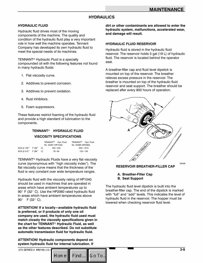
MAINTENANCE
3-9275 SERIES II MM190 (12---89)
HYDRAULICS
HYDRAULIC FLUID
Hydraulic fluid drives most of the movingcomponents of the machine. The quality andcondition of the hydraulic fluid play a very importantrole in how well the machine operates. TennantCompany has developed its own hydraulic fluid tomeet the special needs of its machines.
TENNANTr Hydraulic Fluid is a speciallycompounded oil with the following features not foundin many hydraulic fluids:
1. Flat viscosity curve.
2. Additives to prevent corrosion.
3. Additives to prevent oxidation.
4. Rust inhibitors.
5. Foam suppressors.
These features restrict foaming of the hydraulic fluidand provide a high standard of lubrication to thecomponents.
TENNANTr HYDRAULIC FLUID
VISCOSITY SPECIFICATIONSTENNANTr Hyd. Fluid TENNANTr Hyd. FluidNo. 32397 (HP1040) No. 32398 (HP2060)
SUS @ 100_ F (38_ C) 404---445 940---1010
SUS @ 210_ F (99_ C) 78---84 122---130
TENNANTr Hydraulic Fluids have a very flat viscositycurve (synonymous with “high viscosity index”). Theflat viscosity curve means that the thickness of thefluid is very constant over wide temperature ranges.
Hydraulic fluid with the viscosity rating of HP1040should be used in machines that are operated inareas which have ambient temperatures up to90_ F (32_ C). Use the HP2060 rated hydraulic fluidin areas which have ambient temperatures above90_ F (32_ C).
ATTENTION! If a locally--available hydraulic fluidis preferred, or if products of only one oilcompany are used, the hydraulic fluid used mustmatch closely the viscosity specifications given inthe chart for TENNANTr Hydraulic Fluid, as wellas the other features described. Do not substituteautomatic transmission fluid for hydraulic fluid.
ATTENTION! Hydraulic components depend onsystem hydraulic fluid for internal lubrication. If
dirt or other contaminants are allowed to enter thehydraulic system, malfunctions, accelerated wear,and damage will result.
HYDRAULIC FLUID RESERVOIR
Hydraulic fluid is stored in the hydraulic fluidreservoir. The reservoir holds 5 gal (19 L) of hydraulicfluid. The reservoir is located behind the operatorseat.
A breather-filler cap and fluid level dipstick ismounted on top of the reservoir. The breatherrelieves excess pressure in the reservoir. Thebreather is mounted on top of the hydraulic fluidreservoir and seat support. The breather should bereplaced after every 800 hours of operation.
A
B
02458
RESERVOIR BREATHER-FILLER CAP
A. Breather-Filler CapB. Seat Support
The hydraulic fluid level dipstick is built into thebreather-filler cap. The end of the dipstick is markedwith “full” and “add” levels. This indicates the level ofhydraulic fluid in the reservoir. The hopper must belowered when checking reservoir fluid level.

MAINTENANCE
3-10 275 SERIES II MM190 (12---89)
Check the hydraulic fluid level after every100 hours of operation. It should be above the “add”marks on the dipstick, but not above the “full” markwhen the hydraulic fluid is warm.
Do not overfill the hydraulic fluid reservoir. Hydraulicfluid expands as it heats to its normal operatingtemperature. Always allow for expansion when fillingthe reservoir.
ATTENTION! Do not overfill the hydraulic fluidreservoir or operate the machine with a low levelof hydraulic fluid in the reservoir. Damage to themachine hydraulic system may result.
Drain and refill the hydraulic fluid reservoir withhydraulic fluid after every 400 hours of operation.
The hydraulic system is kept clean to a level of10 microns by a hydraulic fluid filter. The hydraulicfluid filter is located under the radiator. Replace thefilter element after every 400 hours of operation.
A reservoir outlet strainer is built into the reservoir tofilter hydraulic fluid before it enters the system.Replace the strainer after every 800 hours ofoperation.
TO DRAIN HYDRAULIC FLUID RESERVOIR ANDREPLACE FILTER ELEMENT
1. Stop the engine and set the machine parkingbrake.
FOR SAFETY: Before leaving or servicingmachine; stop on level surface, set parking brake,and turn off machine.
2. Allow the hydraulic fluid to cool.
3. Unthread and discard the hydraulic fluid filterelement. Hydraulic fluid will drain through thefilter head. Discard the used hydraulic fluid.
A
B04623
HYDRAULIC FLUID FILTER
A. Filter ElementB. Machine Frame
NOTE: Be aware the hydraulic filter is lower than thereservoir. All fluid will drain from the reservoir.Discard all hydraulic fluid drained from the system. Itmay contain foreign material harmful to the hydraulicsystem.
4. Apply a thin coat of hydraulic fluid to the seal ofthe new hydraulic fluid filter element.
5. Thread and hand tighten the new hydraulicfluid filter element on the filter head.
6. Operate the machine and check for leaks.Correct any leaks found.
7. Check the hydraulic fluid reservoir level and fillas required.

MAINTENANCE
3-11275 SERIES II MM190 (12---89)
TO FILL HYDRAULIC FLUID RESERVOIR
1. Remove the reservoir breather-filler cap.
2. Pour new, approved hydraulic fluid through a200 mesh screened funnel and into thereservoir filler neck.
ATTENTION! Use only new, approved hydraulicfluid to fill the hydraulic fluid reservoir. Do notoverfill.
3. Check the hydraulic fluid level in the reservoirwith the reservoir dipstick.
4. Add hydraulic fluid until the level in the reservoiris between the “add” and the “full” range. Donot overfill.
NOTE: Do not overfill the hydraulic fluid reservoir. Ashydraulic fluid heats to its normal operatingtemperature, it expands. Always allow for thisexpansion when filling the hydraulic fluid reservoir.
5. Place the reservoir breather-filler cap securelyon the reservoir filler neck.
6. Start engine and operate all of the hydrauliccomponents. Then recheck the hydraulic fluidlevel.
HYDRAULIC PUMPS
The machine propelling pump is a variabledisplacement hydraulic piston pump. It is driven bythe engine via a chain coupling.
The machine accessories pump is a hydraulic gearpump. It is tandem mounted to the hydraulic pistonpump.
After repairing or replacing a hydraulic pump, orwhen system contamination is likely, change thehydraulic fluid in the reservoir and the hydraulic fluidfilter.
DIRECTIONAL PEDAL
The directional pedal controls the flow of hydraulicfluid to the hydraulic drive motor. The pedal hasthree positions--- ---“forward,” “neutral,” and“reverse.” The “forward” and “reverse” positionssend hydraulic fluid to the drive motor to propel themachine.
The “neutral” position is the position in which thepropelling pump sends no hydraulic fluid to thepropelling motor. The machine should not creepwhen the pedal “neutral” position is correctlyadjusted. Adjust the pedal linkages, as described inTO ADJUST DIRECTIONAL PEDAL, whenever themachine creeps or after replacing the hydraulicpropelling pump or pump linkages. The pedallinkages should also be adjusted whenever thereverse speed seems excessive or inadequate.

MAINTENANCE
3-12 275 SERIES II MM190 (12---89)
TO ADJUST DIRECTIONAL PEDAL
1. Stop the engine and set the machine parkingbrake.
FOR SAFETY: Before leaving or servicingmachine; stop on level surface, set parking brake,and turn off machine.
2. Block the machine tires and jack up the rear ofthe machine at the designated location.
WARNING: Machine is unstable on jack.Jack machine up at designated locations
only. Block machine up with jack stands.
3. Block up the machine with jack stands in thedesignated locations. Make sure the rear tireclears the floor by 2 in (50 mm) and allobstacles within a 24 in (610 mm) radius.
4. Loosen the centering spring bracketadjustment bolt jam nuts.
A
B
C
D
02486
CENTERING SPRINGS
A. Centering SpringsB. Adjustment BoltC. Spring BracketD. Jam Nut
5. Start the engine.
6. Move the directional pedal into the “forward”position and release it. The rear wheel shouldstop rotating as soon as the pedal is released.Stop the engine and adjust the spring bracketas required.
7. Move the directional pedal into the “reverse”position and release it. The rear wheel shouldstop rotating as soon as the pedal is released.Stop the engine and adjust the spring bracketas required.
8. Tighten the jam nuts.
9. Adjust the directional pedal linkage so it willcontact the lintel when the directional pedal ispressed backward. The backward travel of thepedal should be restricted so the machine willnot travel faster than 3.5 mph (5.6 km/h) withthe throttle lever in the (Fast 1) position, and4.5 mph (7.2 km/h) with the throttle lever in the(Fast 2) position in reverse. Adjust the pedallinkage connected to the pedal for pedalposition. Adjust the pump linkage next to theengine for reverse speed control.
A
B
02483
DIRECTIONAL PEDAL LINKAGE
A. Ball JointB. Pump Linkage
10. Tighten the linkage ball joints and jam nuts.
11. Raise the rear of the machine, remove the jackstands, and lower the machine.

MAINTENANCE
3-13275 SERIES II MM190 (12---89)
LIFT ARM SPEED LIMITER
The lift arm speed limiter is present on multi-leveldump model machines. It limits the forward speedthe machine can travel when the hopper is raised.The speed limiter should be adjusted whenever thepump linkage is adjusted. The machine should nottravel more than 2 mph (3.2 km/h) with the hopperraised.
The speed limiter consists of a roller bearing which ismounted on the directional linkage, and a cam onthe lift arm. When the hopper is raised, the lift armturns placing the cam under the roller bearing. Thislimits how far the directional pedal can be pressed,limiting the machine speed.
To adjust the maximum limited speed, loosen theroller bearing nut, reposition the roller bearing in itsmounting slot and tighten the nut.
A
B CD
02483
SPEED LIMITER BEARING
A. Speed Limiter BearingB. Retaining NutC. Pump LinkageD. Lift Arm Cam
HYDRAULIC FLUID LEAKS
Fluid escaping at high pressure from a very smallhole can be almost invisible and can cause seriousinjuries. Use a piece of cardboard or wood, ratherthan hands, to search for suspected leaks.
A
B
C
00002
HYDRAULIC PINHOLE LEAK
A. CardboardB. Pinhole LeakC. Magnifying Glass
If injured by escaping hydraulic fluid, see a doctor atonce. Serious infection or reaction can develop ifproper medical treatment is not administeredimmediately.
WARNING: Leaking hydraulic fluid underpressure can penetrate skin. Severe
infection or death can result. Do not use body tolocate leak. Use cardboard to locate leak.

MAINTENANCE
3-14 275 SERIES II MM190 (12---89)
04644
HYDRAULIC SCHEMATIC, LOW DUMP MODEL

MAINTENANCE
3-15275 SERIES II MM190 (12---89)
04645
HYDRAULIC SCHEMATIC, MULTI-LEVEL DUMP MODEL

MAINTENANCE
3-16 275 SERIES II MM190 (12---89)
HYDRAULIC SYSTEM TROUBLESHOOTING
Problem Cause RemedyMachine travels slowly or not Parking brake engaged Release parking brakeat all
Linkage broken or Replace and/or adjustnot adjusted properly linkageRelief valve stuck open --- (leaking) Replace relief valve
one forward, one reverseMotor failure See HYDRAULIC COMPONENTS
TROUBLESHOOTING: Hydraulicmotor failure
Pump failure See HYDRAULIC COMPONENTSTROUBLESHOOTING: Hydraulicpiston pump failure
Hydraulic fluid level low Fill hydraulic fluid reservoirMain brush does not turn Circuit breaker CB---3 tripped Reset circuit breaker
Electric on---off switch S---4 failure Replace switchHydraulic valve failure See HYDRAULIC COMPONENTS
TROUBLESHOOTING: Solenoidvalve failure
Hydraulic motor failure See HYDRAULIC COMPONENTSTROUBLESHOOTING: Hydraulicmotor failure
Gear pump failure See HYDRAULIC COMPONENTSTROUBLESHOOTING: Hydraulicgear pump
Electric lift arm switch S---9 failure Adjust or replace switchThermo Sentryt tripped Reset or replace
Thermo SentrytRelief valve stuck open --- (leaking) Replace relief valve
Side brush turns slowly Hydraulic valve failure See HYDRAULIC COMPONENTSor not at all TROUBLESHOOTING: Hydraulic
control valve failureHydraulic motor failure See HYDRAULIC COMPONENTS
TROUBLESHOOTING: Hydraulicmotor failure
Relief valve in Clean or replace reliefvalve sticking valveGear pump failure See HYDRAULIC COMPONENTS
TROUBLESHOOTING: Hydraulicgear pump

MAINTENANCE
3-17275 SERIES II MM190 (12---89)
Problem Cause RemedyPoor or no vacuum to Circuit breaker CB---3 tripped Reset circuit breakerbrush compartment Electric on-off switch S---4 failure Replace switch
Hydraulic valve failure See HYDRAULIC COMPONENTSTROUBLESHOOTING: Hydrauliccontrol valve failure
Hydraulic motor failure See HYDRAULIC COMPONENTSTROUBLESHOOTING: Hydraulicmotor failure
Gear pump failure See HYDRAULIC COMPONENTSTROUBLESHOOTING: Hydraulicgear pump
Electric lift arm switch S---9 failure Adjust or replace switchThermo Sentryt tripped Reset or replace
Thermo SentrytRelief valve stuck open --- (leaking) Replace relief valve
Hopper will not lift Hydraulic valve See HYDRAULIC COMPONENTSfailure TROUBLESHOOTING: Hydraulic
control valve failureHydraulic orifice at lift Replace orificecylinder pluggedLift cylinder failure See HYDRAULIC COMPONENTS
TROUBLESHOOTING: Hydrauliccylinder failure
Hopper overloaded Empty hopperLift arms binding Replace and/or adjust
lift arm linkageGear pump failure See HYDRAULIC COMPONENTS
TROUBLESHOOTING: Hydraulicgear pump
Hopper will not lower Lift cylinder failure See HYDRAULIC COMPONENTSTROUBLESHOOTING: Hydrauliccylinder failure
Lift arms binding Replace and/or adjustlift arm linkage
Hopper will not roll out Hydraulic valve See HYDRAULIC COMPONENTSfailure TROUBLESHOOTING: Hydraulic
control valve failureDump cylinder failure See HYDRAULIC COMPONENTS
TROUBLESHOOTING: Hydrauliccylinder failure
Gear pump failure See HYDRAULIC COMPONENTSTROUBLESHOOTING: Hydraulicgear pump
Lift arms binding Replace and/or adjustlift arm linkage

MAINTENANCE
3-18 275 SERIES II MM190 (12---89)
HYDRAULIC COMPONENTS TROUBLESHOOTINGProblem Cause RemedyHydraulic cylinder failure Piston seals leaking Install seal kit
Barrel worn or rod bent Replace cylinderHydraulic control valve Valve seals leaking Install seal kitfailure Relief valve stuck open Clean or replace relief valve
(leaking) cartridgeSolenoid valve failure Valve leaking Install seal kit
Solenoid failure Replace solenoid coilSolenoid spool sticking Replace valve cartridgeRelief valve stuck Clean or replace reliefopen (leaking) valve cartridge
Hydraulic motor failure Motor leaking Install seal kitDrive link failure Replace drive linkGerotor worn Replace gerotor setOutput shaft failure Replace output shaft and
bearingsHydraulic gear pump Pump leaking Install seal kitfailure Gear set failure Replace gear set
Shaft failure Replace gear setFlow divider failure Replace back plate assemblyEngine-to-pump coupling Replace couplingfailure
Hydraulic piston pump Pump leaking Install seal kitfailure Relief valve stuck Clean or replace relief valve
Integral charge pump failure Replace charge pumpRotating group worn Replace rotating groupShaft failure Replace shaftBackplate worn Replace backplateEngine-to-pump coupling Replace couplingfailure

MAINTENANCE
3-19275 SERIES II MM190 (12---89)
ENGINE
ENGINE LUBRICATION
Check the engine oil level daily. Change the engineoil and oil filter after every 50 hours of operation.
GASOLINE AND LPG POWERED ENGINES
Gasoline and LPG powered engines should belubricated with SAE---SE/SF rated engine oil.
The following oil grades are recommended forengines during changing seasonal temperatures:
MULTI---VISCOSITY OILSBelow 32_F ---10_ to 90_F ---10_ to 90_F Above 10_F(Below 0_C) (---23_ to 32_C) (---23_ to 32_C) (Above---12_C)
5W 30 10W 30 10W 40 20W 40
SINGLE VISCOSITY OILS---10_ to 32_F 10_ to 60_F 32_ to 90_F Above 60_F(---23_ to 0_C) (---12_ to 16_C) (0_ to 32_C) (Above 16_C)
10W 20W 20 30 40
The engine oil capacity is 3.5 qt (3.3 L) including theoil filter.
DIESEL POWERED ENGINES
Diesel powered engines should be lubricated withSAE---CC/CD rated engine oil.
The following oil grades are recommended forengines operating in the ambient temperatureslisted.
SINGLE AND MULTI---VISCOSITY OILSBelow 32_F 32_ to 77_ F Above 77_ F(Below 0_C) (0_ to 25_ C) (Above 25_ C)
10W 20 3010W 30
The engine oil capacity is 7 qt (6.7 L) including the oilfilter.
COOLING SYSTEM
Maintaining cooling system efficiency is important.Engine temperatures must be brought up to andmaintained within the satisfactory range for efficientoperation. However, the engine must be kept fromoverheating in order to prevent damage to thevalves, pistons, and bearings. Check the radiatorcoolant level after every 100 hours of operation.
Use soft, clean water mixed with permanent--- type,ethylene glycol antifreeze in a one-to-one ratio to fillthe cooling system. Deposits of sludge, scale, andrust prevent normal heat transfer. Flush the radiatorand the cooling system after every800 hours of operation, with a cleaning compound.
Follow the mixing procedure recommended by thecompound manufacturer. This is important becauseof the difference in concentration and composition ofthe cleaning compounds. After cleaning, flush thesystem with clean water.
Whenever a cooling system is badly rust-clogged, asindicated by overflow loss or abnormally highoperating temperatures, corrective cleaning byreverse flow flushing will most effectively remove theheavy deposits of sludge, rust, and scale. Thereverse flow flushing should be performedimmediately after draining the cleaning solution.Flush the radiator first, then the engine, to allow theengine to cool as much as possible.
Engine overheating may also be caused by dirtyradiator fins. The exterior fins of the radiator can becleaned with an air or water hose. Check the radiatorcore exterior daily for debris.
WARNING: Air or water under pressure.Severe eye or ear injury can result. Wear
eye and ear protection.
Blow or rinse all dust, which may have collected onthe radiator, in through the grill and radiator fins,opposite the direction of normal air flow. The grill andhydraulic cooler may be tilted back for easiercleaning. Use care not to bend the cooling fins whencleaning. Clean thoroughly to prevent caking dust.Clean the radiator and cooler only after the radiatorhas cooled to avoid cracking.
A
B
C
02468
RADIATOR ACCESS
A. RadiatorB. Hydraulic Fluid Cooler

MAINTENANCE
3-20 275 SERIES II MM190 (12---89)
C. Retainer
The engine is equipped with a 180_ F (82_ C)thermostat. Normal engine temperature is 200_ F(93_C). Temperatures up to 220_ F (104_ C) areallowable. Temperatures over 220_ F (104_ C)indicate a problem exists.
A pressure cap is used on the radiator to preventoverflow loss of water during normal operation. Thespring-loaded valve in the cap closes the outlet tothe overflow pipe of the radiator and thus seals thesystem. Pressure developing within the systemraises the boiling point of the coolant and allowshigher temperatures without overflow loss fromboiling. The pressure valve opens at 7 psi (50 kPa),allowing steam and water to pass out the overflowpipe.
WARNING: Hot engine coolant. Scaldingcan result. Do not open radiator cap or
service cooling system until radiator and engineis cool to the touch.
ATTENTION! Never pour cold water or coldantifreeze into the radiator of an overheatedengine. Allow the engine to cool to avoid crackingthe cylinder head or block. Keep the enginerunning while adding water.
AIR INTAKE SYSTEM
The importance of maintaining an air filter cannot beoveremphasized. Dirt ingested through improperlyinstalled, improperly serviced, or inadequate air filterelements wears out more engines than long hours ofoperation. Even a small amount of dirt will wear out aset of piston rings in just a few hours. Operating witha clogged air filter element also causes the fuelmixture to be richer, which can lead to formation ofharmful sludge deposits in the engine. Always coverthe air intake when the air filter is removed forservicing. Do not neglect servicing the air filter. Useonly approved replacement parts. Keep all other airintake components secure and in good condition toprevent entrance of unfiltered air.
Overmaintenance can cause more damage thangood. Removing the air filter element more oftenthan is needed allows contaminants to enter theengine unnecessarily. Clean or replace the air filterelement only when the restriction indicator indicatesexcessive restriction in the system.
AIR FILTER RESTRICTION INDICATOR
The air filter restriction indicator signals when toclean or replace the air filter element. Check therestriction indicator daily. The yellow indicatorgradually becomes visible as the air filter elementloads with dirt.
Do not clean or replace the air filter element until theyellow indicator reaches the top of the serviceindicator and reads 20 in (500 mm). The indicatormay return to the “no restriction” position when theengine is shut off. It will return to the “visible”position when the engine is started.
Clean or replace the filter element when the yellowindicator reads 20 in (500 mm). After cleaning orreplacing the air filter element, reset the serviceindicator by pushing the “reset” button on the end ofthe indicator.
A
B
C
02172
AIR FILTER RESTRICTION INDICATOR
A. Restriction IndicatorB. Indicator WindowC. Indicator Reset Button

MAINTENANCE
3-21275 SERIES II MM190 (12---89)
AIR FILTER
The engine air filter housing includes a dust cap anda dry cartridge---type air filter element. The dust capmust be emptied of dirt daily. The air filter elementmust be cleaned and inspected or replacedwhenever the yellow indicator of the air filterrestriction indicator reads 20 in (500 mm). The filterelement must be replaced if it is damaged or hasbeen cleaned three times.
Machines with the heavy duty air filter accessoryhave a safety element. It is located inside of thestandard element. This element should be replaced,not cleaned after the regular element has beendamaged or has been serviced three times.
Service the air filter element only when the restrictionindicator indicates excessive restriction in thesystem. Do not remove the air filter element unless itis restricting air flow.
TO REPLACE AIR FILTER ELEMENT
1. Stop the engine and set the machine parkingbrake.
FOR SAFETY: Before leaving or servicingmachine; stop on level surface, set parking brake,and turn off machine.
2. Open the left side and top engine accessdoors.
3. Unscrew the clamp ring on the filter.
4. Remove the dust cap.
5. Empty the dust cap.
6. Remove the filter wing nut.
7. Gently pull the filter element out of the filterhousing.
A
B
C
D
E
F
02173
REMOVING AIR FILTER ELEMENT
A. Filter HousingB. Clamp RingC. Filter ElementD. Safety Air Filter Element (Accessory)E. Dust CapF. Wing Nut
8. Clean the interior of the air cleaner housing witha damp cloth. Clean the element housingsealing surfaces.

MAINTENANCE
3-22 275 SERIES II MM190 (12---89)
9. Using an air hose, direct dry, clean airmaximum 30 psi (205 kPa) up and down pleatson the inside of the filter. Do not rap, tap, orpound dust out of the element.
WARNING: Air or water under pressure.Severe eye or ear injury can result. Wear
eye and ear protection.
A
B
00051
CLEANING AIR FILTER ELEMENT
A. Air HoseB. Filter Element
10. After cleaning the air filter element, inspect it fordamage by placing a bright light inside. Theslightest rupture requires replacement of thefilter. Clean and inspect the seals on the endsof the element. They should be unbroken andflexible. Remember, the element must bereplaced after it has been cleaned three times.
A
B
03500
INSPECTING AIR FILTER ELEMENT
A. Bright LightB. Filter Element
11. Install the new or cleaned filter element so thefins on the element are at the intake end of theair cleaner. Use care so the fins are notdamaged. Make sure the element is seatingevenly. Tighten the element wing nut.
12. Install the dust cap with the arrows pointing up.Tighten the clamp ring to hold it in place.Check all intake hose connections for leaks orabrasion.
A
02492
DUST CAP
A. Dust Cap
13. Reset the air filter restriction indicator.
14. Close the access doors.

MAINTENANCE
3-23275 SERIES II MM190 (12---89)
FUEL SYSTEM -- GASOLINE
FUEL FILTER
The fuel filter traps fuel impurities. It is located belowthe air filter. Replace the filter element as required.
CARBURETOR
The carburetor has two basic adjustments. Thoseadjustments are idle fuel mixture and idle speed.Check and adjust idle fuel mixture and idle speedafter every 400 hours of operation. The idle fuelmixture is controlled by a screw located on the frontof the carburetor. Turning the screw in, clockwise,leans the fuel mixture. Turning the screwcounter-clockwise, richens the fuel mixture.
The idle speed is controlled by a screw located onthe side of the carburetor next to the throttle linkage.Turning the screw clockwise increases enginespeed. Turning the screw out, counterclockwise,decreases engine speed. Proper idle speed is 950 +50 rpm with all accessories in the “off” position.
WARNING: Fuel vapor is present whenservicing fuel system. Fire or explosion can
result. Keep flames and sparks away.
FUEL SYSTEM -- LPG
LPG FUEL SYSTEM
The liquid withdrawal LPG fuel system is made up offive components which are: the LPG fuel tank,pressure relief valve, fuel filter lock,vaporizer-regulator, and the carburetor.
Liquid LPG fuel flows from the LPG tank, under itsown pressure, to the pressure relief valve. This valveis normally closed, preventing LPG fuel fromescaping into the atmosphere. The valve opens torelieve pressure if the fuel pressure exceeds systemlimits. From the pressure relief valve, the liquid LPGfuel is piped to the fuel filter lock.
The fuel filter lock filters unwanted tank scale anddeposits out of the LPG fuel. The fuel filter lock alsostops the flow of LPG fuel when the engine is notoperating. The oil pressure switch controls the fuelfilter lock. When the engine oil pressure is5 psi (35 kPa) or greater, the oil pressure switchpermits an electrical current to open the fuel filterlock which allows LPG fuel to flow on to thevaporizer-regulator. The oil pressure switch isbypassed when the engine is being started, allowingLPG fuel to flow.
The vaporizer section of the vaporizer-regulatorconverts the liquid LPG fuel into a gaseous LPG fuel.From the vaporizer section, the gaseous LPG fuel issent to the primary regulator section of thevaporizer-regulator. The primary regulator sectionreduces the pressure of the LPG fuel. The secondaryregulator section reduces the LPG fuel pressure tothe level required by the carburetor. From thevaporizer-regulator, the LPG fuel is sent to thecarburetor where it is finally metered into the air flowwhich is sent to the engine combustion chamber.

MAINTENANCE
3-24 275 SERIES II MM190 (12---89)
A B
C
D
F
G
E
03511
LPG FUEL SYSTEM
A. CarburetorB. Vaporizer-RegulatorC. Fuel Filter LockD. Pressure Relief ValveE. Tank Service ValveF. LPG Fuel TankG. Oil Pressure Switch
Never operate an LPG powered machine if the LPGfuel system is leaking, or if any component in the fuelsystem is malfunctioning. Operating the machineunder either of these conditions may cause a fire orexplosion.
Check for frosting. Frosting does occur before theengine reaches operating temperature. Check afterengine reaches operating temperature. If frostingoccurs on or near any LPG component, there is apossibility of an LPG fuel leak or a malfunctioningcomponent.
To locate the leak, apply a soapy water solution tothe suspected area. Watch for bubbles forming in aconfined area. This area may have an LPG fuel leak.Repair or replace the part. Use Loctite brandStainless Steel PST thread sealant whenreassembling. This epoxy--- type sealant is notaffected by aging or high humidity. Be sure to followapplication directions and apply proper torque whenreconnecting fittings.
Never bypass safety components except to test. Ifthey are defective, replace them before operating themachine.
Check routings of all LPG hoses. Keep them awayfrom sharp edges, exhaust manifolds, or other hotsurfaces. Check for signs of abrasion ordeterioration. Replace hoses found to be worn ordamaged.
FUEL TANKS
The LPG fuel tanks should be inspected for sharpdents, gouges, leaks, and broken protecting ringswhenever the tanks are refilled. All tank valves mustbe inspected for leaks using a soap solution. Valvesmust also be checked for dirt, paint, or other debrisin the valve openings. The following specific checksmust also be made:
Filler Valve --- Check for proper functioning and thepresence of the handwheel. Valve must be closedexcept during filling.
Vapor and Liquid Service Valves --- Check for properfunctioning and presence of the handwheel. Thevalve must be closed except when in service.
Tank Service Valve Coupling --- Check for properfunctioning, thread condition, and damaged ormissing washers or o-rings.
Safety Relief Valve --- Check for damage. Check forthe presence of the relief valve elbow and the properdirection of the elbow. If the rain cap is missing,check for foreign matter and replace cap. Do nottamper with the relief valve setting.
Liquid Level Gauge --- Check operation against themaximum filling point as determined by weight.
AB
C
D
E
03485
TYPICAL LPG LIQUID WITHDRAWAL FUEL TANK
A. Filler ValveB. Safety Relief ValveC. Liquid Service ValveD. Service Valve CouplingE. Liquid Level Gauge
An LPG fuel tank with any of the stated defects mustbe removed from service and be repaired ordestroyed accordingly.

MAINTENANCE
3-25275 SERIES II MM190 (12---89)
If an LPG fuel tank is damaged or leaking, it shouldbe removed to a designated safe area, and theproper personnel should be notified. Do not attemptto make repairs to the tank, regardless of condition.Repairs or disposal must only be made by qualifiedpersonnel.
The care an LPG fuel tank receives has a directbearing on how long that tank can be used safely.LPG fuel tanks must not be dropped or draggedacross any surface. To move LPG fuel tanks, use ahand truck or roll the tank on its foot ring while it isbeing held in a position slightly off vertical.
Whether the storage is inside or outside, fuel tanksshould not be stored in the vicinity of combustiblematerials or high temperature sources such as ovensand furnaces, since the heat may raise the pressureof the fuel to a point where the safety relief valveswould function. Care should be taken to insure thatthe tanks are stored in such a manner that if thesafety relief valves do function, they will relieve vapor,rather than liquid.
Valves on empty tanks must be closed duringstorage and transportation.
Similar precautions should be taken in storingmachines fitted with LPG fuel tanks. They may bestored or serviced inside buildings, provided thereare no leaks in the fuel system and the tanks are notoverfilled. While machines are being repaired insidea building, the shut-off valve on the tank must beclosed, except when the engine must be operated.
The tank changing operation presents anopportunity for the machine operator to carefullyobserve the tank, fittings, and the fuel lines andfittings for his own satisfaction. If abnormal wear isdetected, the operator should report it to theappropriate personnel for action.
TO CHANGE AN LPG FUEL TANK
1. Park the machine in a designated safe area.
WARNING: Fuel vapor is present whenservicing fuel system. Fire or explosion can
result. Keep flames and sparks away.
2. Close the tank service valve.
3. Operate the engine until it stops from lack offuel, then set the machine parking brake.
FOR SAFETY: Before leaving or servicingmachine; stop on level surface, set parking brake,and turn off machine.
4. Put on gloves and remove the quick-disconnecttank coupling.
WARNING: LPG fuel is very cold. Frostbitecan result. Wear gloves when connecting or
disconnecting LPG hoses.
5. Inspect the LPG fuel lines for wear or damage.
6. Remove the empty LPG fuel tank from themachine.
7. Check the tank for damage or wear.
8. Store the tank in a designated safe area.
9. Select a filled LPG fuel tank and inspect it fordamage or leaks.
NOTE: Make sure the LPG fuel tank matches the fuelsystem (liquid tank with liquid system).
10. Carefully place the LPG tank in the machine sothat the tank centering pin enters the aligninghole in the tank collar.
NOTE: If the pin cannot be engaged, make sure youhave the correct LPG fuel tank and then adjust the pinlocator in or out.
11. Fasten the tank hold-down clamp to lock thetank in position.

MAINTENANCE
3-26 275 SERIES II MM190 (12---89)
12. Connect the LPG fuel line to the tank servicecoupling. Make sure the service coupling isclean and free of damage. Also make sure itmatches the machine service coupling.
13. Open the tank service valve slowly and checkfor leaks. If an LPG leak is found, close theservice valve immediately and notify theappropriate personnel.
14. If no leaks are found, the engine is ready tostart.
FUEL FILTER LOCK
The fuel filter lock filters the LPG fuel. It also stopsthe flow of LPG fuel to the engine when the engine isnot operating or when the engine oil pressure is lessthan 5 psi (35 kPa).
Replace the filter pack with the filter packreplacement kit if diminished gas flow indicates thefilter is clogged. A drain plug is provided for purgingthe filter bowl. Clean out the bowl when replacing thefilter pack.
VAPORIZER-REGULATOR
If any malfunction is noted, completely disassemblethe vaporizer-regulator. Clean all of the parts inalcohol. Inspect all of the parts and replace whereneeded. Carefully reassemble the vaporizer-regulatorwith the seal repair kit. Check for proper operation.
CARBURETOR
If any malfunction is noted, completely disassemblethe carburetor. Clean all of the parts in alcohol.
Inspect all of the parts and replace when needed.Carefully reassemble the carburetor with the sealrepair kit.
OIL PRESSURE SWITCH
The engine oil pressure switch requires no regularmaintenance. Never bypass the oil pressure switchas this is a safety feature which prevents LPG fuelfrom flowing when the engine is not operatingproperly.

MAINTENANCE
3-27275 SERIES II MM190 (12---89)
LPG FUEL TROUBLESHOOTING
Problem Cause RemedyEngine will not start Out of fuel Replace fuel tank with full one
Service valve opened too Close valve and reopen slowlyquickly --- engaging safety valvePlugged fuel filter Replace filterKinked or restricted fuel Straighten or replace fuel linelineEngine out of tune Tune-up engineOil pressure switch failure Replace oil pressure switchFuel lock valve failure Repair or replace fuel filter lockVaporizer---regulator failure Repair or replace
vaporizer-regulatorEngine runs unevenly Wrong type of fuel Replace vapor withdrawal tankor lacks power tank --- vapor withdrawal tank with liquid withdrawal tank
Plugged fuel filter Replace filterKinked or restricted fuel line Straighten or replace fuel lineEngine out of tune Tune-up engineRestricted air filter Clean or replace air filter
elementVaporizer---regulator maladjusted Adjust vaporizer-regulator

MAINTENANCE
3-28 275 SERIES II MM190 (12---89)
FUEL SYSTEM -- DIESEL
DIESEL FUEL SYSTEM
The diesel fuel system is made up of five basiccomponents which are: fuel tank, fuel watertrap-filter, fuel pump, injection pump, and injectors.
Fuel flows from the fuel tank through the fuel watertrap-filter. The water trap-filter separates water andimpurities from the fuel. From the fuel water trap-filter,fuel is drawn through the electric fuel pump andpumped to the injection pump. The injection pumppressurizes and sends fuel to the injectors. Theinjectors atomize and inject proper amounts of fuelinto the combustion chamber at the proper times.Excess fuel is returned to the fuel tank through anoverflow pipe.
FUEL WATER TRAP-FILTER
The fuel water trap-filter separates water andimpurities from the fuel. It is located next to theengine bellhousing. The bottom portion of the unit isthe water trap. The middle portion is the filterelement.
Drain the water trap of water daily. To drain the watertrap, loosen the drain knob on the bottom of the unit.First water, then diesel fuel will drain. Tighten thedrain knob when diesel fuel appears.
Replace the fuel filter element and clean the watertrap after every 400 hours of operation.
TO REPLACE FUEL FILTER ELEMENT
1. Stop the engine and set the machine parkingbrake.
FOR SAFETY: Before leaving or servicingmachine; stop on level surface, set parking brake,and turn off machine.
2. Open the side and top engine access doors.
3. Loosen the unit vent plug and open the watertrap drain to drain diesel fuel.
AB
C
D
02765
FUEL WATER TRAP-FILTER
A. Filter HeadB. Vent PlugC. Filter ElementD. Water Trap Bowl
4. Remove the filter element and the water trapfrom the filter head.
5. Remove the water trap bowl from the filterelement.
6. Clean the water trap bowl.
7. Lubricate the o-ring and spin the water trapbowl onto the new filter element.
8. Lubricate the o-ring and spin the filter elementand water trap onto the filter head.
9. Bleed the fuel lines of air as described in TOPRIME FUEL SYSTEM.
10. Close the side and top engine access doors.

MAINTENANCE
3-29275 SERIES II MM190 (12---89)
PRIMING FUEL SYSTEM
Priming the fuel system removes pockets of air in thefuel lines and fuel components. Air in the fuel systemwill prevent smooth engine operation.
Prime the fuel system after running out of fuel,changing fuel filter elements or repairing a fuelsystem component.
TO PRIME FUEL SYSTEM
1. Stop the engine and set the machine parkingbrake.
FOR SAFETY: Before leaving or servicingmachine; stop on level surface, set parking brake,and turn off machine.
2. Fill the fuel tank.
3. Open the side and top engine access doors.
4. Open the air vent on top of the fuel injectionpump.
A
B
02766
FUEL INJECTION PUMP
A. Injection PumpB. Air Vent
5. Start the engine, operate it for one minute, thenstop it; or operate the starter motor inten---second intervals until a steady stream offuel flows from the vent.
6. Close the air vent.
7. Close the access doors.
GOVERNOR -- GASOLINE, LPG (For machinesbelow serial number 006500)
The governor controls engine speed. It is driven by abelt which spans the crankshaft sheave.
The governor is oil filled. It requires no regularinspections. Change the oil when performing majorengine work. Use an SAE rated 10W30 or 10W40engine oil.
A
B
C
D
E F
GH
02460
GOVERNOR
A. High Speed Stop ScrewB. Oil Fill PlugC. Low Speed Stop ScrewD. GovernorE. Oil Level PlugF. Surge ScrewG. Regulation ScrewH. Throttle Rod
The governor is factory set and should not beadjusted unless the engine speed varies from thespecification or if the engine surges. The governorshould be set so the engine operates at2200 + 50 rpm at “normal” speed setting under loadand at 2650 + 50 at “litter” speed setting under load.A surge screw has been provided to compensate forsurging --- --- adjust it with care or governor damagemay result. The regulation screw has been factoryset and should not be tampered with.
TO ADJUST GOVERNOR (For machines below serialnumber 006500)
1. Operate the engine until it reaches normaloperating temperature.

MAINTENANCE
3-30 275 SERIES II MM190 (NIL)
2. Park on a level surface, stop the engine, andset the machine parking brake.
FOR SAFETY: Before leaving or servicingmachine; stop on level surface, set parking brake,and turn off machine.
3. Check the governor belt tension as describedin GOVERNOR BELT.
4. Place the throttle lever in the “normal” or (Fast1) position. There should be a 0.03 to 0.06 in (1to 2 mm) space between the carburetor leverand the lever stop. Adjust the throttle rod asrequired.
5. Move the throttle lever to the (Idle) position.Start the engine and adjust the engine idlespeed screw so the engine operates at 950 +50 rpm.
6. Place the throttle lever in the “litter” or(Fast 2) position. Turn the side brush and mainbrushes on, and adjust the high speed stopscrew so the engine operates at 2600 rpm.Then adjust the surge screw so the engineoperates at 2650 rpm. Tighten all lock nuts.
FOR SAFETY: Before leaving or servicingmachine; stop on level surface, set parking brake,and turn off machine.
7. Place the throttle lever in the “normal” or (Fast1) position. Adjust the low speed stop screw sothe engine operates at 2200 +50 rpm.
8. Stop the engine.
9. Check and adjust the throttle cable positionand the throttle lever stops to allow full linkagemovement.
GOVERNOR -- GASOLINE, LPG (For machinesserial number 006500 and above)
The electronic governor controls engine speed. Thegovernor consists of an ignition control assemblyand control box located in front of the engine aircleaner,and an actuator mounted on the engine. Theignition control box regulates the actuator, which inturn controls the throttle.
The electronic governor is factory set and is not userserviceable.
IGNITION SYSTEM -- GASOLINE, LPG
SPARK PLUGS
Clean or replace and adjust spark plugs after every400 hours of operation. Spark plug gaps are bestchecked with a wire gauge unless the plug isdressed to obtain a correct reading with a flat gauge.The adjustment should always be made on the sideelectrode and never on the center electrode, whichmay cause a broken porcelain.
“Gapping” the electrode tip is more easily done withthe proper tools.
AB
01471
GAPPING SPARK PLUG
A. Spark PlugB. Gapping Tool
The proper spark plug gap is 0.035 in (0.9 mm) formachines below serial number 006500. The properspark plug gap is 0.039 in (1 mm) for machinesserial number 006500 and above.
Spark plugs must be correctly installed in order toobtain good performance. It is a simple butimportant matter to follow these procedures wheninstalling plugs:
1. Clean the spark plug seat in the cylinder head.
2. Use a new seat gasket and screw the plug inby hand.
3. Tighten the spark plugs to 22 to 28 ft lb(30 to 38 Nm) with a socket wrench of thecorrect size.

MAINTENANCE
3-31275 SERIES II MM190 (12---89)
DISTRIBUTOR (For machines below serial number006500)
The distributor operation is vital to the operation ofthe engine. The following items should be carefullyinspected after every 400 hours of normal operation;however, dirt, dust, water, and high speed operationmay cause more rapid wear and necessitate morefrequent inspections:
1. Remove the distributor cap. Clean the cap andexamine for cracks, carbon runners, orcorroded terminals. If the vertical faces of theinserts are burned, install a new cap. If thehorizontal faces of the inserts are burned,replace the cap and the rotor as this conditionis caused by the rotor being too short. Inspectcap to distributor seal and the distributorhousing breather.
2. Check the centrifugal advance mechanism for“freeness” by turning the breaker cam in thedirection of rotation and then releasing it. Theadvance springs should return the cam to itsoriginal position.
ENGINE IGNITION TIMING (For machines belowserial number 006500)
The engine ignition timing must be checked with atiming light, using the timing points located on thefront of the engine and the timing marks located onthe crankshaft pulley. Distributor ignition timingshould be checked after the first 50 hours ofoperation and after every 400 hours of operationthereafter.
To check and adjust the ignition timing with a scope,refer to the scope manufacturer’s instructions. Tocheck and adjust the timing with a timing light,proceed as follows:
TO CHECK AND ADJUST IGNITION TIMING (Formachines below serial number 006500)
NOTE: Dwell angle must be correct or timing will notbe accurate.
1. Stop the engine and set the machine parkingbrake.
FOR SAFETY: Before leaving or servicingmachine; stop on level surface, set parking brake,and turn off machine.
2. Clean and mark the timing marks.
NOTE: Painting a white line on the front pulley timingmarks will make them more visible under the timinglight.
3. Disconnect and plug the vacuum hose from thedistributor.
A
B00696
ENGINE TIMING MARKS
A. Timing PointerB. Crankshaft Pulley
4. Connect the timing light to the No. 1 cylinderspark plug wire. Connect a tachometer to theengine.
WARNING: Keep away from fan.
5. Start the engine and reduce the idle speed to600 rpm to be sure that the centrifugal advanceis not operating. Adjust the initial ignition timingto 6_ BTDC on gasoline engines, and 10_BTDC on LPG engines.
To advance the timing, turn the distributor bodyclockwise. To retard the timing, turn thedistributor body counterclockwise.
6. Check the centrifugal advance for properoperation by starting the engine andaccelerating it to approximately 2000 rpm. If theignition timing advances, the centrifugaladvance mechanism is functioning properly.Note the engine speed when the advancebegins and the amount of total advance. Stopthe engine.

MAINTENANCE
3-32 275 SERIES II MM190 (12---89)
7. Unplug the vacuum line and connect it to thedistributor vacuum advance unit. Start theengine and accelerate it to approximately 2000rpm. Note the engine speed when the advancebegins and the total amount of advance.Advance of the ignition timing should beginsooner and advance farther than whenchecking the centrifugal advance alone. Stopthe engine.
8. If the vacuum advance is not functioningproperly, remove the distributor and check it ona distributor tester.
9. After adjusting timing, be sure to increase theengine idle speed to its normal setting.
ENGINE IGNITION TIMING (For machines serialnumber 006500 and above)
The ignition system does not require any mechanicalexternal adjustments, however the spark plug hightension leads must be inserted correctly, if everremoved, at each numbered coil position to thecorresponding spark plug number in the cylinder(front to rear #1, 2, 3, and 4).
The ESC module controls the timing position in thestart mode at 10_ BTDC until the rpm reaches250 rpm, thereafter the sensors are processed andtiming is set to be compatible with engine speed,crankshaft position, engine load, engine coolanttemperature and overspeed by the module.
CYLINDER HEAD -- GASOLINE, LPG
CYLINDER HEAD
A three-stage torque procedure should be usedwhen reassembling the cylinder head. The cylinderhead bolts must be tightened after the first50 hours of operation, for machines below serialnumber 006500 and seasonally thereafter for allgasoline and LPG machines.
Snug down cylinder head bolts in the propersequence; first to 7 to 11 ft lb (10 to 15 Nm), then to30 to 37 ft lb (40 to 50 Nm), then to 60 to 66 ft lb (80to 90 Nm), and then after ten to fifteen minutestorque to 74 to 81 ft lb (100 to110 Nm).
Tighten the intake manifold bolts to 15 to 18 ft lb (20to 24 Nm) after every 800 hours of operation.
1
2
3
4
5
6
7
8
9
1003532
CYLINDER HEAD BOLT TIGHTENING SEQUENCE
The cylinder head bolts must be retorqued after theengine is put into operation and brought up toproper operating temperatures. To retorque headbolts, follow the correct sequence. Loosen one headbolt at a time one-quarter turn, 90 degrees; thenretorque it to the correct value.
NOTE: Power wrench torque limit must be held atleast 10 ft lb (14 Nm) below hand torquespecification; then hand torque to the specifications.
VALVE TAPPET CLEARANCE
The valve tappet clearance must be checked andadjusted if necessary after every 400 hours ofoperation.
To set the valve clearance without the engineoperating, rotate the crankshaft until No. 1 cylinder isat the top of the compression stroke. Check thetiming marks. It should read 0 or TDC. Both valveson No. 1 cylinder are now closed. Set the valveclearance on both valves. Next, rotate the crankshaft180_, and set the valve lash on both valves on No. 2cylinder. Again rotate the crankshaft 180_, and setthe valve lash on both valves on No. 4 cylinder.Rotate the crankshaft another 180_, and set thevalve lash on both valves on No. 3 cylinder.
Check and adjust, for machines below serial number006500, the intake valve clearance from 0.009 in(0.22 mm), and the exhaust valve clearance from0.023 in (0.59 mm) while the engine is cold.
Check and adjust, for machines serial number006500 and above, the intake valve clearance from0.009 in (0.22 mm), and the exhaust valve clearancefrom 0.013 in (0.32 mm) while the engine is cold.

MAINTENANCE
3-33275 SERIES II MM190 (12---89)
CYLINDER HEAD -- DIESEL
CYLINDER HEAD
The cylinder head must be properly torqued afterservicing to ensure proper operation. A three-stagetorque procedure should be used. Snug down thecylinder head bolts and nuts in the proper sequence;first to one-third, then two-thirds, and then to the fulltorque specification of 55 to 60 ft lb (75 to 80 Nm).Retighten the bolts and nuts after operating theengine for30 minutes.
NOTE: Power wrench torque limit must be held atleast 10 ft lb (15 Nm) below torque specification.Hand tighten to specification.
02767
CYLINDER HEAD BOLT TIGHTENING SEQUENCE
VALVE CLEARANCE
The valve clearance must be properly adjusted afterservicing or retorquing the cylinder head bolts toensure proper operation. Measure valve clearancewith a feeler gauge after aligning each cylinder onthe compression top dead center stroke.
Adjust them with the engine cool to 0.0071 to 0.0087in (0.18 to 0.22 mm) in the firing order 1---2---3.
CRANKCASE VENTILATION SYSTEM
Clean the crankcase ventilation hoses, tubes, andfittings and replace the PCV valve after every400 hours of operation.
TUNE-UP CHART -- GASOLINE, LPG
Idle speed, no load 950 + 50 rpm
(Fast 1) governed 2200 + 50 rpmspeed, under load
(Fast 2) governed 2650 + 50 rpmspeed, under load
Spark plug gap 0.035 in (0.9 mm)(for machines belowserial number 006500)
Spark plug gap 0.039 in (1 mm)(for machinesserial number006500 and above)
Timing 6_ BTDC @ 600 rpm,(for machines gasolinebelow serial 10_ BTDC @ 600 rpm,number 006500) LPG
Firing order 1---2---4---3,counterclockwiserotation
Valve clearance, cold 0.009 in (0.22 mm)(for machines below intakeserial number 006500) 0.023 in (0.59 mm)
exhaust
Valve clearance, cold 0.009 in (0.22 mm)(for machines serial intakenumber 006500 0.013 in (0.32 mm)and above) exhaust

MAINTENANCE
3-34 275 SERIES II MM190 (12---89)
ELECTRICAL SYSTEM
BATTERY
The battery used in the machine is a lowmaintenance battery. It has been constructed withspecial materials and has extra electrolyte to reduceor eliminate maintenance. Its design reduceselectrolyte loss and contamination. Do not add water,remove the battery vent plugs, or check the batteryspecific gravity. For specific instructions, see thebattery label.
The battery is rated at 12 V, 475 ccA. It is locatedunder the operator foot plate. When removingbattery cables, remove the negative (---) cable beforethe positive (+) cable.
A
B
00586
BATTERY
A. BatteryB. Floor Plate
Do not allow the battery to remain in dischargedcondition for any length of time. Do not operate themachine if the battery is in poor condition ordischarged beyond 80%, specific gravity below1.120.
Clean the top surface and the terminals of thebattery periodically. Use a strong solution of bakingsoda and water. Brush the solution sparingly over thebattery top, terminals, and cable clamps. Do notallow any baking soda solution to enter the battery.Use a wire brush to clean the terminal posts and thecable connectors. After cleaning, apply a coating ofclear petroleum jelly to the terminals and the cableconnectors. Keep the top of the battery clean anddry.
Keep all metallic objects off the top of the battery, asthey may cause a short circuit. Replace worn ordamaged wires.
The electrolyte level in regular nonsealed batteriescan be checked. It must always be above the batteryplates. Add distilled water to maintain solution at thecorrect level above the plates, but do not overfill.Never add acid to batteries, only water. Keep ventplugs firmly in place at all times, except when addingwater or taking hydrometer readings.
WARNING: Battery acid causes severeburns. Avoid contact. Wash immediately
and get medical attention if contact occurs.
If when checking battery specific gravity, one ormore battery cells tests lower than the other batterycells, (0.050 or more) the cell is damaged, shorted,or is about to fail.
NOTE: Do not take readings immediately after addingwater --- ---if the water and acid are not thoroughlymixed, the readings may not be accurate. Check thehydrometer readings against this chart:
SPECIFIC GRAVITY BATTERYat 80_ F (27_ C) CONDITION
1.260 --- 1.280 100% charged1.230 --- 1.250 75% charged1.200 --- 1.220 50% charged1.170 --- 1.190 25% charged1.110 --- 1.160 Discharged
NOTE: If the readings are taken when the batteryelectrolyte is any temperature other than 80_ F (27_C), the reading must be temperature corrected.
To determine the corrected specific gravity readingwhen the temperature of the battery electrolyte isother than 80_ F (27_ C):
Add to the specific gravity reading 0.004(4 points) for each 10_ F (6_ C) above80_ F (27_ C).
Subtract from the specific gravity reading 0.004(4 points) for each 10_ F (6_ C) below 80_ F(27_ C).

MAINTENANCE
3-35275 SERIES II MM190 (12---89)
04642
ELECTRICAL SCHEMATIC -- GASOLINE, LPG(For machines below serial number 006500)

MAINTENANCE
3-36 275 SERIES II MM190 (12---89)
04642
ELECTRICAL SCHEMATIC -- GASOLINE, LPG(For machines serial number 006500 and above)

MAINTENANCE
3-37275 SERIES II MM190 (12---89)
04643
ELECTRICAL SCHEMATIC -- DIESEL

MAINTENANCE
3-38 275 SERIES II MM190 (12---89)
04642
ELECTRICAL SCHEMATIC -- ACCESSORIES

MAINTENANCE
3-39275 SERIES II MM190 (6---90)
06187
ELECTRICAL SCHEMATIC -- AUTO SHAKER, RFS

MAINTENANCE
3-40 275 SERIES II MM190 (6---90)
06187
ELECTRICAL SCHEMATIC -- AUTO SHAKER, RFS

MAINTENANCE
3-41275 SERIES II MM190 (6---90)
BELTS AND CHAINS
ENGINE FAN BELT
The engine fan belt is driven by the enginecrankshaft sheave and drives the engine fan andalternator sheaves. Check and adjust the belttension after every 200 hours of operation.
To adjust belt tension, loosen the alternator mountingbolts and pull the alternator away from the engineuntil the belt is snug; then tighten the bolts. Do notuse a pry bar on the alternator as it will damage thealternator. Proper belt tension is obtained when thebelt deflects 0.05 in (13 mm) from a force of 8 to 10lb (4 to 5 kg) applied at the mid-point of the longestspan.
GOVERNOR BELT -- GASOLINE, LPG (Formachines below serial number 006500)
The governor belt is driven by the crankshaft sheaveand spans the fan drive sheave. Check and adjustthe belt tension after every 200 hours of operation.
To adjust belt tension, loosen the belt idler mountingbolts. Pull the idler away from the machine until thebelt is snug; then tighten the bolts. Do not use a prybar as it may damage the engine. Proper belttension is obtained when the belt deflects 0.5 in (13mm) from a force of 8 to 10 lb (4 to 5 kg) applied atbelt midpoint of the longest span.
A
B
C
D
04626
GOVERNOR BELT
A. GovernorB. BeltC. IdlerD. Idler Bolts
STATIC DRAG CHAIN
A static drag chain is provided to prevent the buildupof static electricity in the machine. The chain isattached to the machine by a rear brush skirtretaining bolt.
The chain should make contact with the floor at alltimes.
A B
C
00588
STATIC DRAG CHAIN
A. Rear Dust SkirtB. Static Drag ChainC. Rear Tire

MAINTENANCE
3-42 275 SERIES II MM190 (6---90)
DEBRIS HOPPER
HOPPER DUST FILTER
The dust filter filters the air which is drawn up fromthe main brush compartment through the hopper.The dust filter is equipped with a shaker motor toremove the accumulated loose dust particles. Thedust filter shaker motor is operated by the filtershaker switch. Shake the dust filter before dumpingthe hopper and at the end of every work shift.Inspect and clean or replace the dust filter after every100 hours of operation.
To clean the dust filter, use one of the followingmethods:
* TAPPING --- Tap the filter gently on a flatsurface with the dirty side down. Do notdamage the edges of the filter element or thefilter will not seat properly in the filter frame.
* AIR --- Blow compressed air, 35 psi (240 kPa)maximum, through the dust filter opposite thedirection of the arrows. This may be done withthe dust filter in the machine. Always wear eyeprotection when using compressed air.
* WATER --- Soak the dust filter in a water andmild detergent solution. Rinse the dust filteruntil it is clean. The maximum water pressureallowable is 40 psi (275 kPa). Air dry the wetdust filter; do not use compressed air.
NOTE: Be sure the dust filter is dry before reinstallingit in the machine.
TO REMOVE HOPPER DUST FILTER
1. Stop the engine and set the machine parkingbrake.
FOR SAFETY: Before leaving or servicingmachine; stop on level surface, set parking brake,and turn off machine.
2. Release the hopper cover latches and removethe hopper cover.
3. Disconnect the shaker motor wire connectors.
4. Remove the four shaker frame nuts and shakerframe from the filter frame.
A
B
C D
02463
DUST FILTER SHAKER ASSEMBLY
A. Filter Shaker MotorB. Dust FilterC. Frame NutD. Shaker Frame
5. Lift the dust filter element out of the dust filterframe.
6. Clean or discard the dust filter as required.

MAINTENANCE
3-43275 SERIES II MM190 (6---90)
TO INSTALL HOPPER DUST FILTER
1. Place the cleaned or new dust filter in thehopper dust filter frame with the arrowspointing up.
A
B
02464
INSTALLING DUST FILTER
A. Dust FilterB. Dust Filter Frame
2. Position the shaker frame on top of the filterframe.
3. Replace and tighten the shaker frame nuts.
4. Position and secure the hopper cover on thehopper with the cover latches.
DEBRIS HOPPER
The debris hopper collects the debris swept up bythe machine. The low dump model hopper has oneadjustment --- --- floor clearance. The multi-level dumpmodel hopper has five adjustments: lift linkage, liftcylinder, floor clearance, dump cylinders, and dumpdoor latches. All of the adjustments have been madeat the factory and require no regular maintenance. Ifthe hopper components are repaired or replaced,the hopper must be readjusted for best performance.
The hopper adjustments must be made in the ordergiven. Make all adjustments with the engine off andparking brake engaged. If the adjustments are madewith the hopper raised, be sure to engage thehopper support bar.
TO ADJUST LOW DUMP MODEL HOPPER
NOTE: Empty the debris hopper before makingadjustments.
1. FLOOR CLEARANCE ADJUSTMENT
A. Stop the engine and set the machineparking brake.
FOR SAFETY: Before leaving or servicingmachine; stop on level surface, set parking brake,and turn off machine.
B. Slide a 0.75 to 0.88 in (20 to 25 mm) thickblock under each of the rear metal cornersof the hopper.
C. Check and adjust the cams on the lift armsso the hopper brackets rest on the cams.
A
B
02479
HOPPER CAM
A. CamB. Hopper Bracket

MAINTENANCE
3-44 275 SERIES II MM190 (6---90)
TO ADJUST MULTI-LEVEL DUMP MODEL HOPPER
NOTE: Empty the debris hopper before makingadjustments.
1. HOPPER LIFT LINKAGE ADJUSTMENT.
A. Stand clear and cycle the hopper up anddown. Watch for signs of binding,sloppiness, or misalignment of the lift armlinkage. Reshim to remove binding,sloppiness, or misalignment of the linkageas necessary.
WARNING: Stay clear of hopper lift armswhen they are in motion.
B. Stop the engine and set the machineparking brake.
FOR SAFETY: Before leaving or servicingmachine; stop on level surface, set parking brake,and turn off machine.
C. Measure the distance from the center ofeach of the torque shafts to the floor withthe hopper in the “operating” position.
A B
00593
TORQUE SHAFT HEIGHT
A. Torque ShaftB. Measured Distance
The distance measured should be 6.43 +0.12 in (160 + 5 mm). To adjust the height,remove one or both of the splined lift armcams and rotate it or them until the properdimension is achieved. The cams mustrest on the sloping edge of the lintel.
A
B C
02451
LIFT ARM CAM
A. Lift Arm CamB. Lift ArmC. Lintel
D. Tighten the lift arm cam bolt(s).
2. HOPPER LIFT CYLINDER ADJUSTMENT
A. Loosen the clevis jam nut on the cylinderrod.
A
B
C
00563
HOPPER LIFT CYLINDER
A. Hopper Lift CylinderB. Jam NutC. Cylinder Clevis
B. Adjust the cylinder clevis so the cylinder isfully retracted by inserting a pin throughthe cylinder rod and rotating it.
C. Tighten the clevis jam nut against theclevis.

MAINTENANCE
3-45275 SERIES II MM190 (6---90)
3. HOPPER FLOOR CLEARANCE ADJUSTMENT
A. Remove the clevis pins connecting theclevis of the hopper dump cylinders to thetorque arms.
A
B
C
00595
HOPPER DUMP CYLINDER
A. Hopper Dump CylinderB. Torque ArmC. Clevis
B. Disconnect the dump cylinder clevis endsfrom the torque arms.
C. Place a 3.43 + 0.12 in (90 + 5 mm) blockunder each of the rear sides of the hopper.
D. Check and adjust, if necessary, thehexagon hopper cams on each side of thehopper so they contact the top surface ofthe hopper lift arms.
A B
02451
HEXAGON HOPPER CAM
A. Hexagon Hopper CamB. Hopper Lift Arm
E. Tighten the hexagon hopper cam bolts.
F. Reconnect the dump cylinder clevises tothe torque arms with the clevis pinsremoved earlier.
4. DUMP CYLINDERS ADJUSTMENT
A. Start the engine and completely retract thedump cylinders.
B. Stop the engine.
FOR SAFETY: Before leaving or servicingmachine; stop on level surface, set parking brake,and turn off machine.
C. Loosen the cylinder clevis jam nuts.
A
B
C
00595
HOPPER DUMP CYLINDER
A. Hopper Dump CylinderB. Jam NutC. Cylinder Clevis
D. Remove clevis pin retaining rings andclevis pins.
E. Adjust the cylinder clevis so the dumpcylinder clevis and torque arm, and theclevis pin holes align and allow the clevispin to pass freely through them.
F. Tighten the clevis jam nuts.
G. Secure the clevis pins in place with theirretaining rings.

MAINTENANCE
3-46 275 SERIES II MM190 (6---90)
5. DUMP DOOR LATCHES ADJUSTMENT
A. Start the engine and dump the hopper.
B. Return the hopper to the “operating”position. Stop the engine.
C. Check the hopper door latches to be surethey are engaged and the hopper door isclosed tightly.
A
B
C
D
00597
HOPPER DUMP DOOR LATCH
A. Hopper Dump Door LatchB. Hopper DoorC. BumperD. Latching Bracket
D. Adjust latching action by adjusting latchstop bolt. Do not position stop bolt toohigh or the door will close too tightly anddamage the seal and latches.
A
B
C
02484
LATCH STOP BOLT
A. Lift ArmB. Stop BoltC. Hopper
E. Shim the hopper door latching brackets toadjust the hopper door latch engagementand hopper door seal compression. Donot compress the seal too much or thedoor will close too tightly and damage theseal and latches.
F. Start the engine.
G. Dump the hopper and observe theunlatching of the hopper door. The latchesshould release at the same time. Adjustthe latch chain eyebolts if necessary.

MAINTENANCE
3-47275 SERIES II MM190 (6---90)
6. STABILIZER LEG
The machine stabilizer leg is a safety device which,when the machine is being high dumped, projectsforward to act as an anti-tipping device. Check thestabilizer leg to be sure it is projecting forward whenthe machine is being high dumped and is fullyretracted when the hopper is in the “operating”position. To adjust stabilizer leg:
A. Raise the hopper and engage the hoppersupport bar.
WARNING: Falling hopper. Engage hoppersupport bar before working under hopper.
B. Stop the engine.
FOR SAFETY: Before leaving or servicingmachine; stop on level surface, set parking brake,and turn off machine.
C. Loosen the clevis jam nut.
A
BC
D
00598
STABILIZER LEG
A. ClevisB. Jam NutC. Threaded RodD. Stabilizer Leg
D. Thread the clevis onto the threaded rod toraise the stabilizer leg or thread the clevisoff the threaded rod to lower the stabilizerleg.
E. Tighten the jam nut against the clevis.
F. Raise the hopper, disengage the hopperbar and lower the hopper.
G. Check the position of the stabilizer leg.Readjust as required.
THERMO SENTRYt
The Thermo Sentryt is a thermostat that senses thetemperature of the air drawn into the vacuum fanfrom the hopper. It controls the solenoid valve whichdirects hydraulic fluid to the main brush and vacuumfan motors. If there is a fire in the hopper, the high airtemperature causes the thermostat to trip, stoppingelectrical current to the solenoid valve. This stops thefan and main brush motors, cutting off air flow to thefire.
After the thermostat has tripped, it must be manuallyreset by pushing in its reset button.
A
BC
02465
THERMO SENTRYt
A. Vacuum FanB. Thermo SentrytC. Reset Button

MAINTENANCE
3-48 275 SERIES II MM190 (6---90)
BRUSHES
MAIN BRUSH
The main brush is tubular and spans the width of themachine, sweeping debris into the debris hopper. Itshould be inspected daily for wear or damage.Remove any string or wire found tangled on the mainbrush, main brush drive hub, or main brush idlerhub.
Rotate the main brush end-for-end after every50 hours of operation for maximum brush life andbest sweeping performance.
The main brush pattern should be checked daily. Itshould be 2.5 in (65 mm) wide for indoorapplications and 3.5 in (90 mm) for outdoorapplications with the main brush in the “normal”position. Main brush pattern adjustments are madeby turning the height adjustment knob behind theside shroud next to the operator’s left leg.
The main brush should be replaced when theremaining bristles measure 1.25 in (30 mm) inlength.
TO REPLACE MAIN BRUSH
1. Stop the engine and set the machine parkingbrake.
FOR SAFETY: Before leaving or servicingmachine; stop on level surface, set parking brake,and turn off machine.
2. Place the main brush position lever in the (MainBrush Down) position.
3. Open the right side main brush door.
4. Remove the brush idler arm retaining bolt fromthe arm hub.
A
B
C
00599
REMOVING BRUSH IDLER ARM
A. Brush Idler ArmB. Arm Retaining BoltC. Plastic Screw
5. Pull the brush idler arm off the arm hub.
NOTE: If the brush idler arm does not come off easily,remove the plastic screw located next to the brushidler arm retaining bolt. Thread the brush idler armretaining bolt into the threaded hole where the plasticscrew was mounted. Tighten the retaining bolt until itforces the brush idler arm loose. Remove the brushidler arm retaining bolt and reinstall the plastic screw.
6. Grasp the main brush; pull it off the brush driveplug and out of the main brush compartment.
7. Place the new or rotated end-for-end mainbrush on the floor next to the access door.

MAINTENANCE
3-49275 SERIES II MM190 (6---90)
8. Slide the main brush onto the drive plug.Rotate the brush until it engages the drive plugand push it all of the way onto the plug.
A
00600
MAIN BRUSH DRIVE PLUG
A. Brush Drive Plug
9. Slide the main brush idler plug onto the mainbrush.
10. Slide the brush idler arm onto the arm hub.
11. Thread the brush idler arm retaining boltthrough the idler arm and into the arm hub.Tighten the retaining bolt.
12. Close the right side main brush door.
13. Check and adjust the main brush pattern asdescribed in TO CHECK AND ADJUST MAINBRUSH PATTERN.
TO CHECK AND ADJUST MAIN BRUSH PATTERN
1. Apply chalk, or some other material that will notblow away easily, to a smooth, level floor.
2. With the side brush and main brush raised,position the main brush over the chalked area.
3. Place the hopper lift and side brush lever intothe (Side Brush On) position, and the mainbrush, vacuum fan and filter shaker switch intothe bottom (Main Brush On) position.
4. Place the main brush position lever in the (MainBrush Down) position for 15 to20 seconds while keeping a foot on the brakesto keep the machine from moving. This willlower the rotating main brush.
5. Place the main brush position lever in the (MainBrush Up) position.
NOTE: If chalk or other material is not available, allowthe brushes to spin on the floor for two minutes. Apolish mark will remain on the floor.
6. Drive the machine off the test area.
7. Observe the width of the brush pattern. Theproper brush pattern width is 2.5 in (65 mm) forindoor applications and 3.5 in (90 mm) foroutdoor applications .
AB
00582
NORMAL MAIN BRUSH PATTERN
A. Main Brush PatternB. Pattern Width

MAINTENANCE
3-50 275 SERIES II MM190 (6---90)
A
00601
TAPERED MAIN BRUSH PATTERN
A. Main Brush Pattern
If the main brush pattern is tapered, more than 0.5 in(15 mm) on one end than the other, on a flat, levelsurface, first loosen the main brush left cross shaftbearing mounting brackets and the bearing flanges.Then pivot the bearing mounting bracket to level thecross shaft. Tighten the bearing mounting bracketand the bearing flanges. Check the main brushpattern and readjust as necessary. Then adjust thewidth of the main brush pattern.
To widen the main brush pattern, loosen the lockingwing nut and turn the adjustment knobcounterclockwise from the top. To reduce the widthof the main brush pattern, loosen the locking wingnut and turn the adjustment knob clockwise from thetop.
Tighten the locking wing nut and recheck the mainbrush pattern. Repeat the procedure until the mainbrush pattern is within the specified range.
A B
00563
MAIN BRUSH HEIGHT ADJUSTMENT KNOB
A. Height Adjustment KnobB. Wing Nut
SIDE BRUSH
The side brush sweeps debris from curbs or guttersinto the path of the main brush. It should beinspected daily for wear or damage. Remove anystring or wire found tangled on the side brush or sidebrush drive hub.
The side brush pattern should be checked daily.Between one-third and one-half of the side brushbristles should contact the floor when the brush is inmotion. The side brush pattern adjustment on lowdump model machines is made by loosening the twonuts on the side brush arm, repositioning the sidebrush assembly, and retightening the nuts.
The side brush should be replaced when theremaining brush bristle measures 2.5 in (65 mm) inlength.
A B
C
02485
LOW DUMP MODEL SIDE BRUSH
A. NutB. Side Brush ArmC. Side Brush

MAINTENANCE
3-51275 SERIES II MM190 (6---90)
The side brush pattern adjustment on multi-leveldump model machines is made by loosening the twobolts on the side brush arm, repositioning the sidebrush assembly, and retightening the bolts.
A
BC
00603
MULTI-LEVEL DUMP MODEL SIDE BRUSH
A. BoltB. Side Brush ArmC. Side Brush
TO REPLACE SIDE BRUSH
1. Empty the debris hopper.
2. Raise the hopper, engage the hopper supportbar, and lower the hopper onto the support bar.
WARNING: Falling hopper. Engage hoppersupport bar before working under hopper.
3. Stop the engine and set the machine parkingbrake.
FOR SAFETY: Before leaving or servicingmachine; stop on level surface, set parking brake,and turn off machine.
4. Place the side brush position lever in the (SideBrush Up) position.
5. Remove the side brush retaining pin from theside brush hub and shaft by pulling the pinkeeper off over the end of the pin.
A
B
02485
SIDE BRUSH
A. Side BrushB. Retaining Pin
6. Slide the side brush off the side brush driveshaft.
7. Slide the new side brush onto the side brushdrive shaft.
8. Insert the side brush retaining pin through theside brush hub and shaft.
9. Secure the pin by clipping the pin keeper overthe end of the pin.
10. Adjust the side brush pattern.
11. Disengage the hopper support bar and lowerthe hopper.
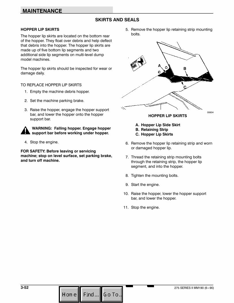
MAINTENANCE
3-52 275 SERIES II MM190 (6---90)
SKIRTS AND SEALS
HOPPER LIP SKIRTS
The hopper lip skirts are located on the bottom rearof the hopper. They float over debris and help deflectthat debris into the hopper. The hopper lip skirts aremade up of five bottom lip segments and twoadditional side lip segments on multi-level dumpmodel machines.
The hopper lip skirts should be inspected for wear ordamage daily.
TO REPLACE HOPPER LIP SKIRTS
1. Empty the machine debris hopper.
2. Set the machine parking brake.
3. Raise the hopper, engage the hopper supportbar, and lower the hopper onto the hoppersupport bar.
WARNING: Falling hopper. Engage hoppersupport bar before working under hopper.
4. Stop the engine.
FOR SAFETY: Before leaving or servicingmachine; stop on level surface, set parking brake,and turn off machine.
5. Remove the hopper lip retaining strip mountingbolts.
AB
C
00604
HOPPER LIP SKIRTS
A. Hopper Lip Side SkirtB. Retaining StripC. Hopper Lip Skirts
6. Remove the hopper lip retaining strip and wornor damaged hopper lip.
7. Thread the retaining strip mounting boltsthrough the retaining strip, the hopper lipsegment, and into the hopper.
8. Tighten the mounting bolts.
9. Start the engine.
10. Raise the hopper, lower the hopper supportbar, and lower the hopper.
11. Stop the engine.

MAINTENANCE
3-53275 SERIES II MM190 (6---90)
BRUSH DOOR SKIRTS
The brush door skirts are located on the bottom ofeach of the two main brush doors. They seal themain brush compartment. They should clear the floorup to a maximum of 0.25 in (5 mm).
The skirts should be inspected for wear or damageand adjustment daily.
TO REPLACE AND ADJUST BRUSH DOOR SKIRTS
1. Park the machine on a smooth, level surface.
2. Stop the engine and set the machine parkingbrake.
FOR SAFETY: Before leaving or servicingmachine; stop on level surface, set parking brake,and turn off machine.
3. Open the main brush doors.
4. Remove the brush door skirt retaining bolts.
A
B
C
00570
BRUSH DOOR SKIRT
A. Brush Door SkirtB. Skirt Retaining StripC. Brush Door
5. Remove the skirt retaining strip and the doorskirt.
6. Position the new door skirt and skirt retainingstrip on the brush door.
7. Thread the skirt retaining bolts through thebrush door, the door skirt, and into the skirtretaining strip.
NOTE: The brush door skirts have slotted holes toallow for a ground clearance adjustment. The doormust be closed for proper adjustment.
8. Slide the brush door skirt up or down so thatthe skirt clears the floor by 0.25 in (5 mm).
9. Tighten the skirt retaining bolts.
10. Close the brush doors.

MAINTENANCE
3-54 275 SERIES II MM190 (6---90)
REAR SKIRTS
The rear skirts are located on the bottom rear of themain brush compartment. They seal the main brushcompartment. They should clear the floor up to amaximum of 0.25 in (5 mm).
The seals should be inspected for wear or damageand adjustment daily.
TO REPLACE AND ADJUST THE REAR SKIRTS
1. Park the machine on a smooth, level surface.
2. Stop the engine and set the machine parkingbrake.
FOR SAFETY: Before leaving or servicingmachine; stop on level surface, set parking brake,and turn off machine.
3. Open the main brush doors.
4. Remove the main brush as described in TOREPLACE MAIN BRUSH.
A
B
C
C
D
00606
REAR SKIRTS
A. Brush Idler Arm HubB. Skirt Mounting BracketC. Rear Floor SkirtD. Brush Contact Skirt
5. Remove the skirt mounting bracket and thebrush contact skirt.
6. Remove the rear floor skirt from the skirtmounting bracket.
7. Thread the rear floor skirt retaining stripmounting bolts through the retaining strip, thenew rear floor skirt, and into the skirt mountingbracket.
8. Do not tighten the mounting bolts at this time.
9. Thread the retaining bolts through the skirtmounting bracket, the brush contact skirt, andinto the machine frame.
10. Tighten the retaining bolts.
11. Slide the rear floor skirt up or down so that theskirt clears the floor up to a maximum of 0.25 in(5 mm).
12. Tighten the rear floor skirt mounting bolts.
13. Reinstall the main brush.

MAINTENANCE
3-55275 SERIES II MM190 (6---90)
MAIN BRUSH DOOR SEALS
The main brush door seals are located on both mainbrush doors and on corresponding portions of themain frame. They seal the main brush compartment.
The seals should be inspected for wear or damageafter every 100 hours of operation.
A
B
00570
BRUSH ACCESS DOOR SEALS
A. Brush Access DoorB. Door Seals
HOPPER SEALS
The hopper seals are located on the top and sideportions of the machine frame which contact thehopper. They seal the main brush compartment.
The seals should be inspected for wear or damageafter every 100 hours of operation.
A B
C
02457
HOPPER SEALS
A. Side SealB. Seal Retaining StripC. Top Seal
HOPPER INSPECTION DOOR SEAL
The hopper inspection door seal is located on thehopper inspection door on low dump modelmachines. It seals the front of the debriscompartment.
The seal should be checked for wear or damageafter every 100 hours of operation.
AB
02480
HOPPER INSPECTION DOOR SEAL
A. Hopper Inspection DoorB. Door Seal

MAINTENANCE
3-56 275 SERIES II MM190 (6---90)
HOPPER DOOR SEALS
The hopper door seals are located around thehopper door opening on multi-level dump modelmachines. They seal the hopper door.
The seals should be checked for wear or damageafter every 100 hours of operation.
A
B
C02481
HOPPER DOOR SEALS
A. SealB. HopperC. Hopper Door
HOPPER COVER SEAL
The hopper cover seal is located on the top edges ofthe hopper. It seals the hopper filter compartment.
The seal should be checked for wear or damageafter every 100 hours of operation.
A B
02482
HOPPER COVER SEAL
A. Hopper CoverB. Cover Seal
HOPPER VACUUM FAN SEAL
The hopper vacuum fan seal is mounted to the lintelon multi-level dump model machines. It seals thehopper filter compartment to the vacuum fan intakebracket.
The seal should be checked for wear or damageafter every 100 hours of operation. Check to makesure that the seal is making good contact with thehopper. The seal should be compressed 0.12 in(3 mm) by the contact.
AB C
D
02465
HOPPER VACUUM FAN SEAL
A. LintelB. SealC. Mounting BoltsD. Bracket
To adjust seal contact, loosen the vacuum fan intakebracket mounting bolts. Pivot the bracket into thecorrect position and retighten the bolts.

MAINTENANCE
3-57275 SERIES II MM190 (6---90)
BRAKES AND TIRES
SERVICE BRAKES
The mechanical service brakes are located on thefront wheels. They are operated by the foot brakepedal and connecting linkages.
The brake pedal should not travel more than 1 in (25mm) to fully engage the brakes. Blow theaccumulated dirt from between the brake shoes andthe hub with compressed air through the slots on theside wheel pockets. Check the brake adjustmentafter every 200 hours of operation.
TO ADJUST BRAKE LINKAGE
1. Empty the debris hopper.
2. Park machine on a level surface.
3. Raise the hopper, engage the hopper supportbar, and lower the hopper onto the support bar.
WARNING: Falling hopper. Engage hoppersupport bar before working under hopper.
4. Stop the engine.
FOR SAFETY: Before leaving or servicingmachine; stop on level surface, set parking brake,and turn off machine.
5. Block machine tires.
6. Remove the clevis pins from the left and rightside brake clevises.
AB C
02457
BRAKE CLEVIS
A. Brake Adjusting ClevisB. Threaded RodC. Brake Cross Shaft
7. Thread the clevis out to decrease brake pedalheight, or in to increase brake pedal height.Both clevises must be turned the sameamount.
8. Adjust the brake linkage so that the brakepedal travels no more than 1 in (25 mm) to fullyengage the brakes. If the brake pedal travelsmore than 1 in (25 mm), it indicates the brakeclevises are not adjusted the same. Readjustas necessary.
9. Reinstall the brake clevis pins.
10. Start the engine and raise the hopper.
11. Lower the hopper bar.
12. Lower the hopper and stop the engine.
13. Remove the machine tire blocks.
PARKING BRAKES
The parking brakes are engaged by the parkingbrake lever which activates the service brake linkage.
The parking brakes should be adjusted whenever itbecomes very easy to engage the parking brake,when the machine rolls after engaging the parkingbrake, and after every 200 hours of operation. Theparking brake may be routinely tightened by turningthe knurled knob on the end of the parking brakeclockwise. If the knob adjustment is inadequate, fullyloosen the knob and adjust the brake linkage asdescribed in To Adjust Brake Linkage. Adjust theparking brake so it will hold the machine on asmooth 8_ ramp.
TIRES
The standard front machine tires are solid.
The standard rear machine tire is pneumatic.
Check the tire pressure after every 100 hours ofoperation. The proper tire air pressure is 80 + 5 psi(550 + 35 kPa). When the machine is equipped witha scrub attachment, the proper air pressure is 70 +5 psi (480 + 35 kPa).
A solid rear tire is available as an accessory.

MAINTENANCE
3-58 275 SERIES II MM190 (6---90)
SCRUB ATTACHMENT
SCRUB ATTACHMENT
The scrub attachment accessory gives the machinethe added flexibility to scrub floors. It consists ofthree groups of parts --- the scrub attachment, theside scrub brush and squeegee, and the rearsqueegee. The scrub attachment includes twosolution tanks, a solution distribution system, threescrub brushes, a recovery tank, and a debris hopper.
SOLUTION TANKS
The two solution tanks supply the scrub brush with awater and detergent solution. They are located in thetop right and left sides of the scrub attachment.
Access to the tanks is through the solution tankcovers on the top of the scrub attachment.
The solution tanks require no regular maintenance. Ifdetergent cakes on the bottom of the tank, removethe deposits with a strong blast of water.
SOLUTION DISTRIBUTION SYSTEM
The solution is distributed by feed lines from thesolution tanks to an on-off solenoid valve, to a cablecontrolled flow-rate valve, then to a solution spreadertube.
The solution spreader tube distributes scrub solutionto the scrub brushes. It may be flushed out if itbecomes clogged. A drain plug is located on eachend of the spreader tube.
Before cleaning the solution spreader tube, makesure that the cable controlled flow-rate valve isopening fully when the solution flow knob is pulledout.
A brush and hot water may be needed to removestubborn clogs. A sharp instrument may be used toclear the small distribution holes in the spreadertube.
A
B
C
02769
SPREADER TUBE
A. Recovery TankB. Spreader TubeC. Distribution Holes
SCRUB BRUSHES
Three scrub brushes are utilized by the scrubattachment --- the side brush, the main brush, and ascrub brush located in the scrub attachment. Theside brush scrubs and deflects debris into the pathof the scrub brush. The scrub brush scrubs anddeflects debris backward, the main brush scrubsand deflects debris into the debris hopper.
The brushes should be inspected daily for damageor wear. Remove any string or wire found tangled onthe scrub brushes, drive, or idler hubs.
Replace the scrub brushes when the brush bristle is0.5 in (15 mm) or less in length. To replace the sidebrush, see TO REPLACE SIDE BRUSH. To replacethe scrub brush, see TO REPLACE SCRUB BRUSH.To replace the main brush, see TO REPLACE MAINBRUSH.
The scrub brush patterns should be checked daily.They should be 2 to 3 in (50 to 75 mm) wide. Thescrub brush pattern is adjusted by changing theposition of the clevis on the threaded stud of the liftlinkage. See TO CHECK AND ADJUST SCRUBBRUSH PATTERN.

MAINTENANCE
3-59275 SERIES II MM190 (6---90)
TO REPLACE SCRUB BRUSH
1. Start the engine, raise the scrub attachment,and engage the hopper support bar.
WARNING: Falling hopper. Engage hoppersupport bar before working under hopper.
2. Stop the engine and set the machine parkingbrake.
FOR SAFETY: Before leaving or servicingmachine; stop on level surface, set parking brake,and turn off machine.
3. Remove the brush idler arm nut.
AB
C
02778
IDLER ARM
A. Idler ArmB. NutC. Scrub Brush
4. Pull the brush idler arm off the arm bracket.
5. Pull the scrub brush off the drive hub.
A
BC
02770
REMOVING SCRUB BRUSH
A. BracketB. Idler ArmC. Scrub Brush
6. Align the scrub brush drive slots with the drivekeys on the drive nuts.
7. Slide the scrub brush onto the drive hub.
8. Slide the idler hub onto the scrub brush andarm bracket.
9. Secure the idler arm with nut.
10. Check and adjust scrub brush pattern asdescribed in TO CHECK AND ADJUST SCRUBBRUSH PATTERN.
TO CHECK AND ADJUST SCRUB BRUSH PATTERN
1. Apply chalk, or some other material that will notblow away easily, on a smooth, level floor.
2. With the scrub brush position lever in the (SideBrush Up) position, move the scrub attachmentover the test area. Set the parking brake.
3. Place the main brush, vacuum fan and filtershaker switch in the bottom (Main Brush On)position.

MAINTENANCE
3-60 275 SERIES II MM190 (6---90)
4. Place the scrub brush position lever in the“normal” position for 15 to 20 seconds, thenreturn the lever to the “raised” position.
NOTE: If no chalk or other material is available, allowthe brushes to spin approximately two minutes. It willmake a polish mark on the floor.
5. Place the main brush, vacuum fan and filtershaker switch in the middle position.
6. Release the parking brake and remove themachine from the test area.
7. The scrub brush pattern should be 2 in(50 mm) across the full length of the brush.
AB
00582
NORMAL SCRUB BRUSH PATTERN
A. Scrub Brush PatternB. 2 in (50 mm)
To adjust the width of the pattern, adjust the positionof the lift linkage clevis on the threaded stud. Threadthe stud into the clevis to decrease the width. Threadthe stud out of the clevis to increase the width.
A
B
02747
LIFT LINKAGE
A. ClevisB. Stud
If the brush pattern is tapered more than 0.25 in (5mm), the scrub brush must be checked to see if it iscone shaped.
00601
TAPERED SCRUB BRUSH PATTERN
If the brush is not cone shaped, the scrub brushdrive mechanism must be leveled by adding orremoving shims between the scrub brush cross shaftbearing blocks and the scrub attachment frame.
A
BC
02771
CROSS SHAFT SHIM
A. ShimB. Bearing BlockC. Cross Shaft
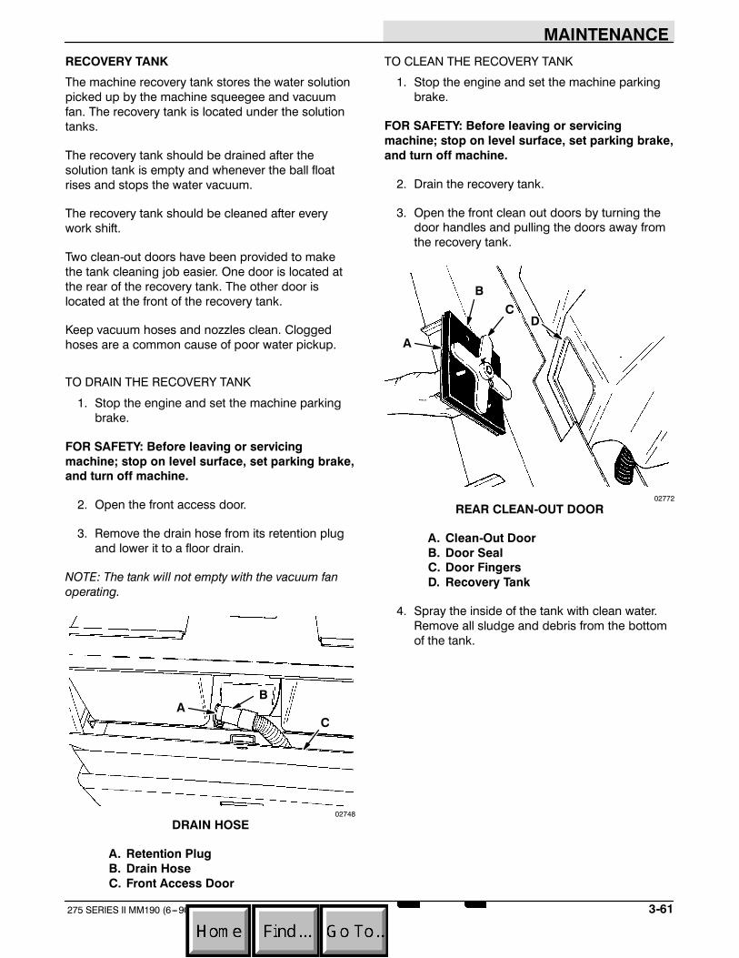
MAINTENANCE
3-61275 SERIES II MM190 (6---90)
RECOVERY TANK
The machine recovery tank stores the water solutionpicked up by the machine squeegee and vacuumfan. The recovery tank is located under the solutiontanks.
The recovery tank should be drained after thesolution tank is empty and whenever the ball floatrises and stops the water vacuum.
The recovery tank should be cleaned after everywork shift.
Two clean-out doors have been provided to makethe tank cleaning job easier. One door is located atthe rear of the recovery tank. The other door islocated at the front of the recovery tank.
Keep vacuum hoses and nozzles clean. Cloggedhoses are a common cause of poor water pickup.
TO DRAIN THE RECOVERY TANK
1. Stop the engine and set the machine parkingbrake.
FOR SAFETY: Before leaving or servicingmachine; stop on level surface, set parking brake,and turn off machine.
2. Open the front access door.
3. Remove the drain hose from its retention plugand lower it to a floor drain.
NOTE: The tank will not empty with the vacuum fanoperating.
AB
C
02748
DRAIN HOSE
A. Retention PlugB. Drain HoseC. Front Access Door
TO CLEAN THE RECOVERY TANK
1. Stop the engine and set the machine parkingbrake.
FOR SAFETY: Before leaving or servicingmachine; stop on level surface, set parking brake,and turn off machine.
2. Drain the recovery tank.
3. Open the front clean out doors by turning thedoor handles and pulling the doors away fromthe recovery tank.
A
BC
D
02772
REAR CLEAN-OUT DOOR
A. Clean-Out DoorB. Door SealC. Door FingersD. Recovery Tank
4. Spray the inside of the tank with clean water.Remove all sludge and debris from the bottomof the tank.
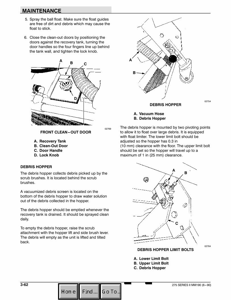
MAINTENANCE
3-62 275 SERIES II MM190 (6---90)
5. Spray the ball float. Make sure the float guidesare free of dirt and debris which may cause thefloat to stick.
6. Close the clean-out doors by positioning thedoors against the recovery tank, turning thedoor handles so the four fingers line up behindthe tank wall, and tighten the lock knob.
A B C
D
02769
FRONT CLEAN--OUT DOOR
A. Recovery TankB. Clean-Out DoorC. Door HandleD. Lock Knob
DEBRIS HOPPER
The debris hopper collects debris picked up by thescrub brushes. It is located behind the scrubbrushes.
A vacuumized debris screen is located on thebottom of the debris hopper to draw water solutionout of the debris collected in the hopper.
The debris hopper should be emptied whenever therecovery tank is drained. It should be sprayed cleandaily.
To empty the debris hopper, raise the scrubattachment with the hopper lift and side brush lever.The debris will empty as the unit is lifted and tiltedback.
A
B
02754
DEBRIS HOPPER
A. Vacuum HoseB. Debris Hopper
The debris hopper is mounted by two pivoting pointsto allow it to float over large debris. It is equippedwith float limiter. The lower limit bolt should beadjusted so the hopper has 0.3 in(10 mm) clearance with the floor. The upper limit boltshould be set so the hopper will travel up to amaximum of 1 in (25 mm) clearance.
AB
C
02764
DEBRIS HOPPER LIMIT BOLTS
A. Lower Limit BoltB. Upper Limit BoltC. Debris Hopper

MAINTENANCE
3-63275 SERIES II MM190 (6---90)
SIDE SQUEEGEE
The side squeegee controls water spray andchannels water into the path of the rear squeegee.Check the side squeegee for damage, wear andadjustment daily. Replace the squeegee bladewhenever it becomes damaged or loses its shape orresiliency.
TO REPLACE SIDE SQUEEGEE BLADE
1. Stop the engine and set the machine parkingbrake.
FOR SAFETY: Before leaving or servicingmachine; stop on level surface, set parking brake,and turn off machine.
2. Disconnect the squeegee assembly chain fromthe chain hook.
A
B
C
D E
02758
SIDE SQUEEGEE ASSEMBLY
A. Squeegee BladeB. Pin KeeperC. Retaining PinD. ChainE. Hook
3. Pull the pin keeper out and remove the twosqueegee assembly retaining pins. Release thepin keeper.
4. Slide the squeegee assembly out of themachine.
5. Remove the five squeegee retaining bolts fromthe squeegee assembly.
6. Remove the squeegee blade from thesqueegee frame.
7. Position a new squeegee blade on thesqueegee frame.
8. Secure the blade with the blade retainer andretaining bolts.
9. Slide the squeegee assembly into position inthe squeegee bracket.
10. Slide the two squeegee retaining pins throughthe bracket and squeegee assembly.
A
B
C
02757
SECURING SQUEEGEE RETAINING PINS
A. Squeegee AssemblyB. Pin KeeperC. Pin
11. Pull the pin keeper out, turn the squeegeeretaining pins so they are under the pin keeper,and release the keeper.
12. Connect the squeegee assembly chain to thechain hook.

MAINTENANCE
3-64 275 SERIES II MM190 (6---90)
REAR SQUEEGEE
The rear squeegee assembly channels water into thevacuum fan suction. The front squeegee bladechannels the water,and the rear blade wipes thefloor. Check the rear squeegee assembly fordamage, wear, and adjustment daily.
Rotate or replace the front or rear blade of the rearsqueegee if its leading edge is worn one-half of theway through the thickness of the blade.
Each front and rear blade has four wiping edges. Touse them all, start with one wiping edge. To use thenext wiping edge, swap the squeegee end-for-end.To use the next wiping edge, rotate the top edgesdown, bottom edges up. To use the last edge, swapthe squeegee end-for-end. Replace the back---upstrips if they become damaged, or if they lose theirresiliency.
TO REPLACE OR ROTATE REAR BLADE
1. Press the squeegee switch into the (SqueegeeDown) position.
2. Stop the engine and set the machine parkingbrake.
FOR SAFETY: Before leaving or servicingmachine; stop on level surface, set parking brake,and turn off machine.
3. Remove the retaining pin from each end of thesqueegee. Remove the end brackets.
A
B
CD
02773
REMOVING RETAINING PINS
A. Retaining PinB. End BracketC. Squeegee BladeD. Band
4. Open the rear band clamp and remove thesqueegee back-up strip and the squeegeeblade.
5. Replace or rotate the rear blade to allow a newedge of the blade to face the front of themachine.
A
B
C
DE
F02774
DISASSEMBLED REAR SQUEEGEE
A. FrameB. End BracketC. Retaining PinD. BladeE. Back--Up StripF. Retaining Band
6. Place the squeegee blade over the pins of thesqueegee frame.
7. Place the squeegee back-up strip on the pins.
8. Position the squeegee retaining bands over theback-up strip.
9. Replace the end brackets. Secure with theretaining pins.
10. Adjust the rear squeegee as described inTO CHECK AND ADJUST REAR SQUEEGEE.

MAINTENANCE
3-65275 SERIES II MM190 (6---90)
TO REPLACE OR ROTATE FRONT BLADE
1. Press the squeegee switch into the “down”position.
2. Stop the engine and set the machine parkingbrake.
FOR SAFETY: Before leaving or servicingmachine; stop on level surface, set parking brake,and turn off machine.
3. Disconnect the rear squeegee suction hosefrom the squeegee frame.
4. Remove the two squeegee frame nuts andlower the squeegee assembly from thesqueegee cross bar.
A B
C
04635
CROSS BAR
A. Cross BarB. Squeegee Frame NutC. Squeegee Assembly
5. Remove the retaining pins from each end of thesqueegee. Remove the end brackets.
A
B
CD
02773
REMOVING RETAINING PINS
A. Retaining PinB. End BracketC. Squeegee BladeD. Band
6. Remove the hair cotter pin from the center ofthe front retaining band.
7. Pull the retaining band, back-up strip, andsqueegee blade off the squeegee frame.
8. Replace or rotate the front blade to allow a newedge of the blade to face the front of themachine.
9. Place the squeegee blade over the pins on thesqueegee frame.

MAINTENANCE
3-66 275 SERIES II MM190 (6---90)
10. Place the back-up strip on the pins.
11. Position the ends of the retaining band in theslots at the ends of the squeegee frame.
12. Press the center of the retaining band intoplace.
A BC
02775
INSTALLING RETAINING BAND
A. Retaining BandB. SqueegeeC. Hair Cotter Pin
13. Secure the retaining band with the hair cotterpin removed earlier.
14. Replace the end brackets. Secure with theretaining pins.
15. Lift the squeegee frame into position on thecross bar. Secure with the nuts removed earlier.
16. Reconnect the squeegee suction hose to thesqueegee frame.
TO CHECK AND ADJUST REAR SQUEEGEE
1. Start the engine.
2. Lower the squeegee and move the machineforward.
3. Stop the engine and set the machine parkingbrake.
FOR SAFETY: Before leaving or servicingmachine; stop on level surface, set parking brake,and turn off machine.
4. Check the squeegee. It should contact the floorevenly side-to-side and deflect 0.88 in (20 mm)for smooth floors and 1.5 in(40 mm) for rough floors. If not, continue withstep 5.
A
B
03719
SQUEEGEE DEFLECTION
A. SqueegeeB. Deflection
NOTE: The squeegee blades must be new or have anew wiping edge contacting the floor to correctlyadjust the squeegee.
5. Check the squeegee lift cable. It should beloose when the squeegee actuator is in theextended “lower” position. The squeegeeshould clear the floor when the lever is in theretracted “lift” position.
6. Start the engine, release the parking brake,raise and lower the squeegee. Then move themachine forward to deflect the squeegeeblades.
7. Stop the engine and set the machine parkingbrake.
FOR SAFETY: Before leaving or servicingmachine; stop on level surface, set parking brake,and turn off machine.

MAINTENANCE
3-67275 SERIES II MM190 (6---90)
8. Level the squeegee from front to rear with thetwo squeegee adjustment bolts on the crossbar.
To lower the squeegee tips, thread theadjustment bolts counter-clockwise evenly oneach side.
To raise the squeegee tips, thread theadjustment bolts clockwise evenly on eachside.
A
B C
04635
TIPS ADJUSTMENT BOLT
A. Squeegee AssemblyB. Adjustment BoltC. Cross Bar
9. Adjust the squeegee deflection with the twosqueegee adjustment studs.
To increase deflection, increase down pressureby adjusting the stud forward.
A B C
04634
SQUEEGEE STUD
A. SqueegeeB. StudC. Jam Nut
To decrease deflection, decrease downpressure by adjusting the stud backward.
Loosen the jam nuts on both ends of the rodsbefore making adjustments. Tighten the jamnuts after making any adjustments.
10. Adjust the squeegee guards on each side ofthe machine so they clear the floor by 1.5 in (40mm).
A B
04629
SQUEEGEE GUARD
A. GuardB. Squeegee

MAINTENANCE
3-68 275 SERIES II MM190 (6---90)
SNOW BROOM
SNOW BROOM
The snow broom accessory gives the machine theadded flexibility to remove snow from walks anddriveways. It consists of two groups of parts: Themounting frame, and the broom frame and driveassembly. The mounting frame is used to mounteither the snow blade or snow broom assembly tothe machine. The broom frame and drive assemblymay be positioned so as to sweep snow to the left orright of the machine. Check the snow broom fortangled string or wire after each use. Replace thesnow broom when the remaining bristles measure1.25 in (30 mm) or less in length.
TO REPLACE SNOW BROOM
1. Stop the engine and set the machine parkingbrake.
FOR SAFETY: Before leaving or servicingmachine; stop on level surface, set parking brake,and turn off machine.
2. Remove the bolt holding the idler arm to thecross shaft.
A
B C
02763
IDLER ARM
A. Cross ShaftB. BoltC. Idler Arm
3. Pull the idler plug out of the snow broom.
4. Pull the snow broom off the drive plug.
5. Slide the new snow broom onto the drive plug,making sure the drive keys and slots line up.
6. Slide the idler plug into the snow broom.
7. Secure the idler arm to cross shaft with thebolt.

APPENDIX
4-1275 SERIES II MM190 (12---89)
SECTION 4CONTENTS
PageHARDWARE INFORMATION 4-3. . . . . . . . . . . . . . . .
STANDARD BOLT TORQUE CHART 4-3. . . . . .METRIC BOLT TORQUE CHART 4-3. . . . . . . . .BOLT IDENTIFICATION 4-3. . . . . . . . . . . . . . . . .THREAD SEALANT AND LOCKING
COMPOUNDS 4-3. . . . . . . . . . . . . . . . . . . . . .HYDRAULIC FITTING INFORMATION 4-4. . . . . . . .
HYDRAULIC TAPERED PIPE FITTING (NPT)TORQUE CHART 4-4. . . . . . . . . . . . . . . . . . . .
HYDRAULIC TAPERED SEAT FITTING (JIC)TORQUE CHART 4-4. . . . . . . . . . . . . . . . . . . .
HYDRAULIC O---RING FITTINGTORQUE CHART 4-4. . . . . . . . . . . . . . . . . . . .

APPENDIX
275 SERIES II MM190 (12---89)4-2
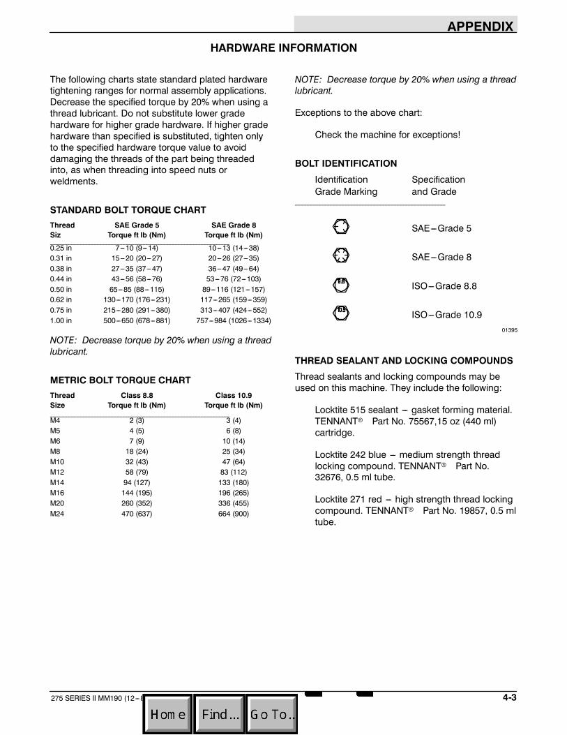
APPENDIX
4-3275 SERIES II MM190 (12---89)
HARDWARE INFORMATION
The following charts state standard plated hardwaretightening ranges for normal assembly applications.Decrease the specified torque by 20% when using athread lubricant. Do not substitute lower gradehardware for higher grade hardware. If higher gradehardware than specified is substituted, tighten onlyto the specified hardware torque value to avoiddamaging the threads of the part being threadedinto, as when threading into speed nuts orweldments.
STANDARD BOLT TORQUE CHARTThread SAE Grade 5 SAE Grade 8Siz Torque ft lb (Nm) Torque ft lb (Nm)______________________________________________________________0.25 in 7---10 (9---14) 10---13 (14---38)0.31 in 15---20 (20---27) 20---26 (27---35)0.38 in 27---35 (37---47) 36---47 (49---64)0.44 in 43---56 (58---76) 53---76 (72---103)0.50 in 65---85 (88---115) 89---116 (121---157)0.62 in 130---170 (176---231) 117---265 (159---359)0.75 in 215---280 (291---380) 313---407 (424---552)1.00 in 500---650 (678---881) 757---984 (1026---1334)
NOTE: Decrease torque by 20% when using a threadlubricant.
METRIC BOLT TORQUE CHARTThread Class 8.8 Class 10.9Size Torque ft lb (Nm) Torque ft lb (Nm)______________________________________________________________M4 2 (3) 3 (4)M5 4 (5) 6 (8)M6 7 (9) 10 (14)M8 18 (24) 25 (34)M10 32 (43) 47 (64)M12 58 (79) 83 (112)M14 94 (127) 133 (180)M16 144 (195) 196 (265)M20 260 (352) 336 (455)M24 470 (637) 664 (900)
NOTE: Decrease torque by 20% when using a threadlubricant.
Exceptions to the above chart:
Check the machine for exceptions!
BOLT IDENTIFICATION
Identification SpecificationGrade Marking and Grade
____________________________________________________
SAE---Grade 5
SAE---Grade 8
ISO---Grade 8.8
ISO---Grade 10.901395
THREAD SEALANT AND LOCKING COMPOUNDS
Thread sealants and locking compounds may beused on this machine. They include the following:
Locktite 515 sealant --- gasket forming material.TENNANTr Part No. 75567,15 oz (440 ml)cartridge.
Locktite 242 blue --- medium strength threadlocking compound. TENNANTr Part No.32676, 0.5 ml tube.
Locktite 271 red --- high strength thread lockingcompound. TENNANTr Part No. 19857, 0.5 mltube.

APPENDIX
275 SERIES II MM190 (12---89)4-4
HYDRAULIC FITTING INFORMATION
HYDRAULIC TAPERED PIPE FITTING (NPT)TORQUE CHART
NOTE: Ratings listed are when using teflon threadseal.
Minimum MaximumSize Torque Torque______________________________________________________________1/4 NPT 10 ft lb (14 Nm) 30 ft lb (41 Nm)1/2 NPT 25 ft lb (34 Nm) 50 ft lb (68 Nm)3/4 NPT 50 ft lb (68 Nm) 100 ft lb (136 Nm)
HYDRAULIC TAPERED SEAT FITTING (JIC)TORQUE CHARTTube Thread MaximumO.D. (in) Size Torque______________________________________________________________0.25 0.44---20 9 ft lb (12 Nm)0.38 0.56---18 20 ft lb (27 Nm)0.50 0.75---16 30 ft lb (41 Nm)0.62 0.88---14 40 ft lb (54 Nm)0.75 1.12---12 70 ft lb (95 Nm)1.0 1.31---12 90 ft lb (122 Nm)
HYDRAULIC O--RING FITTING TORQUE CHARTTube Thread Minimum MaximumO.D.(in) Size Torque Torque______________________________________________________________0.25 0.44---20 6 ft lb (8 Nm) 9 ft lb (12 Nm)0.38 0.56---18 13 ft lb (18 Nm) 20 ft lb (27 Nm)
*10 ft lb (14 Nm) 12 ft lb (16 Nm)0.50 0.75---16 20 ft lb (27 Nm) 30 ft lb (41 Nm)
*21 ft lb (28 Nm) 24 ft lb (33 Nm)0.62 0.88---14 25 ft lb (34 Nm) 40 ft lb (54 Nm)0.75 1.12---12 45 ft lb (61 Nm) 70 ft lb (95 Nm)1.0 1.31---12 60 ft lb (81 Nm) 90 ft lb (122 Nm)
NOTE: Do not use sealant on o---ring threads.
*Aluminum bodied components