26 792 en manual system cables and adapters
DESCRIPTION
saya, sistem cableTRANSCRIPT

Manual:
Document-No. 26/792; Edition EN 04; 2012-02-17
System cables and adapters for PCD1/PCD2/PCD3 Series
Controls Division

Manual System cables and adapters for the PCD Series│Document 26 / 792│Edition EN 04│2012-02-17
Saia-Burgess Controls AG
Contents
0-1
00 Index
0.1 Document history ............................................................................................ 0-20.2 Trademarks ..................................................................................................... 0-2
1 Modular concept of the I/O level1.1 The modular concept offers optimum adaptability .......................................... 1-1
2 System cables 2.1 System cables with I/O module connections to the PCD ................................ 2-1
2.1.1 PCD2.K221 and PCD2.K223 cables ............................................................... 2-22.1.2 PCD2.K231 and PCD2.K232 cables ............................................................... 2-32.1.3 PCD2.K241 and PCD2.K242 cables ............................................................... 2-42.1.4 PCD2.K261 and PCD2.K263 cables ............................................................... 2-52.1.5 PCD2.K271 and PCD2.K273 cables ............................................................... 2-62.1.6 PCD2.K281 and PCD2.K283 cables ............................................................... 2-72.1.7 PCD3.K800 cables .......................................................................................... 2-82.1.8 PCD3.K810 cables ......................................................................................... 2-92.1.9 PCD3.K860 cables .......................................................................................... 2-102.1.10 PCD3.K861 cables ......................................................................................... 2-11
3 System adapters3.1 Ribbon/screw terminal adapters (external terminal blocks) ............................ 3-1
3.1.1 PCD2.K510 and PCD2.K511 adapters ........................................................... 3-23.1.2 PCD2.K520 and PCD2.K521 adapters ........................................................... 3-33.1.3 PCD2.K525 adapter ....................................................................................... 3-43.1.4 PCD2.K551 relay interface with relay type G2RL-1 ........................................ 3-53.1.5 PCD2.K552 relay interface with manual control ............................................ 3-6
A AppendixA.1 Icons ............................................................................................................... A-1A.2 Dimensioned drawings .................................................................................... A-2
A.2.1 PCD2.K510 and PCD2.K511 .......................................................................... A-2A.2.2 PCD2.K520 and PCD2.K521 .......................................................................... A-2A.2.3 PCD2.K525 ..................................................................................................... A-2A.2.4 PCD2.K551 ..................................................................................................... A-3A.2.5 PCD2.K552 ..................................................................................................... A-3
A.4 Order codes .................................................................................................... A-4A.5 Address of Saia-Burgess Controls AG ............................................................ A-5
0 Index

Manual System cables and adapters for the PCD Series│Document 26 / 792│Edition EN 04│2012-02-17
Saia-Burgess Controls AG
Contents
0-2
00.1 Document history
Published Version Changed Remarks21.07.2000 E1 old 1.2.4 Relay interface with relay type G2RL-128.02.2004 E2 old 1.2.4 Jumper on adapter PCD2.K5252008-12-23 EN3 complete added the cables PCD3.K8xx and the adaptor
PCD2.K5522009-03-03 EN3 Ch 3 K520 and K525, pin 29/31 on L/+2011-06-202012-02-17
EN04 Ch 3 Ribbon connector K525: 34-pole, not 16-polePCD2.K525: No Sink Operation for inputs
0.2 Trademarks
Saia® and Saia® PCD are registered trademarks of Saia-Burgess Controls AG.
STEP7® ,SIMATIC®, S7-300®, S7-400®, and Siemens® are registered trademarks of Siemens AG.
Technical changes are subject to the state of technology.
Saia-Burgess Controls AG, 2000. © All rights reserved.
Published in Switzerland

Manual System cables and adapters for the PCD Series│Document 26 / 792│Edition EN 04│2012-02-17
Saia-Burgess Controls AG
Content
1-1
1
1 Modular concept of the I/O level
On the I/O bus, a large number of modules can be plugged into the sockets as
required.
Digital I/O modules Analogue I/O modules Multifunctional I/O modules Counting, measuring and motion control modules Axis control modules
Modem modules
Retaining catch
Insertion of the I/O modules is simply and elegant: push the module into the side opening until it reaches the end stop, then lock the retaining catch in place – the module is fixed rigidly in position.
Bus connectorCPU and I/O bus
Standard connection via plug-in screw terminals
Plug-in spring terminals as option for PCD2.M170/..M177
1.1 The modular concept offers optimum adaptability
Economic: The modular structure means that it is only necessary to include (and pay for) those functions that are actually required for a specific application.
Flexible: All modules of the I/O level can be plugged onto any preferred point on the bus and are easy to exchange. Insertion of the I/O modules is simple and elegant: Push the module into the side opening until it reaches the end stop and lock the retaining catch in place.
Time saved in electrical wiring: Due to plug-in screw terminals, spring terminals or ready-made cable variants and ribbon terminal adapters.
Functional security: Guaranteed by their robust design and excellent reliability (average field failure rate FFR >106 hours).
Manual System cables and adapters for the PCD Series│Document 26 / 792│Edition EN 04│2012-02-17
Saia-Burgess Controls AG
System cables with I/O module connections to the PCD
System cables
2-1
2
2 System cables
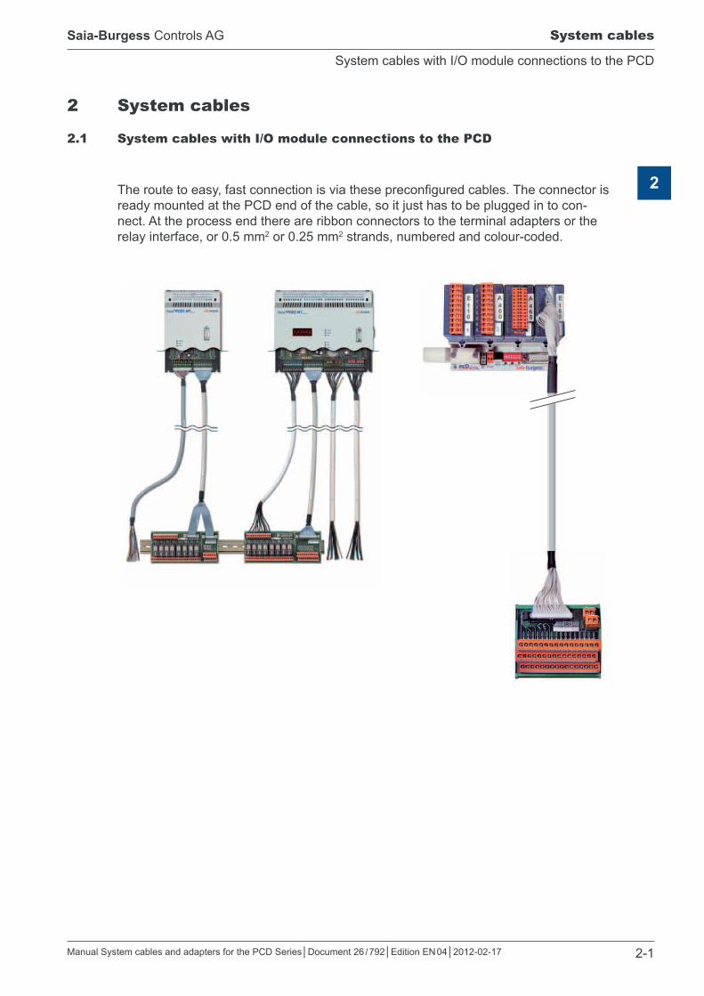
2.1 System cables with I/O module connections to the PCD
The route to easy, fast connection is via these preconfigured cables. The connector is ready mounted at the PCD end of the cable, so it just has to be plugged in to con-nect. At the process end there are ribbon connectors to the terminal adapters or the relay interface, or 0.5 mm2 or 0.25 mm2 strands, numbered and colour-coded.

Manual System cables and adapters for the PCD Series│Document 26 / 792│Edition EN 04│2012-02-17
Saia-Burgess Controls AG
PCD2.K221 and PCD2.K223 cables
System cables
2-2
2
2.1.1 PCD2.K221 and PCD2.K223 cables
This cable is designed for the digital I/O modules PCD2/3.E160/161 and PCD2/3.A460 with 16 inputs / outputs, with a 34-pole ribbon connector.
2 1
34 33
PCD2.K221
100 mm 50 mm
Con
nect
or v
iew
fro
m b
elow
Rubber grommet
Label Diameter = 11 mm
Length = 1.5 m respectively 3.0 m
Sheathed, round cable with 32 strands of 0.25 mm2 (AWG 24)PCD end: 34-pole ribbon connector, Free end: 10 cm unsheathed, colour-coded strands
Colour coding and pin configuration:
Pin Colour Pin Colour Pin Colour Pin Colour1 white 9 black 17 white/grey 25 white/black2 brown 10 purple 18 grey/brown 26 brown/black3 green 11 grey/pink 19 white/pink 27 grey/green4 yellow 12 red/blue 20 pink/brown 28 yellow/grey5 grey 13 white/green 21 white/blue 29 pink/green6 pink 14 brown/green 22 brown/blue 30 yellow/pink7 blue 15 white/yellow 23 white/red 31 green/blue8 red 16 yellow/brown 24 brown/red 32 yellow/blue
The cables are supplied in two lengths: Type and item-number: PCD2.K221 Length 1.5 m Type and item-number: PCD2.K223 Length 3.0 m

Manual System cables and adapters for the PCD Series│Document 26 / 792│Edition EN 04│2012-02-17
Saia-Burgess Controls AG
PCD2.K231 and PCD2.K232 cables
System cables
2-3
2
2.1.2 PCD2.K231 and PCD2.K232 cables
This cable is designed for the digital I/O modules PCD2/3.E160/161 and PCD2/3.A460 with 16 inputs / outputs, with a 34-pole ribbon connector.
2 1
34 33
PCD2.K231
2 1
34 33
50 mm 50 mm
Rubber grommet
Label
Rubber grommet
Diameter = 11 mm
Length = 1.0 m respectively 2.0 m
Con
nect
or v
iew
fro
m b
elow
Unsheathed round cable with 34 strands of 0.09 mm2.34-pole ribbon connector at both ends.
The cables are supplied in two lengths: Type and item-number: PCD2.K231 Length 1.0 m Type and item-number: PCD2.K232 Length 2.0 m

Manual System cables and adapters for the PCD Series│Document 26 / 792│Edition EN 04│2012-02-17
Saia-Burgess Controls AG
PCD2.K241 and PCD2.K242 cables
System cables
2-4
2
2.1.3 PCD2.K241 and PCD2.K242 cables
This cable is designed for the digital I/O modules PCD2/3.E160/161 and PCD2/3.A460 with 16 inputs / outputs, with a 34-pole ribbon connector.
2 1
34 33
PCD2.K241
50 mm
1 2
15 16
2 1
16 15
300 mm
PCD2. K241/2
PCD2. K241/1
Rubber grommet
Label
Rubber grommet
Diameter = 11 mm
Length = 1.0 m respectively 2.0 m
Con
nect
or v
iew
fro
m b
elow
Sheathed round cable with 34 strands of 0.09 mm2.PCD end: 34-pole ribbon connector, Process end: Divided into 2 branches, each 300 mm in length, leading to 16-pole ribbon connectors.
The cables are supplied in two lengths: Type and item-number: PCD2.K241 Length 1.0 m Type and item-number: PCD2.K242 Length 2.0 m

Manual System cables and adapters for the PCD Series│Document 26 / 792│Edition EN 04│2012-02-17
Saia-Burgess Controls AG
PCD2.K261 and PCD2.K263 cables
System cables
2-5
2
2.1.4 PCD2.K261 and PCD2.K263 cables
This cable is designed for digital I/O modules with 10-pole pluggable screw terminal block, i.e. for the modules PCD2/3.E1xx, E500, E6xx, A200, A220, A300, A4xx and B100. (The existing terminal block should be removed).
PCD2.K261
50 mm 100 mm
9
8 7
6
5
4 3
2
1 0
Diameter = 10 mm
Rubber grommet
Lentgh = 1.5 m respectively 3.0 m
Label
Screw terminal Cable0 101 12 23 34 45 56 67 78 89 9
11 9
8
7 6
5
4
3 2
1
0
1 2 3 4 5 6 7 8 9
10
11...
Screw terminal Cable
Sheathed, round cable with 10 strands of 0.5 mm2.PCD end: 10-pole pluggable screw terminal block, Free end: 10 cm with numbered strands
The cables are supplied in two lengths: Type and item-number: PCD2.K261 Length 1.5 m Type and item-number: PCD2.K263 Length 3.0 m

Manual System cables and adapters for the PCD Series│Document 26 / 792│Edition EN 04│2012-02-17
Saia-Burgess Controls AG
PCD2.K271 and PCD2.K273 cables
System cables
2-6
2
2.1.5 PCD2.K271 and PCD2.K273 cables
This shielded cable is designed for analogue I/O modules and for H modules with 10-pole pluggable screw terminal block. (The existing terminal block should be removed).
PCD2.K271
50 mm 100 mm
9
8
7
6
5
4
3
2
Diameter = 8 mm
Rubber bushing
Length = 1.5 m or 3.0 m
ShieldingShielding (free wire 300 mm long)
Label
Screw terminal Cable0 purple1 white2 brown3 green4 yellow5 grey6 pink7 blue8 red9 black
Screw terminal
9
8
7 6
5
4
3 2
1
0
ShieldingCablepurplewhitebrowngreenyellowgreypinkbluered
black
Sheathed, shielded cable with 10 strands of 0.25 mm2. The shielding is drawn out at both ends. PCD end: 10-pole pluggable screw terminal block, Free end: 10 cm strands, colour-coded
The cables are supplied in two lengths: Type and item-number: PCD2.K271 Length 1.5 m Type and item-number: PCD2.K273 Length 3.0 m

Manual System cables and adapters for the PCD Series│Document 26 / 792│Edition EN 04│2012-02-17
Saia-Burgess Controls AG
PCD2.K281 and PCD2.K283 cables
System cables
2-7
2
2.1.6 PCD2.K281 and PCD2.K283 cables
This cable is designed for the PCD2.A250 relay output module as well as the ana-logue modules PCD2/3.W305, PCD2/3.W605 and PCD2/3.W525 with 14-pole plug-in screw terminal block. (The existing terminal block should be removed).
PCD2.K281
50 mm 100 mm
13 1
2 11
10
9
8
7 6
5
4
3
2
1 0
Diameter = 12 mm
Rubber grommet
Length = 1.5 m respectively 3.0 m
Label
Screw terminal Cable0 141 12 23 34 45 56 67 78 89 910 1011 1112 1213 13
15
1234567891011
13 1
2 1
1 10
9
8
7
6
5
4 3
2
1
0
1213
14
15...
Screw terminal Cable
Sheathed, round cable with 14 strands of 0.5 mm2.PCD end: 14-pole pluggable screw terminal block, Free end: 10 cm with numbered strands
The cables are supplied in two lengths: Type and item-number: PCD2.K281 Length 1.5 m Type and item-number: PCD2.K283 Length 3.0 m

Manual System cables and adapters for the PCD Series│Document 26 / 792│Edition EN 04│2012-02-17
Saia-Burgess Controls AG
PCD3.K800 cables
System cables
2-8
2
2.1.7 PCD3.K800 cables
This cable is designed for the manual control modules PCD3.W800 with 4 analogue output channels.
Line ends cut and identified with sliding cable markers. Designation matches terminal number. (Alternative: numbers printed directly onto strand, approx. every 10 cm)
Black cable tie
Strands standard 1 mm2 Colour black
4 405 4934 0 spring terminal, 8 pole. (strand ends bare, 10 mm)
View A(terminal designation)
250
cm
appr
ox. e
very
30
mm
10 c
m
8 strands held together with cable ties, each strand 1.0 mm², 2.5 m long. PCD side: 8 pole, plug-in spring terminal block, type J. Process side: free strands, numbered.
Connection configuration PCD3.K800:
Line
end
s cu
t 876543
A2
A3 21
87654321
PCD3.W800 PCD3.K800
A2
A3

Manual System cables and adapters for the PCD Series│Document 26 / 792│Edition EN 04│2012-02-17
Saia-Burgess Controls AG
PCD3.K810 cables
System cables
2-9
2
2.1.8 PCD3.K810 cables
This cable is designed for the manual control modules PCD3.A810 with 4 relay out-puts
0 6 0 9
.6 .9
6 9
Line ends cut and identified with sliding cable markers. Designation matches terminal number. (Alternative: numbers printed directly onto strand, approx. every 10 cm)
Black cable tie
Strands standard 1 mm2 Colour black
4 405 4936 0 spring terminal, 12 pole (strand ends bare, 10 mm)
View A(terminal designation)
250
cm
App
rox.
eve
ry 3
0 m
m10
cm
Better differentiation of cable designation, numbers 6 and 9
Additional zero
Or point
Or underline
12 strands held together with cable ties, each strand 1.0 mm², 2.5 m long. PCD side: 12 pole, plug-in spring terminal block, type F. Process side: free strands, numbered.
Connection configuration PCD3.K800:
Line
end
s cu
t
87654321
PCD3.A810 PCD3.K810
1211109876543
A0
A1
A2
A3
+–
24 VDC
21
1211109
Manual System cables and adapters for the PCD Series│Document 26 / 792│Edition EN 04│2012-02-17
Saia-Burgess Controls AG
PCD3.K860 cables
System cables
2-10
2
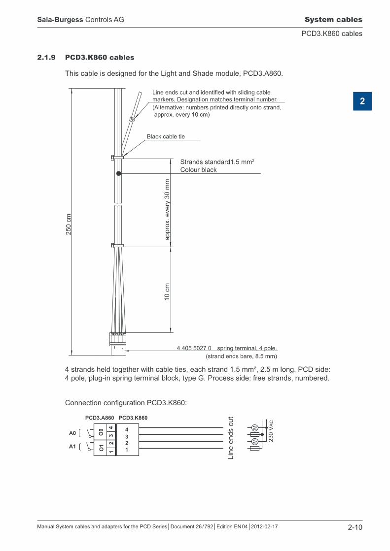
2.1.9 PCD3.K860 cables
This cable is designed for the Light and Shade module, PCD3.A860.
413 24
Line ends cut and identified with sliding cable markers. Designation matches terminal number. (Alternative: numbers printed directly onto strand, approx. every 10 cm)
Black cable tie
Strands standard1.5 mm2 Colour black
4 405 5027 0 spring terminal, 4 pole. (strand ends bare, 8.5 mm)
250
cm
appr
ox. e
very
30
mm
10 c
m
4 strands held together with cable ties, each strand 1.5 mm², 2.5 m long. PCD side: 4 pole, plug-in spring terminal block, type G. Process side: free strands, numbered.
Connection configuration PCD3.K860:
Line
end
s cu
t
MM
4321
PCD3.A860 PCD3.K860
43A0
A1 21
O0
O1
230
VA
C

Manual System cables and adapters for the PCD Series│Document 26 / 792│Edition EN 04│2012-02-17
Saia-Burgess Controls AG
PCD3.K861 cables
System cables
2-11
2
2.1.10 PCD3.K861 cables
This cable is designed for the Light and Shade module, PCD3.A860.
Line ends cut and identified with sliding cable markers. Designation matches terminal number. (Alternative: numbers printed directly onto strand, approx. every 10 cm)
Black cable tie
Strands standard 0.75 mm2 Colour black
4 405 5028 0 spring terminal, 8 pole.(strand ends bare, 7 mm)
View A(terminal designation)
250
cm
appr
ox. e
very
30
mm
10 c
m
6 strands held together with cable ties, each strand 0.75 mm², 2.5 m long. PCD side: 6 pole, plug-in spring terminal block, type H. Process side: free strands, numbered. Connection configuration PCD3.K861:
Line
end
s cu
t
654321
PCD3.A860 PCD3.K861
6543
I0
I1
+– 2
1
–
–
24 VDC
Input 1
Input 0
24 VDC

Manual System cables and adapters for the PCD Series│Document 26 / 792│Edition EN 04│2012-02-17
Saia-Burgess Controls AG
Ribbon/screw terminal adapters
System adapters
3-1
3
3 System adapters
3.1 Ribbon/screw terminal adapters (external terminal blocks)
Terminal blocks for mounting on DIN rails at the output from the switching cabinet, to connect PCD I/O modules to the process. The cables configured for this are described in the previous section “System cables with I/O module connections to the PCD”.

Manual System cables and adapters for the PCD Series│Document 26 / 792│Edition EN 04│2012-02-17
Saia-Burgess Controls AG
PCD2.K510 and PCD2.K511 adapters
System adapters
3-2
3
3.1.1 PCD2.K510 and PCD2.K511 adapters
Ribbon/screw terminal adapters for 8 inputs or 8 outputs.
0 2 4 6 L/+
1 3 5 7 L/+
40 50
82
J1
I/O
J1 I/O
2 7 4 6 6 5 8 4 10 3 12 2 14 1 16 0
1/3 5/7 9/11 13/15 L/+
PCD end: 16-pole ribbon connector Process end: 12 screw terminals 0.5–1.5 mm2
Type and item-number: PCD2.K510 without LEDs Type and item-number: PCD2.K511 with LEDs – for source operation only

Manual System cables and adapters for the PCD Series│Document 26 / 792│Edition EN 04│2012-02-17
Saia-Burgess Controls AG
PCD2.K520 and PCD2.K521 adapters
System adapters
3-3
3
3.1.2 PCD2.K520 and PCD2.K521 adapters
Ribbon/screw terminal adapters for 16 inputs or 16 outputs.
0 2 4 6 8 10 12 14 L/+
1 3 5 7 9 11 13 15 L/+
60 50
82
J1
I/O
J1 I/O
2 15 4 14 6 13 8 12 10 11 12 10 14 9 16 8 18 7 20 6 22 5 24 4 26 3 28 2 30 1 32 0
1/3/5 7/17/19 21/23
9/11/1315/25/27
29/31L/+
PCD end: 34-pole ribbon connector Process end: 20 screw terminals 0.5–1.5 mm2
Type and item-number: PCD2.K520 without LEDs Type and item-number: PCD2.K521 with LEDs – for source operation only

Manual System cables and adapters for the PCD Series│Document 26 / 792│Edition EN 04│2012-02-17
Saia-Burgess Controls AG
PCD2.K525 adapter
System adapters
3-4
3
3.1.3 PCD2.K525 adapter
Ribbon/screw terminal adapter for 16 inputs/outputs, with 3 × 16 screw terminals and LEDs
0 1 2 3 4 5 6 7 8 9 10 11 12 13 14 15 + + + +... ...+ + + +- - - -... ...- - - -
J1 I/O
2 15 4 14 6 13 8 12 10 11 12 10 14 9 16 8 18 7 20 6 22 5 24 4 26 3 28 2 30 1 32 0
1/3/57/17/19 21/23
9/11/1315/25/27
29/31L/+
+¯
¯+
Positive LogikPositive logicLogique positiveLogica positiva
Negative LogikNegative logicLogique negativeLogica negativa
PCD end: 34-pole ribbon connector Process end: 3 × 16 screw terminals 0.5…1.5 mm2
Type and item-number: PCD2.K525 with LEDs – for source operation onlyConnection of PCD2/3.E160 and PCD2/3.E161For the off connection of PCD2/3.E160 and PCD2/3.E161 the system cables PCD2.K231 (1 m) or PCD2.K232 (2 m) “chapt. 2.1.2” are used.
For Source Operation (positive logic), the “–” of the Supply must be connected to the “–” of the screw-terminal. The “+” must not be connected. The jumper JP1 has to be plugged to the position “Positive Logic”.
Sink Operation (negative logic) is not supported
Connection of PCD2.A460For the off connection of PCD2/3.A460 the system cables PCD2.K231 (1 m) or PCD2.K232 (2 m) chapt. 2.1.2 are used. The “+” and the “–” of the Supply must be connected to the “+” and the “–” of the screw-terminal.
The supply is only connected to the module when the Jumper JP1 is plugged to the position “Negative Logic”
The supply is only connected to the module when the Jumper JP1 is plugged to the position “Negative Logic”
(for P
CD
2/3.
E16
x)(fo
r PC
D2/
3.A
460)

Manual System cables and adapters for the PCD Series│Document 26 / 792│Edition EN 04│2012-02-17
Saia-Burgess Controls AG
PCD2.K551 relay interface
System adapters
3-5
3
3.1.4 PCD2.K551 relay interface with relay type G2RL-1
Relay interface to PCD2/3.A460 with 8 plug-in relays. The logical state of the relay is displayed with an LED: Relay switched on LED on Relay switched off LED off
J1 I/O2 74 66 58 410 312 214 116 0
1/3/ 5/7 -
9/11/ 13/15 +
128
I/OJ1
+ + – – 0 1 2 3 4 5 6 7
K0 K1 K2 K3 K4 K5 K6 K7
01 04 02 11 14 12 21 24 22 31 34 32 41 44 42 51 54 52 61 64 62 71 74 72
45
28 53
PCD end: 16-pole ribbon connector I/O (or 12 screw terminals J1) Process end: 24 screw terminals 0.5–1.5 mm2
Data for relay type G2RL-1: (extracted from manufacturer’s data sheet) Input voltage: 24 VDCInput current: 31 mAMax. switching voltage: 440 VAC / 300 VDCNominal current: 12 AMax. load with COSφ = 1: 3000 VA (AC) / 360 W (DC)Max. load with COSφ = 0.4: 1250 VA (AC) / 150 W (DC)Mon. load: 100 mA / 5 VDCSwitch-on delay t on: max. 15 msSwitch-off delay t off: max. 5 msContact coil isolation: 5 kVACIsolation between contacts: 1 kVACMech. lifetime (relays): Electr. lifetime (relays):
20 × 106 cycles50,000 cycles at 12 A/250 VAC, COSφ = 1
Max. switching cycles, mechanical: electrical:
18,000 cycles/hour 1,800 cycles/hour at nominal load
Ambient temperature: -40°C … + 85°C
Type and item number: Relay interface: PCD2.K551 with 8 G2RL-1 relays and LEDs Relays: G2RL-1, 24DC (OMRON) 91E025849 Spring clip: EMR/15 91E025914

Manual System cables and adapters for the PCD Series│Document 26 / 792│Edition EN 04│2012-02-17
Saia-Burgess Controls AG
PCD2.K552 relay interface with manual control
System adapters
3-6
3
3.1.5 PCD2.K552 relay interface with manual control
Increasingly, building automation applications require the necessary manual control and coupler level in automation stations. Saia-Burgess Controls has decided to take this requirement into account in its new relay interface module, the PCD2.K552.
With relay interface modules, it is possible to override process outputs directly.
Features – Manual control function at outputs– Easy connection to a 16-point output module (PCD1, PCD2 or PCD3)
via prefabricated cable– Direct acknowledgement of manual mode (Switch position feedback) to automation
station via a common output A– Also suitable for two-stage functions
Sytem cable PCD2.K241 (1 m)orPCD2.K242 (2 m)
Output module PCD3.A460orPCD2.A460
Output module PCD2.K551 (without switches)orPCD2.K552 (with manual switches)
A = Auto O = OFF M = Manual

Manual System cables and adapters for the PCD Series│Document 26 / 792│Edition EN 04│2012-02-17
Saia-Burgess Controls AG
PCD2.K552 relay interface with manual control
System adapters
3-7
3
J1 I/OA
2 74 66 58 410 312 214 116 0
1/3/ 5/7 -
9/11/ 13/15 +
Relay interface to PCD2/3.A460 with 8 plug-in relays. The logical state of the relay is displayed with an LED: Relay switched on LED on Relay switched off LED off
Connection configuration PCD2.K552:
PCD end: 16-pole ribbon connector I/O (or 12 screw terminals J1) Process end: 24 screw terminals 0.5–1.5 mm2

Manual System cables and adapters for the PCD Series│Document 26 / 792│Edition EN 04│2012-02-17
Saia-Burgess Controls AG
PCD2.K552 relay interface with manual control
System adapters
3-8
3
Data for relay type G2RL-1:(extracted from manufacturer’s data sheet) Input voltage: 24 VDCInput current: 31 mAMax. switching voltage: 440 VAC / 300 VDCNominal current: 12 AMax. load with COSφ = 1: 3000 VA (AC) / 360 W (DC)Max. load with COSφ = 0.4: 1250 VA (AC) / 150 W (DC)Mon. load: 100 mA / 5 VDCSwitch-on delay t on: max. 15 msSwitch-off delay t off: max. 5 msContact coil isolation: 5 kVACIsolation between contacts: 1 kVACMech. lifetime (relays): Electr. lifetime (relays):
20 x 106 cycles100,000 cycles at 12 A/250 VAC, COSφ = 1
Max. switching cycles, mechanical: electrical:
18,000 cycles/hour 1,800 cycles/hour at nominal load
Ambient temperature: -40°C … + 85°C
Type and item number: Relay interface: PCD2.K552 with 8 G2RL-1 relays and LEDs Relays: G2RL-1, 24DC (OMRON) 91E025849 Spring clip: EMR/15 91E025914

Manual System cables and adapters for the PCD Series│Document 26 / 792│Edition EN 04│2012-02-17
Saia-Burgess Controls AG Old product versions
4
4-1
PCD2.K551 relay interface with relay type G2R-1
4 Old product versions
4.1 PCD2.K551 relay interface with relay type G2R-1
Relay interface to PCD2.A460 with 8 plug-in relays. The logical state of the relay is displayed with an LED: Relay switched on: LED on Relay switched off: LED off
01 04 02 11 14 12 21 24 22 31 34 32 41 44 42 51 54 52 61 64 62 71 74 72
128 55
82
J1 I/O
0 1 2 3 4 5 6 7
K1 K0 K2 K3 K4 K5 K6 K7
J1 I/O
2 7 4 6 6 5 8 4 10 3 12 2 14 1 16 0
1/3 5/7
9/11 13/15
PCD end: 16-pole ribbon connector I/O (or screw terminals J1), Process end: 24 screw terminals 0.5 - 1.5 mm2.
Data for relay type G2R-1:Input voltage: 24 VDCInput current: 31 mAMax. switching voltage: 400 VAC / 125 VDCNominal current: 10 AMax. load with COSφ = 1: AC = 2500 VA
DC = 300 WMax. load with COSφ = 0.4: AC = 1875 VA
DC = 150 WMon. load: 100 mA / 5 VDCSwitch-on delay t on: 15 msSwitch-off delay t off: 10 ms (AC)
5 ms (DC)Contact coil isolation: 4 kVACIsolation between contacts: 1 kVACMech. lifetime (relays): 1 × 10⁶ cyclesAmbient temperature: 25°C … +50°C
Type and item-number: Relay type G2R-1 is no longer supplied, replaced by type G2RL-1

Manual System cables and adapters for the PCD Series│Document 26 / 792│Edition EN 04│2012-02-17
Saia-Burgess Controls AG Appendix
A-1
Icons
A
A Appendix
A.1 Icons
In manuals, this symbol refers the reader to further information in this manual or other manuals or technical information documents. As a rule there is no direct link to such documents.
This symbol warns the reader of the risk to components from electrostatic discharges caused by touch.
Recommendation: at least touch the Minus of the system (cabinet of PGU connector) before coming in contact with the electronic parts. Better is to use a grounding wrist strap with its cable attached to the Minus of the system.
This sign accompanies instructions that must always be followed.
Explanations beside this sign are valid only for the Saia-Burgess PCD Classic series.
Explanations beside this sign are valid only for the Saia-Burgess PCD xx7 series.

Manual System cables and adapters for the PCD Series│Document 26 / 792│Edition EN 04│2012-02-17
Saia-Burgess Controls AG Appendix
A-2
Dimensioned drawings
A
A.2 Dimensioned drawings
A.2.1 PCD2.K510 and PCD2.K511
A.2.2 PCD2.K520 and PCD2.K521
A.2.3 PCD2.K525

Manual System cables and adapters for the PCD Series│Document 26 / 792│Edition EN 04│2012-02-17
Saia-Burgess Controls AG Appendix
A-3
Dimensioned drawings
A
A.2.4 PCD2.K551
A.2.5 PCD2.K552
128 45
53
A0M
A0M
A0M
A0M
A0M
A0M
A0M
A0M
SAIA
Manual System cables and adapters for the PCD Series│Document 26 / 792│Edition EN 04│2012-02-17
Saia-Burgess Controls AG Appendix
A-4
Order codes
A
A.4 Order codes
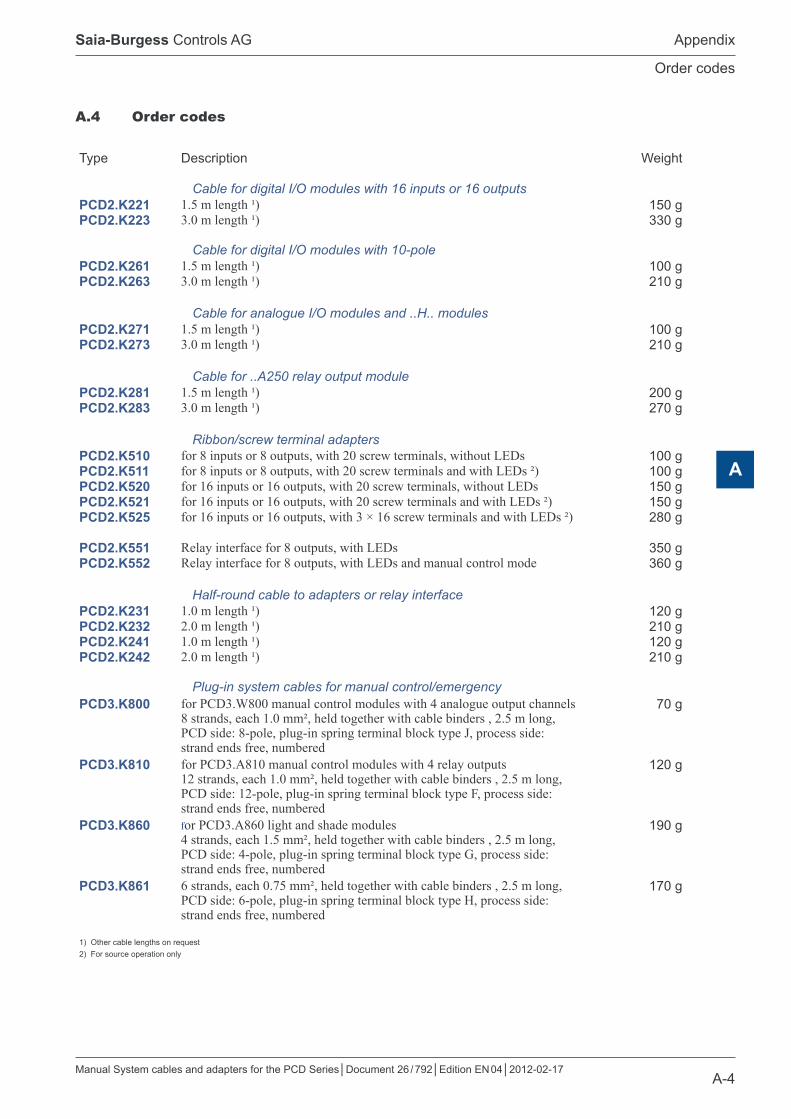
Type Description Weight
Cable for digital I/O modules with 16 inputs or 16 outputsPCD2.K221 1.5 m length ¹) 150 gPCD2.K223 3.0 m length ¹) 330 g
Cable for digital I/O modules with 10-polePCD2.K261 1.5 m length ¹) 100 gPCD2.K263 3.0 m length ¹) 210 g
Cable for analogue I/O modules and ..H.. modulesPCD2.K271 1.5 m length ¹) 100 gPCD2.K273 3.0 m length ¹) 210 g
Cable for ..A250 relay output modulePCD2.K281 1.5 m length ¹) 200 gPCD2.K283 3.0 m length ¹) 270 g
Ribbon/screw terminal adaptersPCD2.K510 for 8 inputs or 8 outputs, with 20 screw terminals, without LEDs 100 gPCD2.K511 for 8 inputs or 8 outputs, with 20 screw terminals and with LEDs ²) 100 gPCD2.K520 for 16 inputs or 16 outputs, with 20 screw terminals, without LEDs 150 gPCD2.K521 for 16 inputs or 16 outputs, with 20 screw terminals and with LEDs ²) 150 gPCD2.K525 for 16 inputs or 16 outputs, with 3 × 16 screw terminals and with LEDs ²) 280 g
PCD2.K551 Relay interface for 8 outputs, with LEDs 350 gPCD2.K552 Relay interface for 8 outputs, with LEDs and manual control mode 360 g
Half-round cable to adapters or relay interfacePCD2.K231 1.0 m length ¹) 120 gPCD2.K232 2.0 m length ¹) 210 gPCD2.K241 1.0 m length ¹) 120 gPCD2.K242 2.0 m length ¹) 210 g
Plug-in system cables for manual control/emergencyPCD3.K800 for PCD3.W800 manual control modules with 4 analogue output channels
8 strands, each 1.0 mm², held together with cable binders , 2.5 m long, PCD side: 8-pole, plug-in spring terminal block type J, process side: strand ends free, numbered
70 g
PCD3.K810 for PCD3.A810 manual control modules with 4 relay outputs 12 strands, each 1.0 mm², held together with cable binders , 2.5 m long, PCD side: 12-pole, plug-in spring terminal block type F, process side: strand ends free, numbered
120 g
PCD3.K860 for PCD3.A860 light and shade modules4 strands, each 1.5 mm², held together with cable binders , 2.5 m long, PCD side: 4-pole, plug-in spring terminal block type G, process side: strand ends free, numbered
190 g
PCD3.K861 6 strands, each 0.75 mm², held together with cable binders , 2.5 m long, PCD side: 6-pole, plug-in spring terminal block type H, process side: strand ends free, numbered
170 g
1) Other cable lengths on request2) For source operation only

Manual System cables and adapters for the PCD Series│Document 26 / 792│Edition EN 04│2012-02-17
Saia-Burgess Controls AG Appendix
A-5
Address of Saia-Burgess Controls AG
A
A.5 Address of Saia-Burgess Controls AG
Saia-Burgess Controls AGBahnhofstrasse 18 CH-3280 Murten / Switzerland
Tel: +41 26 672 72 72 Fax: +41 26 672 74 99
E-mail: [email protected] Home page: www.saia-pcd.com Support: www.saia-support.com
Postal address for returns from customers of the Swiss Sales office:
Saia-Burgess Controls AG Service Après-Vente Bahnhofstrasse 18 CH-3280 Murten / Switzerland