25144688 pyrox heating and ventilation tutorial
TRANSCRIPT

Heating and Ventilation Tutorial
Heat. Vent.Tutorial forside 17-07-98 13:59 Side 1

________________________________________________________________________1
TABLE OF CONTENTS
VENTILATION1. UNITS, FORMULAE, CONVERSIONS 22 HEATING AND COOLING 33. HEAT RECOVERY 54. MOLLIER DIAGRAM FOR HUMID AIR 75. VENTILATION PRINCIPLES 86. FANS 137. ACOUSTICS 168. COMFORT CRITERIA 229. VENTILATION OF VARIOUS AREAS 2410 ELECTRICITY 29
HEATING11. BUILDINGS`POWER REQUIREMENT FOR HEATING 3212. BUILDINGS' ENERGY REQUIREMENTS 4013. RADIANT HEAT 4314. AIR CURTAINS 5315. FAN HEATERS 5716. CONVECTION HEATERS 6017. REGULATING TEMPERATURE 6118. APPENDIX 63

________________________________________________________________________2
1. UNITS, FORMULAE, CONVERSIONS Pyrox
1.1 FORMULASYMBOL DENOMINATION SI UNIT
V volume m3
P,Q effect, output W-j/s-Nm/sCp specific heat
capacitykJ/kg°C
W energy J-Nm-wsh(i) enthalpy kJ/kgt time sv velocity m/sL volume flow m3/s-l/sd density kg/ m3
P pressure N/m2-Pa P pressure diff. N/m2-PaF force NI electric current AU electric voltage VT temperature °C-K T temp. diff. °C-Km length mA area/surface m2
F frequency Hzk thermal
transmit-tancecoefficient
W/ m2 °C
a heattransmissioncoefficient
w/ m2 °C
l thermal conduc-tivity coefficient
W/ m2 °C
1.2 Conversion factors
POWER1 kW = 1,360 hp 1 hp = 0.736 kW1 kW = 860 kcal/h 1 kcal/h = 1.163 x 10⁻³
kW
ENERGY1 kJ = 0.239 kcal 1 kcal = 4.187 kJ
ENTHALPY1 kJ/kg=0.239kcal/kg
1 kcal/kg = 4.187 kJ/kg
SPECIFIC HEAT CAPACITY1 kJ/kgº C = 0.239 kcal/kgº C1 kcal/kgº C = 4.187 kJ/kgº C
FORCE1 N = 0.102 kp 1 kp = 9.807 N
PRESSURE1 Pa = 0.102 mmH2O
1 mm H2O = 9.807 Pa
1 bar = 1,020 kp/cm2 1 kp/cm2 = 0.981 bar
VOLUME FLOW1 m3/s = 3,600 m3/h 1 m3/h =
0.278 x 10⁻³ m3/s
1.3 Example with calculation of effect
In our case, the most relevant units forcalculating effect are m3/s and kW.The following formula is often used tocalculate effect:Q = 0.3 x T x L [ kcal/h]0.3 - kcal/m3
L - m3/h
This formula applies at roughly 20º C and isactually as follows:Q = L x c x d x tc - specific heat of air 0.24 kcal/kgº Cd - specific weight kg/m3
d - 1.293 at 0º C and 1.205 at 20º C
According to the SI system:1 kJ = 0.239 kcalQ = 0.24 x 1.2 x L x t [ kW at 20º C] 0.239L = m3/sQ = L x 1.2 x t
L = m3/hQ = L x 1.2 x t [ kW at 20º C] 3,600

________________________________________________________________________3
2 HEATING AND COOLING Pyrox
1.2.1 HEATING COILWhen a certain volume of air passes a heatingcoil, air temperature is increased from t1 to t2.This process takes place at constant airhumidity. The effect of the heating coil iscalculated as follows:
Q = L . 1.2 .∆t [kW], where:
L = air flow rate, [m3/s]∆t = increase in temperature across the coil,[º C]Example on calculation of required heating coileffect:t1 = 0°C, RH = 50%t2 = 20°CL = 1.4 m3/sQ = 1.4 . 1.2 . 20 = 34 kW
The process is shown in the Mollier diagram:
tt
t
X
2
1
RH=50%
RH=100%
THE PROCESS IN THE MOLLIER-DIAGRAM
Air velocityThe air velocity across the heating coil iscalculated as follows:
L
v = L [m/s], where: V = A AL = air flow rate m3/sA = gross area m2
Water volumeTo calculate pressure drop on the water sideof the heating coil and determine the size ofthe shunt valve, the water volume in a heatingcoil must be given.
This is calculated as follows:q = Q [kg/s], where
Cp.∆t
Q = heating coil effect, [W]t = temperature increase of water through theheating coil, [°C]Cp = 4.175 j/kg°C at a water temperature of50°C
2.2 COOLING COILIn calculating the required cooling effect, it isimportant to consider that part of the effect isused to separate the water (latent heat) andthe remaining effect to lower the airtemperature (sensible heat). It is thereforenecessary to incorporate enthalpy differencesin the calculations to absorb the latent heatpart. The cooling effect is calculated asfollows:
Q = L . 1.2 . ∆t [kW], where:L = air flow rate, [m3/s]h = enthalpy difference for air through the coil,[kJ/kg]
Example on calculation of cooling coil effect:L = 1.4 m3/st1 = 25º C, RH = 50%t2 = 12º C, RH = 100%
t t1 2
CALCULATION OF COOLING COIL EFFECT
Enthalpy can be obtained from tables orsimply from a Mollier diagram:h1 = 50 kJ/kgh2 = 33 kJ/kgQ = 1.4 . 1.2 . (50 - 33) = 28.56 kW

________________________________________________________________________4
The process is illustrated in the Mollierdiagram, from which the separated volume ofwater x and the distribution of latent andsensible heat can be derived.
t
h
t
tX
1
2
h 1
2
RH=50%
RH=100%
THE PROCESS IN THE MOLLIER-DIAGRAM
Latent heat
Sensitive heat
Dx
________________________________________________________________________5
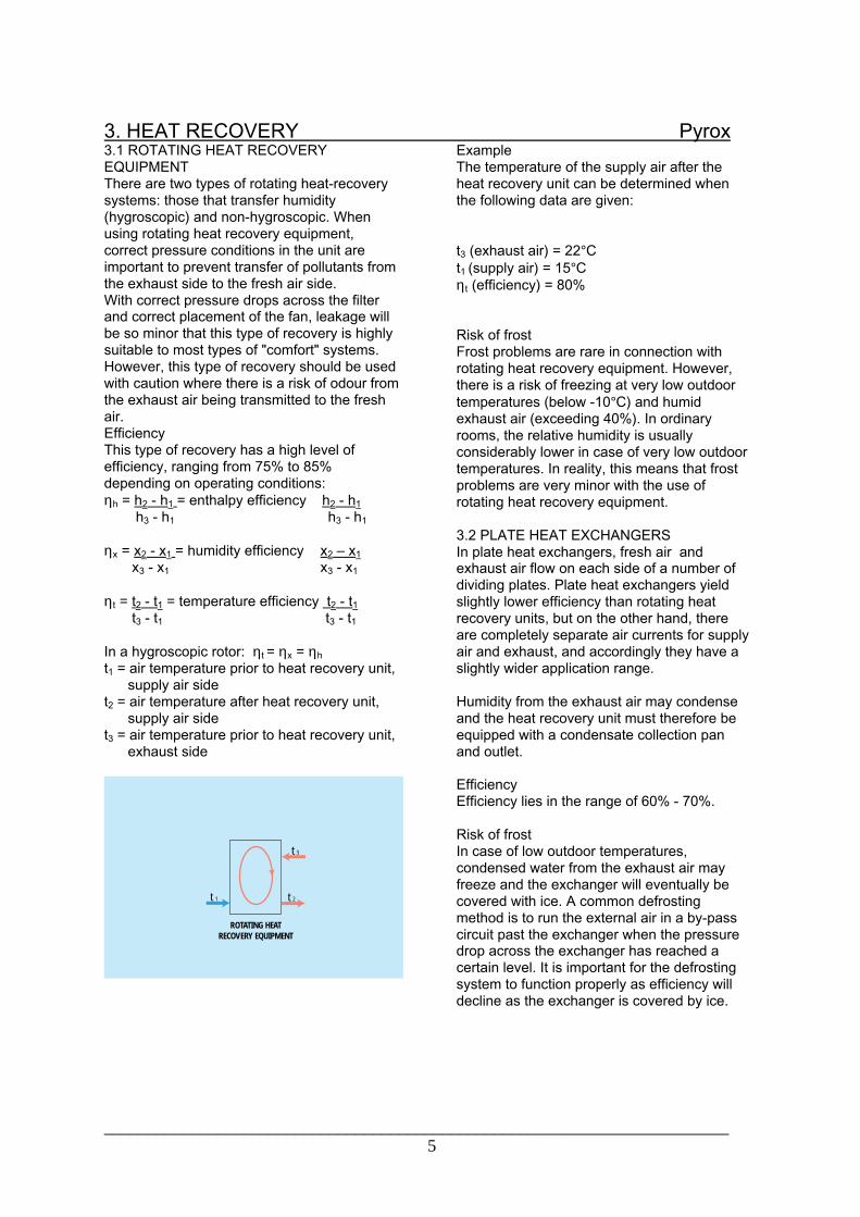
3. HEAT RECOVERY Pyrox3.1 ROTATING HEAT RECOVERYEQUIPMENTThere are two types of rotating heat-recoverysystems: those that transfer humidity(hygroscopic) and non-hygroscopic. Whenusing rotating heat recovery equipment,correct pressure conditions in the unit areimportant to prevent transfer of pollutants fromthe exhaust side to the fresh air side.With correct pressure drops across the filterand correct placement of the fan, leakage willbe so minor that this type of recovery is highlysuitable to most types of "comfort" systems.However, this type of recovery should be usedwith caution where there is a risk of odour fromthe exhaust air being transmitted to the freshair.EfficiencyThis type of recovery has a high level ofefficiency, ranging from 75% to 85%depending on operating conditions:ηh = h2 - h1 = enthalpy efficiency h2 - h1
h3 - h1 h3 - h1
ηx = x2 - x1 = humidity efficiency x2 Ð x1
x3 - x1 x3 - x1
ηt = t2 - t1 = temperature efficiency t2 - t1 t3 - t1 t3 - t1
In a hygroscopic rotor: ηt = ηx = ηh
t1 = air temperature prior to heat recovery unit, supply air sidet2 = air temperature after heat recovery unit, supply air sidet3 = air temperature prior to heat recovery unit, exhaust side
t 3
t 2t 1
ROTATING HEATRECOVERY EQUIPMENT
ExampleThe temperature of the supply air after theheat recovery unit can be determined whenthe following data are given:
t3 (exhaust air) = 22°Ct1 (supply air) = 15°Cηt (efficiency) = 80%
Risk of frostFrost problems are rare in connection withrotating heat recovery equipment. However,there is a risk of freezing at very low outdoortemperatures (below -10°C) and humidexhaust air (exceeding 40%). In ordinaryrooms, the relative humidity is usuallyconsiderably lower in case of very low outdoortemperatures. In reality, this means that frostproblems are very minor with the use ofrotating heat recovery equipment.
3.2 PLATE HEAT EXCHANGERSIn plate heat exchangers, fresh air andexhaust air flow on each side of a number ofdividing plates. Plate heat exchangers yieldslightly lower efficiency than rotating heatrecovery units, but on the other hand, thereare completely separate air currents for supplyair and exhaust, and accordingly they have aslightly wider application range.
Humidity from the exhaust air may condenseand the heat recovery unit must therefore beequipped with a condensate collection panand outlet.
EfficiencyEfficiency lies in the range of 60% - 70%.
Risk of frostIn case of low outdoor temperatures,condensed water from the exhaust air mayfreeze and the exchanger will eventually becovered with ice. A common defrostingmethod is to run the external air in a by-passcircuit past the exchanger when the pressuredrop across the exchanger has reached acertain level. It is important for the defrostingsystem to function properly as efficiency willdecline as the exchanger is covered by ice.

________________________________________________________________________6
Pyrox
3.3 LIQUID COIL HEAT EXCHANGERSHeat exchange using liquid coils is a fluid-related heat recovery system with heating(cooling) coils in the exhaust and fresh airducts, respectively. One of the advantages ofthis system is that exhaust and fresh air ductsdo not need to be combined. The coils can, forexample, be located in the attic and basementrespectively. A frost medium, usually a mixtureof ethylene-glycol and water, is circulatedthrough the piping system.
EfficiencyEfficiency lies in the range of 50% - 60%.
Risk of frostThe percentage of glycol should be roughly30% to ensure that the liquid mixture does notfreeze. At low outdoor temperatures (below -10°C), the exhaust coil may freeze. A commonmethod of defrosting the coil is to stop thecirculation pump in the fluid circuit when thepressure drop in the coil has increased by50% for example.Defrosting only takes a few minutes.
Circulation pumpIf a circulation pump is selected, pressure canbe increased by about 10% and the volume ofwater/glycol by about 30% compared to awater system only.
3.4 HEAT-PIPE HEAT EXCHANGERA heat-pipe heat exchanger is a closed pipingsystem with a self-circulating cooling medium,where liquid evaporates in the hot part of thepipe. The vapour flows over to the cold side(fresh air side), where it is condensed. Theadvantage of this type of heat exchanger isthat it can be applied at high temperatures.
EfficiencyEfficiency lies in the range of 50% - 80%.
________________________________________________________________________7
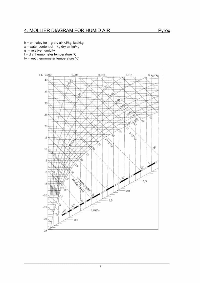
4. MOLLIER DIAGRAM FOR HUMID AIR Pyrox
h = enthalpy for 1 g dry air kJ/kg, kcal/kgx = water content of 1 kg dry air kg/kg¿ = relative humidityt = dry thermometer temperature °Ctv = wet thermometer temperature °C

________________________________________________________________________8
5. VENTILATION PRINCIPLES Pyrox
5.1 AIR QUALITY CONCEPTSIn ventilating various premises, it is normal todifferentiate between two principles: ventilationby diffusion and ventilation by displacement.Before taking a closer look at these two typesof ventilation, the most common air qualityterms should be defined:
Ventilation efficiencyVentilation efficiency is a measure of how fasta pollutant can be removed from a room. It isdefined as the relation between theconcentration of pollution in the exhaust airand the concentration of pollution in the room.
εm = ce. 100% where:
cm
ce = Concentration of pollution in the exhaustaircm = Mean concentration of pollution in theentire roomVentilation efficiency is a frequently usedparameter to evaluate a system's ability toprovide good atmospheric comfort. ε mdepends on the geometry of the room, locationof the valve and distribution of pollution in theroom.With ventilation by displacement, it is possibleto achieve ventilation efficiency exceeding100%, while the goal with ventilation bydiffusion is to achieve εm of about 100%.
Air-change efficiencyAir-change efficiency is a measure of how fastthe air in a room is replaced. It depends on thedistribution of air in the room, i.e. location andsize of valves, room geometry, location of heatsources, etc.
εa = τ n . 100% where:
2 .τm
τn = volume of fresh air supplied/room volumeτm = average "age" of air in the room
With ventilation by displacement, it is possibleto achieve εa of between 50% and 100%, whilefull ventilation by diffusion yields εa ofapproximately 50%.
5.2 Ventilation by displacementVentilation by displacement is a ventilationform that has traditionally been applied forventilation of industrial premises. It can also beused to advantage for many types of so-calledcomfort ventilation. If properly dimensioned, it
can remove major heating effects and achievea high degree of ventilation efficiency. Beforethis principle is described in further detail, thefollowing terms should be defined:
Occupied zoneThe occupied zone is that part of the roomnormally occupied by people. For offices,schools, etc., it is normal to calculate with adistance of 0.5 m from an outer wall withwindow, 0.2 m from other walls and 0.1 m - 1.8m above floor level.
OCCUPIED ZONE
Near zoneThis denotes the zone near a low-impulsevalve where there is a floor draft. Velocity v =2.0 m/s is used as the draft limit for a low-impulse valve in a comfort system. The goal isto achieve the smallest possible near zone fora low-impulse valve.
With ventilation by displacement, the supplymechanism is located at a low level, and air issupplied directly to the occupied zone at a lowvelocity. Convection flows from potential heatsources give the air an upward motion and thehot/polluted air is removed via exhaust valveslocated at the ceiling.

________________________________________________________________________9
Pyrox
Air is supplied to the occupied zone at atemperature of 1 - 5°C below the roomtemperature. It is important that thetemperature is not too low below the roomtemperature since this will yield a so-calledconvection draft from the cold surface.Temperatures of more than about 2°C belowthe room temperature place specialrequirements on the air-supply fittings.
Properly designed systems for ventilation bydisplacement yield air of very good quality.However, the principle has obvious restrictionssuch as:
* The supply valves are large and require a lotof wall space* The supply valves are often covered* The near zone, where velocity exceeds0.2 m/s, becomes too large* The vertical temperature gradient becomestoo large; should not exceed 2-3°C.
It should also be mentioned that several heatsources at various levels and with differenttemperatures complicate matters. Combinedwith movement in the room, this causesdisplacement of air from the upper layer to thelower zones. In practice, this will lead to"ventilation by diffusion."
Ventilation of auditoriumsA common method of supplying air toauditoriums is to supply air under the seats inthe belief that the air will float slowly upwards,thus achieving a displacement effect. This isnot correct however. The air behaves likewater and "flows" downwards where it collectsbefore it flows slowly upwards towards the rearoutlet. The supply air mechanisms could justas easily be installed at the front of theauditorium.Regardless of the location of supply airmechanisms, experience shows that is difficultto achieve any real displacement effect.Measurements and computer simulations for asolution as outlined above indicate aventilation efficiency of roughly 100%, whichentails complete agitation of the air.
Tests have also been carried out for traditionalventilation with (vortex) diffusers in the ceiling.This works satisfactorily, provided the outlet islocated towards the rear. Locating the outlet inother spots may easily result in full short-circuiting.
Suggestions for sensible ventilation ofauditoriums:
VENTILATION OF AUDITORIUMS
1. Ventilation by diffusion with air suppliedfrom the ceiling/rear by, for example, vortexdiffusers. Outlet at the rear.
VENTILATION OF AUDITORIUMS
2. Diffuse supply of air under or in front ofseats. Supply of air beneath the seats has notother significance except that it is oftenpractical to use the space below the seats as asupply chamber.
VENTILATION OF AUDITORIUMS
3. In addition to the above, the rear of theauditorium should be ventilated separately.This is particularly the case when it serves asan entrance area so that users are not met bya "wall" of hot, polluted air.

________________________________________________________________________10
Pyrox
Design of the supply air systems in ventilationby displacement
For displacement-type ventilation at premiseswith normal heat sources in the form ofpeople, light, etc., experience shows that thetemperature change between floor and ceilingis roughly as shown in the figure below:
t i
0.1
Hm
Room
heigh
t
1.1m Dt o
Dt tot
t °Ct g t ut R
TEMPERATURE CHANGE BETWEEN FLOOR AND CEILING
tu = temperature at ceiling, °Cti = supply air temperature, °CQ = addition of heat in the room, WL = amount of air supplied, kg/scp = specific heat capacity of air, 1,000Ws/kg°C
In the following, the conditions when heat isadded in the form of pollution are reviewed.The temperature difference between floor andceiling is given by:
∆to = tg - ti, where:
tg = temperature 0.1 m above floor levelti = supply air temperature
Depending on the type of supply airmechanism, this yields:
∆to = K . ∆ttot
K = 0.25 for supply air mechanisms with lowinduction, such a filter mat or perforated plateK = 0.50 for supply air mechanisms with highinduction.Furthermore:
∆ttot = tu - ti =
ExampleThe following data have been specified for anoffice:Floor area 10 m2
Surplus heat 500 WHeight to ceiling 2.7 mSupply air mechanism K = 0.5The vertical temperature gradient must be lessthan 3°C per ma) Volume of supply air 5 m3/h per m2
b) Volume of supply air 10 m3/h per m2
c) Volume of supply air 15 m3/h per m2
Case a:
∆ttot = 500 = 30°C 50 . 1.2 . 1,000 3,600
∆to = 0.5 . 30 = 15°C
This yields a vertical temperature gradient of15/2.6 = 5.8°C per m, which is too high.
Case b:
∆ttot = 15°C
∆to = 0.5 . 15 = 7.5°C
This yields a vertical temperature gradient of7.5/2.6 = 2.88°C, which is satisfactory withrespect to the requirement.
Room temperature is often defined as thetemperature 1.2 m above floor level. If in thiscase there is a supply air temperature of 15°C,the temperature at the outlet becomes 30°C,and 0.1 m above floor level, the temperaturebecomes 15 x 7.5 = 22.5°C. Furthermore:
∆tR = tg + 1 . (tu - tg) 2,6
∆tR = 22.5 + 1 . (30 - 22.5) = 25.4°C 2,6
This is usually an acceptable maximumtemperature.
pCL
Q
?∆ttot = tu - ti =

________________________________________________________________________11
Pyrox
Case cIf the supply air flow rate is increased to 15m3/h, the temperature gradient becomes1.9°C/m and the room temperature 1.1 mabove floor level becomes 21.9°C.These are excellent conditions.If the supply air temperature is increased to17°C, the temperature gradient remains thesame as before.The room temperature rises to 24°C, which isadequate in most cases.
In conclusion, it is possible to say that 15 m3/hper m2 yields excellent conditions.Since outdoor temperatures during summeronly rise above 17°C a few days of the yearmost places in Norway, artificial cooling is notnormally required.
Proposed ventilation for industrial premisesVentilation by displacement is well suited toindustrial premises with substantial pollutionand high heat loads.The measurement of dust concentrations inwelding shops with displacement-typeventilation indicates that the dust content of airat floor level is 1/3 of the dust content underthe ceiling.
y
COANDA EFFECT
5.3 VENTILATION BY DIFFUSIONVentilation by diffusion involves the injection ofone or several air jets outside the occupiedzone. The jet absorbs large amounts of indoorair and the velocity gradually decreases. Theoccupied zone lies in the return flow and thevelocity here is about 0.7 times the finalvelocity of the jet. In practice, there is often acombination of the aforementioned conditions.Definition of terms:
Coanda effectIf an supply valve is installed sufficiently near asurface, the air jet will cling to the surface. Airbetween the surface and the jet is carriedalong, and since new air cannot flow fromabove, a slight under-pressure occurs at thesurface and the jet is subjected to an upwardmotion. For the jet to cling to the surface, Ymust not exceed 30 cm.
y
COANDA EFFECT
Air throw l0.2
Air throw is defined as the distance from thediffuser to the point in the jet where centralvelocity has dropped to 0.2 m/s. Examples onhow large the air throw should be for typicalinjection valve locations are shown below:Rear injection l0.2 = 0.7 LInjection from ceiling l0.2 = 0.5 L
L
H
VENTILATION BY DIFFUSION

________________________________________________________________________12
Pyrox
Indoor air velocitySuitable air velocity in the occupied zonedepends on such conditions as activity,cladding and air temperature. Empirical dataindicate that draft can be avoided in thetemperature range of 20 - 22°C if the airvelocity is less than 0.18 m/s.
InductionA diffuser's ability to mix indoor air with the airjet from the diffuser.As an example, a high degree of inductionwhen supplying air at temperatures belowroom temperature is favourable in avoidingdraft problems.
Jet drop in case of obstructionThe change of direction of air jets under theceiling when obstructed by girders, lightfittings, etc. Lights must be installed at adistance from the ceiling to maintain a Coandaeffect.

________________________________________________________________________13
6. FANS Pyrox
The fan is an important part of any system fortransportation of air and gas.Some of the central points regarding fanproperties are reviewed below.
The most common wheel shapes are:1) Radial wheel2) Francis wheel3) Screw wheel4) Axial wheel/propeller wheel
b>90°
Forward-curved blades
b=90°
Straight radial blades
b<90°
Backward-curved blades
WHEEL SHAPES
The wheels in groups 2 and 3 have bladeswith double-curved surfaces which increasesproduction costs. Wheels in groups 3 and 4are therefore the most common. Fans in group1 have backward-curved blades, straightblades or forward-curved blades.
Fan characteristicsThe fan characteristic that denotes thecorrelation between a fan's supply of air inm3/s and total pressure increase in Pascal(Pa) can be illustrated with a diagram.Depending on the wheel shape, the fancharacteristics will vary according to the angleof the blades.The actual characteristic will deviate becauseof losses as shown in figure 6.2.
b>90°
b=90°
b<90°
Pa
m /s3
FAN CHARACTERISTICS
L10 x
Pt
Pd

________________________________________________________________________14
The characteristics of fans with backward-curved and forward-curved blades,respectively, are roughly as shown in figure6.3.
Pa
m /s3
Backward-curved blades
Forward-curved blades
(drum wheel)
FANS WITH BACKWARD-CURVED BLADES AND FORWARD-CURVED BLADES
Choke linesIn addition to the fan characteristics, so-calledthrottle regulation (choke) lines or operatinglines are included in the diagram. These areparabolic, but because a logarithmic axissystem is often used, the choke lines areshown as straight lines. The lines arenumbered from 1 to 10 as shown in fig. 6.4The choke line number (l) can be calculated asfollows:
Pd = dynamic pressure at fan outletPt = the fan's total pressure increase

________________________________________________________________________15
Pyrox
Fan efficiencyThe efficiency is constant along a choke line.Diagrams often show efficiency instead ofchoke lines, fig. 6.4.A fan's efficiency can also be shown as afunction of the choke line number, fig. 6.5.Fans with backward-curved blades have thehighest maximum efficiency, up to 85% andthe operating point should lie within the areabetween lines 1 and 2. Fans with forward-curved blades have a lower maximumefficiency, approximately 70%, and this isachieved in the area between lines 4 and 5,
Pa
m /s3
FAN EFFICIENCY
12
34
5
10
(65%)(75%)
(80%)(85%)
(90%)
thus further to the right in the diagram.
Fan selectionFan selection is based on the calculated totalpressure increase required (sum of pressurelosses) and desired air flow rate per time unit.Normally, the desired operating point can beachieved with several fan sizes. If a small fanis selected, the operating point will lie far to theright of the diagram, fig. 6.4. The result will below efficiency. If a larger fan is selected, theoperating point will lie further to the left of thediagram and greater efficiency will beachieved. The initial cost of a larger fan istherefore often offset by lower operating costs.
Fig. 6.5 shows that fans with forward-curvedblades have higher efficiency at higher chokeline numbers.If because of space problems it is necessaryto choose a small fan (for example inaggregates) that functions at a high choke linenumber, a fan with forward-curved blades willoften be a correct choice.
m /s3
Backward-curved blades
Forward-curved blades
100
80
2 3 4 5
z%

________________________________________________________________________16
7. ACOUSTICS Pyrox
7.1 BASIC CONCEPTSDefinitionsSound is the term for audible pressureoscillation in an elastic medium. The soundpressure oscillates around the atmosphericpressure in a sinus-shaped sound movement,provided the tone is pure.
T
PTidPaSo
und p
ressu
re
Atmosphericpressure
The following values can be defined on thebasis of the above:P = the instantaneous value of the soundpressurePeff = sound pressure efficiencyPeff = Pa/2 - the value registered by soundmetersf = 1/T = frequency (Herz - Hz)c = sound velocity (m/s)= wavelength (m)
Whether a sound is audible to the human eardepends on its frequency and volume. Thehuman ear can hear sounds in the 20Hz -20,000 Hz frequency range.The lowest sound pressure the human ear canperceive lies at 2_105Pa at 1,000 Hz.
Sound that is perceived as undesired oruncomfortable is usually considered NOISE.
Measuring units for noiseSound power (N):The quantity of energy per time unit which isgenerated in the form of sound from a soundsource.
Sound intensity (l):The sound energy per time unit that flowsthrough a flat surface at a right angle to thesound's spreading direction.
Sound pressure (p):
The power the sound exerts on a surface at aright angle to the sound's spreading direction.A logarithmic scale has been introduced toobtain more manageable figures. Thecorrelation between the numeric values on thisscale better express how the human earperceives sounds of various strength. Thesound power level and sound pressure levelare therefore defined as follows:
Sound power level (LW):
N = effect produced by sound sources (W)No = reference effect (W) (10-12W)
Sound pressure level (LP):
p = sound pressure (N/m2 = Pa)po = reference pressure (Pa) (2*10-5Pa)
Different manufacturers operate with differentreferences. It is therefore important for themanufacturer to specify the reference used inpresenting sound data.
Example (fan):The produced sound power from a fan isN = 10-4W
LNref10-12
W = 10 . log ( 10-4) = 10 . log108 = 80dB 10-12
LNref10-13
W = 10 . log ( 10-4) = 10 . log109 = 90dB 10-13
These examples show that results may varydepending on the reference used.
))(log(10 dBNo
N?=
)log(20)log(102
2
Po
P
Po
P ?=?=

________________________________________________________________________17
PyroxNoise criteria NR/dBANR criterion:This specifies the permissible sound pressurelevel as a function of the frequency.dBA criterion:This furnishes the sound meter with an A filterto attenuate sound with frequencies of lessthan 1,000 Hz. There are also B and C filters.An A filter is usually used in connection withventilation.It can often be of interest to determine therelationship between dBA and NR values.This can be calculated roughly as follows:dBA = NR + 5 (dB)
Addition and subtraction of dB valuesExample:There are two sound sources of respectively:LW1 = 40 dB and LW2 = 38 dBThe resulting sound power level can bederived mathematically by logarithmic addition.However, it is more practical to use thediagram below for addition and subtraction ofdB values, respectively. As can be seen fromthe diagram, a sound level of LWR = 42 dBresults from the two sound sources.
ADDITIONDifference to be added to the highest dB valueDifference between dB values to be added
SUBTRACTIONValue to be subtracted from the highest dBvalue Difference between dB values to besubtracted
7.2 SOUND POWER AND SOUND PRESSURE LEVELThe connection between sound power leveland sound level
Sound power:This is independent of the location of themeasuring point and the characteristics of thesurroundings.
Sound pressure:This decreases with increasing distance to thesource. It depends on the room's acousticproperties.
Note: If the sound pressure level has beenspecified, additional information is required onthe acoustic properties of the room where themeasurements were taken. To avoiduncertainties with respect to the interpretationof sound data, it is therefore more appropriatethat the manufacturer specifies the soundpower level for his equipment.Sound measurements normally entailrecording the sound pressure level. It istherefore necessary to be aware of theconnection between sound power level andsound pressure level. The total sound picturein a room is affected by the location andopening cross section of the sound source, aswell as the room surfaces' ability to absorb orreflect sound.In addition, direction factor Q can be definedas a function of the size of the valve's crosssection, the measuring point's locationcompared to the opening cross section, thevalve's location in the room and, finally, thefrequency at which the sound is measured. Itis then possible to set up the followingcorrelation between sound pressure level LP
and sound pressure level LW:
LP = LW + 10 . log ( Q + 4 . n) 4πr2 RThe Q/4πr2 fraction represents the directsound from the sound source, while 4/Rrepresents the reflected sound.r = distance from sound source to measuringpointQ = directional factorR = room constant

________________________________________________________________________18
Pyrox
The room constant R is an expression of theroom's acoustic properties and can be definedas follows:
R = A [m2Sabine] 1_αA = the room's absorption (m2Sabine) = mean absorption coefficient of the room
The following is normally understood byabsorption coefficient:
α = la + lt li
I = sound energy emittedIt = energy that penetrates the wallIa = energy that is absorbed by the wall
For an infinitely hard wall: = 0For an open window: = 1
This implies that the absorption coefficient willlie between 0 and 1.
The table below shows some typical meanvalues for Ð, depending on type of room:
Type of room a
Sound studio, musicrooms
0.30-0.45
Housing, offices, hotelrooms, conferencerooms
0.10-0.15
Classrooms, hospitalrooms
0.05-0.10
Factories, indoorswimming pools
0.03-0.05
Value A has previously been defined as theroom's absorption. This value is derived fromthe product of surface F and absorption factor_. This value is thus called the room'sabsorption and is actually measured in m2. Toemphasise that an acoustic value is involved,m2Sabine is used.
Near zone and reverberation fieldThe distance from a sound source to a pointwhere direct sound and reflected soundequally contribute to the resulting soundpressure level is given by:
Near zoneAt r <r1, the direct sound dominates and little isachieved by altering the room's acousticproperties.
Reverberation fieldWhen r>2 x r1 , the sound pressure ispractically independent of the distance, andonly the reflected sound has any impact.
Reverberation timeThis is the time it takes for the sound pressureto drop to 60dB after the sound source hasbeen switched off.
Rooms with several sound sourcesIt is of interest to note how conditions developin a room with several sound sources. As anexample, it is quite common to have severalventilation apertures in one room. As a firststep, it is then necessary to specify where inthe room measurement will take place.Only the direct sound then affects one of thevalves, while the others contribute reflectedsound. The correlation between soundpressure level and sound power level can thenbe written as:
LP = LW + 10 . log ( Q + 4.n) 4πr2 R
n = number of valves
RQrRr
Q ??=?= 14,04
4 12π

________________________________________________________________________19
Pyrox
Calculation exampleA suitable valve to supply air to a room is to beselected. You have the choice of a valve fromPyrox or a valve from another manufacturercalled X. A comparison of the two with respectto sound is to be performed.
Sound level requirement for the room:NR30 (or close to 35 dBA)
According to manufacturer X's catalogue, thesound pressure level is 30 dBA for theapplicable air flow rate. It is further stated thatthis value applies to the reverberation field of aroom corresponding to 10 m2Sabine.For Pyrox's valve, a sound power level of 32dBA is quoted for the corresponding air flowrate.
Unless you know the correlation between, andimportance of, sound pressure level andsound power level, it is easy to be misled intobelieving that manufacturer X's valve has alower sound level than the correspondingPyrox valve. As will be demonstrated, thecircumstances are a bit more complex.
The sound data specified for manufacturer X'svalve apply to a room with a clearly definedmeasuring point and clearly specified acousticproperties. Before the valves can becompared, the specified sound value must beconverted to a form where it is independent ofthe measuring point and acoustic properties ofthe room. It is therefore necessary to calculatethe sound power level of the valve.
LW = LP - 10 . log ( Q + 4) 4πr2 R
The first fraction within the parenthesis equals0, since measurement was performed in thereverberation field. Furthermore, R_A = 10m2Sabine since this is a relatively hard room,so that Ð can be set at approximately 0. Thiswill subsequently yield:
LW = 30 x 4 = 34 dBA
Accordingly, a sound pressure level of 30 dBAcorresponds to a sound power level of 34 dBAfor manufacturer X's valve. The sound datafrom both manufacturers are now available ina general form and it can be noted that in thiscase the Pyrox valve came out ahead.However, to determine whether the valvesmeet the specified sound requirement, it isnecessary to calculate sound pressure on thebasis of the sound power level for the actualroom where the valve will be located. In thiscase, the following data have been specified:
Room constant R: 38 m2SabineDirection factor Q: 2 (generally applies to
ceiling-mountedvalves)No. of valves: 2Measuring point: The soundrequirement
applies to 1 m belowone of the valves
The actual sound pressure level using a Troxvalve in the relevant room can now becalculated as follows:
LP = 32 + 10 . log ( 2 + 4.2) =28dBA 4πr2 38
This shows that the valve for the room inquestion ends up well below the 35 dBArequirement. Furthermore, it is important tonote that it is not possible to compare sounddata from various manufacturers unless themanufacturers operate with the samereferences.
As a general guideline in comparing thespecified sound data for Pyrox valves withvalves for which the sound pressure level isspecified at 10 m2Sabine, 4 dbA can besubtracted from the specified sound powerlevel to obtain the sound pressure level andthus obtain comparable values.

________________________________________________________________________20
Pyrox
7.3 Sound reductionSound reduction can basically be achieved intwo ways: by absorption and by reflection.There are various stages of sound reductionin a ventilation plant, including:
* Sound reduction in straight ducts* Sound reduction in ducts with internal sound insulation* Sound reduction in bends and branch ducts* Sound reduction in connection with exhaustinto the chamber* Sound reduction through changes in cross-section* Sound reduction through end reflection. Atthe point where a duct enters a room, part of the sound is reflected back to the duct. This actsas a sound reduction for the room.* Sound reduction through room absorption. The difference between LW - LP can be considered as a sound reduction due to roomabsorption.* Sound reduction through sound absorbers. Ifthe natural attenuation in a system is notsufficient, sound absorbers must be added.
The degree of sound reduction as a result ofthe aforementioned stages can usually bederived from tables, diagrams and themanufacturer's data.The following will examine sound reduction inducts with internal insulation since this asimple method of reducing noise. Soundreduction can roughly be estimated as follows:
D = K . O . α1.4 [db/m] A
K = correction factor, approx. 0.7 at 250 HzO = absorbing circumference (m)A = free duct area_ = absorption coefficient
Q/A will vary with the shape of the valve'scross section, and sound reduction can beenhanced if the cross section is divided intoseveral ducts. This phenomenon serves as abasis for inserting so-called bafflers in soundabsorbers to enhance sound reduction.
7.4 Sound calculationsSound calculations to determine the requiredsound reduction in the main sound absorberinstalled after a fan or, for example, after adamper. As a basis, use the room assumed tobe most exposed. This is usually the room withthe shortest main duct stretch from the fan tothe room. The following sound calculationsmust then be performed item-by-item asshown in the example below for an injectionsystem.
1. Use the room's permissible sound pressurelevel from the injection system as a basis.
2. First, check that the selected valves meetthe requirement of item 1. If this is in order,proceed to the next item.
3. The permissible sound pressure level fromthe duct system can now be determined bysubtracting the value of item 2 logarithmicallyfrom the value of item 1. As previously shown,a diagram is used for this purpose.
4. Add sound reduction due to roomabsorption to the value of item 3. (Standardaddition)
5. Add sound reduction due to end reflection tothe value of item 4. (Standard subtraction)
Having now proceeded from the room , pastthe valve and into the duct system, the valueof item 5 corresponds to the permissible soundpower level in the ducts right after the valve(since room absorption has been included).Continue with the following:
6. Sound reduction in the duct, bends,branches, etc. until the sound source isreached.The sum of the values in 5 and 6 (standardaddition) yields the permissible sound powerlevel just after the sound source.

________________________________________________________________________21
Pyrox
7. Find the sound source's sound power levelin the manufacturer's catalogue.
8. The difference between the values in item 7and item 6 yields the sound reduction requiredin the sound absorber.
A calculation as shown above must beperformed for each individual octave band.Sound is normally most critical at frequenciesof 250 Hz and 500 Hz. Accordingly, it usuallysuffices to perform calculations for thesefrequencies.
There is user-friendly software programavailable for these types of calculations,which greatly facilitates the work.

________________________________________________________________________22
8. COMFORT CRITERIA Pyrox
8.1 TOTAL HEAT LOSS PER PERSONDEPENDING ON TYPE OF WORK/ACTIVITY
Activitylevel
Type of activity Total heatloss perperson,estimatedvalue in W
I Working in a sittingposition, such asreading and writing
100
II Light work standing,laboratory work,typing
150
III Moderate physicallabour
200
IV Heavy physicallabour
more than250
8.2 HEAT CONDUCTIVITY RESISTANCE OFCLOTHING
TYPE OF CLOTHING HEATCONDUCTIVITYRESISTANCE,R in m2K/kW
Without clothing 0Light summer clothing 80Medium clothing 160Warm clothing 240
Note: The approximate value of heatconductivity resistance is about r = 160m2K/kW = 1 clo.
8.2 COMFORTABLE INDOOR AIRTEMPERATURE RANGEThe following premises show how humansexperience comfortable indoor temperatures,depending on the outdoor temperature.With increasing outdoor temperatures,increasing room temperatures arerecommended.
CONDITIONS:* Activity levels 1 and 2* Medium to light clothing* Air temperature close to the surfacetemperature of the surrounding surface.
5. INTERNAL AIR TEMPERATURETOLERANCEAir-conditioning plants for ventilation andheating only should not have overall localdeviations in room temperature of more than±2.0K in the horizontal measuring zone of theoccupied area.For air-conditioning plants with cooling, thesedeviations must not exceed ±1.5K, with theexception of impact from heat sources.

________________________________________________________________________23
Pyrox
4. ROOM AIR VELOCITYThe validity of this penetration curve is subjectto the specified conditions.A shift in change of conditions may occur.Accordingly, the overall assumption of a roomair velocity of 0.2 m/s is often incorrect. Todetermine the limit value of air velocity, it isnecessary to be familiar with the room, theroom's functions and the activities of thepeople in the room.
THE CURVE APPLIES FOR:* Activity level 1* Medium clothing* Air temperature close to the surfacetemperature of the surrounding surfaces* With a 50W increase, the critical curve canbe increased by 0.04 m/s* With higher/lower heat conductivityresistance of clothing than 80 m2K/kW, thecritical curve may be transposedcorrespondingly by 0.04 m/s.

________________________________________________________________________24
9. VENTILATION OF VARIOUS AREAS Pyrox
FOR VENTILATION OF VARIOUS AREAS,REFERENCE IS MADE TO THE 1987BUILDING GUIDELINES WHICH STATE:
47:52 PUBLIC BUILDINGS, PROFESSIONALBUILDINGSNecessary ventilation must be calculatedtaking the following factors into account:* human load* pollution from building materials, furnitureand equipment* pollution from special pollution sources
The volume of outdoor air that must besupplied because of pollution is usually thesum of the above items.
* Human loadÐ In rooms occupied by people for lengthyperiods, air must be supplied at a rate ofminimum 7 l/s per person
Ð For rooms occupied by people on and off(e.g. schools, nursery schools), this volume ofair can be reduced according to the time thepremises are occupied.
Ð In rooms with limited user time (assemblyhalls), air must be supplied at a rate ofminimum 4.5 l/s per person.
* Pollution from building materials, furnitureand equipmentBuilding materials, furniture and equipmentgive off odour and other irritating effects, andair must therefore be supplied at a rate ofminimum 0.7 l/s per m2 floor space. This valuehas been established on a somewhatuncertain basis and assumes that acceptable"good" materials are used.This calculation basis also applies to corridors,auxiliary rooms and common areas. High roomtemperatures and unfortunate selection ofmaterials may increase the need for ventilationdue to increased discharge of waste gases tothe internal air.
A temperature of less than 22 ° C isrecommended and has been used as a basisfor the calculations.Experience dictates that emission of wastegas and particles from building materials maynecessitate considerably more air to achievean acceptable dilution. In the first year ofoperation, the air-conditioning plant shouldtherefore run 24 hours per day at full capacity.The same applies after extensive renovation.To avoid a high level of pollution at the start ofthe day's work, the air-conditioning plantshould also run outside of working hours (ifnecessary at reduced capacity or switched onearly enough for the pollution to be sufficientlydiluted before work begins in the premises).
* Pollution from special pollution sourcesExtraction by hoods and/or encasing shouldbe used in areas with special, local pollutionsources to limit dispersion in the room. If it isnot possible to sufficiently limit dispersion, theair flow rate required to dilute the pollutionmust be calculated.
Normally, the air flow rate will depend on thenumber of people. For rooms where thenumber of people cannot be determined in anyother way, the values in table 47:521 can beused as a guideline.To obtain a proper indoor climate, the outdoorair flow rates must be limited in each case onthe basis of pollution in a), b) and c). Table47:522 shows examples of air flow rates in a)and b) for various premises. In addition tomechanical ventilation, there should bewindows that can be opened.The law on protection against the harmfuleffect of tobacco contains regulations that maybe of importance to the design of the air-conditioning plant.As an example, air supply to separate,enclosed offices with air transfer to an exhaustarrangement in the corridor will not beacceptable in buildings where smoking ispermitted in individual, enclosed offices. Inaddition, pollution from tobacco smoke will initself require greatly increased air flow rates,see table 47:522.

________________________________________________________________________25
9. VENTILATION OF VARIOUS AREAS Pyrox
REFERENCE IS ALSO MADE TO THEFOLLOWING GUIDELINES IN THEWORKING ENVIRONMENT ACT ISSUED BYTHE DIRECTORATE OF LABOURINSPECTION:
* Administrative standards for pollution in a working environment
* Climate and ventilation at indoor workplaces
table 47:521
PREMISES No. of people per100 m2 floor space
Assembly halls 150Gymnasiums 30Educational facilities 50Offices 10Sales premises 30Restaurant premises 100
No. of peopleThe number of people (number of people perm2 of floor space in the room) is determinedon the basis of the assumed function of theroom. If the number of people cannot bedetermined in any other way, the values in thetable can be used as a guideline.
Examples of air flow ratesNotes:Air flow rates are specified in litres per secondper person for column a), in litres per secondper m2 floor space for column b), and in litresper second per shower/WC/urinal for vents. (1l/s 3.6 m3/h).
The figures in column b are based on the useof building materials, equipment and furnitureof acceptable "good" quality with respect toodour and other irritating effects.
Air for showers and washrooms can be takenfrom adjacent rooms if this air is of relativelyhigh quality.
table 47:522PREMISES External air flow rates due to
pollution fromVents
a)people
l/(sp)
b)buildingandfurniture
l/(sm2)
c)specialpollutionsources
l/(s equip)
Offices andpremises forlight andaverage work
7.0 0.7 CopyingWeldingSoldering
Sales premises 7.0 0.7
Educationalpremises andactivity rooms innurseries
5.5 0.7 ChemistryroomsWelding/Soldering
Gymnasiumfacilities
7.0 0.7
Assembly halls 4.5 0.7
Hotel rooms 7.0 0.7
Restaurants 7.0 0.7 Kitchen
Patients'rooms/residentrooms athospital andhealthinstitutions
7.0 0.7
Showers 17
WC, urinals 17
In rooms where smoking is common, theexternal air flow rate should normally be atleast 20 l/s per person.
47:43 HOUSINGThe above evaluations on pollution frombuilding materials, equipment and furniturealso apply to housing.

________________________________________________________________________26
9. VENTILATION OF VARIOUS AREAS Pyrox
47:531 GENERALThere are no requirements with specificfigures for outdoor air supply in connectionwith housing. Ventilation is based on a certainventing, natural or mechanical, from roomswith greater air pollution or humidity loads,such as kitchens, bathrooms and WCs.An outdoor air flow rate corresponding to theoverall venting is supplied to the housing unitvia a separate supply air unit, through outdoorair valves, windows that can be opened,building irregularities, etc.
Total venting from the kitchen, bathroom, WCand laundry room according to table 47:53 willnormally secure an outdoor air flow ratecorresponding roughly to 0.5 air changes perhour. This is considered the minimumrequirement for housing ventilation. See alsounder 47:533.
To always ensure that indoor air of adequatequality, ventilation should be maintained evenwhen the house or rooms are not in use.
For laundry rooms with openings to thekitchen, the ventilation requirements willnormally be met if the kitchen has ventilationas specified for kitchens.
When the basement is partly above ground,the ventilation for basements can be met byvents in several outer walls so that thebasement is provided with a draft.
In housing exposed to radon, it is important forthe ventilation plant to cause as little underpressure as possible. Balanced ventilationshould therefore be used for these houses.See "NBI Building Details, sheet A 520.706Radon" Construction measures/details. ?
Radon is crucial in housing and particularly forthe floor at ground level. In accordance withthe law on municipal health services, thehealth authorities must procure an overview ofhealth-related problems. This also includesradon occurrences, including a duty to makesure radon occurrences are surveyed inconnection with new buildings.
The World Health Organization (WHO), hasrecommended 200 Bq/m3 as the maximumlimit for radon concentration in housing.Concentrations above this limit providereasons for simple measures such as asealing layer against the ground.Concentrations of 800 Bq/m3 should not occur.If this is the case, measures such asventilation of the ground in addition to thesealing layer must be implemented. TheNational Institute of Radiation Hygiene haspublished various information with guidelineson building surveys, measurement in existinghousing and on health hazards and preventivemeasures.
47.532 SUPPLY OF EXTERNAL AIRThe supply of outdoor air to individual roomsshould be adapted to the rooms' outdoor airrequirement and arranged in such a mannerthat it does not create uncomfortable draftproblems.
In buildings with mechanical ventilation,special precautions must be taken to avoidunder pressure in the rooms. Fireplaces andother open hearths that require extensivesmoke suction capacity call for air supply of150-300 m3 per hour (42-84 l/s), whichcorresponds to overall external air vents of atleast 300 cm2, preferably distributedthroughout the various rooms of the house.
47:533 EXHAUST ARRANGEMENTSTable 47.53 gives the recommended ductdiameter, air flow rate, etc. for rooms where anexhaust arrangement is required. For smallerhouses where the sum of the specifiedexhaust air flow rate yields unduly highbackground ventilation, it should be possible toreduce the exhaust air flow rate, provided itcan be increased according to need, e.g.during cooking, taking a batch, etc.
The kitchen should have a suction hood overthe cooker to keep cooking smell fromspreading throughout the building.

________________________________________________________________________27
9. VENTILATION OF VARIOUS AREAS Pyrox
Table 27.53ROOM Natural
ventilationDuct crosssection in cm2
Mechanicalventilation Airvolume rate inl/s
Air supply, valves,diffusers, ducts
Living room,bedroom
- - Window that can be opened and/oradjustable valve with a valve with a freeaperture of 100 cm2 in the outer wall
Kitchen 150 17 As for the living room, or with diffuser above,in or beneath the door from adjacent roomswith an aperture of 100 cm2
Bathroom with/without WC 150 17 Diffuser above, in or beneath the door froman adjacent room, with an aperture of 100cm2
Separate shower or WC 100 11 Diffuser above, in or beneath the door froman adjacent room, with an aperture of 100cm2
Laundry room forindividual apartments
150 22 150 cm2 diffuser/valve from adjacent room150 cm2 adjustable valve in outerwall/window that can be opened and adjusted
Common laundry roomassumed used by:a) one family per dayb) several families perday but notsimultaneouslyc) several familiessimultaneously? per family
30NotrecommendedNotrecommended
3355
44
Duct for supply of external air must have across section that is 80% of the duct sectionrequired for ducts in natural ventilation c)
Basement with windowsthat cannot be opened
3 cm2 pr m2
floor space0.3 l/s perm2 floorspace
Valve cross section of 3 cm2 per m2 floorspace
Lift shaft 50 cm2 perm2 of shaftarea
0.5 l/s perm2 of shaftarea
Cross section for external air supply:50 cm2 per m2 of shaft area
Garbage chute andrelated refuse roomStorage rooms/attics
Exhaust and supply must be designed to avoid under pressure
Adequate ventilation

________________________________________________________________________28
9. VENTILATION OF VARIOUS AREAS Pyrox
47:54 SMALL HOUSES
47:541 GeneralSee guideline for 47.531Reference is made to "NBI Building Details"sheet A 552.304 Ventilation of small houses.Systems and components.
The regulation that mechanical ventilation canbe carried out by a separate fan and duct,freely routed from each room, entails that theexhaust duct above the roof can be eliminatedand replaced by an electrically driven exhaustfan located in the outer wall. This regulationapplies first and foremost to detached houses.For semi-detached houses, and small housesin groups or rows, etc. exhaust through theouter wall can cause annoying smells inneighbouring apartments. As such, this type ofsolution is particularly ill-suited to horizontallydivided houses.
47:55 GARAGESTo achieve efficient airing, air supply andexhaust must be distributed as equally aspossible throughout the premises. Ventingfacilities should be found at both floor andceiling level.
Air transferred from other premises can beused to supply air to garages, provided it is ofadequate quality.
With respect to ventilation of service stations,reference is made to Directorate of LabourInspection regulations.
AS A MINIMUM, GARAGES SHOULD BEVENTILATED AS FOLLOWS:
1. UP TO 50 m2 FLOOR SPACEWith natural ventilation: outdoor air intake andoutlet, each with an area of minimum 2% ofthe floor space.
2. MORE THAN 50 m2 FLOOR SPACE* Garages in rows for 1 row of cars, asspecified in item 1.Other garages should have mechanicalventilation with the following capacity:* Garages for long-term parking of private carsand with persons present less than 1 hour/day:q = 2 x M l/s, but minimum 0.85 l/s per m2 offloor space.
* Other garages:q = 4 x M l/s, but minimum 1.7 l/s per m2 offloor spaceq = air changes in l/sM = exhaust in l/s emitted from engines in thegarage
For private cars, M is calculated according tothe following formula:M = (20+0.1s1)n1+0.1n2s2)1/3.6 l/s wheren1 = number of parking spaces in thegarage/garage section.n2 = number of other parking spaces withentrance and exit through the garage section.s1 = total average driving stretch in meters forthe entrance and exit of a car in thegarage/garage section.s2 = average driving stretch in the garagesection for the entrance and exit of a carwhose entrance and/or exit takes placethrough the garage section.For trucks and buses in garages where thereis no need to count on traffic queues, n1 and n2
are specified as 1/25 of the area of the garagein question.x) A garage may have outer walls and thesemay be arranged in such a fashion that thegarage is sufficiently aired without specialventilation.

________________________________________________________________________29
10 ELECTRICITY Pyrox
1.10.1 Ohm's lawU = R . IP = U . I
U = voltage in V (volts)R = resistance W (ohm resistance)I = current in A (Amperes)P = power in W (Watts)
EXAMPLE:How to control the amperage of anelectric battery, 1 phaseelectric heating power, 3 kWvoltage 230 V
l = P . l = 3,000 = 13.04 A U 230
For three-phase multiply by a factor of 3.
EXAMPLE:How to determine the amperage of a fanmotor:
P = U .I . cosϕ
COS = Loss factor for a motor; the value isalways less than 1.P = 0.25 kWU = 400 VCOSµ = 0.7What is the amperage?
I = 250 = 0.89A 400 . 0.7
EXAMPLE:What is the power?I = 10AU = 400 V400 x 1.73 x 10 = 6920 W
1.10.1 Control of heating equipmentOn/off thermostatsThe simplest and cheapest method ofmaintaining an even temperature in a room tobe heated, is to use a thermostat that sensesroom temperature and switches the hot air fanon or off. See figure
TP
°C
25
24
1
0
ON/OFF THERMOSTATS
An important concept when discussingthermostat control is the dead band. Athermostat that switches on at 24°C andswitches off at 25°C has a dead band of 1°C.A small dead band is often desired since itrepresents stable room temperature. Seefigure
TP
°C
25
24,5
1
0
DEAD BAND
An excessively large dead band can causetemperature fluctuations. Several types ofthermostats are available. Capillary tubethermostats, which exploit the principle thatliquid expands as temperature rises, areaccurate and inexpensive. Electronicthermostats involve slightly higher costs buthave two advantages. They offer theopportunity to set/adjust the dead band with ahigh degree of accuracy. The dead band mustnot be too small when heat is controlled bycontactors. The contactors will switch on andoff at short intervals, leading to wear andnoise.
IUP ??= 3

________________________________________________________________________30
10. ELECTRICITY PyroxMulti-stage thermostatsFor hot air systems with higher power values, switching full power on/off is seldom desired. Thecommon practice is to divide the power into two or several equal parts and switching on as muchpower as required. The simplest way to control a hot air fan is to install a multi-stage thermostatwith three contactors. The thermostat functions in the following manner:When the temperature drops below the set temperature, contactor no. 1 switches on 1/3 power.When the temperature drops further, contactor no. 2 switches on another 1/3. If the temperaturecontinues to drop, contactor no. 3 switches on the remaining power. This yields a smaller networkload during control of higher output and a more even temperature from the hot air system. Theprinciple is shown in figure
TPP
P
P
°C
25
24
23
22
13
2
1
0
1
0
1
0
MULTI-STAGE THERMOSTATS
Program controlFor higher effects/output it is possible to use program connection. The duct coil elements are thendivided into a number of groups. If group 1 is of 1 kW, then group 2 is of 2 kW, group 3 of 3 kWand group 4 of 4 kW. These four power groups yield 7-stage power control. Power can beadjusted according to 1kW stages from 1 to 7 kW.This principle is illustrated in figure
2
2 2
2 2
4
4 4 4 4
3 5 6 71
1
1
1
1
Stage
P
PROGRAM CONTROL
A program controller can be used for control of stationary hot air fans. With this type ofequipment, it is possible to control the power to each apparatus in the system, with up to 12heating stages.Night set-back of room temperature is a standard feature. Program controllers can also bedelivered with functions for control of damper motors in mixing dampers to control outdoor andsurrounding air, respectively.

________________________________________________________________________31
PyroxInfinitely variable temperature controlTemperature controllers of the Pulser type or TTC are often used as an alternative to powercontrol with on/off or 3-stage thermostats. Pulser 220 and TTC use a Triac in the control circuit.Triac is a semi-conductor that can switch power on/off to the electric heating elements without thedisturbing noise which would otherwise occur with contactor-type control. A connection anddisconnection cycle takes one minute or less. Output is increased by increasing the "on" time andreducing the "off" time correspondingly.The power controller is also equipped with a temperature controller and potentiometer. Thetemperature sensor can be of the built-in or external type. Triac controllers cannot be used tocontrol contactors and can therefore not be used for control of control AVR hot air appliances andLPX/LG air gates. On the other hand, they are well suited for control of ceiling-mounted heatersand duct batteries.
1 min
1 min
TEMPERATURE CONTROLLERS
The principle is illustrated in figure

________________________________________________________________________32
11. BUILDINGS`POWER REQUIREMENT FOR HEATING Pyrox
GeneralThe total power requirement for heating a building is determined by three factors:
HEAT LOSS IN A BUILDING
INFILTRATION
VENTILATION
TRANSMISSION
Transmission heat loss is caused by the stream of heat from inside the building going through thebuilding's structure. The greater the difference between indoor/outdoor temperature, the greaterthis heat loss will be. Another determining factor is the building's thermodynamic properties.Generally, efforts are made to reduce this kind of heat loss by insulating the building.
Air infiltration heat loss is due to cold outdoor air seeping in through leaks in the structure of thebuilding. The extent of this type of heat loss is difficult to calculate precisely. Normally empiricaldata is used to calculate this type of heat loss for various types of building.
Finally, heat is required to heat ventilation air, either via direct application of heat to the heatingcoil in a mechanically balanced system, or indirectly to the inside air in a building with naturalventilation.
Heat loss due to transmission
Heat loss will occur through various components of the building such as exterior walls, windows,floors and ceilings. This heat loss can be expressed by the following equation:
Un = total heat transfer coefficient for surface no. n, [W/m2 x K]An = area of surface no. n, [m2]∆T = difference in temperature at the building component, [K]
[ ]WTAU nn ∆??Σ=Φ

________________________________________________________________________33
Pyrox
If we are familiar with the construction of the building, the U factor for a construction consisting ofseveral layers can be calculated using the following equation:
[ ]UR R R R R
W m Ki y n
=+ + + + +
?1
1 2
2
....../
U-FACTOR FOR A CONSTRUCTION
OUT
ROOM
Ri = internal heat transfer resistivity between the air and the building's constructionRy = external heat transfer resistivity between the air and the building's constructionR1..Rn = heat transfer resistivity for each individual material layer
The following values can be used for Ri and Ry in the calculations:
Ri = 0.13 m2⋅ K/WRy = 0.04 m2⋅ K/W
Rn equals the heat transfer resistivity for each individual material used in the building'sconstruction, and is calculated on the basis of Rn = sn/λn where s stands for the thickness of the

________________________________________________________________________34
Pyrox
layer and λ is the material's thermal conductivity. The λ values for most construction materialscan be found in Norsk Standard 3031 (NSÊ3031) as well as in technical manuals.
When we are required to calculate the transmission heat loss for a building in practice, we mustbegin with the building regulations' U factor requirements. However, in older buildings, and insome exceptional cases, it may be necessary to calculate the U factor.
The building regulations' requirements are shown in the following table: Component U factor in W/m2 x K Facades: Applies at tinside > 18°C Exterior wall 0.30 Window 2.40 Door, entrance 2.00 Ceiling/roof: 0.20 Floor: Above outside air 0.20 Above non-heated room 0.30 On ground 0.30
When the difference in temperature at the component is less than 5°C, transmission heat loss willbe negligible. This is usually the case at inside walls. The difference in temperature at acomponent adjacent to outside air is calculated as ∆T = tr - t0, where:tr = room temperaturet0 = dimensioning outside temperature
The room temperature is usually set at 20°C for rooms for normal living/working areas. Inswimming baths, operating theatres and treatment rooms, 25Ð30°C is often chosen. For special-purpose rooms, it is important to discuss what the dimensioning temperature should be.
The dimensioning outside temperature is the lowest outside temperature measured over a 3-dayperiod in the course of a 30-year period. Dimensioning outside temperatures for various places inNorway can be found in NS 3031 or in the Byggforsks Manual No. 33, VVS-tekniske klimadata forNorge.
When calculating the heating requirement of a room adjacent to an unheated room, thetemperature in the unheated room must be estimated, or calculated by setting up a heatingbalance for adjacent rooms.

________________________________________________________________________35
PyroxHeat loss due to air infiltration
Outside air will infiltrate the building through leaks in the building's construction. This air then hasto be heated to room temperature. Calculating this type of heat loss is difficult because it willdepend on many factors such as how draught-proof the building is, wind pressure and airtemperature.
The volume of infiltrated air is calculated using the air change rate n, which expresses the ratiobetween the volume of outside air L in m3/h and the volume of the room V in m3. In a newbuilding, n can be calculated as 0.2, while in older buildings air change rates in the range of n =0.3Ð0.8 have been measured.In new buildings in particularly exposed locations, an air change rate higher than nÊ=Ê0.2 shouldsometimes be used. NS 3031 stipulates the recommended values in such cases.
Heat loss through air infiltration is calculated using the following equation:
( ) [ ]Φ = ? ? ? −n c V t t Wp r 0
n = air change rate, [h-1]V = volume of room, [m3]cp = the air's heat capacity = 0.335 Wh/m3⋅Ktr = room temperaturet0 = dimensioning outside temperature
Heat loss due to ventilationCalculations of heat loss due to ventilation depend on what kind of ventilation is in use in thebuilding:
Natural ventilation (upthrust ventilation):This kind of ventilation system is based on thermal currents and the volume of air is determinedby the difference in weight between outside air and inside air. For this reason, the volume of airwill vary, and it is therefore difficult to calculate the heat loss precisely.
The regulations state that n = 0.4 h-1 must be calculated without any addition for air infiltration.This type of heat loss is calculated according to the same equation as for heat loss due to airinfiltration. The heat loss calculated is added to the heat loss due to transmission for eachindividual room.

________________________________________________________________________36
PyroxMechanical exhaust ventilation:This type of ventilation system sucks in the outside air through vents and the used air is extractedthrough a system of ducting and a fan. The volume of air depends on the size of the fan. Theoutside air which is drawn in must be heated to room temperature and the heat requirement iscalculated using the following equation:
HEAT LOSS DUE TO MECHANICAL EXHAUST VENTILATION
MECHANICALEXHAUST
SUPPLY AIR
HEATER
HEATER
HEATER
INFILTRATION
TRANSMISSION
L = exhaust air flow rate in m3/h.The heat loss calculated is added to the heat loss due to transmission and air infiltration for eachindividual room, since there are heating elements in each individual room which mustcompensate for the heat loss.
Balanced ventilation:In balanced ventilation systems, the fresh air is drawn in centrally and heated in a separateheating coil, sometimes after a process of heat exchange with the exhaust air. The necessarypower supply to the heating coil is calculated using the following equation:
( ) ( ) [ ]Φ = ? ? − ? −L t t Wi0 335 10, η
ti = the air temperature after the heating coil, usually equal to room temperatureη = heat return efficiency
________________________________________________________________________37
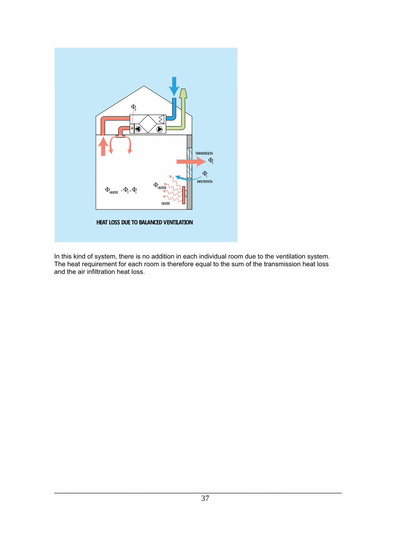
HEAT LOSS DUE TO BALANCED VENTILATION
HEATER
HEATER
HEATER
INFILTRATION
TRANSMISSION
In this kind of system, there is no addition in each individual room due to the ventilation system.The heat requirement for each room is therefore equal to the sum of the transmission heat lossand the air infiltration heat loss.

________________________________________________________________________38
PyroxAddition to/deduction from the heat loss:It is not usual to make any deduction in the calculated power to allow for lighting and other heatsources. This is partly because the building needs to be heated outside normal hours of use, andpartly because it is desirable to incorporate a certain security margin.NS 3032 states the recommended values for power requirements for heating and ventilation in awhole building for various types of building:
Type of building Max. simultaneous power requirement [W/m2] Low Medium High Office building, new 35 40 50 Office building, existing 40 50 60 Nursing home, new 60 70 80 Nursing home, existing 70 80 90 Hotels, new 60 70 80 Hotels, existing 70 80 90 Bathrooms, swimming pools, new 100 140 180 Bathrooms, swimming pools, existing 120 160 200 Detached houses, new, + 20 cm insul. 55 70 85 Detached houses, existing 70 90 110 Blocks of flats, new 40 45 50 Blocks of flats, existing 45 50 60 Schools, new, with gymnasium 40 50 60 Schools, existing, with gymnasium 45 60 70
ExampleYou have been asked to calculate the necessary power requirement to heat a room in a detachedhouse. The house is in Oslo which has a dimensioning outside temperature of -20°C. The desiredroom temperature is 20°C. The room is below an unheated attic (-20°C) and the floor is above abasement (0°C). The house plans provide the following details:
Floor area: 44 m2
Ceiling area: 44 m2
Exterior walls: 29 m2 (less the window area)Window area: 5 m2
Volume of room: 100 m3
The house has a mechanical exhaust ventilation system. The total exhaust air flow rate is 150m3/h. The exhaust air flow rate from the room in question is 50 m3/h. It is assumed that thebuilding's construction complies with the statutory requirements in terms of U factor. This givesthe following data:
Exterior wall: 0.30 W/m2⋅KCeiling: 0.20 "Floor: 0.30 "Window: 2.40 "
________________________________________________________________________39
Pyrox
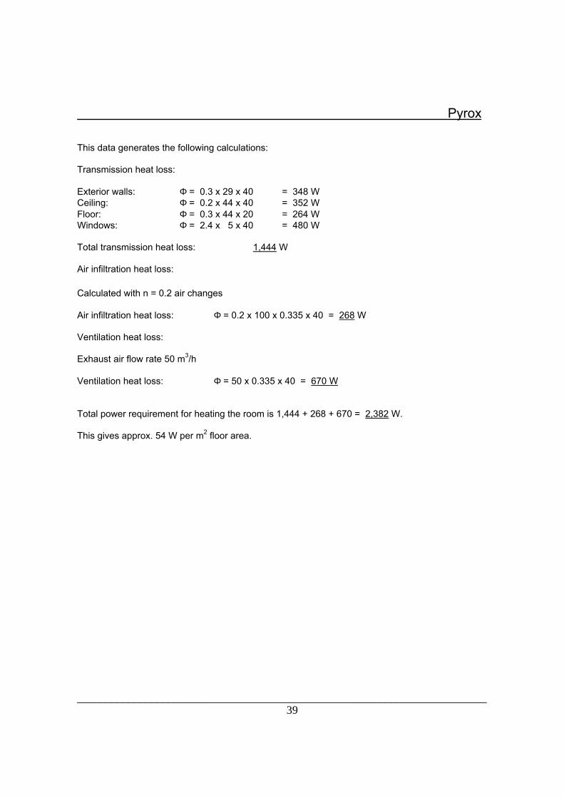
This data generates the following calculations:
Transmission heat loss:
Exterior walls: Φ = 0.3 x 29 x 40 = 348 WCeiling: Φ = 0.2 x 44 x 40 = 352 WFloor: Φ = 0.3 x 44 x 20 = 264 WWindows: Φ = 2.4 x 5 x 40 = 480 W
Total transmission heat loss: 1,444 W
Air infiltration heat loss:
Calculated with n = 0.2 air changes
Air infiltration heat loss: Φ = 0.2 x 100 x 0.335 x 40 = 268 W
Ventilation heat loss:
Exhaust air flow rate 50 m3/h
Ventilation heat loss: Φ = 50 x 0.335 x 40 = 670 W
Total power requirement for heating the room is 1,444 + 268 + 670 = 2,382 W.
This gives approx. 54 W per m2 floor area.
________________________________________________________________________40
12. BUILDINGS' ENERGY REQUIREMENTS Pyrox
GeneralWhen calculating the annual energy requirements of a building for heating rooms and heatingventilation air, we must take the following into account:
_ transmission and air infiltration heat loss_ ventilation heat loss
In the overall calculation we also need to take the building's heat gain into consideration, i.e.:
_ heat from the sun_ heat from electric lighting_ body heat_ heat from machinery and equipment_ heat from fans
This section demonstrates how to calculate the annual energy requirements of a building,including how to take the above-mentioned factors into account:
Definition of central concepts in energy calculations
To be able to carry out an energy calculation, we need to know something about the climaticconditions, and how they vary during the course of the year at the site of the building. Threeconcepts are important to this process:
_ temperature duration curves_ length of the heating season_ number of degree days
The temperature duration curve is plotted by counting the number of days with a meantemperature below a certain temperature. A temperature duration graph can be generated byplotting consecutive values of the temperature and number of days. If this graph is plotted as amean graph covering ten years, it will give an approximately correct picture of the climate for theplace in question. An example of this kind of graph is given below:

________________________________________________________________________41
PyroxTemperature duration graph:
TEMPERATURE DURATION GRAPH
TEMPERATURE DURATIONGRAPH
DAYS
The heating season means the part of the year when the building needs to be heated. The lengthof the heating season is usually calculated as lasting until the mean outside temperature is 10°C.If the temperature duration graph for the location is known, the length of the heating season canbe worked out. The diagram above shows that the length of the heating season will be approx.240 days. The fact that it is generally unnecessary to heat the building outside this period, despitethe outside temperature being lower than room temperature, is due to internal supply of heat andsupplementary heat from the sun.
Degree days means the area which is delimited by the duration graph and an isotherm. The trueterm is degrees multiplied by days, but is usually abbreviated to degree days.
The number of degree days if the desired room temperature is 20°C is shown by the areadelimited by the duration curve and the isotherm 10°C plus the rectangle marked between theisotherms 10 and 20°C as shown in the figure above. For example, if the desired roomtemperature is 17°C, the number of degree days would be the area below the isotherm 10°C plusa rectangle delimited by the isotherms 10 and 17°C.The number of degree days for different places can be found in tables of climatic data or may beobtained on request from the Meteorological Institute.

________________________________________________________________________42
PyroxCalculations of annual energy requirement for heating and ventilationIf the power requirement and the above figures are known, the annual energy requirement can becalculated as follows:
( ) ( ) ( ) [ ]Qt t
Gt t
Gt t
G Q kWhT
R o
I
R o
V
i o
v s t=−
? ? +−
? ? +−
? ? ? −Φ Φ Φ
τ τ τ τ
φT = transmission heat loss (kW)φI = air infiltration heat loss (kW)φV = ventilation heat loss (kW)G = number of degree days (C x days)τ = operative time for heating system, usually 24 hourstR = dimensioning room temperatureto = dimensioning outside temperaturetI = inflowing temperature for the ventilation system, usually the same as tRτv = operative time for the ventilation system, in the case of natural ventilation equal to ττs = takes into account non-operation of ventilation system at weekends. τs = 5/7 in the case of 5 days operation.Qt = heat from the sun, body heat, heat from equipment and other internal sources of heat.
If there is insufficient data to calculate Qt, it may be assumed that this quantity reduces thecalculated energy consumption by approx. 20Ð25%.
NS 3032 states the recommended values for the energy requirement in various types of building:
Type of building Energy requirement (kWh/m2 floor area) Low Medium High
Office building, new 90 110 130 Office building, existing 120 150 180
Nursing home, new 190 220 250
Nursing home, existing 220 270 300 Hotels, new 210 240 270 Hotels, existing 240 280 320 Bathrooms, swimming pools, new 300 500 700 Bathrooms, swimming pools, existing 500 700 900 Detached houses, new, + 20 cm insul. 100 130 170 Detached houses, existing 150 190 240 Blocks of flats, new 100 120 150 Blocks of flats, existing 150 180 220 Schools, new, with gymnasium 100 120 140 Schools, existing, with gymnasium 100 140 180

________________________________________________________________________43
13. RADIANT HEAT Pyrox
Heat transferTransfer of heat always occurs from a higher temperature to a lower temperature. There are fivebasic methods by which this transfer can take place:
_ conduction_ convection_ radiation_ mass transfer_ phase change
Conduction occurs when heat spreads during constant lowering of temperature from a hotter partof a body to a colder part of the same body. Heat can also be conducted from one body toanother if there is close contact between the two.
Convection occurs when heat from a liquid or a gas is conducted to a solid body (or vice versa).
Radiation occurs when heat is transferred from one body to another without heating the mediumpresent between the two bodies, e.g. air. For instance, the sun heats the earth without heatingthe atmosphere between the two.
Mass transfer occurs when the heat content of a fluid alters if it runs through surroundings with adifferent temperature than the fluid itself.
Phase change occurs during evaporation and condensation. In the case of evaporation a certainamount of heat must be applied for phase change to occur, while in the case of condensation acertain amount of heat is released.
In practice, the heating elements used to heat rooms will transfer heat using a combination ofconvection and radiation, depending on the surface temperature of the heating element.
In water-filled radiator systems convection will account for 70Ð80% of the heat output, while therest of the heating occurs through radiation. In radiant heaters, the ratio will be reversed, i.e.radiation will account for more than 80% of the heat transfer.
GeneralIn actual fact, radiant heat consists of electromagnetic rays like radio waves and visible light rays.Heat radiation may or may not occur, depending on the wavelength of the electromagnetic rays.Part of the electromagnetic spectrum is represented below, showing where temperature radiationwill take place:

________________________________________________________________________44
PyroxThe electromagnetic spectrum:
UV radiation Visible light
Temperature radiation (infrared heat)
Microwaves Radio waves
1 nm 1 µm 1 mm 1 m
Radiant heating elements are divided into groups according to how high the elements' surfacetemperature is. One group includes short-wave radiation with temperatures of approx. 750°C, andlong-wave radiant heaters with a surface temperature of approx. 100°C are used in rooms withlow ceilings. In the middle is a group with temperatures of approx. 300°C, used for ceiling heightsof 2.5 to 20 m.
Heating with radiant heat can have many advantages over other types of heating. The radiatedheat passes unimpeded through the air and does not emit heat until it meets surfaces such asfloors and walls. These surfaces in turn emit convection heat to the air in the room, therebyheating the entire living/working area. As such, it is possible to avoid heat collecting under theceiling. Some of the radiated heat will also be absorbed directly by the people in the room.
This effect makes it possible to tolerate an air temperature 2Ð3°C lower than with convectionheating, while experiencing the same degree of comfort.
These factors mean that correctly dimensioned radiant heating is energy-saving.
DefinitionsIn connection with planning of radiant heating and the use of catalogue data, it is important todefine what is meant by a number of concepts and quantities. We shall therefore offer definitionsof the following:
_ heat radiation_ intensity of radiation_ radiation temperature contribution/asymmetry of radiation_ radiation temperature_ air temperature_ operative temperature_ thermal gradient
Heat radiation from a radiant heating panel increases to the power of 4 of the absolutetemperature. This means that the radiant heating panels can be manufactured in very small sizes,while still being capable of emitting considerable heat. The radiated heat emitted from a hotsurface can be calculated using the following equation:
( ) [ ]P A T T Ws s o= ? ?σ ε 4 4_
A = surface area of the radiant heating panel, m2
Ts = absolute temperature of the radiant heating panel, KTo = absolute temperature of the surroundings, Kε = emissivity constantσ = Stefan-Boltzmann's constant = 5.7 x 10⁻⁸ W/m2K4
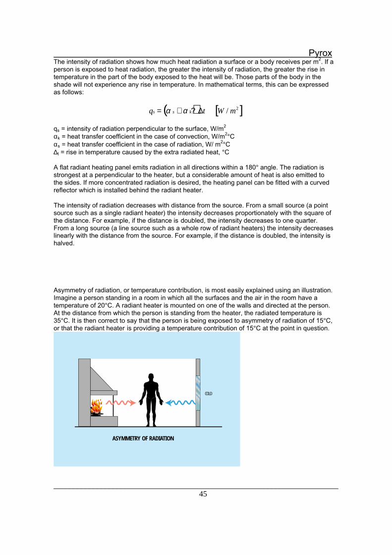
________________________________________________________________________45
PyroxThe intensity of radiation shows how much heat radiation a surface or a body receives per m2. If aperson is exposed to heat radiation, the greater the intensity of radiation, the greater the rise intemperature in the part of the body exposed to the heat will be. Those parts of the body in theshade will not experience any rise in temperature. In mathematical terms, this can be expressedas follows:
( ) [ ]q t W ms s k= + ?α α ∆ / 2
qs = intensity of radiation perpendicular to the surface, W/m2
αk = heat transfer coefficient in the case of convection, W/m2°Cαs = heat transfer coefficient in the case of radiation, W/ m2°C∆t = rise in temperature caused by the extra radiated heat, °C
A flat radiant heating panel emits radiation in all directions within a 180° angle. The radiation isstrongest at a perpendicular to the heater, but a considerable amount of heat is also emitted tothe sides. If more concentrated radiation is desired, the heating panel can be fitted with a curvedreflector which is installed behind the radiant heater.
The intensity of radiation decreases with distance from the source. From a small source (a pointsource such as a single radiant heater) the intensity decreases proportionately with the square ofthe distance. For example, if the distance is doubled, the intensity decreases to one quarter.From a long source (a line source such as a whole row of radiant heaters) the intensity decreaseslinearly with the distance from the source. For example, if the distance is doubled, the intensity ishalved.
Asymmetry of radiation, or temperature contribution, is most easily explained using an illustration.Imagine a person standing in a room in which all the surfaces and the air in the room have atemperature of 20°C. A radiant heater is mounted on one of the walls and directed at the person.At the distance from which the person is standing from the heater, the radiated temperature is35°C. It is then correct to say that the person is being exposed to asymmetry of radiation of 15°C,or that the radiant heater is providing a temperature contribution of 15°C at the point in question.
ASYMMETRY OF RADIATION
COLD

________________________________________________________________________46
PyroxAcceptable asymmetries of radiation are discussed in the ASHRAE Applications Handbook for1995, taking comfort requirements into account. This handbook concludes that asymmetry ofradiation of 12°C will not cause problems for people in normal working clothes. It is recommendedthat the maximum limit is set at 15°C. The table below shows the correlation between asymmetryof radiation and the recommended input radiation heat per m2 of floor area. Other studies showthat people accept varying levels of asymmetry depending on the cause of the asymmetry. It hasbeen demonstrated that most people's threshold is lowest for asymmetry of radiation caused byheat from the ceiling. ISO 7730 contains a recommended maximum limit of 5°C for asymmetrybelow a warm ceiling. On the basis of this recommendation, we suggest that, depending on thetype of building, an interval of 5Ð10°C be adopted for radiant heat installations.
Max. input radiated heat (W/m2) Asymmetry of radiation (oC) 25 3 40 5 80 10 120 15 200 25
This means that if the asymmetry of radiation is not to exceed 10°C, the maximum input radiatedheat can be 80 W/m2 floor area.
The air temperature is quite simply the temperature of the air, unaffected by the radiationtemperature.
The operative temperature is the temperature which a person feels, and is the combined effect ofthe air temperature and the radiated temperature. In practice, the operative temperature is givenby the following equation:
tt t
tt
opl s
ls
=+
= +2 2
∆
top = operative temperaturetl = air temperaturets = radiated temperature∆ts = radiation temperature contribution
It is precisely this factor which is the key to saving energy when using radiation heating.As the equation shows, it is possible to lower the air temperature while still maintainingthe desired operative temperature, thanks to the effect of the radiation temperature. As arule of thumb, it is fair to say that lowering the air temperature by 1°C leads to a 5%reduction in the energy consumption for heating.

________________________________________________________________________47
PyroxFurther energy savings can be made since radiation heating produces a minor vertical thermalgradient, i.e. the difference in temperature between floor and ceiling. In very high-ceilinged roomsin which convectional heating systems often encounter problems with the heat collecting justbelow the ceiling where it fulfils no useful purpose, radiated heat will pass unimpeded through theair and emit warmth where it is needed, thus creating a small vertical thermal gradient.
THERMAL GRADIENT
CEILING HEIGHT
THERMALGRADIENTDUE TORADIANTHEATING
THERMAL GRADIENTDUE TO FAN HEATERS
Planning Ð dimensioning the heating system for a factory or office buildingImagine that you are planing a heating system for a factory or office building, in which theworkstations are spread around the entire premises. The working area must therefore be definedas the entire floor area and up to a height of 2 m above the floor. An operative temperature of18°C is required, which applies 1 m above the floor at the various workstations. Between theworkstations a lower temperature is permissible. In the working area a maximum vertical thermalgradient of 5°C is allowed, since it is a relatively rough environment.
The following data apply to the building:
Length: 40 mBreadth: 20 mCeiling height: 4.0 mWindow area: 80 m2
Entrances/doors: 30 m2

________________________________________________________________________48
FACTORY
The building is located in Oslo which has a dimensioning outside temperature of-20°C. The building's construction is dimensioned in accordance with the statutory requirementsto U factor.
The building has a mechanically balanced ventilation system with diffuse ventilation.
Choice of system
In this case it would be wise to choose radiation heating, which is particularly advantageous incombination with diffuse ventilation. Other types of heating in this case could easily lead to alarge vertical thermal gradient Ð i.e. the heat would collect just below the ceiling where it is of nouse.
A good choice in this case would be HeatLine ceiling-mounted radiant heaters, which are verysuitable for ceiling heights in the 3Ð20 m range.

________________________________________________________________________49
PyroxMaximum requirements for asymmetry of radiation
To verify this, we must check the radiation temperature tables for the product in question. Thetables below show the radiation temperatures for HeatLine radiant heaters with the radiationtemperature contribution at various distances from the heater. This check will be the determiningfactor in deciding the permissible output power per heater.
HLÐ12 0 m 1 m 2 m 3 m HLÐ12 0 m 1 m 2 m 3 m
1 m 17.2 8.9 2.9 0.6 2 m 9.5 6.1 2.8 1.0 3 m 5.8 2.9 1.0 0.8 4 m 2.5 1.7 0.8 0.6
HLÐ17 0 m 1 m 2 m 3 m 1 m 23.2 11.4 3.2 0.8 2 m 10.8 7.2 3.0 1.6 3 m 6.8 3.8 1.6 1.0 4 m 3.1 2.1 1.2 0.8
We set the maximum permitted asymmetry of radiation (temperature contribution) at 10°C sincethis is assumed to be a building in which people are constantly in motion and have modestcomfort requirements. The most critical point will be directly below each heater in the upper partof the working area (2 m directly below the heater).
HLÐ17: From the table we see that at a distance of 1 m from the heater, thetemperature contribution directly below the heater is stated as being 23.3°C. At adistance of 2 m, the contribution drops to 10.8°C. This is still in excess of ourrequirement for 10°C.
HLÐ12: The corresponding figures for this heater are 17.2°C and 9.5°C,respectively. This is below our requirement and the HLÐ12 is therefore a goodchoice in terms of asymmetry of radiation.
Controlling the operative temperature
The operative temperature requirement in the working area was 18°C on average. A maximumvertical thermal gradient of 5°C in the working area is permissible. To check this, we need tocheck how the temperature contribution from the heater decreases as the distance from theheater increases vertically and horizontally. This is important in determining the distance we canallow between the heaters and what air temperature is permissible.

________________________________________________________________________50
Pyrox
The least favourable situation would be with heaters placed at regular intervals of 6Êm, since atthis distance there would be no overlapping of the temperature contribution curves from theheaters. The temperature contribution 2 m below the heater would therefore vary between 9.5and 1.0°C. The correlation between the operative temperature, the air temperature and theradiation temperature contribution is given by the equation:
t tt
op ls
= +∆2
Test with an air temperature of 15°C:
2.0 m directly below the heater : top = 15 + 9.5/2 = 19.75°C2.0 m below, 3.0 m to the side : top = 15 + 1.0/2 = 15.50°C4.0 m directly below the heater : top = 15 + 2.5/2 = 16.25°C4.0 m below, 3.0 m to the side top = 15 + 0.6/2 = 15.30°C
With heaters placed at 6 m intervals, the temperature in the working area would vary between15.3°C and 19.75°C. The least favourable vertical thermal gradient would be 4.45°C, meaningthat the vertical thermal gradient requirement would be fulfilled. By placing the heaters directlyabove the workstations, we see that we would be satisfying the requirement of 18°C at a height of1 m above the floor. It would therefore seem sensible to use HLÐ12 ceiling-mounted heaters inthis case.
Calculation of power requirementThe above calculations showed that with radiant heat we can reduce the air temperature, therebyachieving significant energy savings compared to other heating systems. In this case, it wassufficient to heat the air temperature to 15°C.
Transmission heat loss:
Part of building Area (1) U factor (2) ∆toutside - inside (3) Output(1⋅2⋅3 )Exterior wall (net)Ceiling areaFloor (on ground)Windows Entrances
280 m2
800 m2
800 m2
80 m2
30 m2
0.3 W/m2 oC 0.3 " 0.2 " 2.8 " 2.0 "
35 35 35 35 35
2,940 W 8,400 W 5,600 W 7,840 W 2,100 W
Total: 26,880 W
Air infiltration heat loss:
Let us assume that the building has the value n = 0.2 air changes per hour.
Qinf. = n x Cp ⋅ V x (tr - to) = 0.2 x 0.335 x 2880 x 35 = 6,566 W
Total heat loss: 26880 + 6566 = 33446 ≈ 33.4 kW
PyroxInstallation

________________________________________________________________________51
To cover the combined output requirement, we need to install 28 HLÐ12 heaters each with anoutput power of 1,200 Watt. The following positioning is recommended:
This means that there will be approx. 5 m between the heaters, which more than satisfies ourrequirement for no more than 6 m between the heaters. Variation in the operative temperatureand the thermal gradient will therefore be somewhat less than the above calculations.
Zone heating
There are often many different temperature requirements in the same premises, due to differentworking operations. With radiation heating it is possible to divide the premises into differenttemperature zones as well as providing the opportunity for spot heating of especially exposedworkstations.
The air temperature can be kept low throughout the whole premises, at the same time as raisingthe operative temperature in individual zones to the desired level by installing radiant heatingpanels to suit requirements in each zone.
In this way the heating costs for the building as a whole are kept down, whilst ensuring thenecessary level of comfort in terms of heating.

________________________________________________________________________52
ZONE HEATING

________________________________________________________________________53
14. AIR CURTAINS Pyrox
GeneralOpen doors and entrances represent a huge loss of energy, in addition to creating problems withdraughts. Installing an air curtain can reduce the energy loss and improve the level of comfort.
Three factors contribute to the size of the air stream passing through an open door:
_ difference between outside and indoor pressure_ difference between outside and indoor temperature_ wind velocity against the opening
AIR STREAM PASSING THROUGH AN OPEN DOOR
The difference between outside and indoor pressure can be eliminated using balancedventilation.
Air stream due to differences in temperatureHot air is less dense than cold air. This means that cold outside air will penetrate through theentrance at the lower part of the opening, pressing warm indoor air out through the top of theopening. This exchange of air is caused by thermal currents, and is due to the fact that themasses of cold air and warm air have different densities. The air stream through the entrance canbe calculated using the following equation:
LB
H gtm
=3
1 50
, µρ
ρ∆
where:
B = width of the entrance [ m]H = height of the entrance [ m]µ0 = flow coefficient (0.8Ð0.9)g = coefficient of gravity (9.81 m/s2)∆ρ = the difference in density between the masses of airρm = the average density of the masses of air

________________________________________________________________________54
Pyrox
Air stream due to effect of wind:The air stream through the entrance is reinforced by the effect of the wind. Let us assume that thewind will make the air stream uniform across the entire opening. After a while the premises willhave such a large overpressure that the air stream is limited to what leaks out through gaps in thebuilding. The air stream due to the effect of the wind is calculated using the following equation:
L B Hv
v = 10
20 25,
where:
v10 = the wind's mean annual velocity at a height of 10 m0.25 = the wind direction's frequency factorB = the width of the entrance [m]H = the height of the entrance [m]
Example Ð calculating annual loss of energy through an entrance
Width of entrance: 4 mHeight of entrance: 5 mTime entrance is open: 1 hour/24 hours, 5 days a week (5 min each time)Mean annual outside temperature: 6.5°CIndoor temperature: 18°CMean annual wind velocity v10 = 4 m/sPrice of energy: NOK 0.50/kWh
Air penetration due to thermal currents
Lt = 4/3 x 51,5 x 1.0 x 9 810 06 1 24, , / ,?
= 10.26 m3/s
Air penetration due to wind
Lv = 4 x 5 x 4/2 ⋅ 0.25 = 10 m3/s
Total air penetration: ≈ 20 m3/s
This represents an energy loss over the course of one year of:
Eloss = 20 x 1.24 x (18 - 6.5) x 1 x 260 = 74,152 kWh
On the basis of the above energy price, this results in an energy cost ofNOKÊ37,000 per year.
Installing air curtains
An air curtain creates an effective barrier in the entrance, preventing the penetration of coldoutdoor air. The air velocity from the air curtain must be so great that the resulting air velocity isdirected downwards. The air curtain should be set so that a small part of the air stream is directedout of the opening, while the rest blows into the premises. In this way, the cold outside air isborne out again with the barrier, while the warm indoor air is kept inside.

________________________________________________________________________55
Pyrox
Installation
To achieve the best possible result, the air door units should be positioned as close to theopening as possible, and they should extend over the entire width of the entrance.
INSTALLATION OF AIR CURTAINS
air curtains
Energy-saving potential
The energy-saving potential depends on the height of the entrance. Measurements show thatwhen used in entrances up to 3.5 m high, air curtains reduce energy loss by 90%. For entranceshigher than 3.5 m, the savings decrease approximately linearly in proportion to the height of theentrance. For entrances which are 7 m high, the energy-saving potential is down to approx. 30%.

________________________________________________________________________56
PyroxThe following graph shows the correlation:
Normal energy saving with air door
0
10
20
30
40
50
60
70
80
90
100
1 2 3 4 5 6 7 8 9 10 11
Hight (m)
Saving (%)
In the above example with an entrance 5 m high, we see from the graph that it is possible toreduce energy loss by approx. 75% by installing air curtains.

________________________________________________________________________57
15. FAN HEATERS Pyrox
GeneralFan heaters are particularly suitable for heating industrial buildings and warehouses where rapid,practical and economical heating of the premises is required. The installation costs for fanheaters are lower per kW input than for MANY other heating systems.
To a achieve a good result, it is vital that the hot air jet reaches right down to the floor. Thismeans that this type of heating is not suitable for combination with diffuse ventilation or othersystems which are sensitive to air velocities in the working area.
The fan heaters can be fitted with a mixing unit for combining indoor and outside air so that thefans also cater for the premises' need for ventilation.
Planning and installationAs described above, to achieve a satisfactory result it is essential that the jet of warm air reachesright down to the floor. This means that we must calculate the maximum height at which the fanscan be mounted while still allowing the air jet to reach the floor. The jetÕs downthrust depthdepends on:
_ the difference in temperature between incoming air and air in the room_ the incoming velocity and dimensions of the outflow outlet_ the angle at which the jet of air is directed towards the floor
For a given angle, the jetÕs downthrust depth can be expressed as follows:
z k lz= ? where:
kz = the downthrust factor shown in the figure belowl = the square root of the outflow areaz = the centreline of the air jetÕs downthrust depth

________________________________________________________________________58
Pyrox
The Archimedes figure expresses the relationship between the upthrust forces and the massforces in a jet of air. We define this figure as follows:
Art g l
T u=
∆
02
where:
g = the acceleration of gravity = 9.81 m/s2
∆t = the difference in temperature between the outflow air and the air inside the roomT = the absolute temperature in the outflow airuo = the outflow velocity [m]
The air jetÕs downthrust depth can then be discovered by:
_ finding the Archimedes figure for the jet of air_ reading the constant kz
_ finding the length of z= kz x l
Example of calculation
We shall calculate how high up the wall the fan in the diagram below can be mounted:
The fan heaters are to be mounted on the wall and set diagonally at an angle of 45° pointingdownwards in premises with the following specifications:
Room temperature: 10°CDimensions of the outflow opening. 0.5 x 0.5 mOutflow velocity: 5 m/sOutput: P = 45 kW

________________________________________________________________________59
MAXIMUM MOUNTING HEIGHT OF FAN HEATERS
Calculations
Volume of air: L = u0 x A = 5 x 0.25 = 1.25 m3/sRise in temperature: ∆t = P/ (L ρ cp) = 30°CArchimedes figure: Ar = 0.0196Downthrust factor: Kz = 6
The downthrust depth z of the jet's centreline. approx. 3 m
The lowest point of the jet will then be clear, providing that we know the breadth of the jet, whichis expressed as b = s x 0.22, where s equals the distance along the centreline to the lowest pointof the jet. This distance will be approximately equal to z/sin 45° = 4.2 m.
It therefore follows that the breadth of the jet (the distance from the centreline to the outer edge)is approximately 0.9 m.
Our conclusion must therefore be that the lowest point in the jet will be approximately 4Êm belowthe fan. This means that, in this case, the fans should not be mounted any higher up the wall thanapprox. 4 m.

________________________________________________________________________60
16. CONVECTION HEATERS Pyrox
GeneralHeating rooms using radiators is based on the principle of heat being transferred convectionallyfrom the heated surface of the radiator to the air inside the room. The circulation of air above theradiator is due to thermal currents causing a rising stream of warm air from the radiator. Theradiators are usually installed beneath windows to eliminate cold draughts from these. Theprimary heating effect (70Ð80%) is caused by convection, while the rest is caused by radiation.
In rooms with normal ceiling heights this heating principle will produce an even temperaturethroughout the entire room. In rooms with very high ceilings, however, there is some danger ofthe heat collecting just below the ceiling. This problem can be countered by installing fans on theceiling which cause the air to circulate, thus evening out the temperature in the room .
Calculation of power requirementRadiators are selected on the basis of a calculation of the power requirement for the premises.The principle of this process has already been outlined. It must be taken into account thatoverhanging windowsills reduce the emission of heat by 2Ð5%, while casing which allows the airto circulate gives a reduction of 15% since the emission of radiated heat is reduced.
Water-filled radiatorsRadiators are selected from catalogues which normally state the output at a difference intemperature of 60°C between the mean radiator temperature and the room temperature. This isbased on the ingoing and outgoing temperatures of90Ð70°C, giving a mean temperature of 80°C. If you deduct a room temperature of 20°C theresult is 60K. It is interesting to see what the output of the radiator is when the difference intemperature over the radiator is different to that on which the catalogue data is based.Measurements show that with a temperature difference deviating from ∆T = 60°C, the new outputΦ = can be shown by the following equation:
ΦΦ
∆kat
t=
↵√60
1 33,
Example
The radiators in an old building with a water-filled heating system are dimensioned for flow/returntemperatures of 90/70°C. In connection with the installation of a heating pump, the heatingsystem is adjusted to a low temperature system with flow/return temperatures of 55/45°C.
The catalogue data has been consulted to provide information about the existing radiators, whichare claimed to have an output 2000 W each. What will the new output figure for these radiatorsbe with the new flow/return temperatures stated above?
Φ = Φkat ⋅ (∆t/60)1,33 = 2000 x [ [(55+45)/2-20]/60]1.33 = 795 Watt
This shows us that the output is more than halved by reducing the flow temperature to 55°C.

________________________________________________________________________61
17. REGULATING TEMPERATURE Pyrox
ThermostatsOn/off thermostats
The simplest and cheapest method of maintaining an even temperature in a heated room is touse a thermostat which is sensitive to room temperature and switches the heat source on or offas necessary.
An important concept when discussing thermostatic control is the switching resolution. Athermostat which turns itself off at 24°C and on at 25°C has a switching resolution of 1°C.
It is best to have a small switching resolution, since this reduces fluctuations in room temperatureso that it remains as stable as possible. There are many types of thermostat. In general, it ispossible to distinguish between mechanical thermostats, such as capillary tube thermostats, andelectronic thermostats.
Electronic thermostats are somewhat more expensive than mechanical ones, but they have theadvantage of having adjustable switching resolutions and extremely precise settings. Theswitching resolution must not be made too small when controlling heating via contactors sincethey may turn themselves on and off at very short intervals, causing a great deal of wear andmore noise.
Multistage thermostats
In systems with a large output it is better not to turn the whole power plant on and off. In this kindof system it is usual to divide the output among two or more component parts and switch in asmuch power as necessary.
This kind of temperature control leads to less wear on the network when large outputs are to becontrolled, as well as resulting in more even temperatures.
Pre-programmed controlWith larger outputs, it is possible to use pre-programmed control. For instance, a channel batterycan be divided into a number of groups. If Group 1 is set at 1 kW, Group 2 is set at 2 kW whileGroup 3 is at 4 kW. Various combinations of these three output groups allow 7-stage outputcontrol.
Infinitely variable temperature controlTemperature control of the type Pulser or TTC is often used as an alternative to output controlwith on/off or 3-stage thermostats. Pulser 220 and TTC use a triac in the control circuit. A triac isa semiconductor which can connect and disconnect the current to electrical heating elementswithout the disturbing noise which can occur with temperature control using contactors.
One whole connection and disconnection cycle takes approx. 1 minute or less. The output isincreased by increasing the on-time and reducing the off-time accordingly. The output regulatorsare also equipped with a temperature regulator and a potentiometer. The temperature sensor canbe built-in or external. Triac regulators cannot be used to control contactors, and therefore cannotbe used to regulate fan heaters or air curtains. However, this type of regulator is extremelysuitable for use with radiant heaters and channel batteries.

________________________________________________________________________62
PyroxTriac and binary switchThe most precise temperature regulation for large outputs is achieved by combining atemperature regulator with a binary switch. The smallest output stage can then be controlledusing triac controls, while the rest of the stages are controlled by a binary switch.

________________________________________________________________________63
18. APPENDIX Pyrox
Documentation for radiant heat
HEATLINE RADIANT HEATERS Ð RADIATION TEMPERATURE CONTRIBUTIONThese tables show the radiation temperature contribution at various distances horizontally andvertically from the midpoint of the heater:
HL 08 0 m 1 m 2 m 3 m1 m 14.8 7.9 2.6 0.42 m 9.5 3.8 2.0 0.53 m 4.8 1.2 0.8 0.44 m 2.5 0.8 0.2 0.1
HL 12 0 m 1 m 2 m 3 m1 m 17.2 8.9 2.9 0.62 m 9.5 6.1 2.8 1.03 m 5.8 2.9 1.0 0.84 m 2.5 1.7 0.8 0.6
HL 17 0 m 1 m 2 m 3 m1 m 23.2 11.4 3.2 0.82 m 9.8 7.2 3.0 1.63 m 6.8 3.8 1.6 1.04 m 3.1 2.1 1.2 0.8
HL 21 0 m 1 m 2 m 3 m1 m 25.6 14.7 4.2 1.22 m 11.3 7.3 3.5 1.73 m 6.9 3.9 1.9 1.34 m 3.2 2.1 1.4 0.9
HL 32 0 m 1 m 2 m 3 m1 m 30.7 26.2 3.9 1.02 m 14.4 9.5 6.7 2.93 m 7.7 6.3 5.8 3.34 m 4.9 3.7 3.1 1.0
HL 42 0 m 1 m 2 m 3 m1 m 35.9 30.7 4.7 1.22 m 16.5 11.3 8.0 3.53 m 9.2 7.6 6.9 3.94 m 5.8 4.4 3.5 1.2
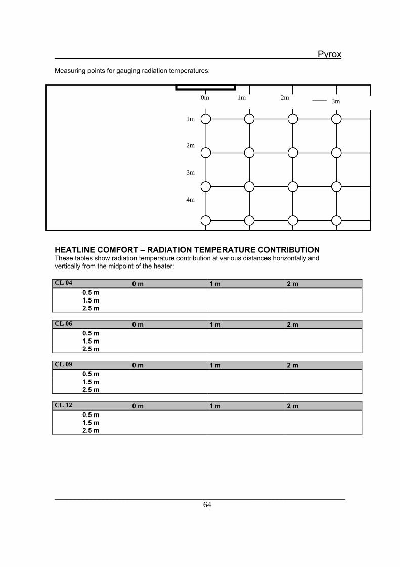
________________________________________________________________________64
Pyrox
Measuring points for gauging radiation temperatures:
s
HEATLINE COMFORT Ð RADIATION TEMPERATURE CONTRIBUTIONThese tables show radiation temperature contribution at various distances horizontally andvertically from the midpoint of the heater:
CL 04 0 m 1 m 2 m0.5 m1.5 m2.5 m
CL 06 0 m 1 m 2 m0.5 m1.5 m2.5 m
CL 09 0 m 1 m 2 m0.5 m1.5 m2.5 m
CL 12 0 m 1 m 2 m0.5 m1.5 m2.5 m
1m
2m
3m
4m
0m 1m 2m _________3m

________________________________________________________________________65
Pyrox
Documentation for air curtains
These tables show air velocities measured at different distances from the outlet opening atmaximum and minimum fan speeds. These values apply to isothermal air supply.
LRX
Distance(m) Air velocity, max. (m/s) Air velocity, min. (m/s)0.5 3.1 1.41.0 2.0 0.51.5 1.7 0.22.0 2.0 -
LG
Distance(m) Air velocity, max. (m/s) Air velocity, min. (m/s)0 7.1 5.5
1.0 5.0 4.02.0 3.5 2.62.5 3.1 2.3
LGW
Distance (m) Air velocity, max. (m/s) Air velocity, min. (m/s)0 5.6 3.81 3.0 2.12 2.0 1.2
2.5 1.9 1.0
MTV
Distance (m) Air velocity, max. (m/s) Air velocity, min. (m/s)1 6.8 -2 6.4 -3 5.5 -4 5.0 -5 4.0 -6 3.5 -