25 str vibrations
TRANSCRIPT
8/14/2019 25 STR VIBRATIONS
http://slidepdf.com/reader/full/25-str-vibrations 1/48
25 Structural vibrations
25.1 Introduction
In this chapter, we will commence with discussing the free vibrations of a beam, which will be
analysed by traditional methods. This fundamental approach will then be extended to forced
vibrations and to damped oscillations, all on beams and by traditional methods.
The main snag with using traditional methods for vibration analysis, however, is that it is
extremely difficult to analyse complex structures by this approach. For this reason, the finite
element method discussed in the previous chapters will be extended to free vibration analysis, andapplications will then be made to a number of simple structures.
Vibrations of structures usually occur due to pulsating or oscillating forces, such as those due
to gusts of wind or from the motion of machinery, vehcles etc. If the pulsating load is oscillating
at the same natural frequency of the structure, the structure can vibrate dangerously (i.e. resonate).
If these vibrations continue for any length of time, the structure can suffer permanent damage.
25.2 Free vibrations of a mass on a beam
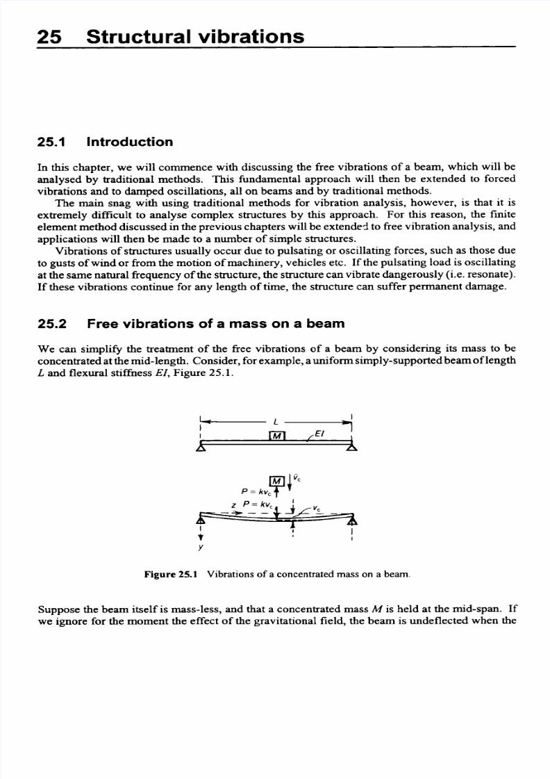
We can simplify the treatment of the free vibrations of a beam by considering its mass to be
concentrated at the mid-length. Consider, for example, a uniform simply-supportedbeam of length
L and flexural stiffnessEZ,Figure 25.1.
Figure 25.1 Vibrations of a concentrated mass on a beam.
Suppose the beam itself is mass-less, and that a concentrated mass M is held at the mid-span. If
we ignore for the moment the effect of the gravitational field, the beam is undeflected when the

8/14/2019 25 STR VIBRATIONS
http://slidepdf.com/reader/full/25-str-vibrations 2/48
644 Structural vibrations
mass is at rest. Now consider the motion of the mass when the beam is deflected laterally to some
position and then released. Suppose, v, is the lateral deflection of the beam at the mid-span at a
time t ; as the beam is mass-less the forceP on the beam at the mid-span is
48 Elv,p =-3
If k = 48 EI/L’, then
P = kv,
The mass-less beam behaves then as a simple elastic springc.fstiffnessk. In the deflected position
there is an equal and opposite reactionP on the mass. The equation of vertical motion of the massis
Thus
The general solution of this differential equation is
v, = Ac os Et + Bsin E
where A and B are arbitrary constants;this may also be written in the form
where C and E are also arbitrary constants. Obviously C is the amplitude of a simple-harmonic
motion of the beam (Figure 25.2); v, first assumes its peak value when

8/14/2019 25 STR VIBRATIONS
http://slidepdf.com/reader/full/25-str-vibrations 3/48
Free vibrations of a mass on a beam 645
Figure 25.2 Variations of displacement of beam with time.
and again attains h s alue when
@ + . = -x
K
2
Thls period T of one complete oscillation is then
T = t l - t z = 2 ~ (25.1)
The number of complete oscillations occurring in unit time is the frequency of vibrations; this is
denoted by n,and is given by
n = - = - - (25.2)T 2nT
The behaviour of the system is therefore directly analogous to that of a simple mass-spring system.
On substituting for the value of k we have
(25.3)= - = - -2nlcL
Problem 25.1 A steel I-beam, simply supported at each end of a span of 10 m, has a second
momentof area of l O - 4 m4. It carries a concentrated mass of 500kg at the mid-
span. Estimate the natural frequency of lateral vibrations.
8/14/2019 25 STR VIBRATIONS
http://slidepdf.com/reader/full/25-str-vibrations 4/48
646 Structural vibrations
Solution
In this case
EI = (200 x 109)(10-4)= 20 x lo6 Nm2
Then
k = - -8E' - 48(20 x lo6) = 960 x 103 N/m
L 3 ( 1o ) ~
The natural frequency is
n = - F 1 = 6.97 cyclestsec = 6.97 Hz2x M 2x 500
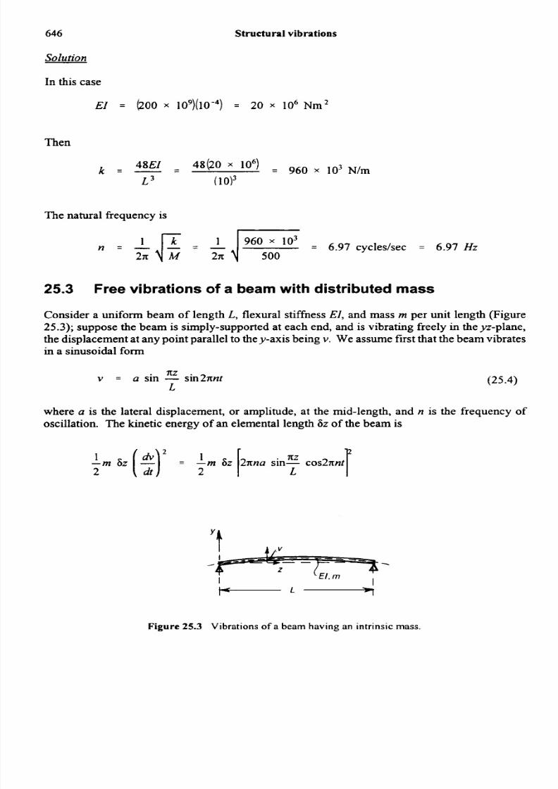
25.3 Free vibrations of a beam with distributed mass
Consider a uniform beam of length L, flexural stiffnessEI, and mass m per unit length (Figure25.3); suppose the beam is simply-supported at each end, and is vibrating freely in the yz-plane,the displacement at any point parallel to the y-axis being v. We assume first that the beam vibrates
in a sinusoidal form
Nv = a sin - in2xnt (25.4)
L
where a is the lateral displacement, or amplitude, at the mid-length, and n is the frequency of
oscillation. The kinetic energy of an elemental length 6z of the beam is
Pm 6 z (2) 2 I L
2XZ
= - m 6z 2xna sin- cos2xnt
Figure 25.3 Vibrations of a beam having an intrinsic mass.

8/14/2019 25 STR VIBRATIONS
http://slidepdf.com/reader/full/25-str-vibrations 5/48
Free vibrationsof a beam with distributed mass
The bending strain energy in an elemental length is
sin - in2nnt 6z
1
- E I [ s ) ijz = - EI 1- an2w
2 2 L 2 L
The total kinetic energy at any time t is then
cos2 2nnt I' in2 .E2 L
The total strain energy at time t is
sin22nnt kL in2 E d~
a 2 d-EI -2 L 4 L
641
(25.5)
(25.6)
For the free vibrations we must have the total energy, i.e. the s u m of the kinetic and strain energies,
is constant and independent of time. This is true if
-m (4n2n2a2)os2 2nnt + -EI [-2 sin2 2nnt = constant2 2
For h s ondtion we must have
--m (47r2n2a2)= T E I [ ,n 4 a 2
2
This gives
Now mL = M , say is the total mass of the beam, so that
= n\lKM L 3
(25.7)
( 2 5 . 8 )
This is the frequency of oscillation of a simply-supported beam in a single sinusoidal half-wave.
If we consider the possibility of oscillations in the form
2 w .v = a s i n - SUI2nn2t
L

8/14/2019 25 STR VIBRATIONS
http://slidepdf.com/reader/full/25-str-vibrations 6/48
648 Structural vibrations
then proceeding by the same analysis we find that
n, = 4n , = 21cJZ (25.9)
" h s is the frequency of oscillations of two sinusoidal half-waves along the length of the beam,Figure 25.4, and corresponds to the second mode of vibration. Other higher modes are found
similarly.
Figure 25.4 Modes of vibration of a simply-supportedbeam.
As in the case of the beam with a concentrated mass at the mid-length, we have ignoredgravitation effects; when the weight of the beam causes initial deflections of the beam, oscillationstake place about this deflected condition; otherwise the effects of gravity may be ignored.
The effect of distributing the mass uniformly along a beam, compared with the whole mass
being concentrated at the mid-length, is to increase the frequency of oscillations from
q-GE to ; j - EL 3
n, =
Liz,n
and n2 = 24%
2X M L 3
If
then

8/14/2019 25 STR VIBRATIONS
http://slidepdf.com/reader/full/25-str-vibrations 7/48
Forced vibrations of a beam carrying a single mass 649
(25.10)
Problem 25.2 If the steel beam of the Problem 25.1 has a mass of 15 kg per metre run,estimate the lowest natural frequency of vibrations of the beam itself.
Solution
The lowest natural frequency of vibrations is
Now
EI = 20 x lo6Nm2
and
ML3 = (15) (10) = 150 x lo 3kg.m3
Then
= 133 s - ’I - 20 x lo6
ML3 150 x lo3- -
Thus
n1 = 5 = 18.1 cycles per sec = 18.1 Hz2
25.4 Forced vibrations of a beam carrying a single mass
Consider a light beam, simply-supported at each end and carrying a massM at mid-span, Figure25.5. Suppose the mass is acted upon by an alternating lateral force
P sin 2lcNt (25.11)
which is applied with a frequencyN. If v, is the central deflection of the beam, then the equationof motion of the mass is

8/14/2019 25 STR VIBRATIONS
http://slidepdf.com/reader/full/25-str-vibrations 8/48
650 Structural vibrations
d2vc
dt 2
M- + kv, = P sin 2nNt
where k = 48 EI/L'. Then
PvC = - in 2nNt
2Vc k- + -
d t 2 M M
Figure 25.5 Alternating force applied to a beam.
The general solution is
P-sin2nNt
(25.12)VC = R c o s E t + B s i n E t + 1k4n2N2-
k
in which A and B are arbitrary constants. Suppose initially, i.e. at time t = 0, both v, and dvydt
are zero. Then A = 0 and
P2nN.-
k 1B = -
1 - 4n'N' f
EThen

8/14/2019 25 STR VIBRATIONS
http://slidepdf.com/reader/full/25-str-vibrations 9/48
Forced vibrations of a beam carrying a single mass
v, =M
1- 4n2N2-k
Now, the natural frequency of free vibrations of the system is
n = LE2n
Then
FM2nn
and
nv, =
1 - N21n2
Now, the maximum value that the term
n
may assume is
and occurs when sin 2nNt = -sin 2nnt = 1 . Then
- Plk- -
Plk ( I + !1 - -
N1 - -2
vcmax =
n 2 n
65 1
(2 5 . 1 3 )
(2 5 . 1 4 )
(2 5 . 1 5 )
Thus, if N < n, v is positive and in phase with the alternating loadP sin 2nNt. As N approaches
n, he values of v,,, become very large. When N > n, v,,, is negative and out of phase with P
sin 27tNt. When N =n , the beam is in a condition of resonance.

8/14/2019 25 STR VIBRATIONS
http://slidepdf.com/reader/full/25-str-vibrations 10/48
652 Structural vibrations
25.5 Damped free oscillations of a beam
The free oscillations of practical systems are idnbited by damping forces. One of the commonest
forms of damping is known as velocity, or viscous, damping; the damping force on a particle or
mass is proportional to its velocity.
Figure 25.6 Effect of damping on free vibrations.
Suppose in the beam problem discussed in Section 25.2 we have as the damping force p(dv/dr).
Then the equation of motion of the mass is
M - *vC = - h c - p - C
dt dt
Thus
d 'v, *C
M - + p- + h, = 0dt 2 dt
Hence
d2Vc p *, k
dt2 M dt M- + - - + - v c = 0
The general solution of this equation is
V , = A e { - f l m i w } t B e{ k d m - m f (25.16)

8/14/2019 25 STR VIBRATIONS
http://slidepdf.com/reader/full/25-str-vibrations 11/48
Damped free oscillations of a beam 653
Now (k/M) is usually very much greater than (p/2M)’, and so we may write
= A e ( - @ U &% + Be (-Idm - lm I
v c
-fJdm) b E l m + Be -lm]
(25.17)e
= e - w m ) [ccosh + $1
Thus, when damping is present, the free vibrations given by
ccos[& + e)
are damped out exponentially, Figure 25.7. The peak values on the curve of vc correspond to
points of zero velocity.
Figure 25.7 Form of damped oscillationof a beam.
These are given by
* c - 0. -
dt
or

8/14/2019 25 STR VIBRATIONS
http://slidepdf.com/reader/full/25-str-vibrations 12/48
654 Structural vibrations
Obviously the higher peak values are separated in time by an amount
T = 2 x E
We note that successive peak values are in the ratio
"CI-cz
Then
Now
Thus
- Plog, - -
vc2 2M n
Hence
v cp = 2M n log, -
V c r
(25.18)
(25.19)
(25.20)
(25.21)

8/14/2019 25 STR VIBRATIONS
http://slidepdf.com/reader/full/25-str-vibrations 13/48
Damped forced oscillations of a beam 655
25.6 Damped forced oscillations of a beam
We imagine that the mass on the beam discussed in Section 25.5 is excited by an alternating forceP sin 2nNt. The equation of motion becomes
d2vc h CM - + p- kv, = P sin 2ldvtdt dt
The complementary function is the damped free oscillation; as this decreases rapidly in amplitudewe may assume it to be negligible after a very long period. Then the particular integral is
P sin 2nNt
MDz DD + kvc =
This gives
P [ ( k - 4x2N2M)sin2nNt-2xNp cos2nNtl
If we write
then
v c = P1(1-5)in2nNt-2xNp cos2xNt
The amplitude of this forced oscillation is
Pvmax = r
(25.22)
(25.23)
(25.24)
8/14/2019 25 STR VIBRATIONS
http://slidepdf.com/reader/full/25-str-vibrations 14/48
656 Structural vibra tion s
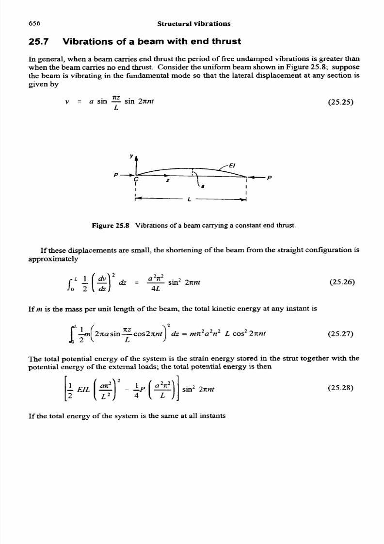
25.7 Vibrations of a beam with end thrust
In general, when a beam carries end thrust the period of free undamped vibrations is greater thanwhen the beam carries no end thrust. Consider the uniform beam shown in Figure 25.8; supposethe beam is vibrating in the fundamental mode so that the lateral displacement at any section is
given by
5cZv = a sin - in 2mt (25.25)
L
Figure 25.8 Vibrations of a beam carrying a constant end thrust.
If these displacements are small, the shortening of the beam from the straight configuration is
approximately
sin2 2nnt (25.26)oL $(Le)’&-2 ~ 2
4L
If rn is the mass per unit length of the beam, the total kinetic energy at any instant is
(25.27)2 2
]I
[ ~ ( 2 n n s i n T c o s 2 ~ n fZ dz = mn a n L cos2 2xnt
The total potential energy of the system is the strain energy stored in the strut together with thepotential energy of the external loads; the total potential energy is then
[f ElL [$ I2 -2(?I]in2 2xnt (25.28)
If the total energy of the system is the same at all instants

8/14/2019 25 STR VIBRATIONS
http://slidepdf.com/reader/full/25-str-vibrations 15/48
Derivation of expression for the mass matrix 657
This gives
where
d E I
L 2
Pe = -
and is the Eu ler load of the column . If we write
then
(25.29)
(25.30)
n = n , 1 - -d :
Clearly, as P approaches P,, the natural frequency of the colum n diminishes and approaches zero.
25.8 Derivation of expression for the mass matrix
Consider an m fiite sim all y small element of volume d(vo1) and density p, oscillating at a certain
time t, with a velocity u.
The km etic energy 01 this element (KE) is given by:
1
2KE = -p x d(v0l) x 2j2
and for the whole body,
K E z - p u 2 d(v0l)2
(25.31)

8/14/2019 25 STR VIBRATIONS
http://slidepdf.com/reader/full/25-str-vibrations 16/48
658 Structuralvibrations
or in matrix form:
(25.32)
NB The premultiplier of equation (25.32) must be a row and the postmultiplier of thisequation must be a colum n, because KE is a scalar.
Assum ing that the structure oscillates with simple harmonic motion, as described in Section 25.2,
{u } = {c}ejw'
where
{C} =
61 = resonant frequency
j = J i
a vector of amplitudes
Differentiating {u } with respec t to t,
{ u } = j o {C} elw'
= j o {u }
Substituting equation (25.35) into equation (25.32):
1 4 ' P { 4 4 v o l )= - - - 2
vol2
but,
(4 = [NI u,}
1
2: KE = -- o2 (u,}' [ NIT [N] (v01) (u,}vol
(25.33)
(25.34)
(25.35)
(25.36)
8/14/2019 25 STR VIBRATIONS
http://slidepdf.com/reader/full/25-str-vibrations 17/48
Ma ss matrix for a rod element
but,
659
or in matrix form:
but,
(I',} = io (11,)
... KE = --a2 (11,}7 [m] (11,)2
Comparing equation (25.37) with equation (25.36):
[m l = 1 [NITP [NI4vol)
vo l
(25.37)
(25.38)
= elemental mass matrix
25.9 Mass matrix for a rod element
The one-dimensional rod element, which has two degreeof freedom, is shown in Figure 23.1. A s
the rod element hastwo degreesof freedom, it will be convenient to assume a polynomial with two
arbitrary constants, as shown in equation (25.39):
u = a, + ap
The boundary conditions or boundary values are:
at x = 0, u = u,
and
at x = I , u = u2
Substituting equations (25.40) into equation (25.39),
al = u ,
(25.39)
(25.40)
(25.41)
8/14/2019 25 STR VIBRATIONS
http://slidepdf.com/reader/full/25-str-vibrations 18/48
66 0 Structuralvibrations
and
u2 = u1 + %I
or
= (u 2 - u1Yl
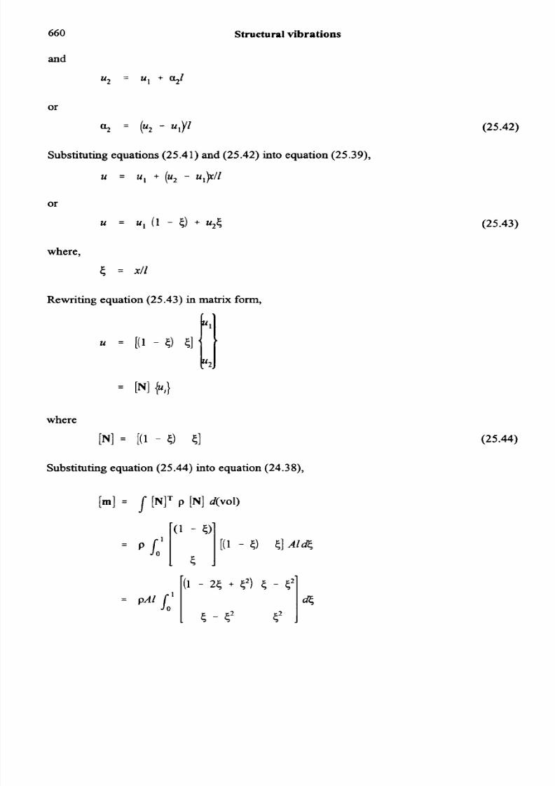
Substituting equations (25.41) and (25.42) into equation (25.39),
u = u , + (u2 - u l p l
where,
5 = XI1
Rewriting equation (25.43)in matrix form,
Substituting equation (25.44) into equation (24.38),
5 1
1 - 2 5 + 5 * ) 5 - 5 :
5 - 5 5
4
(25.42)
(25.43)
(25.44)
8/14/2019 25 STR VIBRATIONS
http://slidepdf.com/reader/full/25-str-vibrations 19/48
Mass matrix for a rod element
[rl =
u1 u2
:cs c
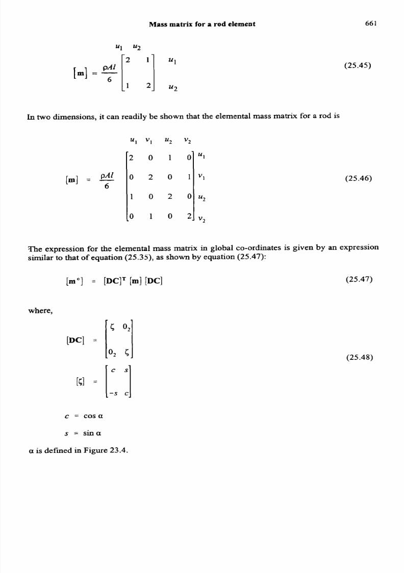
In two dimensions, it can readily be show n that the elemental mass matrix for a rod is
u1 VI u 2 v 2
2 0 1 0
0 2 0 1
1 0 2 0
0 1 0 2
66 1
(25.45)
(25.46)
The expression for the elemental mass matrix in global co-ordinates is given by an expressionsimilar to that of equation (25.35),as shown by equation (25.47):
[mol = [DCIT [m] [DC] (25.47)
where,
c = c o s a
(25.48)
s = sina
a is defined in Figure 23.4.
8/14/2019 25 STR VIBRATIONS
http://slidepdf.com/reader/full/25-str-vibrations 20/48
662 Structural vibrations
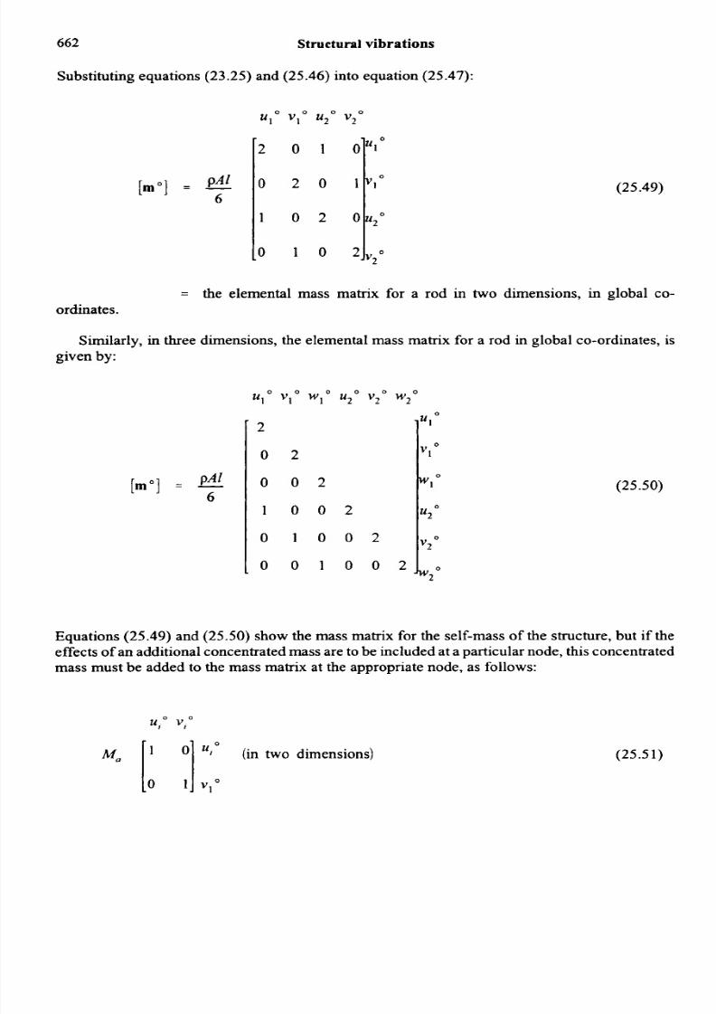
Substituting equations (23.25) and (25.46) into equation (25.47):
(25.49)
= the elemental mass matrix for a rod in two dimensions, in global co-ordinates.
Similarly, in three dimensions, the elemental mass matrix for a rod in global co-ordinates, is
given by:
[mol =
2
0
(25.50)
Equations (25.49) and (25.50) show the mass matrix for the self-mass of the structure, but if the
effects of an additional concentratedmass are to be included at a particular node, this concentrated
mass must be added to the mass matrix at the appropriate node, as follows:
U,O V,O
ML? [ y ](in two dimensions) (25.51)

8/14/2019 25 STR VIBRATIONS
http://slidepdf.com/reader/full/25-str-vibrations 21/48
Ma
Element 1-3
Q = 60°, c = 0.5, s = 0.866
l , . 3 = -m - 1.155 m = length of element 1-3sin 60
-1 0 0 Y o
0 1 0 V I 0
0 0 1- W,O
(in three dimensions) (25.52)
8/14/2019 25 STR VIBRATIONS
http://slidepdf.com/reader/full/25-str-vibrations 22/48
664 Structural vibrations
0.433 x lo7 0.75 x lo7
0.75 x 10⁷ 1.3 x 1 0 ' ~
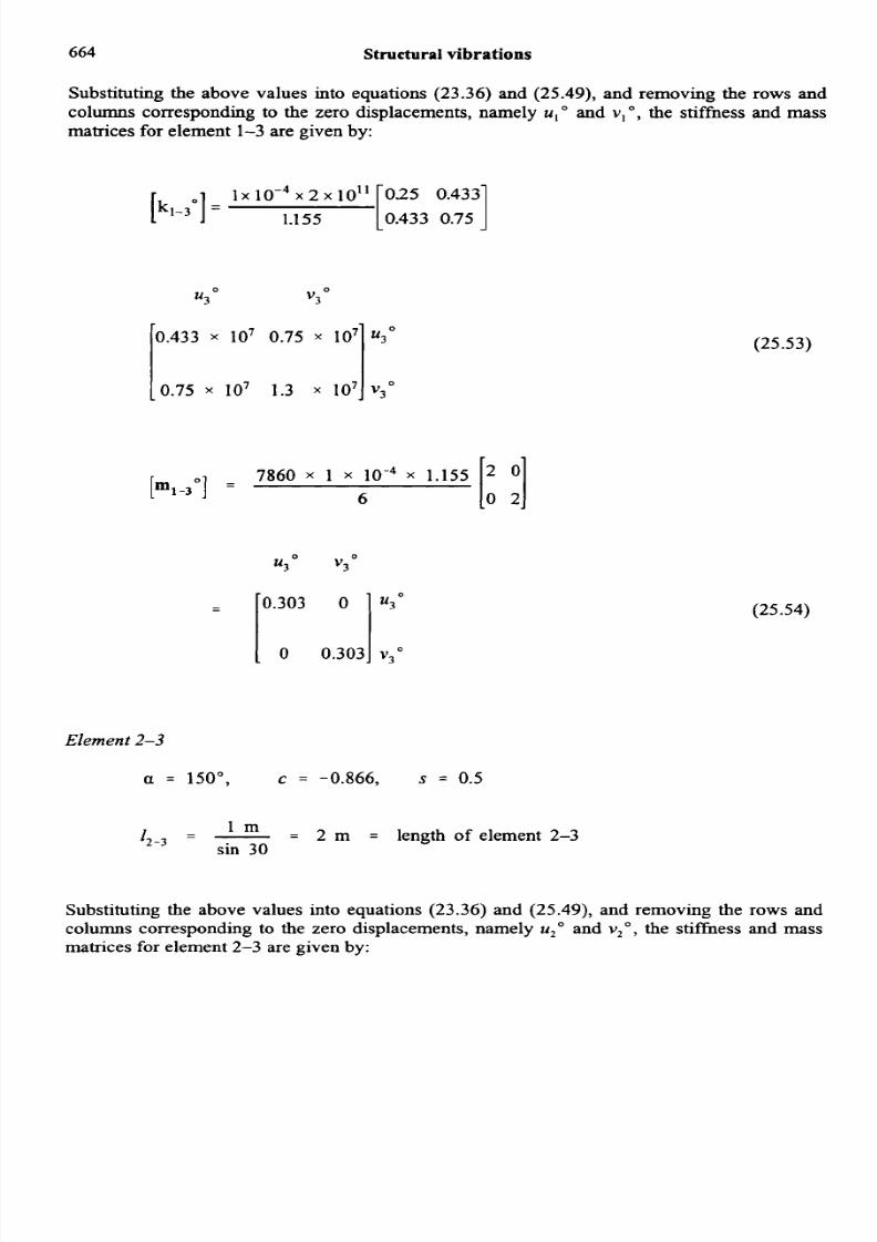
Substituting the above values into equations (23.36) and (25.49), and removing the rows andcolumns corresponding to the zero displacements, namely u ," and v , O , the stiffness and massmatrices for element 1-3 are given by:
U 3 O
v 3 ~
1.1 55 0.433 0.75
7860 x 1 x x 1.155
[m,-3O] = 6
(25.53)
0 21
(25.54)
Element 2-3
u = 150", c = -0.866, s = 0.5
l m
sin 3012-3 =- 2 m = length of element 2-3
Substituting the above values into equations (23.36) and (25.49), and removing the rows andcolumns corresponding to the zero displacements, namely u," and v,", the stiffness and massmatrices for element 2-3 are given by:

8/14/2019 25 STR VIBRATIONS
http://slidepdf.com/reader/full/25-str-vibrations 23/48
Mass matrix for a rod element
=
665
0.75 x lo 7 -0.433 x 10'
-0.433 x lo7 0.25 x lo 7
-0.433 0.25
1 x 10-4 x 2 1011
2k 2 - 3 O ] =
(25 .55)
(25.56)
The system stiffnessmatrix corresponding to the free displacements u3 " and v j 0 s obtained byadding together equations (25.53) and (25.55), as shown by equation (25.57):
K 1 1 =
v3
1.183 x lo7 0.317 x lo7 u j o
0.317 x lo7 1.55 x IO7 V 3 01(25.57)
(25 .58)

8/14/2019 25 STR VIBRATIONS
http://slidepdf.com/reader/full/25-str-vibrations 24/48
666 Structural vibrations
The systemmassmatrix corresponding to the free displacem ents u, O and vlo s obtained by addingtogether equations (25.54 ) and (25.56), as shown by equation (25.59 ):
[M,,1 =
llI0
0.303
+OS24
0
v3"
0
0.303
+OS24
Now, from Section 25 .2,
If simple harmonic motion takes place, so that
vc = CeJ""
then,
Substituting equation (25.62 ) into equation (25 .61),
kv c 0- 0 v + - =
' M
(25.59)
(25.60)
(25.61)
In matrix form, equation (25.6 3) becomes
(25.62)
(25.63)
(25.64)
or, for a constrained structure,
8/14/2019 25 STR VIBRATIONS
http://slidepdf.com/reader/full/25-str-vibrations 25/48
Mass matrix for a rod element 667
( F l ] - a2 MlJ (u,} = 0 (25.65)
Now, in equation (25.65), the condition {u,} = (0) is not of practical interest, therefore the
solution of equation (25.65) becomes equivalenttoexpanding the determinant of equation (25.66):
I [ 4 1 ] -a2 "ll] I = 0 (25.66)
Substituting equations (25.58) and (25.60) into equation (25.66), the following is obtained:
1.183 x lo7 0.317 x lo7 0.827 0
0.317 x lo7 1.55 x lo7I 0 0.8271(25.67)
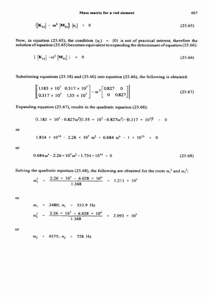
Expanding equation (25.67), results in the quadratic equation (25.68):
(1.183 x 10⁷-0.827~2)(1.55 107-0.827~2)-(0.317 107)2 = 0
or
1.834 x 10¹⁴ - 2.26 x lo7 o2 + 0.684 o4 - 1 x l o i 3 = 0
or
O.684o4-2.26x 10702+ . 7 3 4 ~ 1 0 ' ~0 (25.68)
Solving the quadratic equation (25.68), the following are obtained for the roots w,' and0'':
2 2.26 x lo7 - 6.028 x lo6 = 1.211 1070' =
1.368
or
o1 = 3480; n, = 533.9 HZ
o* =2.26 x lo7 + 6.028 x lo6 = 2.093 107
1.368
or
o2 = 4575; n, = 728 Hz

8/14/2019 25 STR VIBRATIONS
http://slidepdf.com/reader/full/25-str-vibrations 26/48
668 Structural vibrations
To determine the eigenm odes, substitute q2nto the first row of equation (25.67) and substitutew into the second row of equation (25 .67), as follows:
(1.183 x l o 7 - 34802 x 0 .827 )~; t 0.317 x lo' v i = 0 (25.69)
1.815 x lo 6 u< -t 3.17 x lo 6 v ~ O 0
Let,
U 3 O = 1
: v30 = -0.47
so that the first eigenm ode is:
[u30 v3"] = [ l - 0.471 see the figure below at (a) .
Similarly, to determine the second eigenmode, substitute 022 into the second row of equation
(25.67), as follows:
0.317 x lo7 u30 + (1.55 x lo7 - 0.827 x 4575*) v30 = 0
or
0.317 x lo7 u30 - 1.81 x lo6 v30 = 0
Let,
v30 = 1
: u3 = 0.57
so that the second eigenmode is given by
[uJ0 vJo] = [0.57 11 see below at(b).
(a) First eigenmode.
8/14/2019 25 STR VIBRATIONS
http://slidepdf.com/reader/full/25-str-vibrations 27/48
Mass matrix for a rod element 669
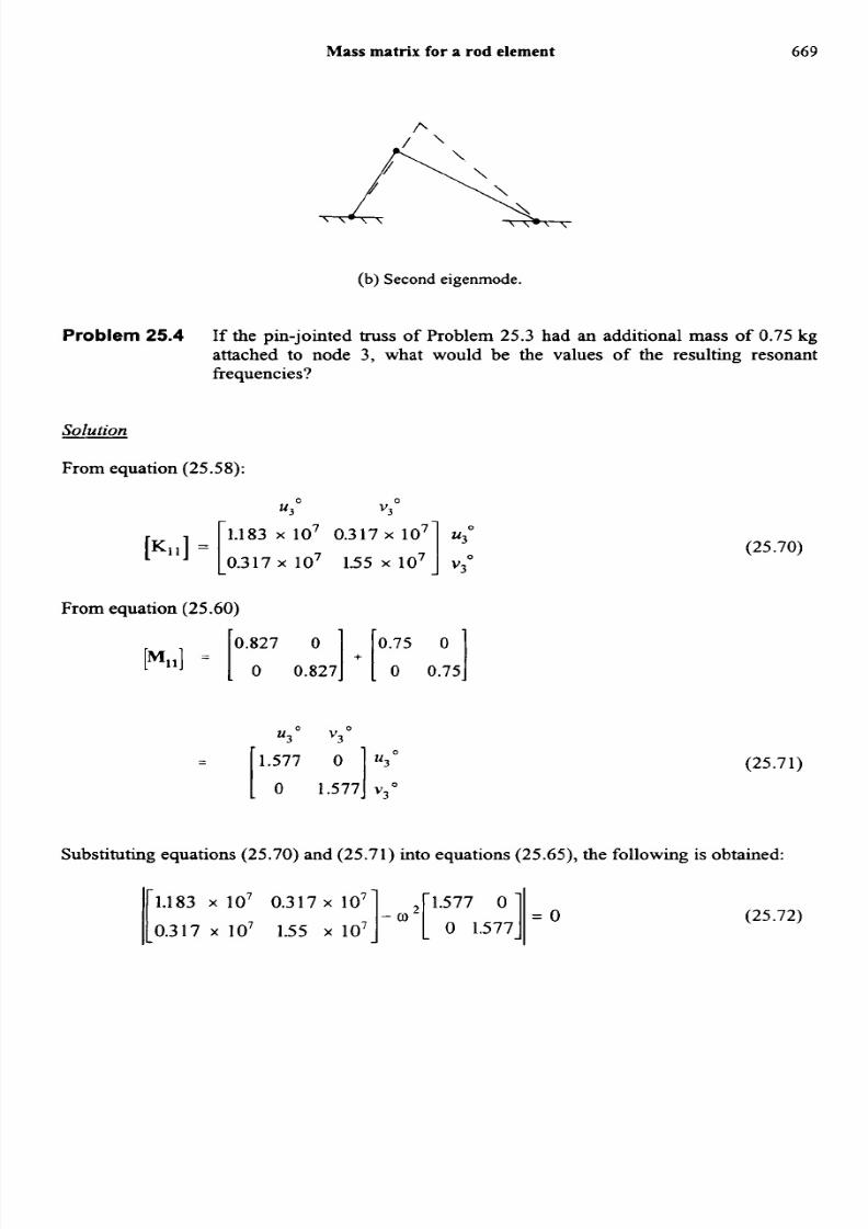
(b) Second eigenmode.
Problem25.4 If the pin-jointed truss of Problem 25.3 had an additional mass of 0.75 kg
attached to node 3, what would be the values of the resulting resonantfrequencies?
Solution
From equation (25.58):
U 3 O v3"
l .317 x io7 155 x io71 v,"1.183 x lo7 0.317 x lo7 u (25.70)K11]
From equation (25.60)
0.827 0.75 0
[M111 = [ 0 O.:27l + [ 0 0.711
u30 v30
(25.71)
= [ 'Y7 ,R,] r:'Substituting equations (25.70) and (25.71) into equations (25.65), the following is obtained:
1.183 x l o 7 0 . 3 1 7 ~o7 1.577 0
]- a2 [ 0 1.57711= O.317 x lo7 1.55 x lo7(25.72)
ll
8/14/2019 25 STR VIBRATIONS
http://slidepdf.com/reader/full/25-str-vibrations 28/48
670 Structuralvibrations
Expanding the determinantof equation (25 .72 ), results in the quadratic equation (25.73 ):
(1.183 x lo 7 - 1.5770’) (1.55 x l o 7 - 1.5770’) - (0.317 x 10⁷)2 = 0
or
1.834 x l O I 4 - 4.31 x lo 7 a2 2.487 o4 - 1 x I O i 3 = 0
or
2 . 4 8 7 0 ~ - 4.31 x l o 7 o2 1.734 x I O i 4 = 0 (25.73)
The quadratic equation (25.73 ) has two roots, namely q2nd 022, which are obtained as follo ws :
2 4.31 io7 - 1.178 io7 = 6.297x ],,6O l =
4.974
mi = 2509; n, = 399.3 Hz
and
2 4.31 x IO7 + 1.178 x IO’ = 1 . 1 0 3 107w2 =
w2 = 3322; n2 = 528.6 Hz
4.974
Problem25.5 Determine the resonant frequencies and eigenm odes for the pin-jointed space
truss of Problem 2 3.3, given that,
A = 2 x 1 0 . ~ ~ ~
E = 2 x 10” Nlm2
p = 7860kgJm’
Solution
Element 1 4
From Problem 25 .3 ,
I = 10m

8/14/2019 25 STR VIBRATIONS
http://slidepdf.com/reader/full/25-str-vibrations 29/48
Mass matrix for a rod element 67 1
7860 x 2 x x 10
[m,-4O] = 6
Substituting this and other values into equation (25.50), and removing the rows and columnscorrespondingto the zero displacements,namely u1 , vI and w1 , the massmatrix for element 1-4is given by
2 0 0
.o 0 2
5.24 0 0
0 5.24 0
0 0 5.24
Element 2-4
'4'
V 4 O
w40
From Problem 25.3,
I = lOm
(25.74)
(25.75)
Substituting this and other values into equation (25.50), and removing the rows and columnscorresponding to the zero displacements, namely u20,vzoand wzo,he mass matrix for element2-4 is given by
15.24 0 0
U 4 O V 4 O W4O
u4 O
v4 O
w4 O
1 0 0 5.24
(25.76)
Element 4-3
From Problem 25.3,
I = 10m

8/14/2019 25 STR VIBRATIONS
http://slidepdf.com/reader/full/25-str-vibrations 30/48
672 Structural vibrations
Substituting he above and other values into equation (25.50),andremoving the rows and columnscorresponding o the zero displacements, namelyu3 , v3O andwjO , themassmatrix for element 4-3is given by
[m4-3°]
u40 V 4 O W4O
5.24 0
0 5.24 0(25.77)
Toobtain [M, I, the system mass matrix corresponding to the free displacementsuq0, ,," andw,",the elemental mass matrices of equations (25.75) to (25.77), are added together, as shown by
equation (25.78):
15.72 0
[M1lo] = 1 0 15.72
l o 0 15.721 w40
From equation (23.62),0 0
u4 v4 W4O
(25.78)
(25.79)
10 0.832 6 1 w40
Substituting equations (25.78) and (25.79) into equation (25.65), the following determinant is
obtained:
i2 0 0 ] !'p2 0 ]I x lo6 0 4 0.832 -02 0 15.72 0
0 0.832 6 0 15.72
(25.80)
From the top line of equation (25.80):
2 x IO 6 - 15.720' = 0
8/14/2019 25 STR VIBRATIONS
http://slidepdf.com/reader/full/25-str-vibrations 31/48
Mass matrix for a rod element
or
673
lo6 - 1.272 x lo5" 1 = - -
2
15.72
o1 = 356.7, n = 56.76 Hz
As the first line of equation (25.80) is uncoupled, this equation can be reduced to the 2 x 2determinant of equation (25.81):
0.832 15.72
1 ' lo6[0.;32 6 0 17d I =
Expanding equation (25.81), the quadratic equation (25.82) is obtained:
or
2.4 x 10¹³ - 1.572 x 10'0~ + 247.120~ - 6.922 x 10" = 0
or
247.120~- 1.572x 10'0~ +2.33x l O I 3 = 0
Solving equation (25.82), the roots w and are obtained, as follows:
= 2.361 x IO51.572 x 10' - 0.41 x lo8
O2 =
492.24
o2 = 485.9; n2 = 77.32 Hz
2 1.572 x lo8 + 0.41 x lo8 = 4.026 105O3 =
492.24
(25.81)
(25.82)
o3 = 634.5; n3 = 100.98 Hz
8/14/2019 25 STR VIBRATIONS
http://slidepdf.com/reader/full/25-str-vibrations 32/48
67 4 Structural vibrations
To determine the eigenmodes
By inspection of the first line of equation (25.80),
u4" = 1 , v," = 0 and w," = 0
Therefore, the first eigenmode is
[u4" v," w4"] = [ l 0 01
To obtain the second eigenmode, substitute 0.122 into the second line of equation (25.80) to give
0 x u4" + [4 x IO6 - (485.92 x 15.72)]v4" + 0.832 x 10⁶w," = 0
or
Let,
0 . 2 8 9 ~ ~ "0 . 8 3 2 ~ ~ " 0 (25.83)
v," = 1
: w,"= - 0.347
Therefore, the second eigenmode is
[u," v," w,"] = [0 1 - 0.3471
To obtain the third eigenmode, substitutea into the third line of equation (25.80) to give
0 x u," + 0.832 x lo6v," + (6 x lo6 - 634.S2 x 15.72) w," = 0
or
0.832 v," - 0.329 w4' = 0
Let,
w4" = 1
: v," = 0.395
Therefore, the third eigenmode is
[u," v4' w,'] = [0 0.395 11
(25.84)

8/14/2019 25 STR VIBRATIONS
http://slidepdf.com/reader/full/25-str-vibrations 33/48
Mass matrix for a rod element 675
Determine the resonant frequencies for the tripod ofProblem25.5, if this tripod
has a mass of 10 kg added to node 4.
Problem25.6
2 0 0 -[K,,] I x106
0 4 0.832
0 0.832 6 -
Solution-
U 4 O
V4 O
wq0
From equation (25.79),
U q 0 vqa W4O
15.72 0 0
[MI,] = 0 15.72 0 +
0 0 15.72
10 0 0
0 10 0
0 0 10
25.72 0 0 .,
0 25.72 0
0 0 25.72
v4'
w40
(25.85)
[2 0 0 1 *I2172 0 0 10 0.832 6 0 25.72
1 x lo6 0 4 0.832 - 0 0 25.72 0
(2 5.86)
= 0
Substituting equations (25.85) and (25.86) into equation (25.65), the following determinant is
obtained:
From the first line of equation (25.65):
- 7.776 x io4- -x IO6
25.72
(25.87)
W , = 2789; n, = 44.1 HZ

8/14/2019 25 STR VIBRATIONS
http://slidepdf.com/reader/full/25-str-vibrations 34/48
676 Structural vibrations
As first line is uncoupled, the determinant of equation (25.87) can be reduced to the 2 x 2
determinant of equation (25.88):
4 0.832 25.72 0
I l x 106[ 0.832 6
1-4. 25.72 ] i = o
(25.88)
Expanding the determinant of equation (25.88), the following quadratic is obtained:
(4 x lo6- 25.72 a') (6 x lo6- 25.72 w') - (0.832 x 10⁶)2= 0
or
2.4 x lO I3 - 2.572 x 10' w2 + 661.5 w4 - 6.92 x 10" = 0
or
661.5 w4 - 2.572 x 10' w2 + 2.33 x l O I 3 = 0 (25.89)
Solving equation (25.89),
2 2.572 x lo8 - 0.671 x IO 8 - 1.437 x 10⁵W2 = -
o2 = 379.1; n2 = 60.3 Hz
1323
= 2.451 x lo52.572 x 10' + 0.671 x lo8
w3 =
wg = 495.1; n3 = 78.8 Hz
1323
25.10 Mass m atrix for a beam element
The beam element, which has four degrees of freedom, is shown in Figure 25.9.
Figure 25.9 Beam element.

8/14/2019 25 STR VIBRATIONS
http://slidepdf.com/reader/full/25-str-vibrations 35/48
Mass matrix for a beam element
A convenient polynomial with which to describe the lateral deflection v is
and
677
(25.90)
(25.91)
In equation (25.90), it can be seen that the polynomial has four arbitrary constants, and thiscorresponds to the four degrees of freedom, namely, vI, ,, v2 and e i.e.
Atx = 0, v = V I and 8, = -(dv/dx),
Atx = 1, v = v, and 8, = -(dv/dx),,
Substituting the first two boundary conditions into equations (25.90) and (25.91):
a, = v,
and
= - e ,
Substituting the remaining two boundary conditions into equations (25.90) and (25.91), thefollowing two simultaneous equations are obtained:
V, = v, - e,i + a,/, + 4 3 (25.92)
and.
e, = 8, - 2u,l- 3aJ2(25.93)
Multiplying equation (25.92) by 211, we get:
27 y2 - v,) = -28, + 2 a - ~ 2a412 (25.94)
Adding equation (25.93) to equation (25.94):
2
- v2 - v,) + 8,I= 8,-28, - 3aJ2 + 2aJ2
or

8/14/2019 25 STR VIBRATIONS
http://slidepdf.com/reader/full/25-str-vibrations 36/48
678 Structural vibrations
2
I
-a4/’ = - v2 - v , ) + e + e,
a4 = -- (v2 - v,) -(02 + 0,)
l 3 l 2
Substituting equation (2 5.95 ) into equation (25.9 2) :
v2 - v1 + e,/ = q 2 2 h 2 - - (e2 + e,) z
Substituting the above values of a , to a4 nto equation (25 .90)
x3
- 2 t 2 ( v 2 - v , )+ 7 & 2 + 0,)
or
v = ~ , ( 1 - 3 { ~ + 2 ( ~ ) + 8 , 1 (5 + 2 t 2 - t3 )
+ v 2 ( 3 t 2 - 2 t 3 ) + e 2 z ( ~ 2t 3 )
where,
< = x / l
i .e.
v = 1 (1 -3 t2 + 2 t3 ) 1 ( - 5 + 2 c 2 - 5))
(25.95)
(2 5.96)
(25.97)
(25.98)

8/14/2019 25 STR VIBRATIONS
http://slidepdf.com/reader/full/25-str-vibrations 37/48
679ass matrix for a beam element
where [N] is a matrix of shape functions for a beam element:
[N] = [(1-3t2 + 2t 3)I (- j + 2 t 2 - t3)(3t2-2t3)1(t2 - t')] (25.99)
From equation (25.38):
[ml = l o ' [NIT P[NI AI d 5 (25.100)
Substituting equation (25.99) into equation (25.100), and integrating, the mass matrix for a beam
element is given by
VI 8, v2 8,
156
-221 412
54 -131 156
131 -312 221 41
(25.101)
Equation (25.101) is the mass matrix of a beam element due to the self-mass of the structure, but
ifan additional concentratedmass is added to node i, the following additional components ofmassmust be added to equation (25.102) at the appropriate node.
Added mass matrix at node i
(25.102)
whereMMI is the mass moment of inertia andM, s the mass.
Problem 25.7 Determine the resonant frequencies for the beam of the figure in Problem 23.4,
assuming that the 4 kN load is not present, and that
E = 2 x 10"N/m2, p = 7860 kg/m3
A = 1 x m2, I = 1 x 1 0 . ' ~ ~

8/14/2019 25 STR VIBRATIONS
http://slidepdf.com/reader/full/25-str-vibrations 38/48
680 Structural vibrations
Solution
Element 1-2
I = 3 m
Substituting the above value of 1 into equation (25.101), together with the other properties of this
element, and removing the columns and rows correspondingto the zero displacementsv,and e,,the elementalmass matrix is given by
7860 1 3 156 66 V 2
420 [ 66 361 0,
[ml-z] =
Element 2-3
I = 2 m
v2 02
0.876 0.371 v2
0.371 0.2021 0,
(25.103)
Substituting the above value of I into equation (25.101), together with the other properties of this
element, and removing the columns and rows corresponding to the zero displacementsvj and ethe elemental mass matrix is given by:
(25.104)
The system mass matrix [M, , ] is obtained by adding together the elemental mass matrices ofequations (25.103) and (25.104):
v2 0
[Mll] = [ 1.46 0.2061 v 2
0.206 0.262 0,
(25.105)
From equation (25.84),

8/14/2019 25 STR VIBRATIONS
http://slidepdf.com/reader/full/25-str-vibrations 39/48
Mass matrix for a beam element 68
38 880 -16 660 v 2
-16 660 66 660 1 8,[Kll] = [ (25.106)
Substituting equations (25.105) and (25.106) into equation (25.65), the following determinant is
obtained:
38 880 -16 6601 [ 1.46 0.2061 1-16 660 66 660 0.206 0.262
-w 2 = o (25.107)
Expanding the determinant of equation (25.107), the following quadratic equation is obtained:
(38 880 - 1.460~) 66 660 - 0.2620~)- (- 16 660 - 0.2060~)~ 0
or,
2592 x lo6 - 0.107 X lo6w2 + 0.383 w4
278 x lo6- 6864 w2 - 0.042 w4 = 0
0.341 w4 - 0.1 139 x lo6w2 + 2.314 x lo9 = 0 (25.108)
The roots of equation (25.108), namely, w I2and 022, can real ly be shown to be:
2 0.1139 x lo6 - 99 080 = 2.173 104w, =
0.682
or
w1 = 147.4; n I = 23.45 Hz
2 0.1139 x lo6 + 99 080 = 3.123 105w2 =
0.682
and,
w2 = 558.8; n2 = 88.93 Hz
To obtain the first eigenmode, substitute w I 2 nto the first line of equation (25.107), to give

8/14/2019 25 STR VIBRATIONS
http://slidepdf.com/reader/full/25-str-vibrations 40/48
682 Structural vibrations
(38 880 - 1.46 x 147.4,) v, + (- 16660 + 0.206 x 147.4,) 8, = 0
or
7 m V ,- 21 m e , = o (25.109)
i.e.
[v, e,] = [1 0.3391- see the figure below at (a).
To obtain the second eigenmode, substitute 022 into the second line of equation (25.107) to give:
(- 16 660 - 0.206 x 558.8,) v2 + (66 660 - 0.262 x 558.8’) 8, = 0
or,- 80 985 v, - 15 150 e, = o (25.1 10)
i.e.
[v2 e,] = [- 0.187 13 -see the figure below at (b).
(b) Second eigenmode
Problem 25.8 If the beam of Problem 25.7 has a mass of 1 kg, with a mass moment of inertia
of 0.1 kg m2added to node 2, determine the resonant frequencies of the beam.
Solution
From equation (25.105)
[Mil] = [ 1.46 0.2061 + [ 1 O ]
0.206 0.262 0 0.1

8/14/2019 25 STR VIBRATIONS
http://slidepdf.com/reader/full/25-str-vibrations 41/48
Mass matrix for a beam element
v2
= [ 2.46 02 V2
0.206 0.362 e,
From equation (25.101),
38880 -16660
[K1ll = [ -16660 666601
Substituting equations (25.1 11) and (25.1 12) into equation (25.65),
38 880 -16 6601
[2.46 0.2061 I = o
-16 660 66 660 0.206 0.362-0,
683
(25.1 11)
(25.1 12)
(25.1 13)
(38 880 - 2.46 a2)66 660 - 0.3620’) (16 660 + 0.206 0’)’ 0
or
0.259 X 10” - 0.178 X lo66.1’+ 0.891 0.1~ 2.776 x lo*- 68640’ 0.042 m4 = 0
or
0.849 a4- 0.1849 x lo 6m2+ 0.231 x 10’’ = 0 (25.1 14)
Solution of the quadratic equation (25.1 14) results in the roots and 022, as follows:
2 0.1849 x lo6 - 0.162 x lo6 = 1.394 10 40, =
1.698
or
0, 116.1; n1 = 18.48 Hz
and,
2 0.1849 x lo6 + 0.162 x IO6 = 2.043 1050, =
1.698
or
o2 = 452; n, = 71.93 Hz

8/14/2019 25 STR VIBRATIONS
http://slidepdf.com/reader/full/25-str-vibrations 42/48
684 Structural vibratiens
25.11 Mass matrix for a rigid-jointed plane frame element
Prior to obtaining the mass matrix for an element of a rigid-jointed plane m e , t will be necessaryto ob tain the mass matrix for the inclined beam of Figure 25.10.
The mass matrix for an inclined beam element in globa l co-ordinates is
[mbO1 = W I T ml [DCI (25.115)
where,
[DC] is given equation (25.85) and [m] is given by equa tion (25.101).
Figure 25.10 Inclined beam element.

8/14/2019 25 STR VIBRATIONS
http://slidepdf.com/reader/full/25-str-vibrations 43/48
Mass matrix for a rigid-jointed plane frame element 685
For the element of a rigid-jointed plane frame, the elemental mass matrix in global co-ordinates
is given by
where [qo]s the axial part of the mass matrix of a rod element:
I 2 0 0 1 0 0 1
(25.118)
0 0 0 0 0 0
l o 0 0 0 0 4where, in equation (25.118), the components of mass in the v displacement direction have been
removed, because they have already been included in [mho].
Substituting [DC] ffom equation (25.85) into equation (25.118):
!C
!cs 2s2
0 0 0
c 2 cs 0 2c2
cs s 2 0 2cs 2s2
0 0 0 0 0 0
(25.1 19)
From equations (25.1 16) and (25.1 18), it can be seen that application of these elemental mass
matrices, together withthe elemental stiffness matrix of equation (25.85), to a realistic rigid-jointedplane frame will be extremely difficult without the aid of a computer.
Equation (25.1 17) shows the mass matrix for the self-mass of an element of a rigid-jointed
plane frame, but if the effects of an additional concentrated mass are to be included at a particular
node, the concentrated mass must be added to the appropriate node, as follows:

8/14/2019 25 STR VIBRATIONS
http://slidepdf.com/reader/full/25-str-vibrations 44/48
68 6
U,o v ,o e,
Ma 0 0
0 Ma 0
0 0 MMI
Structural vibrations
(25.120)
where
Ma = thevalueofthemss
MMI = the mass moment of inertia of this mass
25.12 Units in structural dynamics
Considerable care should be taken in choosing suitable units in structural dynamics.
Recommended units are as follows:
(1) Imperial
Mass (lbf s2/in);density (lbf s2/in4);E (lbf/in2); time(s); length (in);Force(1bf); second moment
of area (in4); cross-sectional area (in').
(ii) SI
Mass (kg); density (kdm3);E (N/m'); time (s); length (m); Force(N); second moment of area
(m4); cross-sectional area (m2).
(iii) Derived SI
Mass (kg); density (kglmm3); E (d /m m2 ); ime (s); length (mm); force(mN); second moment
of area (Ilun"); cross-sectional area (mm').
Further problems answers on page 698)
25.9 A doubly symmetrical beam consists of a hollow rectangular steel section, having the
cross-section shown, and of length 10m. It is simply-supportedin bending about bothaxes Cx, Cy at the ends. Estimate the lowest few natural frequencies of lateral vibrations
of the beam about the axes Cx and Cy. Take E = 200 GN/m'.
8/14/2019 25 STR VIBRATIONS
http://slidepdf.com/reader/full/25-str-vibrations 45/48
Further problems 687
25.10 If the beam of Problem 25.7 cames an axial thrust of lo3kN, what is the lowest natural
frequency of the beam?
25.11 A light, uniform cantilever, of lengthL and uniform flexural stiffness EI, cames a massM at the free end. Estimate the natural frequency of vibrations.
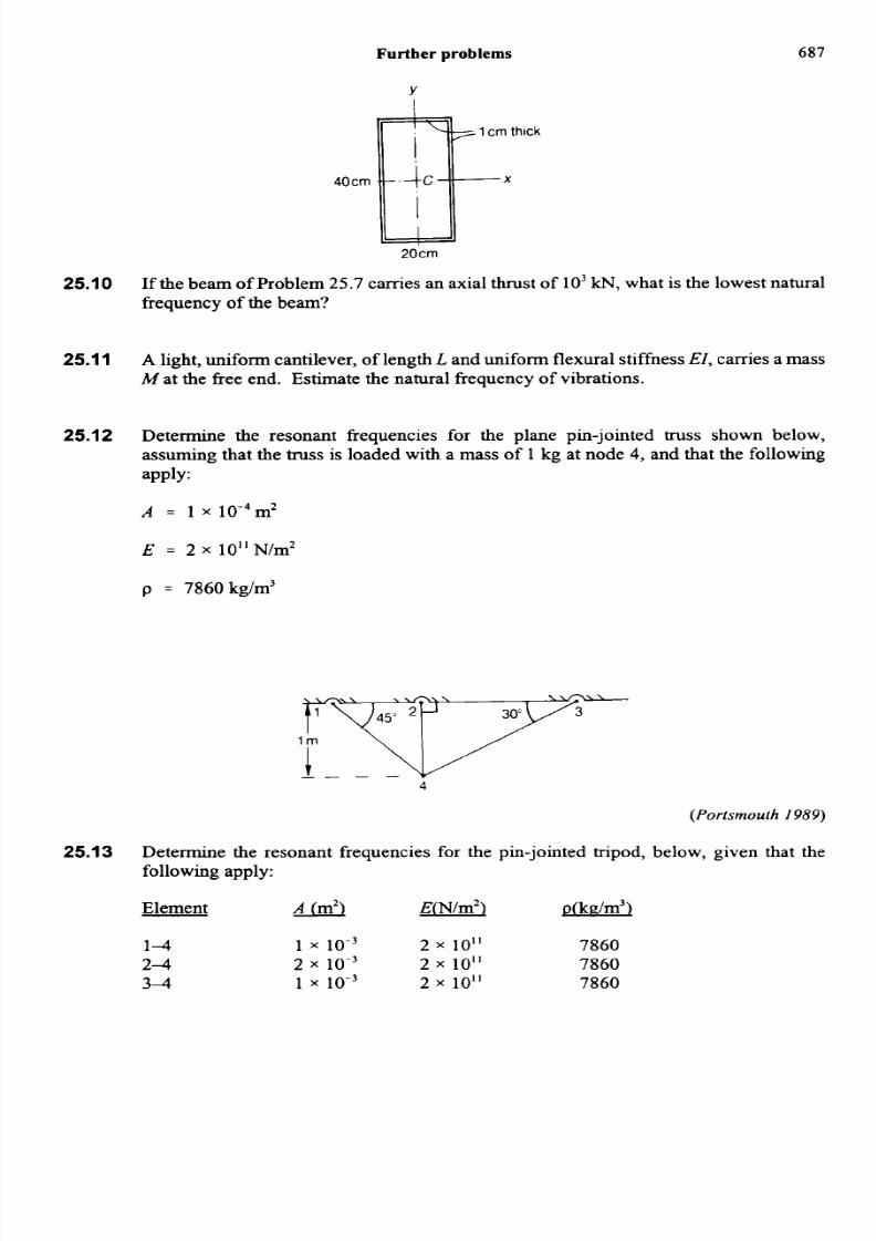
25.12 Determine the resonant frequencies for the plane pin-jointed truss shown below,
assuming that the truss is loaded with a mass of 1 kg at node 4, and that the following
apply:
A = 1 x 10⁻⁴m2
E = 2 x 10" N/m2
p = 7860kg/m3
(Portsmouth 1989)
Determine the resonant frequencies for the pin-jointed tripod, below, given that thefollowing apply:
Element A (m2) E(N/m2) p(kn/m3)
1-4 1 x 10.~ 2 x 10" 7860
2-4 2 x 10 .~ 2 x 10" 78603 4 1 x io-3 2 x 10" 7860
25.13

8/14/2019 25 STR VIBRATIONS
http://slidepdf.com/reader/full/25-str-vibrations 46/48
688 Structural vibrations
(Portsmouth 1983)
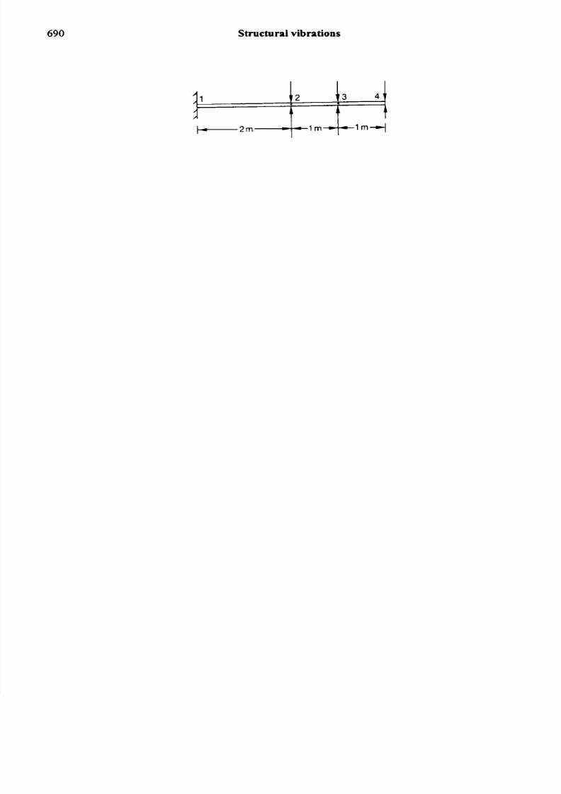
25.14 A continuous beam is fixed at the nodes 1 and 4, and simply-supported at the nodes 2
and 3, as shown in the figure below.Determine the two lowest resonant frequencies of vibration, given the following:
E = 2 x 10"N/m2
p = 7860kg/m3
Element A (m2) I(m4',
1-2 1 x io-4 1 x io-7
2-3 2 x io-4 2 x io-7
3-4 1 x 1 0 - ~ 2 x 1 0 . ~

8/14/2019 25 STR VIBRATIONS
http://slidepdf.com/reader/full/25-str-vibrations 47/48
Further problems 689
(Portsmouth 1987)
25.15 A continuous beam is fured at the nodes 1 and 5, and simply-supported at the nodes 2,3 and 4, as shown below.
Determine the two lowest resonant frequencies of vibration given the following:
E =
2x
10”N/m2
p = 7860kg/m3
Element A (m2) T(m4)
1-2 1 x io-4 1 x 10.’
2-3 2 x 1 0 - ~ 2 x io-7
3 4 2 x 1 0 - ~ 2 x io-7
4-5 1 x 10.~ 1 x 10.~
(Portsmouth 1987. Honours)
25.16 Calculate the three lowest natural frequencies of vibration for the continuous beambelow, where
A = 0.001 m2
I = 1 x 1 0 - ~ m ~
E = 2 x 10” N/m2
p = 7860 kg/m3
8/14/2019 25 STR VIBRATIONS
http://slidepdf.com/reader/full/25-str-vibrations 48/48
690 Structural vibrations