25 - saiful aminsaifulamin.info/publication/conference_proceeding/c25.pdf · design charts for...
TRANSCRIPT
[email protected]/VIL-COMPU<'£dln,n""So,,,,ndB.HY. Topping. (Editor) ..Advances in Civil and Structural EngineeringComputing/or PractiCl!.Civil-Camp Press. Edinburgh, 241-246
-;.,':
:fj'·;·.A~CONOMIC DESIGN;$XAPPROACH FOR HELICOIDAL~t,·f. . •
:~t.:·;,STAIRSLABS BASED ON FINITE ELEMENT ANALYSIS•t ".~.
{~:~r':""4 :.,i':y '00361
.A.F.M. SaifulAmin and S. Ahmadi:
· :Department of Civil Engineering,Bangladesh University of Engineering and Technology, Dhaka, Bangladesh
..
, Eight-node curved thick shell finite elements were used to,t... ·analyse two· prototype helicoidal stair slabs without any;::.,geometric· idealisation. The results of finite element analysis· ··were compared with those obtained from traditional helical. girder solution. The comparative investigation revealed thathelical girder solution largely over estimates the vertical
"~.moment, lateral.moment, lateral shear force and thrust alongwith an under .estimation of torsion. Finally, for criticaleco!Jomic assessment, one of the prototype stairs wasdesigned following ACI ultimate strength design method.. The design exercise indicated that around 47% saving of the.reinforcement required in resisting the mioments and thrustcan be achieved in FE approach with an overall economy ofaround 17%.
, The helicoidal stair has an inherent fascinating appearanceamong different forms of stairs from architectural point of
., view. For this reason, helicoidal. stair slabs are increasinglyt;> being . used nowadays in many important buildings.~::'Geometrically, a helicoidal surface is a three dimensional:{: structure in space consisting of a warped surface which is~':'··geh~Eatedby moving a straight line touching a helix so that• .; the movirigline' is always perpendicular to the axis of the;::. helix. In an oblique helicoid, the generating line always',' 'maintains a fixed angle with the helix. Because of this:.:complex geometric configuration, the traditional methods of• analysis of helicoidal stairs are based on various idealisations, and assumptions. There are two basic approaches. ', ' In the first approach [I], the simplest solution is produced" by reducing the helicoid to its horizontal projection and, resolving the problem into that of a fixed ended curved beam.: The structure is thus idealised as a two dimensional structure.
The second approach [2, 3, 4, 5] considers the helicoid as a", helical girder (a space structu~e). In this approach, the helicoid;', is reduced to its .elastic line having the same stifTness as that of'.':' original structure. Comparative assessment [6] of these two,'~.approaches showed that curved beam solution [1] leads to a" very conservative estimation of forces.
The efTorts on the development of an 'exact' procedure of;' ~~lysis of helicoidal stair reached its culmination through the<,works of Santathadapom and Cusens [7], where the stair was':~assumed as a helical girder. TI1e work presented thirty six
design charts for helical stairs of a wide range of geometricparameters. Based on this work, four design charts werecompiled in somewhat modified form in current design hand.books [8]. These design charts now stand as 'helical girdersolution' for helicoidal stairs.
But both curved beam and helical girder solution fail totake into account the three dimensional characteristics of .helicoid and its inherent structural efficiency. With a view todeveloping an 'exact' and general solution, 'Menn [9] outlinedan .analytical method of solving helicoidal shell problemsincluding edge perturbatiOns or edge conditions. It wasobserved that the analysis of a helicoidal shell for certainboundary conditions is possible through highly complexmathematical calculations. Menn realised the f";Jct andconcluded fmaIly to go for 'girder solution'.The situation has now changed. The dcvelopment of
difTerent general curved sheIl elements in the field of finiteelement (FE) techniques and the availability of high speed-digital computers at design engineers' desk have ushered in anew hope for the shell solution of this problem by FE method ina more logical and convenient way. But until now, no efTort inthis direction has been reported regarding the behaviour of thisstructure u'nder unifonnly distributed vertical loadings.The main objective of. the 'present investigation was
therefore aimed to study the actual behaviour Of thehelicoidal stair slab in FE approach without any geometricidealisation and to make a comparative assessment betweenthe helical girder solution [8] and the FE method of analysisin terms of economy, as earlier the curved thick sheIl element[10, 11, 12, 13] performed well in developing an economicdesign basis for dog-legged stairs (14, 15] and free standingstairs [16]. Based on this experience, the thick shell clementwas used to analyse two prototype fixed ended reinforcedconcrete helicoidal stair slabs. The stairs wcre analysed forthe given geometry as h'elical girders as well. Finally, for aneconomic assessment, one of the prototype stairs wasdesigned by using the results of both approaches. The paperpresents some significant results of the work. .
TIlC helicoidal stairs at Kamalapur Railway Station (Stair-I)and Sena Kalyan Bhaban (Stair-II) in the city of Dhaka,Bangladesh were selected for the present study. These twostairs arc in service. The geometric dimensions of thesestructures were surveyed and are tabulated in Table I alongwith specified loading condition.
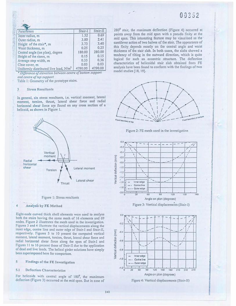
~'i:'-;)..•.~ Parar eters Stair-I Stair-IIA ..Inner radius, m 1.52 0.69", Outer radius, m 3.80 2.41~~ Height of the stair*, m 3.73 3.40}; Waist thickness, m 0.25 0.25<' Central angle (on plan), degree 180.00 280.00
Height of the risers, m 0.15 0.15Average step width, m 0.33 0.36Clear cover, m 0.03 0.03Uniformly distributed live load, N/m2 4790.00 4790.00'Difference of elevation between centre of bot/om supportand centre of top supportTable I:Geometry of the prototype stairs.
In general, six stress resultants, i.e. vertical moment, lateralmoment, torsion, thrust, lateral shear force and radialhorizontal shear force arc found on any cross section of ahelicoid, as shown in Figure I.
Verticalmoment
Radialhorizontalshear
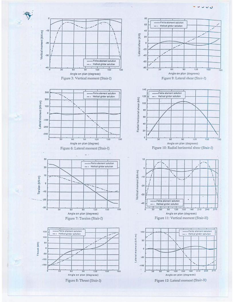
Eight-node curved thick shell elements were u~ed to analyseboth the stairs having the same mesh of 16 clements and 69n?des. Figure 2 illustrates the mesh used in the investigation.:Igures 3 and 4 illustrate the vertical displacements along theInner e?ge, centre line and outer edge of Stair-I and Stair-II,respectIvely. Figures 5 to 10 present the computed verticalmoment, lateral moment, torsion, tlmJst, lateral shear force andr~dial horizontal shear force along tlle span of Stair-I andFIgures II to. 16 pre3ent tllOse of Stair-II due to the applicationof dead an~ live loads. The helical girder solutions have simplybeen supenmposed here for comparison.
For h~licoid~ with central angle of 180°, the maximumdeflectIOn (Figure 3) occurred at the mid span. But in case of
280° stair, the maximum deflection (Figure 4) occurred atpoints away from the mid span with a pseudo fixity at themid span. This interesting feature may be v.isualiscd as the'cantilever action of two halves of the stair. TIle appearance ofthis fixity depends' mostly on the central angle and waistthickness of the stair slab. In both cases, the slabs showed atendency of tilting in the outward direction, which is quitelogical for such an eccentric structure. The deflectioncharacteristics of helicoidal stair slab obtained from FEanalysis have been found to conform with the findings of twomodel studies [18, 19].
I /" \ I / I'- ,,-\1/ /,,/'- "1//
- - '- ~'\'I/_/ _-Fj:r.~bOUtld:"'Y,",fIOl) - - ~ --
0.0~. t- __
·0.2 '.'-'."\ "·0.4
E -0.6oSc ·0.80= -1.0~=Ql ·1.2"0
ro ·1,4u= I
~ ·1.6
·1.8
·2.00
.- .-. i,\ il\ :1" 7. /'
Inner edge.... .-.-_. Certre line
i!
- •• O-Jler edge
Angle on pl,m (degrees)
Figure 3: Vertical displaceme~ts (Stair-I)
~.-f.._ 1-- I- - f- - - 1 - v.\" - .
/1
"- -' 1", .- ...... . ....... ,-
'.\ -" 1
"...... . /.-.- Inner edge_. Ccrtre line
- •• C>.Jleredge
E ·0.4oS5.." ·O.Gd{'iii'0
~·0.8
~ ·1.0
30 60 90 120 150 180 210 2.10 210
Angle on pl;Jn (degrees)
Figure 4: Vertical displacemellts (Stair-I])
~.).;.~ . ..... .""._", ----. ". '. /- ......
I -. \I \
I \I
I \I \
I -- Fnite elemenl solu~on I_.Helical girdor solulion
·10EZ6C~ -20
0E~.!'!t:: ·30
'">
Angle on plan (degrees)
Figure 5:Vertieal moment (Stair-I)
..... I Fi111e element soluUon I..•.... - . Helical girder solution. .'.'.
"- ..•.. -.. ...•., -.
Angle on plan (degree)
Figure 6: Lateral moment (Stair-I)
--Fi"lile element solution_... Helical girder solution
Angle on plan (degrees)
Figure 7: Torsion (Stair-I)
150
100
Z50
><
~2'" ·50fo-
·100
·1 SO
1 --Fnite elemenl solution I-- Helical gIrder solullon I ...../".-- /.,-- ,.../...-
~ -- ./...-V"/ ..•. .--
GO 00 120
Angle on plan (deorees)
eo
60
40
Z206
'"'" 0.c'"~ -20
'"<0..J -40
·60
~--FnHe elcmf"nl solution l_. Helical gird'" solution I
/...-
",
" ., --- .7---
/ ,"".--'...-../
/
Angle on plan (degrees)
Figure 9: Lateral shear (Stair-I)
__ Fi1lte elemenl solution_. Helical girder solution
Angle on plan (degrees)
Figure 10: Radial horizontal shear (Stair-I)
10
0
EZ~ ·10
C'"E ·200EIiiu
·30't:'">
-40
"..•.... •..•.-,. .// " \
/1 \- --- \'I " / \
I ..•.. \I
II \
~--Filile elementsolu~on I .-. Helical girder s~lution
Angle on plan (degrees)
Figure II: Vertical moment (Stair-H)
100
~Z
SO."<
c:•.E0
E
~ "·50~"...J
,lOa
__ FI'He clemen. ,olut,on J"
...•. I _ .• Helical gIrder solurian./' , " -..
"- " e.-- -.....•..••.... ~ ,.-
" '" ,.•.... . ~,'"
__ Fnite clemenl solution_. HeliCJI girder solution
co'iij(; ·sl-
60 90 120 150 180 210
Angle on plan (degrees)
figure 13: Torsion (Stair-II)
H Finlle element solution_. HeliClI girder solution //.~.-'V-
/ /v·V /
'/ ./ .,L. ....-1'---
/
Z 50
~...0
2.<:.l-
·50
·100
·1~0
60 90 120 150 180 210
Angle on plan (degrees)figure 14: llmlst (Stair-II)
60
40
Z20~~
'"'".<:.on~ ·20
'"iU..J -40
-60
H --Finite element solution
-- He"~1 girder solution /..//
- ...- . V/V -.... t-....... .-
V ,- - .......•••.. /"-'....- r---
'/ ./
/
".....
Angle on plan (degrees)
figure 15: Lateral shear (Stair-II)
l rnlle clement solution-- Helical girder solution
,~
/ "-/ '"V "/
/ ""{I .~
ooסס2
Z 15000~:. ;;;-.•ooסס1'" 5000'8'""§ 0.<:.
g-5000u
'"0:.10000
o JO GO 90 120 150 180 210 240 210
Angle on pl:m (degrees)
figure I G: Radial horizont:Jl shear (St:Jir-ll)
003'34
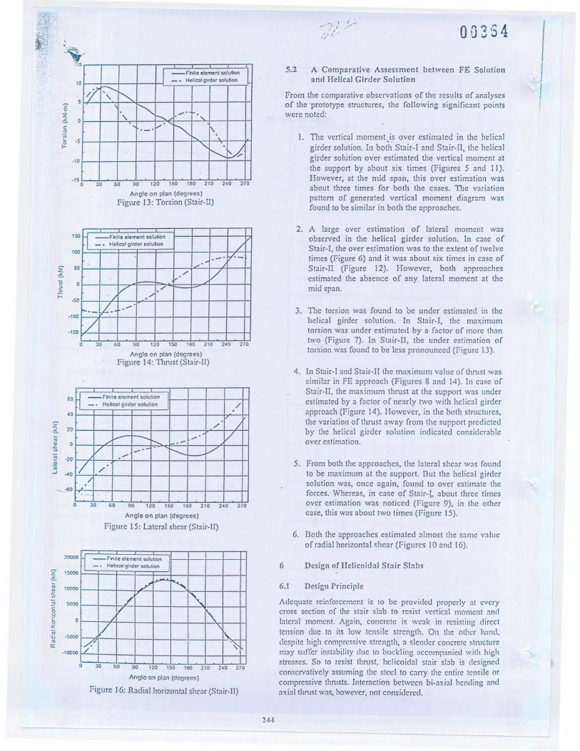
5.2 A Comparative Assessment between FE Solutionand Helical Girder Solution
from the comparative observations of the results of analysesof the 'prototype structures, the following significant pointswere noted:
1. TIIC vertical moment,is over cstimated in the helicalgirder solution. In both Stair-I and Stair-T!, the helicalgirder solution ov'er estimated the vertical moment atthe support by about six times (figures 5 and II).However, at the mid span, this over estimation wasabout three times for both the cases. TIle variationpattern of generated vertical moment diagram wasfound to be similar in both the approaches.
2. A large over estimation of lateral moment W:JSobserved in the helical girder solution. In case ofStair-I, the over es,timation was to the extent of twelvetimes (figure G) and it was about six times in case ofStair-II (Figure 12). However, both approachesestimated the absence of any lateral moment at themid span.
3. TIle torsion was found to be under estimated in thehelical girder solution. In Stair-I, the maximumtorsion was under estimated by a factor of more thantwo (Figure 7). In Stair-II, the under estimation oftorsion was found to be less pronounced (figure 13).
4. In Stair-I and Stair-II the maximum value of thrust wassimilar in FE approach (Figures 8 and 14). In case ofStair-II, the maximum thrust at the support was underestimated by a factor of nearly two with helical girderapproach (Figure 14). However, in the both structures,the variation of thrust away from the support predictedby the helical girder solution indicated considerableover estimation.
5. from both the approaches, the lateral shear was foundto be maximum at the support. But the helical girdersolution was, once again, found to over estimate thcforees. Whereas, in case of Stair-!, about three timesover estimation was noticed (figure 9), in the othercase, this was about two times (figure 15).
G. Both the approaches estimated almost the same valucof radial horizontal shear (figures 10 anti IG).
6.1 Design Principle
Adequate reinforcement is to be provided properly at everycross section of the stair slab to resist vertical moment andlateral momcnt. Again, concret,: is wcak in resisting directtcnsion due to its low tensile strcngth. On the othcr hand,dcspite high compressive strength, a slender concrete stnlcturem:Jy suffer instability due to buckling accompanied wilh highstresses. So to resist thrust, helicoidal stair slab is designedconscrvatively assuming the stcel to cany the entire tensile orcompressive thrusts. Interaction between bi-axial hcnding andaxial thrust was, however, flot considcred.

;;:;::".', '.. ' ,. 00365
Section Amount of reinforcement (mmL) for
(degree*) FE solution Helical girder solution
Vertical Thrust Total Amount Vertic<ll Thrust Total Amountmoment requirement provided** moment requirement providcd**
0 -135 -903 1039 1161 -884 -839 1729 172918 -58 -645 703 1161 -265 -755 1013 116136 -32 -329 361 1161 -52 -613 671 116154 -39 - 135 174 1161 -77 -439 510 116172 -52 -52 103 II61 -168 -226 394 116190 -58 -19 77 II61 -206 0.00 206 1161108 -45 I3 58 116 I -168 226 394 IIGI126 -26 103 129 1161 -77 439 510 1161144 -19 284 297 1161 -52 613 671 1161162 -39 548 594 II61 -265 755 1013 1161180 -90 768 858 1161 -884 839 1729 1729
* Angular distance/rom bottom end, ** Consulenng temperature and shnnkage rem/orcemenl lerjlliremelltTable 2: Comparative estimation of reinforcement requirement for vertical moment and thru's!.
It is not practi'cable to provide stirrups as shearreinforcement in helicoidial stair slabs that usually have a thincross-section. Again, in such stair slabs, the provision ofreinforcement for resisting excessive torque will not be veryeffective because of shallow section. This is why it is advisableto use appropriate waist thickness, for torsion and shear.
In order to prevent temperature and shrinkage cracking,the total amount of reinforcement to be provided along boththe directions of slab (i.e. 'along the span' and 'across thespan ') must not be less th<ln 0.20 percent of the grossconcrete cross section [17].
6.2 Design Example
Based on the above stated design principle, the Stair-I wasdesigned for factored dead and live loads (1.4DL + 1.7LL) inthe ultimate strength design method following ACI code ofpractice [17] with steel and concrete having ultimate strengthof275 MPa and 17.5 MPa, respectively.
The designed reinforcement required to resist verticalmoment and thrust at various sections along with the checkfor adequacy of temperature and shrinkage reinforcement(along the span) has been presented in Table 2. In addition tothese reinforcements, the ACI recommended amount ofreinforcement (0.20 percent of gross concrete cross section)has also to be provided across the width of the stair slab forcontrol of temperature and shrinkage cracking. Thereinforcement required to resist lateral moment at differentsections has been summarised in Table 3.
TIle allowable shear force for thc concrcte scction undcrthe action of combined shear and torsion has been calculatedto be 192 kN which is much higher than the developedultimate lateral shear (29 kN).. TIle torsion carrying capacityof this 'concrcte section was calculated to be 243 kN-magainst m<lximum ultimatc torsion as 37 kN-m. So there is noneed for providing any reinforcement for shear or torsion.
These figures clearly indicate a possibility of designingsuch structures for thinner w<lists with marginal savings. I3utit has to be kept in mind that helicoid<ll stair is a fonn of freestanding stair, whcre a deOection criterion is important fromserviceability point of view. Again, the stairs are situated inpublic buildings, wherc always remains a chancc of ovcrloading due to mass movement of pedestrian, which has notbecn covered in the present analysis.
Section Amount of reinforcement (mm")(degree*) FE solution Helical girder solution
0 -39 83918 19 79436 -39 67754 -39 49772 -19 25890 0 a108 19 -258126 26 -497144 19 -677162 -32 -794180 26 -839
-- * The angular distance/rom bottoln endTable 3: Comparative estimation of reinforcementrequirement for lateral moment.
6.3 The Economy Attainable with FE Approach
TIle comparative illustrative design of Stair-l (Tables 2 and3) indicates that the rcquirements for resisting vertical andlateral moments and thnlst are significantly less in FEanalysis than that in helical girder solution. Howcver, in bothapproaches, the consideration of temperature and shrinkagereinforcement governs in all scctions other than the supports,wherc about 33% saving of reinforcement can be achieved,From the design cxercise, it also became evidcnt that onlyaround 7% of the traditionally used reinforcemcnt issufficient to take care of the lateral moment. Table 4 presentsa comparative picture of componcnt wise economyassociated with FE approach. These figures reveal that ahout47% savings on thc reinforcement to be laid along the spancan be achieved. However, considering the requirement oftcmper<lture and shrinkage reinforcement to be providedacross Ule span, the overall economy of reinforcemcnt standsaround 17%.
The FE approach using thick shell clement can analyse thehelicoidal stair slabs without any geomctric idcalisation. Italso takes the inhercnt structural efficiency of this shcllstmcture into <lccount. TIlllS a considerable economy of thereinforcement in resisting mOl11ents and thlllst can hI:

00366
Method Amount of reinforcement (kg) for TotalVertical mome'nt Lateral moment Temp. & shrinkage requirement
and thrust reinforcement* (kg)FE 75.92 5.11 278.39 359.43Helical girder 81.17 71.71 278.39 431.26*Across the span
Table 4: Comparative estimation of total reinforcement requirement in FE solution and helical girder solution.
achieved. The present case study indicated that around 47%economy of reinforcement for moment and thrust can beachieved with an overall economy of around 17%. Thesefmdings of the present investigations clearly demonstrate thepotentials of the FE approach over the traditional helicalgirder solution for designing the helicoidal stair slabs in a.cost-effective way. An extensive parametric study in terms ofdifferent geometric parameters has therefore been carried outto generalise the behaviour of this form of stair slab. Basedon this sensitivity study, a new and economic design rationalefor the helicoidal stair slab has been developed [20] with thepowerful FE method of analysis by using curved thick shellelement.
[1] Bergman, V.R., "Helicoidal Staircases of ReinforcedConcrete", ACI Journal, 28, 403-412, 1956.
[2] Scordelis, A.e., "Internal forces in Uniformly LoadedHelicoidal Girder", ACI Journal, Proceedings, 56, 1491-1502,1960.
[3] Young, YE., Scordelis, A.e., "An Analytical andExperimental Study of Helicoidal Girder", Proceedings,ASCE, Paper No. ST 1756, 1958., .
[4] Morgan, V.A., "Comparison of Analysis of HelicalStaircases", Concrete and Constructional Engineering(London), 55, 127-132. 1960.
[5] Holmes, A.M. C., "Analysis of Helical Beams UnderSymmetrical Loading", Proceedings, ASCE, Paper No.ST 1437, 1957.
[6J Cusens, A.R., Trirojna, S., "Helicoidal Staircase Study",ACI Journ:ll, Proceedings, 61, 85-101, 1964.
[7] Santathad:lporn, S., Cusens, A.R., "Charfs for the designof Helical Stairs with Fi."{ed Supports", Concrete :lnd
'. - Constru.ctional Engineering, 46-54, 1966.[8J Reynolds, e.E., Steedman, J.e., "Reinforced Concrete
Designer's Handbook", Tenth Edition, E. & F.N. SPON(London & Newyork), 386-391, 1988.
[9J Menn, e., "Kreisring Trigger unci' Wendelflache",Mitteilungen No. 30, Institnt Fuer I3auslatik (ETI-I),Zurich, 124, 1956.
[IOJ AJunad, S., "Curved Fi.nite Elements in the Analysis ofSolid, Shell and Plate Structures", Ph.D. TIles is,University College of Swansea, 1969.
[11] AJJmad, S., "Gencral 1lJick Shell Finitc ElementProgram", Computer program report, No.23, Departmentof Civil Engineering, University College of Swansea,1969 .
[12] Alunad, S., "Pseudo-isoparametrie Finite Elerrients forShell and Plate Analysis", in "Proceedings of JointBritish Commit1ee of Stress Analysis Conference onRecent Advances in Stress Analysis", RoyalAeronautical Society, London, 6-20 to 6-21, 1968.
[13] Ahmad, S., Irons, B. M., Zicnkiewicz, O. C., "Analysisof Thick and TIlin Shell Structures by Curved FiniteElements", Int. J. Num. MetJlOds in Engineering, 2, 419-451,1970.
[14] Aluned, 1., Muqtadir, A., Ahmad, S., "Design Bosis forStair Slabs Supported at Landing Level", Journal ofStmctural Engineering, ASCE, 121, 1051-1057, 1995.
[15J Aluned, 1., Muqtadir, A. Ahmad, S., "Design Provisionsfor Stair Slabs in Bangladesh Building Code", Journal ofStructural Engineering, ASCE, 122,262-266, 1996.
[16J Amanat, K. M., "A Design Rationale for Free StandingStair Slabs Based on Finite Element AnJlysis", M. Sc.TIles is, Department of Civil Engineering, BangladeshUniversity of Enginccring and Technology, Dhaka,BJngiadesh, 1993.
[17] ACI Committee 318-89 (Revised 1992), "Building CodeRequirements for Reinforced Concrete", AmericanConcrete Institute, Detroit, MichigJn, 48219, 1994.
[18J Trirojna, S., "TIle Design and Behaviour Under Load ofFixed-Ended IIcIicoidal Staircases of ReinforcedConcrcte", M. Engg. TIlcsis, SEA TO Graduatc School ofEngineering, Bangkok, Thail~nd, 1962.
[19] Niyomvit, S., "An Experimentol Study of a 180 DegreeFixed-Ended Helicoidal Staircase of ReinforcedConcrete", M. Engg. Thesis, SEATO GraduOle School ofEngineering, Bangkok, 1l1:Jiland, 1963.
[20J Amin, A. F. M. S., Ahmad, S., "A Design Rationale forHelicoido] Stair Slabs B:Jsed on Finite ElementAnalysis", (in preparation).