2.5 processing and products - qcoal · dams (2012), (the manual) and any other relevant codes and...
TRANSCRIPT

Byerwen Coal Project Environmental Management Plan
Page 2-19
2.5 Processing and Products There will be two CHPPs used for the project, the southern CHPP and the northern CHPP. The southern CHPP will be capable of processing 15 Mtpa ROM coal and the northern CHPP will be capable of processing 5 Mtpa ROM coal. The total amount of ROM coal that is processed at both CHPPs will be approximately 15 Mtpa.
Each CHPP is planned to comprise a two stage dense medium cyclone and spiral/reflux classifier and froth flotation operation with a co-disposal system for rejects management.
The approximate annual throughputs of the CHPP are shown in Table 2-3. It is not expected that any coal will bypass the CHPP.
Table 2-3 Indicative CHPP Outputs
Component Indicative Tonnages (Mtpa)
Southern CHPP Northern CHPP
ROM feed to CHPP 10 to 15.0 0 to 5.0
Washed product coal 6.7 to 10.0 0 to 3.3
CHPP coal rejects waste 3.3 to 5.0 0 to 1.7
2.6 Rejects Handling and Disposal
2.6.1 Disposal Alternatives
Two disposal methods, common to both the southern and northern CHPPs, were assessed for the project. The preferred option is to truck the coarse reject (greater than 12 mm) to mined waste rock dumps and co-dispose the mid-size reject (1 mm to 12 mm) and fine rejects material (less than 1 mm) to disposal cells in a co-disposal dam using gravel pumps and a combination of steel and poly pipework. Co-disposal of mid-size and fine rejects is a common practice successfully employed in many Australian mines.
The coarse rejects will be deposited by truck, initially in the voids between the waste rock stockpiles. The waste rock stockpile peaks will then be dozed to cover the rejects, and subsequently overlain by soil as part of rehabilitation.
2.6.2 Rejects Disposal
During Year 1 to 10 of mining, fine and mid-size rejects from the southern CHPP will be deposited into an external co-disposal facility located adjacent to the CHPP. From Year 10 rejects from the southern CHPP will be deposited into in-pit disposal facilities. During the initial years of operation of the northern CHPP, fine and mid-size rejects will be deposited in a co-disposal facility located adjacent to the CHPP. In later years, fine and mid-size rejects will be deposited into in-pit disposal facilities. These facilities will be designed, constructed and operated to minimise discharges to surface waters and groundwater. Supernatant from the pit disposal facilities will be returned the CHPP’s.
The location and design of the in-pit rejects disposal facilities will be selected based on mining engineering, geotechnical, hydrogeological, safety and other studies.
As mining will be advanced as a series of pits, the progressive filling of mined-out pits with coal processing wastes is an effective long term rejects storage option.

Byerwen Coal Project Environmental Management Plan
Page 2-20
Within the voids, fine and mid-size reject will be placed within cells, allowing rotation between cells and promoting desiccation and drying. Once rejects have dried, they will be capped with benign waste rock to achieve the final landform for rehabilitation (refer to Section 9).
Based on the mine schedule it is likely that the sequence of voids, in the southern tenement area, in which in-pit rejects’ disposal facilities will be constructed is West Pit 1, West Pit 2 and then West Pit 3. In the northern tenement area, North Pit will be used for in-pit reject disposal.
2.6.3 Co-Disposal Dams
Co-disposal dams will be constructed at each of the CHPPs. The southern co-disposal dam will hold approximately 10,000 ML and be 2,000 m by 500 m by 10 m deep. The northern co-disposal dam will hold approximately 900 ML and be 300 m by 300 m by 10 m deep.
It is expected that the co-disposal dams will be regulated dams and will be designed in accordance with the Queensland Government Manual for Assessing Hazard Categories and Hydraulic Performance of Dams (2012), (the Manual) and any other relevant codes and guidelines. Section 3 contains a dam hazard assessment for the co-disposal dams.
Co-disposal dams will be designed by a Registered Professional Engineer of Queensland (RPEQ) and will involve site specific geotechnical and hydraulic investigations.
Co-disposal dam design will be based on a turkey‘s nest configuration with no external catchment reporting to the cells within the dams. With further geotechnical assessment the batter slope will be determined to take into account embankment fill properties and the aim of minimising dam footprint where possible.
Further investigation into the permeability of the materials to be used in the wall and floor of co-disposal facilities will be undertaken to determine the requirements to limit seepage.
The freeboard height, to allow for storm water catchment in the facility, will be determined during detailed design. Crests for the co-disposal dams will be approximately 4 m wide to allow for access and for pipe work associated with rejects disposal and rejects water recycling.
2.7 Product Coal Handling Figure 2-5 shows the processing, handling and transfer of coal from the mine and ROM stockpile to the Port of Abbot Point.
Product conveyors will deliver product coal from the southern and northern CHPPs to nearby product coal stockpiles. There will be a primary product conveyor for transfer of coking coal from the coarse, small and fine coal circuits and a secondary conveyor for transfer of non-coking coal by-products. There will be a single product coal stockpile pad in the north and the south, with separate sections for the primary and secondary product. Coal product will be discharged onto the product stockpiles via a 1,000 tph skyline stacker.
The southern primary and secondary stockpiles will have capacities of 300,000 t each with push out capacity of a further 600,000 t (across both) for a total of 1,200,000 t. The northern product stockpiles will each have a capacity of around 125,000 t each with an additional 150,000 t of push out capacity (across both) for a total of 400,000 t.
Product coal will be reclaimed from the stockpile by in-ground coal valves feeding an underground conveyor for transfer to adjacent train loading facilities.

Byerwen Coal Project Environmental Management Plan
Page 2-21
Figure 2-5 Product Processing, Handling and Transfer

Byerwen Coal Project Environmental Management Plan
Page 2-22
2.7.1 Product Coal Transport to Train Loading Facilities
The GAP rail line traverses the project tenements from south to north. A northern and a southern TLF are planned adjacent the respective CHPPs, to connect to the GAP at two respective points, to transport product coal from stockpiles adjacent the CHPPs. The TLFs will comprise rail loop, train loading bin and rail spur, connected to the GAP rail line. The southern rail spur and rail loop will be approximately 7 km in length and the northern rail spur and rail loop will be approximately 3.5 km in length.
2.8 Mine Infrastructure Area Requirements There will be two MIAs, one in the southern tenement area adjacent to the southern CHPP and one in the northern tenement area adjacent to the northern CHPP. Both MIAs will contain similar facilities with the main points of difference being sizing, with the northern MIA to be smaller than the southern MIA, as infrastructure will be required to support production of 5 Mtpa ROM, compared to 15 Mtpa ROM.
The MIAs will include the following:
site offices and administration facilities hardstands and laydowns workshop, heavy vehicle servicing facility, stores, tyre change and tyre storage facility heavy vehicle and light vehicle fuel, lube and oil facilities heavy vehicle and light vehicle wash down facilities generator (if required) reticulated services, including for fire fighting potable water treatment, potable water storage tanks and sewage treatment plants external area lighting.
Areas storing fuels or oils and washdown areas will be bunded and runoff from these areas will be directed to a sump to separate oils and water prior to releasing water to the environment control pond. Oils and fuel will be collected and disposed of by a licensed waste disposal contractor. It is anticipated that approximately 800 kL of fuel storage will be stored on site. Diesel will be reticulated to heavy vehicle service bays, and heavy and light vehicle bowsers. The fuel facility will be located at a safe operating distance from other MIA and surrounding facilities in accordance with Australian Standard AS1940 - The storage and handling of flammable and combustible liquids.
2.8.1 Explosives Magazine and Storage
An explosives magazine to house detonating explosives, bulk storage and all associated materials will be designed and constructed to Australian Standard (AS) 2187 Explosives — Storage, Transport and Use, and any other applicable standards and industry best practice. The magazine will be located in an isolated area for safety and security purposes.
2.9 Road Transport Roads associated with the mine are divided into the following categories:
ROM coal haul roads and waste rock haul roads within the mine site site access roads and internal roads for light and heavy vehicles, including the infrastructure corridor public access roads to the mine site closures and relocations of public roads and stock routes.

Byerwen Coal Project Environmental Management Plan
Page 2-23
Crossing points are required to be established where roads cross the Collinsville-Elphinstone Road, the GAP rail line and potentially the proposed Alpha Coal Project rail line which will run parallel to the GAP rail line. Additional crossing points will also be required to allow waste rock haul truck traffic to cross the GAP rail line and proposed Alpha Coal Project rail line in the southern portion of the project area to access out of pit dump locations and to facilitate equipment movement.
Where light and heavy vehicles utilise the same routes, separation will be achieved as per standard industry practice.
Where required, crossings of the infrastructure corridors will be provided to allow landholders access from one side of the property to the other for the movement of stock and vehicles. The design and location of crossings will be determined in conjunction with landholders.
A haul road for ROM coal is required from all mine pits to the ROM coal stockpiles at CHPPs. Temporary haul roads will also be constructed to the out-of-pit waste rock dumps and will be extended / relocated as required.
There will be two site access roads which connect the Collinsville-Elphinstone Road to the southern and northern MIA and CHPP.
Approvals will be sought and the relevant DNRM Senior Lands Officer (Stock Routes) and local government stock route officer will be consulted from the early planning stages for all works associated with temporary road and stock route closures and relocations. All road and stock route closures or relocations will be communicated to the public.
2.10 Energy Power demand at the mine is characterised by a base load component of approximately 23 MW originating from steady loads such as the CHPPs, conveyor belts and MIA facilities. In addition, 8 MW will be required for the dragline.
Power supply to the southern and northern tenement areas will be via spurs to an existing 66 kV line that originates from the Newlands substation and traverses the project area. The existing 66 kV power line, will be relocated to avoid West Pit 1, with the most likely route following the southern infrastructure corridor.
The existing local electrical infrastructure is a combination of 22 kV overhead power lines and single-wire earth return (SWER) lines across the project area. These lines supply the properties within and adjacent the project area.
Relocation of the existing electricity infrastructure within the project area will be timed to co-ordinate with the proposed mining schedule and in conjunction with the relevant energy provider.
2.11 Workforce Accommodation for up to 780 workers is required for the project’s peak (year 16) for the combined construction and operation workforce. The proponent’s preference is for accommodation to be provided in Glenden, however should this option be rejected by the local authorities, the proponent will seek the necessary approvals to accommodate all workers in alternative accommodation, including in a camp on the project mining leases.
Accommodation in Glenden is off tenement and will require development approval under the Sustainable Planning Act 2009 (SP Act). The proponent has an arrangement with a third party who will develop the accommodation facilities in Glenden and seek all relevant approvals for the construction and operation of the facilities.

Byerwen Coal Project Environmental Management Plan
Page 3-24
3. WATER MANAGEMENT SYSTEM
3.1 Water Management System The objective of the project water management strategy is to manage water generated within the project area in a manner that does not cause adverse impacts to surface water quality, or stream hydrology. Therefore the strategy aims to:
release to the environment only when the receiving waterway is flowing or has recently flowed contain sediment within the mining area maintain water quality in the receiving environment within the ranges established as criteria.
Water within the project area will be segregated based on quality to allow for various management approaches. Three water classifications have been nominated for the project:
mine affected water - from disturbed catchments or groundwater inflow into open pits sediment affected water - from disturbed catchments suitable for discharge after sediment removal clean water - from undisturbed areas, bypassing mine affected areas, suitable for natural discharge.
There would be a need to move water around the site, which would be achieved using gravity open channels or pipes, or pumping. Process water associated with the CHPPs and co-disposal facilities will be managed in a closed circuit such that there are no releases. The process water system is therefore not connected to the mine water management system.
Runoff from the MIA, CHPPs, coal stockpiles and other infrastructure areas, that is potentially contaminated (e.g. with oils), will be directed to other structures designed to improve the quality of the water such as an oily water separator or environmental control dam. It will then be released into the mine water system as mine affected water or sediment affected water, depending on water quality.
3.1.1 Mine Affected Water
Water that accumulates in pits as a result of groundwater inflow and surface water runoff will be collected and pumped to mine affected water dams at the surface. Construction of levees and drainage diversions will ensure pit workings and mine infrastructure are protected from surface runoff. Mine affected water would also include runoff from areas such as un-rehabilitated waste rock dumps and coal stockpiles etc. Mine affected water would be contained in dams until flow rate criteria in receiving waters are met and waters can be released within water quality objectives (which may also be met either by dilution and/or blending). Mine affected water will be available for general site uses such as in dust suppression or coal washing (CHPP) if quality is deemed adequate at the time. Where the mine affected area has been rehabilitated or partially rehabilitated to a stage where the runoff is no longer considered mine affected (e.g. a waste rock dump which has been capped and topsoiled), the runoff would be managed as part of the erosion and sediment control plan.
3.1.2 Sediment Affected Water
Surface water runoff from areas which are not (or no longer) mine affected but which are disturbed (such as haul roads, MIA, rehabilitated waste rock dumps etc) have the potential to generate sediment laden runoff. Sediment affected water would be managed as part of the erosion and sediment control plan (e.g. waters would pass through sedimentation dams prior to release to the environment). Management of sediment laden water under the erosion and sediment control plan would continue
Byerwen Coal Project Environmental Management Plan
Page 3-25
until the disturbed areas are sufficiently rehabilitated and stabilised. Sediment affected water will be available for general site uses such as in dust suppression or coal washing (CHPP) if quality is deemed adequate at the time.
3.1.3 Clean Water
In most cases runoff from undisturbed catchments upstream of the mining area would be diverted around the disturbed area back into natural drainage features and the environment. Where this is not the case a clean water dam is proposed either to facilitate the diversion, or to provide a source of clean water that can be used to blend with mine affected water (if required) to facilitate release.
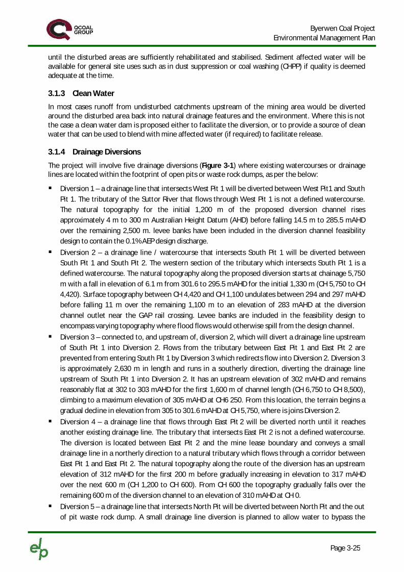
3.1.4 Drainage Diversions
The project will involve five drainage diversions (Figure 3-1) where existing watercourses or drainage lines are located within the footprint of open pits or waste rock dumps, as per the below:
Diversion 1 – a drainage line that intersects West Pit 1 will be diverted between West Pit1 and South Pit 1. The tributary of the Suttor River that flows through West Pit 1 is not a defined watercourse. The natural topography for the initial 1,200 m of the proposed diversion channel rises approximately 4 m to 300 m Australian Height Datum (AHD) before falling 14.5 m to 285.5 mAHD over the remaining 2,500 m. levee banks have been included in the diversion channel feasibility design to contain the 0.1% AEP design discharge.
Diversion 2 – a drainage line / watercourse that intersects South Pit 1 will be diverted between South Pit 1 and South Pit 2. The western section of the tributary which intersects South Pit 1 is a defined watercourse. The natural topography along the proposed diversion starts at chainage 5,750 m with a fall in elevation of 6.1 m from 301.6 to 295.5 mAHD for the initial 1,330 m (CH 5,750 to CH 4,420). Surface topography between CH 4,420 and CH 1,100 undulates between 294 and 297 mAHD before falling 11 m over the remaining 1,100 m to an elevation of 283 mAHD at the diversion channel outlet near the GAP rail crossing. Levee banks are included in the feasibility design to encompass varying topography where flood flows would otherwise spill from the design channel.
Diversion 3 – connected to, and upstream of, diversion 2, which will divert a drainage line upstream of South Pit 1 into Diversion 2. Flows from the tributary between East Pit 1 and East Pit 2 are prevented from entering South Pit 1 by Diversion 3 which redirects flow into Diversion 2. Diversion 3 is approximately 2,630 m in length and runs in a southerly direction, diverting the drainage line upstream of South Pit 1 into Diversion 2. It has an upstream elevation of 302 mAHD and remains reasonably flat at 302 to 303 mAHD for the first 1,600 m of channel length (CH 6,750 to CH 8,500), climbing to a maximum elevation of 305 mAHD at CH6 250. From this location, the terrain begins a gradual decline in elevation from 305 to 301.6 mAHD at CH 5,750, where is joins Diversion 2.
Diversion 4 – a drainage line that flows through East Pit 2 will be diverted north until it reaches another existing drainage line. The tributary that intersects East Pit 2 is not a defined watercourse. The diversion is located between East Pit 2 and the mine lease boundary and conveys a small drainage line in a northerly direction to a natural tributary which flows through a corridor between East Pit 1 and East Pit 2. The natural topography along the route of the diversion has an upstream elevation of 312 mAHD for the first 200 m before gradually increasing in elevation to 317 mAHD over the next 600 m (CH 1,200 to CH 600). From CH 600 the topography gradually falls over the remaining 600 m of the diversion channel to an elevation of 310 mAHD at CH 0.
Diversion 5 – a drainage line that intersects North Pit will be diverted between North Pit and the out of pit waste rock dump. A small drainage line diversion is planned to allow water to bypass the

Byerwen Coal Project Environmental Management Plan
Page 3-26
North Pit and flow to Kangaroo Creek. This drainage diversion will be in place before mining operations commence at the North Pit. The drainage diversion put in place will remain as a permanent structure to divert water around the North Pit and its final void.

Wollo
mbi R
oad
Collinsville-Elphinstone Road
Bowen Develop
mental R
oad
North Pit
South Pit 2
East Pit 1
West Pit 3
West Pit 2
West Pit 1
South Pit 1East Pit 2
SUTTOR RIVE
R
SUTT
ORRI
VER
NorthernMIA/CHPP
Co-disposalDam
Co-disposalDam
SouthernMIA/CHPP
580000 590000 60000076
4000
0
7640
000
7650
000
7650
000
7660
000
7660
000
!
!
!
!
Queensland
CAIRNS
BRISBANE
TOWNSVILLE
ROCKHAMPTON
0 1 2 3 4 5Kilometres (A4)
© State of Queensland (Department of Environment and Resource Management (DERM), Department of Natural Resources and Mines (DNRM)). ELP has produced this map for the purpose of presenting a summary of relevant spatial information based on or containing data provided by the State of Queensland(DERM, DNRM) [2012] and other sources at the time the map was prepared. In consideration of the State permitting use of this data you acknowledge and agree that both the State and ELP give no warranty in relation to the data (including accuracy, reliability, completeness or suitability) and accept no liability(including without limitation, liability in negligence) for any loss, damage or costs (including consequential damage) relating to any use of or reliance upon the data. Data must not be used for direct marketing or be used in breach of privacy laws. Imagery outside of project area accurate +/- 100m.
±
G:\CLIENTS\A-TO-D\BYEGEN - Byerwen EIS Supplementary Report\GIS\Maps\EMP\BYEGEN_Fig3-1_diversions_140508.mxd
1:150,000Coordinate System: GDA 1994 MGA Zone 55
Diversions
Revision: R1
Author: Christopher.MaddoxDate: 8/05/2014
Byerwen CoalProject
Map Scale:
5
1
2 3
4
LegendProject AreaWaste Rock Dumps and PitsMine InfrastructureFormed Roads
Ç Existing Mine SiteDrainage LineDrainage BundDrainage Diversion
Figure 3-1

Byerwen Coal Project Environmental Management Plan
Page 3-28
3.2 Process Water, Water Demand and Water Supply Process water will be imported to site from an external supply source (SunWater’s Burdekin to Moranbah pipeline system) and reused on site where possible.
The process water circuit, of which the CHPP is part, is a closed system. Supernatant or decant water from the co-disposal facilities will be recycled to the process plants; however some water will be lost through evaporation, in coal processing or as part of the coal moisture content, and as such the make-up water will be from the external source. This provides a consistent and reliable water source and is therefore not included in the mine site water balance. The estimated average and maximum water demands for the project is summarised in Table 3-1. Water for potable water will be supplied by SunWater and treated to potable standard on site.
Table 3-1 Estimated Water Demand
Activity Demand (MLpa)
Average Maximum
Dust suppression 1,300 1,600
Vehicle washdown 70 70
Potable water 9 10
Northern CHPP raw water 1,000 3,400
Southern CHPP raw water 3,100 1,100
Total 5,479 6,180
3.3 Release Strategy It will be necessary for the project to release water to the environment to balance the mine water inventory. This will be achieved through a controlled release strategy that allows discharge into the environment when water quality and flow conditions are within acceptable limits. All releases for all waters would be made in accordance with a water management plan, specifying flow and quality criteria. See Section 6.3.3.
3.4 Water Management Infrastructure
3.4.1 Overview and Staging
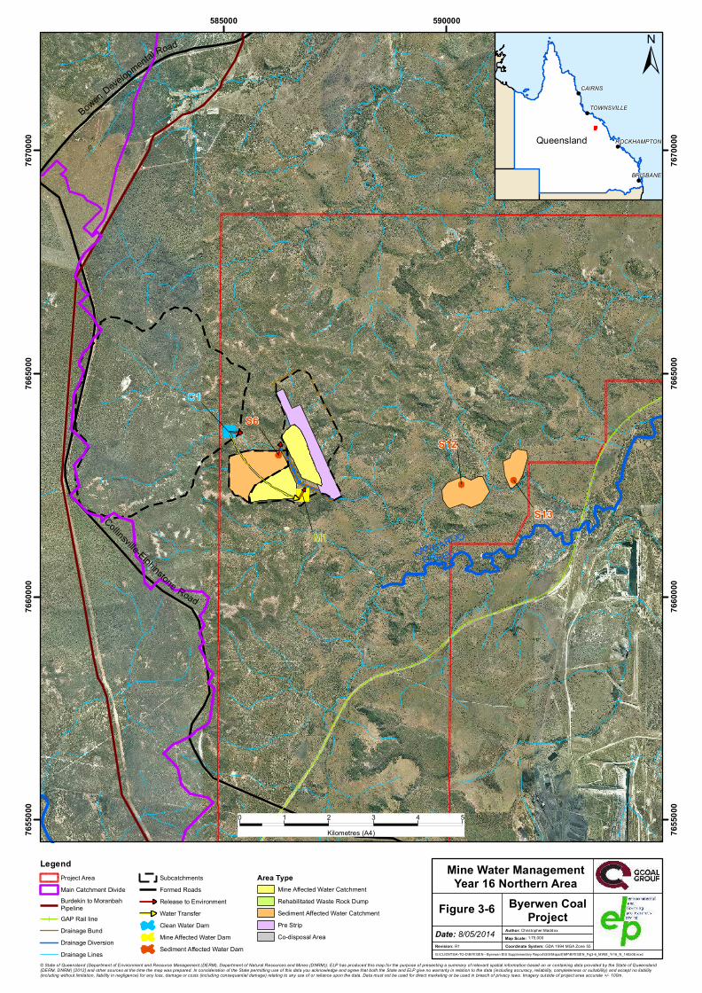
The mine water infrastructure requirements include six clean water dams, 23 mine affected water dams, 17 in-pit sumps and 27 sediment affected water dams. The conceptual layout of the dams (other than in-pit sumps) over various mine stages of mine life in the southern and northern areas is shown in Figure 3-2 to Figure 3-8. Certain dams will require progressive relocation in line with the progression of mining activities and the expansion of the pits; where this occurs the relocated dam has been allocated a discrete sequential identifying number. For example dam M4 is progressively relocated with the expansion of mining operations becoming dam, M5, M6 and ultimately dam M7. The figures present water management features in this south at years 3, 10, 25 and 46, and the north at years 16, 25 and 46.
Mine affected water dams are denoted with an ‘M’, clean water dams with a ‘C’ and sediment affected water dams with an ‘S’. Also shown on the figures are the catchment areas draining to the dams, the water transfer between dams and to the environment and the release points for water from dams. The

Byerwen Coal Project Environmental Management Plan
Page 3-29
indicative size of mine affected water dams and clean water dams is shown, but, sediment affected water dams are scaled for conceptual purposes only.

Wollo
mbi R
oad
Collin
svil le
-Elph
inston
eRoa
dSUTTORRIVER
M5
M9
M11
M16C4
C5
C6
C7
S2
S1
585000 590000 59500076
4000
0
7640
000
7645
000
7645
000
7650
000
7650
000
7655
000
7655
000
!
!
!
!
Queensland
CAIRNS
BRISBANE
TOWNSVILLE
ROCKHAMPTON
0 1 2 3 4 5Kilometres (A4)
© State of Queensland (Department of Environment and Resource Management (DERM), Department of Natural Resources and Mines (DNRM)). ELP has produced this map for the purpose of presenting a summary of relevant spatial information based on or containing data provided by the State of Queensland(DERM, DNRM) [2012] and other sources at the time the map was prepared. In consideration of the State permitting use of this data you acknowledge and agree that both the State and ELP give no warranty in relation to the data (including accuracy, reliability, completeness or suitability) and accept no liability(including without limitation, liability in negligence) for any loss, damage or costs (including consequential damage) relating to any use of or reliance upon the data. Data must not be used for direct marketing or be used in breach of privacy laws. Imagery outside of project area accurate +/- 100m.
±
G:\CLIENTS\A-TO-D\BYEGEN - Byerwen EIS Supplementary Report\GIS\Maps\EMP\BYEGEN_Fig3-2_MWM_Yr3_S_140508.mxd
1:75,000Coordinate System: GDA 1994 MGA Zone 55
Mine Water ManagementYear 3 Southern Area
Revision: R1
Author: Christopher.Maddox
Figure 3-2Date: 8/05/2014
Byerwen CoalProject
Map Scale:
LegendProject AreaMain Catchment DivideBurdekin to MoranbahPipelineGAP Rail lineDrainage BundDrainage DiversionDrainage Lines
SubcatchmentsClean Water DamMine Affected Water DamSediment Affected Water DamFormed RoadsRelease to EnvironmentWater Transfer
Area TypeMine Affected Water CatchmentRehabilitated Waste Rock DumpSediment Affected Water CatchmentPre StripCo-disposal Area

Wollo
mbi R
oad
Collin
svil le
-Elph
inston
eRoa
dSUTTORRIVER
S4S1
M7
M12
M17
M20
M15
C5
C6
C7
585000 590000 59500076
4000
0
7640
000
7645
000
7645
000
7650
000
7650
000
7655
000
7655
000
!
!
!
!
Queensland
CAIRNS
BRISBANE
TOWNSVILLE
ROCKHAMPTON
0 1 2 3 4 5Kilometres (A4)
© State of Queensland (Department of Environment and Resource Management (DERM), Department of Natural Resources and Mines (DNRM)). ELP has produced this map for the purpose of presenting a summary of relevant spatial information based on or containing data provided by the State of Queensland(DERM, DNRM) [2012] and other sources at the time the map was prepared. In consideration of the State permitting use of this data you acknowledge and agree that both the State and ELP give no warranty in relation to the data (including accuracy, reliability, completeness or suitability) and accept no liability(including without limitation, liability in negligence) for any loss, damage or costs (including consequential damage) relating to any use of or reliance upon the data. Data must not be used for direct marketing or be used in breach of privacy laws. Imagery outside of project area accurate +/- 100m.
±
\\192.168.51.223\elp_data\CLIENTS\A-TO-D\BYEGEN - Byerwen EIS Supplementary Report\GIS\Maps\EMP\BYEGEN_Fig3-3_MWM_Yr10_S_140512.mxd
1:75,000Coordinate System: GDA 1994 MGA Zone 55
Mine Water ManagementYear 10 Southern Area
Revision: R1
Author: Christopher.Maddox
Figure 3-3Date: 12/05/2014
Byerwen CoalProject
Map Scale:
LegendProject AreaMain Catchment DivideBurdekin to MoranbahPipelineGAP Rail lineDrainage BundDrainage DiversionDrainage Lines
SubcatchmentsFormed RoadsRelease to EnvironmentWater TransferClean Water DamMine Affected Water DamSediment Affected Water Dam
Area TypeMine Affected Water CatchmentRehabilitated Waste Rock DumpSediment Affected Water CatchmentPre StripCo-disposal Area

Collin
svil le
-Elph
inston
eRoa
dSUTTORRIVER
S8a/b
S9
S11
S10
S1
M8
M13
M18
M22
M23
M2
C5
C6
C3
C8
585000 590000 59500076
4000
0
7640
000
7645
000
7645
000
7650
000
7650
000
7655
000
7655
000
!
!
!
!
Queensland
CAIRNS
BRISBANE
TOWNSVILLE
ROCKHAMPTON
0 1 2 3 4 5Kilometres (A4)
© State of Queensland (Department of Environment and Resource Management (DERM), Department of Natural Resources and Mines (DNRM)). ELP has produced this map for the purpose of presenting a summary of relevant spatial information based on or containing data provided by the State of Queensland(DERM, DNRM) [2012] and other sources at the time the map was prepared. In consideration of the State permitting use of this data you acknowledge and agree that both the State and ELP give no warranty in relation to the data (including accuracy, reliability, completeness or suitability) and accept no liability(including without limitation, liability in negligence) for any loss, damage or costs (including consequential damage) relating to any use of or reliance upon the data. Data must not be used for direct marketing or be used in breach of privacy laws. Imagery outside of project area accurate +/- 100m.
±
G:\CLIENTS\A-TO-D\BYEGEN - Byerwen EIS Supplementary Report\GIS\Maps\EMP\BYEGEN_Fig3-4_MWM_Yr25_S_140512.mxd
1:75,000Coordinate System: GDA 1994 MGA Zone 55
Mine Water ManagementYear 25 Southern Area
Revision: R1
Author: Christopher.Maddox
Figure 3-4Date: 12/05/2014
Byerwen CoalProject
Map Scale:
LegendProject AreaMain Catchment DivideBurdekin to MoranbahPipelineGAP Rail lineDrainage BundDrainage DiversionDrainage Lines
SubcatchmentsFormed RoadsRelease to EnvironmentWater TransferClean Water DamMine Affected Water DamSediment Affected Water Dam
Area TypeMine Affected Water CatchmentRehabilitated Waste Rock DumpSediment Affected Water CatchmentPre StripCo-disposal Area

Wollo
mbi R
oad
Collin
svil le
-Elph
inston
eRoa
dSUTTORRIVER
S14a/b
S15a/b
S16a/b
S17S18
S20S19
S21a/b
S22S1
M3
M14
M21
C5
C3
C6
585000 590000 59500076
4000
0
7640
000
7645
000
7645
000
7650
000
7650
000
7655
000
7655
000
!
!
!
!
Queensland
CAIRNS
BRISBANE
TOWNSVILLE
ROCKHAMPTON
0 1 2 3 4 5Kilometres (A4)
© State of Queensland (Department of Environment and Resource Management (DERM), Department of Natural Resources and Mines (DNRM)). ELP has produced this map for the purpose of presenting a summary of relevant spatial information based on or containing data provided by the State of Queensland(DERM, DNRM) [2012] and other sources at the time the map was prepared. In consideration of the State permitting use of this data you acknowledge and agree that both the State and ELP give no warranty in relation to the data (including accuracy, reliability, completeness or suitability) and accept no liability(including without limitation, liability in negligence) for any loss, damage or costs (including consequential damage) relating to any use of or reliance upon the data. Data must not be used for direct marketing or be used in breach of privacy laws. Imagery outside of project area accurate +/- 100m.
±
G:\CLIENTS\A-TO-D\BYEGEN - Byerwen EIS Supplementary Report\GIS\Maps\EMP\BYEGEN_Fig3-5_MWM_Yr46_S_140512.mxd
1:75,000Coordinate System: GDA 1994 MGA Zone 55
Mine Water ManagementYear 46 Southern Area
Revision: R1
Author: Christopher.Maddox
Figure 3-5Date: 12/05/2014
Byerwen CoalProject
Map Scale:
LegendProject AreaMain Catchment DivideBurdekin to MoranbahPipelineGAP Rail lineDrainage BundDrainage DiversionDrainage Lines
SubcatchmentsFormed RoadsRelease to EnvironmentWater TransferClean Water DamMine Affected Water DamSediment Affected Water Dam
Area TypeMine Affected Water CatchmentRehabilitated Waste Rock DumpSediment Affected Water CatchmentPre StripCo-disposal Area
Collinsville-Elphinstone Road
BowenDevelopmental Road
KANG AROO
CREEK
S6S12
S13M1
C1
585000 59000076
5500
0
7655
000
7660
000
7660
000
7665
000
7665
000
7670
000
7670
000
!
!
!
!
Queensland
CAIRNS
BRISBANE
TOWNSVILLE
ROCKHAMPTON
0 1 2 3 4 5Kilometres (A4)
© State of Queensland (Department of Environment and Resource Management (DERM), Department of Natural Resources and Mines (DNRM)). ELP has produced this map for the purpose of presenting a summary of relevant spatial information based on or containing data provided by the State of Queensland(DERM, DNRM) [2012] and other sources at the time the map was prepared. In consideration of the State permitting use of this data you acknowledge and agree that both the State and ELP give no warranty in relation to the data (including accuracy, reliability, completeness or suitability) and accept no liability(including without limitation, liability in negligence) for any loss, damage or costs (including consequential damage) relating to any use of or reliance upon the data. Data must not be used for direct marketing or be used in breach of privacy laws. Imagery outside of project area accurate +/- 100m.
±
G:\CLIENTS\A-TO-D\BYEGEN - Byerwen EIS Supplementary Report\GIS\Maps\EMP\BYEGEN_Fig3-6_MWM_Yr16_N_140508.mxd
1:75,000Coordinate System: GDA 1994 MGA Zone 55
Mine Water ManagementYear 16 Northern Area
Revision: R1
Author: Christopher.Maddox
Figure 3-6Date: 8/05/2014
Byerwen CoalProject
Map Scale:
LegendProject AreaMain Catchment DivideBurdekin to MoranbahPipelineGAP Rail lineDrainage BundDrainage DiversionDrainage Lines
SubcatchmentsFormed RoadsRelease to EnvironmentWater TransferClean Water DamMine Affected Water DamSediment Affected Water Dam
Area TypeMine Affected Water CatchmentRehabilitated Waste Rock DumpSediment Affected Water CatchmentPre StripCo-disposal Area

Collinsville-Elphinstone Road
BowenDevelopmental Road
KANG AROO
CREEK
S6S12
S13
M1
C1
585000 59000076
5500
0
7655
000
7660
000
7660
000
7665
000
7665
000
7670
000
7670
000
!
!
!
!
Queensland
CAIRNS
BRISBANE
TOWNSVILLE
ROCKHAMPTON
0 1 2 3 4 5Kilometres (A4)
© State of Queensland (Department of Environment and Resource Management (DERM), Department of Natural Resources and Mines (DNRM)). ELP has produced this map for the purpose of presenting a summary of relevant spatial information based on or containing data provided by the State of Queensland(DERM, DNRM) [2012] and other sources at the time the map was prepared. In consideration of the State permitting use of this data you acknowledge and agree that both the State and ELP give no warranty in relation to the data (including accuracy, reliability, completeness or suitability) and accept no liability(including without limitation, liability in negligence) for any loss, damage or costs (including consequential damage) relating to any use of or reliance upon the data. Data must not be used for direct marketing or be used in breach of privacy laws. Imagery outside of project area accurate +/- 100m.
±
G:\CLIENTS\A-TO-D\BYEGEN - Byerwen EIS Supplementary Report\GIS\Maps\EMP\BYEGEN_Fig3-7_MWM_Yr25_N_140508.mxd
1:75,000Coordinate System: GDA 1994 MGA Zone 55
Mine Water ManagementYear 25 Northern Area
Revision: R1
Author: Christopher.Maddox
Figure 3-7Date: 8/05/2014
Byerwen CoalProject
Map Scale:
LegendProject AreaMain Catchment DivideBurdekin to MoranbahPipelineGAP Rail lineDrainage BundDrainage DiversionDrainage Lines
SubcatchmentsFormed RoadsRelease to EnvironmentWater TransferClean Water DamMine Affected Water DamSediment Affected Water Dam
Area TypeMine Affected Water CatchmentRehabilitated Waste Rock DumpSediment Affected Water CatchmentPre StripCo-disposal Area

C1
M1
S7 S12
S13Collinsville-Elphinstone Road
BowenDevelopmental Road
KANG AROO
CREEK
585000 59000076
5500
0
7655
000
7660
000
7660
000
7665
000
7665
000
7670
000
7670
000
!
!
!
!
Queensland
CAIRNS
BRISBANE
TOWNSVILLE
ROCKHAMPTON
0 1 2 3 4 5Kilometres (A4)
© State of Queensland (Department of Environment and Resource Management (DERM), Department of Natural Resources and Mines (DNRM)). ELP has produced this map for the purpose of presenting a summary of relevant spatial information based on or containing data provided by the State of Queensland(DERM, DNRM) [2012] and other sources at the time the map was prepared. In consideration of the State permitting use of this data you acknowledge and agree that both the State and ELP give no warranty in relation to the data (including accuracy, reliability, completeness or suitability) and accept no liability(including without limitation, liability in negligence) for any loss, damage or costs (including consequential damage) relating to any use of or reliance upon the data. Data must not be used for direct marketing or be used in breach of privacy laws. Imagery outside of project area accurate +/- 100m.
±
G:\CLIENTS\A-TO-D\BYEGEN - Byerwen EIS Supplementary Report\GIS\Maps\EMP\BYEGEN_Fig3-8_MWM_Yr46_N_140508.mxd
1:75,000Coordinate System: GDA 1994 MGA Zone 55
Mine Water ManagementYear 46 Northern Area
Revision: R1
Author: Christopher.Maddox
Figure 3-8Date: 8/05/2014
Byerwen CoalProject
Map Scale:
LegendProject AreaMain Catchment DivideBurdekin to MoranbahPipelineGAP Rail lineDrainage BundDrainage DiversionDrainage Lines
SubcatchmentsFormed RoadsRelease to EnvironmentWater TransferClean Water DamMine Affected Water DamSediment Affected Water Dam
Area TypeMine Affected Water CatchmentRehabilitated Waste Rock DumpSediment Affected Water CatchmentPre StripCo-disposal Area

Byerwen Coal Project Environmental Management Plan
Page 3-37
The majority of water transfer would be done through open channel or with the use of polypipe or layflat hose. Release to the environment would be accomplished using a combination of weirs, sluice gates and pumping to allow for all high and low capacity discharge occurrences. Smaller mixing dams will also be required at release points. These will allow controlled mixing of clean and dirty water before release. Mixing is predominately done during periods of recessional flow and therefore large amounts of mixing is not required and dam sizes would be small (i.e. <5 ML).
Release points of mine affected water dams will be on drainage lines to minimise the risk of scour with the exception of M2, M3 and M8. Scour protection may be required at the latter’s release point.
3.4.2 Dam Design and Sizing
3.4.2.1 Mine Affected Water Dams
The proposed water management system for mine affected catchments has been designed such that there are no unplanned releases to the environment. This has been achieved by:
dams meeting the DSA criteria as per the Manual for Assessing Hazard Categories and Hydraulic Performance of Dams (DERM, 2012), with a 5% or less probability that pits will be required to hold water
viable contingency measures that may be used for extreme climate scenarios.
The DSA is the minimum storage allowance provided by a dam for the wet season. The adopted design criteria meets the standards required for the corresponding hazard rating of the containment structures (refer Section 3.4.3). Consideration was also given to the fact that the project will operate several open cut mining pits for the majority of the mine life, providing an opportunity for emergency storage in one pit while still being able to maintain mining operations in the remaining pits.
3.4.2.2 Sediment Affected Water Dams
Sediment dams were designed based on containment of a 10 year ARI 24 hour design storm event.
3.4.2.3 Clean Water Dams
Clean water dams serve two purposes, to protect the mining areas from catchment runoff and to provide a clean water supply for use in dilution to achieve end-of-pipe and downstream water quality objectives.
Dams protecting the mining areas from catchment runoff are designed to have a very low risk of exceeding capacity, as the consequence of overtopping may result in flooding of the pit. Preliminary sizing is based on a 1% AEP and considers pipe and pump out capacity, with a balance between storage volume and pump capacity. However this will be further analysed during detailed design.
Clean water dams providing a clean water supply have been sized based on the reliability of supply to meet site requirements. Preliminary designs ensure natural catchment flows will continue.
3.4.2.4 Dam Sizing
Mine water infrastructure requirements satisfy the design criteria of the DSA (DERM, 2012) and meet the acceptable level of risk of utilising an emergency contingency measure. Mine affected water and clean water dams are proposed as ‘turkey’s nest’ type dams with the exception of C3 which is proposed as a valley dam with stage storage relationship has been extracted from survey data. The preliminary mine affected water and clean water dam capacities are provided in Table 3-2 and will be finalised during detailed design.
Sediment affected water dams range in size between 15 and 54 ML (approximately 1 ha per dam) while in-pit sumps range in size between 173 and 362 ML, other than the East Pits which are 29 to 37 ML.

Byerwen Coal Project Environmental Management Plan
Page 3-38
Table 3-2 Preliminary Mine Affected Water and Clean Water Dam Sizing
Dam Volume (ML) Height (m) Footprint (ha)
Mine Affected
M1 571 7.0 8.2
M2 475 7.0 6.8
M3 476 7.0 6.8
M4 183 7.0 2.6
M5 183 7.0 2.6
M6 183 7.0 2.6
M7 183 7.0 2.6
M8 137 7.0 2.0
M9 29 4.0 0.7
M10 29 4.0 0.7
M11 588 7.0 8.4
M12 588 7.0 8.4
M13 588 7.0 8.4
M14 588 7.0 8.4
M15 127 7.0 1.8
M16 392 7.0 5.6
M17 130 7.0 1.9
M18 130 7.0 1.9
M19 392 7.0 4.3
M20 392 7.0 4.3
M21 60 5.0 1.2
M22 484 7.0 6.9
M23 484 7.0 6.9
Clean Water
C1 100 7.0 7.1
C3 250 3.2 20.2
C4 469 7.0 6.7
C5 100 7.0 2.9
C6 651 7.0 9.3
C7 100 7.0 2.9
C8 150 7.0 2.1
3.4.3 Dam Hazard Assessment
The Manual sets out the requirements for hazard category assessment and certification of the design of ‘regulated structures’. A dam hazard assessment was conducted for all mine affected water dams, co-disposal dams, sediment affected water dams and clean water dams. All clean water dams and sediment affected water dams were classified as low hazard and are therefore not regulated dams. Table 3-3 provides a preliminary summary of the dam hazard assessment for mine affected water dams and the north and south co-disposal dams.
The DSA for the site requires containment of the 1% and 5% AEP for high and significant hazard rating respectively. This was used to determine the DSA with a safety factor or design simulation margin (DSM)

Byerwen Coal Project Environmental Management Plan
Page 3-39
of 50% in accordance with the Manual. Structures requiring a DSA will be brought down to this level by the 1 November each year in preparedness for the upcoming wet season. Regulated structures will be subject to the normal obligations for regulated structures, as shown below:
submission of detailed designs and documentation by a person suitably qualified and experienced in dam engineering (RPEQ)1
annual inspections by a person suitably qualified and experienced in dam engineering (RPEQ) design of a spillway to cater for a specific ARI based on the hazard category assigned to the dams inclusion of a suitable DSA and Mandatory Reporting Limits (MRL) assessment of the potential impacts of any failure of the dam embankments.
Table 3-3 Preliminary Dam Hazard Assessment
Dam Volume (ML)
Failure to contain scenario
Dam break scenario
Containment scenario
Hazard category
Regulated structure?
M1 571 Significant Significant Significant Significant Regulated
M2 475 Significant Significant Significant Significant Regulated
M3 476 Significant Significant Significant Significant Regulated
M4 183 Significant Significant Significant Significant Regulated
M5 183 Significant Significant Significant Significant Regulated
M6 183 Significant Significant Significant Significant Regulated
M7 183 Significant Significant Significant Significant Regulated
M8 137 Significant Significant Significant Significant Regulated
M9 29 Significant Low Significant Significant Regulated
M10 29 Significant Low Significant Significant Regulated
M11 588 Significant High Significant High Regulated
M12 588 Significant High Significant High Regulated
M13 588 Significant High Significant High Regulated
M14 588 Significant High Significant High Regulated
M15 127 Significant Low Significant Significant Regulated
M16 392 Significant Low Significant Significant Regulated
M17 130 Significant Significant Significant Significant Regulated
M18 130 Significant Significant Significant Significant Regulated
M19 392 Significant Significant Significant Significant Regulated
M20 392 Significant Significant Significant Significant Regulated
M21 60 Significant Low Significant Significant Regulated
M22 484 Significant Significant Significant Significant Regulated
M23 484 Significant Significant Significant Significant Regulated
1 See definition provided in Section 19

Byerwen Coal Project Environmental Management Plan
Page 3-40
Dam Volume (ML)
Failure to contain scenario
Dam break scenario
Containment scenario
Hazard category
Regulated structure?
South Co-disposal
10 000 High High Significant High Regulated
North Co-disposal
900 High High Significant High Regulated
Potential evaporative contaminant increases in mine affected water dams will be mitigated by regular releases of mine affected water in accordance with the release criteria and direct rainfall.
3.4.3.1 Referable Dams
Under the Water Supply (Safety and Reliability) Act 2008 (Qld), dam assessments must include a Failure Impact Assessment in accordance with Guidelines for Failure Impact Assessment of Water Dams (DERM, June 2010), if the dam being considered meets certain design parameters. The southern co-disposal dam is the only dam within the project’s water management system that may be considered a referable dam. A Failure Impact Assessment will be completed by the proponent, if required, when detailed designs of the southern co-disposal dam are available.
3.4.4 Design of Diversions
3.4.4.1 Conceptual Design and Construction Basis
The project diversion channel designs are based on the DEHP guideline on Watercourse Diversions – Central Queensland Mining Industry (DERM, 20112), which provides advice on stream powers, velocities and shear stresses that are considered to be the upper range for natural Bowen Basin watercourses. The Manual also outlines hydrological design criteria for regulated structures including levees and specifies that the crest level for levee embankments should contain a 0.1% AEP with 0.5 m additional freeboard.
The design objective for diversions is to establish new waterways that appear and function as natural features in the landscape largely indistinguishable from the pre-existing natural waterways. The intent is that new channels should reach an equilibrium state as soon as possible. 'Watercourse Diversions - Central Queensland Mining Industry' (DNRW 2008) was used as the basis for conceptual design of the diversions. The adopted design principles include:
Diversions will achieve long-term geomorphic stability as soon as possible. The diversions for the Project have adopted a channel bank batter slope of 1:5 (v:h). This design was adopted as a preliminary assumption based on limited geotechnical information, with the intention of refining these channel bank batter slopes as the design process progresses.
Diversion bed grade will be similar to that of the natural waterways, which will be achieved by designing sufficient length and cross-sectional area and incorporating meanders of adequate geometry where appropriate.
Diversions are to mimic pre-development natural channel form and hydraulic characteristics. Diversions will be constructed in advance to allow vegetation to establish prior to use. Hydraulic characteristics are to fall within commonly accepted thresholds for velocity, bed shear and
stream power.
2 Department of Environment and Resource Management (2011), Watercourse Diversions – Central Queensland Mining Industry, Central West Region, Queensland

Byerwen Coal Project Environmental Management Plan
Page 3-41
Competent rock armour materials will be selected where necessary for channel construction, catering for both high and low flow conditions.
The design of the diversions is expected to result in hydraulically stable channels. However, the planning, detailed design and construction sequence of the diversions are critical to ensure the new channel meets the design objectives. While these specific details will be developed during the detailed design phase, the overarching principles to be adopted during construction are:
Fill material: The diversions will be constructed using a cut/fill balance wherever possible. Geotechnical testing of soils will be required to ensure that the material proposed for use satisfies stability and permeability criteria when tested to Australian Standards.
Compaction: The levels of compaction specified for the diversion will be compacted to a minimum 95% Standard Maximum Dry Density. Consideration will need to be given to the effect of compaction on vegetation establishment. In areas where compaction may hinder vegetation establishment ripping may be used to promote plant growth.
Settlement: The diversions are intended to be constructed on natural ground therefore no settlement is envisaged. However, there may be some influence of adjacent excavations and fill activity. Surveys of the channel bed and cross-sections will be undertaken to ensure differential settlement does not initiate major erosion response within the project area. Any differential settlement that is identified will be repaired as required.
The creeks traversing the site are highly ephemeral with a clearly defined wet and dry season. Therefore construction of diversions will be preferentially undertaken during the dry season, where practicable. This will provide the best opportunity for juvenile vegetation to be established prior to being subjected to high flow conditions or prolonged periods of inundation.
The establishment of riparian vegetation will be critical in creating and maintaining the stability of proposed diversions as well as providing habitat. Assessment of existing riparian vegetation will be undertaken as part of the detailed design phase to provide a basis for developing the detailed revegetation plan. Revegetation species will consist of predominantly ground cover and small shrubs endemic to the area. The need for importation of topsoil for the purposes of establishing vegetation will be assessed during the detailed design phase.
During and upon immediate completion of earthworks the exposed surfaces of the diversion and levees may be highly susceptible to erosion which could result in sediment mobilisation or even structural failure. During the detailed design phase of the project, erosion and sediment control plans for construction will be developed. To limit the effects of erosion, construction should occur in stages with suitable erosion protection measures and sediment capture devices.
3.4.4.2 Design of Diversion 2
A Department of Natural Resources and Mines (DNRM) letter of advice (19 July 2012), advised that within the project boundary, two watercourses met the watercourse criteria of the Water Act 2000, one in Rosella Creek sub-catchment and one in Upper Suttor River sub-catchment. The watercourse within the Rosella Creek sub-catchment will not be diverted as a result of the project.
The watercourse within the Upper Suttor River sub-catchment is located at the downstream end of Tributary 1 (refer Figure 6-5), and is deemed to commence approximately 5,400 m upstream of the confluence with the Suttor River. Only the upper 2,000 m of the watercourse will be affected by the proposed diversion (Diversion 2 as shown in Figure 3-1). Drainage features that feed the watercourse will also be diverted. An application for this watercourse diversion will be made under the Water Act 2000, as further discussed in Section 6.5.

Byerwen Coal Project Environmental Management Plan
Page 3-42
The drainage corridor in which the proposed Diversion 2 will be constructed has been selected based on the following considerations:
existing geomorphological characteristics replicating existing meander radius (where possible) to maintain original stream length and gradient
to prevent bed aggradation and increase to sediment supply downstream buffer zone for riparian ecosystem Flood containment and limiting scour. no use of hydraulic control structures (e.g. drop structures) within the diversion or any other
structure that would require maintenance after relinquishment of the mine lease compliance with DERM (2011) hydraulic design criteria for stream power, shear stress and velocity
to maintain sediment transport equilibrium
The corridor selected allows for a similar creek length and grade as presented in Table 3-4. The large corridor width of 355 m allows a similar meander radius (150 m) to be used for the diversion.
Table 3-4 Diversion Characteristic Comparison
Characteristic Tributary 1 Diversion
Total Length (m) 8,200 8,500
Average Grade (%) 0.20 0.22
The natural drainage line (that feeds Tributary 1) intersects South Pit 1 and would be diverted to the south and separate South Pit 1 and South Pit 2. The diversion would start 300 m upstream of Wollombi Road, directing water south for 2,500 m before heading east between South Pit 1 and South Pit 2 eventually turning north (after 5,000 m) and discharging into Tributary 1 just upstream of the NML railway. The total length of the diversion channel is 8,500 m.
Levee banks have been included in the diversion channel feasibility design to encompass this varying topography.
The width of the diversion corridor would be 355 m to accommodate for meanders and a minimum allowance of 30 m on either side of the levees or from top of bank to allow for design modifications and future possible erosion.
The proposed diversion channel will require part of the Wollombi Road to be removed. The existing road crossing of the tributary has limited flood immunity. A causeway can be constructed to reconnect the road with flood immunity similar to the existing crossing, or it may be increased as required by the mine by raising the road above the bottom of the diversion channel using culverts for cross drainage.
The channel design has been progressed to a preliminary concept level to demonstrate that the proposed alignment, corridor width and channel form can feasibly meet the design objectives. The design will be reviewed and refined at the detail design stage. The concept diversion channel has a minimum depth of 4.4 m and minimum top width of 64 m with a 1:5 bank slope, to give a bottom width of 20 m. This caters for flows up to and including the 1,000 year ARI event with a minimum freeboard of 0.5 m. It is recommended that a low flow channel is incorporated into the design to replicate the existing watercourse conditions and allow pool/riffle zones to operate. Table 3.3 summarises the details of the proposed diversion.

Byerwen Coal Project Environmental Management Plan
Page 3-43
Table 3-5 Summary Details of Diversion 2
Detail Diversion Minimum depth (m) 4.4 Minimum top width (m) 64 Bottom width (m) 20 Corridor length (m) 8,500 Corridor width (m)# 355 Deepest cut (m) 9 Highest levee bank (m) 2 Grade (%) 0.22 Bank slope 1:5 Channel bed roughness 0.045 Channel bank roughness 0.070 # Includes allowance for any meanders and levees
The hydraulic characteristics of Diversion 2 for the maximum stream power, velocity and shear stress in the diversion channel were assessed against the DERM guidelines (2011). The values of the hydraulic parameters in the diversion channel are all within the guideline values.
3.4.4.3 Design of Diversions 1, 3, 4 and 5
Table 3-6 summarises the diversion design parameters for Diversion 1, 3 and 4. A small diversion (Diversion 5) is planned to bypass the North Pit and flow to Kangaroo Creek; however this is not required until later in the mine life (approximately Year 15) and will be designed once further detailed surveys have been completed.
Table 3-6 Summary Details of Diversions
Detail Diversion 1 Diversion 3 Diversion 4
Minimum depth (m) 3.6 4.4 2.4
Minimum top width (m) 56 64 40
Bottom width (m) 20 20 20
Corridor length (m) 3,700 2,580 1,700
Corridor width (m)1 215 355 130
Deepest cut (m) 7 7.5 6.5
Highest levee bank (m) 1.5 2 2
Grade (%) 0.30 0.23 0.20
Bank slope 1:5 1:5 1:5
Note 1: Includes allowance for any meanders and levees
3.4.5 Diversion Monitoring
Baseline monitoring of diversions, outlined in Table 3-7, will be conducted for a minimum of 12 months prior to construction.

Byerwen Coal Project Environmental Management Plan
Page 3-44
Table 3-7 Baseline Monitoring Requirements
Actions Purpose
Index of Diversion Condition (IDC)
The IDC method will be undertaken along the reach to be diverted as well as at the control reach (upstream reach). Photographs will be taken to record the condition of the stream before works are initiated. Photographs will be taken at the control reach, the reach to be diverted and the downstream reach. Photographs will be taken from fixed points along the control and diversion reaches to allow future comparisons.
Aerial Photographs
Aerial photos displaying the existing condition of the creeks and also the location of the new diversion will be taken before works begin. The scale of the aerial photo should be sufficient to allow accurate measurements of the diversion and adjoining river or stream.
Survey A cross section survey and long section survey of the stream or river upstream (control reach) and downstream (downstream reach) of the proposed diversion will be conducted as part of diversion detailed design. This information will be useful during relinquishment monitoring to demonstrate the diversion has had no adverse impacts on upstream and downstream reaches.
Vegetation The species, abundance and diversity of vegetation in the reach to be diverted will be recorded prior to diversion detailed design and construction. This information will also be used as part of the revegetation of the new diversion and used for comparison during relinquishment monitoring.
Flow Events In the absence of flow data, information regarding the site and frequency of flow events will be approximated by validation of debris marks against hydraulic modelling undertaken.
3.5 Proposed EA Conditions
Schedule J – Dams and levees
Consequence category J1 The consequence category of any structure must be assessed by a suitably qualified and
experienced person in accordance with the Manual for Assessing Consequence Categories and Hydraulic Performance of Structures (EM635) at the following times:
a) prior to the design and construction of the structure; and b) prior to any change in its purpose or the nature of its stored contents.
J2 A consequence assessment report and certification must be prepared for each structure assessed and the report may include a consequence assessment for more than one structure.
J3 Certification must be provided by the suitably qualified and experienced person who undertook the assessment, in the form set out in the Manual for Assessing Consequence Categories and Hydraulic Performance of Structures (EM635)
Design and construction of a regulated structure
J4 All regulated structures must be designed by, and constructed under the supervision of, a suitably qualified and experienced person in accordance with the requirements of the Manual for Assessing Consequence Categories and Hydraulic Performance of Structures (EM635).