2.+4.+6. a123 – mft–h–2/eng oem operating ... description mft-h / technical data set on off...
TRANSCRIPT

OEM
❏ NEW
❏ supplement to ..............
..............
.....
❏ replaces 2.A123-990201-ENG
✗
2.+4.+6. A123 – MFT–H–2/ENGOperating Instructions MFT-H Handy for MFT/MFT2 actuators
2
Notes/Power supply
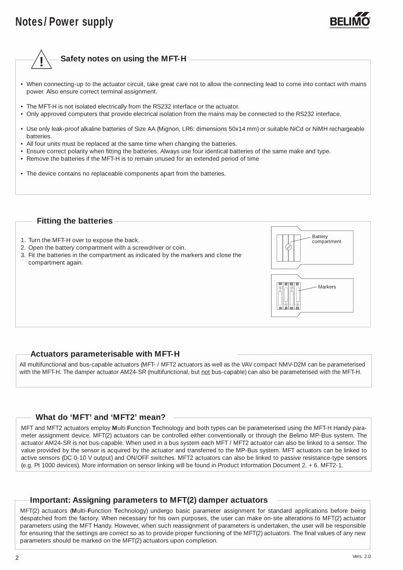
• When connecting-up to the actuator circuit, take great care not to allow the connecting lead to come into contact with mainspower. Also ensure correct terminal assignment.
• The MFT-H is not isolated electrically from the RS232 interface or the actuator. • Only approved computers that provide electrical isolation from the mains may be connected to the RS232 interface.
• Use only leak-proof alkaline batteries of Size AA (Mignon, LR6: dimensions 50x14 mm) or suitable NiCd or NiMH rechargeablebatteries.
• All four units must be replaced at the same time when changing the batteries. • Ensure correct polarity when fitting the batteries. Always use four identical batteries of the same make and type.• Remove the batteries if the MFT-H is to remain unused for an extended period of time
• The device contains no replaceable components apart from the batteries.
Safety notes on using the MFT-H
MFT(2) actuators (Multi-Function Technology) undergo basic parameter assignment for standard applications before beingdespatched from the factory. When necessary for his own purposes, the user can make on-site alterations to MFT(2) actuatorparameters using the MFT Handy. However, when such reassignment of parameters is undertaken, the user will be responsiblefor ensuring that the settings are correct so as to provide proper functioning of the MFT(2) actuators. The final values of any newparameters should be marked on the MFT(2) actuators upon completion.
Important: Assigning parameters to MFT(2) damper actuators
MFT and MFT2 actuators employ Multi Function Technology and both types can be parameterised using the MFT-H Handy para-meter assignment device. MFT(2) actuators can be controlled either conventionally or through the Belimo MP-Bus system. Theactuator AM24-SR is not bus-capable. When used in a bus system each MFT / MFT2 actuator can also be linked to a sensor. Thevalue provided by the sensor is acquired by the actuator and transferred to the MP-Bus system. MFT actuators can be linked toactive sensors (DC 0-10 V output) and ON/OFF switches. MFT2 actuators can also be linked to passive resistance-type sensors(e.g. Pt 1000 devices). More information on sensor linking will be found in Product Information Document 2. + 6. MFT2-1.
What do ‘MFT’ and ‘MFT2’ mean?
All multifunctional and bus-capable actuators (MFT- / MFT2 actuators as well as the VAV compact NMV-D2M can be parameterisedwith the MFT-H. The damper actuator AM24-SR (multifunctional, but not bus-capable) can also be parameterised with the MFT-H.
!
Actuators parameterisable with MFT-H
1. Turn the MFT-H over to expose the back.2. Open the battery compartment with a screwdriver or coin.3. Fit the batteries in the compartment as indicated by the markers and close the
compartment again.
Batterycompartment
Markers
Fitting the batteries
Vers. 2.0

Contents
3
Brief description MFT-H 4Technical data /Accessoires 4
Connection options / Wiring 5
Powering up/down, Fault alarms 6
Using the tree-menus 7
Tree menu: 8NM24-MFT(2)AM24-MFT(2), AM24-SRGM24-MFT(2)
Tree menu: 9LF24-MFT(2)AF24-MFT(2)
Tree menu: 10NV24-MFT(2)NVF24-MFT(2)NVF24-MFT(2)-E
Tree menu: 11NMV-DM2
Description of menu functionsActuator AA1 Default functions 12-13
A2 Modify / A2.1 Control 14
A2 Modify / A2.2 Feedback 15
A2 Modify / A2.3 Motion 16
A2 Modify / A2.4 Copy 17A2 Modify / A2.5 Reset 17
A3 Service 18
MFT-H settings E 19
MP - adressing 20
Example of parameter assignmentExample of an SRS function 21
AppendixInstructions for a Handy software upgrade 22-23
Vers. 2.0

Operating controls Action➀ ON/OFF switch and Press to toggle On and Off
display illumination Press for at least 2 s to illuminate display(MFT-H must be powered up first)
➁ ESC Escape Key Press briefly once to move back one level in the menuPress for at least 2 s to return to the main menu
➂ SET Memory Key Jump to selected menu Enter selected command
➃ Direction Keys For moving the cursor to the next line or the previousline of the menu. When there are up to 3 selected stepsper menu, the cursor will jump from line to line. Whenthere are more than 3 selected steps it will scroll one lineat a time each time a key is pressed. The longer the keysare held depressed the faster will be the scrolling. An audible signal is given when the last line of the menuis reached with the key pressed.
⑤ Direction Keys For selecting steps in the menus when there are severalside-by-side.
➅ LCD Display 4-line➆ RS232 connection Level converter PP or MP to RS232
Software upgrade MFT-H
➇ M Connection to MFT(2) actuator
4
Brief description MFT-H / Technical data
SET
ONOFF ESC
MFT-H
RS232
1
6
5
3
2
87
4
PPDC 24 V
M
• 1 Special adapter with compression terminals, type MFT-C • 1 Motor connecting lead, 2-pole with motor plug-connector and two 4 mm dia. plugs• 1 Power pack 24 V, type ZN230-24• 4 Mignon alkaline batteries • 2 Sheets of labels with 48 stickers on each (Item No. 31720)
incl. Waterproof felt-tip pen
Power supply 4 ordinary Mignon alkaline batteries 1.5 V, AA Size, LR6or rechargeable NiCd batteries can be used
Safety class (safety extra-low voltage)
Communications PP/MPDisplay LCD 4-line
Minimum An alarm appears on the display if the battery voltage voltage falls below 4.2 V
Maintenance Maintenance-free
Case ABS plastic (210 x 100 x 50 mm)
Weight 350 g
Accessories included MFT-H – SET
Connections• Power and PP/MP 3-pole motor plug-connector • RS232 D-Sub 9 pole / female
Technical data MFT-H
Optional (Not included in the MFT-H - SET)
Motor plug-connector, 3-pole for customised connecting lead, Item No. 11783
Ambient temperature range 0 °C...+50 °C
Parameter assignment by MFT-HMFT(2) actuators (Multi-Function Techno-logy) undergo basic parameter assignmentfor standard applications before being des-patched from the factory. When necessary,on-site alterations can be made to MFT(2)actuator parameters using the MFT-HParameter Assignment Device. The kind offunctions that can be set depends on thetype of MFT(2) actuator being used.
Checking service functions with theMFT-HThe MFT-H can be used for checking thefunctions of MFT(2) actuators. Either thevalues that have been previously assignedcan be read out or the actuator itself canbe operated with the MFT-H in order tocheck its functions.
Operating the MFT-HNo special knowledge of programming isneeded. The device is used interactivelyby means of its 4-line display and keypad.The procedure is based on the menumethod which guides the operator throughthe tree menu step-by-step. It almostcompletely eliminates any chance ofmaking mistakes. In the various menusand sub-menus the operator can definethe functions or parameters required.Implausible values will not be accepted bythe MFT-H.The language of communication to beused by the device can be preselected.
The MFT-H as level converterThe MFT-H can be used as a level con-verter between RS 232 and PP interfaces(ZIP function).
III
Operating controls
Tree menu (principle)
ONOFF
Actuator
Menu selection
AddressingMFT-Hsettings
Address
Defaultfunctions
Modify Service
Vers. 2.0

MP-Bus
T ~
AC 24 VDC 24 V
24 VMP
T~/+
LONWORKS
Connection options, Wiring
5
1 2 3 5
U MP
T ~
- +Y Z ...-MFT(2)
_ _ _ _ _ _ _ _ _ _ _ _ _ _ _
SET
ONOFF ESC
MFT-H
RS232 M
_ _ _ _ _ _ _ _ _ _ _ _ _ _ __ _ _ _ _ _ _ _ _ _ _ _ _ _ __ _ _ _ _ _ _ _ _ _ _ _ _ _ _
_ _ _ _ _ _ _ _ _ _ _ _ _ _ _
U5
Y
PPT
!Connect throughsafetytransformer- +
T
AC 24 VDC 24 V
~
Installer’s connectingterminals
Not included with MFT-H
1 2 3 5
T ~
- +Y Z ...-MFT(2)
_ _ _ _ _ _ _ _ _ _ _ _ _ _ _
SET
ONOFF ESC
MFT-H
RS232 M
_ _ _ _ _ _ _ _ _ _ _ _ _ _ __ _ _ _ _ _ _ _ _ _ _ _ _ _ __ _ _ _ _ _ _ _ _ _ _ _ _ _ _
_ _ _ _ _ _ _ _ _ _ _ _ _ _ _
+ DC 24 VPP
T
Transformeror 24 Vpower
~for DC 24V for AC 24V
Jackstereo / 3,5 mm dia. / 3-pole
for DC 24V for AC 24V
not assigned
1 2 5
DC 24 V
U MP
U PP
Special adapter MFT-C withcompression terminals an jack
Diagram 1Typical application:For assigning parameters to an MFT(2)actuator when it is already connectedinto the overall system.In this application the actuator is underanalogue control through the Y-signal.
Notes:• The MFT-H receives power from its
own batteries.• The MFT(2) actuator receives power
from the overall system.• The MFT(2) actuator is operable.• As long as the U/PP terminal of the
MFT(2) actuator is connected to the MFT-H, the feedback signal U5 will not correspond to the instantaneousactual value.
Diagram 2Typical application:For assigning parameters to an MFT(2)actuator before it is connected into theoverall system.Suitable as well for assigning the sameparameters to several MFT(2) actuators.
Notes:• The MFT-H receives power from its
own batteries.• The MFT(2) actuator receives power
from the MFT-H during parameter assignment.
• The MFT(2) actuator is only fully ope-rable when it is receiving an externalsupply of power via the jack.
• Providing an external supply of powerto the MFT(2) actuator via the specialadapter greatly extends the life of theMFT-H batteries.
UK24LON
MFT-H
MFT(2)-Actuators
1 2 3 4 5 6 7 8
Diagram 3Typical application:For assigning parameters to an MFT(2)actuator when it is connected togetherwith other actuators (up to a total of 8) viaan MP-Bus system to a UK24LON unit. Inthis application the MFT(2) actuators arecontrolled digitally over the MP-Bus.
Notes:• The MFT-H receives power from its
own batteries.• The MFT(2) actuators receive power via
the UK24LON unit.• Use the MFT-H to select MP addresses
1...8 in order to gain direct access tothe required actuator.
Vers. 2.0

6
Powering up/down, Fault alarms
Replacebatteries !
Communication and system fault alarms
Powering up/down
When an MFT-H Handy is powered up it is first initialised and the version of software with which it isloaded is displayed.
The subsequent behaviour of the Handy varies according to whether it is a first commissioning or arestart:
First power-up/First commissioning:When a Handy is powered up for the first time it jumps directly to the “Language” menu after initia-lising. This allows the appropriate language of use to be selected.
Restart:– on the same actuator:When the Handy is powered up again it jumps to the same menu item that it was at before it waspowered down, provided it is connected to the same actuator as before (i.e. the Serial No. andAddress correspond).
– on a different actuator:If a different actuator is connected to the Handy before it is powered up again the fault alarm “No actuator” appears on the display and an audible beep signal is given. If the actuator has alreadybeen addressed, enter the correct address under “Search” on the menu and the Handy will find theactuator in question. Otherwise it will first be necessary to assign an address to the actuator; see“Addressing”, Page ... .
Auto power-down:If, when a Handy is in use, none of its keys is pressed for a period of 5 minutes, it will power downautomatically.
Menu
Adressing
> ActuatorMFT settings
No actuator
Adressing
> Search...MFT-H settings
Any faults that occur are always identified by an alarm on the display and also by an audible beepsignal.
Alarms for exhausted batteriesWhen its batteries become exhausted (<4.2 V) the Handy generates an alarm on its display in theform of a flashing battery symbol. In order to avoid any loss of data the batteries must be replacedwithout delay.
If necessary, the alarm signal can be acknowledged with the key so that any parameterassignment task that has been started can be completed first. Although the status message willdisappear from the display the battery symbol will continue flashing. If the batteries are not replacedthe fault alarm will appear again as soon as the Handy is powered up again.
Fault alarms
BELIMO MFT-H
Initialising
Version 2.0
Language
Cancel
> DeutschEnglish
Vers. 2.0
SET
Message
No actuator
No reply from actuator
Defective transmission
Programming error
No EEPROM access
Command not recognised
Enter password: ....
Access denied
Possible causes of faults
Wiring error
MFT(2) actuator defective
MFT-H software version does not matchthat of the MFT(2) actuator
Input is password-protected
Belimo-barred input
Fault rectification
• Check wiring• Check address• Repeat command
Change MFT(2) actuator
Ascertain software versions ofMFT-H and MFT(2) actuator andconsult BelimoEnter password and start
Contact Belimo
Using the tree-menus
7
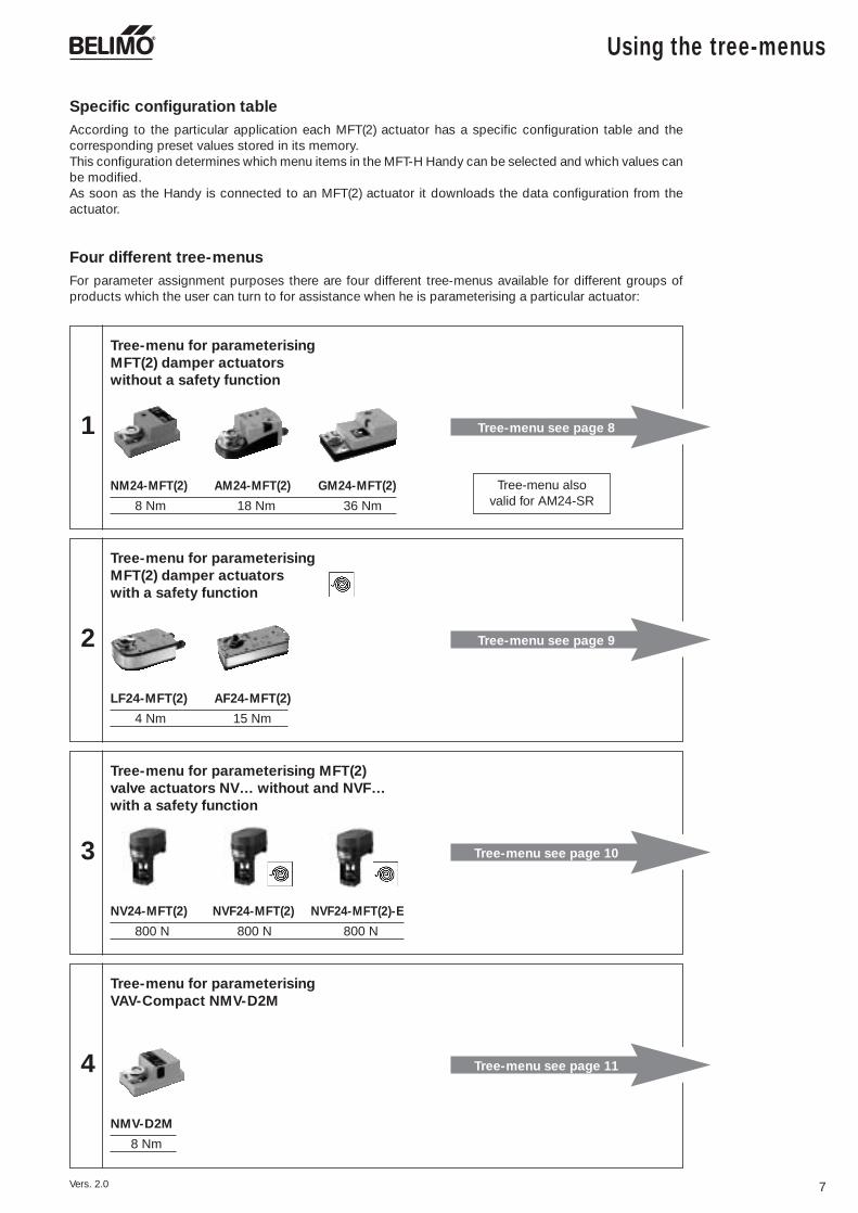
According to the particular application each MFT(2) actuator has a specific configuration table and thecorresponding preset values stored in its memory.This configuration determines which menu items in the MFT-H Handy can be selected and which values canbe modified.As soon as the Handy is connected to an MFT(2) actuator it downloads the data configuration from theactuator.
Specific configuration table
For parameter assignment purposes there are four different tree-menus available for different groups ofproducts which the user can turn to for assistance when he is parameterising a particular actuator:
Four different tree-menus
1
NM24-MFT(2) AM24-MFT(2) GM24-MFT(2)
8 Nm 18 Nm 36 Nm
Tree-menu for parameterising MFT(2) damper actuatorswithout a safety function
Tree-menu see page 8
2
LF24-MFT(2) AF24-MFT(2)
4 Nm 15 Nm
Tree-menu for parameterising MFT(2) damper actuatorswith a safety function
Tree-menu see page 9
3
NV24-MFT(2) NVF24-MFT(2) NVF24-MFT(2)-E
800 N 800 N 800 N
Tree-menu for parameterising MFT(2)valve actuators NV… without and NVF…with a safety function
Tree-menu see page 10
4
NMV-D2M
8 Nm
Tree-menu for parameterising VAV-Compact NMV-D2M
Tree-menu see page 11
Vers. 2.0
Tree-menu also valid for AM24-SR
Control
PW min PW max…… ……
Start Stop…… ……
Feedback
DC 2 – 10 V(Default)
DC 0 – 10 V
DCV variable
0.02 – 5s
0.59 – 2.93s
0.1 – 25.5s
PWM variable
DC 2 – 10 V(Default)
DC 0 – 10 V
DCV variable
Start Stop…… ……
Softswitch S
Open/Close
3-point
PWM control
DC control Voltage U
Stop/Go-Ratio
Mech. Overload
Alarms(S; W; –)
Alarms & U
Alarms & S
Motion
Torque
Copy
Enter original
copy
Reset
Last entry
All entries
Identification
Serial No.
Typ/SW version
Plant site ………
Reference/Actualvalue
Adapte
Function info
Data log
Alarms
Delete
Function test
Sensitivity
Normal(Default)
Reduced
Synchronisation
Normal
Sync. at 0%
Sync. at 100%
SR (DC 2…10 V)
3-point
Modify Service
Menu selection
PWM (0.59-2,93s)
Actuator
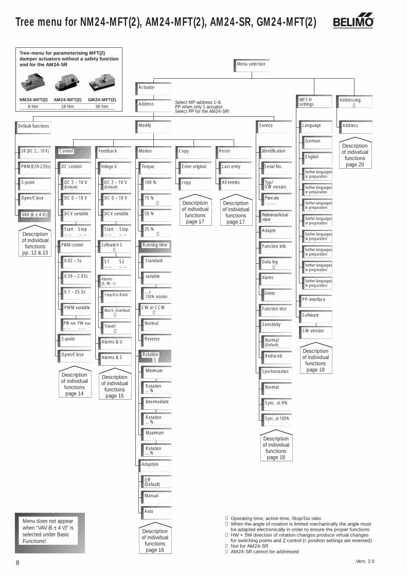
➀ Operating time, active time, Stop/Go ratio➁ When the angle of rotation is limited mechanically the angle must
be adapted electronically in order to ensure the proper functions➂ HW + SW direction of rotation changes produce virtual changes
for switching points and Z control (= position settings are reversed)➃ Not for AM24-SR➄ AM24-SR cannot be addressed
➁
➁
➀
Open/Close
S1 S2…… ……
Descriptionof individual
functionspage 15
Descriptionof individual
functionspage 14
Descriptionof individual
functionspp. 12 & 13
Descriptionof individual
functionspage 17
Descriptionof individual
functionspage 17
Descriptionof individual
functionspage 18
Default functions
Address
100 %
75 %
50 %
Running time
Normal
Reverse
Adaption
Off(Default)
Manual
Auto
➁
➂
Descriptionof individual
functionspage 16
CW or CCW
Rotation
25 %
Menu does not appearwhen “VAV (6 ± 4 V)” isselected under BasicFunctions!
Addressing
Address
Descriptionof individual
functionspage 20
➂
➁
MFT-Hsettings
Language
German
English
PP-interface
Software
SW-VersionSW version
further languagesin preparation
further languagesin preparation
further languagesin preparation
further languagesin preparation
further languagesin preparation
further languagesin preparation
further languagesin preparation
further languagesin preparation
Descriptionof individual
functionspage 19
Select MP-address 1–8.PP when only 1 actuator.Select PP for the AM24-SR!
Standard
variable
…s100% rotation
Minimum
Rotation…%
Intermediate
Rotation…%
Maximum
Rotation…%
Travel➁
VAV (6 ± 4 V)
➃
➃
➄
8
Tree menu for NM24-MFT(2), AM24-MFT(2), AM24-SR, GM24-MFT(2)
Vers. 2.0
NM24-MFT(2) AM24-MFT(2) GM24-MFT(2)
8 Nm 18 Nm 36 Nm
Tree-menu for parameterising MFT(2)damper actuators without a safety functionand for the AM24-SR

Tree menu for LF24-MFT(2), AF24-MFT(2)
9
Control
PW min PW max…… ……
Start Stop…… ……
Feedback
DC 2 – 10 V(Default)
DC 0 – 10 V
DCV variable
0.02 – 5s
0.59 – 2.93s
0.1 – 25.5s
PWM variable
DC 2 – 10 V(Default)
DC 0 – 10 V
DCV variable
Start Stop…… ……
Softswitch S
Open/Close
3-point
PWM control
DC control Voltage 0
Stop/Go-Ratio
Mech. Overload
Alarms(S; W; –)
Alarms & U
Alarms & S
Motion
Torque
Copy
Enter original
copy
Reset
Last entry
All entries
Identification
Serial No.
Typ/SW version
Plant site ………
Reference/Actualvalue
Adapte
Function-info
Data log
Alarms
Delete
Function test
Sensitivity
Normal(Default)
Reduced
Synchronisation
Normal
Sync. at 0%
Sync. at 100%
SR (DC 2…10 V)
3-point
Modify Service
Menu selection
PWM (0.59-2,93s)
Actuator
➀ Operating time, active time, Stop/Go ratio➁ When the angle of rotation is limited mechanically the angle must
be adapted electronically in order to ensure the proper functions➂ HW + SW direction of rotation changes produce virtual changes
for switching points and Z control (= position settings are reversed)
➁
➁
➀
Open/Close
S1 S2…… ……
Descriptionof individual
functionspage 15
Descriptionof individual
functionspage 14
Descriptionof individual
functionspp. 12 & 13
Descriptionof individual
functionspage 17
Descriptionof individual
functionspage 17
Descriptionof individual
functionspage 18
Default functions
Address
** Cannot be modified
** Cannot be modified. Spare menu item.
Running time
Normal
Reverse
Adaption
Off(Default)
Manual
Auto
➁
➂
Descriptionof individual
functionspage 16
CW or CCW
Rotation
Menu does not appearwhen “VAV (6 ± 4 V)” isselected under BasicFunctions!
Addressing
Address
Descriptionof individual
functionspage 20
➂
➁
MFT-Hsettings
Language
German
English
PP-interface
Software
SW-VersionSW version
further languagesin preparation
further languagesin preparation
further languagesin preparation
further languagesin preparation
further languagesin preparation
further languagesin preparation
further languagesin preparation
further languagesin preparation
Descriptionof individual
functionspage 19
Select MP-address 1–8.PP when only 1 actuator.
Standard
variable
…s100% rotation
Minimum
Rotation…%
Intermediate
Rotation…%
Maximum
Rotation…%
Travel➁
VAV (6 ± 4 V)
Vers. 2.0
LF24-MFT(2) AF24-MFT(2)
4 Nm 15 Nm
Tree-menu for parameterising MFT(2) damper actuatorswith a safety function

10
Tree menu for NV24-MFT(2), NVF24-MFT(2)(-E)
PW min PW max…… ……
Start Stop…… ……
Feedback
DC 2 – 10 V(Default)
DC 0 – 10 V
DCV variable
0.02 – 5s
0.59 – 2.93s
0.1 – 25.5s
PWM variable
DC 2 – 10 V(Default)
DC 0 – 10 V
DCV variable
Start Stop…… ……
Softswitch S
3-point
PWM control
DC control Voltage U
Alarms(S; W; –)
Motion
Force➁
Copy
Enter original
copy
Reset
Last entry
All entries
Identification
Serial No.
Typ/SW version
Plant site ………
Reference/Actualvalue
Adapte
Function info
Data log
Alarms
Delete
Function test
Sensitivity
Normal(Default)
Reduced
SR (DC 2…10 V)
3-point
Modify Service
Menu selection
PWM (0.59-2,93s)
Actuator
➀ Operating time, active time, Stop/Go ratio➁ With NVF... actuators the actuating force cannot be modified
(the appropriate menus do not appear).➂ HW + SW direction of rotation changes produce virtual changes
for switching points and Z control (= position settings are reversed)
➀S1 S2…… ……
Descriptionof individual
functionspage 14
Descriptionof individual
functionspp. 12 & 13
Descriptionof individual
functionspage 17
Descriptionof individual
functionspage 17
Descriptionof individual
functionspage 18
Default functions
Address
100 %
75 %
50 %
Normal
Reverse
➂
Descriptionof individual
functionspage 16
Direction of lift
25 %
Addressing
Address
Descriptionof individual
functionspage 20
➂
MFT-Hsettings
Language
German
English
PP-interface
Software
SW-VersionSW version
further languagesin preparation
further languagesin preparation
further languagesin preparation
further languagesin preparation
further languagesin preparation
further languagesin preparation
further languagesin preparation
further languagesin preparation
Descriptionof individual
functionspage 19
Select MP-address 1–8.PP when only 1 actuator.
Standard
variable
…s100% Range
Minimum
Valve stroke…%
Intermediate
Valve stroke…%
Maximum
Valve stroke…%
Control
Mech. Overload
Alarms & U
Alarms & S
Descriptionof individual
functionspage 15
Travel
Running time
Valve stroke
Vers. 2.0
NV24-MFT(2) NVF24-MFT(2) NVF24-MFT(2)-E
800 N 800 N 800 N
Tree-menu for parameterising MFT(2)valve actuators NV… without and NVF…with a safety function

Control
Start Stop…… ……
Feedback
DC 2 – 10 V(Default)
DC 0 – 10 V
DCV variable
DC 2 – 10 V(Default)
DC 0 – 10 V
DCV variable
Start Stop…… ……
DC control Voltage U
Motion
Torque
Copy
Enter original
copy
Reset
Last entry
All entries
Identification
Serial No.
Typ/SW version
Plant site ………
Reference/Actual value ➅
Adapte
Function info
Data log
Alarms
Delete
Function test
Sensitivity
Normal(Default)
Reduced
SR (DC 2…10 V)
Modify Service
Menu selection
Actuator
➀ Operating time, active time, Stop/Go ratio➁ When the angle of rotation is limited mechanically the angle must
be adapted electronically in order to ensure the proper functions➂ HW + SW direction of rotation changes produce virtual changes
for switching points and Z control (= position settings are reversed)➃ Settings for the electrical working range for volumetric flow.➄ Settings for the U5 voltage signal output for 0...100% nominal
volumetric flow.➅ Reference value and actual value as % of nominal volumetric flow.
Calculation of actual volumetric flow [m3/h]:VACT [m3/h] = VNOM- [m3/h] / 100 x VACT [%]
➆ The set value of running time has no effect on normal control.Settings are only active for override control.
➀
Descriptionof individual
functionspage 15
Descriptionof individual
functionspage 14
Descriptionof individual
functionspp. 12 & 13
Descriptionof individual
functionspage 17 Description
of individualfunctionspage 17
Descriptionof individual
functionspage 18
Default functions
Address
100 %
75 %
50 %
Running time
Normal
Reverse
Adaption
Off(Default)
Manual
Auto
➂
Descriptionof individual
functionspage 16
CW or CCW
25 %
Addressing
Address
Descriptionof individual
functionspage 20
➂
MFT-Hsettings
Language
German
English
PP-interface
Software
SW-VersionSW version
further languagesin preparation
further languagesin preparation
further languagesin preparation
further languagesin preparation
further languagesin preparation
further languagesin preparation
further languagesin preparation
further languagesin preparation
Descriptionof individual
functionspage 19
Select MP-address 1–8.PP when only 1 actuator.
Standard
Variable
…s100% Range
Minimum
Volumetric flow…%
Intermediate
Volumetric flow…%
Maximum
Volumetric flow…%
Control
Running time➆
Volumetric flow➁
Reset original
Tree menu for NMV-D2M (MFT)
11Vers. 2.0
NMV-D2M8 Nm
Tree-menu forparameterising VAV-Compact NMV-D2M

SET
SET
12
Menu functions, A1 Default functions
A1Default functions
SR (DC 2…10 V)
3-point
Open/Close
VAV (6 ± 4 V)
PWM (0.59-2.93s)
A1.1
A1.2
A1.3
A1.4
A1.5
A2
Modify Service
A3
E
Addressing
MPAddress
MP1
MFT-Hsetting
A
Menu selection
Actuator
Address Select MP-address 1–8.PP when only 1 actuator.
In the Default functions branch of thetree menu it is possible to assign so-called‘default’ or standard functions to MFT(2)actuators. For each default function a datarecord containing the normal standardparameters for the function is stored. Theappropriate function can be selected withthe direction keys. Pressing the
key enters the function into the actua-tor together with its data record. A warningappears on the display first which must beacknowledged by pressing the keyagain.
Vers. 2.0
A1.1 Default function SR (DC 2...10 V)Selecting this function parameterises theMFT(2) actuator for the modulating mode.
A1.2 Default function PWM (0.59-2.93s)Selecting this function parameterises theMFT(2) actuator for the PWM mode.
Explaining PWM control:PWM does not mean ‘pulse width modu-lation’ in its normal sense. The actuatormeasures the length of the control pulseand then moves to the correspondingposition. So far, PWM-type actuators areonly being used in the USA. Depending onthe type of actuator, the user can definevarious PWM ranges.
1 2 3
…-MFT..
5
U5
Y
T ~
AC 24 V- + DC 24 V
DC 0...10 VDC 2...10 V
U PP
T ~
- +Y Z
Default functions>SR(2-10V DC ) DisplayPWM(0.59-2.93s)3-point
Default functionsSR(2-10V DC ) Display
>PWM(0.59-2.93s)3-point
1 2 3
…-MFT..
5
U5
T ~
AC 24 V
DC 2...10 V
U PP
T ~
- +Y Z
t0,59-2,93 s
Wiring diagram SR Wiring diagram PWM
Examples of PWM control when a PWMrange of 0.59-2.93s has been selected forthe actuator:
Example 1, 100% angle of rotationWhen a pulse of 2.93s duration is sent tothe actuator it causes it to move to the100% angle-of-rotation position. (If thepulses sent to the actuator are of longerduration than 2.93 s the actuator will also move to the 100% angle-of-rotationposition).
Example 2, 50% angle of rotationWhen a pulse of 0.59s + (2.93s - 0.59s) / 2= 1.17s + 0.59 s duration is sent to theactuator it causes it to move to the 50%angle-of-rotation position.
Example 3, 0% angle of rotationWhen a pulse of 0.59 s duration is sent tothe actuator it causes it to move to the 0%angle-of-rotation position. (If the pulsessent to the actuator are of shorter durationthan 0.59s but longer duration than 20 msthe actuator will also move to the 0%angle-of-rotation position; at less than20 ms there is no defined function).
Data record PWM (0,59-2,93s) (Example AM24-MFT(2))Control signal Y PWMWorking range 0.59-2.93sFunctionFeedback U5 2...10 V DCTorque 18 Nm min.Angle of rotation 95ºRunning time 150 sAngle-of-rotationadaption none
Data record SR (DC 2...10 V) (Example AM24-MFT(2))Working range 2...10 V DC FunctionFeedback U5 2...10 V DC Torque 18 Nm min. Angle of rotation 95°Running time 150 sAngle of rotation adaption noneOverrides Min. (min. position) = 0%(referred to full angle IP (intermediate position) = 50%of rotation 95°) Max. (max. position) = 100%
Menu functions, A1 Default functions
13Vers. 2.0
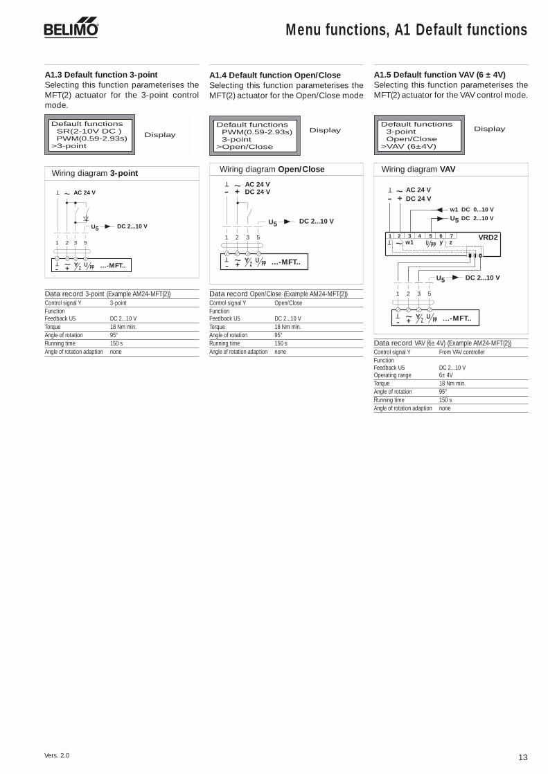
A1.3 Default function 3-pointSelecting this function parameterises theMFT(2) actuator for the 3-point controlmode.
U5
T ~
AC 24 V
1 2 3 5
U PP
T ~
+Y Z- …-MFT..
DC 2...10 V
Default functionsSR(2-10V DC ) DisplayPWM(0.59-2.93s)
>3-point
A1.4 Default function Open/CloseSelecting this function parameterises theMFT(2) actuator for the Open/Close mode
1 2 3
…-MFT..
5
U5
T ~
AC 24 V- + DC 24 V
DC 2...10 V
U PP
T ~
- +Y Z
Default functionsDisplayPWM(0.59-2.93s)
3-point>Open/Close
A1.5 Default function VAV (6 ± 4V)Selecting this function parameterises theMFT(2) actuator for the VAV control mode.
w1 DC 0...10 V
T1 2 3 4 5 7w1
6~
y zVRD2
U PP
DC 2...10 V
- +
T ~
AC 24 VDC 24 V
U5
1 2 3
…-MFT..
5
U PP
T ~
- +Y Z
U5 DC 2...10 V
Default functionsDisplay3-point
Open/Close>VAV (6±4V)
Wiring diagram 3-point Wiring diagram Open/Close Wiring diagram VAV
Data record 3-point (Example AM24-MFT(2))Control signal Y 3-point FunctionFeedback U5 DC 2...10 V Torque 18 Nm min. Angle of rotation 95°Running time 150 sAngle of rotation adaption none
Data record Open/Close (Example AM24-MFT(2))Control signal Y Open/Close FunctionFeedback U5 DC 2...10 V Torque 18 Nm min. Angle of rotation 95°Running time 150 sAngle of rotation adaption none
Data record VAV (6± 4V) (Example AM24-MFT(2))Control signal Y From VAV controller FunctionFeedback U5 DC 2...10 V Operating range 6± 4VTorque 18 Nm min. Angle of rotation 95°Running time 150 sAngle of rotation adaption none

Menu functions, A2 Modify
The Modify branch of the tree menu allowsthe values and functions of an MFT(2)actuator to be custom-parameterised whennecessary (see p. 21 Example of parameterassignment).
When the Modify branch of the menu is first entered it will always show the values andfunctions that were given to an MFT(2) actuator the last time it was assigned para-meters. If a modification of a particular default function (A1.x) only involves changing afew individual values from their default settings, it is advisable to load the MFT(2) actuatorwith the appropriate default function (see page 12) before making the modification.
SET
The mode of control required is selected with the direction keys and a variable working range with the direction keysand . Pressing the key either causes the menu to jump to the next sub-menu or the selected values are entered intothe actuator.
14 Vers. 2.0
A2Modify Service
MFT-Hsettings
Addressing
Default functions
Control
DC control
A2.1 Control allows appropriate working ranges to be defined for control modes
Feedback Motion Copy Reset
A1
A2.2 A2.3 A2.4
A3
E MP
A2.5
AActuator
Menu selection
Address
DC 2 – 10 V(Default)
A2.1.2 Selection of PWM control (MFT(2) actuator parameterised for PWM control)(see page 12, A1.2 Explaining PWM control)
PWmin PWmax…… ……
Start Stop…… ……
DC 0 – 10 V
DCV variable
0.02 – 5s
0.59 – 2.93s
0.1 – 25.5s
PWM variable
Open/Close
3-point
PWM control
A2.1.1a Selection of a fixed working range DC 2...10 V (as per SR (DC 2-10 V) see page 12, Section A1.1)
A2.1.1b Selection of a fixed working range DC 0.5...10 V
A2.1.1c Variable definition of a working range :
A2.1.2a Selection of a fixed PWM working range of 0.02...5s
A2.1.1d Variable definition of a PWM working range:
PWMmin. 0.02 s...... PWMmax. 50.00 s
A2.1.2b Selection of a fixed PWM working range of 0.59...2.93s
A2.1.2c Selection of a fixed PWM working range of 0.1...25.5
A2.1.3 Selection of 3-point control. MFT(2) actuator parameterised with data record for3-point actuator (see page 13, Section A1.3)
A2.1.4 Selection of Open/Close control. MFT(2) actuator parameterised with data record forOpen/Close actuator (see page 13, Section A1.4)
• Start DC 0.5...30.0 V; Finish DC 2.5...32.0 V• For the VAV-Compact NMV-D2M : Start point DC 0...30.0 V and Finish point DC 2.0...32.0 V Finish must be at least 2 V above Start!
A2.1.1 Selection of modulating control: The settings correspond to the electrical working range for 0...100% angleof rotation or stroke, in the case of VAV-Compact NMV-D2M = 0...100% nominal volumetric flow (VNOM)effect on working range if MAX and/or MIN positions (see Page 16, A2.3.4) are selected. The working rangecorresponds to the control range set with the MIN and MAX positions.The set MIN position corresponds to the Start point of the working range.The set MAX position corresponds to the Finish point of the working range.(For the VAV-Compact NMV-D2M the MIN position corresponds to the minimum volumetric flow VMIN andthe MAX position to the maximum volumetric flow VMAX)
A2.1 Control
Menu functions, A2 Modify
15
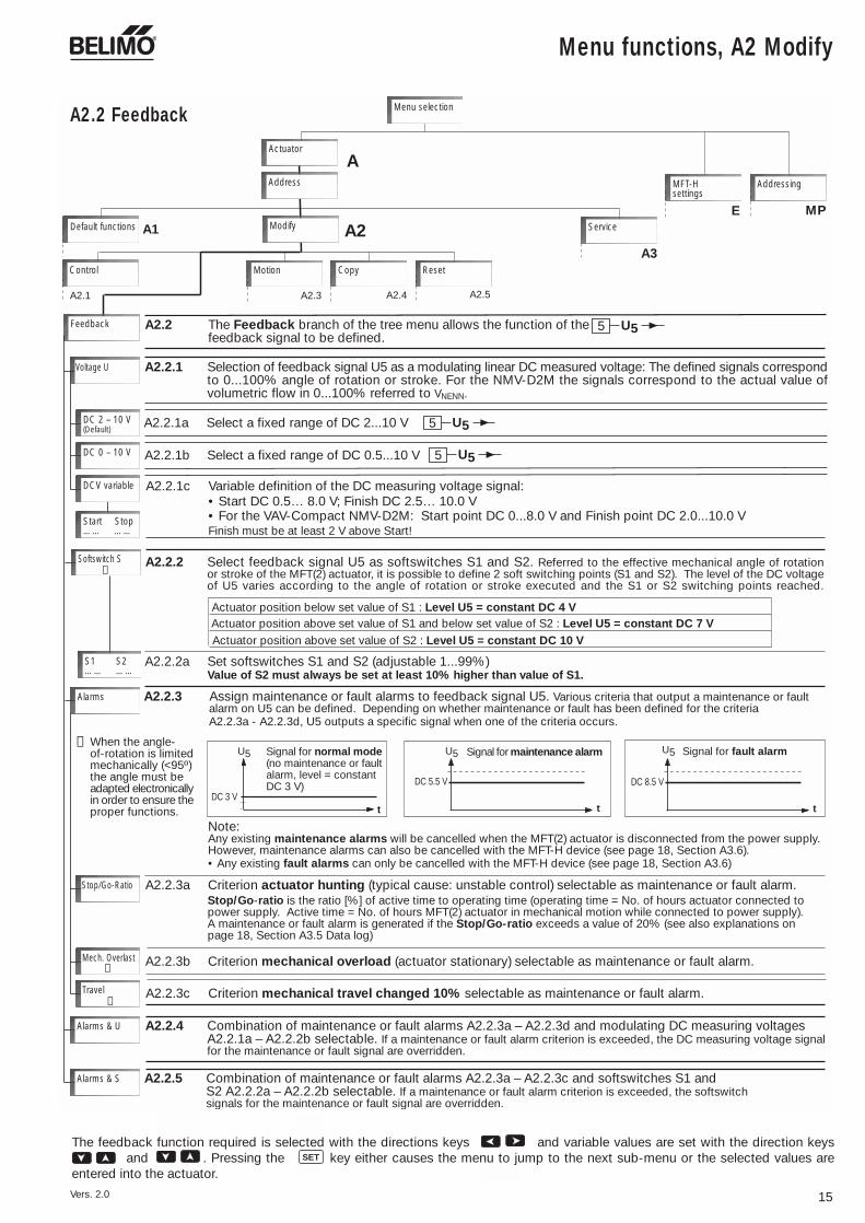
A2.2.1 Selection of feedback signal U5 as a modulating linear DC measured voltage: The defined signals correspondto 0...100% angle of rotation or stroke. For the NMV-D2M the signals correspond to the actual value ofvolumetric flow in 0...100% referred to VNENN.
A2
A
Modify Service
MFT-Hsettings
Addressing
Default functions
Address
Menu selection
Control
A2.2 The Feedback branch of the tree menu allows the function of the feedback signal to be defined.
Feedback
Motion Copy Reset
A1
A2.2.1a Select a fixed range of DC 2...10 V
A2.2.1b Select a fixed range of DC 0.5...10 V
A2.2.1c Variable definition of the DC measuring voltage signal:
A2.2.3a Criterion actuator hunting (typical cause: unstable control) selectable as maintenance or fault alarm.
A2.2.2a Set softswitches S1 and S2 (adjustable 1...99%)Value of S2 must always be set at least 10% higher than value of S1.
DC 2 – 10 V(Default)
DC 0 – 10 V
DCV variable
Start Stop…… ……
Voltage U
Stop/Go-Ratio
Mech. Overlast➁
U55
U55
U55
• Start DC 0.5… 8.0 V; Finish DC 2.5… 10.0 V• For the VAV-Compact NMV-D2M: Start point DC 0...8.0 V and Finish point DC 2.0...10.0 VFinish must be at least 2 V above Start!
A2.2.2 Select feedback signal U5 as softswitches S1 and S2. Referred to the effective mechanical angle of rotationor stroke of the MFT(2) actuator, it is possible to define 2 soft switching points (S1 and S2). The level of the DC voltageof U5 varies according to the angle of rotation or stroke executed and the S1 or S2 switching points reached.
Actuator position above set value of S1 and below set value of S2 : Level U5 = constant DC 7 VActuator position below set value of S1 : Level U5 = constant DC 4 V
Actuator position above set value of S2 : Level U5 = constant DC 10 V
A2.2.3 Assign maintenance or fault alarms to feedback signal U5. Various criteria that output a maintenance or fault alarm on U5 can be defined. Depending on whether maintenance or fault has been defined for the criteria
A2.2.3a - A2.2.3d, U5 outputs a specific signal when one of the criteria occurs.
Signal for fault alarm
A2.2.3b Criterion mechanical overload (actuator stationary) selectable as maintenance or fault alarm.
A2.1 A2.3 A2.5
A3
E MP
A2.4
Softswitch S➁
S1 S2…… ……
Alarms
When the angle-of-rotation is limitedmechanically (<95º)the angle must beadapted electronicallyin order to ensure theproper functions.
➁
Note:Any existing maintenance alarms will be cancelled when the MFT(2) actuator is disconnected from the power supply.However, maintenance alarms can also be cancelled with the MFT-H device (see page 18, Section A3.6).• Any existing fault alarms can only be cancelled with the MFT-H device (see page 18, Section A3.6)
Stop/Go-ratio is the ratio [%] of active time to operating time (operating time = No. of hours actuator connected topower supply. Active time = No. of hours MFT(2) actuator in mechanical motion while connected to power supply).A maintenance or fault alarm is generated if the Stop/Go-ratio exceeds a value of 20% (see also explanations onpage 18, Section A3.5 Data log)
Signal for normal mode(no maintenance or faultalarm, level = constantDC 3 V)
U5U5U5
tDC 3 V
Signal for maintenance alarm
t
DC 5.5 V
t
DC 8.5 V
Actuator
Alarms & U
Alarms & S
Travel ➁
A2.2.3c Criterion mechanical travel changed 10% selectable as maintenance or fault alarm.
A2.2.4 Combination of maintenance or fault alarms A2.2.3a – A2.2.3d and modulating DC measuring voltagesA2.2.1a – A2.2.2b selectable. If a maintenance or fault alarm criterion is exceeded, the DC measuring voltage signalfor the maintenance or fault signal are overridden.
A2.2.5 Combination of maintenance or fault alarms A2.2.3a – A2.2.3c and softswitches S1 andS2 A2.2.2a – A2.2.2b selectable. If a maintenance or fault alarm criterion is exceeded, the softswitchsignals for the maintenance or fault signal are overridden.
A2.2 Feedback
Vers. 2.0
SET
The feedback function required is selected with the directions keys and variable values are set with the direction keys and . Pressing the key either causes the menu to jump to the next sub-menu or the selected values are
entered into the actuator.
16
Menu functions, A2 Modify
Vers. 2.0
SET
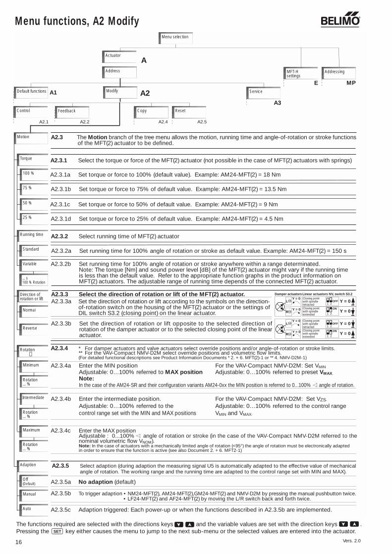
The functions required are selected with the directions keys and the variable values are set with the direction keys .Pressing the key either causes the menu to jump to the next sub-menu or the selected values are entered into the actuator.
A2.3.4c Enter the MAX positionAdjustable : 0...100% angle of rotation or stroke (in the case of the VAV-Compact NMV-D2M referred to thenominal volumetric flow VNOM).Note: In the case of actuators with a mechanically limited angle of rotation (<95°) the angle of rotation must be electronically adapted in order to ensure that the function is active (see also Document 2. + 6. MFT2-1)
A2.3.4a Enter the MIN position For the VAV-Compact NMV-D2M: Set VMIN
Adjustable: 0…100% referred to MAX position Adjustable: 0…100% referred to preset VMAX.
Note:In the case of the AM24-SR and their configuration variants AM24-0xx the MIN position is referred to 0...100% angle of rotation.
A2
A
ServiceDefault functions
Control
A2.3 The Motion branch of the tree menu allows the motion, running time and angle-of-rotation or stroke functions of the MFT(2) actuator to be defined.
Feedback Copy Reset
A1
A2.3.1 Select the torque or force of the MFT(2) actuator (not possible in the case of MFT(2) actuators with springs)Torque
A2.1 A2.2 A2.4 A2.5
A3
A2.3.2 Select running time of MFT(2) actuator
A2.3.2a Set running time for 100% angle of rotation or stroke as default value. Example: AM24-MFT(2) = 150 s
A2.3.2b Set running time for 100% angle of rotation or stroke anywhere within a range determinated.Note: The torque [Nm] and sound power level [dB] of the MFT(2) actuator might vary if the running timeis less than the default value. Refer to the appropriate function graphs in the product information onMFT(2) actuators. The adjustable range of running time depends of the connected MFT(2) actuator.
A2.3.3 Select the direction of rotation or lift of the MFT(2) actuator.
A2.3.4 * For damper actuators and valve actuators select override positions and/or angle-of-rotation or stroke limits.** For the VAV-Compact NMV-D2M select override positions and volumetric flow limits.(For detailed functional descriptions see Product Information Documents * 2. + 6. MFT(2)-1 or ** 4. NMV-D2M-1)
…s100 % Rotation
Running time
Standard
Variable
Direction ofrotation or lift
Normal
Reverse
Rotation
Minimum
Intermediate
Adaption
Off(Default)
Manual
Auto
Rotation…%
Rotation…%
Maximum
Rotation…%
➁
A2.3.1a Set torque or force to 100% (default value). Example: AM24-MFT(2) = 18 Nm100 %
75 % A2.3.1b Set torque or force to 75% of default value. Example: AM24-MFT(2) = 13.5 Nm
A2.3.1c Set torque or force to 50% of default value. Example: AM24-MFT(2) = 9 Nm50 %
25 % A2.3.1d Set torque or force to 25% of default value. Example: AM24-MFT(2) = 4.5 Nm
A2.3.4b Enter the intermediate position. For the VAV-Compact NMV-D2M: Set VZS.
Adjustable: 0…100% referred to the Adjustable: 0…100% referred to the control range control range set with the MIN and MAX positions VMIN and VMAX.
A2.3.5b To trigger adaption • NM24-MFT(2), AM24-MFT(2),GM24-MFT(2) and NMV-D2M by pressing the manual pushbutton twice. • LF24-MFT(2) and AF24-MFT(2) by moving the L/R switch back and forth twice.
A2.3.5a No adaption (default)
A2.3.5c Adaption triggered: Each power-up or when the functions described in A2.3.5b are implemented.
Y = 01 2
Y = 01
OFF2
Linear actuators NV, switch S3.2
Y = 0
L M
MR
Y = 0Damper actuators
ON
Y = 01 2
Y = 01
OFF2
Y = 0
L M
MR
Y = 0
ON
Closing pointwith spindleretractedClosing pointwith spindleextended
Closing pointwith spindleretractedClosing pointwith spindleextended
Addressing
Actuator
Menu selection
E MP
Address
Modify
Motion
MFT-Hsettings
Set the direction of rotation or lift according to the symbols on the direction-of-rotation switch on the housing of the MFT(2) actuator or the settings ofDIL switch S3.2 (closing point) on the linear actuator.
A2.3.3b Set the direction of rotation or lift opposite to the selected direction ofrotation of the damper actuator or to the selected closing point of the linearactuator.
A2.3.5 Select adaption (during adaption the measuring signal U5 is automatically adapted to the effective value of mechanicalangle of rotation. The working range and the running time are adapted to the control range set with MIN and MAX).
A2.3.3a

Menu functions, A2 Modify
17
A2ModifyDefault functions A1
Control Feedback Motion
Service
Reset
Reset
Last entry
All entries
A2.5 Reset any entry already verified with the SET key.
A2.5.1 Reset the last entry verified with the SET key.
A2.5.2 Reset all entries verified with the SET keysince the last power-up of the MFT-H device.
A2.1 A2.2 A2.3 A2.5
A3
ResetOriginal In the case of VAV-Compact (NMV-D2M) resets VMIN, VZS and VMAX to the settings that were stored
in the unit when it was delivered.
Menu selection
A MFT-Hsetting
Addressing
E MPAddress
Actuator
A2.4 Copy data record from one MFT(2) actuator to another.Typical applications: • Replacing a mechanically-defective MFT(2) actuator with a new unit • Assigning parameters to a small series of actuators
A2ModifyDefault functions A1
A2.4.1 Enter data from Actuator 1 into the MFT-H device
Control Feedback Motion
Copy Actuator-Actuator
Enter original
copy A2.4.2 Load data received from Actuator 1 into Actuator 2or other actuators.
Copying procedure:1. Connect the MFT-H device to the MFT(2) actuator from
which the data is to be taken.2. Use the ”Enter original” function on the MFT-H device
to transfer the data from the actuator to the device.3. Disconnect the MFT-H device from the first actuator
and connect it to the next actuator.4. Use the ”Copy” function on the MFT-H device to
enter the data into the next actuator.
Copy
Service
A2.1 A2.2 A2.3 A2.4
A3
Menu selection
A MFT-Hsetting
Addressing
E MPAddress
Actuator
ImportantThe duplicating function can only be used if the type and the actuatorconfiguration table are identical in both the original and the copy,otherwise a fault alarm will be given.
A2.4 Copy
A2.5 Reset
Vers. 2.0
SETThe functions required are selected with the directions keys . Pressing the key either causes the menu to jump to thenext sub-menu or the selected functions are initiated.
18
Menu functions, A3 Servie
Vers. 2.0
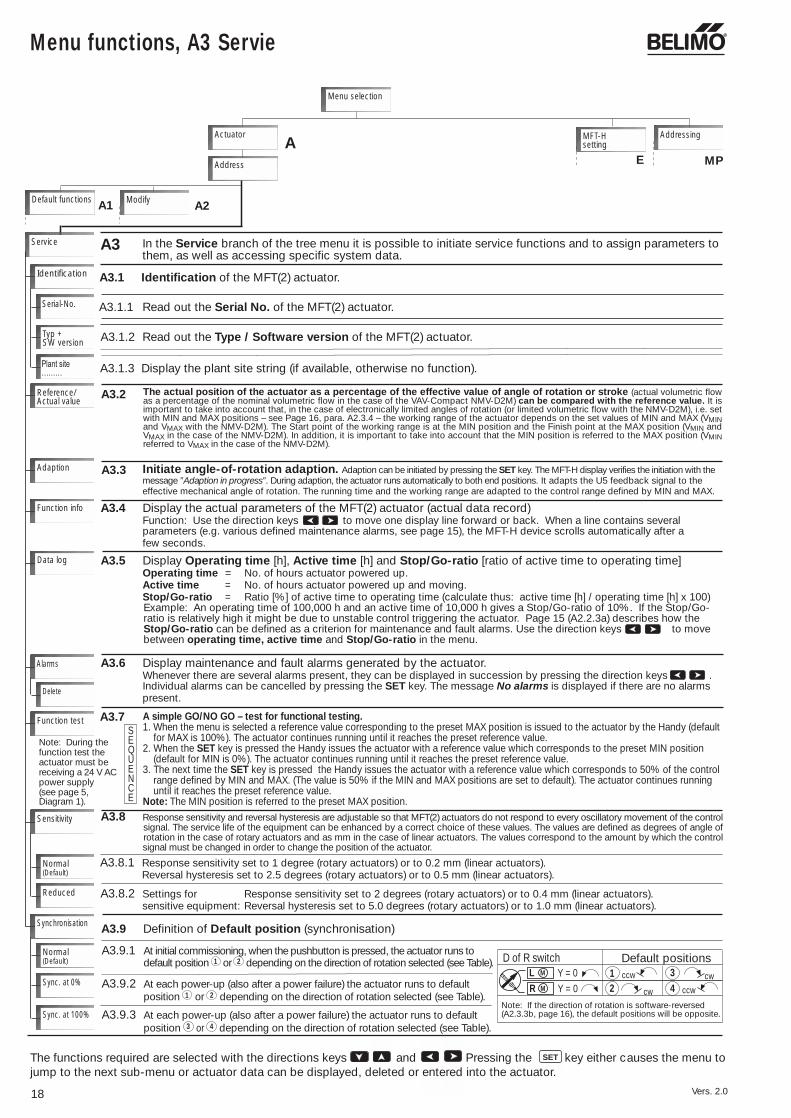
SETThe functions required are selected with the directions keys and Pressing the key either causes the menu tojump to the next sub-menu or actuator data can be displayed, deleted or entered into the actuator.
Initiate angle-of-rotation adaption. Adaption can be initiated by pressing the SET key. The MFT-H display verifies the initiation with themessage ”Adaption in progress”. During adaption, the actuator runs automatically to both end positions. It adapts the U5 feedback signal to theeffective mechanical angle of rotation. The running time and the working range are adapted to the control range defined by MIN and MAX.
A MFT-Hsetting
Addressing
Default functions
Menu selection
A1 A2Modify
A3 In the Service branch of the tree menu it is possible to initiate service functions and to assign parameters to them, as well as accessing specific system data.
A3.1.1 Read out the Serial No. of the MFT(2) actuator.
A3.1 Identification of the MFT(2) actuator.
Service
Identification
Serial-No.
Typ +SW version
Reference/Actual value
Adaption
Function info
Data log
A3.1.2 Read out the Type / Software version of the MFT(2) actuator.
A3.1.3 Display the plant site string (if available, otherwise no function).
A3.4 Display the actual parameters of the MFT(2) actuator (actual data record)Function: Use the direction keys to move one display line forward or back. When a line contains severalparameters (e.g. various defined maintenance alarms, see page 15), the MFT-H device scrolls automatically after afew seconds.
A3.5 Display Operating time [h], Active time [h] and Stop/Go-ratio [ratio of active time to operating time]Operating time = No. of hours actuator powered up.Active time = No. of hours actuator powered up and moving.Stop/Go-ratio = Ratio [%] of active time to operating time (calculate thus: active time [h] / operating time [h] x 100)Example: An operating time of 100,000 h and an active time of 10,000 h gives a Stop/Go-ratio of 10%. If the Stop/Go-ratio is relatively high it might be due to unstable control triggering the actuator. Page 15 (A2.2.3a) describes how theStop/Go-ratio can be defined as a criterion for maintenance and fault alarms. Use the direction keys to movebetween operating time, active time and Stop/Go-ratio in the menu.
Alarms
Delete
Function test
Sensitivity
Normal(Default)
Reduced
Synchronisation
Normal(Default)
Sync. at 0%
Sync. at 100%
A3.9 Definition of Default position (synchronisation)
A3.6 Display maintenance and fault alarms generated by the actuator.Whenever there are several alarms present, they can be displayed in succession by pressing the direction keys .Individual alarms can be cancelled by pressing the SET key. The message No alarms is displayed if there are no alarmspresent.
Default positionsD of R switch
cw
L M Y = 0R M Y = 0
Note: If the direction of rotation is software-reversed(A2.3.3b, page 16), the default positions will be opposite.
2ccw1
ccw
cw34
A3.7
A3.8.1 Response sensitivity set to 1 degree (rotary actuators) or to 0.2 mm (linear actuators).Reversal hysteresis set to 2.5 degrees (rotary actuators) or to 0.5 mm (linear actuators).
A3.8.2 Settings for Response sensitivity set to 2 degrees (rotary actuators) or to 0.4 mm (linear actuators).sensitive equipment: Reversal hysteresis set to 5.0 degrees (rotary actuators) or to 1.0 mm (linear actuators).
Plant site………
Note: During thefunction test theactuator must bereceiving a 24 V ACpower supply(see page 5,Diagram 1).
E MPAddress
Actuator
A3.2 The actual position of the actuator as a percentage of the effective value of angle of rotation or stroke (actual volumetric flowas a percentage of the nominal volumetric flow in the case of the VAV-Compact NMV-D2M) can be compared with the reference value. It isimportant to take into account that, in the case of electronically limited angles of rotation (or limited volumetric flow with the NMV-D2M), i.e. setwith MIN and MAX positions – see Page 16, para. A2.3.4 – the working range of the actuator depends on the set values of MIN and MAX (VMINand VMAX with the NMV-D2M). The Start point of the working range is at the MIN position and the Finish point at the MAX position (VMIN andVMAX in the case of the NMV-D2M). In addition, it is important to take into account that the MIN position is referred to the MAX position (VMINreferred to VMAX in the case of the NMV-D2M).
A3.3
A simple GO/NO GO – test for functional testing.1. When the menu is selected a reference value corresponding to the preset MAX position is issued to the actuator by the Handy (default for MAX is 100%). The actuator continues running until it reaches the preset reference value.2. When the SET key is pressed the Handy issues the actuator with a reference value which corresponds to the preset MIN position (default for MIN is 0%). The actuator continues running until it reaches the preset reference value.3. The next time the SET key is pressed the Handy issues the actuator with a reference value which corresponds to 50% of the control range defined by MIN and MAX. (The value is 50% if the MIN and MAX positions are set to default). The actuator continues running until it reaches the preset reference value.Note: The MIN position is referred to the preset MAX position.
A3.8 Response sensitivity and reversal hysteresis are adjustable so that MFT(2) actuators do not respond to every oscillatory movement of the control signal. The service life of the equipment can be enhanced by a correct choice of these values. The values are defined as degrees of angle of rotation in the case of rotary actuators and as mm in the case of linear actuators. The values correspond to the amount by which the control signal must be changed in order to change the position of the actuator.
SEQUENCE
A3.9.1 At initial commissioning, when the pushbutton is pressed, the actuator runs todefault position 1 or 2 depending on the direction of rotation selected (see Table).
A3.9.3 At each power-up (also after a power failure) the actuator runs to defaultposition 3 or 4 depending on the direction of rotation selected (see Table).
A3.9.2 At each power-up (also after a power failure) the actuator runs to defaultposition 1 or 2 depending on the direction of rotation selected (see Table).

SET
Menu functions, MFT-H settings E
19
MFT-Hsettings
Language
German
English
PP-interface
furtherlanguages
A2
AAddress
Menu selection
A3Default functions
Addressing MP
ModifyA1 Service
E Various modes of operation can be selected fromthe MFT-H settings branch of the tree menu.
E1 MFT-H language of communication
E1.1 Select German
E1.1 Select English
E1.3-E1.10 currently in preparation
E2 MFT-H device in PP-Interface modeWhen the MFT-H device is switched to this mode, the displayshows the message "PP-Interface ready....".The MFT-H can now be used as a level converter between anRS232 interface and a PP interface (ZIPfunction).
Software
SW-VersionSW version
MFT(2) actuator
~
T ~
1 2 3 5
U PP
- +
T
AC 24 VDC 24 V
!Connect throughsafetytransformer
SET
ONOFF ESC
MFT-H
PP-Interfaceready...
>Abort
RS232
D-S
ub
M
T
PP
RS 232 - cable(not included in
MFT-H)
D-SubPC
Wiring diagramif MFT-H is usedas ZIP
E3 Display of Software version loaded in MFT-H device
Actuator
MFT-H settings E
Vers. 2.0
The functions required are selected with the direction keys and the variable values set with the directions keys .Pressing the key either causes the menu to jump to the next sub-menu or the selected values are entered into the actuator.

20
MP-Addressing
MP The address of the actuator is entered in the Addressing branch of the menu.
MP1 Either PP or 1...8 (MP addresses) can be selected in the “Address” menu.• The PP address (PP = Point-to-Point) is selected if there is only one MFT(2) actuator connected to the
Handy (see Diagram 1 or Diagram 2 on Page 5). When an actuator is addressed with PP it is automaticallyparameterised for the classic mode of operation (no MP-Bus). In this case its control in the classic modecan be either modulating, 3-point, Open/Close or PWM. PP addressing is also used to reset an actuatorthat has previously been set for bus operation to the classic mode.
• MP addresses 1...8 (MP = Multi Point) is selected if there are several MFT(2) actuators connected to theHandy via the MP-Bus (see Diagram 3 on Page 5). This is because when there are several MFT(2) actuatorscommunicating over the MP-Bus each one must be clearly identifiable.When an MFT(2) actuator is addressed with an MP address 1...8 it is automatically parameterised for MP-Bus operation. In this case it is controlled digitally over the MP-Bus.
Addressing
Address
MFT-Hsettings
Menu selection
Actuator EA
Addressing
➄
Procedure for addressing an MFT(2) actuator:
1. Preselect the required address with the keys (Example: MP address 4)
SET
Addressing>Addressing: 4
ESC = Abort
2. Press the key and the following display will appear…
3. Perform the appropriate reset function on the MFT(2) actuator from the table below and according towhat the Handy demands.
Linear actuators NV24-MFT(2), NVF24-MFT(2), Press key S2 1xfor valves NVF24-MFT(2)-E (inside the housing cover)
Actuators without NM24-MFT(2), AM24-MFT(2), Press manual spring return GM24-MFT(2), NMV-D2M pushbutton 1x
Actuators with LF24-MFT(2), Move L/R switch back andspring return AF24-MFT(2) forth 1x (within 4 s)
Actuator family Actuator type Reset function
AddressingUnlatchactuatorESC = Abort
The required address will have beenassigned to the actuator when thisprocedure has been completed.
4. The following display appears briefly to show that the appropriate address has been assigned to theMFT(2) actuator:
Actuator programmed…
➄ Notes on parameterising AM24-SR’sThe AM24-SR and its configuration variants AM24-xx (e.g. AM24-001)do not have a bus capability and so cannot be addressed. In order toset their parameters these types can be accessed directly via theActuator/Address menu. In this case “PP” must be selected as theaddress.
Modifi-cation
Service
Actuator
Address
Menu selection
Select PP
MFT-Hsettings
Basicfunctions
R
L
Vers. 2.0

ESC
Examples of parameter assignment
21
Starting point for the examples of parameter assignment
1. Example: Parameterising an SRS function with a AM24-MFT(2) actuator
• When the MFT-H device is powered up, it always jumps directly to the menu step that was selectedwhen it was powered down. In the following Examples, parameter assignment always begins in the mainmenu. Press the key for at least 2 seconds in order to access the main menu.
• During parameter assignment, the MFT(2) actuator must be connected to the MFT-H device as shownin Diagrams 1 or 2 (see page 5).
Select menu>ActuatorData recordsMFT-H settings
Vers. 2.0
Press the key
Modifyoverwrite?SET=ExecuteESC=Abort
Display 2: Working rangeDC 3,5V-6.6 Vprogrammed.
SET
SET
ESC
a) Select menu
SET
1.1 Preparation
1.2 Parameter assignment
b) Ascertain default function nearest tothe final parameterising required.
To ascertain: The above data record is nearestto the default function SR (2...10 V DC). There-fore, the SR default function and the SR wiringdiagram shown on page 12, Section A1.1 canbe used as the basis.
Display
Display
b) Select Actuator menu
c) Select Default functionsmenu
Display
Default functions>SR (DC 2...10 V)PWM(0,59-2,93s)3-point
a) Definition of required parameters
ESC
e) Select Modify menu
Press the key
Press the key
SETPress the key
Press the key.
Display
Display
Display
Display
Display
Display
Display
SETPress the key
SETPress the key
Display
Display 1:during programming
Display 1:during programming
Display 1:during programming
Display 2:SR (DC 2...10V) programmed
SETPress the key
Actuator beingprogrammed...
Control signal DC V>DC 2-10 VDC 0-10 VDCV variable
Actuator beingprogrammed...
Press the for 2 seconds.
SET
f) Select Control menu
Display
Press the key
SET
g) Select Control signal DCV menu
Press the key
Press the key twice until thecursor is opposite DC variable.
Hold the key depressed untilStart shows 3.5 V.
Hold the key depressed untilFinish shows 6.6 V.
Press the key
d) Load default function SR (DC 2...10 V)into the MFT damper actuator.
Display
h) Selected DC variable menu
k) Labelling: Upon completion of pro-gramming, attach a label to the MFT(2)actuator showing the customised data(not identical to the AM24-SR basic type).A waterproof felt-tip penwill write on the specialstickers provided (use 2stickers if necessary).
i) Program SRS range
Actuator beingprogrammed...
DC (3,5 - 6,6V)Working range =
Data record parameterised
A 2-beep signal gives audible confirmation...
A 2-beep signal gives audible confirmation...
A 2-beep signal gives audible confirmation...
SETPress the key
Display 2:Control signal DCVhas been loaded....
Working range DC 3.5...6.6 VFunctionFeedback U5 DC 2...10 VTorque min. 18 NmAngle of rotation 95°Running time 150 sAngle-of-rotation adaption noneOverrides Min. (Min.Pos.) = 0%(referred to the full IP (Intermediate Pos.) = 50%angle of rotation of 95°) Max. (Max.Pos.) = 100%
Default functions>SR (DC 2...10 V)
PWM(0,59-2,93s)3-point
Actuator>Default functions
ModifyMFT-H settings
Select menu>Actuator
Data recordsMFT-H settings
Actuator>Default functions
ModifyService
Control signal DCV>DC 2-10 V
DC 0-10 V>DCV variable
DCV variable>Start Finish> 2.0V 10.0V
ESC = Abort
Actuator>Default functions
ModifyService
Modify>Control
FeedbackMotion
Control>Control signal DCV
Control signal PWM3-point
DCV variable>Start Finish> 3.5V 10.0VESC = Abort
DCV variable>Start Finish
3.5V >10.0VESC = Abort
DCV variable>Start Finish
3.5V >6.6VESC = Abort
DCV variable>Start Finish
3.5V >6.6VESC = Abort

22
Instructions for a Handy software upgrade
Before a software upgrade can be carried out a binary file containing the whole menu andthe languages (Version 2.0 has German and English only, other languages are in prepara-tion) must be loaded into the Handy. Use the “download20.exe” download program forthis purpose.The program can be started directly from the floppy disk (1.44 MB) or the hard disk.
System requirements and accessories needed:• PC with Windows 95/98/NT/2000 and at least 8 MB of RAM• Available serial interface COM1 or COM2• Mouse for operating the software• RS232 lead, for monitors, D-Sub 9-pin, male/female (no core crossing)
Procedure for upgrading MFT-H Handy’s:Remove the red cap from the interface connector on the Handy and use the 9-pinD-Sub lead to connect to one of the PC’s serial interfaces COM1 or COM2. Start the download program download20.exe from the hard disk or floppy andactivate the appropriate interface, e.g. COM2.
In the menu, click on [Download] [Load file]or � and ....
....open the binary file, e.g. <<mft-h-v20.bin>>
The file will have been loaded successfullyif the <<ready to program>> messageappears.
Vers. 2.0
Instructions for a Handy software upgrade
23
No actuatorSearchData records
>MFT-H settings
MFT-H settingsLanguagePP-Interface
>Software
SoftwareV1.0 26.03.98
>Cancel
SW-Upgrade>ExecuteCancel
SW-UpgradeReady...
<
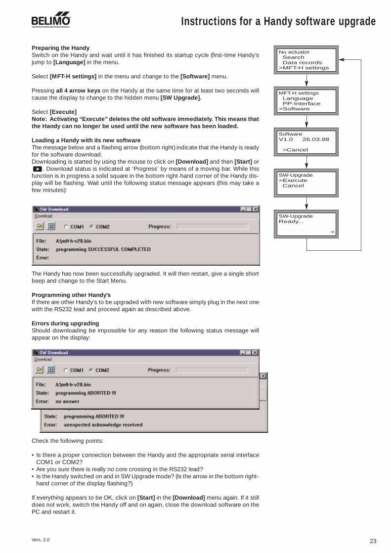
Preparing the HandySwitch on the Handy and wait until it has finished its startup cycle (first-time Handy’sjump to [Language] in the menu.
Select [MFT-H settings] in the menu and change to the [Software] menu.
Pressing all 4 arrow keys on the Handy at the same time for at least two seconds willcause the display to change to the hidden menu [SW Upgrade].
Select [Execute]Note: Activating “Execute” deletes the old software immediately. This means thatthe Handy can no longer be used until the new software has been loaded.
Loading a Handy with its new softwareThe message below and a flashing arrow (bottom right) indicate that the Handy is readyfor the software download.Downloading is started by using the mouse to click on [Download] and then [Start] or
. Download status is indicated at ‘Progress’ by means of a moving bar. While thisfunction is in progress a solid square in the bottom right-hand corner of the Handy dis-play will be flashing. Wait until the following status message appears (this may take afew minutes):
The Handy has now been successfully upgraded. It will then restart, give a single shortbeep and change to the Start Menu.
Programming other Handy’sIf there are other Handy’s to be upgraded with new software simply plug in the next onewith the RS232 lead and proceed again as described above.
Errors during upgradingShould downloading be impossible for any reason the following status message willappear on the display:
Check the following points:
• Is there a proper connection between the Handy and the appropriate serial interfaceCOM1 or COM2?
• Are you sure there is really no core crossing in the RS232 lead?• Is the Handy switched on and in SW Upgrade mode? (Is the arrow in the bottom right-
hand corner of the display flashing?)
If everything appears to be OK, click on [Start] in the [Download] menu again. If it stilldoes not work, switch the Handy off and on again, close the download software on thePC and restart it.
Vers. 2.0
EN
G-9
3001
-091
03-1
0.20
03-5
00 •
Prin
ted
in S
witz
erla
nd •
SIE
B •
Sub
ject
to
tech
nica
l cha
nges
Air applications Water applications
Standard actuators andspring-return actuators forair control dampers inHVAC systems
Innovation, Quality and Consultancy:A partnership for motorizing HVAC actuators
Safety actuators formotorizing fire and smokeextraction dampers
VAV systems for individualroom air control
Mixing actuators andmotorized ball valves forHVAC water circuits
Globe valves and intelligentlinear actuators – also forleading makes of valve
Belimo Headquarters
CH BELIMO Holding AGBrunnenbachstrasse 18340 Hinwil, SwitzerlandTel. +41 (0)43 843 61 11Fax +41 (0)43 843 62 [email protected]
Belimo Subsidiaries
AT/ BELIMO AutomationHR/ Handelsgesellschaft m.b.H.HU/ Geiselbergstrasse 26–32SI/ 1110 Wien, AustriaSK Tel. +43 (0)1 749 03 61-0
Fax +43 (0)1 749 03 [email protected]
AU BELIMO Actuators Pty. Ltd.Unit 10, 266 Osborne AvenueClayton South, VIC 3169AustraliaTel. +61 (0)3 9551 0201Fax +61 (0)3 9551 [email protected]
CA BELIMO Aircontrols (CAN), Inc.5716 Coopers Ave., Units 14&15Mississauga, Ontario L4Z 2E8CanadaTel. +1 (1)905 712 31 18Fax +1 (1)905 712 31 [email protected]
CH BELIMO Automation AGSales SwitzerlandBrunnenbachstrasse 18340 Hinwil, SwitzerlandTel. +41 (0)43 843 62 12Fax +41 (0)43 843 62 [email protected]
DE BELIMO Stellantriebe Vertriebs GmbH Welfenstr. 27, Postfach 72 02 3070599 Stuttgart, GermanyTel. +49 (0)711 1 67 83-0Fax +49 (0)711 1 67 [email protected]
ES BELIMO Ibérica de Servomotores, S.A.C/San Romualdo, 12–1428037 Madrid, Spain Tel. +34 91 304 11 11Fax +34 91 327 25 [email protected]
FR BELIMO ServomoteursZ.A. de Courtry33, Rue de la Régale77181 Courtry, FranceTél. +33 (0)1 64 72 83 70Fax +33 (0)1 64 72 94 [email protected]
GB BELIMO Automation UK LimitedThe Lion CentreHampton Road West Feltham, Middlesex, Great Britain TW 13 6DSTel. +44 (0)20 8755 4411Fax +44 (0)20 8755 [email protected]
HK BELIMO Actuators Ltd.Room 208, 2/FNew Commerce Centre
19 On Sum Street, Shatin, N.T.Hong KongTel. +852 26 87 17 16Fax +852 26 87 17 [email protected]
PL BELIMO Silowniki S.A.ul. Zagadkl 2102-227 Warszawa, PolandTel. +48 (0)22 886 53 05Fax +48 (0)22 886 53 [email protected]
SG BELIMO Actuators Pte Ltd2, Jurong East Street 21#04-31F IMM BuildingSingapore 609601Tel. +65 6564 9828Fax +65 6564 [email protected]
US BELIMO Aircontrols (USA), Inc.43 Old Ridgebury RoadP.O. Box 2928Danbury, CT 06810 USATel. +1 (1)203 791 99 15Fax +1 (1)203 792 29 [email protected] www.belimo.com
Belimo Representatives andAgencies
AE BELIMO TradingMiddle East OfficeP.O. Box 73885 Dubai, U.A.E.Tel. +971 (0)4 295 9670Fax +971 (0)4 295 [email protected]
IE Safegard Systems Ltd.Systems House, Unit 34Southern Cross Business ParkBray, Co Wicklow, IrelandTel. +353 (0)1 2761600Fax +353 (0)1 [email protected]
IL Shemer RepresentationsP.O. Box 29656101 Yehud, IsraelTel. +972 3 536 51 67Fax +972 3 536 05 [email protected]
IN BELIMO Vitek Air ControlsC-114 Lancelot, First Floor S.V. Road, Borivali (West)Mumbai 400 092, IndiaTel. +91 22 5695 9439Fax +91 22 2806 [email protected]
IS Hitatækni ehf.Langholtsvegi 109104 Reykjavik, IcelandTel. +354 5 88 60 70Fax +354 5 88 60 [email protected]
IT BELIMO Servomotori S.r.l.Via Stezzano, 524050 Zanica BG, ItalyTel. +39 035 67 26 82Fax +39 035 67 02 [email protected]
KR HANMO Corporation3rd Floor, Yeosam Bldg. 648-23Gangnam-Ku, Seoul, KoreaTel. +822 3453 8225Fax +822 3453 8228
LB Energy Center (EC)Hamra, Leon Street, Shatilla, Bldg. 4th Floor, P.O. Box 113-6955Beirut, LebanonTel. +961 (0)1 35 38 23Fax +961 (0)1 35 38 [email protected]
NL/ BELIMO Servomotoren BV BE/ BENELUXLU Postbus 300, 8160 AH Epe
Radeweg 25, 8171 MD VaassenNetherlandsTel. +31 5 78 57 68 36Fax +31 5 78 57 69 [email protected]
NO BELIMO Spjeldmotorer A/SKonowsgate 5 0192 Oslo 1, NorwayTel. +47 22 70 71 71Fax +47 22 70 71 [email protected]
PH BELIMO Actuators PhilippinesRm.# 507 Anita Build., 5th Floor1300 Quezon Ave.,Cor.South Ave.1103 Quezon City, PhilippinesTel. +63 (2)373 5440Fax +63 (2)373 [email protected]
RO SC Mano Construct srlStr. Cameliei nr 5, sector 1Bucuresti, RomaniaTel. +40 212 126 993Fax +40 212 126 [email protected]
RU BELIMO Servomotors Russia Ltd.Nizhnyaya Pervomaiskaya, 46 Bld.1, Office 303105203 Moscow, Russia Tel. +7 095 965 74 64Fax +7 095 965 74 [email protected]
SE BELIMO ABHägerstens Allé 88129 37 Hägersten, SwedenTel. +46 (0)8 464 07 00Fax +46 (0)8 97 85 75 [email protected]
SY Philippe A. JebranP.O. Box 7791Damascus, SyriaTel. +963 11 231 6586Fax +963 11 231 [email protected]
TR BELIMO Otomasyon A.S.Keyap Sitesi No. 20TR-34775 Y. DudulluIstanbul, TurkeyTel. +90 (0)216 527 98 70Fax +90 (0)216 527 98 [email protected]
TW Chianseng Enterprise Co. Ltd.2F, No. 21, Tong Fong StreetTaipei, TaiwanTel. +886 2 27 08 77 80Fax +886 2 27 02 90 [email protected]
UA BELIMO Ukraine S.A.R.34-A, Ul. Yurkovskaya, Appt.No 2254080 Kiev, UkraineTel. /Fax +380 44 463 [email protected]
ZA BELIMO Actuators Southern Africa ccP. O. Box 2483Alberton 1450, South AfricaTel. +27 (0)11 868 5681Fax +27 (0)11 900 [email protected]
BG BELIMO Bulgaria Ltd.j.k. Lagera, 3 Smolyanska Str.bl. 56, entr. B, ap. 501612 Sofia, BulgariaTel. +3592 952 3470/1Fax +3592 545 [email protected]
CN BELIMO Actuators Ltd.Room 1305, Financial SquareNo. 333 Jiujiang Road200001 Shanghai, ChinaTel. +86 21 6360 8980Fax +86 21 6360 [email protected]
CN BELIMO BeijingRm 605, Beijing Hai Chang Edifice, 44, Liang Ma Qiao Road Chao Yang District100016 Beijing, ChinaTel. +86 10 6462 1382Fax +86 10 6462 [email protected]
CY R.E.S. Ltd.P.O. Box 8297Nicosia, CyprusTel. +357 (0)2 51 10 07Fax +357 (0)2 49 65 [email protected]
CZ BELIMO CZ (Ing. Ivar Mentzl)Charkovská 1610100 Praha 10, Czech RepublicTel. +420 (0)2 717 4 0 311Fax +420 (0)2 717 43 057 [email protected]
DK BELIMO A/SThomas Helstedsvej 7A8660 Skanderborg, DenmarkTel. +45 86 52 44 00Fax +45 86 52 44 [email protected]
EE BELIMO Balticum ASTüri 10 d11313 Tallinn, EstoniaTel. +372 6 140 811Fax +372 6 140 [email protected]
FI Oy Suomen BELIMO AbInsinöörinkatu 200810 Helsinki, FinlandTel. +358 (0)424 651 1Fax +358 (0)424 651 [email protected]
GR BELIMO Air Controls29, Tagm. Plessa, KallitheaGR 17674 Athens, GreeceTel. +30 2 10 94 00 766Fax +30 2 10 94 00 [email protected]
Contact the following for further information: