24590-bof-nt d-dep-00004 issued by rpp-wtppdc · rpp-wtppdc appurtenances dep-vsl-00004a...
TRANSCRIPT
24590-BOF-Nt D-DEP-00004 ISSUED BY Rev. 1
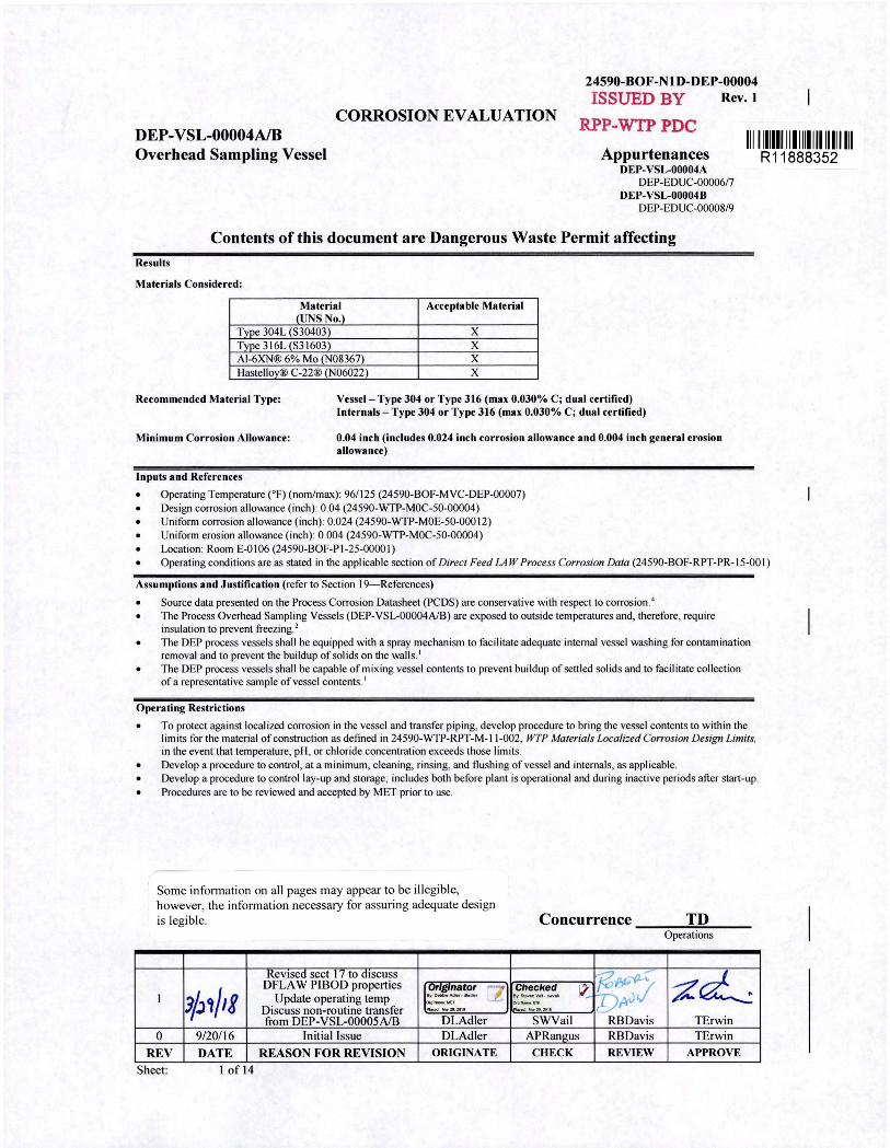
CORROSION EVALUATION DEP-VSL-00004A/B Overhead Sampling Vessel
RPP-WTPPDC
Appurtenances DEP-VSL-00004A
DEP-EDUC-00006/7 DEP-VSL-00004B
DEP-EDUC-00008/9
II I I IIIIII II I 111111111111111
Contents of this document are Dangerous Waste Permit affecting Results
Materials Considered:
Material Acceptable Material <UNS No.)
Type 304L (S30403) X Type 3 I 6L (S31603) X Al-6XN® 6% Mo (N08367) X Hastellov® C-22® (N06022) X
Recommended Material Type: Vessel - Type 304 or Type 316 (max 0.030% C; dual certified) Internals - Type 304 or Type 316 (max 0.030% C; dual certified)
Minimum Corrosion Allowance:
Inputs and References
0.04 inch (includes 0.024 inch corrosion allowance and 0.004 inch general erosion allowance)
• Operating Temperature (°F) (nom/max): 96/125 (24590-BOF-MVC-DEP-00007) • Design corrosion allowance (inch): 0.04 (24590-WTP-M0C-50-00004) • Uni form corrosion allowance (inch): 0.024 (24590-WTP-M0E-50-000 12) • Uni form erosion allowance (inch): 0.004 (24590-WTP-M0C-50-00004) • Location: Room E-0106 (24590-BOF-Pl-25-0000 1)
R11888352
• Operating conditions are as stated in the applicable section of Direct Feed LAW Process Corrosion Data (24590-BOF-RPT-PR- I 5-00 I )
Assumptions and Justification (refer to Section 19- References)
• Source data presented on the Process Corrosion Datasheet (PCDS) are conservative with respect to corros ion. 4
• The Process Overhead Sampling Vessels (DEP-VSL-00004A/B) are exposed to outside temperatures and, therefore, requi re insulation to prevent freezing. 2
• The DEP process vessels shall be equipped with a spray mechanism to fac ilitate adequate internal vessel washing for contaminati on removal and to prevent the bui ldup of solids on the wall s.'
• The DEP process vessels shall be capable of mixing vessel contents to prevent buildup of settled solids and to faci litate coll ection of a representative sample of vesse l contents. 1
Operating Restrictions
• To protect against localized corrosion in the vessel and transfer piping, develop procedure to bring the vessel contents to within the limits for the material of construction as defined in 24590-WTP-RPT-M-11-002, WTP Materials locali=ed Corrosion Design limits, in the event that temperature, pH, or chloride concentration exceeds those limits.
• Develop a procedure to control, at a minimum, cleaning, rinsing, and flushing of vessel and internals, as applicable. • Develop a procedure to control lay-up and storage; includes both before plant is operational and during inactive periods after start-up. • Procedures are to be reviewed and accepted by MET prior to use.
Some infonnation on all pages may appear to be illegible, however, the information necessary fo r assuring adequate design is legibl e.
Revised sect 17 to discuss
'JjJ,J,g DFLA W PIBOD properties [-?~~~! ~z
I Update operating temp 0.11-,-it:f
Discuss non-routine transfer _ , ...,21, 201,
from DEP-VSL-00005 AfB DLAdler 0 9/20/16 Initial Issue DLAdler
REV DATE REASON FOR REVISION ORIGINATE
Sheet: I of 14
Concurrence TD -------------0 p era ti on s
%~--(}.,• ;Z~ Checked v_ D~,/ er:s.....,v ... ,_ .. Or11-IINI
lu, ?f, 2011
SWVail RBDavis TErwin APRangus RBDavis TErwin
CHECK REVIEW APPROVE
24590-BOF-NlD-DEP-00004 Rev.1
CORROSION EVALUATION
Please note that source, special nuclear and byproduct materials, as defined in the Atomic Energy Act of 1954 (AEA), are regulated at the U.S. Department of Energy (DOE) facilities exclusively by DOE acting pursuant to its AEA authority. DOE asserts, that pursuant to the AEA, it has sole and exclusive responsibility and authority to regulate source, special nuclear, and byproduct materials at DOEowned nuclear facilities. Information contained herein on radionuclides is provided for process description purposes only.
DEP-VSL-00004A/B: Sheet: 2 of 14
This bound document contains a total of 14 sheets.
CORROSION EVALUATION
Corrosion/Erosion Detailed Discussion
24590-BOF-NlD-DEP-00004 Rev. I
DEP-VSL-00004A/B receive evaporator condensate from DEP-COND-0000 I, caustic scrubber fluids from the LAW LVP system, and sump pump discharge from DEP-SUMP-00002A/B, DEP-SUMP-00004A/B, NLD-SUMP-00031, and NLD-SUMP-00032.
Overhead sampling vessel transfer pumps (DEP-PMP-00004A/B/C) are used to recirculate DEP-VSL-00004A/B contents to a sample connection where samples are collected and fluid is returned to the tank through the eductors. Each batch is sampled and characterized before sending to the process condensate lag storage vessels (DEP-VSL-00005A/B). Off-spec condensate in DEP-VSL-00004A/B can be recycled to DEP-VSL-00002. In the event of an overflow, the liquid will flow by gravity into DEP-VSL-00001.
The vessel contents can be sampled and the vessel are monitored for level, pressure, and temperature.
The overhead sampling vessels are equipped with vessel mixing eductors to homogenize the contents and allow a representative sample to be taken. DEP-VSL-00004A/B are passively purged with air drawn through the vessel head space and are vented to the Vessel Vent Header. This vessel will have capability to add process service water (PSW) for washing.
If the contents of the process condensate lag storage vessels (DEP-VSL-00005A/B) do not meet the requirements for transfer to LERf/ETf, the contents can be transferred to DEP-VSL-00004A/B. Once transferred to DEP-VSL-00004A/B, off-spec effluent can be returned to the evaporator process or be returned to the tank farms.
1 General/Uniform Corrosion Analysis
a Background General or uniform corrosion is corrosion that is distributed uniformly over the surface of a material without appreciable localization. This leads to relatively uniform thinning on sheet and plate materials and general thinning on one side or the other ( or both) for pipe and tubing. It is recognized by a roughening of the surface and by the presence of corrosion products. The mechanism of the attack is an electrochemical process that takes place at the surface of the material. Differences in composition or orientation between small areas on the metal surface create anodes and cathodes that facilitate the corrosion process.
b Component-Specific Discussion This vessel primarily contains transfers from the LVP-TK-0000 I and process condensate from DEP-EV AP-0000 I. The vessel contents are at 122 °f and pH 9 .5. The normal pH, chloride concentration, and temperatures are such that either Type 304L or 3 l 6L would be acceptable. The solution is mixed and sampling is performed. The uniform corrosion rate is low under these conditions; a minimum 0.04 inch corrosion allowance is recommended.
2 Pitting Corrosion Analysis
Pitting is localized corrosion of a metal surface that is confined to a point or small area and takes the form of cavities. Chloride is known to cause pitting in acid and neutral solutions. In this vessel, the normal chemistry, pH and temperatures are such that either Type 304L or 316L stainless steel would be acceptable. The vessel is operated such that conditions do not promote localized corrosion. The solution in the vessel is not left stagnant; tank mixing eductors are used to entrain solids and mix the vessel contents.
The chemistry and operating conditions in this vessel fall within the limits established for 300 series stainless steel in Table 1-2 of WTP Materials Localized Corrosion Design limits report, 24590-WTP-RPT-M-11-002. For convenience, this comparison is documented on page 6 of this corrosion evaluation.
3 Crevice Corrosion Analysis
Crevice corrosion is a form oflocalized corrosion of a metal or alloy surface at, or immediately adjacent to, an area that is shielded from full exposure to the environment because of close proximity of the metal or alloy to the surface of another material or an adjacent surface of the same metal or alloy. Crevice corrosion is similar to pitting in mechanism.
Crevices in this vessel are limited by the design and fabrication practice. All welding uses butt welds, and crevices are limited to wash ring hangers and other internals associated with the mixing eductors. With the stated operating conditions, the 300 series stainless steels will be acceptable.
The chemistry and operating conditions in this vessel fall within the limits established for 300 series stainless steel in Table 1-2 of 24590-WTP-RPT-M-11-002.
4 Stress Corrosion Cracking Analysis
Stress corrosion cracking (SCC) is the cracking of a material produced by the combined action of corrosion and sustained tensile stress (residual or applied). The exact amount of chloride required to cause stress corrosion cracking is unknown. In part this is because the amount varies with temperature, metal sensitization, the environment, and also because chloride tends to concentrate under heat transfer conditions, by evaporation, and electrochemically during a corrosion process. Hence, even concentrations as low as IO ppm can lead to cracking under some conditions. Generally, as seen in Sedriks (1996) and Davis (1987), stress corrosion cracking does not usually occur below about 140 °f for sensitized alloys. With the proposed normal conditions, a 300 series stainless steel is expected to be acceptable.
The chemistry and operating conditions in this vessel fall within the limits established for 300 series stainless steel in Table 1-2 of 24590-WTP-RPT-M-11-002.
DEP-VSL-00004A/B: Sheet: 3 of 14
CORROSION EVALUATION
5 End Grain Corrosion Analysis
24590-BOF-NlD-DEP-00004 Rev. I
End grain corrosion is preferential corrosion which occurs along the cold working direction of wrought stainless steels when exposed to highly oxidizing acidic conditions. End grain corrosion is exclusive to metallic product forms with exposed end grains from shearing or mechanical cutting. Such conditions are not present in the pressure boundary design and nozzles; vessels are all butt-weld joints. End grain corrosion is not a concern for the vessel pressure boundary materials.
6 Weld Corrosion Analysis
Corrosion at the welds includes both the weld heat affected zone (HAZ) and filler metal. Corrosion depends on the base metal chemistry, welding parameters and filler metal chemistry. The normal uniform corrosion is influenced by the microstructural changes to the alloy. The microstructural changes that contribute to corrosion are solidification micro-segregation that transforms to precipitates, grain boundary coarsening, and carbide precipitation at the grain boundaries. These metallurgical conditions are mitigated by project controls placed on welding parameters and filler metal chemistry. The low carbon content in austenitic stainless steels and nickel alloys prevent base metal sensitization during welding. Controls on the cover gas, heat input, and interpass temperature limit the heat tint. Matching filler metal should be selected. Corrosion at welds is not considered a problem in the proposed environment. Providing correct weld procedures are followed, no preferential corrosion of weld beads or heat-affected wnes occurs in nitric acid or alkaline based stream. No additional allowance is made for weld bead corrosion.
7 Microbiologically Influenced Corrosion Analysis
Microbiologically influenced corrosion (MIC) refers to corrosion affected by the presence or activity, or both, of microorganisms. Typically, with the exception of cooling water systems, MIC is not observed in operating systems. The proposed operating conditions are not ideal for microbial growth; therefore, the potential for MIC in the vessels is small.
8 Fatigue/Corrosion Fatigue Analysis
Fatigue is the process of progressive localized permanent structural change occurring in a material subjected to fluctuating stresses at less than the ultimate tensile strength of the material. Corrosion fatigue is the process wherein a metal fractures prematurely under conditions of simultaneous corrosion and repeated cyclic loading at lower stress levels or fewer cycles than would be required to cause fatigue of that metal in the absence of the corrosive environment. Corrosion fatigue is not an issue because the number of loading cycles for the operation window is limited and low. The number of thermal cycles (room temperature to 126 °F max) is also low.
9 Vapor Phase Corrosion Analysis
Conditions in the vapor phase and at the vapor/liquid interface can be different than those present in the liquid. The vapor space corrosion is self-limiting due to the passive film. Also, the layers of deposited corrosion product on top of the passive film act as barriers that reduce mass transport necessary for corrosion. Corrosion rates of materials exposed to vapors in the headspace are never greater than the corrosion during immersion service. The corrosion at the liquid air interface (LAI) is an oxygen-concentration cell resulting from the alternate wetting and drying occurring at the interface. Vessels that operate at the same liquid level and form a surface crust are more susceptible to LAI corrosion. Corrosion at the LAI could be similar to immersion service and not greater. WTP vessels also have the protective passive film at the LAI which reduces corrosion. Further, the liquid level fluctuates between the minimum and maximum level, rather than maintaining a constant level. As compared to the corrosion in the immersion section, the corrosion rates in the vapor space are lower. Vapor phase corrosion is not a concern.
10 Erosion Analysis
Erosion is the progressive loss of material from a solid surface resulting from mechanical interaction between that surface and a fluid, a multi-component fluid, or solid particles carried with the fluid. Velocities within the vessel are expected to be below 12 ft/s. Erosion allowance of0.004 inch for Type 304L and 316L stainless steel components with solids content less than 2 wt% at velocities below 12 ft/s is based on 24590-WTP-M0C-50-00004, Wear Allowance for WTP Waste Slurry Systems.
The recommended general erosion wear allowance provides sufficient protection for erosion of the vessel walls. Conditions do not suggest that localized erosion will occur; therefore, no localized erosion allowance is necessary for the vessel.
11 Galling of Moving Surfaces Analysis
Where two metals are moving in contact with each other without lubrication, there is a risk of damage to their surfaces. No moving unlubricated surfaces are present within the vessel; therefore, galling is not a concern.
12 Fretting/Wear Analysis
Fretting corrosion refers to corrosion damage caused by a slight oscillatory slip between two surfaces. Similar to galling but at a much smaller movement, the corrosion products and metal debris break off and act as an abrasive between the surfaces, producing a classic three body wear problem. This damage is induced under load and repeated relative surface motion. Conditions which lead to fretting are not present in this vessel; therefore, fretting is not a concern.
DEP-VSL-00004A/B: Sheet: 4 of 14
CORROSION EVALUATION
13 Galvanic Corrosion Analysis
24590-BOF-NlD-DEP-00004 Rev. I
Galvanic corrosion is accelerated corrosion caused by the potential difference between the two dissimilar metals in an electrolyte. A potential difference of greater than 200 m V is necessary to drive corrosion. One material becomes the anode and the other the cathode. Corrosion occurs on the anode material at the interface where the potential gradient is the greatest. The potential difference for any combination of alloys used in these vessels is not sufficient for galvanic currents to overcome the passive protective film. Therefore, it can be stated that conditions which lead to galvanic corrosion are not present in this vessel.
14 Cavitation Analysis
Cavitation is the formation and rapid collapse of cavities or bubbles of vapor or gas within a liquid resulting from mechanical or hydrodynamic forces. Cavitation is typically associated with pumps and orifice plates; this vessel has neither. The alloys selected display a superior resistance to cavitation, and WTP vessel design limits conditions which lead to cavitation; therefore, cavitation is not a concern.
15 Creep Analysis
Creep is time-dependent strain occurring under stress and is described as plastic flow, yielding at stresses less than the yield strength. Creep is only experienced in plants operating at high temperatures. Temperatures much greater than one half the absolute melting temperature of the alloy are necessary for thermally activated creep to become a concern. The vessel operating and design temperatures are too low to lead to creep; therefore, creep is not a concern.
16 Inadvertent Nitric Acid Addition
At this time, the design does not provide for the regular use of nitric acid reagent in this system. Addition of nitric acid into the system would require operator intervention to complete the routing. Nitric acid is a known inhibitor solution for austenitic stainless steels and nickel-based alloys. The presence of nitric acid is not a concern for the stainless steel; especially at the operating temperatures listed.
17 Conclusion and Justification
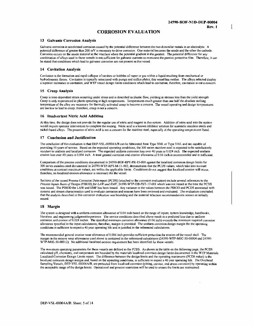
The conclusion of this evaluation is that DEP-VSL-00004A/B can be fabricated from Type 304L or Type 316L and are capable of providing 40 years of service. Based on the expected operating conditions, the 300 series stainless steel is expected to be satisfactorily resistant to uniform and localized corrosion. The expected uniform corrosion loss over 40 years is 0.024 inch. The expected uniform erosion loss over 40 years is 0.004 inch. A total general corrosion and erosion allowance of0.04 inch is recommended and is sufficient.
Comparison of the process conditions documented in 24590-BOF-RPT-PR-15-001 against the localized corrosion design limits for 300 series stainless steel documented in 24590-WTP-RPT-M-11-002, demonstrates that the PCDS values, which take into account conditions at contract maximum values, are within the applicable limits. Conditions do not suggest that localized erosion will occur; therefore, no localized erosion allowance is necessary for the vessel.
Sections of the issued Process Corrosion Data report (PCDS) (attached to the corrosion evaluation) include several references to the Process Inputs Basis of Design (PIBOD)for LAW and EMF, 24590-WTP-DB-PET-17-001 which was not issued at the time the PCDS was issued. The PIBOD for LAW and EMF has been issued. Any variance in the values between the PIBOD and PCDS associated with streams and stream characteristics used to evaluate corrosion and erosion have been reviewed and evaluated. The evaluation concluded that the analysis described in this corrosion evaluation was bounding and the material selection recommendations remain as initially issued.
18 Margin
The system is designed with a uniform corrosion allowance of 0.04 inch based on the range of inputs, system knowledge, handbooks, literature, and engineering judgment/experience. The service conditions described above result in a predicted loss due to uniform corrosion and erosion of0.028 inches. The specified minimum corrosion allowance (0.04 inch) exceeds the minimum required corrosion allowance specified in the input calculations; therefore, margin is provided. The uniform corrosion design margin for the operating conditions is sufficient to expect a 40 year operating life and is justified in the referenced calculations.
The recommended general erosion wear allowance of0.004 inch provides sufficient protection for erosion of the vessel shell. The margin in the erosive wear allowances used above is contained in the referenced calculations (24590-WTP-M0C-50-00004 and 24590-WTP-M0E-50-00012). No additional localized erosion requirement has been identified for these vessels.
The maximum operating parameters for these vessels are defined in the PCDS. As shown in the table on the following page, the PCDS calculated pH, chemistry, and temperature are bounded by the materials localized corrosion design limits documented in the WTP Materials Localized Corrosion Design Limits report. The difference between the design limits and the operating maximums (PCDS value) is the localized corrosion design margin and, based on the operating conditions, is sufficient to expect a 40 year operating life. The Overhead Sampling Vessels, DEP-VSL-00004A/B, are protected from localized corrosion (pitting, crevice, and stress corrosion) by operating within the acceptable range of the design limits. Operational and process restriction will be used to ensure the limits are maintained.
DEP-VSL-00004A/B: Sheet: 5 of 14
CORROSION EVALUATION
24590-BOF-NlD-DEP-00004 Rev. I
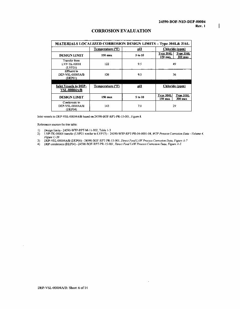
MATERIALS LOCALIZED CORROSION DESIGN LIMITS -Type 304L& 316L
Temuerature {°F} Jill Chloride (1mm}
DESIGN LIMIT 150 max 5 to 10 Type 304L I Type 316L 150 max 300 max
Transfer from LVP-TK-00001 122 9.5 49
(LVP21) Effluent to
DEP-VSL-00005A/B 126 9.5 36 (DEPOI)
Inlet Vessels to DEP- Temuerature (°F} Jill Chloride (uuml VSL-00004A/B
DESIGN LIMIT 150 max 5 to 10 Type304LI Type316L 150 max I 300 max
Condensate to DEP-VSL-00004A/B 143 7.0 29
(DEP04)
Inlet vessels to DEP-VSL-00004A/B based on 24590-BOF-RPT-PR-15-001, Figure 8.
References sources for this table:
I) Design limits-24590-WTP-RPT-M-l l-002, Table 1-3 2) LVP-TK-0000 I transfer (LVP2 I similar to LVPI 7) - 24590-WTP-RPT-PR-04-0001-04, WTP Process Corrosion Data - Volume 4,
Figure C-39 3) DEP-VSL-00004A/B (DEPOI)- 24590-BOF-RPT-PR-15-001, Direct Feed LAW Process Corrosion Data, Figure A-7 4) DEP condensers (DEP04) - 24590-BOF-RPT-PR-l 5-00 I, Direct Feed LAW Process Corrosion Data, Figure A-5
DEP-VSL-00004A/B: Sheet: 6 of 14

CORROSION EVALUATION 19 References:
24590-BOF-NlD-DEP-00004 Rev. I
1. 24590-BOF-3ZD-25-00001, WTP Direct Feed Low Activity Waste (DFLAW) Facility and System Design Descriptions. 2. 24590-BOF-MVC-DEP-00007, Process Data/or the Overhead Sampling Vessels (DEP-VSL-00004AIB) and Pumps DEP-PMP-
00004AIB). 3. 24590-BOF-Pl-25-00001, Balance of Facilities LAW EjJ/uent Process Bldg & LAW EfJ/uent Drain Tank Bldg General A"angement
Plan at Elev 0 Ft - 0 In. 4. 24590-BOF-RPT-PR-15-001, Direct Feed LAW Process Corrosion Data. 5. 24590-WTP-DB-PET-17-001, Process Inputs Basis of Design (PIBOD) for LAW and EMF. 6. 24590-WTP-M0C-50-00004, Wear Allowance/or WTP Waste Slurry Systems with ECCN 24590-WTP M0E-50-000I2. 7. 24590-WTP-RPT-M-11-002, WTP Vessel Locali=ed Co"osion Limit Analysis Report. 8. Davis, JR (Ed), 1987, Corrosion, Vol 13, In "Metals Handbook", ASM International, Metals Park, OH 44073 9. Sedriks, AJ, 1996, Corrosion a/Stainless Steels, John Wiley & Sons, Inc., New York, NY 10158
Additional Reading • 24590-BOF-M6-DEP-00004001, P&ID- BOFIEMF Direct Feed LAW EMF Process System Overhead Sampling Vessel - DEP-VSL-
00004A. • 24590-BOF-M6-DEP-00004002, P&ID- BOFIEMF Direct Feed LAW EMF Process System Overhead Sampling Vessel -DEP-VSL-
00004B. • 24590-BOF-MVD-DEP-00005, Mechanical Data Sheet - 24590-BOF-MV-DEP-VSL-00004A/00004B - Overhead Sampling Vessel. • 24590-WTP-RPT-M-04-0008, Evaluation a/Stainless Steel and Nickel Alloy Wear Rates in WTP Waste Streams at Low Velocities. • CCN 130170, Blackburn, LD to PG Johnson, Internal Memo, Westinghouse Hanford Co, Evaluation of 240-AR Chloride Limit,
August 15, 1991. • CCN 130171, Ohl, PC to PG Johnson, Internal Memo, Westinghouse Hanford Co, Technical Bases/or Cl- and pH Limits/or Liquid
Waste Tank Cars, MA: PCO:90/01, January 16, 1990. • CCN 130172, Divine, JR, 1986, Letter to A.J. Diliberto, Reports of Experimentation, Battelle, Pacific Northwest Laboratories,
Richland, WA 99352. • CCN 130173, Dillon, CP (Nickel Development Institute), Personal Communication to J R Divine (ChemMet, Ltd., PC), 3 Feb 2000. • Agarwal, DC, Nickel and Nickel Alloys, In: Revie, WW, 2000. Uhlig's Corrosion Handbook, 2nd Edition, Wiley-Interscience, New
York, NY 10158. • Danielson, MJ & SG Pitman, 2000, Corrosion Tests of 316L and Haste/lay C-22 in Simulated Tank Waste Solutions, PNWD-3015
(BNFL-RPT-019, Rev 0), Pacific Northwest Laboratory, Richland WA. • Davis, JR (Ed), 1994, Stainless Steels, In ASM Metals Handbook, ASM International, Metals Park, OH 44073. • Hamner, NE, 1981, Corrosion Data Survey, Metals Section, 5th Ed, NACE International, Houston, TX. • Jones, RH (Ed.), 1992, Stress-Corrosion Cracking, ASM International, Metals Park, OH 44073. • Koch, GH, 1995, Locali=ed Corrosion in Halides Other Than Chlorides, MTI Pub No. 41, Materials Technology Institute of the
Chemical Process Industries, Inc, St Louis, MO 63141. • NIDI. Preventing Stress Corrosion Cracking of Austenitic Stainless Steels in Chemical Plants, Publication No. I 0066, Nickel
Development Institute. Toronto, Ontario, Canada. • Phull, BS, WL Mathay, & RW Ross, 2000, Corrosion Resistance of Duplex and 4-6% Mo-Containing Stainless Steels in FGD
Scrubber Absorber Slurry Environments, Presented at Corrosion 2000, Orlando, FL, March 26-31, 2000, NACE International, Houston TX 77218.
• Uhlig, HH, 1948, Co"osion Handbook, John Wiley & Sons, New York, NY 10158. • Van Delinder, LS (Ed), 1984, Corrosion Basics, NACE International, Houston, TX 77084. • Wilding, MW & BE Paige, 1976, Survey on Corrosion of Metals and Alloys in Solutions Containing Nitric Acid, ICP-1107, Idaho
/National Engineering Laboratory, Idaho Falls, ID. • Zapp, PE, 1998, Preliminary Assessment a/Evaporator Materials of Construction, BNF-003-98-0029, Rev 0, Westinghouse
Savannah River Co., Inc for BNFL Inc.
DEP-VSL-00004A/B: Sheet: 7 of 14
24590-BOF-NI D-DEP-00004 Rev.1
CORROSION EVALUATION
PROCESS CORROSION DATA SHEET (extract)
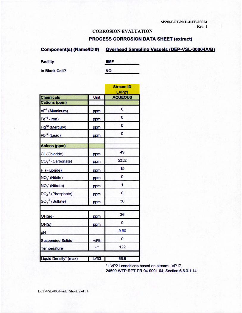
Component(s) (Name/ID #) Overhead Sampling Vessels (DEP-VSL-00004A/B)
Faclllty EMF ------In Black Cell? NO
Chemlcals Unit Cations (ppm)
Al•3 (Aluminum) oom
Fe+3 (Iron) DDm
Hg+2 (Mercury) oom
Pb+2 (Lead) DDm
Anions (oom)
er (Chloride) oom
co3•2 (Carbonate) ppm
F (Fluoride) DDm
NO2· (Nitrite) ppm
No3· (Nitrate) ppm
PO4 -3 (Phosphate) ppm
so4•2 (Sulfate) ppm
OH(aar DDm
OH(sr oom
IPH
Susoended Solids wt%
Temperature OF
Liquid Density* (max) lb/ft3 I
DEP-VSL-00004A/B: Sheet: 8 of 14
-Stream lD
LVP21 AQUEOUS
0
0
0
0
49
5352
15
0
1
0
30
36
0
9.50
0
122
68.6
* LVP21 conditions based on stream LVP17, 24590-WTP-RPT-PR-04-0001-04, Section 6.6.3.1.14

CORROSION EVALUATION
24590-BOF-Nl D-DEP-00004 Rev. I
24590-BOF-RPT-PR-15-001, Rev 0 Direct Feed LAW Process Corrosion Data
Figure A-7 DEP-VSL-00004A/B Aqueous PCDS
DDM Yma,,a.._.. S,aopoDl!od Solid. [wt '-l 0
T-1s.It.hn'-1 TBD
Som....~·r.-o TBD
hlati\, H;..,..li,y r,;.J • pH .00
ADl:i-F<»m;\pm [Ha] TBD
TOC(lml'la:) TBD
Pn.,,.., [p,q] TBD
T__,.[C] 62
y_,,__..(f] 143
u· .. s-Ra. fD-•m-J 1BD
T-1~ Flaw ha [llm!m] TBD
T-1Fi-:&.. [llm lbr) 1BD
~ E,--.pamcr c....i..a.
DEN-4
c--. Ar 0
,U..3 0
Am,,3 0 A:;+5 0
B+3 I
&+2 0
:s.+2 0 B,+3 0
C•+2 0
Cd+J 0
Ct+4 0
Co+2 0
Cr+3 0 Cr+6, 0
Co+ 0
Ca+2 0
&+3 0 , .... 1 0
Fo+3 0
H~ 0
H,+2 0
1:~ 0
i..+3 0
Ii+ I
Mr2 0
Mn+4 0
Mo+6 0 N.,.. I
Ncl+l 0
Nr+2 0 1'1,.,2 0 Pd+2 0 Pr-,4 0 P,,,,-4 0 b+2 0 RJ,... 0
Rlt+3 0 R.n+4 0 st,,,-3 0 So+4 0 Si+4 0 S.-.2 0 T>+.S 0 l'o+4 0 l'e-+4 0 Tu+4 0 Tt+4 0 TM , 0 ·-4 0
\+3 0 w~ 0 Y+3 0
Z-2 0 Zr+4 0
Aaieas B(OH)4- 0 ~2 0
Cl- 29 (N'.. 0
CO3-2 0 F- I
mJ>04. 0 H:?S.04-2 I H3Si04- I
HCOl- 0 HP04-2 0 HS03- 0 ~ I
I- 0 !03- 0
NH4'-- 0 002· 0 003- I
0-2 3 01-1 0
OH{>Q)- 0 OH{,)- 0 l'0'-3 0 S03-_ 0 ~2 l
0.-.... AIA_DC\IP 0 A.FA._NVOC 0
N\'OC' 0 Saa,yA 0 S\'OC' _2
'\,'O(' I
DEP-VSL-00004A/B: Sheet: 9 of 14
L\'?ll IIDtl
r•:1 0 1111 0 (I I 'DI) 11> TBD (111 'DI) 111 TBD (21 ... o.'• (l ) '"° 17)
9.50 (2.> 'DI) 11! TBD t2 ) 'DI) 111 TBD (21 0 ... 0 (! ) ,0 II) 5_ [? > 122 II) 116 (21 'DI) 111 TBD [l ) 'DI) 111 TBD [2> 'DI) 111 TBD
y......., 6:oml. VP-IX-I Tnmm hm. D£P-\ISL. 10 DEP-VS1.-4AIB 'IA.Ill 10 DEP-VSL-SA.IB
(2) L\,:1 (I) IIDtl ~--·---....., 0 0 0 0
0 0 0 0
0 0
0 0 0 0 0
0 0 0
0 0 0 0
0 0 0
0 0 0 0 0
0 0 .,. 1094
0 0 0 0 0 0 0 0 0 0 0 0 0 0 0 0 0 0 0 0 0 0 0 0 0 0
0 0 0 0
• l6 0 0
53S2 1473 lS 6
0 0 0 I 0 0 0 0 0 0 0 0 0 I 0 0 0 0
n, 74 0 0 l I 0 ? 0 0
(2 ) ,. (1lt 10
0 0 0 I 0
• 27
L_ .90 ____J 9
0 0 0 0 0 0 0 0 0 16 l I
(e
(1
(1
(1J
(1
(1) C•)
c•; c•;
(1)
(1)
(1)
IJt
(3)
LVP21
DEP04
Notes: (1) Values marked as "TBD" will be provided in the revision to 24590-BOF-M4C-V11T-00004 (Ref. 5.1.4(2)) based on APPS model runs for corrosion (2) DEP04 values from DEP-COND-00001/2/3 and DEP-FIL T-00004A/B PCDS reported in Figure A-5 including aqueous concentrations (3) Concentration values for DEP01 are the same as DEP20 (as shown in Figure A-8), since DEP01 is the only inlet stream to DEPVSL-OOOOSA/B included in the analysis from Ref. 5.1.4(2) (4) Maximum vessel property per 24590-BOF-MVC-DEP-00007 (Ref. 5.1.4(4), Section 8) (5) The solids concentration for the caustic scrubber effluent from LVP-TK-00001 is negtigible (Ref. 5.1.1(12), Section 6.6.3.2.1) (6) Suspended solids in DEP01 are negligible, due DEP04 and LVP21 both having negtigible suspended solids. (7) The maxirrun pH of DEP-VSL-00004A/B and DEP-VSL-OOO0SA/B on the PCDSs is 9.5, based on the pH range of 9 to 9.5 for caustic scrubber effluent provided in Ref. 5.1.1(12), Section 6.6.3.2.1 (8) Maximum temperature for stream LVP21 per Ref. 5.1.1(12), Section 6.6.3.2. 1 (9) Maximum concentrations of al COCs except OH(aq}- in governing stream LVP21 per Ref. 5.1.4(2) Table 8-5 (1 0) MINIMUM OH(aq)- value fOf governing stream L VP21 per Ref. 5.1.4(2) Table 8-5
GE.1/ER.AL _-,., DTE FOR USE OF PCDS:
• Tile hifor1t1atfo11 prn11ded by the PCDS 1-epon Is fnrended safely f or· rise /11 suppon of tl1e rnsse/ marl!lial selocrio11 pr0<.-ess ond C'ono.mm .Eval11ufions. T11e mp111s. ns.mmptions. and comp11taJ1onnl/e11gi11eeri11g models me.d 111 generating tlw results fH'esem,>d FH?n•m ar<> specific to this effort. Use of the n!fon ,iat,-011 presemed f,e,·em for any olher p inpose will requir« separarn co11sideration and c11ia~)•sis to $.ltppo,·t j11stif katio,i of irs use f o,. rh t> desired. almm nlfrc pu,posc.
• The p,"OCe. dc.scripti.ons i11 tllis rep<>n cowrr rourine pnx<>. opm·artonr mlC'I 11011-1-011rt" e (inft·eqmmr pron.>.ss operations, wli efl s11ch e.,isl, that co,Jd impact corrosion or erosion of proc:t>ss eqwpmem.
• The pt"OCeSS de.sc11prions pr'Ol'lded m rhts repo11 a,·e for gl!nl!ral i11forn1orio11 and n;,fll'rri,•,, of rhc ron-osto11 engmi'Cr 's analys-1s ftJr tm 11sparn11cy. the 111f o1111ano11 is curnmr 011ly m lhe time this docw11e11/ is iss11t.>d. These p,·~ d(!scrip1io11s should 1101 bo referenced/or design.

24590-BOF-NlD-DEP-00004 Rev. I
CORROSION EVALUATION
24590-BOF-RPT-PR-15-001, Rev 0 Direct Feed LAW Process Corrosion Data
4. 7 Onrhnd Sampling VHst-1s (DEP-VSL-00004A/B)
4.7.1 Dt-scliption ofVHttls
DEP-VSL-00004A/B recei\·e condensate from the evaporator. caustic scmbber fluids from the LAW L VP system. and stunp pump discharge from DEP-SUMP-00002AIB. DEP-SUMP-00004AtB. NLD-SUMP-00031. and NLD-SUMP-00032.
Overhead Sampling Vessel Transfer Pumps (DEP-PMP-00004AIB/C) are used to recirculate DEP-VSL-00004.AJB contents to a sample connection where samples are collected and fluid is returned to the tank through the eductors. Each batch is sampled and characterized before sending to the process condensate lag storage vessels (DEP-VSL-00005AiB). Off-spec condensate in DEP-VSL-00004AIB can be recycled to DEP-VSL-00002. In the event ofan overflow. the liquid will flow by gra\ity into DEP-VSL-00001.
The wssel contents can be sampled and the vessel are monitored for le,·el pressure. and temperature.
The Overhead Samplin!! Vessels are equipped \\ith Overhead Sampling Vessel :Mixing Eductors (DEPEDUC -00006/7 /8/9) to homogenize the contents and allow a representative sample to be taken.
DEP-VSL-00004AIB are passively purged with air drawn through the vessel head space and are vented to the Vessel Vent Header. Vessel vent streams are described in Section 4.10. This vessel \\ill haw capability to add process sen ice water (PS\V) for washing.
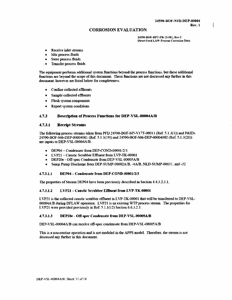
Figure 8 is a sketch of the input and output arrangement of streams for DEP-VSL-00004A1B.
Figure 8- DEP-VSL-00004A/B Sketch
CaUElit--flomLW-TK-00001
---•--
-----------1
' ~lo DEP-IISl.-00001
I I I I
1~---I l-----------lDEP01b)
4.7.2 System Functions
The process functions ofDEP-VSL-00004A/B are as follows:
DEP-VSL-00004A/B: Sheet: IO ofl4
Off-Req,delo DEP-VSL-00002
CORROSION EVALUATION
24590-BOF-NlD-DEP-00004 Rev.1
24590-BOF-RPT-PR-15-001, Rev 0 Direct Feed LAW Process Corrosion Data
• Receive inlet streams • Mix process fluids • Store process fluids • Transfer process fluids
The equipment performs additional system functions beyond the process ftmctions. but these additional functions are beyond the scope of this document. These functions are not discussed any further in this docUlllent. howe\·er are listed below for completeness.
• Confine collected effluents
• Sample collected effluents
• Flush system components
• Report system conditions
4.7.3
4.7.3.1
Dnc11ptton of PI·oct'ss Functions for DEP-VSL-00004A/B
Rttl'ipt Sh·Hms
The following process streams taken fromPFD 24590-BOF-M5-Vl7T-00011 (Ref. 5.1.3(1)) and P&IDs 24590-BOF-M6-DEP-00004001 (Ref. 5.1.3(19)) and 24590-BOF-M6-DEP-00004002 (Ref 5.1.3(20)) are inputs to DEP-VSL-00004AIB.
• DEP04 - Condensate from DEP-COND-00001/2/3 • LVP2 l - Caustic Scrubber Effluent from L VP-TK-00001 • DEP20e - Off-spec Condensate fromDEP-VSL-00005A'B • Sump Pump Discharge from DEP-SUMP-00002A'B. -4AiB. NLD-SUMP-00031. and -32
4.7.3.1.1 DEP04 - Condensate fl'om DEP-COND-00001/2/3
The properties of Stream DEP04 have been previously described in Section 4.4.3.2.3.1.
4.7.3.1.2 LVP21 - Caustic Scl'ubbel' Effluent from LVP-TK-00001
LVP21 is the collected caustic scrubber effluent in LVP-TK-00001 that will be transferred to DEP-VSL-00004A/B during DFLA W operation. L VP21 is an existing \\'lP process stream. The properties for LVP21 were provided previously in Ref. 5.1.1(12) Section 6.6.3.2.1.
4.7.3.1.3 DEP20e - Off-spec Condensate from DEP-VSL-00005A/B
DEP-VSL-00004A/B can receive off-spec condensate from DEP-VSL-00005AIB.
This is a non-routine operation and is not modeled in the APPS model. Therefore. the strean1 is not discussed any further in this document.
DEP-VSL-00004NB: Sheet: 11 ofl4

24590-BOF-NlD-DEP-00004 Rev.1
CORROSION EVALUATION
24590-BOF-RPT-PR-15-001, Rev 0 Direct Feed LAW Process Corrosion Data
4.7.3.1.4 Sump Pomp Disc.-baa-ge ft-om DEP-SL~IP-00002AIB. --4A/B, 1'"'LD-SL"YP-00031, and -32
DEP-VSL-00004A/B can receive the effluent from the sumps DEP-SUMP-00002AIB. DEP-SUMP-00004A/B.NLD-SUMP-00031. and NLD-SUMP-00032.
This is a non-routine operation and is not modeled in the APPS model. Therefore. the stream is not discussed any further in this docwnent.
4.7.3.2 Sto1·t- Liquid Efflut-nfs
DEP-VSL-00004A/B normally receives evaporator condensate and caustic scrubber effluent. The contents of the EMF utility room sump can also be received on a non-routine basis.
4.7.3.3 l\lix Liquid Efflut-nts
Mixing is accomplished in DEP-VSL-00004AIB using eductors (DEP-IDUC-00006/7/8/9) connected to a recirculation loop. Mixing helps provide a homogeneous mixture prior to sampling and transfer from the vessel.
4_7_3_4 Tl"ansfu P11>Ct'SS Fluids
The following process streams taken fromPFD 24590-BOF-M5-Vl7T-00011 (Ref. 5.1.3(1)) and P&ID 24590-BOF-M6-DEP-00004003 (Ref. 5.1.3(21)) are outputs from DEP-VSL-00004A/B.
• DEPOI - Transfer to DEP-VSL--00005A,,B • DEPOl b - Off-spec recycle to DEP-VSL-00002 • Overflow to DEP-VSL-00001
4.7.3.4.1 DEPOl - T1·ansfe1· to DEP-VSL-00005A/B
DEPO 1 is the main effluent from DEP-VSL-00004A'B transferred to DEP-VSL-00005A/B. which are lag storage vessels prior to transferring the condensate waste stream to LERF!ETF.
:Molalitv The minimum sodium molarity for DEPOl is OM based on the vessel inlet streams. DEP04 (Section 4.7.3.1.1) and L VP21 (Section 4.7.3.1.2). The range for sodium molarity in stream DEPOl during normal operations will be established in the DFLA W PIBOD.
Temperature The minimum. normal. and maximwn temperatures for stream DEPOl are 40cF. l 15cF. and 126°F respectively. based on the properties ofDEP-VSL-00004A'B (24590-BOF-MVC-DEP-00007. Section 8. Ref. 5.1.4(4)).
Solids Conc.-enh·ation The minimlllll solids concentration for DEPOI is 0 \\1 1!-'i, based on the vessel inlet streams. DEP04 (Section 4.7.3.1.1) and LVP21 (Section 4.7.3.1.2). The range for solids concentration in stream DEP0l during nomial operations will be established in the DFLA W PIBOD.
DEP-VSL-00004A/B: Sheet: 12 of14
CORROSION EVALUATION
24590-BOF-NlD-DEP-00004 Rev. I
24590-BOF-RPT-PR-15-001, Rev 0 Direct Feed LAW Process Corrosion Data
Denstn· The minimum. normal. andmaxinnun density for stream DEPOl is 61.6 lb/ft3, 63.5 lblft3. and 65.8 lb/ft3 respectively. based on the properties ofDEP-VSL-00004.A/B (Ref. 5.1.4(4). Section 8).
I!!! The range for pH in stream DEPOI during normal operations will be established in the DFLA W PIBOD.
4.7.3.4.2 DEPOlb - Off-sptt Rttyde to DEP-VSL-00002
If sampling shows the contents of DEP-VSL-00004.A/B do not meet the requirements for transfer to LERF/ETF. then the contents can be recycled to DEP-VSL-00002.
This stream is considered non-routine and is not modeled in APPS. Therefore. it will not be discussed further in this docmnent.
4.7.3.4.3 OnrOow to DEP-VSL-00001
DEP-VSL-00004A!B overflows through a gravity drain line that connects to the DEP vessel overflow collection header. ·which empties into DEP-VSL-0000 I . The vessel overflow is a non-routine condition that is not included in the APPS model and is not discussed ft1rther in this document.
4. 7.4 Process Modes
4. 7.4.1 Nonnal Operations
Based on the assessment of streams :frequently transferred in and out ofDEP-VSL-00004A-'B. the following processing modes are considered:
J11let streams: • DEP04 - Condensate from DEP-COND-00001/2/3 • LVP21-Caustic ScrubberEftluent:fromLVP-TK-00001
Outlet streams:
• DEPOl - Transfer to DEP-VSL-00005AlB
Section 4. 7. 5 .1 summarizes these processing modes in tabular foru1.
4.7.4.2 Infrequent Operations
Based on the assessment of streams infrequently transferred in and out ofDEP-VSL-00004AIB. the following processing modes are not considered:
J11let stre,(111/S: • DEP20e - Off-spec Condensate fromDEP-VSL-00005AIB • Smup Pump Discharge from DEP-SUMP-00002AIB. -4AIB. NLD-SUMP-00031. and -32
Outlet streams:
• DEPOla - Off-spec Recycle to DEP-VSL-00002
DEP-VSL-00004A/B: Sheet: 13 of14

24590-BOF-NtD-DEP-00004 Rev. 1
CORROSION EVALUATION
24590-BOF-RPT-PR-15-001, Rev 0 Direct Feed LAW Process Corrosion Data
• o,·erflow to DEP-\ SL-00001
4.7.5
4.7.5.1
Summary of Processing Conditions fo1· DEP-, SL-00004A/B
Normal Operations
The following table Stlllllnarizes the nom:ial process streams for DEP-\ SL-00004A/B.
Tablf' 4-10 - DI:P-VSL-00004A/B Nm·mal Opf'1·ations
Na :Molarity (mol/1.) T~fllff {°F) UDS(wf%)
L-0w Normal U er
0 0 0
LVP2 1 LVP21 propertil'S provided in Ref. 5.U(l2) Section 6.6.3 .2.1.
DEPOl 0 TBD TBD 40 HS 126 0 0
Note I - The maximum sooium molarity will be higher due to potential SM NaOH addition in this vessel for pH control.
DEP-VSL-00004A/B: Sheet: 14 of I 4
0