2.4.3. structuring sds normally a use case scenario is too long and complex to fit on a single (a4...
Post on 19-Dec-2015
214 views
TRANSCRIPT

2.4.3. Structuring SDsNormally a use case scenario is too long and
complex to fit on a single (A4 sized?) SD.
We need to structure SDs and decompose
them into
sub-SDs
called by
SD references.

A reference is a pointer to another SD.
References may not be circular or recursive.

Let us give a typical example. A simple dataexchange between two systems can be dividedinto 3 phases:
• set-up communication/initialize• exchange data• close-down communication
We can specify the use case “successful dataexchange” as follows.
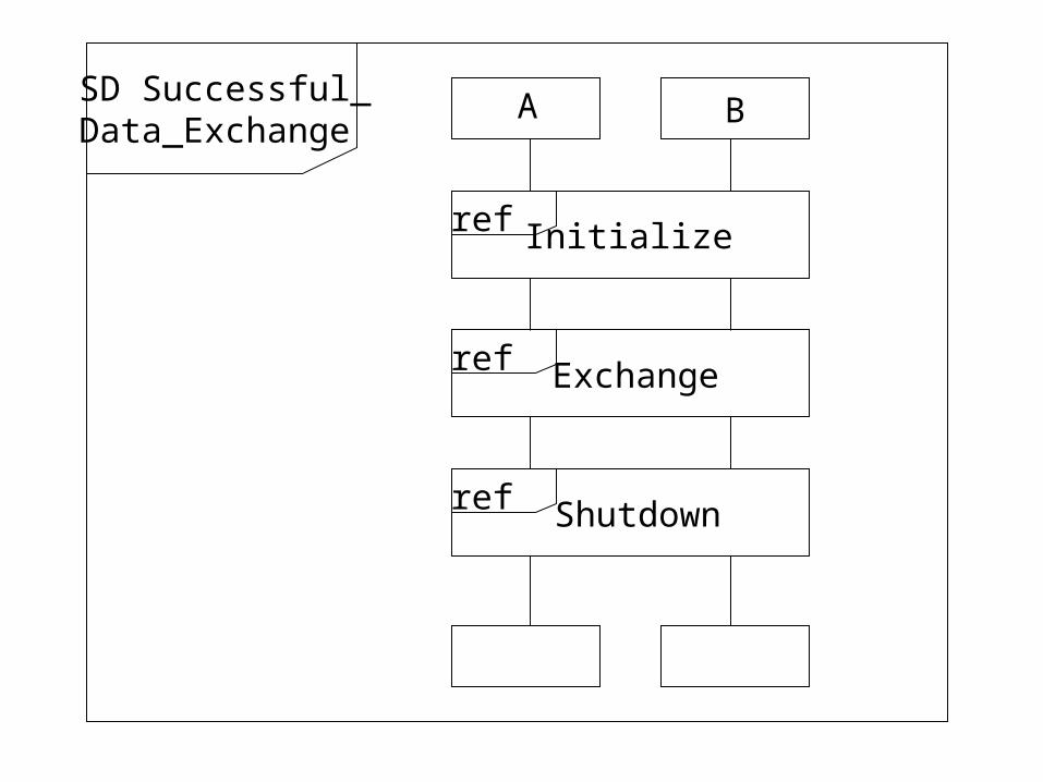
BA
Initialize
Exchange
Shutdown
SD Successful_Data_Exchange
ref
ref
ref

The symbol
denotes a sub-SD called name. Thus every
SD has a symbolic name also. The keyword
ref stand for reference.
Then for the above example, we might have:
<name>ref

BA A B
“ready_to_send”
“ready_to_receive”
“finished”
“shutdown”
SD Initialize SD Shutdown
Notice these are “handshakes” between A and B.
We will specify the SD “Exchange” later.

Note that a sub-SD does not synchronize
timelines.
i.e. either of A or B is free to leave sub-SD
Exchange without the other leaving
simultaneously.
Here’s another example to clarify the point.
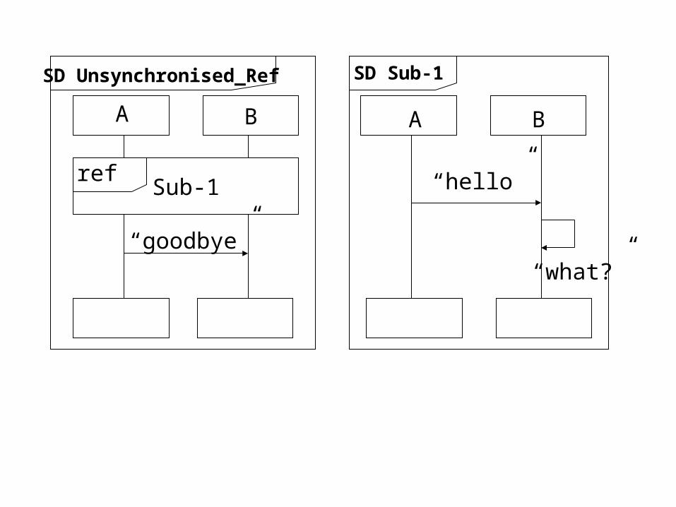
BA A B
“hello”
SD Unsynchronised_Ref SD Sub-1
“goodbye”
Sub-1
“what?”
ref

Possible executions are either:
1. hello
2. what
3. goodbye (A leaves Sub-1 late)
or
1. hello
2. goodbye (A leaves Sub-1 early)
3. what?

User System
“username”
“password?”
SD normal_log_in
“my_password”
Precondition: Power is on,
operating system is
active, log-in menu is visible.
Postcondition: Power is on, operating system is
active, user is logged in under own profile, user’s
desktop is visible, log-in menu is not visible.
UML comments

We introduce SD interaction operators
(In MSC language inline expressions)
• alt : alternative choice of sections
• par : parallel execution of several sections
• loop : iterative execution of a section
• opt : optional section that could be omitted
• (exc : exception section to handle errors.)

Interaction Operator alt
An operator (possibly with a Boolean guard)
used to define two or more alternatives, at
most one of which will be taken.
Below, Users u1 and u2 compete for the
Printer p.
Either u2 wins (top) or u1 wins (bottom)

u1 : User u2 : User p : Printer
SD Alternatives
“print_1”
“print_2”
alt “accept_2”
“accept_1”

The only possible executions or traces for SD
Alternatives are either :
1. print_1
2. print_2
3. accept_2
or
1. print_1
2. print_2
3. accept_1

Interaction Operator par
An operator used to define two or more sections, all of which will be executed simultaneously
Compare par with alt!
Below, u1 and u2 both request aprint job in parallel and both are accepted.

u1:User u2:User p:Printer
SD Parallel
par“accept_1”
“print_1”
“print_2”“accept_2”

This time there are 6 possible executions . These represent all possible interleavings of the two subsections of par.
1. print_1 1. print_1 1. print_2 1.print_12. print_2 2. accept_1 2. accept_2 2.print_23. accept_1 3. print_2 3. print_1 3.accept_24. accept_2 4. accept_2 4. accept_1 4.accept_1
1. print_2 1. print_22. print_1 2. print_13. accept_1 3. accept_24. accept_2 4. accept_1
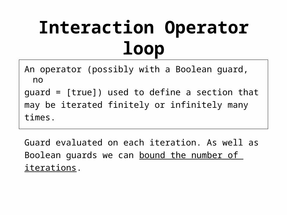
Interaction Operator loop
An operator (possibly with a Boolean guard, no
guard = [true]) used to define a section that
may be iterated finitely or infinitely many
times.
Guard evaluated on each iteration. As well as
Boolean guards we can bound the number of
iterations.

Keywords :(1) loop <m, n>, loop at least m times and at
most n times, for fixed integer constants m, n.
(2) loop <m, inf>, loop finitely often, but at least m times. ( *not* infinitely often).
(3) loop <inf, inf> loop at least infinitelymany times.
(4) loop <n> = loop <n, n> .(5) loop = loop <1, inf> .

Important note: The parameters m, n are
fixed constants, they are not variables which
can be changed.
In the following example, the user polls a
printer until the printer becomes ready.
When it becomes ready the printer prints
the file.

loop<0, inf>
alt “ready?”
“busy”
“ready?”
“ready?”
“yes”
“print(file)”
“printing”
u:User p:Printer

Interaction Operator Opt
An expression (possibly with a Boolean guard, noguard = [true]) used to define an optional sectionwhich may or may not be executed (non-deterministic).
In the next example, A sends to B and may or may not get confirmation before the next send.

opt “received”
“ok”
“send”
“send”
a:A b:B
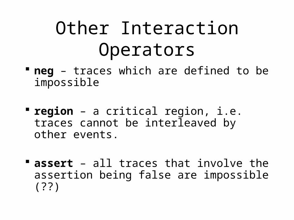
Other Interaction Operators
neg – traces which are defined to be impossible
region – a critical region, i.e. traces cannot be interleaved by other events.
assert – all traces that involve the assertion being false are impossible (??)

3. Object Models
3.1. Introduction
Object models capture the static structure of a
system, either by capturing:
• the class architecture, or
• the static object structure at some time
instant.
Both can be represented graphically.

3.2. Class diagrams
Class architectures lead to UML class diagrams which show:
• the template structure of a class,
• inheritance relations between classes,
• other relations.

A UML class diagram usually contains
essentially 2 kinds of information:
(1) The attributes and methods of a class,
perhaps with visibility constraints, typing information and initialisation values.
(2) The relations between classes, including
is_a and has_a.

3.2.1. Class Attributes
A class definition provides a template for
creating objects. This information includes:
• a class name,
• names and types of attributes,
• names and types of methods,
• initialization values at object creation time,
• visibility attributes of members.

<Name>
<attribute definition>*
<method definition>*

A class name is any string.
An attribute definition has the form
<name> [ : <type> ] [ = <initial value> ]
where the information in brackets
[ …]
is optional.
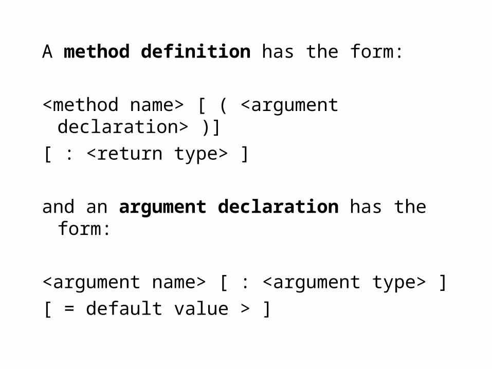
A method definition has the form:
<method name> [ ( <argument declaration> )]
[ : <return type> ]
and an argument declaration has the form:
<argument name> [ : <argument type> ]
[ = default value > ]
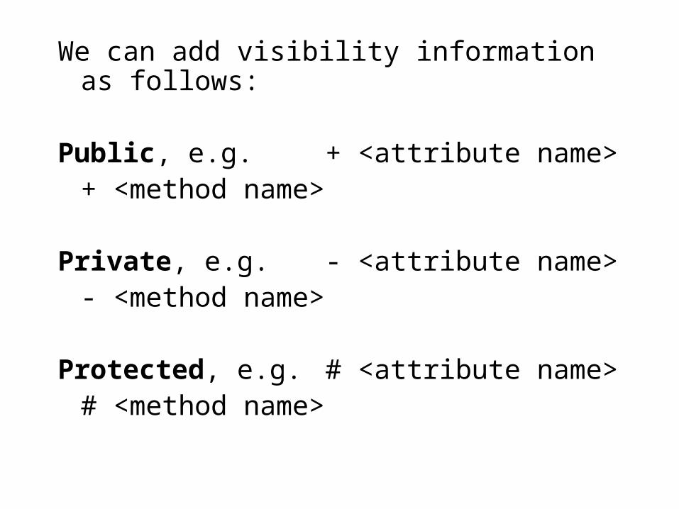
We can add visibility information as follows:
Public, e.g. + <attribute name>+ <method name>
Private, e.g. - <attribute name>- <method name>
Protected, e.g. # <attribute name># <method name>

3.2.2. Inheritance Information
After individual classes have been identified
by analysis as
Nouns
we try to identify inheritance relationships,
e.g. employee office manager
employee office worker

This will help us to:
• re-use code
• clarify definitions – is every x really a y ?– what’s the difference between x and y ?
• understand the structure of the domain
• spot incomplete models ( x ??? z )
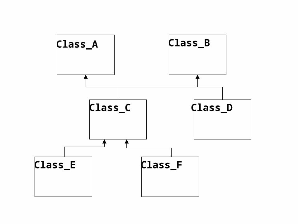
Class_A Class_B
Class_C Class_D
Class_E Class_F

class_C and class_D inherit from class_A.
class_C also inherits from class_B
(multiple inheritance, C++ but not Java)
Also class_E and class_F inherit from
Class_C. (So inheritance arrows may or
may not join up)

3.2.3. DiscriminatorsIt can be useful to explain the criterion which
determines inheritance and the subclasses.
Inheritance is a relation, and all relations can have
names which help us understand them.
Can regard as a meta-class = class of classes.
For example …

Figure
2_dim 3_dim1_dim
Line
Dimension
Dimension is an annotation onthe inheritance arrow.

3.2.4. Aggregation
Aggregation is an anti-symmetric and
transitive relation between two classes:
• a container class
• a component class.
The simplest example is class composition,
where one class is contained in another, e.g. ..

Book
Chapter
Section
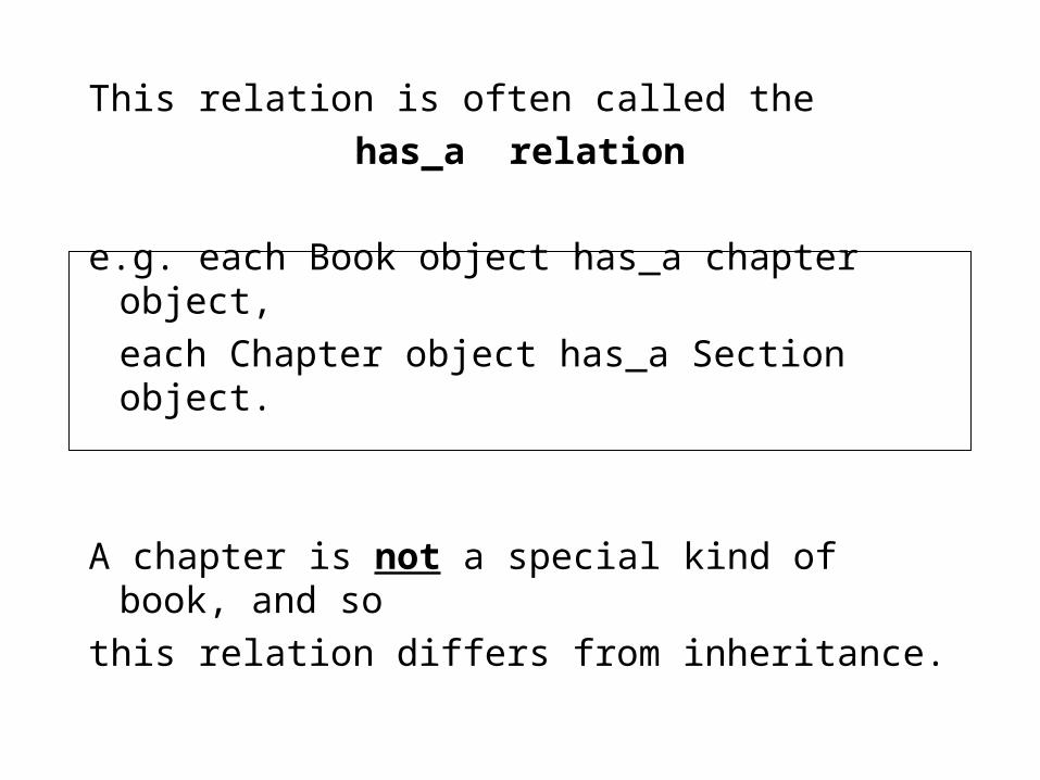
This relation is often called the
has_a relation
e.g. each Book object has_a chapter object,
each Chapter object has_a Section object.
A chapter is not a special kind of book, and so
this relation differs from inheritance.
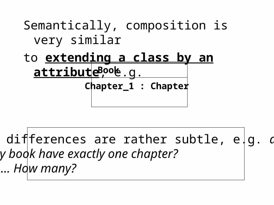
Semantically, composition is very similar
to extending a class by an attribute, e.g.
Book
Chapter_1 : Chapter
The differences are rather subtle, e.g. doesevery book have exactly one chapter?No? … How many?
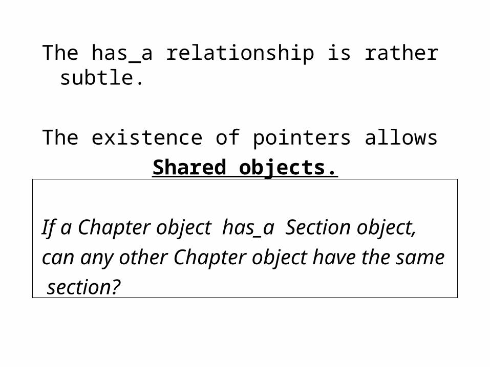
The has_a relationship is rather subtle.
The existence of pointers allows
Shared objects.
If a Chapter object has_a Section object,
can any other Chapter object have the same
section?
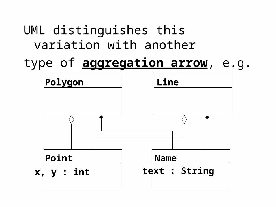
UML distinguishes this variation with another
type of aggregation arrow, e.g.
Polygon Line
Point Name
x, y : int text : String

A polygon and a line both have some points,which they can share with other polygons andlines. (e.g. by pointers).
Every polygon and line also has a namewhich should be unique and thereforeunshared.
In practice, the name might also beimplemented by pointers, so we must checkthe implementation really doesn’t share!

Notice that unshared has_a is a special case
of shared has_a ( the number of objects we
share with just happens to be one )
Thus it is often said that composition is a
special kind of aggregation.
When in doubt about sharing we can use
aggregation, can fill in diamond later!