24 using plc projects to aid teaching of advanced...
TRANSCRIPT
24
Using PLC Projects to Aid Teaching of Advanced Electrical Control Principles
by Wm. Ted Evans
Engineering Technology College of Engineering
U of Toledo Toledo, Ohio
Abstract A course in Programmable Controller Applications needs to concentrate the student's interests toward finding good employment. While accomplishing this task, the course or courses should also aid and strengthen the theoretical concepts taught in other coursework. The PID algorithm and other control blocks are good examples that may be used elsewhere. Several projects will be discussed. Structure of these projects leading the student from simple logic to difficult logic processes and their link to other coursework will be given. Introduction The two-course sequence presently taught at the University of Toledo's Engineering Technology Department's EET Program is designed to challenge PLC students and provide more well-prepared students for the manufacturing environment. The purpose of these courses is to provide programming experiences from the manufacturing environment. The first course concentrates on programming the PLC. A choice must be made for the PLC manufacturer and Allen-Bradley (A-B) was chosen [1-3]. Any course should look at the PLC generically with programming techniques taught that are common between different vendors. Allen-Bradley is a good choice for teaching the PLC but other vendors should be considered as the industry changes and matures. Laboratory experiences from the first course discussed include combinational logic labs, a binary add/subtract lab, a lab designed to implement a simple multiplexer and more sophisticated sequential logic labs including labs with substantially more rules. The second course uses the programming of the first course to control more sophisticated processes. The process may include a PID block or several PLCs communicating over a
Proceedings of the 2007 American Society for Engineering Education Annual Conference &Exposition Copyright © 2007, American Society for Engineering Education
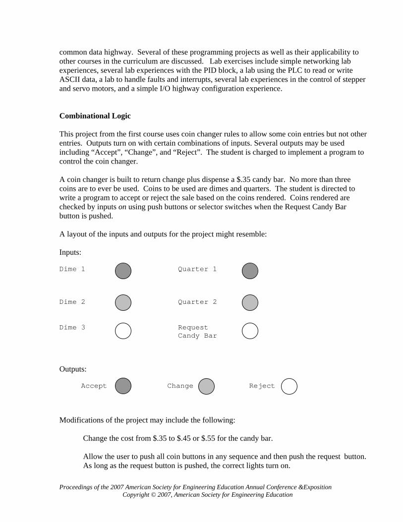
common data highway. Several of these programming projects as well as their applicability to other courses in the curriculum are discussed. Lab exercises include simple networking lab experiences, several lab experiences with the PID block, a lab using the PLC to read or write ASCII data, a lab to handle faults and interrupts, several lab experiences in the control of stepper and servo motors, and a simple I/O highway configuration experience. Combinational Logic This project from the first course uses coin changer rules to allow some coin entries but not other entries. Outputs turn on with certain combinations of inputs. Several outputs may be used including “Accept”, “Change”, and “Reject”. The student is charged to implement a program to control the coin changer. A coin changer is built to return change plus dispense a $.35 candy bar. No more than three coins are to ever be used. Coins to be used are dimes and quarters. The student is directed to write a program to accept or reject the sale based on the coins rendered. Coins rendered are checked by inputs on using push buttons or selector switches when the Request Candy Bar button is pushed. A layout of the inputs and outputs for the project might resemble: Inputs: Dime 1 Quarter 1 Dime 2 Quarter 2 Dime 3 Request Candy Bar Outputs: Accept Change Reject
Modifications of the project may include the following: Change the cost from $.35 to $.45 or $.55 for the candy bar. Allow the user to push all coin buttons in any sequence and then push the request button. As long as the request button is pushed, the correct lights turn on.
Proceedings of the 2007 American Society for Engineering Education Annual Conference &Exposition Copyright © 2007, American Society for Engineering Education
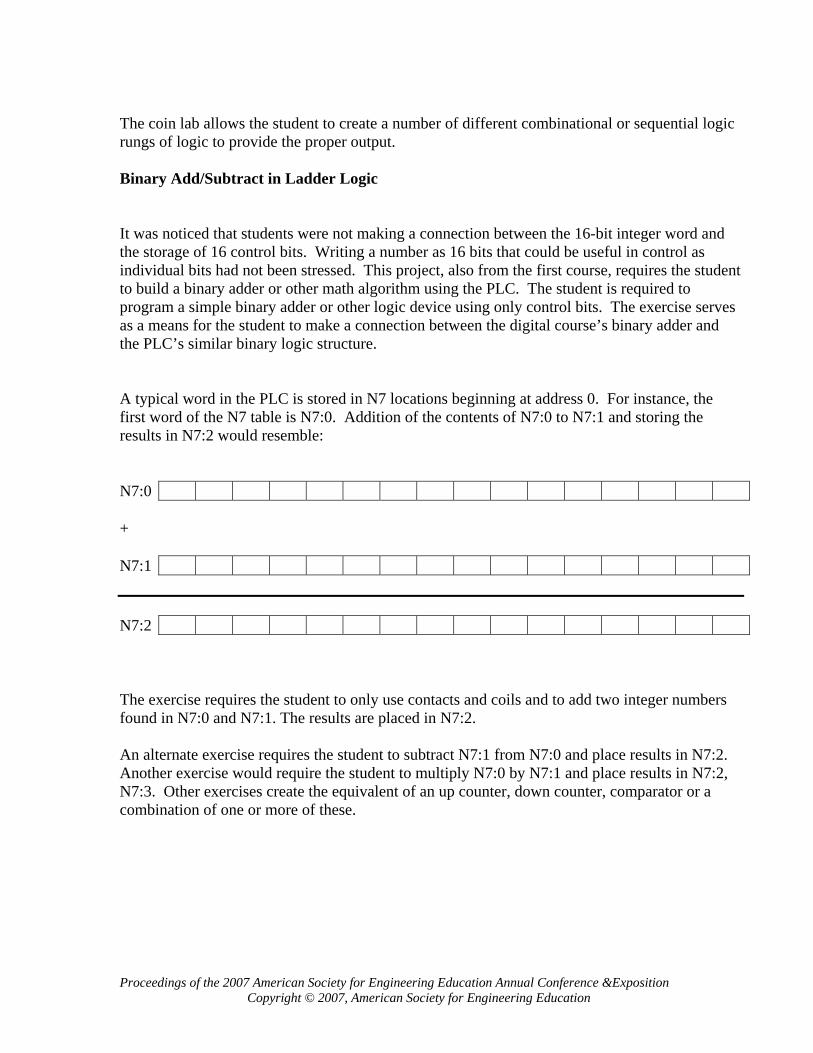
The coin lab allows the student to create a number of different combinational or sequential logic rungs of logic to provide the proper output. Binary Add/Subtract in Ladder Logic It was noticed that students were not making a connection between the 16-bit integer word and the storage of 16 control bits. Writing a number as 16 bits that could be useful in control as individual bits had not been stressed. This project, also from the first course, requires the student to build a binary adder or other math algorithm using the PLC. The student is required to program a simple binary adder or other logic device using only control bits. The exercise serves as a means for the student to make a connection between the digital course’s binary adder and the PLC’s similar binary logic structure. A typical word in the PLC is stored in N7 locations beginning at address 0. For instance, the first word of the N7 table is N7:0. Addition of the contents of N7:0 to N7:1 and storing the results in N7:2 would resemble: N7:0 + N7:1 N7:2 The exercise requires the student to only use contacts and coils and to add two integer numbers found in N7:0 and N7:1. The results are placed in N7:2. An alternate exercise requires the student to subtract N7:1 from N7:0 and place results in N7:2. Another exercise would require the student to multiply N7:0 by N7:1 and place results in N7:2, N7:3. Other exercises create the equivalent of an up counter, down counter, comparator or a combination of one or more of these.
Proceedings of the 2007 American Society for Engineering Education Annual Conference &Exposition Copyright © 2007, American Society for Engineering Education

The following example of ladder logic provides simple hints to the use of ladder logic for fundamental digital logic design. A Half Adder Designed with Ladder Logic: A B X - Output A B A B Carry where N7:0/0 = A N7:1/0 = B N7:2/0 = X - Output N7:3/1 = Carry While the first or right-most bit does not require a carry-in bit, all bits to the left require addition of the carry-in bit to determine the output and carry. A Full Adder Design with Ladder Logic: A B CarryIn X - Output A B CarryIn A B CarryIn A B CarryIn
Proceedings of the 2007 American Society for Engineering Education Annual Conference &Exposition Copyright © 2007, American Society for Engineering Education
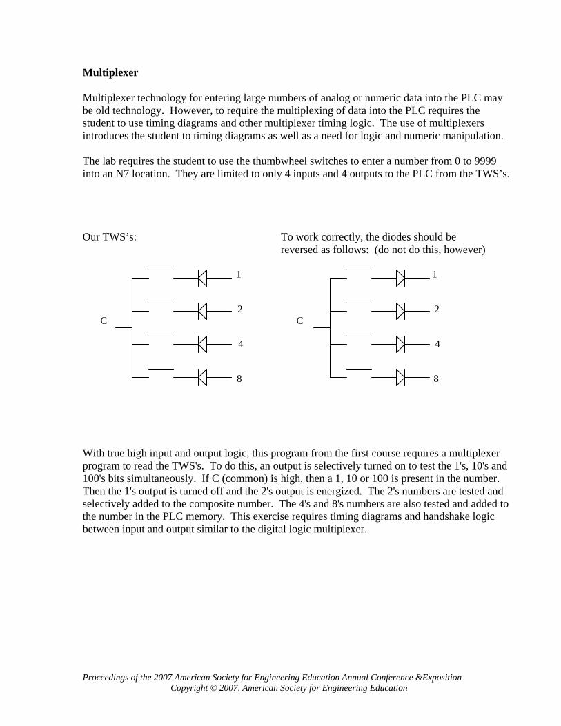
Multiplexer Multiplexer technology for entering large numbers of analog or numeric data into the PLC may be old technology. However, to require the multiplexing of data into the PLC requires the student to use timing diagrams and other multiplexer timing logic. The use of multiplexers introduces the student to timing diagrams as well as a need for logic and numeric manipulation. The lab requires the student to use the thumbwheel switches to enter a number from 0 to 9999 into an N7 location. They are limited to only 4 inputs and 4 outputs to the PLC from the TWS’s. Our TWS’s: To work correctly, the diodes should be reversed as follows: (do not do this, however) 1 1 2 2 C C 4 4 8 8 With true high input and output logic, this program from the first course requires a multiplexer program to read the TWS's. To do this, an output is selectively turned on to test the 1's, 10's and 100's bits simultaneously. If C (common) is high, then a 1, 10 or 100 is present in the number. Then the 1's output is turned off and the 2's output is energized. The 2's numbers are tested and selectively added to the composite number. The 4's and 8's numbers are also tested and added to the number in the PLC memory. This exercise requires timing diagrams and handshake logic between input and output similar to the digital logic multiplexer.
Proceedings of the 2007 American Society for Engineering Education Annual Conference &Exposition Copyright © 2007, American Society for Engineering Education

Sequential Logic The concept of sequential states using a counter is a necessary concept for the PLC programmer as well as the electronic designer to understand. The following program may be created to control the on-off control of three pumps.
Three Pumps: Three pumps are arranged as follows to provide cooling water for a manufacturing plant. For cooling to occur, at least one of the pumps must be on at all times but if no cooling is required, all pumps are to be turned off. For more cooling, a second pump is requested to turn on, followed by a third pump if sufficient cooling is still not received. To protect each from wearing out prematurely, a plan has been devised to allow each pump to turn on and off by using logic to turn on the next pump in sequence and turn off the pump that has been on the longest. Timers should not be used to determine the pump on longest but rather logic should be used to determine which pump should have been on the longest. For example, if pump 2 and 3 are on but 1 is off, pump 2 is the one that should be turned off since it probably came on before 3 did. If a call for less cooling is received and all three pumps are on, the pump that was logically on for the longest time should be turned off. The system starts out with no pumps on and when a call for more occurs, pump 1 will turn on. Then the system is cyclical rotating through pumps 2, 3, 1, 2, etc. More Pump 1 Less
Pump 2
Pump 3 A second program to require students to write concerning sequential logic might include: Write a program that turns on a light for 5 seconds when the operator pushes button 1, 2, 1, 2 in that sequencial order.
Proceedings of the 2007 American Society for Engineering Education Annual Conference &Exposition Copyright © 2007, American Society for Engineering Education
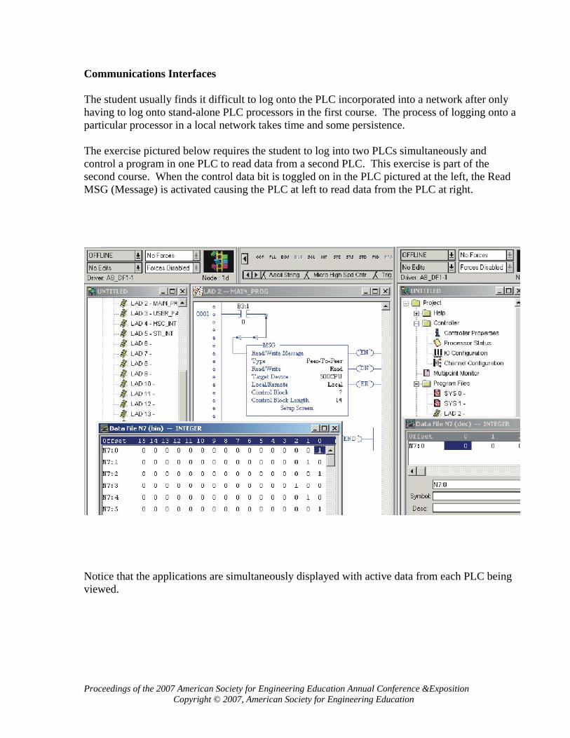
Communications Interfaces The student usually finds it difficult to log onto the PLC incorporated into a network after only having to log onto stand-alone PLC processors in the first course. The process of logging onto a particular processor in a local network takes time and some persistence. The exercise pictured below requires the student to log into two PLCs simultaneously and control a program in one PLC to read data from a second PLC. This exercise is part of the second course. When the control data bit is toggled on in the PLC pictured at the left, the Read MSG (Message) is activated causing the PLC at left to read data from the PLC at right.
Notice that the applications are simultaneously displayed with active data from each PLC being viewed.
Proceedings of the 2007 American Society for Engineering Education Annual Conference &Exposition Copyright © 2007, American Society for Engineering Education
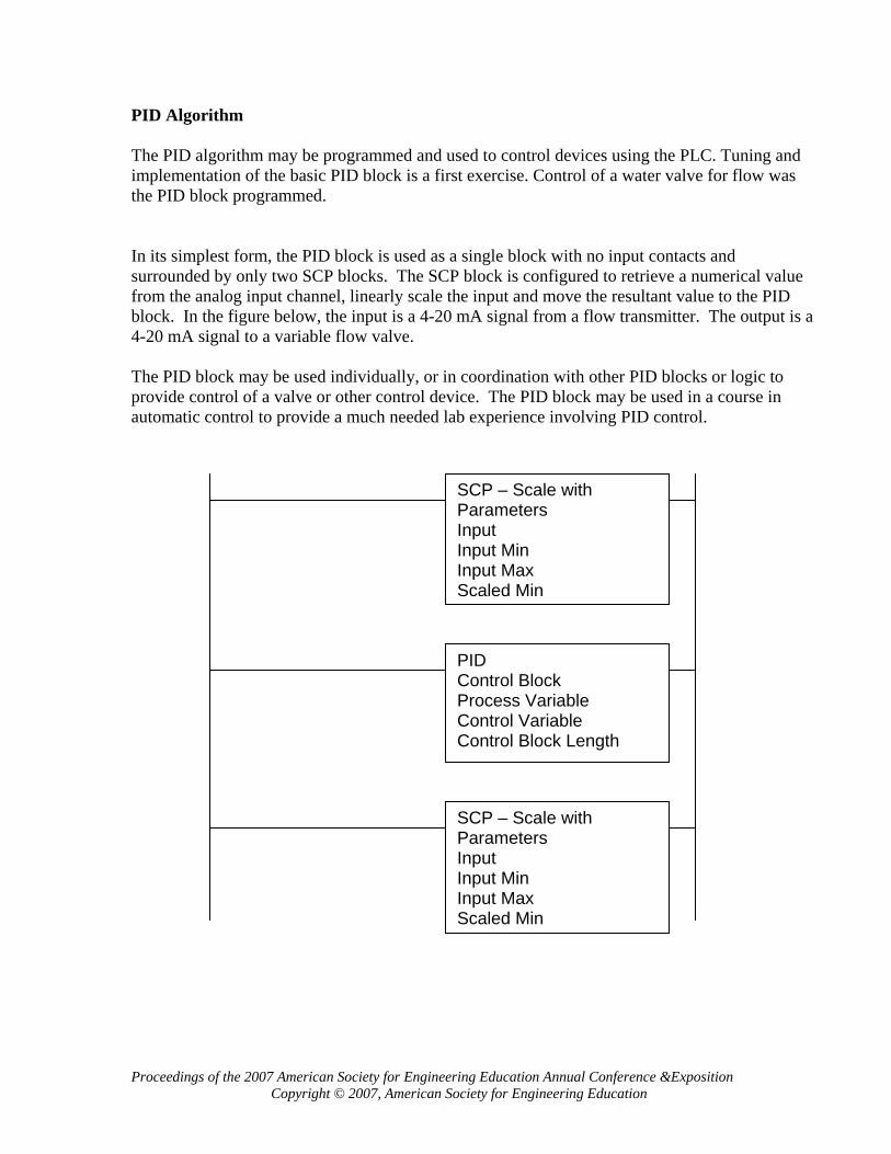
PID Algorithm The PID algorithm may be programmed and used to control devices using the PLC. Tuning and implementation of the basic PID block is a first exercise. Control of a water valve for flow was the PID block programmed. In its simplest form, the PID block is used as a single block with no input contacts and surrounded by only two SCP blocks. The SCP block is configured to retrieve a numerical value from the analog input channel, linearly scale the input and move the resultant value to the PID block. In the figure below, the input is a 4-20 mA signal from a flow transmitter. The output is a 4-20 mA signal to a variable flow valve. The PID block may be used individually, or in coordination with other PID blocks or logic to provide control of a valve or other control device. The PID block may be used in a course in automatic control to provide a much needed lab experience involving PID control.
SCP – Scale with Parameters Input Input Min Input Max Scaled Min
SCP – Scale with Parameters Input Input Min Input Max Scaled Min
PID Control Block Process Variable Control Variable Control Block Length
Proceedings of the 2007 American Society for Engineering Education Annual Conference &Exposition Copyright © 2007, American Society for Engineering Education

ASCII Read/Write Many devices such as bar code readers, weigh scales and RFID readers may use the ASCII read/write command blocks to communicate to the PLC. To test the read/write block, a computer is set up as a simple terminal for text transmission instead of a bar code reader or other serial communication device. The figure below demonstrates the PLC used as a communication device that can read or write an ASCII block to a second device.
The PLC may be used to write simple or complex protocols involving communications between computers as well and may be used to introduce the programming of protocols to the student.
Proceedings of the 2007 American Society for Engineering Education Annual Conference &Exposition Copyright © 2007, American Society for Engineering Education

Handling Faults and Interrupts To recover from a fault or to handle an interrupt requires the same type of command from the PLC. A lab experience to cause a fault and then recover from the fault is used to teach handling of interrupts. The lab purposefully causes a fault. The subsequent interrupt may be used to demonstrate the response of the CPU to an interrupt. The modern cpu handles interrupts through storage of data on the stack. If too many interrupts occur too quickly, the stack overflows and an error occurs. With the PLC, the stack is not used but data from the Status file is saved. Data saved includes:
- S:0 Arithmetic flags - S:13 and S:14 Math register - S:24 Index register
(S:x data represents data stored in the Status Table in 16 bit signed integer format.) The sequence of events is as follows:
Main Line Program Interrupt occurs: Interrupt ends, Executes through Prior values of: Main Line Program Rung 28. S:0, S:13, 14, S:24 saved begins execution at Program uses: Interrupt Program Begins rung 29 with restored S:0, New values of: values of: S:13, 14 S:0, S:13, 14, S:24 used S:0, S:13,14, S:24 S:24 Interrupt Program Ends
Proceedings of the 2007 American Society for Engineering Education Annual Conference &Exposition Copyright © 2007, American Society for Engineering Education

Stepper and Servo Motor Configuration The excitement of actually moving a device to an exact location is the object of this lab. Stepper motors may be configured manually using the data table of the stepper controller card to manually enter configuration and control information and move the stepper. The lab is enhanced when the HMI (Human Machine Interface) is programmed to enter the same information. After the stepper motor is configured successfully, the servo-motor may be assumed to be as easy to configure and run as the stepper motor. However, its configuration and control prove to not be as simple. With devices such as the servo, the student is pointed to the sample program of the appendix of the servo control user manual as a starting point to successfully control the device.
Configuration Word Layout: O:2.0 Config Output Word 0 O:2.1 Config Output Word 1 O:2.2 Config Output Word 2 O:2.3 Config Output Word 3 I:2.0 Config Input Word 0 I:2.1 Config Input Word 1 I:2.2 Config Input Word 2 I:2.3 Config Input Word 3
Proceedings of the 2007 American Society for Engineering Education Annual Conference &Exposition Copyright © 2007, American Society for Engineering Education

DeviceNet Configuration Data highways for sharing of data are a part of the modern PLC. DeviceNet is a simple I/O network that works well with most processors. Configuration of the network and using the network to control a simple PLC program is required[4]. DeviceNet uses the same chip-set as CanBUS. A network configured using DeviceNet is shown in the figure below.
Networks and Protocols It has become increasingly necessary for the PLC student to have a working knowledge of networks and network protocols. Setting up a network of PLCs and accompanying HMI computers should be the responsibility of the electrical engineer or engineering technologist. The establishment of a stable network is critical to the success of a project and should be addressed in a course such as this. Network security, while not necessarily a part of this course, should be addressed in the curriculum at some point.
Proceedings of the 2007 American Society for Engineering Education Annual Conference &Exposition Copyright © 2007, American Society for Engineering Education

Conclusion It was stated that a course in Programmable Controller Applications needs to concentrate the student's interests toward finding good employment. The course or courses should also aid and strengthen the theoretical concepts taught in other coursework. Several lab experiences were given to help develop the student in other areas of study as well as in preparation for the manufacturing world. The lab experiences parallel those encountered in other areas of study and may be useful to enhance lab experiences found elsewhere. Bibliography: [1] SLC Modular Processors, User Manual, Allen-Bradley [2] SLC 500 Instruction Set Reference Manual, Allen-Bradley [3] Logix5000 Quick Start Manual, Allen-Bradley [4] DeviceNet Starter Kit Installation Manual, Alley-Bradley Biography: Wm. Ted Evans is a professor of Engineering Technology at the University of Toledo. His educational background includes a BSEE in 1971 and MSEE in 1975. He receive the PhD in Industrial Engineering in May 2005. Mr. Evans was also a practicing Controls Electrical Engineer in industry for 15 years.
Proceedings of the 2007 American Society for Engineering Education Annual Conference &Exposition Copyright © 2007, American Society for Engineering Education