24 to 28 last
DESCRIPTION
TESTS AREVATRANSCRIPT

T&DAutomation & Information Systems - St Leonards Avenue – Stafford – ST17 4LX – England Tel: +44 (0)1785 223251 – Fax: +44 (0)1785 212232 AREVA T&D UK LTD. Registered Office: St Leonards Avenue – Stafford – ST17 4LX Registered in England: 4955841
P630 INTRODUCTION 2006 Page 1 of 71
Issue A.3 3 November 2006
PRACTICAL DEMONSTRATION:
MICOM P630 PROTECTION RELAYS
Location: Q:\P630_Tutorial\P630_intro.doc
OBJECTIVES: To gain familiarisation of the menu structure, the setting files and programmable scheme logic of the MiCOM PX30 relays
To provide a step by step guide to configuring and testing the differential function for a small transformer.

P630 INTRODUCTION Page 2 of 71Issue A. 3 November 2006
Table of Contents
1. INTRODUCTION.............................................................................................................41.1. SCOPE............................................................................................................................41.2. QUICK START: I NEED TO KNOW ................................................................................41.3. SECTION ABSTRACTS..................................................................................................4
2. LOCAL CONTROL .........................................................................................................52.1. FRONT PANEL ...............................................................................................................52.1.1. LCD & Keypad.................................................................................................................52.1.2. LED Indications ...............................................................................................................52.2. MENU STRUCTURE & NAVIGATION ............................................................................62.2.1. Structure – Top Level ......................................................................................................82.2.2. Structure - Parameters ....................................................................................................82.2.3. Structure - Operation.....................................................................................................102.2.4. Structure - Events..........................................................................................................112.3. MODIFYING PARAMETERS ........................................................................................122.3.1. Selecting Parameters ....................................................................................................122.3.2. Changing Parameters – Edit Mode ...............................................................................132.3.3. Default Condition: The Cold Restart..............................................................................142.3.4. Clearing the ‘Alarm’ LED ...............................................................................................152.3.5. Clearing the ‘Trip’ LED ..................................................................................................152.3.6. The ‘Out of Service’ LED...............................................................................................16
3. S&R-103 SETTING SOFTWARE..................................................................................173.1. COMMUNICATING WITH THE RELAY ........................................................................173.1.1. Connections ..................................................................................................................173.1.2. Launching the Software.................................................................................................173.1.3. Checking Communication Settings................................................................................173.2. IDENTIFICATION OF THE DEVICE .............................................................................183.3. SETTING FILE EXTRACTION ......................................................................................193.4. DATA MODEL EXTRACTION.......................................................................................203.5. MODULE IDENTIFICATION..........................................................................................213.6. MODIFYING PARAMETERS ........................................................................................223.6.1. Selecting Parameters ....................................................................................................223.6.2. Changing Parameters ...................................................................................................22
4. SETTING CONFIGURATION........................................................................................244.1. STARTING POINT ........................................................................................................244.2. ENABLING PROTECTION............................................................................................254.2.1. Select function from the available list of functions.........................................................254.2.2. Enable function from the selected functions..................................................................264.2.3. Enable master protection enable...................................................................................274.3. CONFIGURING OUTPUT RELAYS..............................................................................284.3.1. Mapping protection outputs as inputs to trip commands ...............................................294.3.2. Mapping trip command outputs to output relays............................................................304.3.3. *** Test Point 1 *** .........................................................................................................314.3.4. Minimum duration, latching and resetting of trip commands .........................................314.3.5. *** Test Point 2 *** .........................................................................................................324.3.6. Mapping the WATCHDOG contact................................................................................324.4. CONFIGURING OPTO-INPUTS ...................................................................................344.4.1. Mapping opto inputs as inputs to blocking commands..................................................354.4.2. Mapping blocking command outputs to function inputs.................................................36

P630 INTRODUCTION Page 3 of 71
Issue A. 3 November 2006
4.4.3. *** Test Point 3 *** .........................................................................................................364.5. CONFIGURING LEDS ..................................................................................................374.5.1. Mapping LEDs to function and command outputs.........................................................374.5.2. *** Test Point 4 *** .........................................................................................................38
5. SCHEME LOGIC...........................................................................................................395.1. PSL EDITOR .................................................................................................................395.2. CONFIGURING LOGIC.................................................................................................395.2.1. LOGIC Configuration.....................................................................................................405.2.2. Map an Opto-Input to a LOGIC input signal ..................................................................405.2.3. Map the LOGIC input signal into a LOGIC function.......................................................415.2.4. Mapping LOGIC function outputs to protection function inputs .....................................425.2.5. Mapping a LOGIC function output into a Trip Command ..............................................425.2.6. *** Test Point 5 *** .........................................................................................................435.2.7. Timer Stage – Pick-Up, Drop-Off and Duration .............................................................435.3. VERIFYING THE LOGIC...............................................................................................44
6. FAULT RECORDER .....................................................................................................456.1. CONFIGURING THE FAULT RECORDER...................................................................456.1.1. Configuring the read key ...............................................................................................466.2. EXTRACTION OF FAULT DATA ..................................................................................476.3. CLEARING FAULT RECORDS.....................................................................................486.3.1. Clearing Fault Records from the Display.......................................................................486.3.2. Clearing Fault Records from the Relay Memory ...........................................................48
7. OPERATION, OVERLOAD AND FAULT PANEL........................................................497.1. THE OPERATION PANEL (DISPLAYING MEASURMENTS) ......................................497.2. THE OVERLOAD PANEL..............................................................................................507.3. THE FAULT PANEL (DISPLAYING FAULT MEASURMENTS)....................................51
8. CONFIGURATION OF CYCLIC MEASUREMENTS ....................................................52
9. FILE COMPARISON AND CONVERSION...................................................................549.1. FILE COMPARISON .....................................................................................................549.2. FILE CONVERSION......................................................................................................55
10. CONFIGURATION AND TEST OF A DIFFERENTIAL PROTECTION SCHEME........5810.1. SETTING THE ‘DIFF’ PROTECTION SCHEME ...........................................................5810.1.1. Enable the DIFF function...............................................................................................5810.1.2. System & Transformer Parameters ...............................................................................5910.1.3. CT and VT Ratios..........................................................................................................5910.1.4. Differential Settings .......................................................................................................5910.1.5. Configure the Trip Commands ......................................................................................6010.1.6. Configure an Output Trip Relay, LEDs & Watchdog Contact ........................................6010.1.7. Configure the Fault Recorder and the Operation & Fault Pages...................................6010.2. TESTING THE DIFFERENTIAL BIAS CHARACTERISTIC ..........................................6110.2.1. Reference Currents and CT Matching Factors..............................................................6110.2.2. Spot Testing the Relay Settings ....................................................................................6310.2.3. Testing the Differential Characteristic using Harmonised Relay Settings .....................66
11. MISCELLANEOUS .......................................................................................................6911.1. ZERO SEQUENCE FILTERING....................................................................................6911.2. VECTOR GROUP MATCHING FACTORS...................................................................70

P630 INTRODUCTION Page 4 of 71Issue A. 3 November 2006
1. INTRODUCTION Protection devices in the MiCOM 30 Series are described in detail in the respective technical manuals, as regards their technical merits, functional characteristics, and handling during installation, connection, commissioning, and operation.
However, the technical manuals are very comprehensive due to the innumerable features of MiCOM 30 Series devices. Unfamiliar users may have a hard time with learning how to operate a device.
1.1. SCOPE This document is intended to help those users get started. The intention is to accompany the user through the initial stages of communication and setting support.
By learning those basic operating procedures, it is hoped that the user will be able to continue in confidence, using the full technical manual for reference and this document for support.
1.2. QUICK START: I NEED TO KNOW ‘I have never used a Px30 relay’: Start at the beginning and work though the whole document.
’I have used Px30 relays before, but not the P630 range’: Start at section 10, which will help you configure and test the differential function. Use the rest of the document for reference.
‘I don’t have the communications software, but I want to change some settings’: Section 2describes operation via the relay front panel. Your ability to make more than trivial changes will be limited.
‘The P63x relay is already set-up I just want to test it’: Start at section 10.2, which will guide you through the test procedure.
‘What data model is my relay’: See sections 3.2 and 9.2 to determine what the relay model and data model is, or look under the flap on the front of the relay.
1.3. SECTION ABSTRACTS The following is an abstract of each of the following chapters:
Section 2: Details the local control of the Px30 relay, the menu structure and navigation and how to modify parameters via the relay front panel.
Section 3: Details the communication and setting support software. Explains how to communicate with the relay and change parameters via the communication port.
Section 4: Step by step guide on setting up a protection function (IDMT1), including opto input, output relay and scheme logic assignments.
Section 5: The use and operation of the Scheme Logic feature. Configuring an intertrip signal is used as an example.
Section 6: Explains the configuration of the Fault Recorder, including the extraction and deletion of fault records.
Section 7: How to set up the default relay display panel, by configuration of the Operation, Overload and Fault panels.
Section 8: Use of Cyclic Measurements through the setting software. Section 9: The setting file utilities of comparison and conversion, which enable setting files to
be converted to different data models and comparisons made between setting files. Section 10: Step by step guide to configuring and testing the Differential function by applying it
to a small transformer. Section 11: Miscellaneous information.

P630 INTRODUCTION Page 5 of 71
Issue A. 3 November 2006
2. LOCAL CONTROL
2.1. FRONT PANEL The front plate of the relay is as shown in Figure 2-1.
2.1.1. LCD & Keypad
20-character by 4-line alphanumeric liquid crystal display (LCD)
7-key keypad comprising 4 arrow keys ( , , and ),an enter key ( ), a clear key ( ), and a read key ( ).
17 LED’s; 4 fixed function LED’s on the left-hand side of the front panel and 13 programmable function LED’s.
A 9-pin female D-type front port for communicating with a PC locally to the relay (up to 15m distance) via an EIA (RS) 232 serial data connection.
2.1.2. LED Indications
Trip LED (Red) - This indicates that the relay has issued a trip signal. It is reset when the fault is removed from the relay and the front panel cleared.
Alarm LED (Yellow) - Flashes to indicate that the relay has registered an alarm. It is reset when the associated alarm is cleared from the relay.
Out of service (Yellow) - Indicates the relay protection is not active, either the relay has had its protection disabled or there are communications in progress.
Healthy (Green) - Indicates that the relay is in correct working order, and should be on at all times. It will be extinguished if the relay’s self-test facilities indicate that there is an error with the relay’s hardware or software. This indication is also available via a dedicated watchdog output relay.
Edit Mode (Red) - The relay settings are being modified via the front panel.
Figure 2-1 Relay Front Panel
GGC
GG
G
G
G
TRIP
ALARM
OUT OF SERVICE
HEALTHY
EDIT
= CLEAR
= ENTER
= READ
C
MiCOM
H4H3H2H1H0
H5H6H7H8H9H10H11H12H13H14H15H16

P630 INTRODUCTION Page 6 of 71Issue A. 3 November 2006
2.2. MENU STRUCTURE & NAVIGATION The menu structure of the Px30 incorporates a comprehensive package of individual functions, in order to permit an extensive and universal scope of application. This results in a huge number of data points (setting values, signals, measured values, etc.) which are arranged in two ways.
Function Groups:
All data points are grouped into function groups according to the function they are associated with. These groups have an related acronym for example MAIN, DIFF, IDMT etc...
Folders/Branches:
The data points within the function groups, are organised into different folders, based on the logical control requirements. Folders can contain data points from a variety of function groups.
For a typical protection function, for example IDMT1 (over current protection 1), data points associated with the IDMT1 function group may appear in many folders, dependant on the logical nature of that setting. For example a configure parameter will appear in a different folder to a time delay setting. It is the layout of these folders that forms the menu tree.
The description of all data points in this menu tree, is called the data model.The values associated with each data point, is called the settings file.
To logically view a settings file you need the data model. Fortunately this can be extracted from the relay directly, if it is not available in the setting software, see section 3.4.
The menu tree begins with the device type at the top and then branches out below into the three main folders entitled, Parameters, Operation and Events, which form the first folder level. Below this first folder level are two more folder levels, so that the entire folder structure consists of three main branches and a maximum of three folder levels. After this the logical structure falls naturally into the function groups, which forms the lowest logical organisation of data points.
This structure is shown in Figure 2-2.

P630 INTRODUCTION Page 7 of 71
Issue A. 3 November 2006
Figure 2-2 Front Panel Menu Structure
P630 INTRODUCTION Page 8 of 71Issue A. 3 November 2006
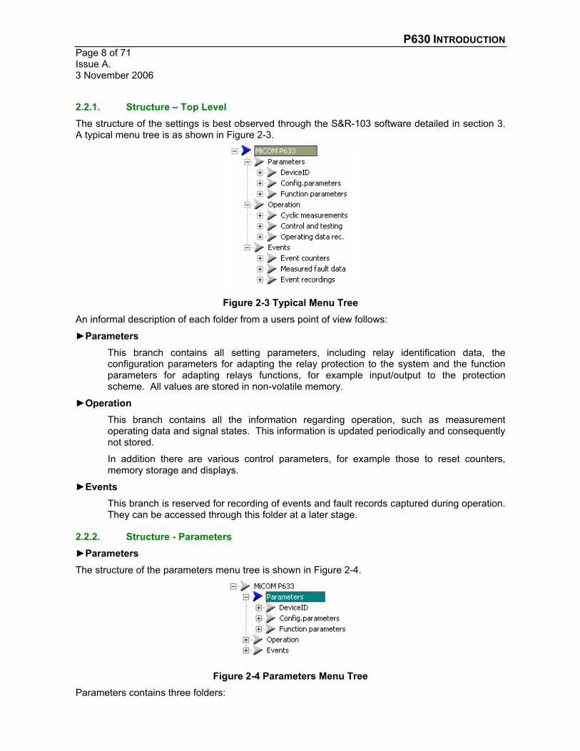
2.2.1. Structure – Top Level The structure of the settings is best observed through the S&R-103 software detailed in section 3.A typical menu tree is as shown in Figure 2-3.
Figure 2-3 Typical Menu Tree An informal description of each folder from a users point of view follows:
Parameters This branch contains all setting parameters, including relay identification data, the configuration parameters for adapting the relay protection to the system and the function parameters for adapting relays functions, for example input/output to the protection scheme. All values are stored in non-volatile memory.
Operation This branch contains all the information regarding operation, such as measurement operating data and signal states. This information is updated periodically and consequently not stored.
In addition there are various control parameters, for example those to reset counters, memory storage and displays.
EventsThis branch is reserved for recording of events and fault records captured during operation. They can be accessed through this folder at a later stage.
2.2.2. Structure - Parameters Parameters
The structure of the parameters menu tree is shown in Figure 2-4.
Figure 2-4 Parameters Menu Tree Parameters contains three folders:

P630 INTRODUCTION Page 9 of 71
Issue A. 3 November 2006
DeviceIDThis branch contains all the information regarding the relay type and version , for example software, language and hardware versions.
Config.parameters This branch contains two types of ‘settings’, contained within individual function groups.
i. Settings to enable configuration of relay I/O, comms and the fault recorder.
ii. A complete list of protection and control functions that contain a single configuration status that can be enabled or disabled. This makes the corresponding settings for that function visible in the Function parameters General functions branch.
Function parameters The menu structure of this branch is shown in Figure 2-5.
Figure 2-5 Function parameters Menu Tree Function parameters contains six folders:
GlobalThis branch contains settings that act upon all enabled control or protection functions.
General functions This branch contains all the enabled functions configured in the Config.parameters branch. The settings available are presented in function groups and are the common settings for the functions presented in each Parameter subset X1.
Parameter subset X1
These branches contain the subset (setting group) specific function settings. This enables functions to be configured differently for each subset.
1 X represents the subset number.

P630 INTRODUCTION Page 10 of 71Issue A. 3 November 2006
2.2.3. Structure - Operation Operation
The structure of the operation menu tree is shown in Figure 2-6.
Figure 2-6 Operation Menu Tree Operation contains three folders:
Cyclic measurements The menu structure for this branch is shown in Figure 2-7.
Figure 2-7 Cyclic measurements Menu Tree Cyclic measurements contains three folders:
Meas.operating dataThis branch contains the measurements that are taken by the relay. As more protection functions are enabled, then any bespoke protection measurements become available (organised in their function groups).
Phys. state signalsThis branch contains the state of all the physical signals that are present in the relay. This can be hardware dependant but will consist (as a minimum) of LEDs, inputs and outputs.
Log. state signalsThis branch contains the logical signal states. This consists of for example, the state of the blocking inputs to the enabled protections and command inputs to the general relay control functions. The list becomes greater as more functions are enabled.
Control and testingThis branch contains settings that allow the control and testing of certain functions. For example the testing of individual output relays and the control of the event recording (i.e. resetting/deleting).
Operating data rec.This branch displays the condition of the monitoring and operating data recorders.
P630 INTRODUCTION Page 11 of 71
Issue A. 3 November 2006
2.2.4. Structure - Events Events
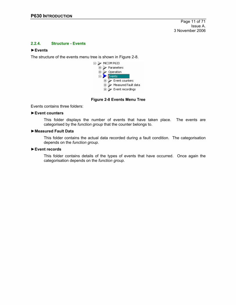
The structure of the events menu tree is shown in Figure 2-8.
Figure 2-8 Events Menu Tree Events contains three folders:
Event countersThis folder displays the number of events that have taken place. The events are categorised by the function group that the counter belongs to.
Measured Fault DataThis folder contains the actual data recorded during a fault condition. The categorisation depends on the function group.
Event recordsThis folder contains details of the types of events that have occurred. Once again the categorisation depends on the function group.

P630 INTRODUCTION Page 12 of 71Issue A. 3 November 2006
2.3. MODIFYING PARAMETERS This section details the process of selecting and changing parameters and contains some useful functions that users may want to undertake.
2.3.1. Selecting Parameters All data points (setting values, signals, measured values, etc.) are selected using the menu tree. As the user navigates through the menu tree, the first two lines of the LCD display always show the branch of the menu tree that is active, as selected by the user.
The data points are accessed at the lowest level of a menu tree branch. They are displayed with their plain text description. The value associated with the selected data point, its meaning, and their units of measurement are displayed in the line below.
The desired parameter (e.g. ‘MiCOM Px3x/Parameters/Config.paramters/LOC/Decimal delimiter’) can be selected by pressing the keys ‘Left’, ‘Right’, ‘Up’ and ‘Down’:
Note: In the case that the scrolling default is displayed, please press the ENTER key first in order to access the menu tree.
Note: If the display text is not present and numerical cell references are visible then press, the CLEAR key and the LEFT ARROW together to change the display mode.
MiCOM Px3x
MiCOM Px3xParameters
Par/Device ID
Par/Config.parameters
Par/Conf/LOC
Par/Conf/LOCLanguage (tongue)English
Par/Conf/LOCDecimal delimiterdot
Figure 2-9 Selecting Parameters

P630 INTRODUCTION Page 13 of 71
Issue A. 3 November 2006
2.3.2. Changing Parameters – Edit Mode
Although it is possible to select any data point in the menu tree and read the associated value by pressing the keys, it is not possible to switch directly to the ‘Edit’ mode. This safeguard prevents unintended changes in the settings. To access edit mode the password has to be entered.
Changing a parameter (e.g. ‘MiCOM Px3x/Parameters/Config.paramters/LOC/Decimal delimiter’):
Note: Edit mode can be left without changing a parameter by pressing the CLEAR key instead of the ENTER key.
Par/Conf/LOCDecimal delimiterDot
Par/Conf/LOCDecimal delimiterDot********
Par/Conf/LOCDecimal delimiterDot
Par/Conf/LOCDecimal delimiterComma
Par/Konf/VOBDecimal delimiterComma
Enter the passwordand confirm
Enter the input mode
Change the parameter value
Leave the input modeby accepting the change
Figure 2-10 Changing Parameters

P630 INTRODUCTION Page 14 of 71Issue A. 3 November 2006
2.3.3. Default Condition: The Cold Restart The actual settings status is difficult for the user to quickly establish and this can cause problems. It is often easier to restore the relay to its default condition; this is achieved via a cold restart.
Prior to initialising a cold restart, ensure that the device protection is disabled.
(‘MiCOM Px3x/Parameters/Function.parmeters/Global/MAIN/Protection enabled’):
Par/Func/Glob/MAINProtection enabledNo (=off)
If the device is disabled, a cold restart can be initialised
(‘MiCOM Px3x/Operation/Control and Testing/MAIN/Cold restart’):
Oper/CrtlTest/MAINCold restartdon't execute
Change the value to ‘execute’ by the procedure described in section 2.3.2.
Oper/CrtlTest/MAINCold restartexecute
Then press the ENTER key and the device will reboot:
************************ REBOOT *********************************************
TEST>>>>>>>>
After a cold restart any non default settings have been deleted and all records have been cleared. All parameters are set to their default value.

P630 INTRODUCTION Page 15 of 71
Issue A. 3 November 2006
2.3.4. Clearing the ‘Alarm’ LED Once the relay has rebooted, the Alarm LED will be ‘on’, this is because of the deliberate distortion of the parameter checksum, which has been used to initiate the desired cold restart.
To clear the alarm the corresponding entry has to be readout of the monitoring signal memory. (MiCOM Px3x/Operation/Operating data rec./MT_RC/Mon. signal record.’):
Mon. signal record.01.01.97 08:43 SFMONChecksum error param
Oper/Rec/MT_RCMon. signal record.
Mon. signal record.01.01.97 08:43 SFMONCold restart
In order to switch off the ALARM LED, clear the monitoring signal memory. (‘MiCOM Px3x/Operation/Control and Testing/MT_RC/Reset recording’):
Oper/CrtlTest/MT_RCReset recording 2
Change the value to ‘execute’ by the procedure described in section 2.3.2.
Oper/CrtlTest/MT_RCReset recording 2execute
Press the ENTER key. The number of entries in the monitoring signal memory will be changed to ‘0’ and the ALARM LED will go ‘off’:
Oper/CrtlTest/MT_RCReset recording 0
2.3.5. Clearing the ‘Trip’ LED If the relay has tripped, the Trip LED will be ‘on’. If the fault condition is still present, the LED will remain illuminated. However if the fault condition is no longer applied, then the trip LED can be reset by clearing the display. Press the CLEAR key twice, at the default display.
If you are having difficulty with the default display once a trip has occurred, refer to section 6.3.1.

P630 INTRODUCTION Page 16 of 71Issue A. 3 November 2006
2.3.6. The ‘Out of Service’ LED After a reboot of the relay the ‘Out of Service’ LED may be on. In order to switch off the LED and return the relay to an enabled state. The corresponding parameter has to be modified.
(MiCOM Px3x/Parameters/Function.parameters/Global/Main’):
Par/Func/Glob/MAINProtection enabledYes (=on)
Note: The ‘Out of Service’ LED, may occur for the following reasons there have to be corrected before the LED can be extinguished.
i. Output relays must not be blocked:
Par/Func/Glob/OUTPOutp.rel.block USERNo
ii. The device must be enabled generally as described above:
Par/Func/Glob/MAINProtection enabledYes (=on)
iii. Trip commands may not be blocked:
Par/Func/Glob/MAINTrip cmd.block. USERNo
The ‘Out of Service’ LED may occur due to the self-monitoring function, which has detected an internal fault of the device. In that case the ALARM LED is also energised. Readout the corresponding entries in the monitoring signal memory, as described in section 2.3.4 and rectify the situation.
P630 INTRODUCTION Page 17 of 71
Issue A. 3 November 2006
3. S&R-103 SETTING SOFTWARE MiCOM Px30 series devices can be operated via the S&R-103 software, within the MiCOM S1 suite of software.
3.1. COMMUNICATING WITH THE RELAY
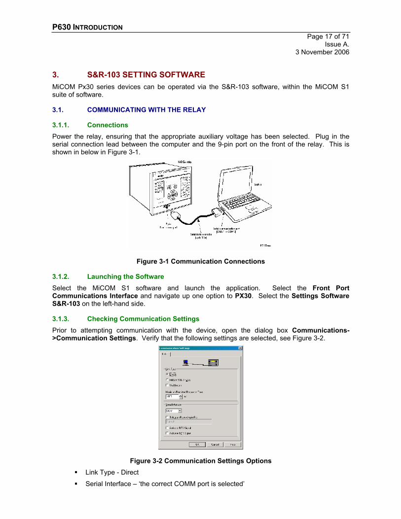
3.1.1. Connections Power the relay, ensuring that the appropriate auxiliary voltage has been selected. Plug in the serial connection lead between the computer and the 9-pin port on the front of the relay. This is shown in below in Figure 3-1.
Figure 3-1 Communication Connections
3.1.2. Launching the Software Select the MiCOM S1 software and launch the application. Select the Front Port Communications Interface and navigate up one option to PX30. Select the Settings Software S&R-103 on the left-hand side.
3.1.3. Checking Communication Settings Prior to attempting communication with the device, open the dialog box Communications->Communication Settings. Verify that the following settings are selected, see Figure 3-2.
Figure 3-2 Communication Settings Options Link Type - Direct
Serial Interface – ‘the correct COMM port is selected’

P630 INTRODUCTION Page 18 of 71Issue A. 3 November 2006
3.2. IDENTIFICATION OF THE DEVICE To commence communications with the relay, open the dialog box Communications->Identify Device, shown in Figure 3-3.
Figure 3-3 Identify Device Ensure that the settings of Baud Rate, Bay Address and Parity are equal to the settings of the device. Also verify that the following configuration parameters on the relay are as follows, if communication cannot be established.
Par/Conf/PCName of manufacturerALSTOM D
Par/Conf/PCBay address 1
Par/Conf/PCDevice address 1
Par/Conf/PCBaud rate19.2 kBaud
Par/Conf/PCParity bitEven
Par/Conf/PCSpontan. sig. enableNone
Par/Conf/PCTransm.enab.cycl.datWithout
Once these settings have been confirmed press the Identify button and the S&R-103 will start communicating with the relay. The S&R-103 will scan each baud rate looking for the relay.
If communication is successful, the following screen shown in Figure 3-4 will be displayed.
P630 INTRODUCTION Page 19 of 71
Issue A. 3 November 2006
Figure 3-4 About the Device
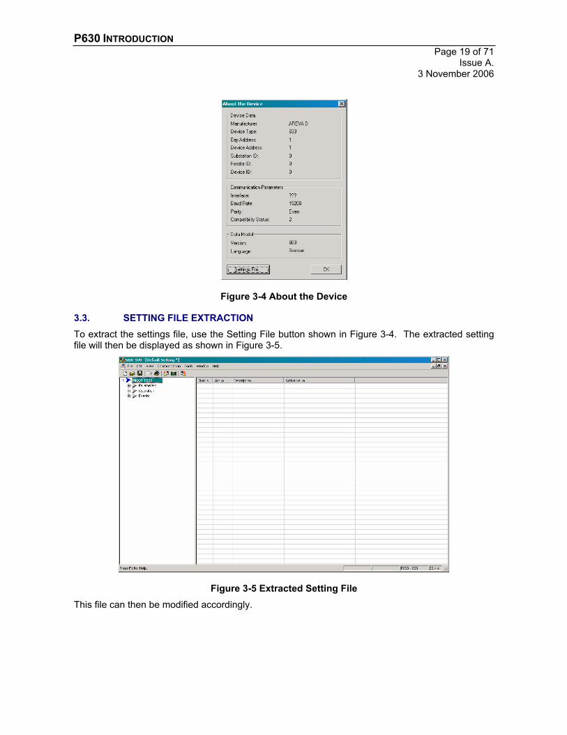
3.3. SETTING FILE EXTRACTION To extract the settings file, use the Setting File button shown in Figure 3-4. The extracted setting file will then be displayed as shown in Figure 3-5.
Figure 3-5 Extracted Setting File This file can then be modified accordingly.

P630 INTRODUCTION Page 20 of 71Issue A. 3 November 2006
3.4. DATA MODEL EXTRACTION If an older version of MiCOM S1 is being used, it is possible that the data model that the relay is using is not present in the S&R-103 software.
Figure 3-6 Data Model Not Found If this is the case, then it is possible to extract the data model from the relay, Communication->Read Data Model. Save the data model in the default folder specified.
Figure 3-7 Data Model Extraction A new settings file can then be created manually, File-New.
Figure 3-8 New Settings File Select Setting File and then select the correct relay model and data model type, according to the relay model, shown by performing an identify device, see Figure 3-4, or from the relay model number on the device. If you choose an incompatible model type then you might be able to convert it at a later time, see section 9.
Figure 3-9 Data Model Selection
P630 INTRODUCTION Page 21 of 71
Issue A. 3 November 2006
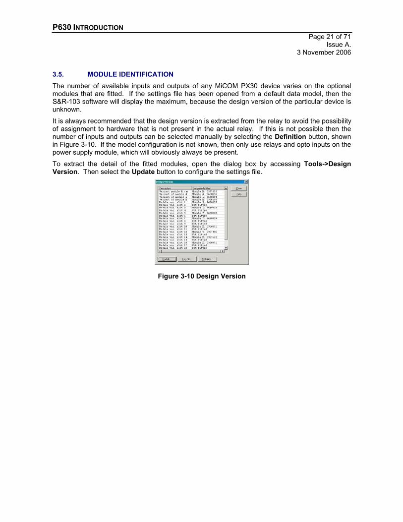
3.5. MODULE IDENTIFICATION The number of available inputs and outputs of any MiCOM PX30 device varies on the optional modules that are fitted. If the settings file has been opened from a default data model, then the S&R-103 software will display the maximum, because the design version of the particular device is unknown.
It is always recommended that the design version is extracted from the relay to avoid the possibility of assignment to hardware that is not present in the actual relay. If this is not possible then the number of inputs and outputs can be selected manually by selecting the Definition button, shown in Figure 3-10. If the model configuration is not known, then only use relays and opto inputs on the power supply module, which will obviously always be present.
To extract the detail of the fitted modules, open the dialog box by accessing Tools->Design Version. Then select the Update button to configure the settings file.
Figure 3-10 Design Version
P630 INTRODUCTION Page 22 of 71Issue A. 3 November 2006
3.6. MODIFYING PARAMETERS This section explains how to modify settings via the communication interface.
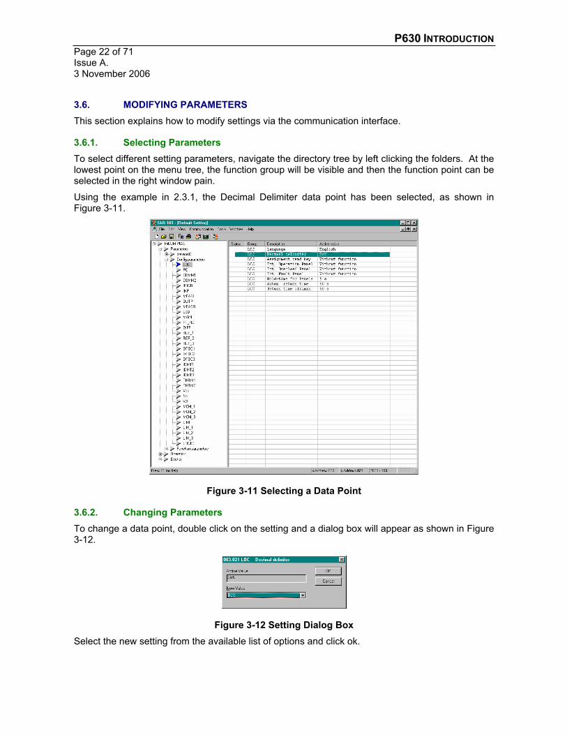
3.6.1. Selecting Parameters To select different setting parameters, navigate the directory tree by left clicking the folders. At the lowest point on the menu tree, the function group will be visible and then the function point can be selected in the right window pain.
Using the example in 2.3.1, the Decimal Delimiter data point has been selected, as shown in Figure 3-11.
Figure 3-11 Selecting a Data Point
3.6.2. Changing Parameters To change a data point, double click on the setting and a dialog box will appear as shown in Figure3-12.
Figure 3-12 Setting Dialog Box Select the new setting from the available list of options and click ok.
P630 INTRODUCTION Page 23 of 71
Issue A. 3 November 2006
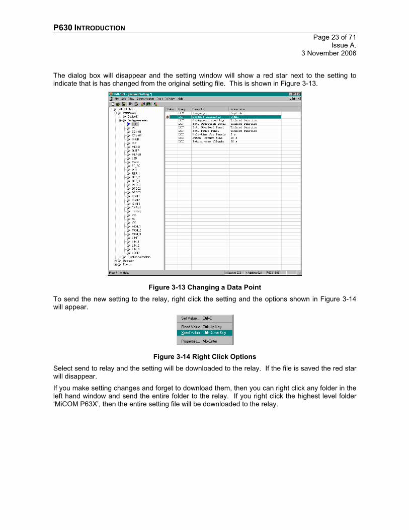
The dialog box will disappear and the setting window will show a red star next to the setting to indicate that is has changed from the original setting file. This is shown in Figure 3-13.
Figure 3-13 Changing a Data Point To send the new setting to the relay, right click the setting and the options shown in Figure 3-14will appear.
Figure 3-14 Right Click Options Select send to relay and the setting will be downloaded to the relay. If the file is saved the red star will disappear.
If you make setting changes and forget to download them, then you can right click any folder in the left hand window and send the entire folder to the relay. If you right click the highest level folder ‘MiCOM P63X’, then the entire setting file will be downloaded to the relay.

P630 INTRODUCTION Page 24 of 71Issue A. 3 November 2006
4. SETTING CONFIGURATION The configuration options of the PX30 range of relays is vast and extremely flexible. However this adds to the complexity of the relay and reduces the simplicity of the user interface. It is therefore highly recommended to attempt setting configuration and changes via the communication port using the S&R-103 software.
In this section a single function will be enabled and configured to drive an output relay, with an opto input configured as a block. These functions cover the primary operations that a user may wish to accomplish.
The function that will be enabled is over current protection (IDMT1).
4.1. STARTING POINT The most suitable starting point is a default starting point, achieved by performing a cold restart, see section 2.3.3, which will place the relay into its default settings, or start with a new default settings file. If the relay is available, update the hardware configuration by performing a Module Identification, see section 3.5.
The relay should be reset, resulting in only the Healthy LED remaining illuminated. If this is not the case, refer back to section 2.3.

P630 INTRODUCTION Page 25 of 71
Issue A. 3 November 2006
4.2. ENABLING PROTECTION The following steps are required to enable a protection function.
4.2.1. Select function from the available list of functions Locate the function group IDMT1, select the With option and send to the relay.
The function group should now be visible in the following two locations:

P630 INTRODUCTION Page 26 of 71Issue A. 3 November 2006
4.2.2. Enable function from the selected functions Activate the function in each of the following two locations.
Locate General enable USER, select Yes and send to the relay. Leave the selected input at Enda (the HV side).
Locate Enable PS1, select Yes and send to the relay. This is where the individual setting group protection settings can be configured. The function default is No in the remaining subsets 2-4.
Locate the setting Min. trip t. P. This is the minimum trip time; change the setting to zero forinstantaneous operation.

P630 INTRODUCTION Page 27 of 71
Issue A. 3 November 2006
4.2.3. Enable master protection enable. Check the ‘Out of Service’ LED status. If making setting changes via the front port then this setting must be disabled ‘off’. However, we are making changes via the communications so the setting can be enabled ‘on’. If the ‘out of service’ LED is illuminated then enable the protection by following section 2.3.6, also described below.
Locate Protection enabled, select Yes and send to the relay. If the ‘Out of Service’ LED was enabled, it should be extinguished.
The protection function is now enabled; however the protection function outputs need to be configured.

P630 INTRODUCTION Page 28 of 71Issue A. 3 November 2006
4.3. CONFIGURING OUTPUT RELAYS There are different ways to configure output relays.
i. Directly map a protection/control function output to an output relay. The disadvantage is that only one input can drive the output relay.
ii. Map a protection/control function output into a ‘Tripping’ command and then map this to an output relay. This is normally perfectly adequate for most applications and will be described within this section.
iii. Use the ‘LOGIC’ feature. This is more flexible for complex implementations; this function will be described in section 5. LOGIC should not be used for mapping trip outputs, see section 5 for further information.
P630 INTRODUCTION Page 29 of 71
Issue A. 3 November 2006
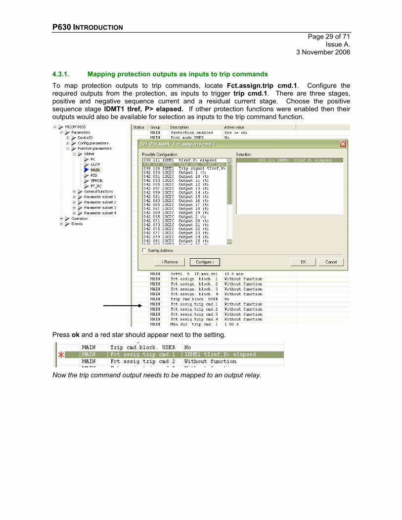
4.3.1. Mapping protection outputs as inputs to trip commands To map protection outputs to trip commands, locate Fct.assign.trip cmd.1. Configure the required outputs from the protection, as inputs to trigger trip cmd.1. There are three stages, positive and negative sequence current and a residual current stage. Choose the positive sequence stage IDMT1 tIref, P> elapsed. If other protection functions were enabled then their outputs would also be available for selection as inputs to the trip command function.
Press ok and a red star should appear next to the setting.
Now the trip command output needs to be mapped to an output relay.
P630 INTRODUCTION Page 30 of 71Issue A. 3 November 2006
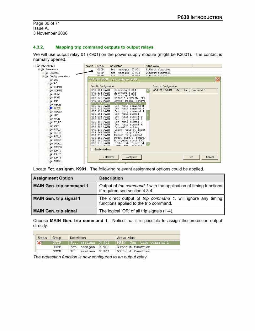
4.3.2. Mapping trip command outputs to output relays We will use output relay 01 (K901) on the power supply module (might be K2001). The contact is normally opened.
Locate Fct. assignm. K901. The following relevant assignment options could be applied.
Assignment Option Description
MAIN Gen. trip command 1 Output of trip command 1 with the application of timing functions if required see section 4.3.4.
MAIN Gen. trip signal 1 The direct output of trip command 1, will ignore any timing functions applied to the trip command.
MAIN Gen. trip signal The logical ‘OR’ of all trip signals (1-4).
Choose MAIN Gen. trip command 1. Notice that it is possible to assign the protection output directly.
The protection function is now configured to an output relay.

P630 INTRODUCTION Page 31 of 71
Issue A. 3 November 2006
4.3.3. *** Test Point 1 *** The function can now be tested.
Slowly increase the three phase current (up to 1A) on the HV side, until the output relay is heard to operate and the trip indication LED is illuminated. Slowly decrease the current until the output relay is heard to reset. Press the CLEAR key twice on the front panel to reset the trip LED.
4.3.4. Minimum duration, latching and resetting of trip commands The trip commands can be latched or assigned a minimum duration (shown below). We will assign a minimum duration. (Note that this could also be achieved through the protection settings, section 4.2.2.
To assign a minimum duration locate Min. dur. trip cmd. 1. Select 1s and send to relay.

P630 INTRODUCTION Page 32 of 71Issue A. 3 November 2006
4.3.5. *** Test Point 2 *** Apply an over current condition and now the relay can be heard to remain operated for 1 second for any fault condition applied for to 1 second.
4.3.6. Mapping the WATCHDOG contact It is always good practice to map a watchdog contact to enable the relay to indicate its ‘healthy’ condition to a monitoring (SCADA) system.
Locate the following relay K908 (might be K2008), which is the relay nearest the power supply inputs. Assign this contact to MAIN Blocked/faulty.
The watchdog contact is conventionally a normally closed contact, which is energised closed by the relay, hence if the relay powers off or there is an auxiliary supply problem then the contact will naturally open communicating a problem. Therefore modify the corresponding relay contact setting.

P630 INTRODUCTION Page 33 of 71
Issue A. 3 November 2006
The relay can also monitor its output contacts to verify that operation has taken place, when the relay logic commands an operation.
Locate MAIN Fct. assign. fault. Assign this contact to the trip relay output and any other relay outputs as necessary. There are also settings for the current circuit supervision and failures of complete hardware modules.

P630 INTRODUCTION Page 34 of 71Issue A. 3 November 2006
4.4. CONFIGURING OPTO-INPUTS There are different ways of configuring opto inputs.
i. Directly map an opto input to a protection/control function. The disadvantage is that only one relay input can drive the protection function.
ii. Map an opto input through the ‘Blocking’ command. This is normally perfectly adequate for most applications and will be described within this section.
iv. Use the ‘LOGIC’ feature. This is more flexible for complex implementations; this function will be described in section 5.

P630 INTRODUCTION Page 35 of 71
Issue A. 3 November 2006
4.4.1. Mapping opto inputs as inputs to blocking commands We will use opto input U901 (might be U2001) on the power supply board, however any available input would be acceptable.
Locate Fct.assign.U901. Select MAIN Blocking 1 EXT and send to the relay.
This has mapped the opto input as an input into this blocking command. Any other opto inputs can also be mapped to this command. Notice that it is possible to assign the opto input to protection/control inputs directly, such as IDMT1 Block Iref, P> EXT, which can be used to block the IDMT1 positive sequence over current protection.
Next we have to decide if this input is active ‘high’ or active ‘low’, these settings are in the same location.
Locate Oper. Mode U901. The default should be ‘high’.
Now the blocking command output needs to be mapped to a function input.
P630 INTRODUCTION Page 36 of 71Issue A. 3 November 2006
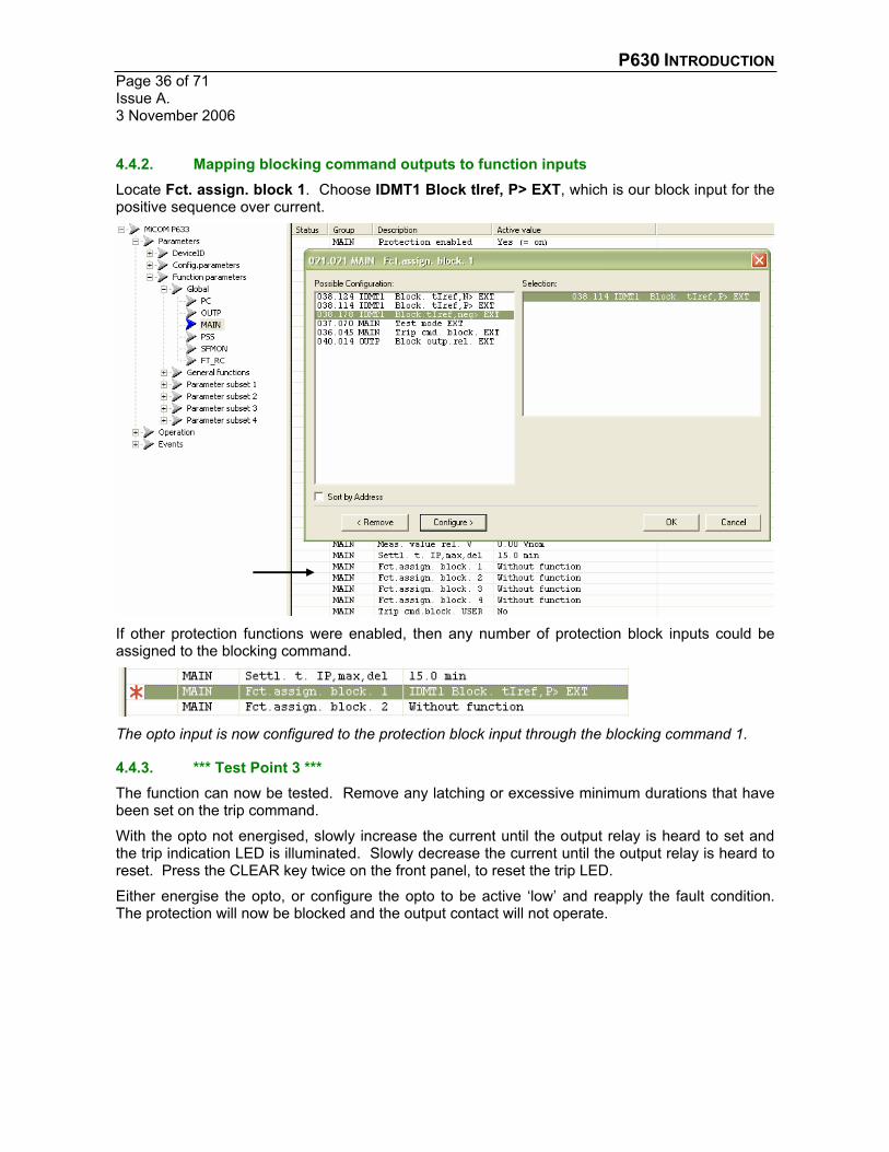
4.4.2. Mapping blocking command outputs to function inputs Locate Fct. assign. block 1. Choose IDMT1 Block tIref, P> EXT, which is our block input for the positive sequence over current.
If other protection functions were enabled, then any number of protection block inputs could be assigned to the blocking command.
The opto input is now configured to the protection block input through the blocking command 1.
4.4.3. *** Test Point 3 *** The function can now be tested. Remove any latching or excessive minimum durations that have been set on the trip command.
With the opto not energised, slowly increase the current until the output relay is heard to set and the trip indication LED is illuminated. Slowly decrease the current until the output relay is heard to reset. Press the CLEAR key twice on the front panel, to reset the trip LED.
Either energise the opto, or configure the opto to be active ‘low’ and reapply the fault condition. The protection will now be blocked and the output contact will not operate.
P630 INTRODUCTION Page 37 of 71
Issue A. 3 November 2006
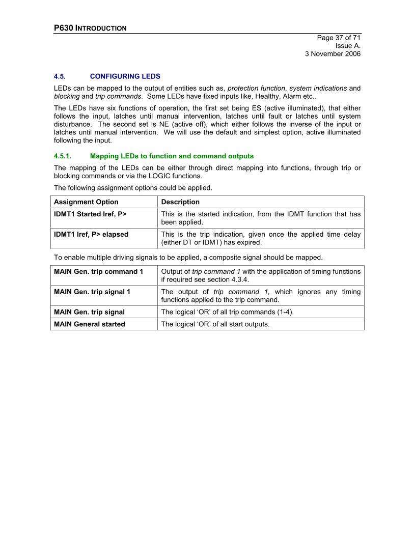
4.5. CONFIGURING LEDS LEDs can be mapped to the output of entities such as, protection function, system indications and blocking and trip commands. Some LEDs have fixed inputs like, Healthy, Alarm etc..
The LEDs have six functions of operation, the first set being ES (active illuminated), that either follows the input, latches until manual intervention, latches until fault or latches until system disturbance. The second set is NE (active off), which either follows the inverse of the input or latches until manual intervention. We will use the default and simplest option, active illuminated following the input.
4.5.1. Mapping LEDs to function and command outputs The mapping of the LEDs can be either through direct mapping into functions, through trip or blocking commands or via the LOGIC functions.
The following assignment options could be applied.
Assignment Option Description
IDMT1 Started Iref, P> This is the started indication, from the IDMT function that has been applied.
IDMT1 Iref, P> elapsed This is the trip indication, given once the applied time delay (either DT or IDMT) has expired.
To enable multiple driving signals to be applied, a composite signal should be mapped.
MAIN Gen. trip command 1 Output of trip command 1 with the application of timing functions if required see section 4.3.4.
MAIN Gen. trip signal 1 The output of trip command 1, which ignores any timing functions applied to the trip command.
MAIN Gen. trip signal The logical ‘OR’ of all trip commands (1-4).
MAIN General started The logical ‘OR’ of all start outputs.

P630 INTRODUCTION Page 38 of 71Issue A. 3 November 2006
Select the LED Fct. Assignm. H*, (where * is 5-16) and select the input desired and send to relay. H4 can be configured, but by default it is set to illuminate on a protection trip.
4.5.2. *** Test Point 4 *** Remove the opto input block signal and apply the fault condition. The LEDs should illuminate as configured.
Try changing the LED operating modes and observe the behaviour.

P630 INTRODUCTION Page 39 of 71
Issue A. 3 November 2006
5. SCHEME LOGIC The scheme logic is a powerful feature that enables users to link binary signals within a framework of Boolean equations.
It is important to remember that although the scheme logic is flexible, it can slow down signals due the additional computation required. This means that trip signals (if at all possible) should not be assigned through LOGIC. Output relays should be driven by trip commands and the protection trip signals should be gated with LOGIC output, within the trip commands.
Only a basic use of LOGIC is shown here, refer to the manual for further applications.
5.1. PSL EDITOR The programmable scheme logic is similar to the Px40 series equivalent, except that the flow of information can flow from ‘left to right’ or ‘right to left’ through the symbols. Therefore understanding if a symbol generates or accepts a signal is required.
The constraints on signals are also not clear – you cannot AND two inputs directly into an output contact. This is not allowed in settings and therefore not allowed in the PSL, although there is not an immediate indication of this. Therefore the PSL editor is a tool that is best used to view and verify settings, rather than create the settings directly.
The PSL editor can be used without the LOGIC function enabled.
5.2. CONFIGURING LOGIC To make use of the LOGIC function it first has to be enabled.
Locate the function group LOGIC, select the With option and send to the relay.

P630 INTRODUCTION Page 40 of 71Issue A. 3 November 2006
5.2.1. LOGIC Configuration The logic function consists primarily of the input & outputs shown below.
A Any number of input signals can be configured as inputs with the boolean functions ‘AND’, ‘OR’ and ‘NOT’.
B The logic outputs are available for use in the Trip or Blocking Command functions or any other LOGIC functions and they can be mapped to relay outputs. The timing functions can be used to affect the pick-up, drop-off or duration of the output signal LOGIC Output (t) incomparison to the signal LOGIC Output.
C The outputs can also be assigned directly to any internal functions such as blocking or control signal inputs.
5.2.2. Map an Opto-Input to a LOGIC input signal For this example, an opto-input is required to accept an intertrip signal, map this through the LOGIC function and OR it with the IDMT1 trip already established to operate the output contact. However this intertrip signal will also be used to block the IDMT1 protection function.
Set U902 (or U2002) to LOGIC Input 1 EXT.
The opto-input is now configured to a LOGIC input signal.

P630 INTRODUCTION Page 41 of 71
Issue A. 3 November 2006
5.2.3. Map the LOGIC input signal into a LOGIC function Locate Fct. assignm. outp. 1 and set it to LOGIC Input 1 EXT.
The LOGIC input signal 1 is now mapped into the LOGIC function 1.
No locate Op. mode t output 1 and set it to Minimum time, which makes the LOGIC output signals identical; this is required because within the trip commands, only the (t) signals are available for mapping.

P630 INTRODUCTION Page 42 of 71Issue A. 3 November 2006
5.2.4. Mapping LOGIC function outputs to protection function inputs Locate Sig. assig. outp. 1 and set it to IDMT1 Block. tIref, P> EXT.
The LOGIC function 1 signal output is now mapped to the IDMT1 protection blocking signal.
5.2.5. Mapping a LOGIC function output into a Trip Command Locate Fct. assig. trip cmd. 1 and add the setting LOGIC Ouput 1 (t).
When either the opto input or IDMT function operate then a trip output will occur.
P630 INTRODUCTION Page 43 of 71
Issue A. 3 November 2006
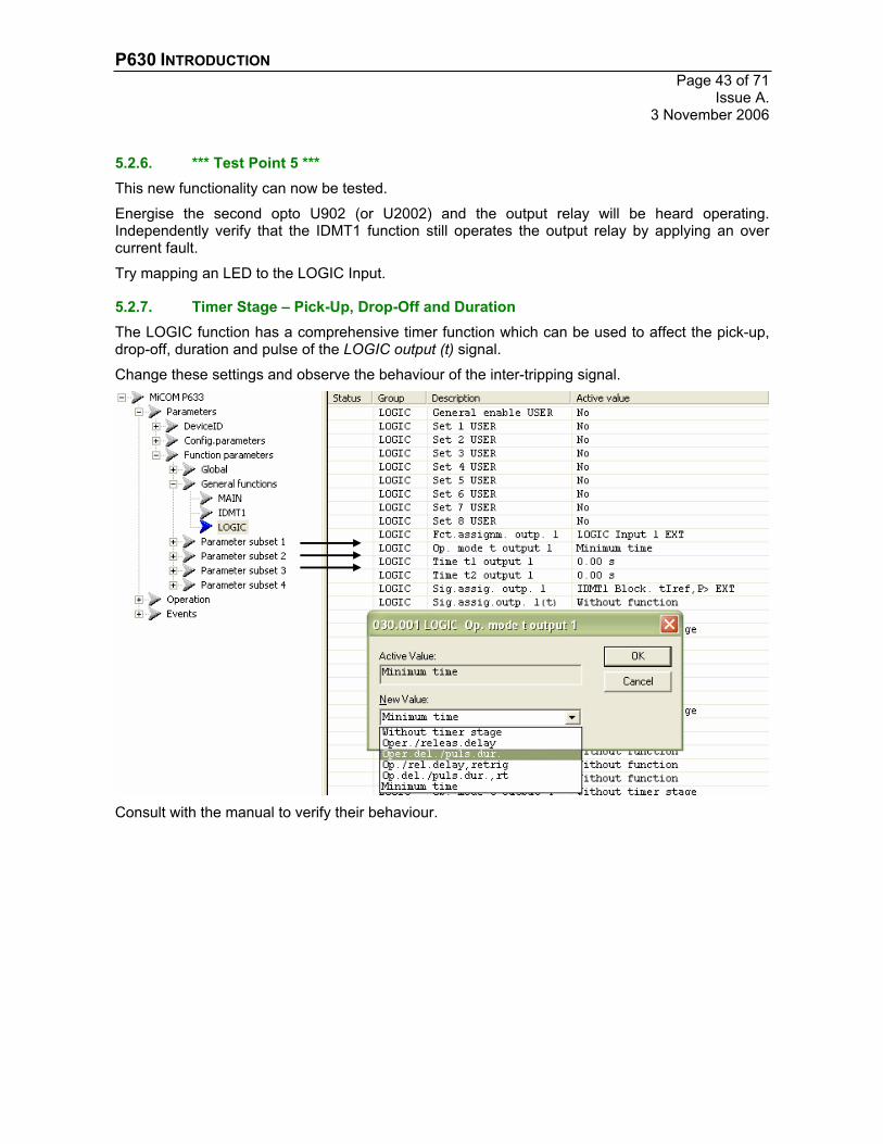
5.2.6. *** Test Point 5 *** This new functionality can now be tested.
Energise the second opto U902 (or U2002) and the output relay will be heard operating. Independently verify that the IDMT1 function still operates the output relay by applying an over current fault.
Try mapping an LED to the LOGIC Input.
5.2.7. Timer Stage – Pick-Up, Drop-Off and Duration The LOGIC function has a comprehensive timer function which can be used to affect the pick-up, drop-off, duration and pulse of the LOGIC output (t) signal.
Change these settings and observe the behaviour of the inter-tripping signal.
Consult with the manual to verify their behaviour.
P630 INTRODUCTION Page 44 of 71Issue A. 3 November 2006
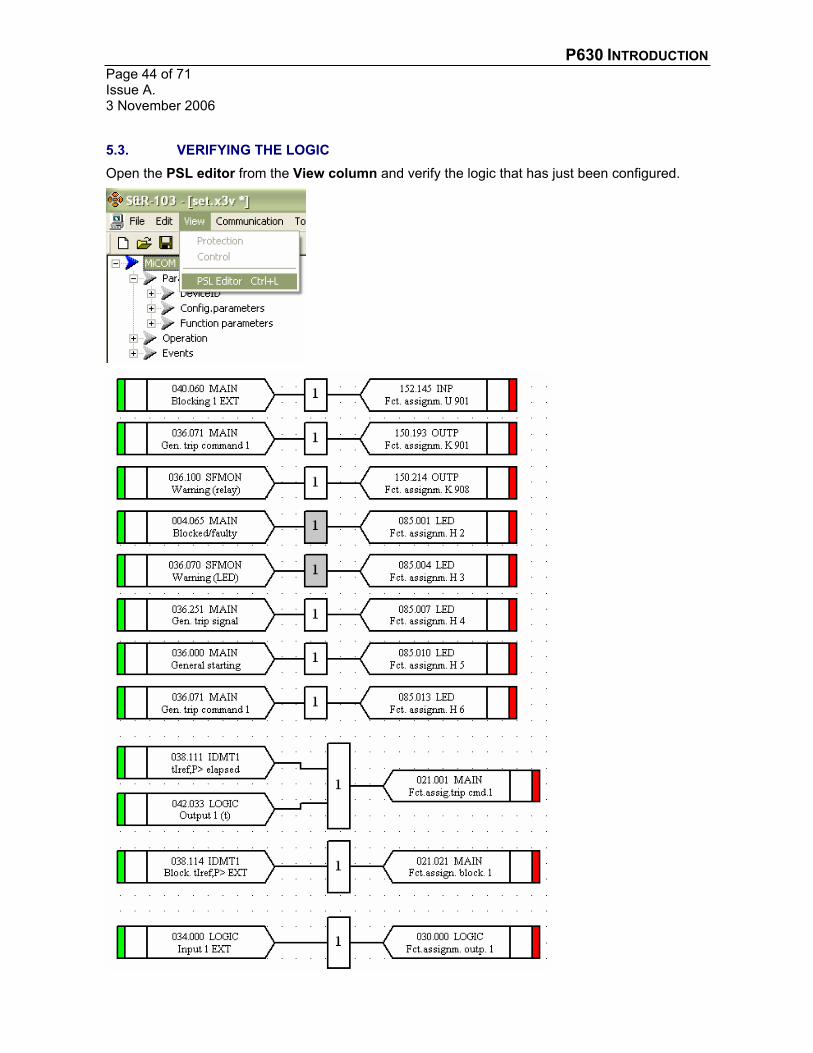
5.3. VERIFYING THE LOGIC Open the PSL editor from the View column and verify the logic that has just been configured.
P630 INTRODUCTION Page 45 of 71
Issue A. 3 November 2006
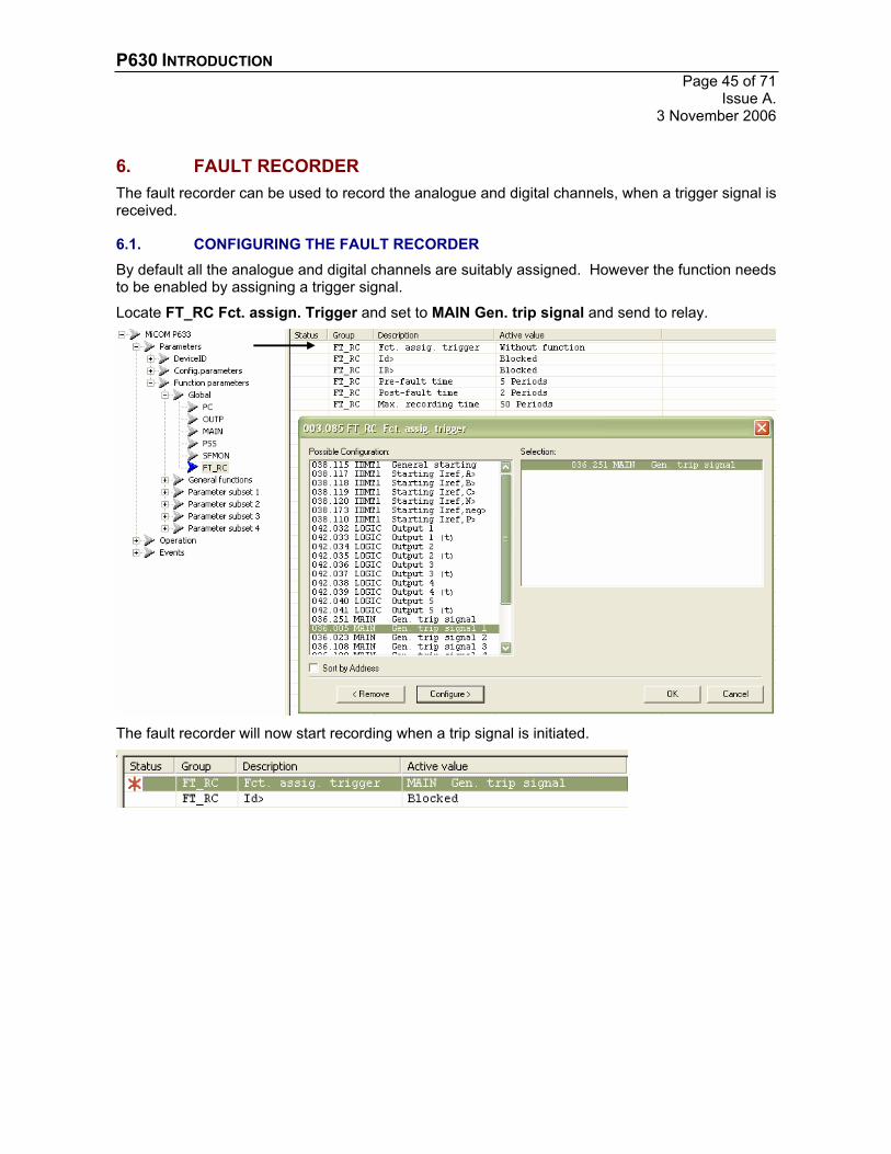
6. FAULT RECORDER The fault recorder can be used to record the analogue and digital channels, when a trigger signal is received.
6.1. CONFIGURING THE FAULT RECORDER By default all the analogue and digital channels are suitably assigned. However the function needs to be enabled by assigning a trigger signal.
Locate FT_RC Fct. assign. Trigger and set to MAIN Gen. trip signal and send to relay.
The fault recorder will now start recording when a trip signal is initiated.

P630 INTRODUCTION Page 46 of 71Issue A. 3 November 2006
6.1.1. Configuring the read key To access fault records more quickly via the relay front panel, the read key can be assigned as a quick access key.
Locate LOC Assignment read key and select FT_RC Fault recording 1.
Fault records can be accessed by pressing the read key at the relay default display.

P630 INTRODUCTION Page 47 of 71
Issue A. 3 November 2006
6.2. EXTRACTION OF FAULT DATA To extract a fault record, select Readout of Fault in the Communication column.
Select the fault record.
Follow the instructions and save the file in comtrade format for viewing.

P630 INTRODUCTION Page 48 of 71Issue A. 3 November 2006
6.3. CLEARING FAULT RECORDS
6.3.1. Clearing Fault Records from the Display The simplest method for clearing fault records from the display, is to access them using the readkey as detailed in section 6.1.1, then return to the default display by repeatedly pressing the uparrow key.
The fault panel should then disappear and the operation panel should then be observable.
If the operation panel is not visible, press the ‘clear’ and ‘up arrow’ key simultaneously to toggle between the default display and the operation panel.
6.3.2. Clearing Fault Records from the Relay Memory To clear the fault records, the following location needs to be accessed via the front panel or through the communications S&R-103.
Change the setting to execute and send to the relay. Remember to change the setting back to don’t execute. (This is not necessary via the front panel)
P630 INTRODUCTION Page 49 of 71
Issue A. 3 November 2006
7. OPERATION, OVERLOAD AND FAULT PANEL
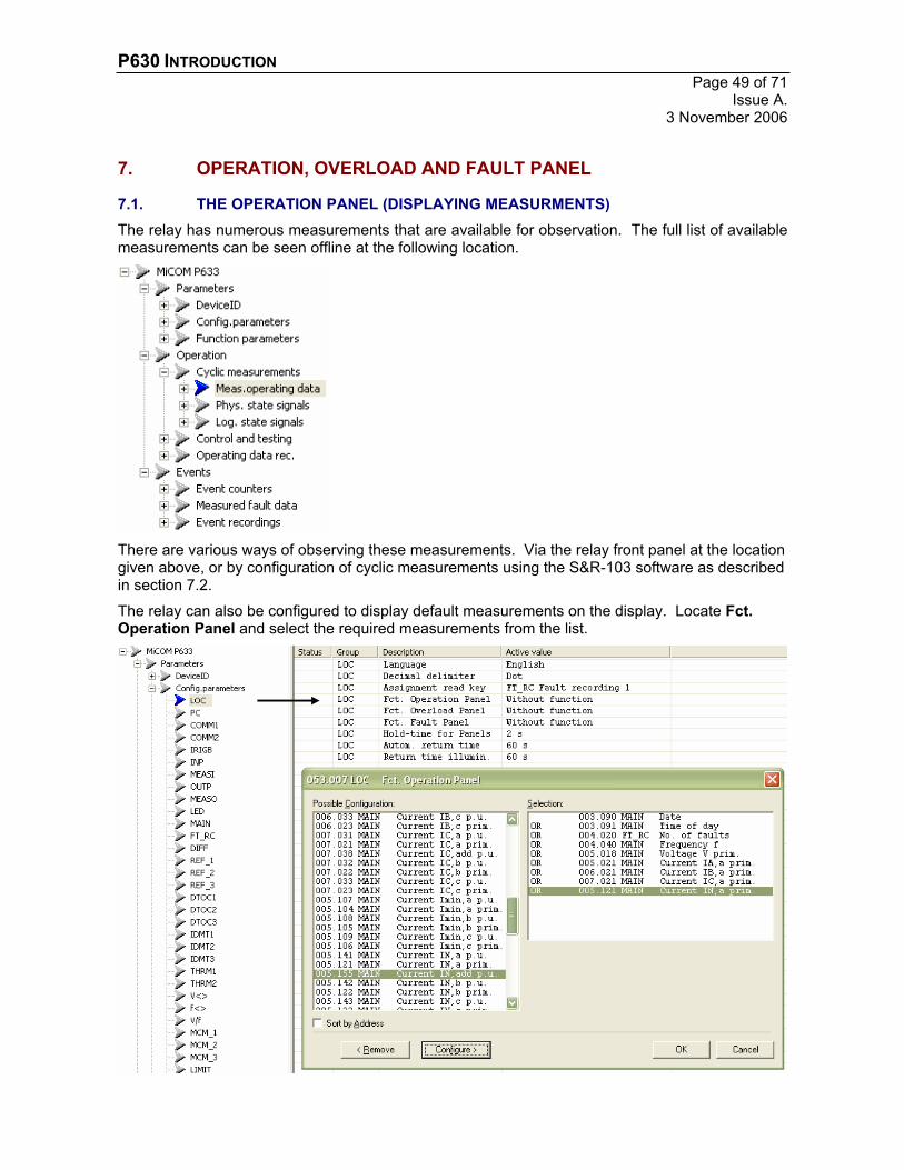
7.1. THE OPERATION PANEL (DISPLAYING MEASURMENTS) The relay has numerous measurements that are available for observation. The full list of available measurements can be seen offline at the following location.
There are various ways of observing these measurements. Via the relay front panel at the location given above, or by configuration of cyclic measurements using the S&R-103 software as described in section 7.2.
The relay can also be configured to display default measurements on the display. Locate Fct.Operation Panel and select the required measurements from the list.
P630 INTRODUCTION Page 50 of 71Issue A. 3 November 2006
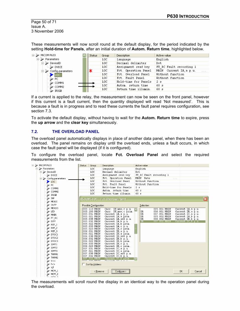
These measurements will now scroll round at the default display, for the period indicated by the setting Hold-time for Panels, after an initial duration of Autom. Return time, highlighted below.
If a current is applied to the relay, the measurement can now be seen on the front panel, however if this current is a fault current, then the quantity displayed will read ‘Not measured’. This is because a fault is in progress and to read these currents the fault panel requires configuration, see section 7.3.
To activate the default display, without having to wait for the Autom. Return time to expire, press the up arrow and the clear key simultaneously.
7.2. THE OVERLOAD PANEL The overload panel automatically displays in place of another data panel, when there has been an overload. The panel remains on display until the overload ends, unless a fault occurs, in which case the fault panel will be displayed (if it is configured).
To configure the overload panel, locate Fct. Overload Panel and select the required measurements from the list.
The measurements will scroll round the display in an identical way to the operation panel during the overload.
P630 INTRODUCTION Page 51 of 71
Issue A. 3 November 2006
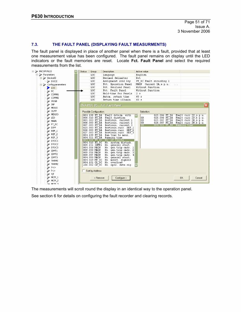
7.3. THE FAULT PANEL (DISPLAYING FAULT MEASURMENTS) The fault panel is displayed in place of another panel when there is a fault, provided that at least one measurement value has been configured. The fault panel remains on display until the LED indicators or the fault memories are reset. Locate Fct. Fault Panel and select the required measurements from the list.
The measurements will scroll round the display in an identical way to the operation panel.
See section 6 for details on configuring the fault recorder and clearing records.

P630 INTRODUCTION Page 52 of 71Issue A. 3 November 2006
8. CONFIGURATION OF CYCLIC MEASUREMENTS Cyclic measurements is a feature within the S&R-103 software that enables a relay to be polled for measurements. This is a very useful tool that allows measurements to be read form the relay, without having to interrogate the relay directly.
To configure cyclic measurements, select Cyclic Readout of Data form the Communicationcolumn.
An option box will appear; select configure and select the measurements from the list that are required.
Select OK and then select Start and the measurements will appear.

P630 INTRODUCTION Page 53 of 71
Issue A. 3 November 2006
The list can be saved to avoid reconfiguration each time the feature is utilised.

P630 INTRODUCTION Page 54 of 71Issue A. 3 November 2006
9. FILE COMPARISON AND CONVERSION The following functions can be performed on a settings file, using the S&R103 software.
9.1. FILE COMPARISON This function will accept two settings files and display the differences. This function is very useful for quickly determining the differences in settings, between two seemingly identical files.
Select Tools and Compare Settings File from the menu.
Then select the reference file with respect to one that is already open.
The number of deviations will then be displayed, if any. The file can then be opened and the deviations read.
In this example it can be seen that the CT ratios are different between the two files.

P630 INTRODUCTION Page 55 of 71
Issue A. 3 November 2006
9.2. FILE CONVERSION If the full model number is not known, then it might not be possible to select the correct setting file. If for example, the only information available is P633, then it is not known what data model version is required, but fortunately the setting files can be converted between data models. If the data model is not known, select the latest possible German derivative and select the regional language to be English.
For example P633 – 605 German
Select Tools and Program Settings form the menu.
Check that the language of the data model is set to Reference Language English

P630 INTRODUCTION Page 56 of 71Issue A. 3 November 2006
The settings file can then be configured. If however when the file is downloaded to the relay, a message is displayed informing that the data model is incorrect, perform a relay identification as detailed in section 3.2. This will result in the following information with the data model version displayed.
The setting file is 605 but the relay is 603. Close the dialog box so that only the settings file is open and select Tools and Convert Settings File from the menu

P630 INTRODUCTION Page 57 of 71
Issue A. 3 November 2006
Select a name and location for the newly converted file. And then select the data model version that the file is to be converted to, in this case P633 – 603 German.
A file compare is then performed automatically (see section 9.1) and the option to observe the deviations is given. The new file can then be opened and downloaded successfully to the relay.

P630 INTRODUCTION Page 58 of 71Issue A. 3 November 2006
10. CONFIGURATION AND TEST OF A DIFFERENTIAL PROTECTION SCHEME
The primary protection function on a P63x is the differential protection. This protection function will now be configured and tested from a default file.
A P633 (3 winding transformer relay) has been used in this example. The b & c ends have been combined to enable a simple two winding example, therefore only two winding are described.
10.1. SETTING THE ‘DIFF’ PROTECTION SCHEME
Parameter Setting
Frequency 50Hz
VT Primary Voltage 3.3kV
HV CT Primary Current 400A
HV Neutral CT Primary Current 400A
LV CT Primary Current 3000A
LV Neutral CT Primary Current 3000A
VT Secondary Voltage 110V
HV CT Secondary Current 1A
HV Neutral CT Secondary Current 1A
LV CT Secondary Current 1A
LV Neutral CT Secondary Current 1A
Transformer HV Voltage 3.3kV
Transformer LV Voltage 0.42kV
Transformer Rating 2MVA
Transformer Group Dny11
First stage current setting 0.1
Second stage current setting 11
Third stage current setting 11
10.1.1. Enable the DIFF function Enable protection functions
Parameters Function parameters Global Main Protection enabled… Change to yes (= on)
Make the DIFF function available Parameters Config.parameters DIFF Function Group DIFF… Change to With
Enable the DIFF function Parameters Function parameters Global functions DIFF General enable USER… Change to yes
Enable the DIFF function in setting group 1 Parameters Function parameters Parameter subset 1 DIFF Enable PS1… Change to yes

P630 INTRODUCTION Page 59 of 71
Issue A. 3 November 2006
10.1.2. System & Transformer Parameters Enter the system frequency
Parameters Function parameters Global Main Nominal frequ. fnom… Set to 50HzEnter the transformer voltages (not CT ratios)
Parameters Function parameters General functions MAIN
Vnom. prim., end a… Set to 3.3kV
Vnom. prim., end b… Set to 0.4kV
Evaluation IN, end a… Set to Calculated
Evaluation IN, end b… Set to Calculated
Enter the transformer parameters Parameters Function parameters Global DIFF
Reference power Sref… Set to 2MVA
Vector grp. Ends a-b… Set to 11
10.1.3. CT and VT Ratios Enter the CT and VT ratios
Parameters Function parameters Global Main
Inom C.T.prim., end a… Set to 400A
Inom C.T.prim., end b… Set to 3000A
Inom C.T.Yprim., end a… Not required, therefore leave at default
Inom C.T.Yprim., end b… Set to 3000A
Vnom V.T. prim… Set to 3.3kV
Inom device, end a… Set to 1A
Inom device, end b… Set to 1A
IY nom device, end a… Not required, therefore leave at default
IY nom device, end b… Set to 1A
Vnom V.T. sec… Set to 110V
10.1.4. Differential Settings Enter the differential settings
Parameters Function parameters Parameter subset 1 DIFF
Idiff> PS1… Set to 0.1 Iref
Idiff>> PS1… Set to 11 Iref
Idiff>>> PS1… Set to 11 Iref
Enter the bias settings m1 PS1… Set to 0.3
m2 PS1… Set to 0.7

P630 INTRODUCTION Page 60 of 71Issue A. 3 November 2006
10.1.5. Configure the Trip Commands Assign differential operate signal to trip command 1
Parameters Function parameters Global Main Fct.assig.trip cmd.1… Set to DIFF trip signal
10.1.6. Configure an Output Trip Relay, LEDs & Watchdog Contact Configure output relay
Parameters Config.parameters OUTP Fct assignm. K****l… Set to MAIN Gen. trip signal
Configure the watchdog contact Parameters Config.parameters OUTP Fct assignm. K****… Set to MAIN Blocked/faulty
Parameters Config.parameters OUTP Oper. mode K****… Set to NE updating
Parameters Function parameters Global Main Fct. assign. Fault… Configure the output contact
Configure LED (of limited use in this example due to instantaneous protection function) Parameters Config.parameters LED Fct. assignm. H16… Set to DIFF starting
10.1.7. Configure the Fault Recorder and the Operation & Fault Pages Configure fault recorder by specifying a trigger
Parameters Function parameters Global FT_RC Fct �ssign. trigger… Set to MAIN Gen. trip signal
Assign the ‘read’ key as a shortcut to the fault record Parameters Config.parameters LOC Assignment read key… Set to FT_RC Fault recording 1
Assign some useful parameters to the operation panel Parameters Config.parameters LOC Fct. Operation Panel Configure the following for example.
DIFF Diff. current 1
DIFF Restrain. Current 1
Current IA, a p.u.
Current IA, b p.u.
Assign some useful parameters to the operation panel Parameters Config.parameters LOC Fct. Fault Panel Configure the following for example.
FT_DA Diff. current 1
FT_DA Restrain. Current 1
FT_DA Fault curr. IP, a p.u.
FT_DA Fault curr. IP, b p.u.

P630 INTRODUCTION Page 61 of 71
Issue A. 3 November 2006
10.2. TESTING THE DIFFERENTIAL BIAS CHARACTERISTIC Before testing can commence the relative current and CT matching factors need to be determined.
10.2.1. Reference Currents and CT Matching Factors The reference currents for each winding need to be calculated.
9.3493.33
23 ,
, kVMVA
V
SI
anom
refaref
75.28864.03
23 ,
, kVMVA
V
SI
bnom
refbref
The CT matching factors are therefore.
143.19.349
400,,
,
aref
anom
II
aKam
039.175.2886
3000,,
,
aref
anom
II
bKam
However these can be extracted from the relay. Select read at the following location. Parameters Function parameters General functions DIFF
The values will then be read from the relay.
The relay will verify that these reference currents and matching factors are within sensible ranges. If not then a warning will be displayed.

P630 INTRODUCTION Page 62 of 71Issue A. 3 November 2006
The values given above are also available using an Excel worksheet. A screen shot of the above settings is shown below.

P630 INTRODUCTION Page 63 of 71
Issue A. 3 November 2006
10.2.2. Spot Testing the Relay Settings To spot test using the actual relay settings, then a suitable tool should be used to aid computation of the test parameters and verification of the measurements.
The simplest stability check is to apply the opposing CT matching factors as the energising quantities. The appropriate quantities and angles are shown below.
Stability check: verify that trip operation does not occur.
P630 INTRODUCTION Page 64 of 71Issue A. 3 November 2006
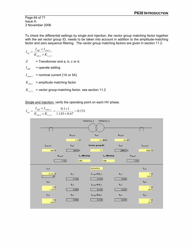
To check the differential settings by single end injection, the vector group matching factor together with the set vector group ID, needs to be taken into account in addition to the amplitude-matching factor and zero sequence filtering. The vector group matching factors are given in section 11.2.
zysxam
xnomdiffinj KK
III
,,,
,
Z = Transformer end a, b, c or d.
diffI = operate setting
xnomI , = nominal current (1A or 5A)
zamK , = amplitude matching factor
zysK ,, = vector group-matching factor, see section 11.2
Single end injection: verify the operating point on each HV phase.
131.067.0143.111.0
,,,
,
zysaam
anomdiffinj KK
III

P630 INTRODUCTION Page 65 of 71
Issue A. 3 November 2006
Single end injection: verify the operating point on each LV phase.
166.058.0039.111.0
,,,
,
zysbam
bnomdiffinj KK
III

P630 INTRODUCTION Page 66 of 71Issue A. 3 November 2006
10.2.3. Testing the Differential Characteristic using Harmonised Relay Settings To simplify testing the following setting modifications can be undertaken.
The first simplification is to change the transformer type from a Dyn11 to Yy0, which means that there is no phase shift between the HV and LV sides.
Parameters Function parameters Global DIFF Vector grp. Ends a-b… Set to 0 (also a-c if req’d)
The second simplification is to remove zero sequence filtering, see section 11.1 for an explanation of this feature.
Parameters Function parameters Parameter subset 1 DIFF
0-seq. Filt. A en. PS1… Set to No
0-seq. filt. b en. PS1… Set to No
The CT ratios can be modified, so that the CT matching factors are near identical. This is achieved by using the reference currents as the CT ratios. This is shown below.
Enter the new CT ratios Parameters Function parameters Global Main
Inom C.T.prim., end a… Set to 350A
Inom C.T.prim., end b… Set to 2887A
The CT matching factors are now (very conveniently) both 1A. Which means the differential characteristic can be verified more simply. If a P633 (3 winding) relay is being used, apply the full current to the HV side (side a) and split the current equally between the LV sides (side b & c).

P630 INTRODUCTION Page 67 of 71
Issue A. 3 November 2006
The characteristic can now be tested, using a single phase IA.
a) Slowly increase the current IAa from 0 in 0.01A steps until the relay operates, whilst leaving IAb at 0 Amps. Record the operating current IAa in the table provided.
We have now assessed the minimum sensitivity of the relay. This gives an indication of the current required to cause operation for a genuine internal fault. Notice that the relay does operate at exactly the Idiff> setting of 0.1.
The next phase of testing a bias differential relay, is to establish that the bias characteristic matches the relay settings. This is done by adjusting the magnitude of the two anti-phase currents (IAa and IAb) until the relay operates. At the point of operation, the differential and bias currents can be calculated and plotted, to see if they correlate with the relay settings
b) Apply the initial currents stated in the table and then slowly increase current IAa until the relay operates. Enter the current at which the relay operates in the ‘IAa Trip’ column, in the table below.
Calculate the bias/restrain and differential currents and then plot them on the graph provided.
Read them from the relay (section 10.2.1)
Read them from the Excel spreadsheet
Or observe the per phase bias/restrain and differential current via the front panel, if they were configured accordingly in section 10.1.7. Press ‘clear’ and ‘up arrow’ key together to toggle the view.
Initial IAa IAb IAa trip Bias/Restrain Current = (IAa trip + IAb)/2
Differential Current = IAa trip – IAb
0.0 0° 0.0 -180° 000 ...111000 000...000555 000 ...111000
0.3 0° 0.3 -180° 000 ...555000 000...444000 000 ...888000
0.6 0° 0.6 -180° 000 ...999111 000...777888 000 ...333111
0.9 0° 0.9 -180° 111 ...333222 111...111111 000 ...444222
1.5 0° 1.5 -180° 222 ...111333 111...888222 000 ...666333
3.5 0° 3.0 -180° 444 ...111555 333...555888 111 ...111555
4.0 0° 3.5 -180° 444 ...999777 444...222444 111 ...444777
8.5 0° 5.5 -180° 999 ...111000 777...333000 333 ...666000
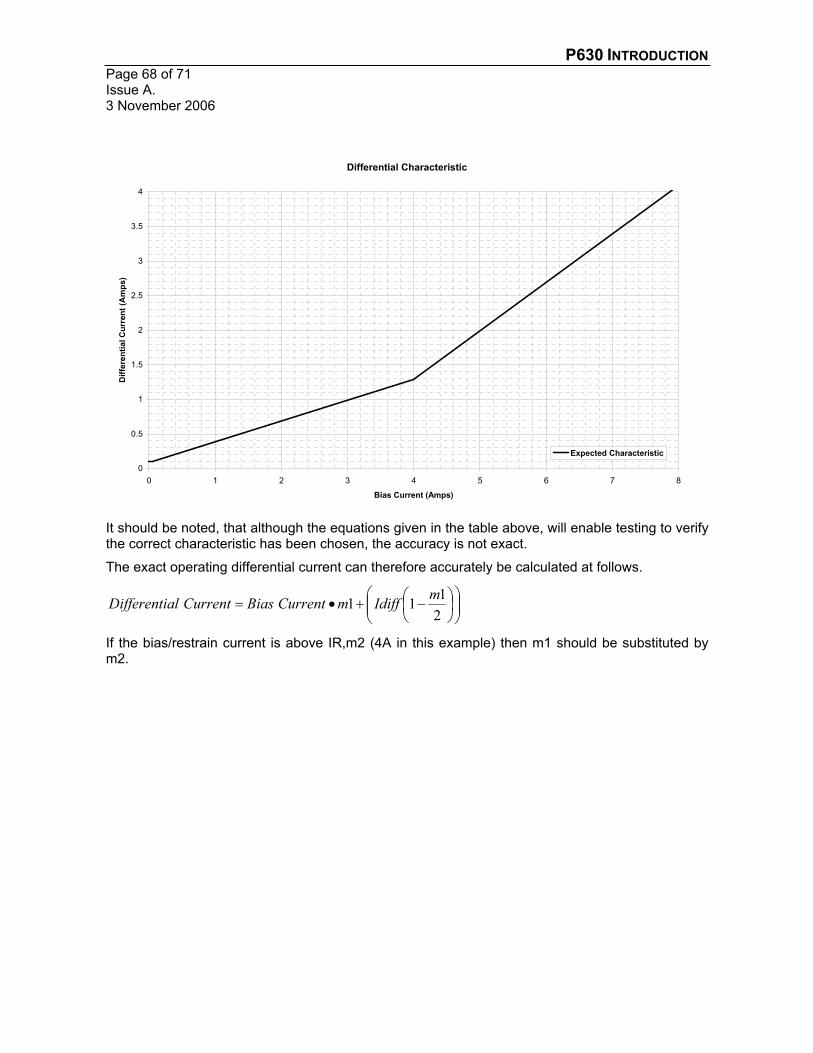
If the test has been performed correctly, the recorded results should closely match those shown in the following graph. The plot clearly shows that the relay increases it setting, as the through fault current increases, thus minimising the chances of mal-operation due to CT saturation.
P630 INTRODUCTION Page 68 of 71Issue A. 3 November 2006
Differential Characteristic
0
0.5
1
1.5
2
2.5
3
3.5
4
0 1 2 3 4 5 6 7 8
Bias Current (Amps)
Diff
eren
tial C
urre
nt (A
mps
)
Expected Characteristic
It should be noted, that although the equations given in the table above, will enable testing to verify the correct characteristic has been chosen, the accuracy is not exact.
The exact operating differential current can therefore accurately be calculated at follows.
2111 mIdiffmCurrentBiasCurrentalDifferenti
If the bias/restrain current is above IR,m2 (4A in this example) then m1 should be substituted by m2.

P630 INTRODUCTION Page 69 of 71
Issue A. 3 November 2006
11. MISCELLANEOUS
11.1. ZERO SEQUENCE FILTERING For earth fault transformer winding(s), zero sequence filtering is enabled by default and it is essential to prevent tripping for external earth faults.
It is only in the case of isolated transformer windings were no filtering is required, this is because for internal faults, no zero sequence current can flow in either side of the transformer, hence there is no danger of mal-tripping. On the other hand, for external single phase faults, zero sequence current when not filtered will be seen at one side, but this is the case when we do want the relay to trip, as it is an external fault.
In case of resistive faults it is better to disable filtering, which will increase relay sensitivity by adding Io back into the measurement quantity, which reduces the amount of phase current needed for tripping.

P630 INTRODUCTION Page 70 of 71Issue A. 3 November 2006
11.2. VECTOR GROUP MATCHING FACTORS Factors for single end, one phase feed in phase A, zero sequence filtered.
Transformer end a b, c or d
Vector Group ID - 0/12 1 2 3 4 5 6 7 8 9 10 11
DIFF: Diff. current 1 0.67 0.67 0.58 0.33 0.00 0.33 0.58 0.67 0.58 0.33 0.00 0.33 0.58
DIFF: Diff. current 2 0.33 0.33 0.00 0.33 0.58 0.67 0.58 0.33 0.00 0.33 0.58 0.67 0.58
DIFF: Diff. current 3 0.33 0.33 0.58 0.67 0.58 0.33 0.00 0.33 0.58 0.67 0.58 0.33 0.00
Factors for single end, two phase, phase opposed feed in phases B to C, zero sequence filtered.
Transformer end a b, c or d
Vector Group ID - 0/12 1 2 3 4 5 6 7 8 9 10 11
DIFF: Diff. current 1 0.00 0.00 0.58 1.00 1.15 1.00 0.58 0.00 0.58 1.00 1.15 1.00 0.58
DIFF: Diff. current 2 1.00 1.00 1.15 1.00 0.58 0.00 0.58 1.00 1.15 1.00 0.58 0.00 0.58
DIFF: Diff. current 3 1.00 1.00 0.58 0.00 0.58 1.00 1.15 1.00 0.58 0.00 0.58 1.00 1.15
Factors for single end, one phase feed in phase A, NOT zero sequence filtered.
Transformer end a b, c or d
Vector Group ID - 0/12 2 4 6 8 10
DIFF: Diff. current 1 1.00 1.00 0.00 0.00 1.00 0.00 0.00
DIFF: Diff. current 2 0.00 0.00 0.00 1.00 0.00 0.00 1.00
DIFF: Diff. current 3 0.00 0.00 1.00 0.00 0.00 1.00 0.00
Factors for single end, two phase, phase opposed feed in phases B-C, NOT zero sequence filtered.
Transformer end a b, c or d
Vector Group ID - 0/12 2 4 6 8 10
DIFF: Diff. current 1 0.00 0.00 1.00 1.00 0.00 1.00 1.00
DIFF: Diff. current 2 1.00 1.00 1.00 0.00 1.00 1.00 0.00
DIFF: Diff. current 3 1.00 1.00 0.00 1.00 1.00 0.00 1.00

P630 IntroductionPage 71 of 71
Issue A. 3 November 2006
VERSION CONTROLIssue Author(s) Reason for change Date
A.1 A Hill Original 15-02-2005A.2 C Smith Reformat and extension of material 03-05-2005A.3 C Smith Corrected the watchdog settings 25-05-2005

� � ������������
�
������������� ������� ��������������� �����
� � ������������������� ����������������������������� �������������������� � ����������������������� ������������� ������ �!�����������������"�����������#����$�
�
�
�
���������
�������!��������������������%!�����!����������������� ���������������� ����������������������&''����� ����������� � ��������������������� ����$����������������������������������
���

� � �����(������
������������ �� ����
�$� ���)� �*��� ��
($� �+ *��,����)�+ *�)���
'$� ��������� � �- *)���� �������
.$� �)� �*��/�01�
2$� �� �)������� *���� ����1�1�
&$� )�1�)�������)�/� �*��� *���� ������1�1�
$���������������� 3�) �*4� *���� ������1�1�
�
5$� � �6�� �����1�1���

� � �����'������
�� � �������� �
���� �����7���� !���������� ���� 7������� ���� ��� ����������� ���� � ���� !����������������������������&''����� ����������� � ��������������������� ����$����������� ����������� � ����� ��� ��� �� ��� !����� ��� � ���������� !��������� ���� ��������� ��������� ���7���� !������ ���� ��� � ���������� ������ ��� ������������ 7���� ���� ��� � ����������������������������#����� �����$������� ����� ����������������� ������ ��� �� ��������� ���� � ��� ����� ���� ������������ ������������8� ���� ��������9��&''���������$������!����������7�����������������#����������� ����� ��������� ������������ ��� �������� ��������� ��� ��:������ ���� �������� �� !������������������$� ����!����������������!!������������� �������������������7����������������������!!����������!���������������$����� �������������� �� !�"�#� �#"� ��!��$%&�'�� "%"��"( ��"� ! %'�) "���� �$���*"#��"��+�! ��"�#�,���# � �,��'��� �'�������� %��!�) %%��!��"���������% �! �� ' ������ % *����! ,�"��!�"���� ����- ������� �������
.� �/ � ���� �����/ � ����
�
�$��������!��������� ����������;����� � � ������,�2&<(2&� �($����������,����� �����������������������

� � �����.������
��0 � �������� ��1 � ����� �
��� ������� ����� ��
� ��������� ���� �������$�3������� 4='�� �>(�2 "�&"�#�3��� � ���������� 4='�� '>.��������?� � 2>&�������� � � >5���������� � @>�=�2 "�&"�#3.� � ����������� 4=2�� �>(��������?� � '>.�������� � � 2>&���������� � >5�2 "�&"�#3�� � ����������� 4=�� �>(��������?� � '>.�������� � � 2>&���������� � >5���) ��!$��%4� 4(=�� (28A 9>(&869�� !�����!��6�� 4(=�� �58A 9>�@869�� !�����!��6(� � (=8A 9>(�869�� !�����!��6'� � ((8A 9>(.869�� !�����!��6.� � ('8A 9>(.869�� ��!������� 6�80�5=�9� 4�5�� 8�>(6.>26�98'>(6&>26�� 9�� ��!������� 6�80�5=(9� � 8>56�=>��6�98@>56�(>��6�� 9�� ��!������� 6�80�5='9� � 8�'>�.6�2>�6�98�2>�.6�5>�6�� 9�� ��!������� 6�80�5=.9� � 8�@>(=6�98(�>(=6�� 9�� ��!������� 6�80�5=29� � 8((>('6�98(.>('6�� 9�� ��!������� 6�80�5=&9� � 8(2>(&6�98(>(&6�� 9�� ��!������� 6�80(==�9� 4(=�� 8�>(�B�� 9�8'>.�6��� 9�� ��!������� 6�80(==(9� � 82>&�B�9�8>&�B�� 9�� ��!������� 6�80(=='9� � 85>@�B�� 9�� ��!������� 6�80(==.9� � 8�=>���B�� 9�� ��!������� 6�80(==29� � 8�=>�(�B�� 9�� ��!������� 6�80(==&9� � 8�=>�'�B�� 9�� ��!������� 6�80(==9� � 8�=>�.�B�� 9�� ��!������� 6�80(==59� � 8�2>�&�B�9�8�>�&�B�� 9������

� � �����2������
��. ������ ����������� 1 ��
����� �������� ��������� ����� ���� � ���� � �������,�� ,� 1�� ��� �������� ���� ���� � 7����� ��� 1��)�� �!����� 8� !�������<������� ���� �������<,���<���� �������� B��%�����9$� ���� ���1��)�C���������,����!���������>�����������������$�������� ���1��)��>�D����������#���E���� ����������� ���������D����� E������������F���$��������������� >�������� !�������<������������������<,�G)<)���������������B��%�����$��
? � �������>� ���� ���:���� � ��� ���� ��� 2=� /"$� ������ ����� ��� &=� /">� ��� ��:�����$�8����� �����< ��������!���� �����<- �����<,���<���� ��������:$� ��� �B�2=�/"����&=�/"9�
���
5�0 ��������- ��6��
5����� ��2 ���� ����������������!�7����!>�����F����������������������!$�����������%����� �#�����������!!����>�����F��������� ����������������D/����� �8/�9E�����D� ���������#����8/(9E��������!$��������!!��%$��2�����������&''�������� ������!�������$����F������D,�� ,��&''E�������!�� ������������������������������ ����!�� $��
5�. � �� ������3����������
�����!��6�����������!�������� ���������������������� �� �����������������!������ ����� � ��!!� $� ���� ������� ��� ����� �!��� ��!��� ���� ��� #��7��� ��� � !�������< ������ ������� ����<�� �$�1������������<���$�������������!��������!������������D����E$��
�
5�� ����� ��������
����� ����� ����F�� ����� ���� ���!��� ���� �� ���� �!�������� �������� $� - �� ���� !�������<������������������<� *��$�1�������������� ��������!�������8�$�$�0�5=�9�1������������!�����D)��� �������$� $�����E�����D ��$�������� $�0�5=�E$�1������������!�����D)��� �����E����D�%�����E$��������!������� ���� ������!������������������ ���������D/���6��� ����������E������!����$�����F������!���������������������������� ������������������ �������$�)�!������������������������!������� �$�
�
�
�
�
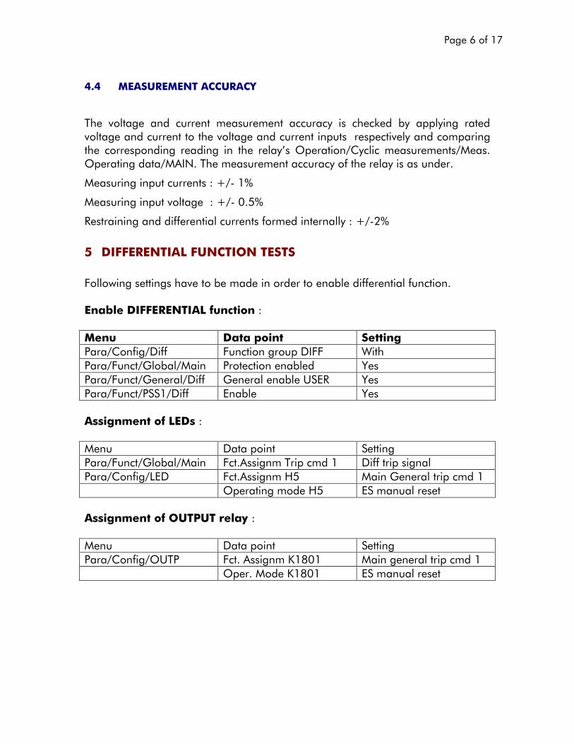
� � �����&������
5�5 ��������� ����������
�
���� #������� ���� �������� � ������� ���� ������� � ��� ����F��� � � �!!� ���� ������#��������������������������#���������������������!��������!����#�� �������� !���������� ������!������� �������� ��� ���� ���� H�� � !�������< ����� � ������� ����<,���$�� !������������<,���$������ ������� ����������� ������������ ������������$�
,�����������!������������;�A <6��I �
,�����������!���#��������;�A <6�=$2I �
)����������������������������������������� ������������ �;�A <6(I �
7 ������ ������� ���� ��������
����7���������������#��������� ��������������������������������������������$������8% ������� �����'$�,�"���;���� �$� ������"��� � ��"�#�����<�����<����� ������������!��� �� J��������< ����<- �����<,���� ������������������� K�������< ����<- ������<����� - ��������������*1�)� K�������< ����<�11�<����� �������� K�����!!"#�� ����'���!�;��,���� �����!����� 1�����������< ����<- �����<,���� ��$������� ����!��� ���� ��������!������������<�����<���� ��$������� �/2� ,����- ����������!��� ����� � !��������� ����/2� �1�� ���������������!!"#�� ����'��� ��� ��� %�4�;��,���� �����!����� 1�����������<�����<� *��� ��$�������� �0�5=�� ,���������������!��� ����� � !��$�,����0�5=�� �1�� �������������������

� � �����������
7�� ���6�� �������
7������"�#% �!"& +������! �' &���� ���������������'�!���������>����������������������������������������������������F��������������!!���������������������������&''�����������������������������#����������7� ������F������$�����������������7������&''����!���������������6��������������������������������7�$����L �8������M �N����� $"�9�<�0�� $"��O�������;���������� ��������>������������M �;������!������#�����8��������#�����B�=$(=�����9����� $"�;���� ���������������������&''�������������� ��������>�������8��������#�����6�
����������������9�0�� $"�;��� !������6� ��������������������������� ��������>�������8��������#����6��$=�
������������9��� ���&������P����������=$����B�'�!����������7��������$�- ������� ������������������������������� ��!������$�+ *�0�,�� �����������������$��
+��� ������ ���!��� ���� >� ��� ��� ���� � ���� D� !�������<������� �����������<� *��<)�����������*1�)�B��%�����E�����#�����������������!������� ����������������>�� �F���������6�����$�1������������!�����D� !��$� ,���� 0�5=�E� ��� � D����� �����<������ !���� �����<� *��E� ��� D�1�*!������E�
+������������������������>�!������������DE$���)�!�����������������7��������?����� $�����!!�,�"� �"��������F����������� ���������!�������������������7������A <62I �������������������#�����>��$�$�=$�@6=$(���$��������

� � �����5������
7���.��"�#% �!"& +������! �' &���� ���������6��������6!���������7�6!���������>���#����������!6� �����������������������������7������������#����������!��� ���������������F������������������������������������� !�������� ��������������$�������!��������������������������������������7�$���L �8������M �N����� $"�9<8�0�� $"�N�0�$ $"9��O�������;���������� ��������>������������M �;������!������#�����8��������#�����B�=$(=�����9����� $"�;���� ���������������������&''�������������� ��������>�������8��������#�����6�
����������������9�0�� $"�;��� !������6� ��������������������������� ��������>�������8��������#����6��$=�
������������9�0�$ $"��;�3����������!�� ���������������8���������� ,,�11�� ���- �1���� �������/�����,��*����������������$������������>�������=$&9��� ���&������P����������=$(5���B��������!����������7��������>�!����6�$�- ������� ������������������� ����� ���� ���� � �!������$� )�!���� ���� ����� ���� ������ !������ ���� ����� ������7�������$�+ *�0�,�� ������������������$����!!�,�"� �"��������F����������� ���������!�������������������7������A <62I �������������������#�����>��$�$�=$(5'6=$'�'��$�����������������

� � �����@������
7�.��� ������- ���������������
7�.��� ��2 ���������
� ��"�#!����� ������������>����!�������7������������$���� �$� ������"��� � ��"�#�����< ����<�11�<����� =6��:�����$�����$� �������< ����<�11�<����� =6��:�����$�?���$� �������< ����<�11�<����� =6��:�����$� ���$� �������� ,�"��!���������������������������������!�����������������������!!� ��7����������>���������!����6�>�7������6��8��9����������������!����6�>�7������6?�8��9$�?��������������������������!������!!�������$��� ���&�����P�����������7������������7�������7�������?$�- ������� ����������7������6?������������������ ��!�������$��������7��#����$�+ *�0�,�� �����������������$�)�!�����������������������!��������!���������7���������Q�?$�����>���!���������������������������!�����!���������7���������Q� $�����!!���"� �"����)�����������������������L �=$2�N�R�S��S�A �S��S�T�� � � 6666666666��8�9��������������������������L �S����A ����S� � � � 6666666666��8��9��
���������������:�������������7������!��8�7����=$2������M �U ���™���>� (�9�
���L �8� �N��9�A �8�����M 9N8�6=$2� �9�� � � � 66666666666�8���9���������������>�� �������L ��=$'�� � �����M ��L ��=$(���8�����������������D��E�����D��E���������#���� ��������� ��������� !�����������#����������!�� �������$�/����>�7����#������ ����!� ���P���������������� ��� !�������� �����������������������������������D��E�����D��E$��������������� !�������� �������������������$=����������7�������>�����������������������:�����9�

� � ������=������
����������#��������D��E����� ������:�������8�9$�*����������#��������D��E>�����������������������#��������D��E����� ��:�������8���9$������������������������8�9������������ ��������#��������D��E����� ��:�������8��9������������8?9�� �
+����F����������D� ��������#�����������������������������8?9E������7������A <6�2I ��������D������������#�����������������������������8�9E��
7�.�.� � ������������
����� ,�"��!���������������������������7������!�$��� ���&�����P����&�����������!����6�����7������6��8��9�$���P�����!!��%$�.$(������!����6�����7������6?�8��9$�- ������� ���������������������� ��!�������$��������7��#����$�+ *�0�,�� �����������������$�)�!�����������������������!��������!���������7���������Q�?$�����>���!���������������������������!�����!���������7���������Q� $�����!!���"� �"����)�����������������������L �=$2�N�R�S��S�A �S��S�T�� � � 6666666666��8�9��������������������������L �S����A ����S� � � � 6666666666��8��9��
���������������:������������!!������!��87��������M ���>� (9�
���L �� (N���A ������M 8�6=$2� �9�A �.N8� �6� (9� � � 66666666666�8���9� �������������>�� ������L ��=$'�� � ,(� L ��=$��� � �����M ��L ��=$(�� � ���� (���L �.$=����

� � �������������
�����������#��������D��E����� ������:�������8�9$�*����������#��������D��E>�����������������������#��������D��E����� ��:�������8���9$������������������������8�9������������ ��������#��������D��E����� ��:�������8��9������������8?9�� �
+����F����������D� ��������#�����������������������������8?9E������7������A <6�2I ��������D������������#�����������������������������8�9E��7��� �������� 1 ��������������� ���������� ���� ���&�������P���������������!����������������!����6�����7������6�$��������7���!����������� ���������������������� ���$��)�!�����������������������!����������������7�������$����!!�,�"� �"���������� ���������!����������� ������������� !����� �''�� ����7�5� ����� �- ���� �������6� 1 ��� ����7����������������������������������� ���������F������,����� �����!����� 1���������������%�� !�������< ����<�11�<����� )�����8(�=9<��8�=9��1�� (=I ������ ,�"��!�����1������!�������������������������P���������>��� >��6!��������7������6�$���� !��� ���&�;��������� ������B��� �)�������*���D���� ����E����$��1����������������� �������P�������1������ ������L ��$=��<���� �%����L ��U (=I �>��� ��@I>������#��������� �)����������� ����������� ����!�$�� �%����L ��M (=I �>��� �(�I>������#��������� $����� ���������H�����!���

� � ������(������
��!!�,�"� �"��;�����,������������������� �����������������������F������������������������ ��������������A <62I ��������#����$��7�7� �����- �- ���� �������6� 1 ������!�������7������������������������������������ ���������F���$��,����� �����!����� 1�������������< ����<�11�<����� ����$�� #�����%���$���� K���� � #����82�=9<8�=9� (=I ������ ,�"��!�����1������!�������������������������P���������>��� >��6!��������7������6�$���� ���&�;��������� ������B��� �)�������*���D���� ����E����$��1���������������� �������P�������1������ ������L ��$=��<���� �%����L ��U (=I �>��� ��@I>������#��������� �)����������� ����������� ����!�$�� �%����L ��M (=I �>��� �(�I>������#��������� $����� ���������H�����!����!!�,�"� �"��;����,������������������ �����������������������F������������������������ ��������������A <62I ��������#����$��7��� ��- ��6� 1 �����&"''�9 9 ���,���� ������7�����������������������������!���8����6���9��������������!������������������$���,����� �����!����� 1������������< ����<�11�<����� ������M M ���1�� 2$=�����������

� � ������'������
� ���&�������P�����=$=����������!����������������!����6�����7������6�$��������7���!����������� ���������������������� ���$��)�!�����������������������!����������������7�������$����!!�,�"� �"���������� ���������!����������� ��7�������� ���������F������������������������ !����� �(�� �$���7�:� ��- ��6� 1 �����&"''�9 9 9 ���,���� ������7�����������������������������!���8����6���9��������������!������������������$���,����� �����!����� 1������������< ����<�11�<����� ������M M ���1�� �2$=������� �����M M M ��1�� 2$=�������� ���&�������P�����=$=����������!����������������!����6�����7������6�$��������7���!����������� ���������������������� ���$��)�!�����������������������!����������������7�������$����!!�,�"� �"���������� ���������!����������� ��7�������� ���������F������������������������ !����� ��2�� �$���������������

� � ������.������
� ��������������� ��� �����������
� ����7���������������#��������� �����������������������)� ���������$������8% �����'$�,�"���;���� �$� ������"��� � ��"�#�����<�����<)� G�� ������������!�)� G�� J��������<�����<)� G(� ������������!�)� G(� J��������<�����<)� G'� ������������!�)� G'� J��������< ����<- ������<)� G�� - ��������������*1�)� K�������< ����<- ������<)� G(� - ��������������*1�)� K�������< ����<- ������<)� G'� - ��������������*1�)� K�������< ����<�11�<)� G�� �������� K���� � !��������� ���� /������ !�����������< ����<�11�<)� G(� �������� K���� � !��������� ���� /������ !�����������< ����<�11�<)� G'� �������� K���� � !��������� ���� /������ !�����������< ����<�11�<����� �������� �����!!"#�� ����'���!�;��,���� �����!����� 1�����������< ����<- �����<,���� ��$������� ����!��� ���� ��������!�������>)� G�����!�
������>)� G(����!�������>)� G'����!��������
����<�����<���� ��$������� �/2� ,����- ����������!��� ����� � !��������� ����/2� �1�� ���������������!!"#�� ����'��� ��� ��� %�4�;��,���� �����!����� 1�����������<�����<� *��� ��$�������� �0�5=�� ,���������������!��� ��������� ���6�� �������������� ,�"��!�����1������!������������������������P����������������������������������������7������6��84='��B�@>�=9��

� � ������2������
���� ���&�������������������P����������������������� ��!�������$�+ *�0�,������������$����!!�,�"� �"���������F�������������� ��!�������7������A <6�2I ����=$(��$�����. ������� 1 ������������������ ���� ���&�������P���������������!�����������������������������������������������7������6�$��������7���!����������� �����)� G������ ���$�����!!�,�"� �"���������� ���������!����������� ������������� !����� �(2�� �$���
� ������ �� �����������
� ����7���������������#��������� �����������������������)� ���������$������8% �;<'�'$�,�"���;���� �$� ������"��� � ��"�#�����<�����<3<�� ������������!�3<�� J��������< ����<- ������<3<�� - ��������������*1�)� K�������< ����<�11�<3<�� �������� K������������
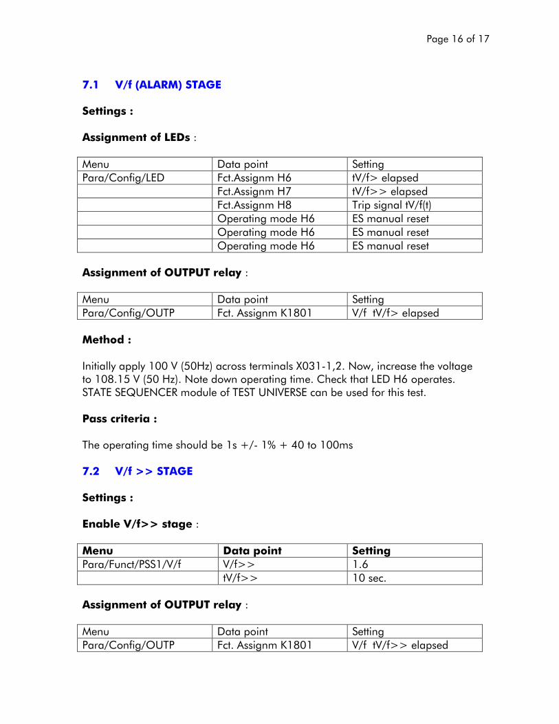
� � ������&������
:��� ;<'�=�����>����1 ���� ��"�#!�����!!"#�� ����'���!�;��,���� �����!����� 1�����������<�����<���� ��$������� �/&� �3<�M ����!����� ��$������� �/� �3<�M M ����!����� ��$������� �/5� ���!���������3<�8�9��� � !��������� ����/&� �1�� ������������� � !��������� ����/&� �1�� ������������� � !��������� ����/&� �1�� ���������������!!"#�� ����'��� ��� ��� %�4�;��,���� �����!����� 1�����������<�����<� *��� ��$�������� �0�5=�� 3<����3<�M ����!������ ���&������������ ��!!� ��==�3�82=/"9������������ ������4='�6�>($���7>��������������#�����������=5$�2�3�82=�/"9$��������7���!����������� �$����F��������� �/&��!������$�1�����1�+ *���)�� �����������1��*��3�)1���������������������������$�����!!�,�"� �"����������!����������� ���������������A <6��I �A �.=�����==� ���:�. ;<'�9 9 ����1 ���� ��"�#!�������8% �;<'9 9 �!��# �;���� �$� ������"��� � ��"�#�����< ����<�11�<3<�� 3<�M M � �$&�� �3<�M M � �=����$���!!"#�� ����'��� ��� ��� %�4�;��,���� �����!����� 1�����������<�����<� *��� ��$�������� �0�5=�� 3<����3<�M M ����!����
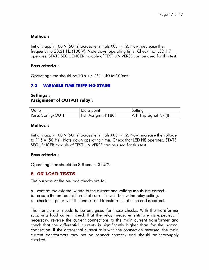
� � ������������
�� ���&������������ ��!!� ��==�3�82=/"9������������ ������4='�6�>($���7>�����������������:���� ����'=$'��/"�8�==�39$��������7���!����������� �$����F��������� �/��!������$�1�����1�+ *���)�� �����������1��*��3�)1���������������������������$����!!�,�"� �"������ !����������� �������������=���A <6��I �A .=�����==� ���:��� ;������������������� 1 ����1 ���� ��"�#!����!!"#�� ����'��� ��� ��� %�4�;��,���� �����!����� 1�����������<�����<� *��� ��$�������� �0�5=�� 3<������!���������3<�8�9��� ���&������������ ��!!� ��==�3�82=/"9������������ ������4='�6�>($���7>��������������#������������2�3�82=�/"9$��������7���!����������� �$����F��������� �/5��!������$�1�����1�+ *���)�� �����������1��*��3�)1���������������������������$����!!�,�"� �"������ !����������� ������������5$5����$�A �'�$2I �
� ����������
����!��!�������������6���������F��������;���$ ������� ������%�������7�������������������������#���������!���������������$��$ �������������6�����������������������������7��������7��������� ��������$��$ ����F�����!������ ������������������������������ ��������������������������$������ ��������� ��� ������ ��� ��� ���������� ���� ������ ����F�$� J���� ���� ��������� �����!!� ���� ����� �������� ����F� ����� ���� ���� � � ������� ����� ���� ��� �%!�����$� ����������� >� ��#����� ���� �������� ������������ ��� ���� � ���� �������� ��������� ��� ��������F� ����� ���� ������������� ��������� ��� ������������ � ������� ����� ���� ���� ���� �������������$�����������������������������������7���������������������#�����>������ ������������ ��������� ���� � � � ���� ��� �������� �������� � ���� ������� ��� ��������� �����F��$�

Commissioning & Maintenance of Protective Relaying Equipment

AREVA EAI Preference
� Primary injection
� Secondary injection
� On load tests
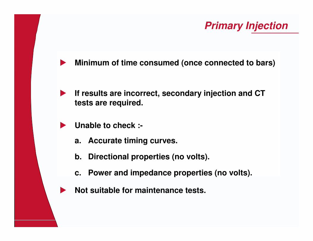
� Minimum of time consumed (once connected to bars)
� If results are incorrect, secondary injection and CT tests are required.
� Unable to check :-
a. Accurate timing curves.
b. Directional properties (no volts).
c. Power and impedance properties (no volts).
� Not suitable for maintenance tests.
Primary Injection

Secondary Injection
� Obtain correct relay characteristic for setting values.
� Reference for maintenance tests obtained.
� Relay if necessary can be tested with the system on load, due to test block isolation.

On-Load
� Checks that expected C.T. / V.T. quantities are present at the test facility
� Scheme stability for external faults
� Proof of correct directional characteristics

Why ?
� To assure ourselves, and the interested authorities, that the overall protective system functions correctly
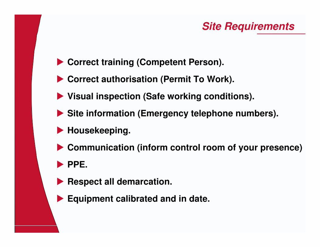
Site Requirements
� Correct training (Competent Person).
� Correct authorisation (Permit To Work).
� Visual inspection (Safe working conditions).
� Site information (Emergency telephone numbers).
� Housekeeping.
� Communication (inform control room of your presence)
� PPE.
� Respect all demarcation.
� Equipment calibrated and in date.

Pre Commissioning Primary
� Insulation Tests
Meggar 500/1000 VdcFlash Testing (LV switchgear) 2.5kV @ >1 min

Commissioning Primary
� Primary injection tests
D.C. flick tests on C.T.’s
C.T. mag curve tests
C.T. ratio and polarity tests
Primary sensitivity tests
Stability tests
Test results

Commissioning Secondary
� Secondary Injection Tests
Visual Inspection. (remove all packing.. etc)
Check out-going contact wiring.
External resistors.
C.T. shorting and isolating switches.
Electrical checks on each basic electrical function to prove satisfactory operation.
Prove trip and alarm circuits.
Test results (record and maintenance purposes).

Commissioning On-Load
� Line , Transformer or Generator energised
V.T. ratio and phasing tests
On load tests
Stability tests
Directional properties

Commissioning Summary
� At the end of each stage ask yourself :-
Is there anything wrong, wiring or otherwise, that I have not checked that may prevent correct operation????
� If so:-
CHECK IT OUT !!!!

Frequency of Maintenance
� Dictated by :-
The site conditions.
The availability of maintenance staff and resources.
The availability of plant outage times.
The risks involved if the protection should fail.
The type of relay construction.

Frequency of Maintenance
The proven reliability of devices under identical site conditions.
The availability of built-in self-check features or semi-automatic test facilities, and the difficulties of alternative tests.
The interval of time an unexpected catastrophic failure, component or otherwise, that may go undetected and leave the system unprotected.

Frequency of Maintenance
Onerous site conditions :-
Dusty or dirty environments.Corrosive chemical atmospheres.Frequent or continuous vibration.High humidity.High or cycling temperatures.Consistently high levels of energising or auxiliary quantities.
Typically maintain every 1 - 5 years under ideal conditions and decrease frequency

Maintenance Checks
� Visual inspections
At each maintenance test
After heavy fault clearance
More regularly if onerous site conditions
� Calibration tests (electo-mechanical Only)
� Trip testing

Current & Voltage Transformer
� Flick tests� Ratio checks� Magnetizing Curve� Phasing Checks� Primary Injection

Current Transformer Polarity Check
�������� ��������
���������������� ��������
���������������� ���� ���� ���� ��������������������
����������������������������
������������

Current Transformer Ratio Check
�������������������������������������������������������� ������������
��������
�������� ��������
����������������
���� ����� ������ ���� ����� ������ ���� ����� ������ ���� ����� ������ ��������������������������������
��������������������������������������������������������
����������������! ����������������! ����������������! ����������������!�� �����"� #������ �����"� #������ �����"� #������ �����"� #����
��������
$�������#$�������#$�������#$�������#� ������� � ������� � ������� � �������
%&%&%&%&
��������
��������
$�� ������$�� ������$�� ������$�� ��������������������������������������������������

Testing Current Transformer Magnetizing Curve
�������������������������������������������������������� ����
����������������
��������
��������
����
$�������#�������� #$�������#�������� #$�������#�������� #$�������#�������� #����� ����� �"��� �������� ����� �"��� �������� ����� �"��� �������� ����� �"��� ���"��� ������������"��� ������������"��� ������������"��� ������������
������������������������������� �"��� ����� �"��� ����� �"��� ����� �"��� �������'������'������'������'�
����������������������������������������������������
�������������������������� �"��� �������� �"��� �������� �"��� �������� �"��� ���"���(����)�"���(����)�"���(����)�"���(����)
* �� ��������* �� ��������* �� ��������* �� �����������!������ ���!������ ���!������ ���!������
$�������$�������$�������$���������������������������
����

Voltage Transformer Phasing Check
������������
��������
��������
����++++
����,,,,
����
������������������������������������������������ ������������ ������������ ������������ ������������ � ����� ����� ����� ����
����
��������
��������
��������

Primary Check on Main Current Transformers
$�� �����������$�� �����������$�� �����������$�� �����������������������������������������������������������������������������������
���� ������� ������� ������� ���� ������ � ������ � ������ � ������ ��������������������������������
�����������������-�-��������-�-��������-�-��������-�-�������
����
����
����
��������
��������
��������
%&%&%&%&���������. /������� ������������. /������� ������������. /������� ������������. /������� �������%&���0����"����������%&���0����"����������%&���0����"����������%&���0����"������������������ � ������������ � ������������ � ������������ � ����

Sensitivity Test on Earth Fault Relay
��������
��������
�����������������-�-�-�-�-�-�-�-������������������������
����
����
����
��������
%&%&%&%&
���� ����� ������ ���� ����� ������ ���� ����� ������ ���� ����� ������ ��������������������������������

Incorrectly Maintained Equipment
� 60MW Steam Generator at Uxmouth Power Station, South Wales. 1960.

Incorrectly Maintained Equipment
� Some time later� An engineer was
working on adjacent generator
� Removed excitation of this generator by accident
� Generator started to speed up
� Governors should have come out but jammed
� Steam valve should have operated but rusted solid
� No other protection
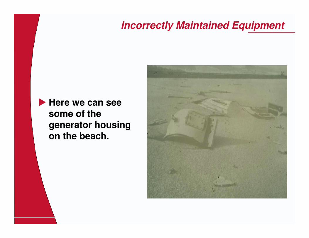
Incorrectly Maintained Equipment
� Here we can see some of the generator housing on the beach.
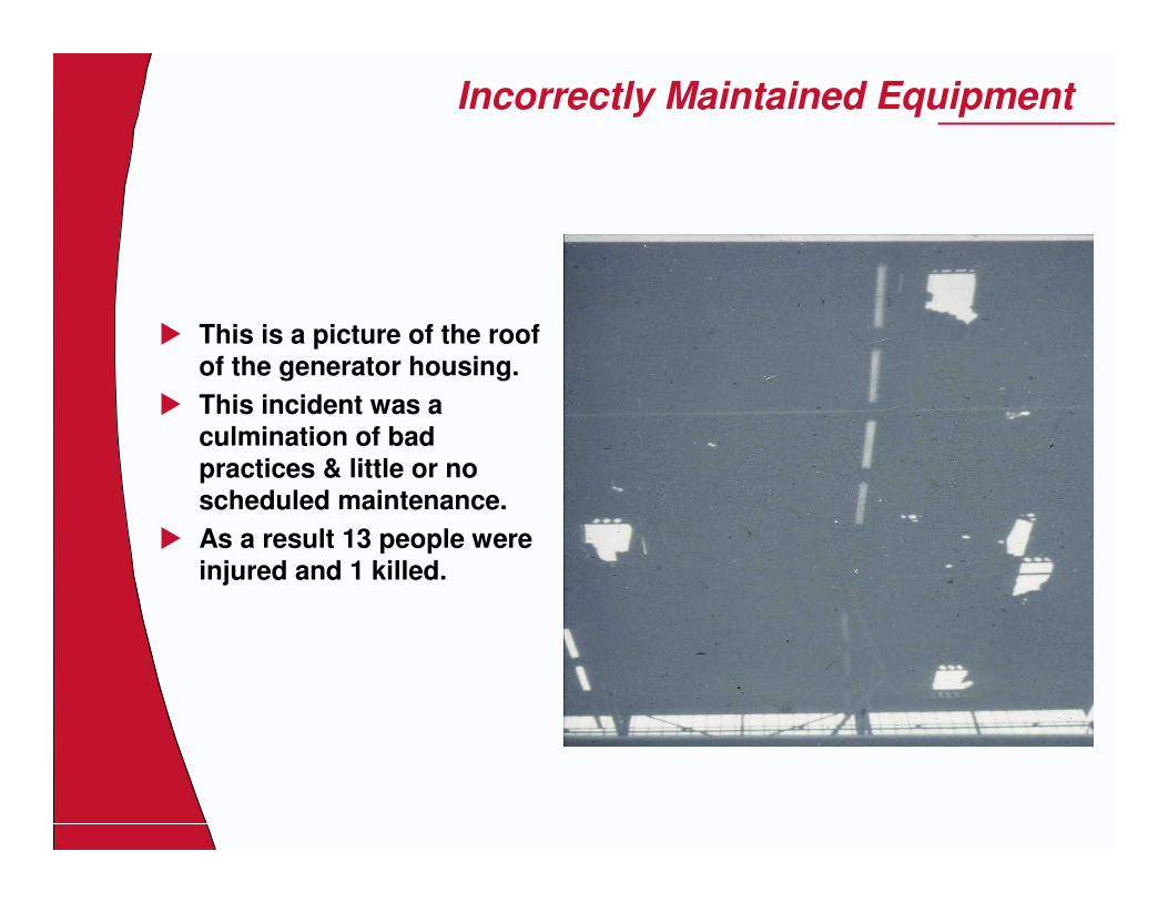
Incorrectly Maintained Equipment
� This is a picture of the roof of the generator housing.
� This incident was a culmination of bad practices & little or no scheduled maintenance.
� As a result 13 people were injured and 1 killed.

1 1
Maintenance & Equipment Failures- MiCOM

2 2
Maintenance
AREVA protective relays are designed for a life in excess of 20 years.
� MiCOM relay is self-supervising and so requires less maintenance than earlier designs of relay. Most problems will result in an alarm so that remedial action can be taken. However, some periodic tests should be done to ensure that the relay is functioning correctly and the external wiring is intact.
- i.e Periodic Functional Checks, locally at the Substation

3 3
Maintenance
Maintenance Checks:
� LEDs� Opto Isolators� Output Relays� Measurement Accuracy:
- The values measured by the relay can be checked against known values, which points to the analogue/digital conversion and calculations are being performed by the relay.
These tests will prove the calibration accuracy is being maintained.

4 4
Problem Analysis
Equipment Errors/Faults:
The MiCOM relay is fully Numerical and performs constant self-diagnosis. Any failure of software or hardware elements is instantly detected. As soon as an internal fault is detected, depending on its type (minor or major), an alarm message is displayed as a priority on the front panel LCD before the fault LED is illuminated and the watchdog relay is closed (if the fault is a major one).
Only the disappearance of the cause will acknowledge the fault and hence reset the fault LED.

5 5
�Minor Faults
�Message:
� "COMM.ERROR": Control communication faulty� .RAM ERROR. : Battery backed RAM faulty� .BATTERY FAIL.: Battery faulty or flat.� .COMMS ALARM CH1.: communications channel
failure detected.
Problem Analysis
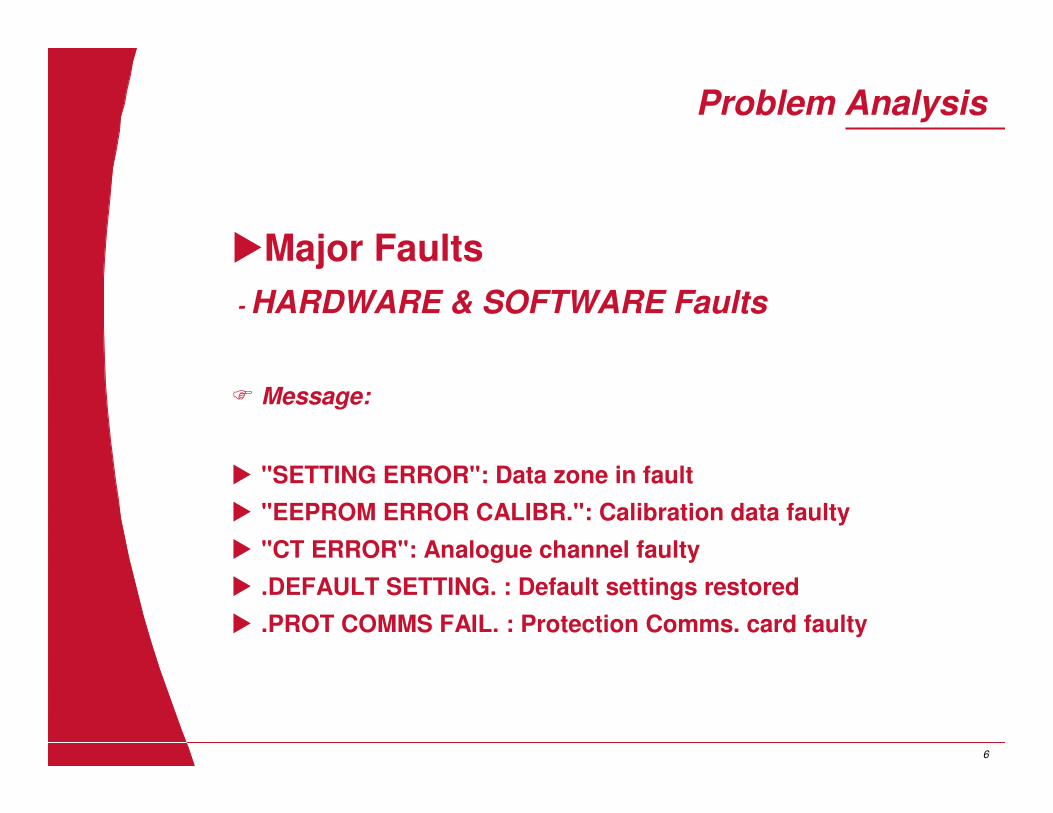
6 6
�Major Faults- HARDWARE & SOFTWARE Faults
� Message:
� "SETTING ERROR": Data zone in fault� "EEPROM ERROR CALIBR.": Calibration data faulty� "CT ERROR": Analogue channel faulty� .DEFAULT SETTING. : Default settings restored� .PROT COMMS FAIL. : Protection Comms. card faulty
Problem Analysis

7 7
�Major Faults- HARDWARE & SOFTWARE Faults
Action :Restart the protection software by interrupting the auxiliary supply for approximately ten seconds. In the case of the .DEFAULT SETTING. and .SETTING ERROR. alarms the inservice settings should be re-applied.
Problem Analysis

8 8
Problem Analysis
Trouble shooting/identification tips- Error Codes
�Software related:�Error Message/codes on power-up�Out of service LED lights-up on power-up�Error Code during normal operation
Error codes – Via Front panel or Maintenance Records
�Hardware related:
�Failure of Output Contacts�Failure of Opto isolated inputs�Measurement errors of Analog signals
Error codes & meaning refer to the MiCOM Technical Guides

COMMISSIONING & MAINTENANCE PCOMM014 Page 1 of 13
COMMISSIONING AND MAINTENANCE OF PROTECTIVE RELAY EQUIPMENT

COMMISSIONING & MAINTENANCE PCOMM014 Page 2 of 13
COMMISSIONING AND MAINTENANCE OF PROTECTIVE RELAY EQUIPMENT
INDEX TO THIS SUPPLEMENT
SECTION PAGE
SITE TESTING AND COMMISSIONING OF PROTECTIVE
EQUIPMENT 1 4-8
Basic approach of commissioning 1.1 4
Mechanical inspection and ohmmeter checks 1.2 5
Insulation checks 1.3 6
General notes on measuring instruments 1.4 6
DC. Auxiliary Supplies 1.5 6
Test Equipment 1.6 6
Reference results for future maintenance 1.7 7
Faulty Relays 1.8 7
Commissioning flow-chart summary 1.9 8
A GUIDE TO RELAY MAINTENANCE 2 9-10
Frequency of maintenance periods 2.1 9
Visual inspections 2.2 9
Calibration tests 2.3 10
Trip testing 2.4 10
Recommended Maintenance tests 2.5 10
CORRECTIVE MAINTENANCE OF PROTECTIVE RELAYS 3 10
Cleaning solvents 3.1 10
Contact lubricants and other lubricants 3.2 11
Contact cleaning burnishes 3.3 11
Contact pressures and settings 3.4 11
Dust removal 3.5 11
Relay recalibration 3.6 11
Relays involving static (electronic) components 3.7 11
Modern static relays - Midos range, etc. 3.8 12

COMMISIONING & MAINTENANCE Page 3 of 13 Issue B September 1998
FIGURE 1 - COMMISSIONING TEST OPTIONS - 13
INDEX TO PROTECTIVE RELAY APPLICATION GUIDE REFERENCE
SECTION PAGE
INITIAL TESTS 23.13 397
INSULATION TESTS 23.14 397
CURRENT TRANSFORMER: 23.15 397/398
Polarity 23.15.1 397
Ratio 23.15.2 397
Magnetisation Curve 23.15.3 397/398
VOLTAGE TRANSFORMER : 23.16 398/399
Polarity 23.16.1 398
Ratio 23.16.2 398
Phasing 23.16.3 398/399
SECONDARY INJECTION : 23.17 399/407
Equipment: Test Block & Plug 23.17.1 399/400
Relays: 0/C & E/F 23.17.2 400/403
Differential 23.17.3 403
Pilot Wire 23.17.4 403/404
Negative Phase 23.17.5 404
Sequence
Directional 23.17.6 404/405
Distance 23.17.7 405/407
DC. Operated 23.17.8 407
PRIMARY INJECTION: 23.18 407/419
General 23.18 407
Relays: O/C & E/F 23.18.1 407/408
Directional 23.18.2 408/411
Generator Diff. 23.18.3 411
Transformer Diff. 23.18.4 412/414
Restricted E/F 23.18.5 414
Pilot Wire 23.18.6 414/416
Busbar 23.18.7 416/418
Negative Phase 23.18.8 419
Sequence
TRIPPING ~ ALARM ANNUNCIATION 23.19 419
PERIODIC MAINTENANCE 23.20 419/420

COMMISIONING & MAINTENANCE Page 4 of 13 Issue B September 1998
1 SITE TESTING AND COMMISSIONING OF PROTECTIVE EQUIPMENT
Reference is made to Section 23 of the "PROTECTIVE RELAYS APPLICATION GUIDE" which adequately covers the basic requirements of most main types of protection. Publications giving detailed commissioning tests on specific relays/schemes are normally available on request. The following summarises the basic approach required for commissioning and supplements the information given in "PRAG".
1.1 BASIC APPROACH The purpose of commissioning can be defined as:
"TO ASSURE OURSELVES, AND THE INTERESTED AUTHORITIES, THAT THE OVERALL PROTECTIVE SYSTEM FUNCTIONS CORRECTLY". Every basic function should be checked and nothing should be left to chance. If doubt exists as to the correct functioning of a device, it is not good enough to assume that it is probably satisfactory IT MAY NOT BE. When a new installation is planned an estimated period is made available for commissioning tests. Inevitably, the planned dates for each stage run late and the commissioning engineer is expected to make up lost time. Undue pressure to speed-up can be made if the protection fails to operate owing to, say, a wiring fault that could have been found with a simple commissioning test. Before commissioning tests are commenced one should be familiar with the overall protective layout. The procedure to be adopted for commissioning should be planned so that work is not unnecessarily duplicated. It is essential that tests should not be omitted because of ill-defined responsibilities between two or more
commissioning engineers. A number of options exist between the minimum number of electrical tests that are necessary to satisfactorily prove the protective system, and that recommended by our company. These are summarised in Fig 1 (page 13) attached with some of the advantages and disadvantages with each method. Site safety aspects cannot be too strongly emphasised. Close liaison between all commissioning, plant and switch gear engineers is essential to ensure that circuits are not made "live" by primary or secondary injection, closing of isolators, etc., without adequate concern for the safety of others. Preferably, a safety liaison
engineer should be appointed and made responsible for the safe co-ordination of all work. Basically, commissioning relative to protective switch gear includes the following:
1.1.1 Checks on wiring diagrams used by the erector:
Particular attention should be paid to over-lapping C.T. positions. A simplified "key" diagram, showing basic C.T./V.T./and relay type/positions is advisable.

COMMISIONING & MAINTENANCE Page 5 of 13 Issue B September 1998
1.1.2 General Inspection of Equipment
Check for general damage, tightness of connections, correctness of wiring and wire numbers, according to the relevant schematic diagrams and wiring diagrams.
(See Section 2 for applicable checks on relays).
1.1.3 Insulation resistance tests between all independent circuits and all circuits to earth.
"See Section 3 for further details).
1.1.4 Tests of Main Current Transformers.
C.T. ratio, polarity and magnetism - curve checks are normally recommended. Tests are detailed in Section 23 of "PRAG".
1.1.5 Tests of Protection Voltage Transformers. Ratio, polarity and phasing checks are detailed in Section 23.
1.1.6 Secondary Injection Tests on Relays. These are designed to prove the basic operation of each relay/relay scheme independently.
1.1.7 Primary Injection Tests/On Load Tests.
These are designed to prove the scheme stability for external faults and the effective current setting for internal faults. The directional properties of relays, where relevant are normally proven with the system on load.
1.1.8 Checks on Tripping and Alarm circuits.
1.2 MECHANICAL INSPECTION OF RELAYS AND SIMPLE OHMMETER CHECKS Before removing covers from relays, ensure the area is relatively free from dust - it can easily jam bearings etc., and destroy contact reliability. Typical checks that can be carried out prior to serious electrical testing include :
1.2.1 A basic mechanical inspection to ensure freedom from general damage in transit.
1.2.2 A check to ensure the right relay is fitted in the right case - Serial Numbers and Model Number.
1.2.3 A general check on tightness of links, screws, etc.
1.2.4 That the correct external resistor is fitted in the right place (where relevant).
1.2.5 The C.T. shorting switches are fitted across all C.T. circuits, and function correctly when the relay is withdrawn.

COMMISIONING & MAINTENANCE Page 6 of 13 Issue B September 1998
1.2.6 That the trip isolating switch works (lower L.H. "red" cradle latch on measuring relays fitted to the conventional draw-out case only).
1.2.7 That unit contacts wire to the right terminals. Simple ohmmeter checks to the relevant relay wiring diagram takes little time and may well prove worthwhile.
1.2.8 That contact pressures and follow thoughts are approximately correct. Pressures can be carefully assessed on accessible units with a probe (screwdriver) and compared with similar contacts on other such units.
1.3 INSULATION CHECKS
Pressure testing, for example, 2KV rms. for 1 min, has been carried out on each individual relay on manufacture. Normally insulation checks on site are limited to DC. insulation resistance checks only. Where pressure tests are required, possibly by switchgear manufacturers, either static relays should be temporarily removed, or extreme care should be taken to ensure that the voltage is not suddenly applied. Solid connections should be made and the voltage slowly increased to the required (2kV) level - held for a nominal time, then reduced to zero. In practice, site checks are preferably carried out with a 500V (or 1000V) DC. insulation tester. Where static circuitry is employed, as is often the case, a "brushless" type of insulation tester should be used, since worn brushes on the older forms of testers can promote spikes in excess of 5kV. Although the resistance of circuits to earth is often only checked, ideally each electrically separate circuit should also be checked to all other circuits. The following approach is suggested : Connect the accessible terminals of each independent circuit together. Connect all circuit groups so formed together and solidly link to earth. Isolate each circuit group in turn, removing station circuit earth links as necessary, and test between this group and all the remaining groups still linked to earth. Having checked the insulation of all circuits, ensure that all station earthing links are replaced. Insulation levels vary:- over 100 Mohms may he obtained on a small installation, but on a few Mohms where wiring is extensive. humidity is a major influencing factor and should be considered when the results are to be used as a reference for future insulation checks to detect deterioration. Care should be taken that all associated circuitry is kept clear of unauthorised personnel during the insulation tests. It should also be remembered that cubicle capacitance may maintain a reasonable charge even after the test has finished - a few seconds should be left before attempting to disconnect leads.
1.4 GENERAL NOTES ON MEASURING INSTRUMENTS Generally on site checks are not intended to be precise regarding accuracy - unavailability of suitable test equipment is often a limiting factor.

COMMISIONING & MAINTENANCE Page 7 of 13 Issue B September 1998
Instruments:- Note that errors are expressed as a % of Full Scale Deflection - a 2% instrument can have a 20% error if used at 1/10th of its scale. Instrument deflection should be kept as near full-scale as possible.
1.5 DC. AUXILIARY SUPPLIES Generally relays are designed to tolerate a maximum ripple content of 12% (peak to peak ripple as a % of the mean DC. component). Damage to the static circuitry of some relays may result if a unsmoothed supply is used. Relays should definitely NOT be energised directly off battery charges without the batteries being
connected. 1.6 TEST EQUIPMENT
Test equipment should give sinusoidal outputs and ideally should be a true replica of system pre-fault and fault conditions, especially when testing the "Distance" relays. If so, the test set can be used on any such relay with confidence, irrespective of relay manufacturer. If it does not represent the systems, results may be incorrect and confusing. The instructions of the relay manufacturer
recommending its use should be followed specifically. 1.7 REFERENCE RESULTS FOR FUTURE MAINTENANCE
Commissioning test results are often used as a reference for future maintenance checks. It should be noted, however, that consistency between such sets of results depend largely on the class of instruments that is used each time, the suitability of the test equipment/supplies and precise test conditions. To avoid having to change relay settings during maintenance, commissioning results should preferably include those taken with the relay at it's final setting - this also gives the assurance that the relay operates correctly "as left".
1.8 FAULTY RELAYS
Experience has shown that suspicions of faulty relays are often unfounded. It is easy to make a simple mistake on testing and one should first suspect the test equipment, it's wiring, the instruments involved and the method of test, especially if the latter differs from that recommended. A simple substitution of the "faulty" relay with a known "good" relay of the same type is often conclusive. Note that precautions against ESD (Electro Static Discharge) must be taken when handling the internal circuitry of any relay involving electronic circuitry (see Section 3.7).

COMMISIONING & MAINTENANCE Page 8 of 13 Issue B September 1998
1. 9 COMMISSIONING FLOW-CHART SUMMARY
Study of wiring diagrams and protection requirements. Careful delegation of responsibilties to reduce duplication of effort and ensure all the following aspects are covered.
Secondary Injection(Relays tests)
Ensure clean dust free areaMechanical inspectionOutgoing contact wiring
External resistors C.T. shorting switchesTrip isolating switchContact follow thro. & pressures
Electrical tests on each basic protection function to provesatisfactory opeation
Prove operation of trip and alarm circuits -
Test results
Primary injection
D.C flick tests on CTsC.T. Mag. CurvesC.T. Ratio & polarity
Primary sensitivityStability tests
Test results
Line / Trans / Gen EnergisationV.T. ratio and phasing
On load tests
Stability tests
Directional properties
Insulation Tests
Commissioning of Protective Relays
To assure ourselves and the interested authorities, that the overall protective system functions correctly.
AT THE END OF EACH STAGE ASK YOURSELF : "IS THERE ANYTHING THAT MAY BE WRONG, WIRING OR OTHERWISE, THAT I HAVE NOT CHECKED THAT MAY PREVENT CORRECT OPERATION?" - IF SO, CHECK IT OUT!

COMMISIONING & MAINTENANCE Page 9 of 13 Issue B September 1998
2 A GUIDE TO RELAY MAINTENANCE
2.1 FREQUENCY OF MAINTENANCE PERIODS
Any relay manufacturer, would be unwise to lay down specific recommended intervals between maintenance outages. Such recommendations in the past have put an unacceptable onus on the customer, who have sometimes been unable to comply with even an infrequent maintenance requirement. Generally, the need, and recommended frequency of regular maintenance is dictated by: a) The site condition
b) The availability of maintenance staff, and resources.
c) The availability of plant outage times
d) The risks involved if the protection should fail
e) The type of relay construction - electromagnetic or static.
f) The proven reliability of devices under identical site conditions.
g) The availability of built-in self-check features or semi-automatic test facilities, and the difficulties of alternative tests.
h) The interval of time an unexpected catastrophic failure, component or otherwise, may go undetected, and leave the system unprotected. "The site condition" requires further explanation. The following will increase the need for frequent maintenance: 1) A dusty or dirty environment
2) Corrosive chemical atmospheres
3) Frequent or continuous vibration
4) High humidity
5) High or "cycling" temperatures
6) Consistently high levels of energising/auxiliary quantities Generally, electro-mechanical relays are more susceptible to 1, 2 and 3 above, than static relays. Typically, we may well recommend the average relay, under ideal site conditions, to be subjected to a maintenance test every 12-18 months. As individual site experience and confidence grows, the interval may well be increased, but the risk of a failure going undetected for a long period also increases. No equipment can be 100% reliable, and an acceptable compromise has to be reached.
2.2 VISUAL INSPECTIONS
A close visual inspection should be carried out at: (i) The commissioning test stage.

COMMISIONING & MAINTENANCE Page 10 of 13 Issue B September 1998
(ii) At each maintenance test.
(iii) After any serious system fault.
2.3 CALIBRATION TESTS
These should be carried out at every maintenance outage, or more regularly if automatic or semi automatic test facilities exist.
2.4 TRIP TESTING The integrity of the complete trip circuit, including circuit breaker should be
checked on at least every maintenance outage, but generally as regularly as practical, or though advisable by the appropriate authorities. The use of trip-circuit supervision relays reduces the risk of failure being undetected.
2.5 RECOMMENDED MAINTENANCE TESTS
Generally recommended maintenance tests are little more than a repeat of the
"secondary injection tests" recommended in the appropriate relay commissioning instruction. These instructions are generally readily available for all but the simplest of relays. Maintenance should include the following:
1) A careful recording of all in-service relay settings.
2) A visual inspection to check for obvious signs of damage, looseness of components, etc.
3) Secondary injection tests, carried out at an appropriate test facility inter-face, to check each main protection function for correct operation, the results being referred back to previous results.
4) A check on the integrity of each outgoing contact. Provided a low voltage source ohm-meter indicates less than a few ohms, contact cleaning
should not be necessary.
5) A careful check that the relay is returned to service with all the correct in-service settings.
6) A check at the common-interface test facility to check that the expected CT/VT quantities are present when the system is returned on-load.
3 CORRECTIVE MAINTENANCE OF PROTECTIVE RELAYS.
If the maintenance tests prove incorrect, remedial action may be warranted. Reference should be made to the appropriate "Servicing/Maintenance" instruction, where applicable. Generally the course of action will depend on the type of relay involved, "electro-mechanical" or "static" (electronic construction). The following notes are for general guidance only.
3.1 CLEANING SOLVENTS
Many solvents are commercially available, but extreme care should be exercised. Damage to some of the many materials used in the relay construction may result. Although appearing to solve the immediate problem, long-term chemical reactions

COMMISIONING & MAINTENANCE Page 11 of 13 Issue B September 1998
may be promoted and these may easily lead to complete catastrophic failures. Many solvents MAY BE suitable, but unless LIFE tests, or ACCELERATED LIFE tests have been carried out on the particular range of relay components, no
guarantees can be given. One solvent has been used on relays for many years at GECAM. It goes under the chemical name "TRICHLORTRIFLUOROETHANE", commonly know under the trade names of; "ARKLONE" (ICI), "FREON" (Dupont Industries), "FLUORISOL" and "SUPERSOLVE". Final "rinsing" should always be carried out with a CLEAN solution, using a LINT- free cloth or chamois to restrict the deposit of foreign materials. The solvent may be safely used on thermoplastics, contacts, electronic components, and all known relay materials.
3.2 CONTACT LUBRICANTS AND OTHER LUBRICANTS
These are not recommended. Any form of lubricating film will promote the build-up of dirt and dust that eventually may lead to the complete failure of the contact or bearing. Relay surfaces should be left dry. Dry lubricants are occasionally used on some electro-mechanical relays.
3.3 CONTACT CLEANING BURNISHERS
The contact burnisher found in the tool-kit available from the company is
recommended. Many contact burnishers commercially available are very abrasive and leave relatively deep groves in the contact surface (when viewed under a microscope). the grooves trap dust, and an unreliable contact results. Although their use may be warranted on a badly pitted "industrial use" type of contact, the
contact should be finally "polished" using the recommended burnishers.
3.4 CONTACT PRESSURES AND SETTINGS
These should be considered critical for correct reliable contact operation. All adjusted contact settings should remain in the "tolerance bands" laid down for the particular type of unit. (See servicing data for the particular relay).
3.5 DUST REMOVAL Compressed air can be used with extreme care. It should be clean and dry (test on sheet of clean white paper). Ensure that it never gets directed towards delicate springs or mechanisms. A clean "DUCKS FEATHER" is very useful for wiping or "flicking" dust off relay surfaces, especially from inverse-time disc relays.
3.6 RELAY CALIBRATION
One should first question the reason why the re calibration is necessary. If successive maintenance tests have shown a progressive trend, it may be that a component is at the end of its useful life and is gradually failing. The cause may however be dust or dirt on bearing surfaces that should be removed before re calibration is undertaken. The suitability and accuracy of the test equipment must also be queried.
3.7 RELAYS INVOLVING STATIC (ELECTRONIC) COMPONENTS Reasonable care should be exercised when handling static components or circuitry. Although such relays normally prove highly reliable because of the design and production techniques employed on manufacture, "ELECTRO-STATIC

COMMISIONING & MAINTENANCE Page 12 of 13 Issue B September 1998
DISCHARGE" (ESD) can occur and promote premature failure. In exceptional circumstances (e.g. walking across a nylon carpet in a dry air environment), the human body can get statically charged to voltages approaching 35,000 volts. In more realistic relay environments, 5,000 volts may well be considered a more
practicable maximum. If an internal relay component is touched, the static electricity discharges through the component circuitry and can promote a gradual deterioration of that component. Ideally, therefore the engineer should be at earth potential whenever HANDLING THE INTERNAL CIRCUITRY of such relays. Special wrist straps are commercially available that discharge the static to earth, normally via a 1 Mohm resistor.
3.8 MODERN STATIC RELAYS - MIDOS RANGE, ETC.
Modern static relays require virtually no maintenance. An electrical operational check is often only possible. Even output relays are of miniature sealed construction that require only an operational check. Most well designed static relays are very reliable unless maltreated, but occasionally the odd inevitable component failure may occur. The increasing use of microprocessor techniques make the fault finding on site down to component level almost impossible. such fault finding may promote further component failure and cannot be recommended. Fault finding instructions are therefore generally
limited to the isolation of a faulty printed-circuit board only. On removal, the suspect board should be immediately protected by placing it in a special conducting (ESD proof) plastic bag, before returning it for repair. It is recommended that in each main protection area authority, a spare relay of each type is kept in order to minimise plant outage times. Additionally, depending on relay types and quantities, a replacement pcb of each type may be advisable. It should be remembered that, on any pcb replacement, protection against ESD should be taken.
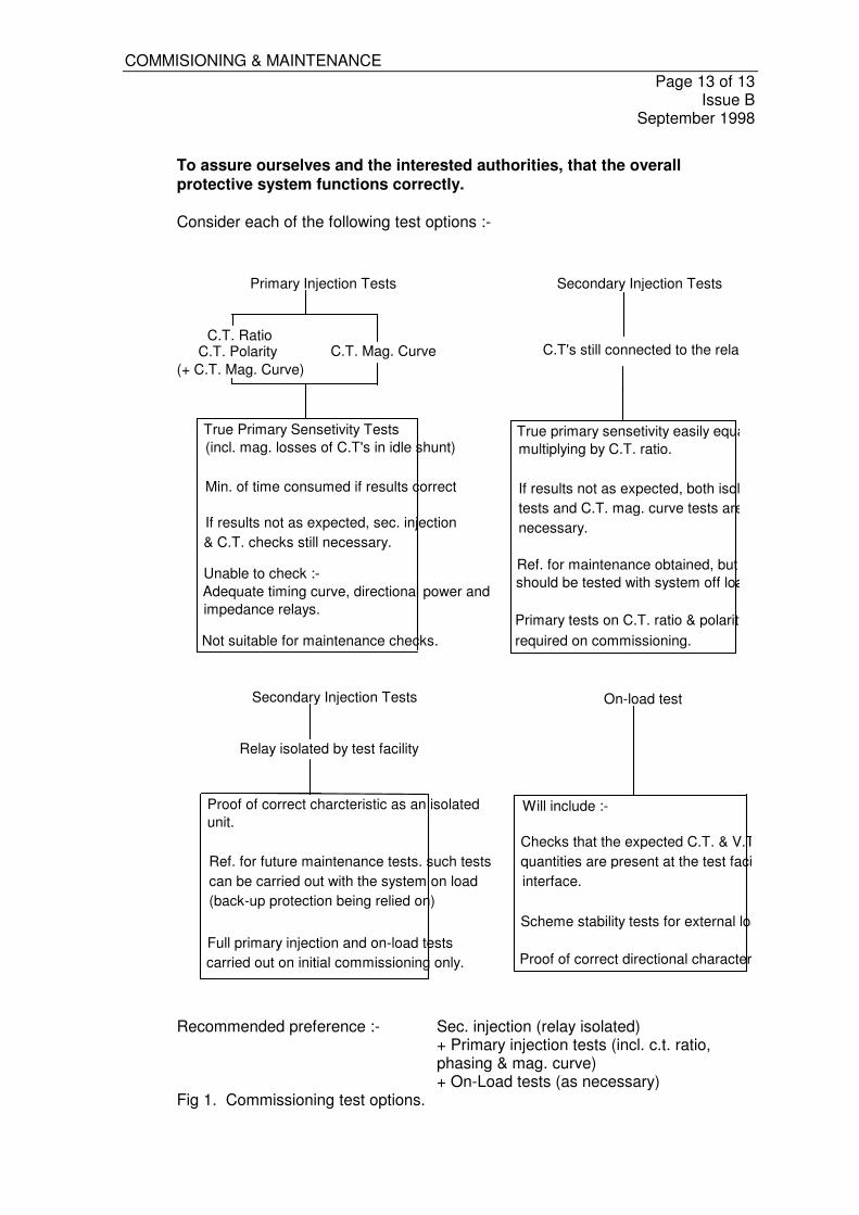
COMMISIONING & MAINTENANCE Page 13 of 13 Issue B September 1998
To assure ourselves and the interested authorities, that the overall protective system functions correctly. Consider each of the following test options :-
Primary Injection Tests
C.T. RatioC.T. Polarity
(+ C.T. Mag. Curve)
True Primary Sensetivity Tests(incl. mag. losses of C.T's in idle shunt)
Min. of time consumed if results correct
If results not as expected, sec. injection& C.T. checks still necessary.
Unable to check :-Adequate timing curve, directional power andimpedance relays.
Not suitable for maintenance checks.
Secondary Injection Tests
C.T's still connected to the relay
True primary sensetivity easily equated bymultiplying by C.T. ratio.
If results not as expected, both isolated relaytests and C.T. mag. curve tests are stillnecessary.
Ref. for maintenance obtained, but relaysshould be tested with system off load.
Primary tests on C.T. ratio & polarity still required on commissioning.
C.T. Mag. Curve
Secondary Injection Tests
Proof of correct charcteristic as an isolatedunit.
Ref. for future maintenance tests. such testscan be carried out with the system on load(back-up protection being relied on)
Full primary injection and on-load testscarried out on initial commissioning only.
On-load test
Will include :-
Checks that the expected C.T. & V.T. quantities are present at the test facilityinterface.
Scheme stability tests for external load / faults
Proof of correct directional characteristics.
Relay isolated by test facility
Recommended preference :- Sec. injection (relay isolated) + Primary injection tests (incl. c.t. ratio, phasing & mag. curve) + On-Load tests (as necessary) Fig 1. Commissioning test options.