24-67 remote base controller version 1idaco.com/manuals/24-67/24-67_manual_101.pdf · the 24-67...
TRANSCRIPT
24-67
Remote Base Controller
Version 1.01
Printings:
Version 1.00: 11/13/2012 Version 1.01: 01/04/2019
TABLE OF CONTENTS
SPECIFICATIONS ........................................................................................................................ 1
1.0 GENERAL DESCRIPTION .................................................................................................... 2 1.1 Description ................................................................................................................. 2 1.2 Capabilities and Features .......................................................................................... 2
2.0 INSTALLATION ..................................................................................................................... 3 2.1 Line Connection ......................................................................................................... 3 2.2 Proper Grounding Practices ....................................................................................... 3 2.3 Switch Settings ........................................................................................................... 3 2.4 Remote Control Applications ...................................................................................... 4
3.0 ADJUSTMENT PROCEDURES .......................................................................................... 10 3.1 Microphone To Line Level ........................................................................................ 10 3.2 Desk Microphone Output Sensitivity ........................................................................ 10 3.3 Internal Microphone Level ........................................................................................ 10 3.4 R28 and R39 - 2175 Hz Notch Filter Adjust ............................................................. 11 3.5 Tone Encode Level .................................................................................................. 11 3.6 MSK Encode Level (MSK Control Option is not available at this time) .................... 11 3.7 DTMF Encode Level (DTMF is not available with product Rev.C and newer units) . 11 3.8 Receive Line Compensation .................................................................................... 11 3.9 Summed Audio Level ............................................................................................... 12 3.10 Speaker Level ......................................................................................................... 12 3.11 Earpiece Level ........................................................................................................ 12 3.12 R29 and R40 - 2175 Hz Notch Filter Adjust ............................................................ 13 3.13 R32 - Guard/Hold Tone Detect ............................................................................... 13
4.0 CIRCUIT DESCRIPTION ..................................................................................................... 14 4.1 Power Supply ........................................................................................................... 14 4.2 Line Interface ........................................................................................................... 14 4.3 Two Wire, No Supervisory, No Alternate Line .......................................................... 14 4.4 Two Wire With Supervisory ...................................................................................... 14 4.5 Two Wire With Alternate Line ................................................................................... 14 4.6 Four Wire, No Supervisory, No Alternate Line ......................................................... 15 4.7 Four Wire With Supervisory ..................................................................................... 15 4.8 Four Wire With Alternate Line .................................................................................. 15 4.9 Two Wire With Alternate Line Summed Audio ......................................................... 16 4.10 Combined Two Wire and Four Wire (for use with 20-88) ........................................ 16 4.11 Receive Audio ......................................................................................................... 16 4.12 Transmit Audio ........................................................................................................ 17 4.13 Digital Control Section ............................................................................................. 18 4.14 MSK Interface (MSK Control Option is not available at this time) ........................... 20 4.15 Parallel Detect ......................................................................................................... 20 4.16 Keypad Board ......................................................................................................... 20 4.17 Clock Option ............................................................................................................ 21 4.18 VU Meter Option ..................................................................................................... 21 4.19 LCD Option ............................................................................................................. 21 4.20 Programming Cable ................................................................................................ 21
4.21 Proper Grounding .................................................................................................... 22
5.0 TROUBLESHOOTING ......................................................................................................... 24 5.1 Microphone Audio Doesn't Reach the Line .............................................................. 24 5.2 VU Meter Doesn't Function ...................................................................................... 24 5.3 Control/Alert Tones Do Not Reach the Line ............................................................. 25 5.4 Control Tones Have No Effect on the Panel ............................................................ 25 5.5 Line Audio Doesn't Reach the Speaker ................................................................... 25 5.6 Earpiece Audio is Not Loud Enough or No Sound ................................................... 26 5.7 A Constant Hum is Present in the Speaker .............................................................. 26 5.8 Background Tone (2175 Hz) Present in Receive Audio ........................................... 26 5.9 Parallel TX Indicator Intermittent or Stuck On .......................................................... 27 5.10 One or More Keys Stuck On or Off ......................................................................... 27 5.11 Faceplate Keys and All LEDs Inoperative ............................................................... 27 5.12 Microprocessor Functioning Improperly .................................................................. 27 5.13 Status Messages ..................................................................................................... 28
PARTS LIST ............................................................................................................................... 30
TEST MODE APPENDIX ............................................................................................................ 38
INSTALLATION DIAGRAMS ..................................................................................................... 49
ADJUSTMENT LOCATOR DIAGRAM ....................................................................................... 51
SCHEMATICS ............................................................................................................................ 52
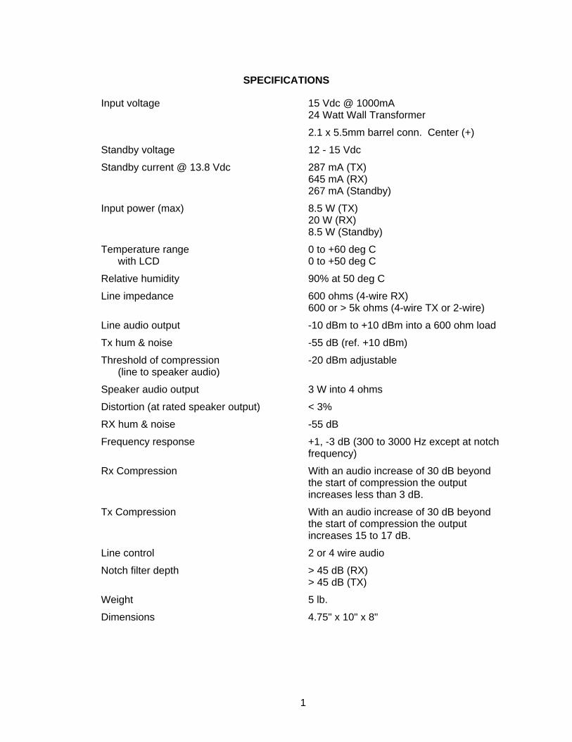
SPECIFICATIONS
Input voltage 15 Vdc @ 1000mA 24 Watt Wall Transformer
2.1 x 5.5mm barrel conn. Center (+)
Standby voltage 12 - 15 Vdc
Standby current @ 13.8 Vdc 287 mA (TX) 645 mA (RX) 267 mA (Standby)
Input power (max) 8.5 W (TX) 20 W (RX) 8.5 W (Standby)
Temperature range with LCD
0 to +60 deg C 0 to +50 deg C
Relative humidity 90% at 50 deg C
Line impedance 600 ohms (4-wire RX) 600 or > 5k ohms (4-wire TX or 2-wire)
Line audio output -10 dBm to +10 dBm into a 600 ohm load
Tx hum & noise -55 dB (ref. +10 dBm)
Threshold of compression (line to speaker audio)
-20 dBm adjustable
Speaker audio output 3 W into 4 ohms
Distortion (at rated speaker output) < 3%
RX hum & noise -55 dB
Frequency response +1, -3 dB (300 to 3000 Hz except at notch frequency)
Rx Compression With an audio increase of 30 dB beyond the start of compression the output increases less than 3 dB.
Tx Compression With an audio increase of 30 dB beyond the start of compression the output increases 15 to 17 dB.
Line control 2 or 4 wire audio
Notch filter depth > 45 dB (RX) > 45 dB (TX)
Weight 5 lb.
Dimensions 4.75" x 10" x 8"
1

1.0 GENERAL DESCRIPTION
1.1 Description
The 24-67 series of remote controllers is used to remotely control repeaters and base station radios. Tone sequences are used by the 24-67 to control the remote repeater or base station radio. The 24-67 requires an appropriate panel in the repeater or at the base station for correct operation. The operating characteristics of the 24-67 can be selected and changed with the programming software which runs on a standard personal computer. The 24-67 is available with either tone signaling or MSK signaling (MSK is not available at this time). The 24-67 Tone remote uses function tones from 550 to 2050 Hz to control the repeater or base station radio while the 24-67 MSK remote uses an MSK modem for control. The 24-67 is available with either a handset or a desk microphone and can operate with either a 2-wire or a 4-wire line. The 24-67 provides parallel detect as well as alternate line and supervisory modes of operation. The 24-67 is available with clock and VU meter display and can be set on a desk or wall mounted. A 12 V power cable is also available which allows the 24-67 to be operated from a 12 Vdc source.
1.2 Capabilities and Features
♦ Tone or MSK signaling (MSK is not available at this time) ♦ 2 wire or 4 wire operation
♦ Handset or desk microphone
♦ Desk or wall mount
♦ PC programmable
♦ Non-volatile memory
♦ 8 or 99 channels for 24-67 Tone remote
♦ 99 channels or up to 32 systems for 24-67 MSK remote
♦ Operation from 12 Vdc source
♦ Parallel remote update
♦ Full duplex operation
♦ Intercom
♦ Alert tone
♦ Supervisory option
♦ Alternate line with or without summed audio option
♦ Clock option
♦ VU meter option
♦ LCD option
2

2.0 INSTALLATION
2.1 Line Connection
The 24-67 allows either 2-wire or 4-wire lines to be used. The choice of which one of these to use should be based upon cost, availability, performance, and the conditions that the 24-67 is to operate within. Two wire lines have one voice grade pair that is used for both the transmit and receive audio. They are simple to install and, depending upon local service, may be more economical. Four wire lines provide two voice grade pairs, one for transmit audio and the other for receive audio. This provides full duplex operation allowing the 24-67 to transmit and receive at the same time. Cost may be a factor since two voice grade pairs are required. Four wire lines would be used with customer owned multiplex microwave systems and with leased lines that do not use hybrids in the transmission paths. The line connectors are found on the back of the 24-67. Connector J5 is the primary connector and is marked with one notch in the plastic case. Connector J6 is the secondary connector and is marked with two notches in the plastic case. The line should be a standard 2 or 4 wire cable that is available anywhere that telephone accessories are sold. With more than one remote in the system and no alternate line or supervisory option installed, J5 is used for the line from the base station and J6 is used to connect the line to additional remotes. With the supervisory option installed, J6 is used for the line from the base station and J5 connects to the remotes under supervisory control. If the 24-67 has the alternate line option installed, J5 is used for the primary line and J6 is used for the alternate line. Section 2.6 Remote Control Applications describes the 24-67 setup and line connections for numerous different remote control applications. Refer also to the 24-67 installation diagrams in the back of this manual.
2.2 Proper Grounding Practices
The surge protection diodes on the two wire audio lines, and the four wire audio lines protect the 24-67 from line transients. It is imperative that a good earth ground be used on the ground conductor screw terminal (J1) or a SERIOUS SHOCK HAZARD could develop if lightning were to strike the power line or the audio lines. In order to protect the operator to the highest possible degree, obtain a good earth ground for the ground conductor on the ground conductor screw terminal. The surge protection diodes are of little value without this earth ground and EXTREME CAUTION must be observed when servicing the 24-67 in the presence of a local lightning storm. In addition, the internal circuits can be damaged when a good earth ground is not used and lightning strikes the power line or the audio lines.
2.3 Switch Settings
This section describes the function of the individual switches SW1, SW2 and SW3. SW1: The 24-67 firmware upgrade process shall be initiated by pressing PCB switch
SW1 during startup.
3
2.3 Switch Settings (cont.)
SW2: The 24-67 Test mode shall be entered by depressing PCB switch SW2. Test mode can also be entered by pressing the keypad button 1 and keypad button 3 during startup.
SW3: The 24-67 Microcontroller can be reset to startup by depressing PCB switch SW3.
2.4 Remote Control Applications
There are numerous remote control applications that can be provided by the 24-67. Each application requires a specific jumper configuration and specific line connections. Certain 24-67 options are also required for each application. The following is a description of each of the remote control applications.
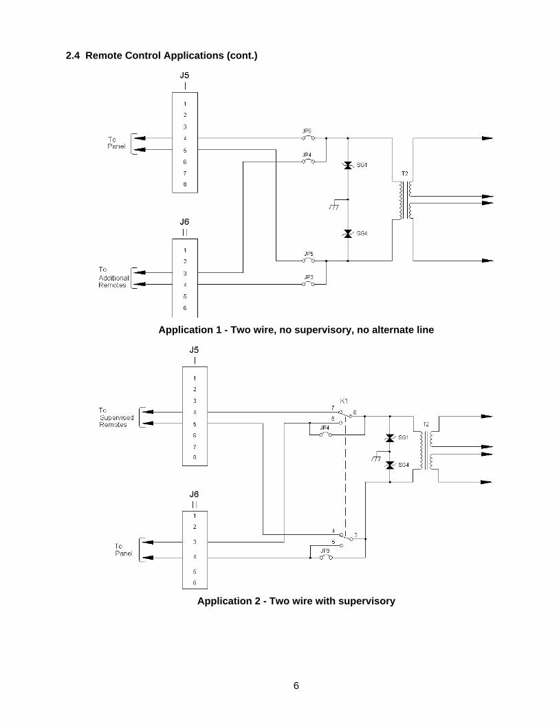
Application 1 - Two wire, no supervisory, no alternate line: This application provides basic 2-wire operation. The base station is connected to J5 and additional parallel remotes are connected to J6.
Application 2 - Two wire with supervisory: This application provides 2-wire operation with supervisory control. The base station is connected to J6 and the parallel remotes under supervisory control are connected to J5.
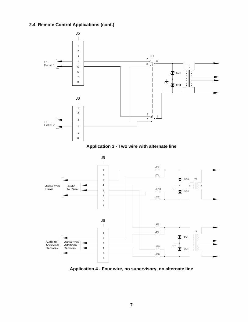
Application 3 - Two wire with alternate line: This application provides 2-wire operation with alternate line selection. The primary line is connected to J5 and the alternate line is connected to J6.
Application 4 - Four wire, no supervisory, no alternate line: This application provides basic 4-wire operation. The base station is connected to J5 and additional parallel remotes are connected to J6.
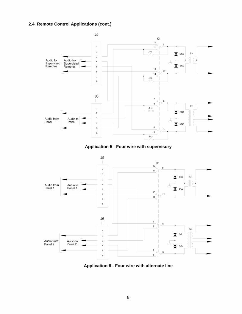
Application 5 - Four wire with supervisory: This application provides 4-wire operation with supervisory control. The base station is connected to J6 and the parallel remotes under supervisory control are connected to J5.
Application 6 - Four wire with alternate line: This application provides 4-wire operation with alternate line selection. The primary line is connected to J5 and the alternate line is connected to J6.
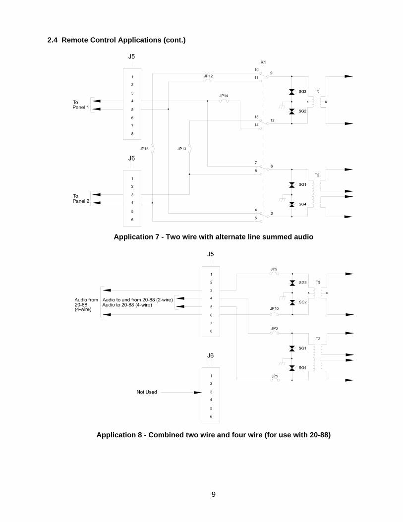
Application 7 - Two wire with alternate line summed audio: This application provides 2-wire operation with alternate line selection. Audio from the alternate line is also summed with audio from the primary line. The primary line is connected to J5 and the alternate line is connected to J6.
Application 8 - Combined two wire and four wire (for use with 20-88): This application allows operation with an IDA 20-88 that is interfaced to both 2-wire and 4-wire lines. The selected line from the 20-88 is connected to J5. J6 is not used.
4
2.4 Remote Control Applications (cont.)
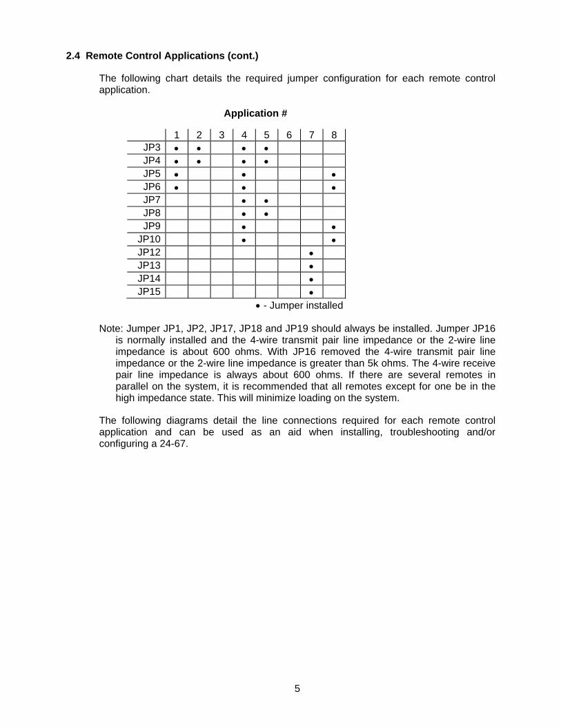
The following chart details the required jumper configuration for each remote control application.
Application #
1 2 3 4 5 6 7 8 JP3 • • • • JP4 • • • • JP5 • • • JP6 • • • JP7 • • JP8 • • JP9 • •
JP10 • • JP12 • JP13 • JP14 • JP15 •
• - Jumper installed Note: Jumper JP1, JP2, JP17, JP18 and JP19 should always be installed. Jumper JP16
is normally installed and the 4-wire transmit pair line impedance or the 2-wire line impedance is about 600 ohms. With JP16 removed the 4-wire transmit pair line impedance or the 2-wire line impedance is greater than 5k ohms. The 4-wire receive pair line impedance is always about 600 ohms. If there are several remotes in parallel on the system, it is recommended that all remotes except for one be in the high impedance state. This will minimize loading on the system.
The following diagrams detail the line connections required for each remote control application and can be used as an aid when installing, troubleshooting and/or configuring a 24-67.
5
2.4 Remote Control Applications (cont.)
Application 1 - Two wire, no supervisory, no alternate line
Application 2 - Two wire with supervisory
6
2.4 Remote Control Applications (cont.)
Application 3 - Two wire with alternate line
Application 4 - Four wire, no supervisory, no alternate line
7
2.4 Remote Control Applications (cont.)
Application 5 - Four wire with supervisory
Application 6 - Four wire with alternate line
8
2.4 Remote Control Applications (cont.)
Application 7 - Two wire with alternate line summed audio
Application 8 - Combined two wire and four wire (for use with 20-88)
9
3.0 ADJUSTMENT PROCEDURES
The following will explain the adjustment procedure for all potentiometers and EPOTs in the 24-67. Most potentiometers and EPOTs are factory preset and will, in most cases, not need adjustment. The factory adjustment procedure and the recommended field adjustment procedure are given for most potentiometers and EPOTs. Refer to the programming and adjustment utility software application or Test mode for the complete adjustment procedure. If your 24-67 has a LCD option you can also set these adjustments from the Test mode. Test mode shall be entered by depressing PCB switch SW2. Test mode can also be entered by pressing the keypad button 1 and keypad button 3 during startup. Refer to the Test mode appendix at the back of this manual for more information.
3.1 Microphone To Line Level
Factory adjustment procedure - With the handset or desk microphone removed, inject a 1 kHz tone at 1 Vrms from a 600 ohm generator into the microphone input J11-4. Place the 24-67 into intercom mode and begin transmitting by grounding J11-3. Connect a 600 ohm load to the output terminals J5-4 and J5-5. Adjust EPOT via programming and adjustment utility software application or Test mode so that 0 dBm (.77 Vrms) appears across the 600 ohm load. Field adjustment procedure - While speaking into the handset or desk microphone, monitor the output of the base station or repeater transmitter with a service monitor or deviation meter and Adjust EPOT via programming and adjustment utility software application or Test mode for proper transmitter deviation.
3.2 Desk Microphone Output Sensitivity
The audio output level of the desk microphone can be adjusted through a hole in the bottom of the desk microphone. A small jeweler's flat blade screwdriver will be needed. The adjustment may need to be made depending upon background noise in the environment where the 24-67 is located and also upon the user of the desk microphone and how close and/or loud the user speaks.
3.3 Internal Microphone Level
Factory adjustment procedure - Microphone To Line Level EPOT should be set properly before making this adjustment. Inject a 1 kHz tone at 1 Vrms from a 600 ohm generator into the internal microphone input MK1 pin 1+ (right side of R156). Connect a 600 ohm load across the output terminals J5-4 and J5-5 and begin transmitting by holding down the internal microphone PTT button. Adjust EPOT via programming and adjustment utility software application or Test mode so that 0 dBm (0.77 Vrms) appears across the 600 ohm load. Field adjustment procedure - The internal microphone level can be adjusted by speaking into the microphone, monitoring the output, and adjusting EPOT via programming and adjustment utility software application or Test mode to the desired level.
10

3.4 R28 and R39 - 2175 Hz Notch Filter Adjust
With the handset or desk microphone removed, inject a 2175 Hz tone at 1 Vrms into the microphone input J11-4. Begin transmitting by grounding J11-3 and adjust R28 and R39 for a minimum reading across the output terminals J5-4 and J5-5. Going back and forth between the two potentiometers will result in the best adjustment.
3.5 Tone Encode Level
Factory adjustment procedure - Remove the handset or desk microphone and begin transmitting by grounding J11-3. Install a 600 ohm load across the output terminals J5-4 and J5-5 and measure the AC voltage across it. The 24-67 will be generating a 2175 Hz hold tone across the load. Adjust EPOT via programming and adjustment utility software application or Test mode so that -20 dBm (.08 Vrms) is across the load. Field adjustment procedure - Turn EPOT via programming and adjustment utility software application down so that the 24-67 will not key the base station or repeater panel. While keying the 24-67 several times, Adjust EPOT via programming and adjustment utility software application or Test mode until it keys the base station or repeater panel reliably.
3.6 MSK Encode Level (MSK Control Option is not available at this time)
Factory adjustment procedure - Put the 24-67 MSK remote into test mode and press any button until the MSK test tone is being sent to the line. Install a 600 ohm load across the line and Adjust EPOT via programming and adjustment utility software application or Test mode for 0 dBm (.77 Vrms) across the load. Field adjustment procedure - If the panel does not decode updates sent by the 24-67 MSK remote, Adjust EPOT via programming and adjustment utility software application or Test mode until the panel decodes the updates reliably.
3.7 DTMF Encode Level (DTMF is not available with product Rev.C and newer units)
Factory adjustment procedure - Place the 24-67 into intercom mode. Connect a 600 ohm load to the output terminals J5-4 and J5-5. Adjust EPOT via programming and adjustment utility software application or Test mode so that 0 dBm (.77 Vrms) appears across the 600 ohm load. Field adjustment procedure - While generating a DTMF tone from the keypad, monitor the output of the base station or repeater transmitter with a service monitor or deviation meter and Adjust EPOT via programming and adjustment utility software application or Test mode for proper transmitter deviation.
3.8 Receive Line Compensation
Factory adjustment procedure - For 2-wire or 4-wire applications, these EPOT adjustments are set to default values.
11
3.8 Receive Line Compensation (cont.)
Field adjustment procedure - These EPOT adjustments can be made via programming and adjustment utility software application or Test mode. This adjustment should normally not need to be adjusted in the field. However, if levels coming into the 24-67 are greater than +10 dBm (2.45 Vrms) or there is excessive line noise, this EPOT should be turned down.
3.9 Summed Audio Level
Factory adjustment procedure - Input a 1.5 kHz tone at 1 Vrms across J5-4 and J5-5 and input a 800 Hz tone at 1 Vrms across J6-3 and J6-4. Measure the output at TP1 and Adjust EPOT via programming and adjustment utility software application or Test mode so that the 800 Hz (alternate) signal is below the 1.5 kHz (primary) signal. When the alternate line button is depressed, the primary signal becomes the 800 Hz signal and the alternate signal becomes the 1.5 kHz signal. However, the alternate signal should remain below the primary signal. Field adjustment procedure - When using the summed audio option, it may be necessary to adjust the alternate line audio. This can be done by adjusting EPOT via programming and adjustment utility software application or Test mode to the desired level.
3.10 Speaker Level
Factory adjustment procedure - Receive Line Compensation 2-wire and 4-wire EPOT’s must be set properly before making this adjustment. With the volume control potentiometer R1 at maximum, Adjust EPOT via programming and adjustment utility software application or Test mode so that 3.45 Vrms appears across the speaker terminals while receiving a 1 kHz tone at +10 dBm (2.45 Vrms). Field Adjustment procedure - While connected to the system and receiving audio from the highest level source, Adjust EPOT via programming and adjustment utility software application or Test mode so that audio in the speaker is a comfortable listening level. Do not turn it up too high since this will cause distortion and clipping. The audio should not exceed 3.45 Vrms at the speaker terminals.
3.11 Earpiece Level
Factory adjustment procedure - Receive Line Compensation 2-wire and 4-wire EPOT’s must be set properly before making this adjustment. With a handset or a 150 ohm load connected from J11-2 to ground, Adjust EPOT via programming and adjustment utility software application or Test mode for 150 mV across the load while receiving a 1 kHz tone at +10 dBm (2.45 Vrms). The volume control potentiometer R1 should be set to maximum. Field adjustment procedure - The earpiece and the base speaker are both controlled by the volume control potentiometer R1. It may be necessary in certain noisy environments to increase the level to the earpiece. While in the noisy environment and receiving audio from the source with the least level coming in, Adjust EPOT via programming and
12
3.11 Earpiece Level (cont.)
adjustment utility software application or Test mode for a comfortable listening level with the volume control potentiometer at maximum.
3.12 R29 and R40 - 2175 Hz Notch Filter Adjust
Factory adjustment procedure - Apply a 2175 Hz tone at +10 dBm (2.45 Vrms) across J5-4 and J5-5. Adjust R29 and R40 for a minimum reading across the speaker. Going back and forth between the two potentiometers will result in the best adjustment. Field adjustment procedure - While receiving a 2175 Hz hold tone from a paralleled remote, adjust R29 and R40 until little or no hold tone is heard in the speaker. Going back and forth between the two potentiometers will result in the best adjustment.
3.13 R32 - Guard/Hold Tone Detect
Factory adjustment procedure - Apply a 2175 Hz tone at +10 dBm (2.45 Vrms) across J5-4 and J5-5. Adjust Detection Gain EPOT via programming and adjustment utility software application or Test mode half ways from the bottom setting. Adjust R32 for a maximum level at TP2 and then adjust Detection Gain EPOT via programming and adjustment utility software application or Test mode for 2.5 Vrms at TP2. Reduce input level by 20 dB (to 0.24 Vrms) and check that the DC level at U11A pin1 has changed from 0 Vdc to 3.3 Vdc. Reduce input level by a total of 50 dB (to .008 Vrms) and check that the DC level at U11B pin 7 has changed from 0 Vdc to 3.3 Vdc. Field adjustment procedure - Adjust R32 as described in the factory adjustment procedure. Adjust Detection Gain EPOT via programming and adjustment utility software application or Test mode to the bottom setting. While a paralleled remote is being keyed several times, adjust Detection Gain EPOT via programming and adjustment utility software application or Test mode up until the TX indicator comes on and follows the paralleled remote. It is best to use the paralleled remote that is the furthest away from the unit being setup or, in other words, the paralleled remote that has the most line loss. Check to be sure that all other paralleled remotes will make the TX indicator illuminate.
13
4.0 CIRCUIT DESCRIPTION
4.1 Power Supply
Power is supplied to the 24-67 via the supplied 15VDC wall transformer. It is connected at J7 on the back of the 24-67. The polarity of the connector must be correct. From J7 the power is routed through a diode D11 and a 1 amp fuse F1. Diode D11 prevents a reverse polarity from harming the 24-67. Power is fed into voltage regulator U20. The output voltage of U20 is set to 12.5. This 12.5 Vdc through a diode D16 drives the audio section of the 24-67. It is also fed into voltage regulator U26, U27 and U38. The output voltage of U27 is set to 3.3 Vdc. The output voltage of U38 is set to 5 Vdc. The output voltage of U26 is set to 10 Vdc. It is also fed into voltage regulator U36. The output voltage of U36 is set to 5 Vdc REF. The 3.3 Vdc powers the digital section of the 24-67. The 24-67 can be operated from a 13.8 Vdc supply through connector J2. Diode D17 prevents a reverse polarity from harming the 24-67.
4.2 Line Interface
The line is connected to the 24-67 through the two back panel modular jacks, J5 and J6. The 24-67 can be configured in several different configurations. It can be 2-wire or 4-wire, 2-wire or 4-wire with supervisory control, and 2-wire or 4-wire with alternate line. The lines are protected from transients by surge arresters SG1 - SG4.
4.3 Two Wire, No Supervisory, No Alternate Line
In the basic two wire configuration, the 2-wire line from the base station is connected to J5-4 and J5-5. Jumpers JP5 and JP6 are installed so that audio to and from the base station is routed through transformer T2. With jumpers JP3 and JP4 installed, additional remotes may be connected in parallel to J6-3 and J6-4. Receive audio is coupled through transformer T2 and passes from pin 4 of T2 through EPOT U8C to the buffer amplifier U10D. Transmit audio coming from pin 1 of U14 goes to pin 6 T2 and pin 1 of U21 goes to pin 7 T2 where it is coupled to the line.
4.4 Two Wire With Supervisory
In the two wire configuration with supervisory control, relay K1 is used for implementation of the supervisory mode. Only one user should have supervisor privileges. The 2-wire line from the base station is connected to J6-3 and J6-4. Additional remotes should be connected to J5-4 and J5-5. Jumpers JP3 and JP4 are installed so that audio to and from the base station is always routed through transformer T2. When the SUPER key is pressed, K1 is activated thus disconnecting any remotes connected to J5 from the line. Receive audio is coupled through transformer T2 and passes from pin 4 of T2 through EPOT U8C to the buffer amplifier U10D. Transmit audio coming from pin 1 of U14 goes to pin 6 T2 and pin 1 of U21 goes to pin 7 T2 where it is coupled to the line.
4.5 Two Wire With Alternate Line
In the two wire configuration with alternate line, relay K1 is used to select the alternate line. The 2-wire line from the primary base station is connected to J5-4 and J5-5. The 2-
14

4.5 Two Wire With Alternate Line (cont.)
wire line from the alternate base station is connected to J6-3 and J6-4. When the ALT key is pressed, K1 is activated thereby connecting the alternate line to transformer T2. Receive audio is coupled through transformer T2 and passes from pin 4 of T2 through EPOT U8C to the buffer amplifier U10D. Transmit audio coming from pin 1 of U14 goes to pin 6 T2 and pin 1 of U21 goes to pin 7 T2 where it is coupled to the line.
4.6 Four Wire, No Supervisory, No Alternate Line
In the basic four wire configuration, the 4-wire line from the base station is connected to J5. Audio from the base station comes in on J5-3 and J5-6 and is passed through jumpers JP9 and JP10 to transformer T3. The audio is coupled through transformer T3 and passes from pin 6 of T3 through EPOT U8B to the buffer amplifier U10D. Transmit audio coming from pin 1 of U14 goes to pin 6 T2 and pin 1 of U21 goes to pin 7 of transformer T2. The audio is coupled through transformer T2 and passes through jumpers JP5 and JP6. The audio is then passed to the base station through J5-4 and J5-5. Additional remotes may be connected in parallel to J6. Jumpers JP7 and JP8 pass audio from the base station to the parallel remotes through J6-2 and J6-5. Jumpers JP3 and JP4 pass audio from the parallel remotes to the base station through J6-3 and J6-4.
4.7 Four Wire With Supervisory
In the four wire configuration with supervisory control, relay K1 is used for implementation of the supervisory mode. Only one user should have supervisor privileges. The 4-wire line from the base station is connected to J6 with J6-2 and J6-5 used for audio from the base station and J6-3 and J6-4 used for audio to the base station. Additional remotes should be connected in parallel to J5 with J5-3 and J5-6 used for audio from the base station to the parallel remotes and J5-4 and J5-5 used for audio from the parallel remotes to the base station. When the SUPER key is pressed, K1 is activated thus disconnecting any remotes connected to J5 from the line. Jumpers JP7 and JP8 allow audio from the base station to always be coupled through transformer T3 and where it then passes from pin 6 of T3 through EPOT U8B to the buffer amplifier U10D. Transmit audio coming from pin 1 of U14 goes to pin 6 T2 and pin 1 of U21 goes to pin 7 of transformer T2. Jumpers JP3 and JP4 are installed so that audio coupled through transformer T2 is always passed to the base station.
4.8 Four Wire With Alternate Line
In the four wire configuration with alternate line, relay K1 is used to select the alternate line. The 4-wire line from the primary base station is connected to J5 with J5-3 and J5-6 used for audio from the base station and J5-4 and J5-5 used for audio to the base station. The 4-wire line from the alternate base station is connected to J6 with J6-2 and J6-5 used for audio from the base station and J6-3 and J6-4 used for audio to the base station. When the ALT key is pressed, K1 is activated thereby connecting the alternate line to transformers T2 and T3. Audio from the base station is coupled through transformer T3 and passes from pin 6 of T3 through EPOT U8B to the buffer amplifier U10D. Transmit audio coming from pin 1 of U14 goes to pin 6 T2 and pin 1 of U21 goes
15
4.8 Four Wire With Alternate Line (cont.)
to pin 7 of transformer T2. The audio is coupled through transformer T2 and is then passed to the base station.
4.9 Two Wire With Alternate Line Summed Audio
In the two wire configuration with alternate line and summed audio, relay K1 is used to select the alternate line. The 2-wire line from the primary base station is connected to J5-4 and J5-5. The 2-wire line from the alternate base station is connected to J6-3 and J6-4. When the alternate line is not selected, the primary line is connected to transformer T2 and the alternate line is connected to transformer T3 through jumpers JP13 and JP15. When the ALT key is pressed, K1 is activated thereby selecting the alternate line and connecting it to transformer T2. The primary line is then connected to transformer T3 through jumpers JP12 and JP14. Receive audio from the selected line is coupled through transformer T2 and passes from pin 4 of T2 through EPOT U8C to the buffer amplifier U10D where it is summed with audio coupled through transformer T3 and passes from pin 6 of T3 through EPOT U8B from the unselected line. EPOT U8B is used to control the level of audio received from the unselected line. Transmit audio coming from pin 1 of U14 goes to pin 6 T2 and pin 1 of U21 goes to pin 7 of transformer T2 where it is coupled to the selected line.
4.10 Combined Two Wire and Four Wire (for use with 20-88)
The 24-67 can be used with an IDA 20-88 to allow the 24-67 to control multiple base stations. The lines from the base stations are connected to the 20-88 which selects one of the lines and passes that line to the 24-67. This configuration allows both 2-wire and 4-wire lines to be connected to the 20-88 at the same time. The selected line from the 20-88 is connected to J5. J6 is not used. Jumpers JP5 and JP6 connect J5-4 and J5-5 to transformer T2 which couples transmit audio coming from pin 1 of U14 goes to pin 6 T2 and pin 1 of U21 goes to pin 7 T2 where it is coupled to the line for both 2-wire and 4-wire lines. Receive audio is also coupled through transformer T2 for 2-wire lines and passed to the buffer amplifier U10D. Jumpers JP9 and JP10 connect J5-3 and J5-6 to transformer T3. Receive audio from 4-wire lines is coupled through transformer T3 and passed to the buffer amplifier U10D. EPOT U8B is used to control the level of audio received from 4-wire lines and should be adjusted so that audio received from the 4-wire lines is at the same level as audio received from the 2-wire lines.
4.11 Receive Audio
Receive audio from the summing amplifier U10D in the line interface section is passed to the receive audio buffer amplifier U5A. The audio then goes to an automatic gain control (AGC) circuit. The AGC circuit provides for a constant output voltage over an input range of 30 dB. The AGC circuit is comprised of U15B and U5D and their associated components. The AGC output is at pin 14 of U5D. The audio input on pin 13 of U15B is rectified internally and is used to control the gain of the internal gain cell that is connected between pin 11 and pin 9 of U15B. The attack time of the AGC is determined by C156 and the recovery time is determined by C62. From pin 14 of U5D the audio signal goes to pin 14 of audio gate U16B. This gate is normally enabled unless the AGC bypass has been enabled. If the AGC bypass circuit
16
4.11 Receive Audio (cont.)
has been enabled, this gate will be disabled and audio will be routed to the notch filter from pin 3 of audio gate U16A instead of pin 15 of audio gate U16B. The notch filter is comprised of U5B and U5C and their associated components. Potentiometers R29 and R40 are used to tune the notch filter to 2175 Hz. The notch filter removes the 2175 Hz hold tone from the line audio to prevent it from being heard. From the notch filter circuit pin 8 of U5C, the audio goes to the summing amplifier U4B. The line audio from the summing amplifier U4B is amplified by U1C and then passed to the volume control potentiometer R1. D1 and D2 are used to help protect the 24-67 from electrostatic discharges. Resistor R3 prevents the audio from being turned completely off. From the volume control potentiometer, the audio goes to the headset earpiece level adjustment EPOT U8D and the handset earpiece level adjustment EPOT U13D. The audio is then fed from EPOT U8D to the headset earpiece driver U4A, also from EPOT U13D to the handset earpiece driver U6B. The output of U6B is passed to the earpiece enable gate U16D. If the 24-67 is equipped with a handset, this gate allows the audio to go to the earpiece in the handset. If the 24-67 is equipped with a desk microphone, the earpiece enable gate will be disabled. This allows pin 2 on J11 to be used as the monitor line from the desk microphone From the volume control potentiometer, the audio also passes to the speaker level adjustment EPOT U8A then to the speaker driver preamp circuit. The preamp circuit is comprised of U1A and U1B and their associated components. The preamp output is at pin 1 of U1A and pin 7 of U1B. The audio is then fed into the speaker driver U3. U3 and its associated circuitry is stereo audio power amplifier that contains two identical amplifiers capable of delivering 6 Watts per channel of continuous average power into a 4 ohm load. The gain of each channel is fixed at 20 dB. The A output, U3 pins 7 and 8 of the speaker driver goes to J8, the internal speaker connector. The B output, U3 pins 13 and 14 of the speaker driver goes to J18, the external speaker connector.
4.12 Transmit Audio
Microphone audio from the handset or the desk microphone comes from pin 4 of J11. The microphone is biased by resistors R11 and R22. The microphone audio then passes through an electrostatic discharge protection circuit consisting of D3 and D4. The audio is then compressed by the compression circuit consisting of U15A and U6C and their associated components. The compression circuit output is at pin 8 of U6C. The audio signal fed back from pin 8 of U6C to pin 3 of U15A is rectified internally and controls the gain of the internal gain cell that is connected between pin 5 and pin 7 of U15A. The attack time is determined by C150 and the recovery time is determined by C58. From pin 8 of U6C the signal goes to the 2175 Hz notch filter consisting of U10B and U10C and their associated components. Potentiometers R28 and R39 are used to tune the notch filter to 2175 Hz. This filter notches out any 2175 Hz component that is present in the microphone audio. The notch depth is greater than 45 dB. This helps prevent a user's voice from falsing any 2175 Hz detectors that are in a panel or another parallel remote.
17

4.12 Transmit Audio (cont.)
The microphone audio then passes through the microphone EPOT U9C. This EPOT allows muting of the microphone audio when necessary to eliminate any audio feedback ringing. This EPOT U9C is also the transmit audio adjustment potentiometer. U10A is a summing amplifier that sums the transmit audio, the function tones and the DTMF tones. The function tones are generated by the Audio Signaling Processor U19 and its associated components. EPOT U9B is used to adjust the level of the function tones. The DTMF tones are generated by the DTMF Transceiver U24 and its associated components. EPOT U9D is used to adjust the level of the DTMF tones. The output of U10A goes to the line driver U14 and U21 which drives the line coupling transformer T2. Jumper JP16 is used to change the 4-wire transmit pair line impedance or the 2-wire line impedance from about 600 ohms when JP16 is on to greater than 5k ohms when JP16 is off.
4.13 Digital Control Section
The 24-67 is controlled by U41 which is a 16-bit Microcontroller. This microcontroller incorporates serial communication UART and I²C. This microcontroller also incorporates general purpose I/O ports and a parallel data communication port. The control program for U41 is stored in the internal 128KB Flash memory. Other inputs to U41 are the monitor line from a desk microphone, external PTT from the foot switch connector, local PTT from the handset or desk microphone and encode PTT from the internal encode/decode connector. Outputs from U41 are four I/O lines that go to the keypad board interface controller U39 to allow U41 to control the display LEDs and the LCD. Other outputs from U41 are the DTMF, MSK, and Tone internal speaker enable which enables audio from these sources to the internal speaker. U42 is a CPU low voltage reset IC that functions as a manual reset and low voltage reset for U41. This causes pin 1 of U42 to stay low. Pin 1 of U42 is also low whenever the 3.3 Vdc power supply is below 2.7 Vdc. This ensures that U41 is properly reset on power-up. All of the programmable operating characteristics of the 24-67 are stored in U40 which is a serial EEPROM. The data on pin 5 of U40 is read from or written into U18 by the clock signal on pin 6 of U40. The data in U40 is checked on power-up to determine if it has been corrupted. If the data in U40 has been corrupted, an error indication will be given on the front panel display. The data stored in U40 is changed by using the programming cable and the programming software supplied by IDA.
18

4.13 Digital Control Section (cont.)
U31 is an 8-bit output latch that is used to control various audio gates and one relay. Three of the outputs are connected to open collector transistors Q1, Q4 and Q5. These three outputs are used to mute the speaker audio, enable the line driver and control the supervisory/alternate line relay K1. Another two of the outputs are connected to audio gates in U7. These two outputs are used to enable encode audio from the internal encode/decode connector J13 and microphone audio from the headset connector J14. U18 is an 8-bit microcontroller. Data written to it by U41 controls the Signaling Processor U19. U19 is used to generate the tones required by the 24-67 including the guard tone, hold tone, function tones, alert tone and various other tones. U19 also decodes function tone sequences from the line and reports them to U18. J10 is the connection to the keypad board. There are two power pins, 5 Vdc and 13.8 Vdc, and a ground pin. There are four row outputs to the keypad matrix and three column inputs from the keypad matrix. There are the four I/O lines for controlling the display LEDs and the LCD. There is also the analog VU signal for the VU meter on the display.
19
4.14 MSK Interface (MSK Control Option is not available at this time)
U25 is an MSK modem and is used to encode and decode the MSK data. Crystal Y3 provides a 4 MHz clock to U25. The output of the AGC circuit is fed to pin 3 of U25 which will decode MSK data from this audio. The decoded data is then read from U25 by the microprocessor. Data to be transmitted is written to U25 by the microprocessor. U25 converts this data to MSK tones which then appear on pin 2 of U25. The MSK tones pass through to the summing amplifier U10A. EPOT U9A is used to adjust the level to control the gain of the MSK tones through the summing amplifier. The MSK tones are then passed to the line driver and on to the line.
4.15 Parallel Detect
Line audio enters the parallel detect circuit through pin 1 of U5 and is passed into the 2175 Hz bandpass filter through EPOT U13A. EPOT U13A adjusts the level of audio into the bandpass filter and therefore into the guard and hold tone detect circuits. The bandpass filter is comprised of U12A, U12B, and U12C and their associated components. Potentiometer R32 is used to tune the bandpass filter to 2175 Hz. The 2175 Hz tones that come out of the bandpass filter are passed into the guard and hold tone detect circuits. For the guard tone detect circuit, audio passes through C171 to diodes D9. These diodes pass only the positive transitions of the 2175 Hz tones to capacitor C63 which causes C63 to charge up. During negative transitions, C63 is discharged through resistor R114. Pin 1 of U11A will be turned on when the charge on C63 is greater than the voltage on pin 2 of U11A. When pin 1 of U11A is on, pin 1 will be pulled high which indicates that guard tone is being detected. For the hold tone detect circuit, audio is passed to amplifier U12D which provides approximately 30 dB of gain. Diodes D10 pass only the positive transitions of the 2175 Hz tones to capacitor C172 which causes C1 to charge up. During negative transitions, C1 is discharged through resistor R115. Pin 7 of U11B will be turned on when the charge on C172 is greater than the voltage on pin 6 of U11B. When pin 7 of U11A is on, pin 7 will be pulled high which indicates that hold tone is being detected.
4.16 Keypad Board
The keypad board is mounted on the faceplate of the 24-67. It is connected to J10 on the base board by a ribbon cable that is soldered to J5 on the keypad board. The keypad board has the contacts for the front panel buttons etched on it, and provides a backplane for the front panel buttons. The rows and columns of the keypad are fed to the baseboard through connector J5. The microprocessor determines if a certain key is pressed by pulling the row input for that key low and then checking to see if the column output for that key also goes low. LEDs are provided for each button and also for the TX indicator. These LEDs are driven by the LED display driver U1 which also drives the single digit 7-segment LED display D1 when D1 is installed. This driver has a serial interface to the microprocessor on the base board. Serial data coming from the baseboard on pin 1 is clocked into U1 by the clock signal on pin 13. When all the data is clocked in, pin 12 is pulsed to load the data into the drivers.
20

4.16 Keypad Board (cont.)
Also located on the keypad board are the mounting sockets for the clock, VU meter, and LCD options. The clock option plugs into J4 and the LCD option plugs into J3. The VU meter option plugs into either J1 or J2 depending on if the LCD option is installed.
4.17 Clock Option
The clock option plugs into J4 on the keypad board. It consists of a four digit 7-segment LED clock display module that is connected through J4 to the LED display driver U1 on the keypad board. This option is used to display the time of day and in some configurations is also used to display the frequency, channel, or system and group selected.
4.18 VU Meter Option
The VU meter option plugs into J1 on the keypad board when the LCD option is installed and into J2 when the LCD option is not installed. This option converts a DC signal level on pin 6 of J1 or J2 to a readout on an LED bar graph. This DC signal comes from the base board through the keypad board. On the base board the transmit signal is fed to an amplifier consisting of U11A and its associated components. The output of the amplifier is then fed to a rectifier circuit consisting of C66, D11, D12, and C67. The resulting DC signal is then passed through a resistor divider network of R83 and R84 before being sent to the keypad board and the VU meter option board.
4.19 LCD Option
The LCD option includes a 32 character (two line) LCD module which plugs into J3 on the keypad board. Serial data from the microprocessor is transmitted to U2 on the keypad board which is an 8-bit serial input, parallel output latch. Serial data coming in on pin 14 is clocked into U2 by the clock signal on pin 11. Once all 8 bits have been clocked in, data is transferred to the LCD (pins 7 - 14 of J3) by a rising edge on pin 12 of U2. The contrast level of the LCD is adjusted using potentiometer R8 on the keypad board.
4.20 Programming Cable
The programming cable is used for programming the desired configuration into the 24-67. One end of the cable is an eight position modular connector that plugs into J5 on the 24-67. The other end is a DB-25 connector that connects to the serial port of the computer. Inside the housing of the DB-25 connector is a TTL to RS-232 converter. Four wires are used between the 24-67 and the converter. These are 5 Vdc, ground, RX data, and TX data. There are only three connections between the converter and the computer. These are ground, RX data, and TX data. If the computer has a DB-9 serial port, the DB-25 to DB-9 adapter will need to be used.
21
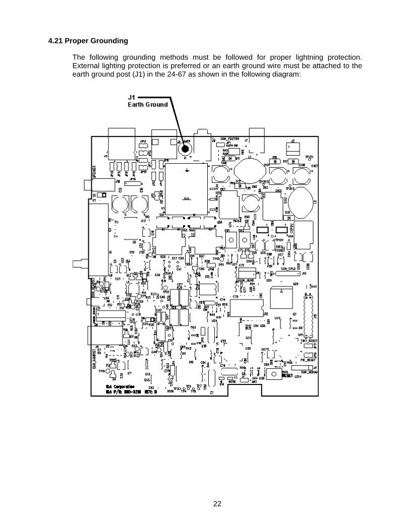
4.21 Proper Grounding
The following grounding methods must be followed for proper lightning protection. External lighting protection is preferred or an earth ground wire must be attached to the earth ground post (J1) in the 24-67 as shown in the following diagram:
22

Proper Grounding (cont.)
On the 24-67 base cabinet, a hole needs to be made to allow the earth ground wire to exit the cabinet and be connected to an earth ground such as a water pipe or other suitable connection. Drill hole only through the plastic cabinet. Drill hole size will be determined by the gauge of wire used for the earth ground. 14awg (or heavier) stranded wire is recommended. Below is a diagram which shows the suggested hole location.
24-67 Remote Base Controller (Rear View)
23
5.0 TROUBLESHOOTING
5.1 Microphone Audio Doesn't Reach the Line
1. The Push-to-Talk (PTT) button should be depressed fully so that the TX indicator is on. If the TX indicator does not turn on, check the handset or desk microphone cord and connector. Note: The Tx indicator will not turn on during intercom.
2. Check to see if pin 5 of U2 goes low (0.7 Vdc or lower) when the PTT switch is depressed. If it does go low and there is still no microphone audio, U2 may be faulty. Replace it with a known working part.
3. The output of the compressor circuit, U6-8, should be biased at 5.0 Vdc with the microphone audio riding on it.
4. The output of the 2175 Hz notch filter circuit, U10-7, should be biased at 5.0 Vdc with the microphone audio riding on it.
5. The output of the summing amplifier, U10-1, should be biased at 5.0 Vdc with the microphone audio riding on it. If not, U10 may be faulty or the TX ADJ EPOT may be turned down too far.
6. The output of the line driver stage, U14-1 and U21-1, should be biased at 6.0 Vdc with the microphone audio riding on it. The line driver is turned on and off by the level present on U14-5 and U21-5. This level should be high (11.0 Vdc or more) when depressing PTT.
5.2 VU Meter Doesn't Function
1. This is a hardware option. Make sure the unit is equipped with it. If no audio appears on the line, refer to section 5.1.
2. Audio is amplified and buffered to the VU meter through U1. The output, U1-14, should be biased at 5.0 Vdc with microphone audio riding on it.
3. If VU audio is present on J10-9, the ribbon cable should be checked for an open.
24
5.3 Control/Alert Tones Do Not Reach the Line
1. All control tones and the alert tones are generated by the microprocessor through the Audio Signaling Processor U19 and its associated components. The tones will be present on U19 pin 20 during times when tones are generated. If not, replace U19 or refer section 5.12.
2. The control tones and the alert tones are fed from the Audio Signaling Processor to EPOT U9B. The intput of EPOT U9B is pin 23, and should have tone(s) present during times when tones are being generated.
3. The tones pass through the tone adjust potentiometer EPOT U9B. Check the adjustment to see if it is set properly. If tones are still not being sent to the line, turn the potentiometer to maximum setting. If tones are present on the wiper arm of EPOT U9B pin 22 and they are still not reaching the line, then the problem is either in the summing amplifier stage U10A or the line driver stage U14 and U21. If so, refer to section 5.1 since microphone audio is probably not reaching the line either.
5.4 Control Tones Have No Effect on the Panel
1. See adjustment procedure for the proper setting of the tone levels.
2. Make sure the 24-67 configuration has been programmed to match what is expected by the panel.
5.5 Line Audio Doesn't Reach the Speaker
1. If a handset is being used, make sure the handset is properly seated in the cradle. Check the operation of the HUHS (Hang Up Hook Switch) by monitoring J8-2 with a DC voltmeter. If a desk microphone is being used, the speaker will remain on continually.
2. If the alternate line or supervisory option is installed make sure the line is connected to the appropriate modular receptacle and that the supervisory function is not selected. Also verify that the appropriate jumpers are installed or not installed.
3. While sending audio into the 24-67 from the line, monitor U5-14. This pin should be biased at 5.0 Vdc with the audio riding on it. If not, make sure the RX ADJ EPOT is set properly. If there is still no audio present on U5-14, U5 or U15 may be faulty.
4. Make sure audio will pass from U16-14 to U16-15 or from U16-2 to U16-3 when bypassing the AGC circuit. With the mute function off, the control pins on one of these audio gates should be high (5.0 Vdc present on U16-16 or U16-1).
25

5.5 Line Audio Doesn't Reach the Speaker (cont.)
6. While receiving audio from the line, U4-7 should be biased at 5.0 Vdc with the audio riding on it.
7. Check to be sure audio passes through the volume control potentiometer R1. After the volume control the audio should be on U1-1. In the speaker path U3-17 should be high (11.0 Vdc or more) and audio should be present at U3 pins 7 and 8.
8. The speaker level adjustment EPOT should be checked to see if it is properly set. U3 is the speaker driver and should have audio present on its output, pins 7 and 8. As a last step make sure JP2 is installed and the speaker connector is mated to J8.
5.6 Earpiece Audio is Not Loud Enough or No Sound
The following solutions assume that the speaker audio is working properly. 1. Check the earpiece level adjustment EPOT for proper adjustment.
2. The output of the earpiece amplifier, U6-7, should be biased at 5.0 Vdc with audio riding on it.
3. Earpiece audio should pass from U16-6 to U16-7 while U16-8 is low (0.7 Vdc or less). At J11-2 there should be approximately 150 mVrms of audio with the handset plugged in.
4. U16-9 should be high (5.0 Vdc) when the 24-67 is configured for a handset. If it is low (0.7 Vdc or less), the 24-67 is configured for a desk microphone and will need to be reconfigured by using the programming software.
5.7 A Constant Hum is Present in the Speaker
1. Check the filter capacitors and voltage regulators in the power supply section. Look for AC ripple riding on the DC voltages.
2. One or more audio adjustments may be turned up too high. Check all applicable adjustments according to the adjustment procedure.
5.8 Background Tone (2175 Hz) Present in Receive Audio
1. Check the 2175 Hz notch filter to see if it is set properly.
2. The 2175 Hz tone may be coming in at too high of a level. Check the levels coming from other parallel remotes.
26
5.9 Parallel TX Indicator Intermittent or Stuck On
1. The 2175 Hz hold tone arriving at the 24-67 is at too high of a level or the detection gain EPOT is set improperly.
5.10 One or More Keys Stuck On or Off
1. Unplug the 24-67 and then plug it back in.
2. Check the ribbon cable between the keypad board and the base board.
3. Microprocessor may be functioning improperly. Refer to section 5.12.
5.11 Faceplate Keys and All LEDs Inoperative
1. Unplug the 24-67 and then plug it back in.
2. Check the ribbon cable between the keypad board and the base board.
3. Microprocessor may be functioning improperly. Refer to section 5.12.
5.12 Microprocessor Functioning Improperly
1. Check for 3.3 Vdc on pins 10, 19, 26 and 38 on the microprocessor (U15).
2. Make sure JP17 and JP19 installed at all times.
27

5.13 Status Messages
The display on the 24-67 is used for displaying the selected frequency, channel, or system and group information. In addition, different status messages are also displayed. The appearance of the different status messages varies depending upon if the 24-67 has the Tone Control option or the MSK Control option and upon the type of display being used (either an LED or an LCD display). Each of the status messages are described below.
24-67 Tone Remote
32 character LCD
LED Description
“DISABLED”
"d" This message is displayed when the current channel is disabled and the Display Configuration Setting "Show Disabled Channels?" is not enabled.
"PROGRAMMING" "P" This is displayed while the 24-67 Tone remote is being programmed.
“*** ERROR ***” "NV MEMORY"
"E" This initialization error is displayed if an error is detected communicating with non-volatile memory or if any of the configuration parameters were set to default during initialization. The 24-67 Remote will automatically reset after displaying this error.
“*** ERROR ***” “I2C POTS”
"E" This initialization error is displayed if an error is detected communicating with the ePots. The 24-67 Remote will automatically reset after displaying this error. Automatically reset after displaying this error.
“*** ERROR ***” “INPUTS / OUTPUTS”
"E" This initialization error is displayed if an error is detected while initializing the inputs and outputs. The 24-67 Remote will automatically reset after displaying this error.
“*** ERROR ***” “TONE PROCESSOR”
"E" This initialization error is displayed if an error is detected communicating with the tone processor. The 24-67 Remote will automatically reset after displaying this error.
“*** ERROR ***” “TONE RESET”
"E" This initialization error is displayed if an error is detected resetting the tone processor. Check that JP17 is installed.
“*** ERROR ***” “NO CHANS ENABLED”
"E" This initialization error is displayed if all channels are disabled.
28
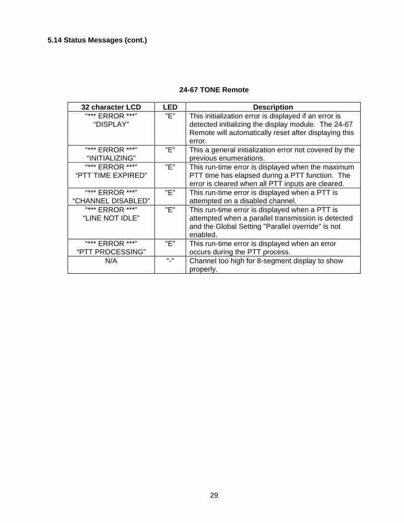
5.14 Status Messages (cont.)
24-67 TONE Remote
32 character LCD LED Description “*** ERROR ***”
“DISPLAY”
"E" This initialization error is displayed if an error is detected initializing the display module. The 24-67 Remote will automatically reset after displaying this error.
“*** ERROR ***” “INITIALIZING”
"E" This a general initialization error not covered by the previous enumerations.
“*** ERROR ***” “PTT TIME EXPIRED”
"E" This run-time error is displayed when the maximum PTT time has elapsed during a PTT function. The error is cleared when all PTT inputs are cleared.
“*** ERROR ***” “CHANNEL DISABLED”
"E" This run-time error is displayed when a PTT is attempted on a disabled channel.
“*** ERROR ***” “LINE NOT IDLE”
"E" This run-time error is displayed when a PTT is attempted when a parallel transmission is detected and the Global Setting "Parallel override" is not enabled.
“*** ERROR ***” “PTT PROCESSING”
"E" This run-time error is displayed when an error occurs during the PTT process.
N/A
"-" Channel too high for 8-segment display to show properly.
29

PARTS LIST
24-67 Base Board 101-2467PRT1
Item Reference Description Part No. Qty.
1 C1,2,3,17,34,39,52,
63,69,71,72,74,75,82, 84,86,97,99,100,103, 107,109,110,113,114, 115,116,117,118,119, 120,122,124,126,127, 128,129,131,134,136, 140,142,143,144,146, 147,148,153,154,155, 156,158,159,160,161, 164,165,166,168,169, 171,173,175,177,180, 181,182,183,184,192, 193,194,195,197,201, 202,203,205,206,207, 208,209,211,214,215, 216,218,219
.1uF 16V X7R CAP 375-2104 88
2 C4,7,8,9,10,12,13,14, 27,31,32,66,70,76,77, 89,90,91,92,93,94,95, 96,111,112,121,123, 125,130,133,135,145, 157,162,163,174,179, 190,191,199,204,217, 220
100pF 50V CAP 375-5101 43
3 C5,22,78 1uF 50V ELEC CAP 381-5105 3 4 C6,11,19,20,23,42,56,
57,200 22pF 50V NPO CAP 373-5220 9
5 C15,16,68,85,101,108 470uF 25V ELEC CAP 381-3471 6 6 C18,30,33 2.2uF 35V ELEC CAP 381-42R2 3 7 C21,35,58,59,61,98 10uF 16V ELEC CAP 381-2100 6 8 C24 47uF 25V ELEC CAP 381-3470 1 9 C25,43,48,53,150,152,
172,187 .47uF 16V Y5V CAP 375-2474 8
10 C26,132 1000pF 50V X7R CAP 375-5102 2 11 C28,29,37,38,40,41,
45,46,50,51 10000pF 100V CAP 372-7103 10
12 C36,176,210,212,213 .22uF 16V Y5V CAP 375-2224 5 13 C44,47,49,54,55,62,
104 1uF 35V TANT CAP 392-4105 7
14 C60,138,196 330pF 50V CAP 375-5331 3 15 C64,65 18pF 50V CAP 375-5180 2 16 C67 2700pF 50V X7R CAP 375-5272 1
30
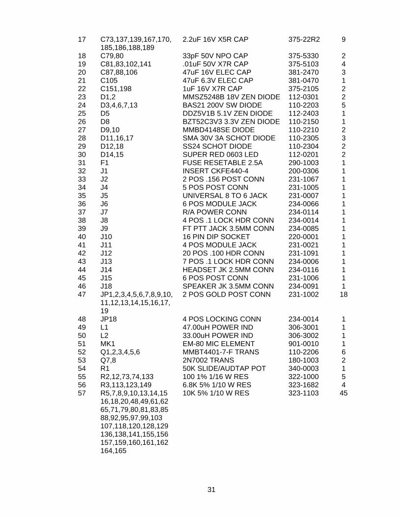
17 C73,137,139,167,170,
185,186,188,189 2.2uF 16V X5R CAP 375-22R2 9
18 C79,80 33pF 50V NPO CAP 375-5330 2 19 C81,83,102,141 .01uF 50V X7R CAP 375-5103 4 20 C87,88,106 47uF 16V ELEC CAP 381-2470 3 21 C105 47uF 6.3V ELEC CAP 381-0470 1 22 C151,198 1uF 16V X7R CAP 375-2105 2 23 D1,2 MMSZ5248B 18V ZEN DIODE 112-0301 2 24 D3,4,6,7,13 BAS21 200V SW DIODE 110-2203 5 25 D5 DDZ5V1B 5.1V ZEN DIODE 112-2403 1 26 D8 BZT52C3V3 3.3V ZEN DIODE 110-2150 1 27 D9,10 MMBD4148SE DIODE 110-2210 2 28 D11,16,17 SMA 30V 3A SCHOT DIODE 110-2305 3 29 D12,18 SS24 SCHOT DIODE 110-2304 2 30 D14,15 SUPER RED 0603 LED 112-0201 2 31 F1 FUSE RESETABLE 2.5A 290-1003 1 32 J1 INSERT CKFE440-4 200-0306 1 33 J2 2 POS .156 POST CONN 231-1067 1 34 J4 5 POS POST CONN 231-1005 1 35 J5 UNIVERSAL 8 TO 6 JACK 231-0007 1 36 J6 6 POS MODULE JACK 234-0066 1 37 J7 R/A POWER CONN 234-0114 1 38 J8 4 POS .1 LOCK HDR CONN 234-0014 1 39 J9 FT PTT JACK 3.5MM CONN 234-0085 1 40 J10 16 PIN DIP SOCKET 220-0001 1 41 J11 4 POS MODULE JACK 231-0021 1 42 J12 20 POS .100 HDR CONN 231-1091 1 43 J13 7 POS .1 LOCK HDR CONN 234-0006 1 44 J14 HEADSET JK 2.5MM CONN 234-0116 1 45 J15 6 POS POST CONN 231-1006 1 46 J18 SPEAKER JK 3.5MM CONN 234-0091 1 47 JP1,2,3,4,5,6,7,8,9,10,
11,12,13,14,15,16,17, 19
2 POS GOLD POST CONN 231-1002 18
48 JP18 4 POS LOCKING CONN 234-0014 1 49 L1 47.00uH POWER IND 306-3001 1 50 L2 33.00uH POWER IND 306-3002 1 51 MK1 EM-80 MIC ELEMENT 901-0010 1 52 Q1,2,3,4,5,6 MMBT4401-7-F TRANS 110-2206 6 53 Q7,8 2N7002 TRANS 180-1003 2 54 R1 50K SLIDE/AUDTAP POT 340-0003 1 55 R2,12,73,74,133 100 1% 1/16 W RES 322-1000 5 56 R3,113,123,149 6.8K 5% 1/10 W RES 323-1682 4 57 R5,7,8,9,10,13,14,15
16,18,20,48,49,61,62 65,71,79,80,81,83,85 88,92,95,97,99,103 107,118,120,128,129 136,138,141,155,156 157,159,160,161,162 164,165
10K 5% 1/10 W RES 323-1103 45
31
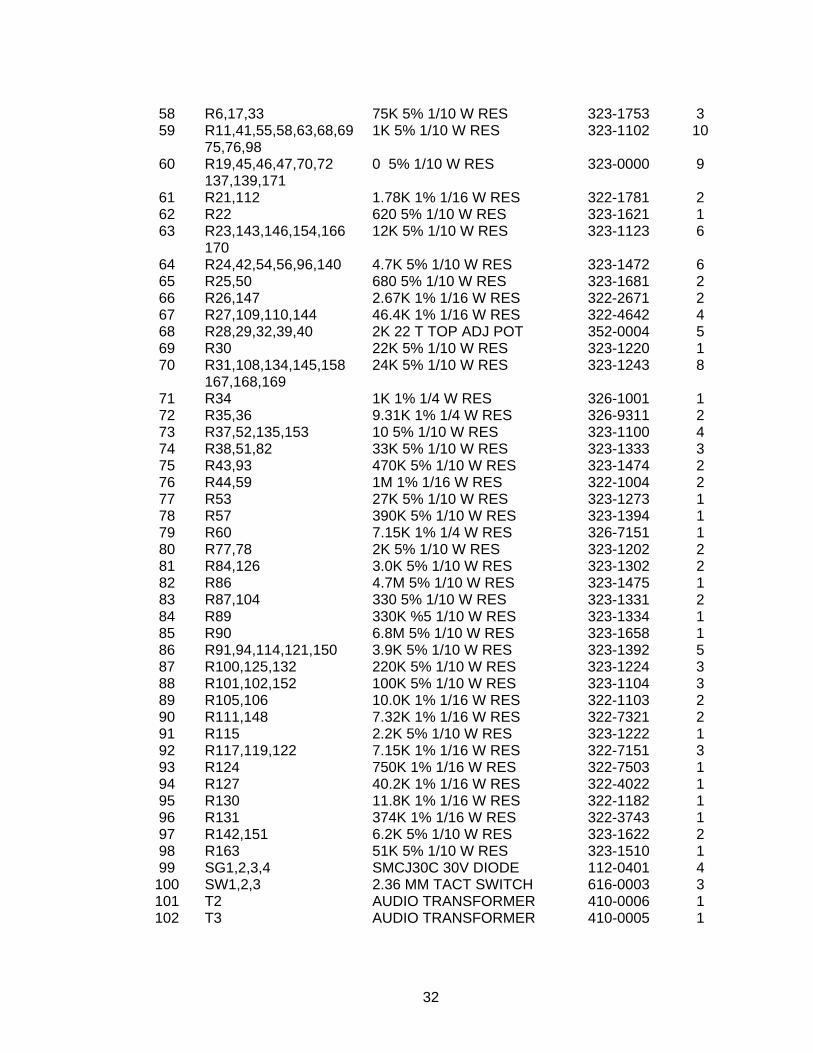
58 R6,17,33 75K 5% 1/10 W RES 323-1753 3 59 R11,41,55,58,63,68,69
75,76,98 1K 5% 1/10 W RES 323-1102 10
60 R19,45,46,47,70,72 137,139,171
0 5% 1/10 W RES 323-0000 9
61 R21,112 1.78K 1% 1/16 W RES 322-1781 2 62 R22 620 5% 1/10 W RES 323-1621 1 63 R23,143,146,154,166
170 12K 5% 1/10 W RES 323-1123 6
64 R24,42,54,56,96,140 4.7K 5% 1/10 W RES 323-1472 6 65 R25,50 680 5% 1/10 W RES 323-1681 2 66 R26,147 2.67K 1% 1/16 W RES 322-2671 2 67 R27,109,110,144 46.4K 1% 1/16 W RES 322-4642 4 68 R28,29,32,39,40 2K 22 T TOP ADJ POT 352-0004 5 69 R30 22K 5% 1/10 W RES 323-1220 1 70 R31,108,134,145,158
167,168,169 24K 5% 1/10 W RES 323-1243 8
71 R34 1K 1% 1/4 W RES 326-1001 1 72 R35,36 9.31K 1% 1/4 W RES 326-9311 2 73 R37,52,135,153 10 5% 1/10 W RES 323-1100 4 74 R38,51,82 33K 5% 1/10 W RES 323-1333 3 75 R43,93 470K 5% 1/10 W RES 323-1474 2 76 R44,59 1M 1% 1/16 W RES 322-1004 2 77 R53 27K 5% 1/10 W RES 323-1273 1 78 R57 390K 5% 1/10 W RES 323-1394 1 79 R60 7.15K 1% 1/4 W RES 326-7151 1 80 R77,78 2K 5% 1/10 W RES 323-1202 2 81 R84,126 3.0K 5% 1/10 W RES 323-1302 2 82 R86 4.7M 5% 1/10 W RES 323-1475 1 83 R87,104 330 5% 1/10 W RES 323-1331 2 84 R89 330K %5 1/10 W RES 323-1334 1 85 R90 6.8M 5% 1/10 W RES 323-1658 1 86 R91,94,114,121,150 3.9K 5% 1/10 W RES 323-1392 5 87 R100,125,132 220K 5% 1/10 W RES 323-1224 3 88 R101,102,152 100K 5% 1/10 W RES 323-1104 3 89 R105,106 10.0K 1% 1/16 W RES 322-1103 2 90 R111,148 7.32K 1% 1/16 W RES 322-7321 2 91 R115 2.2K 5% 1/10 W RES 323-1222 1 92 R117,119,122 7.15K 1% 1/16 W RES 322-7151 3 93 R124 750K 1% 1/16 W RES 322-7503 1 94 R127 40.2K 1% 1/16 W RES 322-4022 1 95 R130 11.8K 1% 1/16 W RES 322-1182 1 96 R131 374K 1% 1/16 W RES 322-3743 1 97 R142,151 6.2K 5% 1/10 W RES 323-1622 2 98 R163 51K 5% 1/10 W RES 323-1510 1 99 SG1,2,3,4 SMCJ30C 30V DIODE 112-0401 4
100 SW1,2,3 2.36 MM TACT SWITCH 616-0003 3 101 T2 AUDIO TRANSFORMER 410-0006 1 102 T3 AUDIO TRANSFORMER 410-0005 1
32
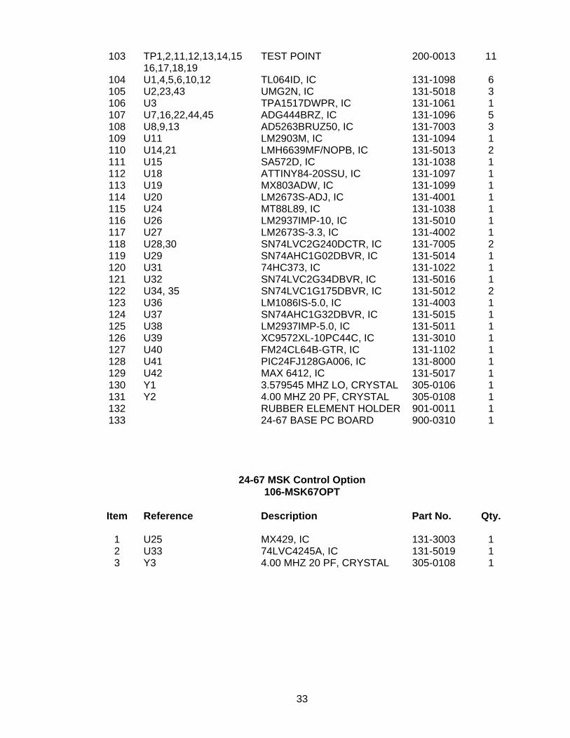
103 TP1,2,11,12,13,14,15
16,17,18,19 TEST POINT 200-0013 11
104 U1,4,5,6,10,12 TL064ID, IC 131-1098 6 105 U2,23,43 UMG2N, IC 131-5018 3 106 U3 TPA1517DWPR, IC 131-1061 1 107 U7,16,22,44,45 ADG444BRZ, IC 131-1096 5 108 U8,9,13 AD5263BRUZ50, IC 131-7003 3 109 U11 LM2903M, IC 131-1094 1 110 U14,21 LMH6639MF/NOPB, IC 131-5013 2 111 U15 SA572D, IC 131-1038 1 112 U18 ATTINY84-20SSU, IC 131-1097 1 113 U19 MX803ADW, IC 131-1099 1 114 U20 LM2673S-ADJ, IC 131-4001 1 115 U24 MT88L89, IC 131-1038 1 116 U26 LM2937IMP-10, IC 131-5010 1 117 U27 LM2673S-3.3, IC 131-4002 1 118 U28,30 SN74LVC2G240DCTR, IC 131-7005 2 119 U29 SN74AHC1G02DBVR, IC 131-5014 1 120 U31 74HC373, IC 131-1022 1 121 U32 SN74LVC2G34DBVR, IC 131-5016 1 122 U34, 35 SN74LVC1G175DBVR, IC 131-5012 2 123 U36 LM1086IS-5.0, IC 131-4003 1 124 U37 SN74AHC1G32DBVR, IC 131-5015 1 125 U38 LM2937IMP-5.0, IC 131-5011 1 126 U39 XC9572XL-10PC44C, IC 131-3010 1 127 U40 FM24CL64B-GTR, IC 131-1102 1 128 U41 PIC24FJ128GA006, IC 131-8000 1 129 U42 MAX 6412, IC 131-5017 1 130 Y1 3.579545 MHZ LO, CRYSTAL 305-0106 1 131 Y2 4.00 MHZ 20 PF, CRYSTAL 305-0108 1 132 RUBBER ELEMENT HOLDER 901-0011 1 133 24-67 BASE PC BOARD 900-0310 1
24-67 MSK Control Option 106-MSK67OPT
Item Reference Description Part No. Qty.
1 U25 MX429, IC 131-3003 1 2 U33 74LVC4245A, IC 131-5019 1 3 Y3 4.00 MHZ 20 PF, CRYSTAL 305-0108 1
33
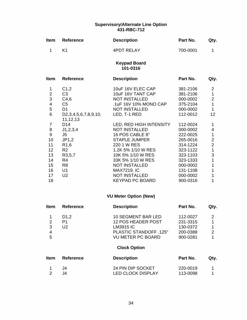
Supervisory/Alternate Line Option 431-RBC-712
Item Reference Description Part No. Qty.
1 K1 4PDT RELAY 700-0001 1
Keypad Board 101-0316
Item Reference Description Part No. Qty.
1 C1,2 10uF 16V ELEC CAP 381-2106 2 2 C3 10uF 16V TANT CAP 381-2106 1 3 C4,6 NOT INSTALLED 000-0002 2 4 C5 .1uF 16V 10% MONO CAP 375-2104 1 5 D1 NOT INSTALLED 000-0002 1 6 D2,3,4,5,6,7,8,9,10,
11,12,13 LED, T-1 RED 112-0012 12
7 D14 LED, RED HIGH INTENSITY 112-0024 1 8 J1,2,3,4 NOT INSTALLED 000-0002 4 9 J5 16 POS CABLE 8” 222-0025 1
10 JP1,2 STAPLE JUMPER 265-0016 2 11 R1,6 220 1 W RES 314-1224 2 12 R2 1.2K 5% 1/10 W RES 323-1122 1 13 R3,5,7 10K 5% 1/10 W RES 323-1103 3 14 R4 33K 5% 1/10 W RES 323-1333 1 15 R8 NOT INSTALLED 000-0002 1 16 U1 MAX7219, IC 131-1108 1 17 U2 NOT INSTALLED 000-0002 1 18 KEYPAD PC BOARD 900-0316 1
VU Meter Option (New)
Item Reference Description Part No. Qty.
1 D1,2 10 SEGMENT BAR LED 112-0027 2 2 P1 12 POS HEADER POST 231-3315 1 3 U2 LM3915 IC 130-0372 1 4 PLASTIC STANDOFF .125" 200-0388 2 5 VU METER PC BOARD 900-0281 1
Clock Option
Item Reference Description Part No. Qty.
1 J4 24 PIN DIP SOCKET 220-0019 1 2 J4 LED CLOCK DISPLAY 113-0098 1
34

Frequency Display Option
Item Reference Description Part No. Qty.
1 D1 7 SEG RED, DISPLAY 113-0099 1 2 D1 14 PIN DIP SOCKET 220-0002 1 3 J2 6 POS BOTTOM ENTRY CON 231-1116 2
LCD Option
Item Reference Description Part No. Qty. 1 C4,6 .1uF 16V 10% MONO CAP 375-2104 2 2 J1 6 POS RECEPTACLE 231-1116 2 3 J3 8 POS RECEPTACLE 231-3008 2 4 R8 10K 1 TURN POT 351-1103 1 5 U2 74HC595, IC 131-1107 1 6 LCD 32 CHARACTER 113-0106 1 7 PLASTIC STAND OFF 1/8” 200-0311 4 8 16 POS HEADER POST 231-3116 1
DC Power Cable Option
Item Description Part No. Qty.
1 2 POS .156 RECEPTACLE 233-0024 1 2 CABLE TIE (SHORT) 200-0081 1 3 2 COND. 20ga. CABLE 800-1106 5’
External Encode/Decode Cable Option 431-RBC-702
Item Description Part No. Qty.
1 CABLE TIE (SHORT) 200-0081 1 2 9 COND. 22ga. CABLE 222-0034 3’ 3 7 POS .1” RECEPTACLE 234-0007 1
35
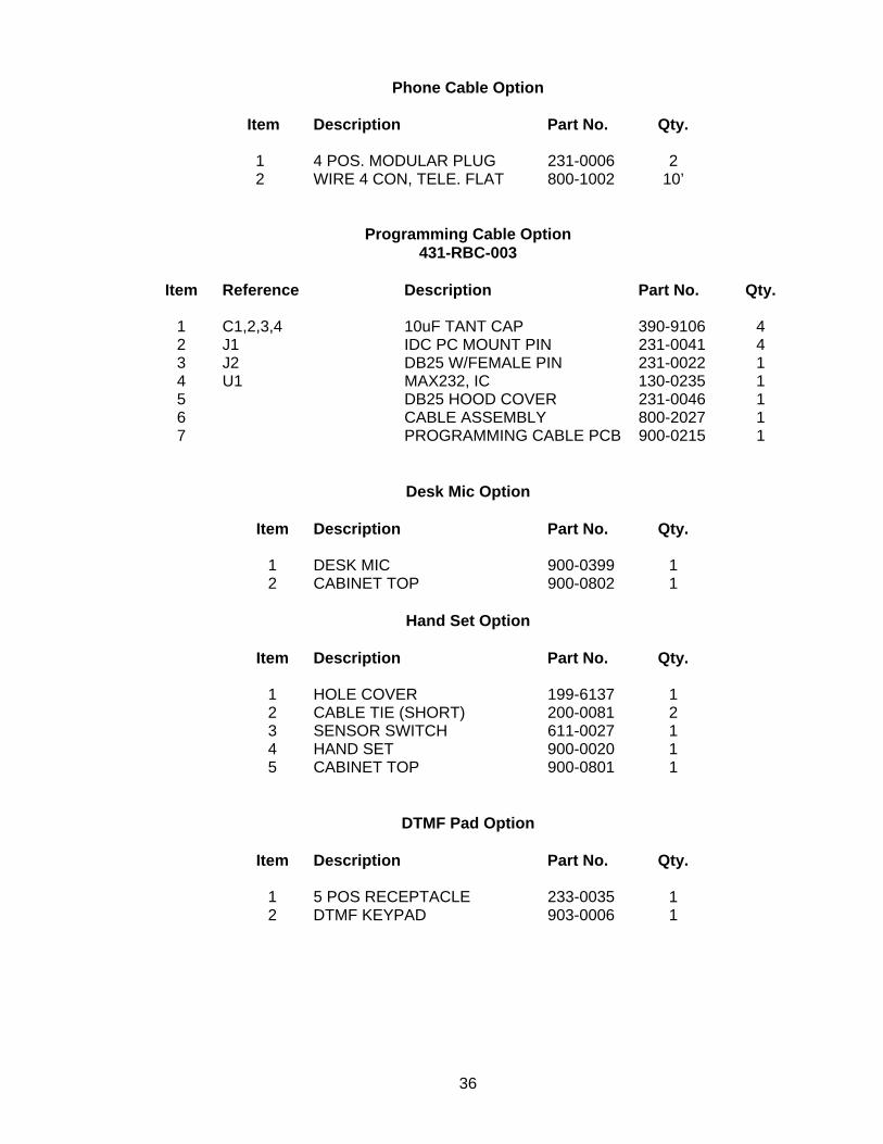
Phone Cable Option
Item Description Part No. Qty. 1 4 POS. MODULAR PLUG 231-0006 2 2 WIRE 4 CON, TELE. FLAT 800-1002 10’
Programming Cable Option 431-RBC-003
Item Reference Description Part No. Qty.
1 C1,2,3,4 10uF TANT CAP 390-9106 4 2 J1 IDC PC MOUNT PIN 231-0041 4 3 J2 DB25 W/FEMALE PIN 231-0022 1 4 U1 MAX232, IC 130-0235 1 5 DB25 HOOD COVER 231-0046 1 6 CABLE ASSEMBLY 800-2027 1 7 PROGRAMMING CABLE PCB 900-0215 1
Desk Mic Option
Item Description Part No. Qty.
1 DESK MIC 900-0399 1 2 CABINET TOP 900-0802 1
Hand Set Option
Item Description Part No. Qty.
1 HOLE COVER 199-6137 1 2 CABLE TIE (SHORT) 200-0081 2 3 SENSOR SWITCH 611-0027 1 4 HAND SET 900-0020 1 5 CABINET TOP 900-0801 1
DTMF Pad Option
Item Description Part No. Qty.
1 5 POS RECEPTACLE 233-0035 1 2 DTMF KEYPAD 903-0006 1
36
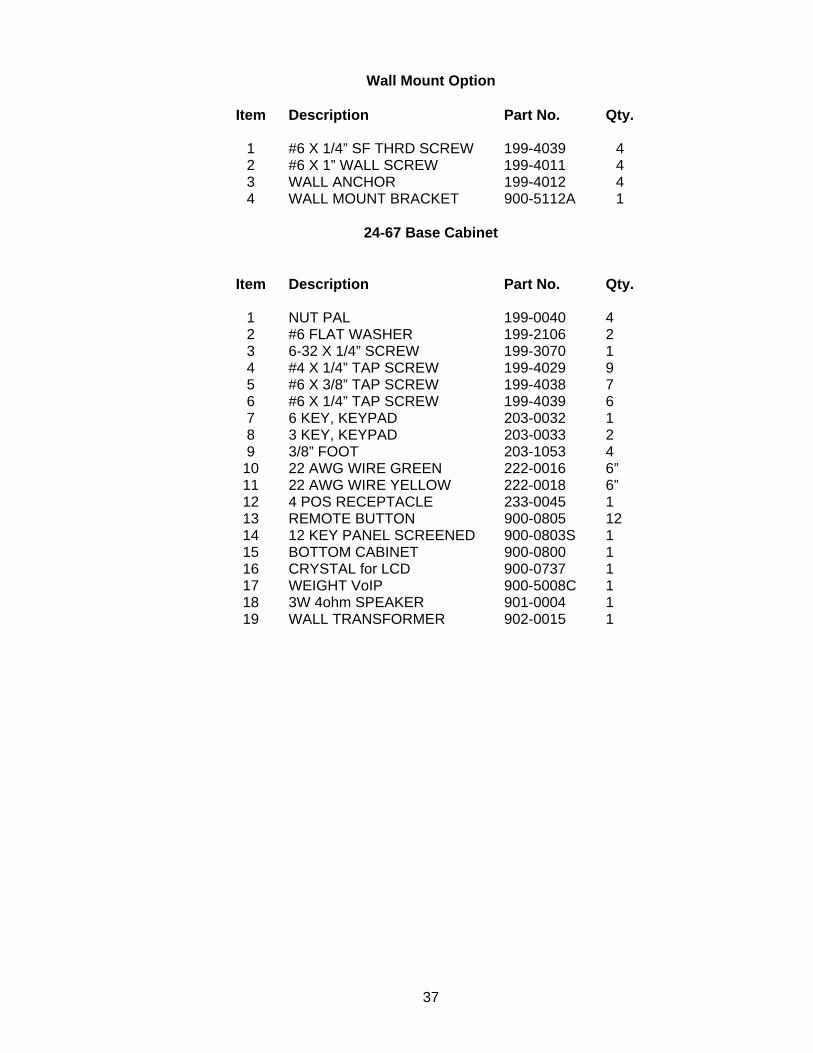
Wall Mount Option
Item Description Part No. Qty.
1 #6 X 1/4” SF THRD SCREW 199-4039 4 2 #6 X 1” WALL SCREW 199-4011 4 3 WALL ANCHOR 199-4012 4 4 WALL MOUNT BRACKET 900-5112A 1
24-67 Base Cabinet
Item Description Part No. Qty.
1 NUT PAL 199-0040 4 2 #6 FLAT WASHER 199-2106 2 3 6-32 X 1/4” SCREW 199-3070 1 4 #4 X 1/4” TAP SCREW 199-4029 9 5 #6 X 3/8” TAP SCREW 199-4038 7 6 #6 X 1/4” TAP SCREW 199-4039 6 7 6 KEY, KEYPAD 203-0032 1 8 3 KEY, KEYPAD 203-0033 2 9 3/8” FOOT 203-1053 4
10 22 AWG WIRE GREEN 222-0016 6” 11 22 AWG WIRE YELLOW 222-0018 6” 12 4 POS RECEPTACLE 233-0045 1 13 REMOTE BUTTON 900-0805 12 14 12 KEY PANEL SCREENED 900-0803S 1 15 BOTTOM CABINET 900-0800 1 16 CRYSTAL for LCD 900-0737 1 17 WEIGHT VoIP 900-5008C 1 18 3W 4ohm SPEAKER 901-0004 1 19 WALL TRANSFORMER 902-0015 1
37

TEST MODE APPENDIX
Keypad Layouts
The 24-67 Test Mode uses different keypad layouts to accept input from the User. The following are the non-test specific keypad layouts:
General Keypad Layout
The General Keypad Layout is used when referencing the keypad by key number. Key 1 Key 2 Key 3
Key 4 Key 5 Key 6 Key 7 Key 8 Key 9 Key 10 Key 11 Key 12
Selection Keypad Layout
The Selection Keypad Layout is used when selecting values from a list.
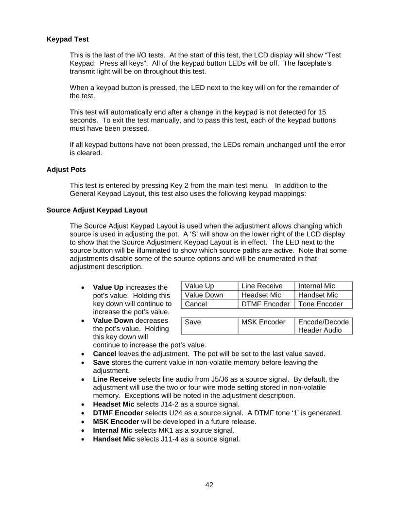
Up Down Cancel Ok
• Up increases a value or moves up in the list of options
• Down decreases a value or moves down in the
list of options.
• Cancel stops the current operation.
• Ok stops the current operation and saves the result if possible. It is also used to answer a Yes or No question as Yes.
Entering Test Mode
The Test Mode is included in the application code. The Test Mode is reached in one of two ways:
• Press Key 1 and Key 3 simultaneously before the main run-mode screen is displayed.
• Press PCB switch SW2 at any time the unit is operating.
38
Test Mode Main Menu
When entering Test Mode or returning from a Test Menu Item, “Choose Test” will be displayed on the 24-67 LCD Display. At this point, all outputs will be off. The audio gates will be set to allow audio from the line to the audio processors. All other gates will be off. Select a test by pressing its corresponding number using the General Keypad Layout.
1. I/O Tests 2. Adjust Pots 3. Sequential Tone Encode 4. Tone Encode 5. DTMF Encode (DTMF is not available with product Rev.C and newer units) 6. Sequential Tone Decode 7. DTMF Decode (DTMF is not available with product Rev.C and newer units) 8. Serial Port 9. Set Parameters 10. Reset to Defaults
I/O Tests
This is a series of short tests to test the inputs and outputs of the 24-67, as well as insure that the rest of the tests operate smoothly. This test is entered by pressing Key 1 from the main test menu.
Test Outputs
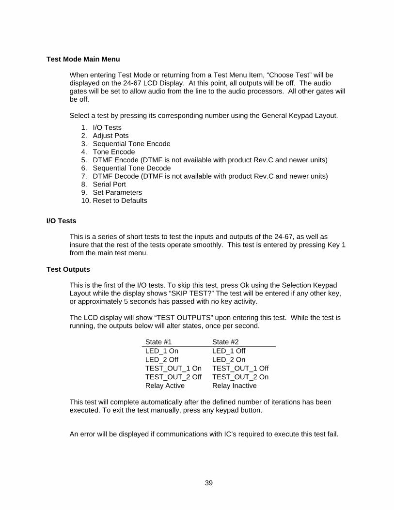
This is the first of the I/O tests. To skip this test, press Ok using the Selection Keypad Layout while the display shows “SKIP TEST?” The test will be entered if any other key, or approximately 5 seconds has passed with no key activity. The LCD display will show “TEST OUTPUTS” upon entering this test. While the test is running, the outputs below will alter states, once per second.
State #1 State #2 LED_1 On LED_1 Off LED_2 Off LED_2 On TEST_OUT_1 On TEST_OUT_1 Off TEST_OUT_2 Off TEST_OUT_2 On Relay Active Relay Inactive
This test will complete automatically after the defined number of iterations has been executed. To exit the test manually, press any keypad button.
An error will be displayed if communications with IC’s required to execute this test fail.
39
Test SW1 & SW2
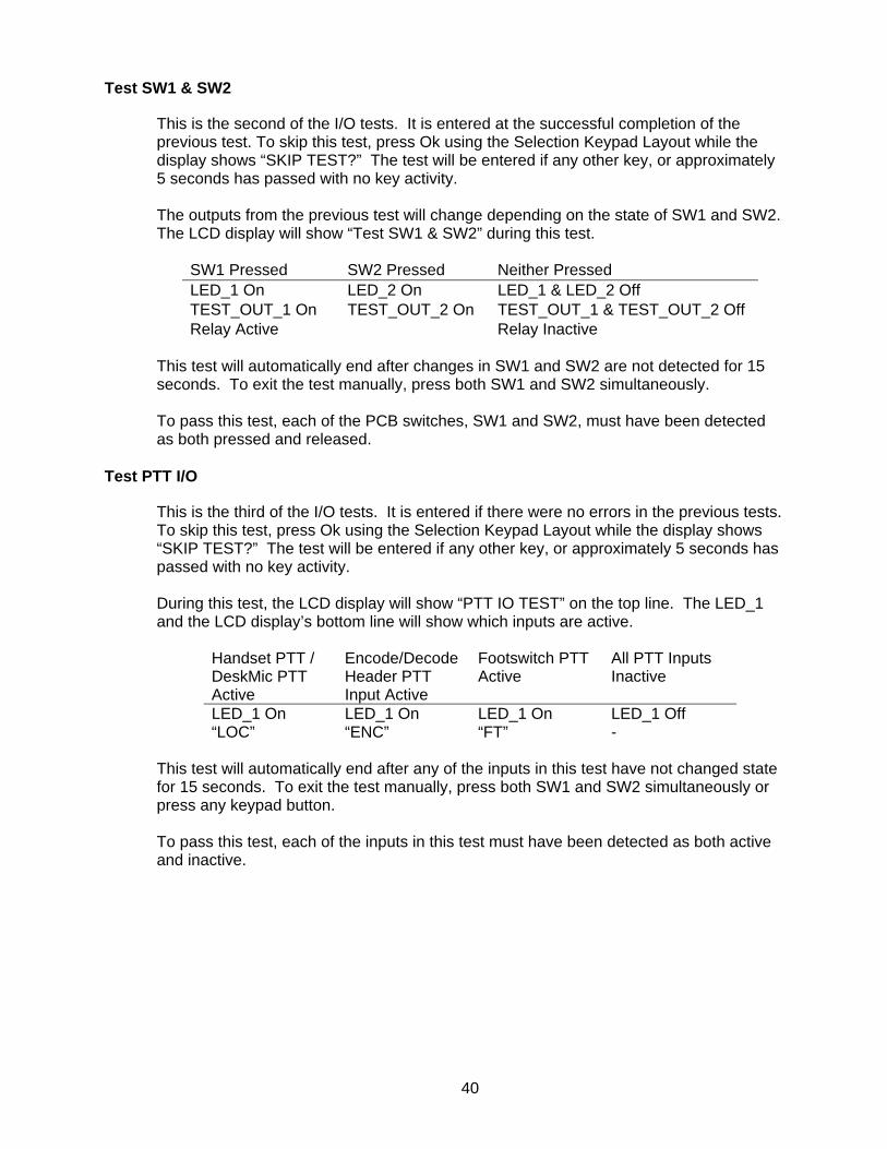
This is the second of the I/O tests. It is entered at the successful completion of the previous test. To skip this test, press Ok using the Selection Keypad Layout while the display shows “SKIP TEST?” The test will be entered if any other key, or approximately 5 seconds has passed with no key activity. The outputs from the previous test will change depending on the state of SW1 and SW2. The LCD display will show “Test SW1 & SW2” during this test.
SW1 Pressed SW2 Pressed Neither Pressed LED_1 On LED_2 On LED_1 & LED_2 Off TEST_OUT_1 On TEST_OUT_2 On TEST_OUT_1 & TEST_OUT_2 Off Relay Active Relay Inactive
This test will automatically end after changes in SW1 and SW2 are not detected for 15 seconds. To exit the test manually, press both SW1 and SW2 simultaneously. To pass this test, each of the PCB switches, SW1 and SW2, must have been detected as both pressed and released.
Test PTT I/O
This is the third of the I/O tests. It is entered if there were no errors in the previous tests. To skip this test, press Ok using the Selection Keypad Layout while the display shows “SKIP TEST?” The test will be entered if any other key, or approximately 5 seconds has passed with no key activity. During this test, the LCD display will show “PTT IO TEST” on the top line. The LED_1 and the LCD display’s bottom line will show which inputs are active.
Handset PTT / DeskMic PTT Active
Encode/Decode Header PTT Input Active
Footswitch PTT Active
All PTT Inputs Inactive
LED_1 On LED_1 On LED_1 On LED_1 Off “LOC” “ENC” “FT” -
This test will automatically end after any of the inputs in this test have not changed state for 15 seconds. To exit the test manually, press both SW1 and SW2 simultaneously or press any keypad button. To pass this test, each of the inputs in this test must have been detected as both active and inactive.
40

Hookswitch Test
This is the fourth of the I/O tests. It is entered if there were no errors first two tests. To skip this test, press Ok using the Selection Keypad Layout while the display shows “SKIP TEST?” The test will be entered if any other key, or approximately 5 seconds has passed with no key activity. During this test, the LCD display will show “TEST HOOK SWITCH” on the top line. The LED_2 and the LCD display’s bottom line will if the input is active.
Handset Hook Active
Handset Hook Inactive
LED_2 On LED_2 Off “ACTIVE” -
This test will automatically end after any of the inputs in this test have not changed state for 15 seconds. To exit the test manually, press both SW1 and SW2 simultaneously or press any keypad button. To pass this test, each of the inputs in this test must have been detected as both active and inactive.
Monitor Test
This is the fifth of the I/O tests. It is entered if there were no errors first two tests. To skip this test, press Ok using the Selection Keypad Layout while the display shows “SKIP TEST?” The test will be entered if any other key, or approximately 5 seconds has passed with no key activity. During this test, the LCD display will show “TEST MONITOR” on the top line. The LED_2 and the LCD display’s bottom line will show which inputs are active.
Deskmic Monitor Active
Deskmic Monitor Inactive
LED_2 On LED_2 Off “ACTIVE” -
This test will automatically end after any of the inputs in this test have not changed state for 15 seconds. To exit the test manually, press both SW1 and SW2 simultaneously or press any keypad button. To pass this test, each of the inputs in this test must have been detected as both active and inactive.
41
Keypad Test
This is the last of the I/O tests. At the start of this test, the LCD display will show “Test Keypad. Press all keys”. All of the keypad button LEDs will be off. The faceplate’s transmit light will be on throughout this test. When a keypad button is pressed, the LED next to the key will on for the remainder of the test. This test will automatically end after a change in the keypad is not detected for 15 seconds. To exit the test manually, and to pass this test, each of the keypad buttons must have been pressed. If all keypad buttons have not been pressed, the LEDs remain unchanged until the error is cleared.
Adjust Pots
This test is entered by pressing Key 2 from the main test menu. In addition to the General Keypad Layout, this test also uses the following keypad mappings:
Source Adjust Keypad Layout
The Source Adjust Keypad Layout is used when the adjustment allows changing which source is used in adjusting the pot. A ‘S’ will show on the lower right of the LCD display to show that the Source Adjustment Keypad Layout is in effect. The LED next to the source button will be illuminated to show which source paths are active. Note that some adjustments disable some of the source options and will be enumerated in that adjustment description.
• Value Up increases the pot’s value. Holding this key down will continue to increase the pot’s value.
• Value Down decreases the pot’s value. Holding this key down will continue to increase the pot’s value.
Value Up Line Receive Internal Mic Value Down Headset Mic Handset Mic Cancel DTMF Encoder Tone Encoder Save MSK Encoder Encode/Decode
Header Audio
• Cancel leaves the adjustment. The pot will be set to the last value saved. • Save stores the current value in non-volatile memory before leaving the
adjustment. • Line Receive selects line audio from J5/J6 as a source signal. By default, the
adjustment will use the two or four wire mode setting stored in non-volatile memory. Exceptions will be noted in the adjustment description.
• Headset Mic selects J14-2 as a source signal. • DTMF Encoder selects U24 as a source signal. A DTMF tone ‘1’ is generated. • MSK Encoder will be developed in a future release. • Internal Mic selects MK1 as a source signal. • Handset Mic selects J11-4 as a source signal.
42

Source Adjust Keypad Layout (cont.)
• Tone Encoder selects U19 as a source signal. If Guard Tone is required for the adjustment, a 2175 Hz tone is generated. If Guard Tone is not required for the adjustment, a 1050 Hz tone is generated.
• Encode / Decode Header Audio selects J13-5 as a source signal.
Destination Adjust Keypad Layout
The Destination Adjust Keypad Layout is used when the adjustment allows changing which destination to use when adjusting the pot. A ‘D’ will show on the lower right of the LCD display to show that the Destination Adjust Keypad Layout is in effect. The LED next to the destination button will be illuminated to show which destination paths are active. Note that some adjustments disable some of the destination options and will be enumerated in that adjustment description.
• Value Up increases the pot’s value. Holding this key down will continue to increase the pot’s value.
• Value Down decreases the pot’s value. Holding this key down will continue to increase the pot’s value.
Value Up Line Transmit Speaker Value Down Headset Ear Handset Ear Cancel Save
• Cancel leaves the adjustment. The pot will be set to the last value saved. • Save stores the current value in non-volatile memory before leaving the
adjustment. • Line Transmit selects line audio to J5/J6 as a destination for the signal. • Headset Ear selects J14-4 (Headset Earpiece) as a destination for the signal. • Speaker selects J8 and J18 as a destination for the signal. Note that this
destination is dependent on the setting of JP2 and JP18. • Handset Ear selects J11-2 (Handset Earpiece) as a destination for the signal,
regardless of the corresponding configuration value stored in non-volatile memory.
Pot Selection
Select a pot to adjust by pressing its corresponding number using the General Keypad Layout.
1. Internal Mic (U13B) 2. Handset Mic (U13C) 3. Transmit Audio (U9C) 4. DTMF Encoder (U9D) 5. Tone Encoder (U9B) 6. MSK Encoder (U9A) 7. 2 Wire (U8C) 8. 4 Wire (U8B) 9. Speaker (U8A) 10. Headset Ear (U8D) 11. Handset Ear (U13D) 12. 2175Hz Detect (U13A)
43
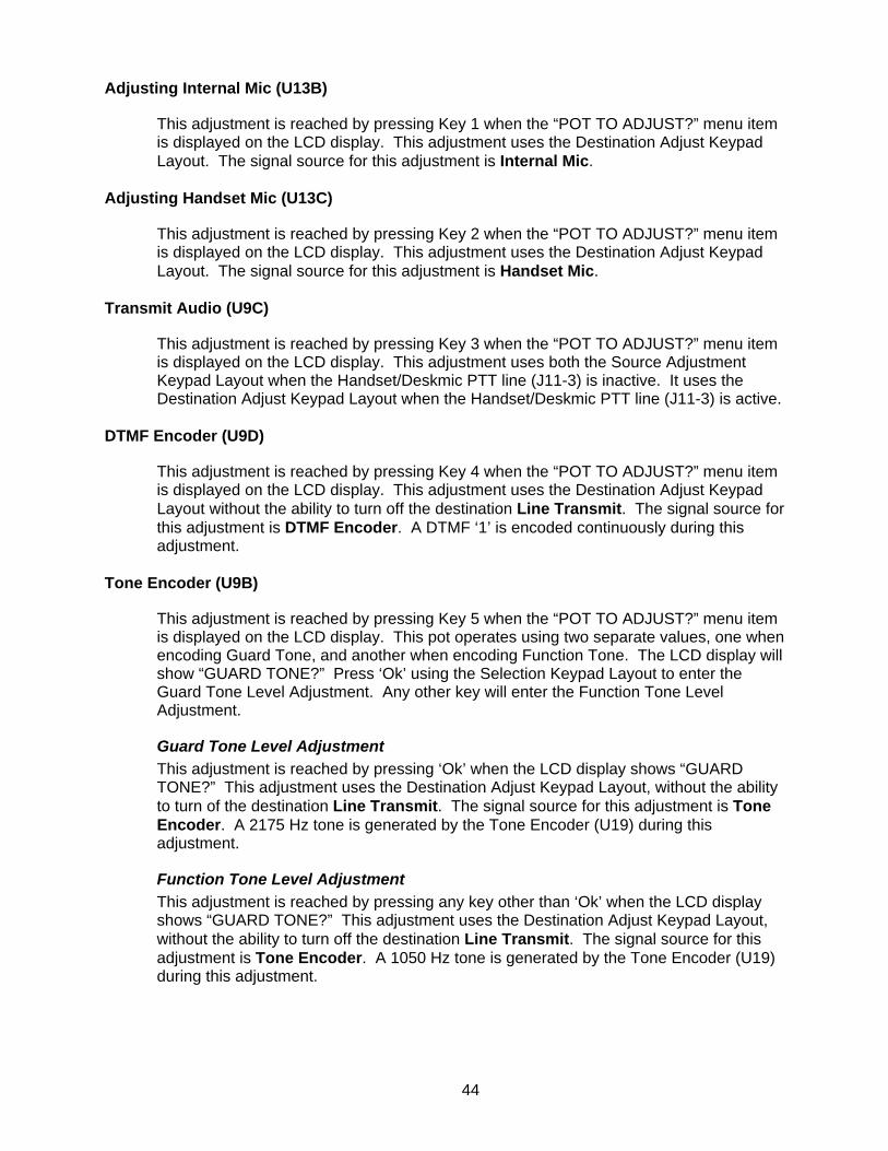
Adjusting Internal Mic (U13B)
This adjustment is reached by pressing Key 1 when the “POT TO ADJUST?” menu item is displayed on the LCD display. This adjustment uses the Destination Adjust Keypad Layout. The signal source for this adjustment is Internal Mic.
Adjusting Handset Mic (U13C)
This adjustment is reached by pressing Key 2 when the “POT TO ADJUST?” menu item is displayed on the LCD display. This adjustment uses the Destination Adjust Keypad Layout. The signal source for this adjustment is Handset Mic.
Transmit Audio (U9C)
This adjustment is reached by pressing Key 3 when the “POT TO ADJUST?” menu item is displayed on the LCD display. This adjustment uses both the Source Adjustment Keypad Layout when the Handset/Deskmic PTT line (J11-3) is inactive. It uses the Destination Adjust Keypad Layout when the Handset/Deskmic PTT line (J11-3) is active.
DTMF Encoder (U9D)
This adjustment is reached by pressing Key 4 when the “POT TO ADJUST?” menu item is displayed on the LCD display. This adjustment uses the Destination Adjust Keypad Layout without the ability to turn off the destination Line Transmit. The signal source for this adjustment is DTMF Encoder. A DTMF ‘1’ is encoded continuously during this adjustment.
Tone Encoder (U9B)
This adjustment is reached by pressing Key 5 when the “POT TO ADJUST?” menu item is displayed on the LCD display. This pot operates using two separate values, one when encoding Guard Tone, and another when encoding Function Tone. The LCD display will show “GUARD TONE?” Press ‘Ok’ using the Selection Keypad Layout to enter the Guard Tone Level Adjustment. Any other key will enter the Function Tone Level Adjustment.
Guard Tone Level Adjustment This adjustment is reached by pressing ‘Ok’ when the LCD display shows “GUARD TONE?” This adjustment uses the Destination Adjust Keypad Layout, without the ability to turn of the destination Line Transmit. The signal source for this adjustment is Tone Encoder. A 2175 Hz tone is generated by the Tone Encoder (U19) during this adjustment.
Function Tone Level Adjustment This adjustment is reached by pressing any key other than ‘Ok’ when the LCD display shows “GUARD TONE?” This adjustment uses the Destination Adjust Keypad Layout, without the ability to turn off the destination Line Transmit. The signal source for this adjustment is Tone Encoder. A 1050 Hz tone is generated by the Tone Encoder (U19) during this adjustment.
44

MSK Encoder (U9A)
This adjustment is reached by pressing Key 6 when the “POT TO ADJUST?” menu item is displayed on the LCD display. This adjustment uses the Destination Adjust Keypad Layout, with Line Transmit, Headset Ear, Speaker, and Handset Ear disabled. This adjustment will be refined in a future version of the 24-67.
2 Wire (U8C)
This adjustment is reached by pressing Key 7 when the “POT TO ADJUST?” menu item is displayed on the LCD display. This adjustment uses the Destination Adjust Keypad Layout without the ability to set the destination to Line Transmit. The signal source for this adjustment is Line Receive. The Two wire mode will be used for this test regardless of the setting stored in non-volatile memory.
4 Wire (U8B)
This adjustment is reached by pressing Key 8 when the “POT TO ADJUST?” menu item is displayed on the LCD display. This adjustment uses the Destination Adjust Keypad Layout without the ability to set the destination to Line Transmit. The signal source for this adjustment is Line Receive. The Four wire mode will be used for this test regardless of the setting stored in non-volatile memory.
Speaker (U8A)
This adjustment is reached by pressing Key 9 when the “POT TO ADJUST?” menu item is displayed on the LCD display. This adjustment uses the Source Adjust Keypad Layout. The destination for this adjustment is Speaker.
Headset Ear (U8D)
This adjustment is reached by pressing Key 10 when the “POT TO ADJUST?” menu item is displayed on the LCD display. This adjustment uses the Source Adjust Keypad Layout. The destination for this adjustment is Headset Ear.
Handset Ear (U13D)
This adjustment is reached by pressing Key 11 when the “POT TO ADJUST?” menu item is displayed on the LCD display. This adjustment uses the Source Adjust Keypad Layout. The destination for this adjustment is Handset Ear.
2175Hz Detect (U13A)
This adjustment is reached by pressing Key 12 when the “POT TO ADJUST?” menu item is displayed on the LCD display. This adjustment uses the Source Adjust Keypad Layout with only ‘Value Up’, ‘Value Down’, ‘Cancel’, and ‘Save’ enabled. The signal source for this adjustment is Line Receive.
45
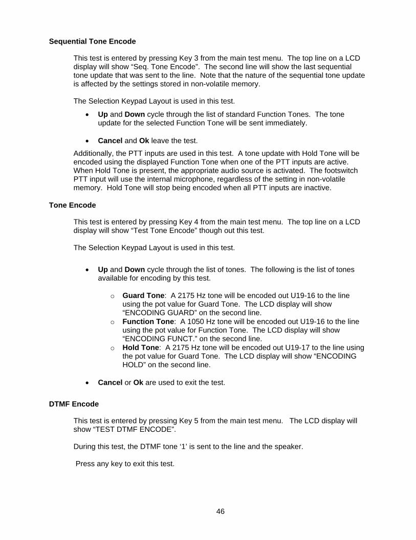
Sequential Tone Encode
This test is entered by pressing Key 3 from the main test menu. The top line on a LCD display will show “Seq. Tone Encode”. The second line will show the last sequential tone update that was sent to the line. Note that the nature of the sequential tone update is affected by the settings stored in non-volatile memory. The Selection Keypad Layout is used in this test.
• Up and Down cycle through the list of standard Function Tones. The tone update for the selected Function Tone will be sent immediately.
• Cancel and Ok leave the test.
Additionally, the PTT inputs are used in this test. A tone update with Hold Tone will be encoded using the displayed Function Tone when one of the PTT inputs are active. When Hold Tone is present, the appropriate audio source is activated. The footswitch PTT input will use the internal microphone, regardless of the setting in non-volatile memory. Hold Tone will stop being encoded when all PTT inputs are inactive.
Tone Encode
This test is entered by pressing Key 4 from the main test menu. The top line on a LCD display will show “Test Tone Encode” though out this test. The Selection Keypad Layout is used in this test.
• Up and Down cycle through the list of tones. The following is the list of tones available for encoding by this test.
o Guard Tone: A 2175 Hz tone will be encoded out U19-16 to the line
using the pot value for Guard Tone. The LCD display will show “ENCODING GUARD” on the second line.
o Function Tone: A 1050 Hz tone will be encoded out U19-16 to the line using the pot value for Function Tone. The LCD display will show “ENCODING FUNCT.” on the second line.
o Hold Tone: A 2175 Hz tone will be encoded out U19-17 to the line using the pot value for Guard Tone. The LCD display will show “ENCODING HOLD” on the second line.
• Cancel or Ok are used to exit the test.
DTMF Encode
This test is entered by pressing Key 5 from the main test menu. The LCD display will show “TEST DTMF ENCODE”. During this test, the DTMF tone ‘1’ is sent to the line and the speaker. Press any key to exit this test.
46
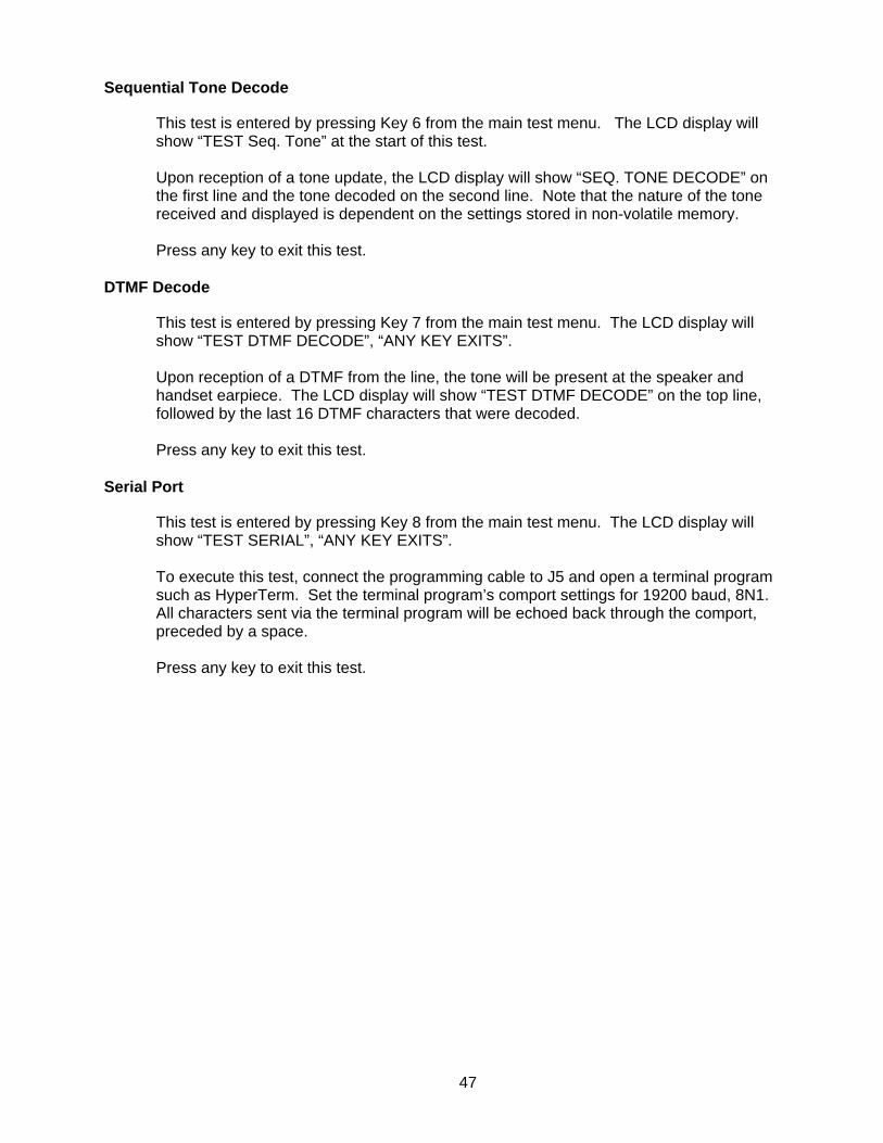
Sequential Tone Decode
This test is entered by pressing Key 6 from the main test menu. The LCD display will show “TEST Seq. Tone” at the start of this test. Upon reception of a tone update, the LCD display will show “SEQ. TONE DECODE” on the first line and the tone decoded on the second line. Note that the nature of the tone received and displayed is dependent on the settings stored in non-volatile memory. Press any key to exit this test.
DTMF Decode
This test is entered by pressing Key 7 from the main test menu. The LCD display will show “TEST DTMF DECODE”, “ANY KEY EXITS”. Upon reception of a DTMF from the line, the tone will be present at the speaker and handset earpiece. The LCD display will show “TEST DTMF DECODE” on the top line, followed by the last 16 DTMF characters that were decoded. Press any key to exit this test.
Serial Port
This test is entered by pressing Key 8 from the main test menu. The LCD display will show “TEST SERIAL”, “ANY KEY EXITS”. To execute this test, connect the programming cable to J5 and open a terminal program such as HyperTerm. Set the terminal program’s comport settings for 19200 baud, 8N1. All characters sent via the terminal program will be echoed back through the comport, preceded by a space. Press any key to exit this test.
47

Set Parameters
This test mode option is entered by pressing Key 9 from the main test menu. The LCD display will show “Set Parameters”, “APPLIED ON SAVE”. The keypad layout for this test is shown in the following table.
• 4 Wire Mode: This key adjusts the current setting for the wire mode. If the LED is on, 4 Wire Mode is on. If the LED is Off, 2 Wire Mode is on. Press this key to toggle this setting.
4 Wire Mode Speaker AGC Processor AGCUse Deskmic Full Duplex Cancel Save
• Speaker AGC: This key adjusts the current setting for Speaker AGC. If the LED
is on, the AGC is enabled for the speaker circuit. If the LED is off, AGC will be bypassed going to the speaker circuit. Press this key to toggle the Speaker AGC setting.
• Processor AGC: This key adjusts the current setting for the Audio Processor
Circuit AGC. If the LED is on, the AGC is enabled for the audio processors. If the LED is off, AGC will be bypassed going to the speaker circuit. Press this key to toggle the Processor AGC.
• Use Deskmic: This key adjusts the current setting for using the Deskmic. If the LED is on, the 24-67 expects a desk microphone to be connected to J11. If the LED is off, the 24-67 expects a handset to be connected to J11. Press this key to toggle using the Deskmic.
• Cancel: Press this key to abort this test mode option. Nothing will be written to non-volatile memory.
• Save: Press this key to save the settings displayed to non-volatile memory. The 24-67 will restart after the settings are saved.
Reset to Defaults
This test is entered by pressing Key 10 from the main test menu. The LCD display will show “DEFAULT PARAMETERS?” To reset the configuration values to their default settings, press “Ok” using the Selection Keypad Layout. The 24-67 will restart after the configuration values are written to non-volatile memory. To exit this test mode option without resetting the parameters to their default settings, press any key other that “Ok”.
48
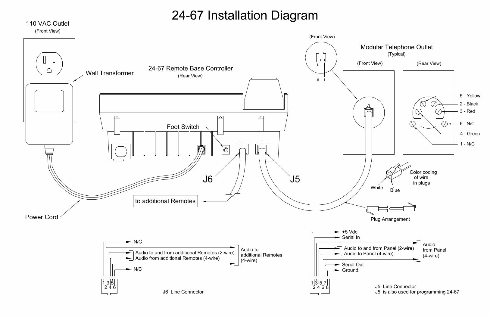
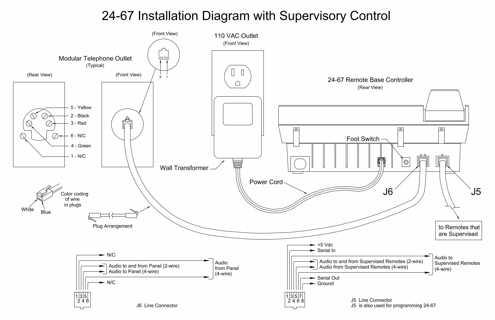
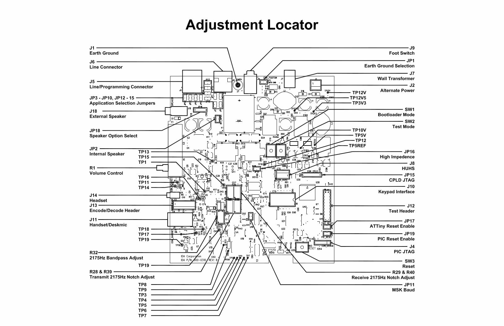
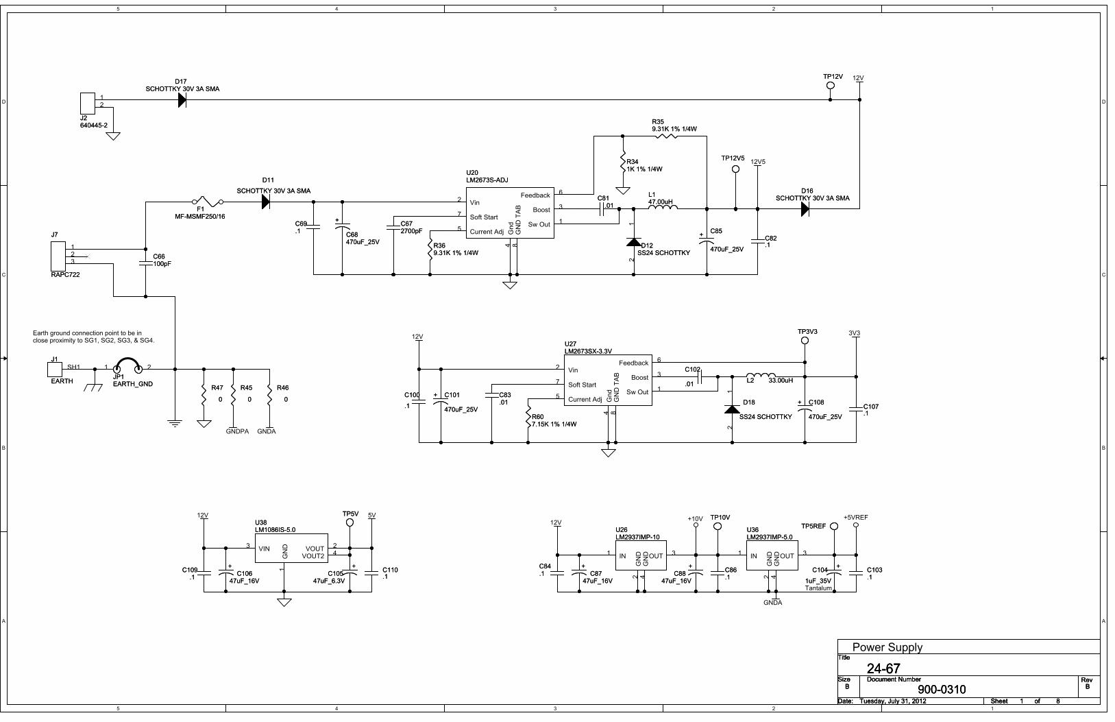
5
5
4
4
3
3
2
2
1
1
D D
C C
B B
A A
5V
12V5
12V
3V312V
12V+10V +5VREF
GNDA
GNDPA GNDA
12V
Title
Size Document Number Rev
Date: Sheet of
900-0310 B
24-67B
Tuesday, July 31, 2012 81
Title
Size Document Number Rev
Date: Sheet of
900-0310 B
24-67B
Tuesday, July 31, 2012 81
Title
Size Document Number Rev
Date: Sheet of
900-0310 B
24-67B
Tuesday, July 31, 2012 81
Power Supply
Tantalum
Earth ground connection point to be inclose proximity to SG1, SG2, SG3, & SG4.
D11
SCHOTTKY 30V 3A SMA
D11
SCHOTTKY 30V 3A SMA
+C85
470uF_25V
+C85
470uF_25V
+C87
47uF_16V
+C87
47uF_16V
SH1
J1
EARTH
J1
EARTH
+
C68470uF_25V
+
C68470uF_25V
L2 33.00uHL2 33.00uH
C69.1C69.1
+ C101
470uF_25V
+ C101
470uF_25V
21
D18
SS24 SCHOTTKY
D18
SS24 SCHOTTKY
C81.01
C81.01
+C104
1uF_35V
+C104
1uF_35V
C109.1
C109.1
R359.31K 1% 1/4WR359.31K 1% 1/4W
C100
.1
C100
.1
C83.01C83.01
D17SCHOTTKY 30V 3A SMA
D17SCHOTTKY 30V 3A SMA
C107.1C107.1
+C106
47uF_16V
+C106
47uF_16V
C82.1C82.1
C86.1C86.1
123
J7
RAPC722
J7
RAPC722
TP12VTP12V
Sw Out 1
Boost 3
Feedback 6
Gnd
4
Current Adj5
Soft Start7
Vin2
GND TAB
8
U27LM2673SX-3.3VU27LM2673SX-3.3V
D16SCHOTTKY 30V 3A SMA
D16SCHOTTKY 30V 3A SMA
R341K 1% 1/4WR341K 1% 1/4W
C66100pFC66100pF
12
J2640445-2J2640445-2
R45
0
R45
0
C672700pFC672700pF
+C88
47uF_16V
+C88
47uF_16V
C103.1C103.1
21
D12SS24 SCHOTTKYD12
SS24 SCHOTTKY
R47
0
R47
0
R607.15K 1% 1/4WR607.15K 1% 1/4W
IN1
GND
2
OUT 3
GND
4
U26LM2937IMP-10U26LM2937IMP-10
R46
0
R46
0
TP5REFTP5REF
TP3V3TP3V3
Sw Out 1
Boost 3
Feedback 6
Gnd
4
Current Adj5
Soft Start7
Vin2
GND TAB
8
U20LM2673S-ADJU20LM2673S-ADJ
GND
1
VOUT 2VIN3
VOUT2 4
U38LM1086IS-5.0U38LM1086IS-5.0
C84.1C84.1
C102
.01
C102
.01
IN1
GND
2
OUT 3
GND
4
U36LM2937IMP-5.0U36LM2937IMP-5.0
R369.31K 1% 1/4WR369.31K 1% 1/4W
1 2
JP1EARTH_GNDJP1EARTH_GND
TP12V5TP12V5
F1MF-MSMF250/16
F1MF-MSMF250/16
C110.1C110.1
TP10VTP10V
+ C108
470uF_25V
+ C108
470uF_25V
+C105
47uF_6.3V
+C105
47uF_6.3V
L147.00uHL147.00uH
TP5VTP5V
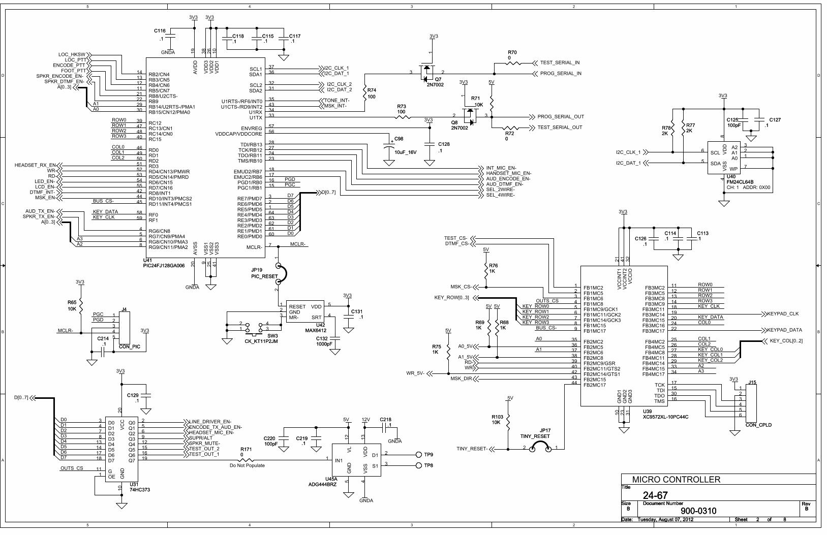
5
5
4
4
3
3
2
2
1
1
D D
C C
B B
A A
PGDPGC
PGDPGC
MCLR-
D7D6D5D4D3D2D1D0
A3A2
A1A0
BUS_CS-
D0D1D2
D4D5D6D7
D3
OUTS_CS
OUTS_CS
BUS_CS-COL0
COL1A0
A1
KEY_DATA
ROW0ROW1ROW2
KEY_ROW3
KEY_ROW0ROW3
KEY_COL2
KEY_CLK
KEY_COL1
COL2
KEY_ROW1KEY_ROW2
A2A3
KEY_COL0
KEY_DATAKEY_CLK
ROW0ROW1ROW2ROW3
COL0COL1COL2
MCLR-
3V3
3V3
3V3
3V3
GNDA
GNDA3V3
3V3
5V3V3
3V3
3V3
3V3
5V
5V5V
3V3
5V
5V
GNDA
GNDA
12V
5V
3V3
I2C_CLK_1
I2C_DAT_1
I2C_DAT_1I2C_CLK_1
TINY_RESET-
I2C_DAT_2I2C_CLK_2
LINE_DRIVER_EN-
RD-
TEST_CS-
WR-
SPKR_MUTE-
PROG_SERIAL_OUT
SUPR/ALT
DTMF_CS-
D[0..7]
TONE_INT-
DTMF_INT-
LOC_PTTLOC_HKSW
PROG_SERIAL_IN
TEST_SERIAL_IN
TEST_SERIAL_OUT
ENCODE_PTT
ENCODE_TX_AUD_EN-
A[0..3]
MSK_INT-
D[0..7]
MSK_CS-
RD-WR-
WR_5V-
A1_5V
A0_5V
KEYPAD_CLK
KEYPAD_DATA
A[0..3]
TEST_OUT_2TEST_OUT_1
LCD_EN-LED_EN-
FOOT_PTT
HEADSET_MIC_EN-
MSK_DIR
SPKR_ENCODE_EN-SPKR_DTMF_EN-
AUD_TX_EN-SPKR_TX_EN-
MSK_EN-
KEY_ROW[0..3]
KEY_COL[0..2]
SEL_4WIRE-SEL_2WIRE-AUD_DTMF_EN-AUD_ENCODE_EN-HANDSET_MIC_EN-INT_MIC_EN-
HEADSET_RX_EN-
Title
Size Document Number Rev
Date: Sheet of
900-0310 B
24-67B
Tuesday, August 07, 2012 82
Title
Size Document Number Rev
Date: Sheet of
900-0310 B
24-67B
Tuesday, August 07, 2012 82
Title
Size Document Number Rev
Date: Sheet of
900-0310 B
24-67B
Tuesday, August 07, 2012 82
MICRO CONTROLLER
CH: 1 ADDR: 0X00
Do Not Populate
R74
100
R74
100
R10310KR10310K
C1321000pFC1321000pF
C114.1C114.1
C218.1
C218.1
A0 1A1 2A2 3
SDA5
SCL6
VSS
4VDD
8
WP 7
U40FM24CL64BU40FM24CL64B
RE5/PMD5 1RE6/PMD6 2RE7/PMD7 3
RG6/CN84
RG7/CN9/PMA45
RG8/CN10/PMA36
MCLR- 7RG9/CN11/PMA28
VSS1
9
VDD1
10
RB5/CN711RB4/CN612RB3/CN513RB2/CN414
PGC1/RB1 15PGD1/RB0 16
EMUC2/RB6 17EMUD2/RB7 18
AVDD
19
AVSS
20
RB8/U2CTS-21
RB922
TMS/RB10 23
SDA1 36
U1RTS-/RF6/INT0 35
TDO/RB11 24
SCL2 32
SDA2 31
RB15/CN12/PMA030RB14/U2RTS-/PMA129
TDI/RB13 28
TCK/RB12 27
VDD2
26
VSS2
25
U1TX 33U1RX 34
SCL1 37
VDD3
38
RC1239
RC1540
VSS3
41
RD8/INT142
U1CTS-/RD9/INT2 43
RD10/INT3/PMCS244
RD11/INT4/PMCS145
RD046
RC13/CN147
RC14/CN048
RD149
RD250
RD351
RE4/PMD4 64
RE3/PMD3 63
RE2/PMD2 62
RE1/PMD1 61
RE0/PMD0 60
RF159RF058
ENVREG 57
VDDCAP/VDDCORE 56
RD7/CN1655RD6/CN1554RD5/CN14/PMRD53RD4/CN13/PMWR52
U41PIC24FJ128GA006U41PIC24FJ128GA006
FB1MC21
FB1MC52
FB1MC63
FB1MC84
FB1MC9/GCK15
FB1MC11/GCK26
FB1MC14/GCK37
FB1MC158
FB1MC179
GND1
10
FB3MC2 11
FB3MC5 12
FB3MC8 13
FB3MC9 14
TDI 15
TMS 16
TCK 17
FB3MC11 18
FB3MC14 19
FB3MC15 20
VCCINT1
21
FB3MC17 22
GND2
23
FB2MC536FB2MC235
FB3MC16 24
VCCIO
32
GND3
31
TDO 30
FB4MC14 29FB4MC11 28FB4MC8 27FB4MC5 26FB4MC2 25
FB4MC15 33
FB4MC17 34
FB2MC637
FB2MC838
FB2MC9/GSR39
FB2MC11/GTS240
VCCINT2
41
FB2MC14/GTS142
FB2MC1543
FB2MC1744
U39XC9572XL-10PC44CU39XC9572XL-10PC44C
12
JP17
TINY_RESET
JP17
TINY_RESET
R71
10K
R71
10K
C131.1
C131.1
R691KR691K
R1710R1710
D03
D14
D27
D38
D413
D514
D617
D718
OE1G11
Q0 2
Q1 5
Q2 6
Q3 9
Q4 12
Q5 15
Q6 16
Q7 19
VCC
20
GND
10 U31
74HC373U3174HC373
R772KR772K
3
1
2
Q82N7002Q82N7002
RESET1
GND2
MR-3 SRT 4
VDD 5
U42MAX6412
U42MAX6412
C117.1C117.1
12345
J4
CON_PIC
J4
CON_PIC
C219.1
C219.1
IN11
GND
5
VSS
4
S1 3
D1 2VL
12
VDD
13
U45AADG444BRZ
U45AADG444BRZ
C115.1C115.1
C214.1
C214.1
C113.1C113.1
12
JP19
PIC_RESET
JP19
PIC_RESET
R700R700
+C98
10uF_16V
+C98
10uF_16V
3
1
2
Q72N7002
Q72N7002
C125100pFC125100pF
C126.1
C126.1
R761KR761K
C129.1
C129.1
123456
J15
CON_CPLD
J15
CON_CPLD
R751KR751K
TP8TP8
C127.1
C127.1
R73100R73100
R681KR681K
C118.1C118.1
R782KR782KR72
0R720
C128
.1
C128
.1
C116
.1
C116
.1
TP9TP9
312 4
SW3CK_KT11P2JM
SW3CK_KT11P2JM
C220100pFC220100pF
R65
10K
R65
10K
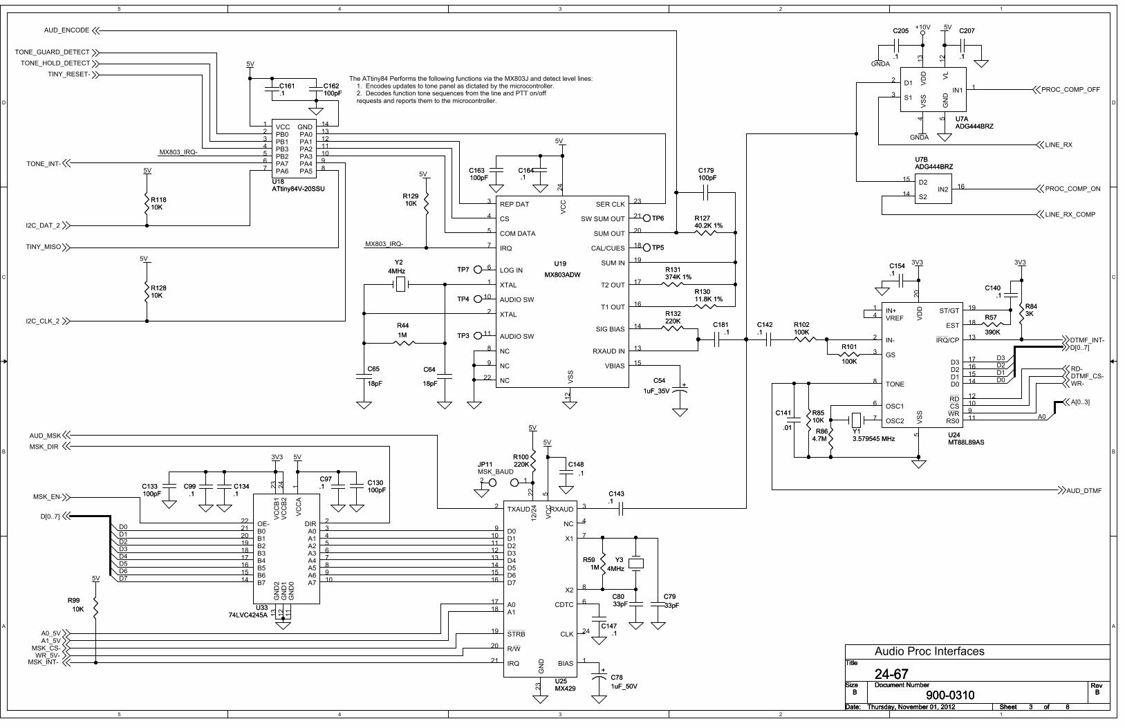
5
5
4
4
3
3
2
2
1
1
D D
C C
B B
A A
D0
D3D2D1
D7D6D5D4D3D2D1D0
MX803_IRQ-
MX803_IRQ-
A0
5V+10V
GNDA
GNDA
5V
5V
5V
5V
3V3 3V3
5V
5V
5V
5V
3V3 5V
AUD_ENCODE
TONE_HOLD_DETECT
TONE_GUARD_DETECT
I2C_CLK_2
I2C_DAT_2
TONE_INT-
TINY_RESET-
LINE_RX
LINE_RX_COMP
PROC_COMP_OFF
PROC_COMP_ON
TINY_MISO
AUD_DTMF
WR-DTMF_CS-RD-
D[0..7]
D[0..7]
AUD_MSK
MSK_CS-
MSK_INT-WR_5V-
A0_5VA1_5V
A[0..3]
DTMF_INT-
MSK_DIR
MSK_EN-
Title
Size Document Number Rev
Date: Sheet of
900-0310 B
24-67B
Thursday, November 01, 2012 83
Title
Size Document Number Rev
Date: Sheet of
900-0310 B
24-67B
Thursday, November 01, 2012 83
Title
Size Document Number Rev
Date: Sheet of
900-0310 B
24-67B
Thursday, November 01, 2012 83
The ATtiny84 Performs the following functions via the MX803J and detect level lines:1. Encodes updates to tone panel as dictated by the microcontroller.2. Decodes function tone sequences from the line and PTT on/offrequests and reports them to the microcontroller.
Audio Proc Interfaces
MSK_BAUD
C207
.1
C207
.1
R57
390K
R57
390K
TP6TP6
C142.1C142.1
IN2 16D215
S214
U7BADG444BRZU7BADG444BRZ
TP4TP4
TP7TP7
Y13.579545 MHzY13.579545 MHz
Y3
4MHz
Y3
4MHz
VCC
5
A017
A118
STRB19
R/W20
IRQ21
12/24
22
CDTC 6
X1 7
X2 8
RXAUD 3
NC 4
BIAS 1
D09
D110
D211
D312
D413
D514
D615
D716
TXAUD2
CLK 24
GND
23 U25
MX429U25MX429
C141
.01
C141
.01
VCCA
1
DIR 2
A0 3
A1 4
A2 5
A3 6
A4 7
A5 8
A6 9
A7 10
GND0
11
GND1
12
GND2
13
B714B615B516B417B318B219B120B021OE-22
VCCB1
23
VCCB2
24
U3374LVC4245A
U3374LVC4245A
R864.7MR86
4.7M
C8033pFC8033pF
IN1 1
GND
5
VSS
4
S13
D12 VL
12
VDD
13
U7AADG444BRZU7AADG444BRZ
C134.1C134.1
R591M
R591M
R843KR843K
C133100pFC133100pF
VSS
12
AUDIO SW11
AUDIO SW10
NC9
NC8
IRQ7
LOG IN6
COM DATA5
CS4
REP DAT3
XTAL2
XTAL1
SER CLK 23
NC22
SW SUM OUT 21
SUM OUT 20
SUM IN 19
CAL/CUES 18
T2 OUT 17
T1 OUT 16
VBIAS 15
SIG BIAS 14
RXAUD IN 13
VCC
24
U19
MX803ADW
U19
MX803ADW
+C54
1uF_35V+
C54
1uF_35V
C79
33pF
C79
33pF
+C78
1uF_50V
+C78
1uF_50V
12
JP11JP11R100220KR100220K
C154.1C154.1
C147.1
C147.1
R12740.2K 1%R12740.2K 1%
R8510KR8510K
Y2
4MHz
Y2
4MHz
C162100pFC162100pF
C130100pFC130100pF
C143.1C143.1
TP3TP3
C179100pFC179100pF
R12810KR12810K
R44
1M
R44
1M
R99
10K
R99
10K
C163100pFC163100pF
VCC1
PB02
PB13
PB25PB34
PA76
PA67 PA5 8PA4 9PA3 10PA2 11PA1 12PA0 13GND 14
U18ATtiny84V-20SSUU18ATtiny84V-20SSU
C140.1
C140.1
R101
100K
R101
100K
R131374K 1%R131374K 1%
C65
18pF
C65
18pF
C64
18pF
C64
18pF
R11810KR11810K
C161.1C161.1
R132220KR132220K
R13011.8K 1%R13011.8K 1%
C164.1C164.1
R102100KR102100K
TP5TP5
IN+1
IN-2
GS3
OSC16
OSC27
VREF4
VSS
5
D3 17
D2 16
D1 15
D0 14
EST 18
ST/GT 19
VDD
20
IRQ/CP 13
RD 12
RS0 11
TONE8
WR 9CS 10
U24MT88L89ASU24MT88L89AS
C181.1
C181.1
R12910KR12910K
C148
.1
C148
.1
C99.1
C99.1
C97.1C97.1
C205
.1
C205
.1

5
5
4
4
3
3
2
2
1
1
D D
C C
B B
A A
+10V
+10V
+10V
+5VREF
+5VREF
+5VREF
+5VREF
GNDA
GNDA
GNDA
GNDA
GNDA
3V3
3V3
GNDA
GNDA
GNDA
GNDA
+10V
+5VREF
GNDA
+10V
GNDA
5V
GNDA
5V
LINE_RX
TONE_GUARD_DETECT
TONE_HOLD_DETECT
I2C_CLK_1
I2C_DAT_1
PROC_COMP_OFF
PROC_COMP_ON
Title
Size Document Number Rev
Date: Sheet of
900-0310 B
24-67B
4 8Tuesday, November 13, 2012
Title
Size Document Number Rev
Date: Sheet of
900-0310 B
24-67B
4 8Tuesday, November 13, 2012
Title
Size Document Number Rev
Date: Sheet of
900-0310 B
24-67B
4 8Tuesday, November 13, 2012
2175HZBANDPASSADJUST
2175 Detector
CH:1 ADDR: 0X01
2175 DETECT
+
C491uF_35V +
C491uF_35V
R121
3.9K
R121
3.9K
3
21
411
+
-
U6A
TL064ID
+
-
U6A
TL064ID
C174
100pF
C174
100pF
1
2
3
D9
MMBD4148SE
D9
MMBD4148SE
VDD
7
VL
10
GND
8
VSS
18
A12
W13
B11
SHDN 15
SDI/SDA 11
CLK/SCL 12
DIS 9CS/AD013
RES/AD114
NC/O217
SDO/O116
U13AAD5263BRUZ50U13AAD5263BRUZ50
R126
3.0K
R126
3.0K
R120
10K
R120
10K
R117
7.15K 1%
R117
7.15K 1%
C52
.1
C52
.1
C171
.1
C171
.1
C180
.1
C180
.1
10
98
+
-
U12CTL064ID
+
-
U12CTL064ID
R1503.9KR1503.9K
5
67
+
-
U12BTL064ID
+
-
U12BTL064ID
R1143.9KR1143.9K
TP2TP HOOPTP2TP HOOP
R124
750K 1%
R124
750K 1%
5
67
+
-
U11BLM2903M
+
-
U11BLM2903M
C51
.01 ULTRA
C51
.01 ULTRA
C63
.1
C63
.1
C201
.1
C201
.1
C175
.1
C175
.1
R30
22K
R30
22K
R133
100
R0603
R133
100
R0603
C34
.1
C34
.1
3
21
411
+
-
U12ATL064ID
+
-
U12ATL064ID
C36
.22uF
C36
.22uF
R123
6.8K
R123
6.8K
R119
7.15K 1%
R119
7.15K 1%
R24
4.7K
R24
4.7K12
1314
+
-
U12D
TL064ID
+
-
U12D
TL064ID
R122
7.15K 1%
R122
7.15K 1%
R115
2.2K
R115
2.2K
C50.01 ULTRA
C50.01 ULTRA
C172.47uFC172.47uF
R155
10K
R155
10K
R15710KR15710K
1
2
3
D10
MMBD4148SE
D10
MMBD4148SE
R32
2K 22T
14T SMT
R32
2K 22T
14T SMT
C202.1C202.1
C204
100pF
C204
100pF
C203
.1
C203
.1
C197
.1
C197
.1
3
21
84
+
-
U11A
LM2903M
+
-
U11A
LM2903M
C173
.1
C173
.1
R125
220K
R125
220K
C176
.22uF
C176
.22uF
R43
470K
R43
470K
C177.1C177.1
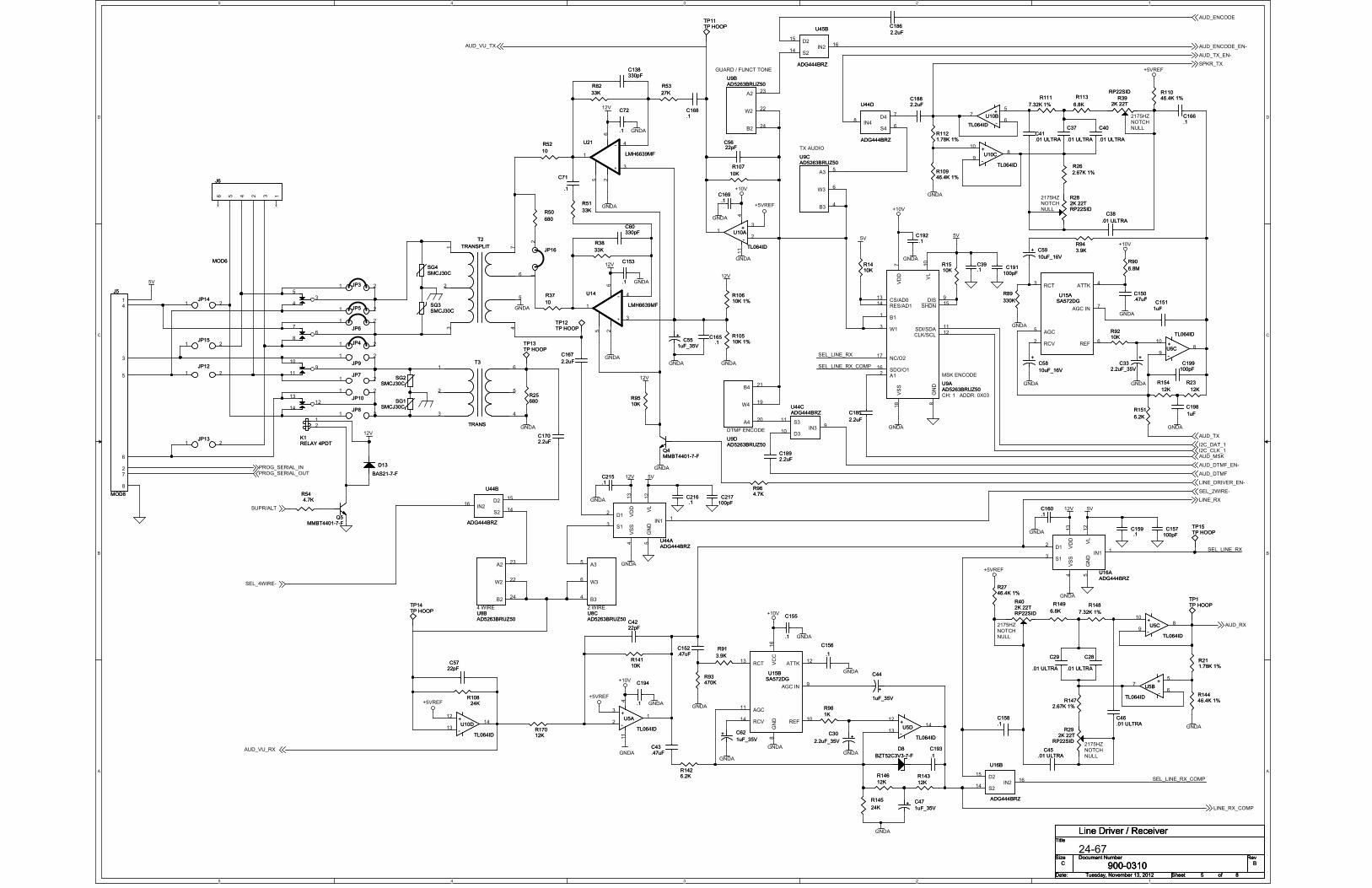
5
5
4
4
3
3
2
2
1
1
D D
C C
B B
A A
SEL_LINE_RX
SEL_LINE_RX_COMP
SEL_LINE_RX
SEL_LINE_RX_COMP
+5VREF
+5VREF
+10V
GNDA
GNDA
GNDA
GNDA
+5VREF
+5VREF
GNDA
+10V
GNDA
GNDA
GNDA
GNDA
GNDA
GNDA
GNDA
GNDA
GNDA
+10V
GNDA
GNDA
GNDA
12V
12V
GNDA
GNDA12V
GNDA
GNDA
GNDA
12V
5V
GNDA
GNDA
12V
5V
12V
+10V
GNDA
5V
GNDA
+5VREF
5V
GNDA
GNDA
GNDA
+10V
GNDA
GNDA
5V
GNDA
GNDA
12VLINE_DRIVER_EN-
LINE_RX
AUD_TX
LINE_RX_COMP
AUD_RX
AUD_ENCODE
AUD_DTMFPROG_SERIAL_OUTPROG_SERIAL_IN
SUPR/ALT
AUD_VU_RX
AUD_VU_TX
AUD_MSK
I2C_DAT_1I2C_CLK_1
SPKR_TX
SEL_2WIRE-
SEL_4WIRE-
AUD_DTMF_EN-
AUD_TX_EN-
AUD_ENCODE_EN-
Title
Size Document Number Rev
Date: Sheet of
900-0310 B
Line Driver / Receiver
C
5 8Tuesday, November 13, 2012
Title
Size Document Number Rev
Date: Sheet of
900-0310 B
Line Driver / Receiver
C
5 8Tuesday, November 13, 2012
Title
Size Document Number Rev
Date: Sheet of
900-0310 B
Line Driver / Receiver
C
5 8Tuesday, November 13, 2012
2175HZNOTCHNULL
2175HZNOTCHNULL
2175HZNOTCHNULL
24-67
2175HZNOTCHNULL
CH: 1 ADDR: 0X03
GUARD / FUNCT TONE
TX AUDIO
MSK ENCODE
DTMF ENCODE
4 WIRE 2 WIRE
R113
6.8K
R113
6.8K
C157100pFC157
100pF
R10610K 1%R10610K 1%
R14446.4K 1%R14446.4K 1%
C150.47uFC150.47uF
R23
12K
R23
12K
R51
33K
R51
33K
R9510KR9510K
TP13TP HOOPTP13TP HOOP
R11046.4K 1%R11046.4K 1%
10
98
+
-
U5C
TL064ID
+
-
U5C
TL064ID
C186
2.2uF
C186
2.2uF
C166.1C166.1
R149
6.8K
R149
6.8KTP14TP HOOPTP14TP HOOP
R82
33K
R82
33K
C43.47uFC43.47uF
R90
6.8M
R90
6.8M
R10510K 1%R10510K 1%
C71
.1
C71
.1
R544.7KR544.7K
+C30
2.2uF_35V+
C30
2.2uF_35V
R148
7.32K 1%
R148
7.32K 1%
C1892.2uFC1892.2uF
5
67
+
-
U10B
TL064ID
+
-
U10B
TL064ID
C45.01 ULTRA
C45.01 ULTRA
R50
680
R50
680
R2746.4K 1%R2746.4K 1%
1 2JP7JP7
R89
330K
R89
330K
R392K 22T
RP22SID
R392K 22T
RP22SID
1 2JP5JP5
C217100pFC217
100pF
R145
24K
R145
24K
RCT13
RCV14
ATTK12
AGC IN9
REF10
AGC11
VCC
16
GND
8
U15BSA572DGU15BSA572DG
R111
7.32K 1%
R111
7.32K 1%
SG2SMCJ30C
SG2SMCJ30C
A35
W36
B34
U8CAD5263BRUZ50U8CAD5263BRUZ50
R1426.2KR1426.2K
R93470KR93470K
C156
.1
C156
.1
R1472.67K 1%
R1472.67K 1%
+ C59
10uF_16V
+ C59
10uF_16V
IN216
D215
S214
U44B
ADG444BRZ
U44B
ADG444BRZ
134 256
J6
MOD6
J6
MOD6
TP11TP HOOPTP11TP HOOP
R26
2.67K 1%
R26
2.67K 1%
R402K 22TRP22SID
R402K 22TRP22SID
+
C44
1uF_35V
+
C44
1uF_35V
C5622pFC5622pF
A223
W222
B224
U8BAD5263BRUZ50U8BAD5263BRUZ50
C1702.2uFC1702.2uF
35
4
67
8
911
10
1213
14
12
K1RELAY 4PDTK1RELAY 4PDT
A223
W222
B224
U9BAD5263BRUZ50U9BAD5263BRUZ50
3
21
411
+
-
U5A
TL064ID
+
-
U5A
TL064ID
TP15TP HOOPTP15TP HOOP
C152.47uFC152.47uF
C72
.1
C72
.1
13
2
4
5
6
7
T2
TRANSPLIT
T2
TRANSPLIT
1 2JP3JP3
C159.1C159.1
1 2JP4JP4
C158.1C158.1
C5722pFC5722pF
R91
3.9K
R91
3.9K
+ C47
1uF_35V+ C47
1uF_35V
R1410KR1410K
R17012KR17012K
C151
1uF
C151
1uF
IN216
D215
S214
U16B
ADG444BRZ
U16B
ADG444BRZ
A420
W419
B421
U9DAD5263BRUZ50U9DAD5263BRUZ50
1
3
4
625
-
+
U21
LMH6639MF
-
+
U21
LMH6639MF
R211.78K 1%R211.78K 1%
1 2JP14JP14
C4222pFC4222pF
IN216
D215
S214
U45B
ADG444BRZ
U45B
ADG444BRZ
R38
33K
R38
33K
C168.1C168.1
1 2
JP12JP12
RCT3
RCV2
ATTK4
AGC IN7
REF6
AGC5
U15ASA572DGU15ASA572DG
R292K 22T
RP22SID
R292K 22T
RP22SID
VDD
7
VL
10
GND
8
VSS
18
A12
W13
B11
SHDN15
SDI/SDA11
CLK/SCL12
DIS9
CS/AD013
RES/AD114
NC/O217
SDO/O116
U9AAD5263BRUZ50U9AAD5263BRUZ50
+ C62
1uF_35V+ C62
1uF_35V
R143
12K
R143
12K
R282K 22TRP22SID
R282K 22TRP22SID
R52
10
R52
10
+C55
1uF_35V
+C55
1uF_35V
10
98
+
-
U10C
TL064ID
+
-
U10C
TL064ID
IN11
GND
5
VSS
4
S13
D12 V
L12
VDD
13
U16AADG444BRZU16AADG444BRZ
3
21
411
+
-
U10A
TL064ID
+
-
U10A
TL064ID
R53
27K
R53
27K
C46.01 ULTRAC46.01 ULTRA
1 2JP8JP8
10
98
+
-
U6C
TL064ID
+
-
U6C
TL064IDC165
.1C165
.1
R146
12K
R146
12K
C38
.01 ULTRA
C38
.01 ULTRA
12
1314
+
-
U5D
TL064ID
+
-
U5D
TL064ID
D8
BZT52C3V3-7-F
D8
BZT52C3V3-7-F
1 2
JP9JP9
C169.1
C169.1
C191100pFC191
100pF
IN48
D47
S46
U44D
ADG444BRZ
U44D
ADG444BRZ
SG3SMCJ30CSG3SMCJ30C
TP1TP HOOPTP1TP HOOP
Q5MMBT4401-7-F
Q5MMBT4401-7-F
C194
.1
C194
.1
R9210KR9210K
C193
.1
C193
.1
+C58
10uF_16V
+C58
10uF_16V
C160.1C160.1
5
67
+
-
U5B
TL064ID
+
-
U5B
TL064ID
C216.1C216.1
C60330pFC60330pF
R1510KR1510K
C1882.2uFC1882.2uF
R14110KR14110K
R98
1K
R98
1K
R1121.78K 1%R1121.78K 1%
SG1SMCJ30C
SG1SMCJ30C
C138330pFC138330pF
R154
12K
R154
12K
3
2
1
4
5
6T3
TRANS
T3
TRANS
C198
1uF
C198
1uF
C29
.01 ULTRA
C29
.01 ULTRA
C39.1C39.1
1
3
4
625
-
+
U14
LMH6639MF
-
+
U14
LMH6639MF
C37
.01 ULTRA
C37
.01 ULTRA
C215.1C215.1
R964.7KR964.7K
R10946.4K 1%R10946.4K 1%
12
JP16JP16
C153
.1
C153
.1
1
2
3
4
5
6
7
8
J5
MOD8
J5
MOD8
IN39
D310
S311
U44CADG444BRZU44CADG444BRZ
SG4SMCJ30CSG4SMCJ30C
R37
10
R37
10
C185
2.2uF
C185
2.2uF
R25680R25680
+C33
2.2uF_35V
+C33
2.2uF_35V
TP12TP HOOPTP12TP HOOP
1 2
JP6JP6
R151
6.2K
R151
6.2K
Q4MMBT4401-7-FQ4MMBT4401-7-F
C41.01 ULTRAC41.01 ULTRA
12
1314
+
-
U10D
TL064ID
+
-
U10D
TL064ID
C28
.01 ULTRA
C28
.01 ULTRA
D13
BAS21-7-F
D13
BAS21-7-F
1 2JP15JP15
C199100pFC199100pF
A35
W36
B34
U9CAD5263BRUZ50U9CAD5263BRUZ50
C192.1
C192.1
R94
3.9K
R94
3.9K
C155
.1
C155
.1
C167
2.2uF
C167
2.2uF
R107
10K
R107
10K
IN11
GND
5
VSS
4
S13
D12 V
L12
VDD
13
U44AADG444BRZU44AADG444BRZ
R10824K
R10824K
C40
.01 ULTRA
C40
.01 ULTRA
1 2JP13JP13
1 2
JP10JP10

5
5
4
4
3
3
2
2
1
1
D D
C C
B B
A A
D3D2
D0D1
D0
D1
3V3
3V3
3V3
3V3
3V3 12V512V 5V +10V +5VREF
GNDA
5V3V3
3V3
3V3
RD-
WR-
TEST_CS-
D[0..7]
TINY_RESET-
TINY_MISO
I2C_CLK_2
I2C_DAT_2
TEST_SERIAL_OUT
TEST_SERIAL_IN
TEST_OUT_1
TEST_OUT_2
Title
Size Document Number Rev
Date: Sheet of
900-0310 B
24-67B
6 8Monday, August 06, 2012
Title
Size Document Number Rev
Date: Sheet of
900-0310 B
24-67B
6 8Monday, August 06, 2012
Title
Size Document Number Rev
Date: Sheet of
900-0310 B
24-67B
6 8Monday, August 06, 2012
Test
C119.1C119.1
41
2
35
U29
SN74AHC1G02DBVR
U29
SN74AHC1G02DBVR
2OE71OE1
1A 2
2A 5
VCC
8
1Y6
2Y3
GND
4
U28
SN74LVC2G240DCTR
U28
SN74LVC2G240DCTR
R87330R87330
C146
.1
C146
.1
C120.1C120.1
C124.1C124.1
3 124
SW1
CK_KT11P2JM
SW1
CK_KT11P2JM
B1 1
E 2
B2 3C24
C15
U43UMG2N
U43UMG2N
C111100pFC111
100pF
C122.1C122.1
R8010KR8010K
CLK1
Q 4
VCC
5
D3
GND
2CLR6
U34
SN74LVC1G175DBVT
U34
SN74LVC1G175DBVT
R6210KR6210K
2OE71OE1
1A 2
2A 5
VCC
8
1Y6
2Y3
GND
4
U30
SN74LVC2G240DCTR
U30
SN74LVC2G240DCTR
2A3 2Y 4
U32BSN74LVC2G34DBVRU32BSN74LVC2G34DBVR
3 124
SW2
CK_KT11P2JM
SW2
CK_KT11P2JM
C144.1C144.1
C136.1C136.1
1 23 45 67 89 1011 1213 141517
1618
19 20
J12
CON2X10/100
J12
CON2X10/100
C121100pFC121
100pF
C145100pFC145
100pF
C135100pFC135
100pF
D15D15
R7910KR7910K
C123100pFC123100pF
Vcc
5GND
2
1A1 1Y 6
U32ASN74LVC2G34DBVRU32ASN74LVC2G34DBVR
41
2
35
U37
SN74AHC1G32DBVR
U37
SN74AHC1G32DBVR
CLK1
Q 4
VCC
5
D3
GND
2
CLR6
U35
SN74LVC1G175DBVT
U35
SN74LVC1G175DBVT
D14D14
R9710KR9710K
R104330R104330
C112100pFC112100pF
R6110KR6110K
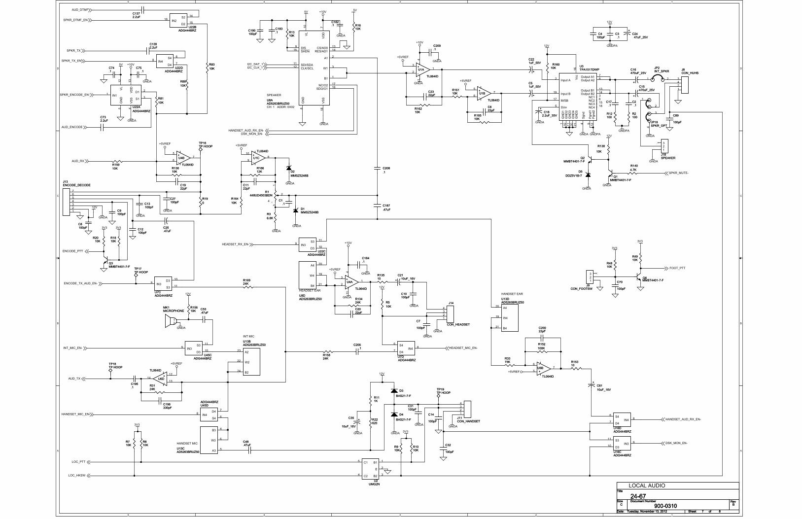
5
5
4
4
3
3
2
2
1
1
D D
C C
B B
A A
GNDA
+5VREF
GNDPA
GNDA
GNDA
GNDPA
GNDA GNDA
12V
GNDA12V
GNDAGNDA
12V
GNDPA
GNDA
+5VREF
+10V
GNDA
GNDA+5VREF
GNDA
+5VREF
GNDA
GNDA
12V
12V
GNDA
12V
GNDA
3V3 3V3
+5VREF
3V3
3V3
GNDA
GNDA
GNDA
GNDA
+5VREF
+10V
GNDA
12V
3V3
GNDA
3V3
GNDA
+5VREF
GNDA
+10V
GNDA
5V
GNDA
+10V
GNDA
5V
GNDA
5V
AUD_TX
LOC_HKSW
LOC_PTT
AUD_RX
SPKR_MUTE-
ENCODE_TX_AUD_EN-
ENCODE_PTT
HEADSET_MIC_EN-
FOOT_PTT
HANDSET_AUD_RX_EN-
DSK_MON_EN-
AUD_ENCODE
AUD_DTMF
SPKR_TX_EN-
SPKR_ENCODE_EN-
SPKR_DTMF_EN-
SPKR_TX
I2C_CLK_1I2C_DAT_1
DSK_MON_EN-HANDSET_AUD_RX_EN-
HEADSET_RX_EN-
INT_MIC_EN-
HANDSET_MIC_EN-
Title
Size Document Number Rev
Date: Sheet of
900-0310 B
24-67C
Tuesday, November 13, 2012 87
Title
Size Document Number Rev
Date: Sheet of
900-0310 B
24-67C
Tuesday, November 13, 2012 87
Title
Size Document Number Rev
Date: Sheet of
900-0310 B
24-67C
Tuesday, November 13, 2012 87
LOCAL AUDIO
INT MIC
CH: 1 ADDR: 0X02
SPEAKER
HEADSET EARHANDSET EAR
HANDSET MIC
+
C16470uF_25V
+
C16470uF_25V
C70
100pF
C70
100pF
C196330pFC196330pF
IN39
D310
S311
U45CADG444BRZ
U45CADG444BRZ
R111KR111K
12
1314
+
-
U6D
TL064ID
+
-
U6D
TL064ID
TP17TP HOOPTP17TP HOOP
C12100pFC12100pF
A420
W419
B421
U8DAD5263BRUZ50U8DAD5263BRUZ50
C1122pFC1122pF
D4
BAS21-7-F
D4
BAS21-7-F
+
C51uF_50V
+
C51uF_50V
R22620R22620
R164
10K
R164
10K
R3124KR3124K
1234567
J13ENCODE_DECODEJ13ENCODE_DECODE
C25.47uFC25.47uF
A223
W222
B224
U13BAD5263BRUZ50U13BAD5263BRUZ50
C190100pFC190100pF
R16510KR16510K
123
J18SPEAKERJ18SPEAKER
+
C221uF_50V
+
C221uF_50V
C187
.47uF
C187
.47uF
R140
4.7K
R140
4.7K
C209.1C209.1
123
J9CON_FOOTSW
J9CON_FOOTSW
R3375KR3375K
+
C15470uF_25V
+
C15470uF_25V
R910KR910K
C17.1
C17.1
C206.1
C206.1
C20022pFC20022pF
C10100pFC10100pF
C1392.2uFC1392.2uF
IN39
D310
S311
U7CADG444BRZU7CADG444BRZ
13
2
4
R1448UD4503BDN
R1448UD4503BDN
R12100R12100
C53.47uFC53.47uF
R138
10K
R138
10K
C732.2uFC732.2uF
R81
10K
R81
10K
R810KR810K
IN39
D310
S311
U22CADG444BRZ
U22CADG444BRZ
3
21
411
+
-
U4A
TL064ID
+
-
U4A
TL064ID
R16110KR16110K
IN48
D47
S46
U16DADG444BRZU16DADG444BRZ
R16612KR16612K
IN216
D215
S214
U22BADG444BRZ
U22BADG444BRZ
C8100pFC8100pF
C32
100pF
C32
100pF
IN48
D47
S46
U7DADG444BRZU7DADG444BRZ
5
67
+
-
U6B
TL064ID
+
-
U6B
TL064ID
R16210KR16210K
R4910KR4910K
1234
J11CON_HANDSETJ11CON_HANDSET
C2022pFC2022pF
GND1
1
GND2
10
GND3
11
GND4
20
Pgnd1
9
Pgnd2
12
Vcc
16
Output A17
Output A28
Output B113
Output B214
Input A2
Input B19
Sgnd
4
SVrr5
M/SB17
GND5
21
NC13
NC26
NC315
NC418
U3TPA1517DWPU3TPA1517DWP
R4810KR4810K
+C2447uF_25V
+C2447uF_25V
C4100pFC4
100pF
D2
MMSZ5248B
D2
MMSZ5248B
R19
0
R19
0
C1922pFC1922pF
A35
W36
B34
U13CAD5263BRUZ50U13CAD5263BRUZ50
R83
10K
R83
10KC75.1
C75.1
C89
100pF
C89
100pF
R15310R15310
TP16TP HOOPTP16TP HOOP
C3.1
C3.1
R1810KR1810K
IN39
D310
S311
U16CADG444BRZU16CADG444BRZ
TP19TP HOOPTP19TP HOOP
1 2
JP2INT_SPKRJP2INT_SPKR
C9100pFC9100pF
B11
E2
B23
C24
C15
U2UMG2N
U2UMG2N
C14
100pF
C14
100pF
IN48
D47
S46
U22DADG444BRZ
U22DADG444BRZ
IN48
D47
S46
U45DADG444BRZU45DADG444BRZ
+C18
2.2uF_35V
+C18
2.2uF_35V
1234
J14
CON_HEADSET
J14
CON_HEADSET
R16010KR160
10K
R1610KR1610K
C13100pFC13100pF
C31100pFC31100pF
12
34
J8CON_HUHSJ8CON_HUHS
1
2
3
4
JP18SPKR_OPTJP18SPKR_OPT
5
67
+
-
U4B
TL064ID
+
-
U4B
TL064ID
A420
W419
B421
U13DAD5263BRUZ50U13DAD5263BRUZ50
IN11
GND
5
VSS
4
S13
D12V
L12
VDD
13
U22A
ADG444BRZ
U22A
ADG444BRZ
+
C2110uF_16V+
C2110uF_16V
5
67
+
-
U1B
TL064ID
+
-
U1B
TL064ID
R2010K
R2010K
C2.1
C2.1
Q3MMBT4401-7-FQ3MMBT4401-7-F
Q6MMBT4401-7-FQ6MMBT4401-7-F
C208
.1
C208
.1
R159
10K
R159
10K
TP18TP HOOPTP18TP HOOP
R2100R2100
C622pFC622pF
R16924KR16924K
R710KR710K
R13610KR13610K
3
21
411
+
-
U1A
TL064ID
+
-
U1A
TL064ID
Q1MMBT4401-7-F
Q1MMBT4401-7-F
C48.47uFC48.47uF
D1MMSZ5248BD1MMSZ5248B
Q2MMBT4401-7-F
Q2MMBT4401-7-F
C195.1C195.1
12
MK1MICROPHONEMK1MICROPHONE
C7
100pF
C7
100pF
VDD
7
VL
10
GND
8
VSS
18
A12
W13
B11
SHDN15
SDI/SDA11
CLK/SCL12
DIS9
CS/AD013
RES/AD114
NC/O217
SDO/O116
U8AAD5263BRUZ50U8AAD5263BRUZ50
R15610KR15610K
C1.1
C1.1
R1310KR1310K
R88
10K
R88
10K
R3
6.8K
R3
6.8K
R13424KR13424K
+C61
10uF_16V
+C61
10uF_16V
C2322pFC2322pF
C74.1C74.1
C183.1C183.1
D5
DDZ5V1B-7
D5
DDZ5V1B-7
R13510R13510
R152
100K
R152
100K
R5
10K
R5
10K
C182.1C182.1
R1010KR1010K
C1372.2uFC1372.2uF
D3
BAS21-7-F
D3
BAS21-7-F
C27100pFC27100pF
10
98
+
-
U1C
TL064ID
+
-
U1C
TL064ID
C184.1C184.1
+C35
10uF_16V
+C35
10uF_16V
R15824KR15824K
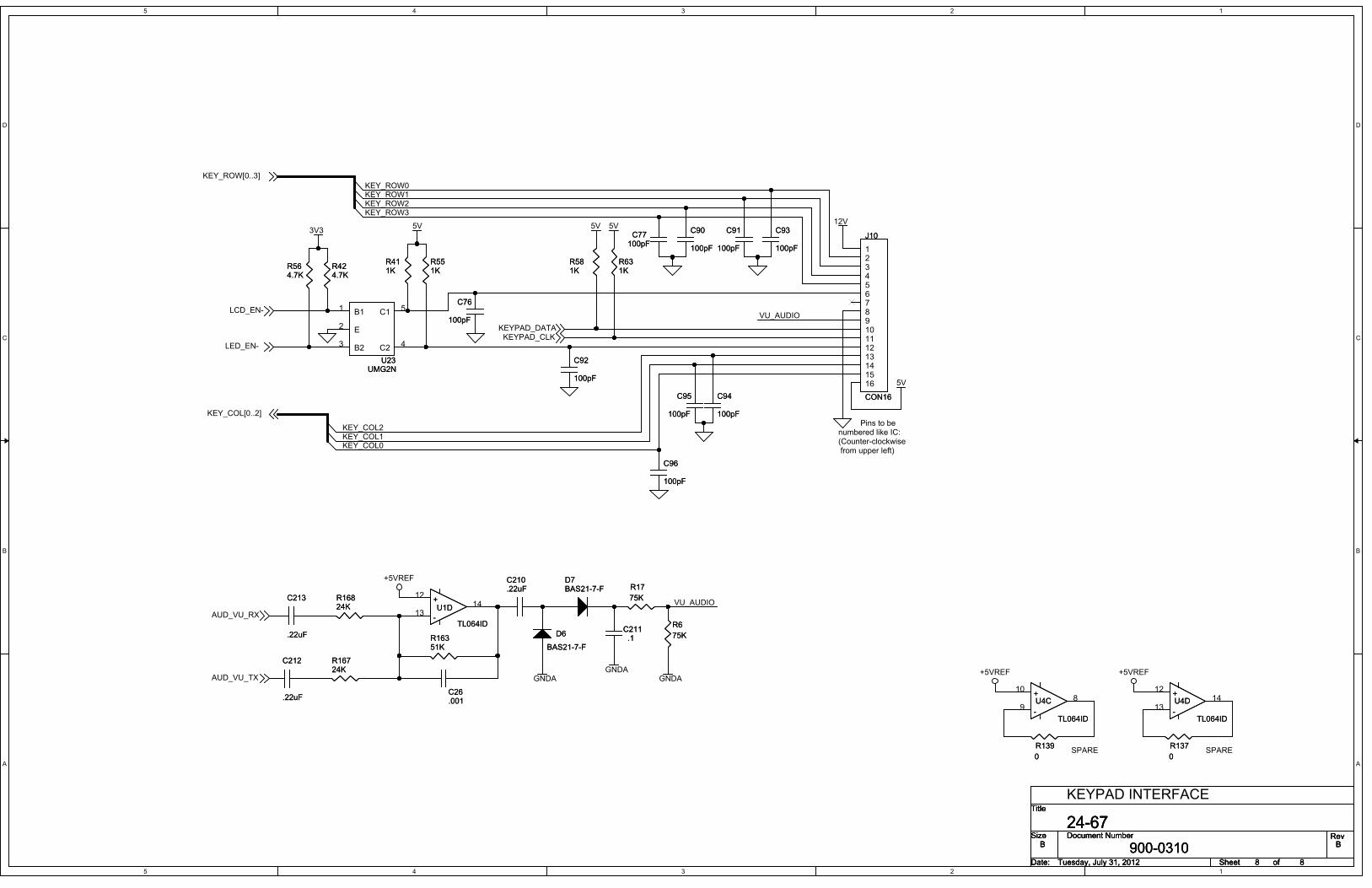
5
5
4
4
3
3
2
2
1
1
D D
C C
B B
A A
KEY_COL2KEY_COL1KEY_COL0
VU_AUDIO
VU_AUDIO
KEY_ROW0KEY_ROW1KEY_ROW2KEY_ROW3
12V
+5VREF
5V
3V3
GNDAGNDAGNDA
5V
+5VREF +5VREF
5V 5V
AUD_VU_TX
LCD_EN-
LED_EN-
AUD_VU_RX
KEYPAD_DATAKEYPAD_CLK
KEY_COL[0..2]
KEY_ROW[0..3]
Title
Size Document Number Rev
Date: Sheet of
900-0310 B
24-67B
Tuesday, July 31, 2012 88
Title
Size Document Number Rev
Date: Sheet of
900-0310 B
24-67B
Tuesday, July 31, 2012 88
Title
Size Document Number Rev
Date: Sheet of
900-0310 B
24-67B
Tuesday, July 31, 2012 88
Pins to be numbered like IC:(Counter-clockwise from upper left)
KEYPAD INTERFACE
SPARE SPARE
C93
100pF
C93
100pF
R16824KR16824K
10
98
+
-
U4C
TL064ID
+
-
U4C
TL064ID
C212
.22uF
C212
.22uF
D6
BAS21-7-F
D6
BAS21-7-F
R137
0
R137
0
B11
E2
B23 C2 4
C1 5
U23UMG2N
U23UMG2N
R16351KR16351K
C76
100pF
C76
100pF
R17
75K
R17
75K
C211.1
C211.1
R551KR551K
D7BAS21-7-FD7BAS21-7-F
R631KR631K
12345678910111213141516
J10
CON16
J10
CON16
C96
100pF
C96
100pF
R6
75K
R6
75K
C77100pFC77
100pF
R564.7KR564.7K
12
1314
+
-
U1D
TL064ID
+
-
U1D
TL064ID
R139
0
R139
0
R16724KR16724K
C92
100pF
C92
100pF
C91
100pF
C91
100pF
R411KR411K
R581KR581K
C210.22uFC210.22uF
12
1314
+
-
U4D
TL064ID
+
-
U4D
TL064ID
C94
100pF
C94
100pF
C95
100pF
C95
100pF
C26.001C26.001
C90
100pF
C90
100pF
C213
.22uF
C213
.22uF
R424.7KR424.7K


8 7 6 5 4 3 2 1
A
B
C
D
12345678
D
C
B
A
.
VU METER
E-5
FREQUENCY DISPLAY
MUTE
COL 2
CONNECTOR
AUX
F-3
A-13
INTCM
COL 3
B-12
CLOCK
CLOCK
G-4
LED
ALERT
C-11
F-SEL
ALT
CONNECTOR
SUPER
LCD DISPLAY
HLMP-1000
TX
D-6 DM-10
MON
CONNECTOR
HP5082-7704
COL 1
D2
D9
D8
D7
D6
D13
D12
D11
D10
ROW_1
ROW2
ROW_3
ROW_4
COL_1
COL_2
NC
GND
COL_3
LCD_EN
CLOCK
DATA
LED_EN
13.8VDC
VU_AUD
VCCJ5 16
9
1
12
10
11
6
13
8
7
14
15
5
4
3
2
JP2
3
2
1
JP1
3
2
1
.1uFC5
PBUTTONS1
1
2
220 1WR6
PBUTTONS2
1
2
PBUTTONS3
1
2
-
+
J6
2
1
PBUTTONS4
1
2
33KR4
10K 1TR8
1.2KR2
220 1WR1
+10uFC1
DE
H-2
A
GND
VUBC
H-1
13.8VDC
FG
J1
1211
10
9
876
5
4
3
21
VCC
VO
RS
R/W
_+_
DB7
DB0
DB1
DB6
E
DB4
DB3
DB5
GND
DB2
_-_
J3
16
9
1
12
10
11
6
13
8
7
14
15
5
4
3
2
+
10uFC3
.1uFC4
D5
LEDD14
SEG_B
SEG_FDIN
DIG_4
GND-1
DIG_6
DIG_1
DIG_5
LOAD
GND-2
DIG_0
DIG_2
SEG_A
DIG_3
CLK
DIG_7
SEG_G
ISET
VCC
SEG_C
SEG_E
SEG_DP
SEG_D
DOUT
MAX7219U1
24
23
22
21
20
19
18
17
8
13
7
14
6
2
9
12
10
11
5
4
3
115
16
.1uFC6
QAQBQCQDQEQFQGQH
SQH
A
OE
LCSC
RESVCC
GND
74HC595U2
8
16
10
1112
13
14
9
7654321
15
NC-4
1COM
F
D
NC-2
G
E
NC-3
A
B
C
NC-1
2COM
DM
LED7SEGD1
10
9
8
11
12
13
14
5
4
7
6
3
2
1
PBUTTONS5
1
2
PBUTTONS6
1
2
PBUTTONS7
1
2
PBUTTONS8
1
2
PBUTTONS9
1
2
+
10uF
C2
PBUTTONS10
1
2
PBUTTONS11
1
2
PBUTTONS12
1
2
10KR3
10KR5
10KR7
D4
DP3_ADP2_A
DIG_1
SEG_D
DIG_2
DP5_ADP4_A
DIG_3
DP6_A
DIG_4
SEG_C
DP8_A
DP7/8/9_C
DP7/9_A
SEG_A
DP6_C
DP4_CDP5_C
SEG_B
SEG_FSEG_E
SEG_G
DP1_A
DP1/2/3_C
J4
24
23
22
2120
19
1817
16
15
14
13
12
11
10
9
8
76
5
4
3
21
D3
13.8V
5V
13.8V
5V 5V5V
5V
13.8V
5V
5V
5V
5V
5V
5V
J9
15
20
19
18
17
16
9
1
12
10
11
6
13
8
7
14
5
4
3
2 VDDIO
VDD
VDDLCD
GND_1
RS
TP_TIRQ
TP_DIN
CS
TP_AUX
TP_CS
TP_DOUT
GND_2
GND_0
TP_CLK
WR
RESET
GND_3
DB00
DB01
RD
INT035TFT_CON20L
J7
35
39
38
37
36
29
21
32
30
31
26
33
28
27
34
25
24
23
22
40NC_2
DB03
DB04
DB05
DB06
DB15
DB08
DB09
DB14
DB07
DB12
DB11
DB13
DB02
DB10
DB17
NC_0
5.0V
NC_1
DB16
INT035TFT_CON20R
3V3
3V3
1V2
5V
CS
RS
WR
DB0
DB1
DB2
DB3
DB4
DB5
DB6
DB7
R910K
3V3
R1010K
3V3
C7100pF
J8
1412108642
131197531 1
35791113
2468
101214
3V3 1V2
CS RSWRDB0 DB4DB1 DB5DB2 DB6DB3 DB7
2X7_0.100"header
+C810uF
+C910uF
Title
Size Document Number Rev
Date: Sheet
DRAWN DESIGN
MFG. QA
PROJ. ENG. CUST.
APPVL.APPVL.
of
701.280.1122Fargo, ND 58103
1801 38th St SIDANicholas AasandNicholas Aasand
Tuesday, February 28th, 2017C B900-0316
IDA Remote Keypad
1 1