235fi ac & 235fi ac/dc arc welding system safety ... · 235fi ac & 235fi ac/dc arc welding...
TRANSCRIPT

235FI AC & 235FI AC/DC ARC WELDING SYSTEM
SAFETY & OPERATINGINSTRUCTION MANUAL
FOR YOUR SAFETY . . .PLEASE READ CAREFULLY!

Table of Contents
pageIntroduction ............................................................................................................................................................................ 1
.......................................................................................................................................................................... 1Safety Information .................................................................................................................................................................. 1Safety Symbols ...................................................................................................................................................................... 1General Welding Safety Instructions ......................................................................................................................................3
Location .............................................................................................................................................................................3Personal Protection ...........................................................................................................................................................3Safety Instructions .............................................................................................................................................................3Fire Prevention ..................................................................................................................................................................3Ventilation ..........................................................................................................................................................................4Electromagnetic Compatibility ...........................................................................................................................................4Health Hazards..................................................................................................................................................................4Electric Shock ...................................................................................................................................................................4
.............................................................................................................................................................5Welder Operating Characteristics ..........................................................................................................................................5
...............................................................................6 ........................................................................6
Welder Installation .................................................................................................................................................................. 7Power Source Connection ..................................................................................................................................................... 7Power Requirements .............................................................................................................................................................. 7Connection to Power Source ................................................................................................................................................. 7Welder Assembly ................................................................................................................................................................... 7ARC Welding ..........................................................................................................................................................................8Machine Operation .................................................................................................................................................................9
AC Output Connections (235FI AC and 235FI AC/DC) .....................................................................................................9DC Output Operations (235FI AC/DC) ..............................................................................................................................9
Selecting AC or DC Welding Output ......................................................................................................................................9AC Current Welding ................................................................................................................................................................9Direct Current Welding .........................................................................................................................................................10Adjusting Amperage/Increasing Amperage ..........................................................................................................................10
Lowering the Amperage ..................................................................................................................................................10Preparations for Welding ......................................................................................................................................................10Welding Positions ................................................................................................................................................................. 11Preparing the Joint ............................................................................................................................................................... 11Ground Clamp Connection ................................................................................................................................................... 12Selecting the Electrode ........................................................................................................................................................12
High vs. Low Voltage Electrodes ..................................................................................................................................... 12Selecting the Proper Amperage ...........................................................................................................................................13Welding Parameters .............................................................................................................................................................13
AC Welding ......................................................................................................................................................................13DC Straight Polarity Welding ........................................................................................................................................... 14DC Reverse Polarity Welding .......................................................................................................................................... 14
Striking the Arc .....................................................................................................................................................................15Learning to Weld ..................................................................................................................................................................15Arc Welding Techniques .......................................................................................................................................................15Types of Commonly Used Weld Beads ................................................................................................................................16
Stringer Bead ..................................................................................................................................................................16Weave Bead ....................................................................................................................................................................16
Finishing the Bead................................................................................................................................................................16
Special Applications ............................................................................................................................................................. 17Burning Holes .................................................................................................................................................................. 17Cutting ............................................................................................................................................................................. 17Recognizing Metals ......................................................................................................................................................... 17Magnetic Test .................................................................................................................................................................. 17Color Test ........................................................................................................................................................................18Spark Test .......................................................................................................................................................................18
Additional Safety Information ...............................................................................................................................................18Maintenance and Troubleshooting .......................................................................................................................................20Spare Parts List (AC)............................................................................................................................................................ 21
Spare Parts List Diagram (AC) ........................................................................................................................................22Wiring Diagram (AC) .......................................................................................................................................................23
Spare Parts List (AC/DC) .....................................................................................................................................................24Spare Parts List Diagram (AC/DC) ..................................................................................................................................25Wiring Diagram (AC/DC) .................................................................................................................................................26
Forney Limited Warranty ...................................................................................................................................................... 27
Table of Illustrations
pageFigure 1: Wheel and Handle Installation ................................................................................................................................8Figure 2: Welding Positions .................................................................................................................................................. 11Figure 3: Workpiece Preparation ......................................................................................................................................... 11Figure 4: Shielded Metal Arc Welding ..................................................................................................................................12Figure 5: Bead Heat Requirement Samples.........................................................................................................................13Figure 6: Weld Angles ..........................................................................................................................................................15Figure 7: Weld Appearance ..................................................................................................................................................15Figure 8: Stringer Bead ........................................................................................................................................................16Figure 9: Weave Bead ..........................................................................................................................................................16Figure 10: Triple Pass Cutaway ............................................................................................................................................ 17Figure 11: Triple Pass Welds ................................................................................................................................................ 17Figure 12: 235FI AC Parts Breakdown .................................................................................................................................22Figure 13: 235FI AC Wiring Diagram ...................................................................................................................................23Figure 14: 235FI AC/DC Parts Breakdown ..........................................................................................................................25Figure 15: 235FI AC/DC Wiring Diagram .............................................................................................................................26
INTRODUCTIONThis User’s Guide provides specific information about your Forney Welding System. This guide providespertinent information needed to safely and effectively use your Forney Welding System. The information inthis manual applies to specific Forney Welding System models. It gives instructions on set-up, installationand actual use of your Forney Welding System.
SAFETY PROFILETradesmen respect the tools and equipment with which they work. They are also aware that tools and equip-ment are dangerous if used improperly or abused.
Read this guide prior to using your welding system. It enables you to do a better and safer job. You will alsolearn the machine’s application, limitations and the specific potential hazards related to welding.
SAFETY INFORMATIONThe following safety information is provided to you as a guideline. Use it to operate your new ForneyWelding System under the safest possible conditions. Any equipment that uses electrical power is potentiallydangerous to use when the safety or safe handling instructions are not known and/or are not followed. Thissafety information gives you the necessary information for safe use and operation.
Items in this manual that significantly affect safety are identified with the following headings. Please read andunderstand this manual. Pay special attention to items identified with these headings.
- Means there is a possibility of injury or death to yourself or others if the propersafety precautions are not followed.
- Means there is the possibility of damage to the Forney Welding System orother property.
- Indicates points of interest for more efficient and convenient installation or opera-tion. It may be used before or after a procedure to highlight or better explain the step.
READ ALL SAFETY AND WARNING INSTRUCTIONS CAREFULLY before attempting to install, oper-ate or service this welding unit. Your failure to comply with the instructions could result in personal injuryand/or property damage.
RETAIN THESE INSTRUCTIONS FOR YOUR FUTURE REFERENCE.
SAFETY SYMBOLSFamiliarize yourself with the warning symbols listed on the following pages. These symbols identify importantsafety messages in this manual. When you see one of these symbols, be alert to the possibility of personalinjury and carefully read the message that follows.
Indicates that the possibility of electric shock hazard exists during the operation of the step(s) thatfollow.
Indicates that the possibility of fire hazard exists during the operation of the step(s) that follow.
1
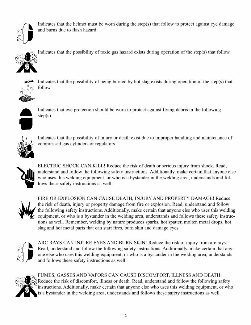
Indicates that the helmet must be worn during the step(s) that follow to protect against eye damage
and burns due to flash hazard.
Indicates that the possibility of toxic gas hazard exists during operation of the step(s) that follow.
Indicates that the possibility of being burned by hot slag exists during operation of the step(s) that
follow.
Indicates that eye protection should be worn to protect against flying debris in the following
step(s).
Indicates that the possibility of injury or death exist due to improper handling and maintenance of
compressed gas cylinders or regulators.
ELECTRIC SHOCK CAN KILL! Reduce the risk of death or serious injury from shock. Read,
understand and follow the following safety instructions. Additionally, make certain that anyone else
who uses this welding equipment, or who is a bystander in the welding area, understands and fol-
lows these safety instructions as well.
FIRE OR EXPLOSION CAN CAUSE DEATH, INJURY AND PROPERTY DAMAGE! Reduce
the risk of death, injury or property damage from fire or explosion. Read, understand and follow
the following safety instructions. Additionally, make certain that anyone else who uses this welding
equipment, or who is a bystander in the welding area, understands and follows these safety instruc-
tions as well. Remember, welding by nature produces sparks, hot spatter, molten metal drops, hot
slag and hot metal parts that can start fires, burn skin and damage eyes.
ARC RAYS CAN INJURE EYES AND BURN SKIN! Reduce the risk of injury from arc rays.
Read, understand and follow the following safety instructions. Additionally, make certain that any-
one else who uses this welding equipment, or who is a bystander in the welding area, understands
and follows these safety instructions as well.
FUMES, GASSES AND VAPORS CAN CAUSE DISCOMFORT, ILLNESS AND DEATH!
Reduce the risk of discomfort, illness or death. Read, understand and follow the following safety
instructions. Additionally, make certain that anyone else who uses this welding equipment, or who
is a bystander in the welding area, understands and follows these safety instructions as well.
2
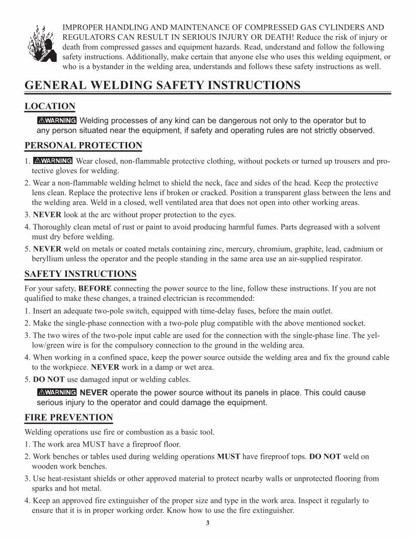
IMPROPER HANDLING AND MAINTENANCE OF COMPRESSED GAS CYLINDERS ANDREGULATORS CAN RESULT IN SERIOUS INJURY OR DEATH! Reduce the risk of injury ordeath from compressed gasses and equipment hazards. Read, understand and follow the followingsafety instructions. Additionally, make certain that anyone else who uses this welding equipment, orwho is a bystander in the welding area, understands and follows these safety instructions as well.
GENERAL WELDING SAFETY INSTRUCTIONSLOCATION
Welding processes of any kind can be dangerous not only to the operator but toany person situated near the equipment, if safety and operating rules are not strictly observed.
PERSONAL PROTECTION1. Wear closed, non-flammable protective clothing, without pockets or turned up trousers and pro-
tective gloves for welding.2. Wear a non-flammable welding helmet to shield the neck, face and sides of the head. Keep the protective
lens clean. Replace the protective lens if broken or cracked. Position a transparent glass between the lens andthe welding area. Weld in a closed, well ventilated area that does not open into other working areas.
3. NEVER look at the arc without proper protection to the eyes.4. Thoroughly clean metal of rust or paint to avoid producing harmful fumes. Parts degreased with a solvent
must dry before welding.5. NEVER weld on metals or coated metals containing zinc, mercury, chromium, graphite, lead, cadmium or
beryllium unless the operator and the people standing in the same area use an air-supplied respirator.
SAFETY INSTRUCTIONSFor your safety, BEFORE connecting the power source to the line, follow these instructions. If you are notqualified to make these changes, a trained electrician is recommended:1. Insert an adequate two-pole switch, equipped with time-delay fuses, before the main outlet.2. Make the single-phase connection with a two-pole plug compatible with the above mentioned socket.3. The two wires of the two-pole input cable are used for the connection with the single-phase line. The yel-
low/green wire is for the compulsory connection to the ground in the welding area.4. When working in a confined space, keep the power source outside the welding area and fix the ground cable
to the workpiece. NEVER work in a damp or wet area.5. DO NOT use damaged input or welding cables.
NEVER operate the power source without its panels in place. This could causeserious injury to the operator and could damage the equipment.
FIRE PREVENTIONWelding operations use fire or combustion as a basic tool.1. The work area MUST have a fireproof floor.2. Work benches or tables used during welding operations MUST have fireproof tops. DO NOT weld on
wooden work benches.3. Use heat-resistant shields or other approved material to protect nearby walls or unprotected flooring from
sparks and hot metal.4. Keep an approved fire extinguisher of the proper size and type in the work area. Inspect it regularly to
ensure that it is in proper working order. Know how to use the fire extinguisher.3
5. Remove all combustible materials from the work site. If you can not remove them, protect them with fire-proof covers.
NEVER perform welding operations on a container that has held toxic, com-bustible or flammable liquids or vapors. NEVER perform welding operations in an area con-taining combustible vapors, flammable liquids or explosive dust.
VENTILATIONVentilate welding work areas adequately. Maintain sufficient air flow to prevent
accumulation of explosive or toxic concentrations of gases. Welding operations using cer-tain combinations of metals, coatings and gases generate toxic fumes. Use respiratoryprotection equipment in these circumstances. BEFORE welding, read and understand theMaterial Safety Data Sheet for the welding alloy.
ELECTROMAGNETIC COMPATIBILITYBEFORE installing an Arc power source, inspect the surrounding area checking the following points:1. Make sure there are no other power supply cables, control lines, telephone cables or other devices close to
the power source.2. Make sure that telephones, televisions, computers or other control systems are not in the working area.3. People with pace-makers or hearing aides should keep far from the power source. In particular cases, special
protection measures may be required.
Reduce interference by following these suggestions:1. If there is interference in the power source line, mount an E.M.T. filter between the power supply and the
power source.2. Shorten the output cables of the power source, keep them together and connected to ground.3. Securely fasten the panels of the power source in place after performing maintenance.
HEALTH HAZARDSThe welding process can be hazardous to your health. Therefore, follow these precautions:1. ALWAYS wear protective clothing without pockets and cuffs. Wear a helmet, gloves and shoes with an
insulating sole.2. ALWAYS use a welding mask or helmet with the properly tinted protective glass in the shade adequate to
the welding operation being performed and to the current intensity.3. Make certain that bystanders in the welding area are also following these precautions.4. ALWAYS keep the welding mask glass clean. Replace it if it is cracked or chipped.5. NEVER weld in a damp area or come in contact with a moist or wet surface when welding.6. If the welding area lacks proper ventilation, use fume extractors. Avoid continuous inhalation of welding fumes.7. Clean the welding pieces from solvents or greases which develop toxic gases when exposed to heat.
ELECTRIC SHOCKELECTRIC SHOCK CAN KILL! Reduce the risk of death or serious injury from
shock. Read, understand and follow ALL safety instructions. Be sure that everyone who usesthis welding equipment or who is a bystander in the welding area understands and followsALL safety instructions as well.
4
ELECTRIC SHOCK CAN BE FATAL. A person qualified in First Aid tech-niques should ALWAYS be present in the working area. If a person is unconscious andelectric shock is suspected, DO NOT touch the person if he or she is in contact withcables. Disconnect power from the machine, then use First Aid. Use dry wood or otherinsulating materials to move cables, if necessary, away from the person.
1. Never touch or come in physical contact with any part of the input current circuit and welding current circuit.2. Frequently, check that the input cable and plug are in good condition.3. Make sure that the welder is disconnected from the main power supply BEFORE attempting any repairs,
opening the side panels of the machine or repairing the input cable.4. Fit the main line, BEFORE the distribution outlet, with a three-poles switch with adequate delayed fuses
(check the characteristics plate for fuse values).5. DO NOT weld with cables, torch or earth clamp in poor shape.6. DO NOT coil the torch or the earth cables around your body.7. Should you feel the slightest electrical shock, STOP welding IMMEDIATELY. DO NOT use the welder
until the fault is found and resolved.
WELDER SPECIFICATIONSYour new Forney ARC (SMAW) Welding System is designed for maintenance and sheet metal fabrication.The unit consists of a single-phase power transformer power source and arc stabilizer. This welding powersource is capable of welding with mild steel electrodes.
This unit is also capable of welding with high carbon steel, special alloy steel, cast iron, and nonferrous, suchas aluminum. The electrode material should correspond with the workpiece metal.
Flux coatings are made for use with either AC (Alternating Current), DC (direct current) reverse polarity, orDC straight polarity, although some function well on both AC and DC current.
Please refer to the instructions provided in this manual for proper machine setup.
WELDER OPERATING CHARACTERISTICSThe duty rating defines how long the welding system can be used before it must pause and cool down. DutyCycle ratings are expressed as a percentage of a ten-minute period. It represents the maximum welding timeallowed at the specified amperage setting. The remaining balance of a ten-minute period is required for coolingoff the unit.
Forney 120 volt and 230 volt Welding Systems have duty cycle ratings based on 20 amp and 50 amp inputcurrents. Please refer to the data plate located on the front of the unit for the specific rating that applies to yourunit.
All Forney 230 volt Welding Systems are rated at the required input amperage for proper operation. Pleaserefer to the data plate located on the front of the unit for the specific rating that applies to your unit.
5
6
Type . . . . . . . . . . . . . . . . . . . . . . . . . . . . . . . . . . . . . . . . . . . . . . . . . . . . . . . . .235 Amp ARC Welding SystemInput Voltage . . . . . . . . . . . . . . . . . . . . . . . . . . . . . . . . . . . . . . . . . . . . . . . . . . . . . . . . . . . . . . .230 Volt (60Hz)Rated Output . . . . . . . . . . . . . . . . . . . . . . . . . . . . . . . . . . . . . . . . . . . . . . . . . . . .235 Amps @ 20% Duty CycleAgency Listing . . . . . . . . . . . . . . . . . . . . . . . . . . . . . . . . . . . . . . . . .CSA Rated 200 Amps @ 20% Duty CycleMaximum Output . . . . . . . . . . . . . . . . . . . . . . . . . . . . . . . . . . . . . . . . . . . . . . . . . . . . . . . .235 Amps AC PeakOutput Power Settings . . . . . . . . . . . . . . . . . . . . . . . . . . . . . . . . . . . . . . . . . . . . . . . . . . .Shunt (45-235 Amps)Power Switch . . . . . . . . . . . . . . . . . . . . . . . . . . . . . . . . . . . . . . . . . . . . . . . . . . . . . .Illuminated On/Off SwitchPower Cord . . . . . . . . . . . . . . . . . . . . . . . . . . . . . . . . . . . . . . . . . . . . . . . . . . . . . . . .6 Ft Power Cord with PlugWelding Lead . . . . . . . . . . . . . . . . . . . . . . . . . . . . . . . . . .10 Ft Welding Cable and 300 Amp Electrode HolderGround Cable & Clamp . . . . . . . . . . . . . . . . . . . . . . . . . . . . . .10 Ft Ground Cable and 300 Amp Work ClampGround Cable Connection . . . . . . . . . . . . . . . . . . . . . . . . . . . . . . . . . . . . . . . . . . . . . . . . . . .Fixed ConnectionAccessories . . . . . . . . . . . . . . . . . . . . . . . . . . . . . . . . . . . . . . . . . . . . . . . . . . Wheel Kit and Handle (Optional)
Instruction Manual
Type . . . . . . . . . . . . . . . . . . . . . . . . . . . . . . . . . . . . . . . . . . . . . . . . . . .235 Amp AC/DC ARC Welding SystemInput Voltage . . . . . . . . . . . . . . . . . . . . . . . . . . . . . . . . . . . . . . . . . . . . . . . . . . . . . . . . . . . . . . .230 Volt (60Hz)Rated Output . . . . . . . . . . . . . . . . . . . . . . . . . . . . . . . . . . . . . . . . . . . . . . . . . . . .235 Amps @ 20% Duty CycleAgency Listing . . . . . . . . . . . . . . . . . . . . . . . . . . . . . . . . . . . . . .CSA Rated 200 Amps @ 20% Duty Cycle AC
CSA Rated 135 Amps @ 35% Duty Cycle DCMaximum Output . . . . . . . . . . . . . . . . . . . . . . . . . . . . . . . . . . . . . . . .230 Amps AC Peak / 185 Amps DC PeakOutput Power Settings . . . . . . . . . . . . . . . . . . . . . . . . . . . . . . . . . . . . . . . . . . . . . . . . . . .Shunt (45-235 Amps)Power Switch . . . . . . . . . . . . . . . . . . . . . . . . . . . . . . . . . . . . . . . . . . . . . . . . . . . . . .Illuminated On/Off SwitchPower Cord . . . . . . . . . . . . . . . . . . . . . . . . . . . . . . . . . . . . . . . . . . . . . . . . . . . . .6 Ft Power Cord without PlugWelding Lead . . . . . . . . . . . . . . . . . . . . . . . . . . . . . . . . . .10 Ft Welding Cable and 300 Amp Electrode HolderGround Cable & Clamp . . . . . . . . . . . . . . . . . . . . . . . . . . . . . .10 Ft Ground Cable and 300 Amp Work ClampGround Cable Connection . . . . . . . . . . . . . . . . . . . . . . . . . . . . . . . . . . . . . . . . . . . . . . . . . . .Dinse ConnectionAccessories . . . . . . . . . . . . . . . . . . . . . . . . . . . . . . . . . . . . . . . . . . . . . . . . . . Wheel Kit and Handle (Optional)
Instruction Manual
SPECIFICATIONS FOR 235FI AC ARC (SMAW) WELDING SYSTEM
SPECIFICATIONS FOR 235FI AC/DC ARC (SMAW) WELDING SYSTEM
WELDER INSTALLATION
POWER SOURCE CONNECTIONPower Requirements
Connection to Power SourceHigh voltage danger from power source! Consult a qualified electrician for
proper installation of receptacle at the power source.
This welder must be grounded while in use to protect the operator from electrical shock. If you are not sure if youroutlet is properly grounded, have it checked by a qualified electrician. DO NOT cut off the grounding prong or alterthe plug in any way. DO NOT use any adapters between the welder’s power cord and the power source receptacle.
WELDER ASSEMBLYThe following steps describe the assembly, installation, maintenance and operations of your new welder.
Be sure that the welder’s electrical power supply cord is not connectedwhile performing this procedure.
Avoid contacts with wires or parts. DO NOT work with the panels partially openedor removed completely from the power source.
1. Tools required: Hammer, Flat Head Screwdriver, Allen Wrench (metric)
7
235FI AC and 235FI AC/DC requires 230 Volt, 60 Hz, single phase AC with a 50 amp delayed fuse or circuit breaker. Please consult local codes for proper plug and receptacle applications. A qualified electrician should verify the ACTUAL VOLTAGE at the receptacle into which the welder will be plugged and confirm that the receptacle is properlygrounded. The use of the proper circuit size can eliminate the nuisance of circuit breaker tripping when welding.
DO NOT OPERATE THE 235FI AC OR 235FI AC/DC WELDER if the ACTUAL power source voltage is less than 220 Volts AC or greater than 240 Volts AC. Contact a qualified electrician if this problem exists. Improper performance and/or damage to the welder will result if operated on inadequate or excessive power.
Make sure the POWER switch is OFF. Connect the 235FI AC / 235FI AC/DC to a properly grounded 230 VAC, single-phase outlet. Contact a qualified electrician if a problem exists. Improper performance and/or damage to the welder results if operated on inadequate or excessive power.
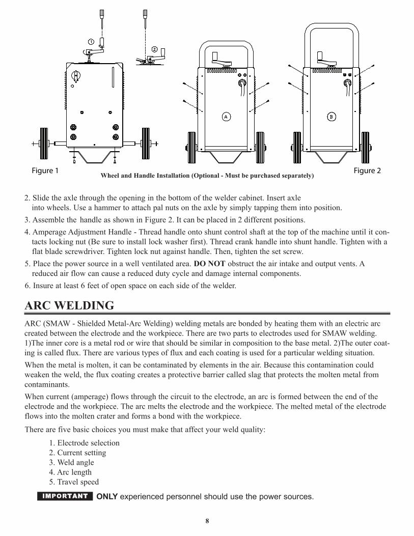
2. Slide the axle through the opening in the bottom of the welder cabinet. Insert axleinto wheels. Use a hammer to attach pal nuts on the axle by simply tapping them into position.
.snoitisop tnereffid 2 ni decalp eb nac tI .2 erugiF ni nwohs sa eldnah eht elbmessA .34. Amperage Adjustment Handle - Thread handle onto shunt control shaft at the top of the machine until it con-
tacts locking nut (Be sure to install lock washer first). Thread crank handle into shunt handle. Tighten with aflat blade screwdriver. Tighten lock nut against handle. Then, tighten the set screw.
5. Place the power source in a well ventilated area. DO NOT obstruct the air intake and output vents. Areduced air flow can cause a reduced duty cycle and damage internal components.
6. Insure at least 6 feet of open space on each side of the welder.
ARC WELDINGARC (SMAW - Shielded Metal-Arc Welding) welding metals are bonded by heating them with an electric arccreated between the electrode and the workpiece. There are two parts to electrodes used for SMAW welding.1)The inner core is a metal rod or wire that should be similar in composition to the base metal. 2)The outer coat-ing is called flux. There are various types of flux and each coating is used for a particular welding situation.When the metal is molten, it can be contaminated by elements in the air. Because this contamination couldweaken the weld, the flux coating creates a protective barrier called slag that protects the molten metal fromcontaminants. When current (amperage) flows through the circuit to the electrode, an arc is formed between the end of theelectrode and the workpiece. The arc melts the electrode and the workpiece. The melted metal of the electrodeflows into the molten crater and forms a bond with the workpiece.
There are five basic choices you must make that affect your weld quality:
1. Electrode selection2. Current setting3. Weld angle4. Arc length5. Travel speed
ONLY experienced personnel should use the power sources.IMPORTANT
Wheel and Handle Installation (Optional - Must be purchased separately)
8
Figure 1 Figure 2
MACHINE OPERATIONAC OUTPUT CONNECTIONS (235FI AC AND 235FI AC/DC) This welder has two AC outlet plugs that are clearly marked with the electrode and ground clamp symbols.
NEVER reverse cable connections as this could cause injury to the user as wellas the equipment!)
Connect the electrode output cable to the electrode connections and the ground cable to the ground connection.These connections are Dinse type connections and require that they be twisted into place in order to insure thebest connection. A slight twist is fine. You are now able to weld with 30 to 235 Amps of AC Power. Theopen circuit voltage of the AC connections is approximately 72 Volts.
ELECTRIC SHOCK CAN KILL! Reduce the risk of death or seriousinjury from shock. Read, understand and follow ALL safety instructions. Be sure thateveryone who uses this welding equipment or who is a bystander in the welding areaunderstands and follows ALL safety instructions as well.
ELECTRIC SHOCK CAN BE FATAL. A person qualified in First Aidtechniques should ALWAYS be present in the working area. If a person is uncon-scious and electric shock is suspected, DO NOT touch the person if he or she is incontact with commands. Disconnect power from the machine, then use First Aid.Use dry wood or other insulating materials to move cables, if necessary, away fromthe person.
DC OUTPUT CONNECTIONS (235FI AC/DC) If you have purchased the 235FI AC/DC Model, it has two DC outlet plugs marked DC+ and DC-. These plugs can be connected in either the DC direct current position or in the DC reverse polarity position. The DCconnectors are Dinse type connections and require a slight twist in order to insure the best possible connection.The open circuit voltage of the DC connectors is approximately 72 Volts.
ELECTRIC SHOCK CAN KILL! Reduce the risk of death or seriousinjury from shock. Read, understand and follow ALL safety instructions. Be sure thateveryone who uses this welding equipment or who is a bystander in the welding areaunderstands and follows ALL safety instructions as well.
ELECTRIC SHOCK CAN BE FATAL. A person qualified in First Aidtechniques should ALWAYS be present in the working area. If a person is uncon-scious and electric shock is suspected, DO NOT touch the person if he or she is incontact with commands. Disconnect power from the machine, then use First Aid.Use dry wood or other insulating materials to move cables, if necessary, away fromthe person.
SELECTING AC OR DC WELDING OUTPUTThe use of the proper type of welding current is determined by the type of repair that needs to be made.
AC CURRENT WELDINGAlternating current (AC) welding is performed when the welding cables are connected to the AC electrode andground jacks. This type of welding current is ideal for heavy plate steel in flat position welding.Most AC welding operations will be general purpose work on mild steel utilizing AWS rated 6011 and 7018type electrodes.
9
DIRECT CURRENT WELDINGDirect current DC welding is performed when the welding cables are connected to the DC+ (Positive) and DC-(Negative) output receptacles. The 235FI AC/DC offers you two DC welding options, straight or reverse polarity.
To weld with straight polarity place the electrode cable plugged into the receptacle market DC negative and theground cable or work cable plugged into the receptacle marked DC positive.
STRAIGHT POLARITY DC welding is ideal for:• Cutting steel;• Hardfacing work;• Build up work for heavy deposits.Reverse current DC welding is performed with the electrode cable plugged into the receptacle marked DC pos-itive and the ground cable or work cable plugged into the receptacle marked DC negative.
REVERSE POLARITY DC welding is ideal for:• Overhead welding;• Vertical welding;• Cast Iron welding;• Heavy Aluminum welding;• Rivet welding;• Sheet Metal welding;• Low Hydrogen Electrode welding;• Arc Bronze Electrode welding.Most DC welding processes are performed in the reverse polarity position.
ADJUSTING AMPERAGE/INCREASING AMPERAGESimply crank the amperage adjustment handle on top of welder clockwise. As you crank the handle you willsee the amperage indicator located in the sight glass on the amperage setting scale move upward increasing theamperage. Stop cranking when you have reached the desired amperage range.
LOWERING THE AMPERAGESimply crank the amperage adjustment handle on top of welder counter clockwise. As you crank the handleyou will see the amperage indicator located in the sight glass on the amperage setting scale move downward.Stop cranking when you have reached the desired amperage range.
Be sure that the amperage adjustment handle is secured properly and that thescrew and nut are tight. Failure to do so will result in the inability to adjust amperage. Also becareful not to over tighten the connections which could result in damage to the unit.
PREPARATIONS FOR WELDINGYour work should be performed in a safe, comfortable and organized area. The work area should be free of allflammables with both a fire extinguisher and bucket of sand available for emergencies. To properly preparefor welding follow these simple instructions:1. Prepare an organized well lighted work area.2. Follow the instructions for personal protection (page 3) for yourself as well as those around you.3. Make sure you've studied all safety instructions found at the front of this manual.4. Set up the workpiece and make the ground clamp connection.
10
5. Select the appropriate electrode.6. Turn on the power switch of your welder.
Arc rays can injure eyes and burn skin! Prolonged exposure to arc rayscan cause blindness and burns. NEVER strike an arc or begin welding without ade-quate eye and skin protection. Follow our Health Hazard safety instructions onpage 4 before welding.
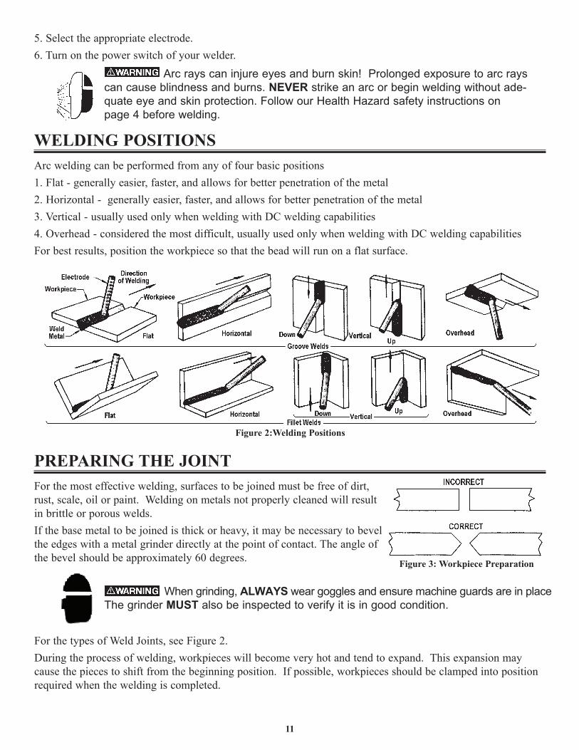
WELDING POSITIONSArc welding can be performed from any of four basic positions1. Flat - generally easier, faster, and allows for better penetration of the metal2. Horizontal - generally easier, faster, and allows for better penetration of the metal3. Vertical - usually used only when welding with DC welding capabilities4. Overhead - considered the most difficult, usually used only when welding with DC welding capabilitiesFor best results, position the workpiece so that the bead will run on a flat surface.
PREPARING THE JOINTFor the most effective welding, surfaces to be joined must be free of dirt,rust, scale, oil or paint. Welding on metals not properly cleaned will resultin brittle or porous welds.If the base metal to be joined is thick or heavy, it may be necessary to bevelthe edges with a metal grinder directly at the point of contact. The angle ofthe bevel should be approximately 60 degrees.
When grinding, ALWAYS wear goggles and ensure machine guards are in placeThe grinder MUST also be inspected to verify it is in good condition.
For the types of Weld Joints, see Figure 2. During the process of welding, workpieces will become very hot and tend to expand. This expansion maycause the pieces to shift from the beginning position. If possible, workpieces should be clamped into positionrequired when the welding is completed.
11
Figure 3: Workpiece Preparation
Figure 2:Welding Positions
GROUND CLAMP CONNECTIONBe certain you have a solid ground connection. The ground clamp connection is part of the current circuit. Apoor connection at the ground clamp will result in wasted power and heat. Scrape away any dirt, rust, scale, oilor paint you may find on the workpiece. Make sure the ground clamp directly touches the metal surface.
SELECTING THE ELECTRODE
HIGH VS. LOW VOLTAGE ELECTRODESBe sure you have the best electrode for the welding job you are doing. Electrode manufacturers make moststandard welding electrodes in two basic types:1. Designed to run on welders with High Open Circuit Voltage.2. Designed to run on welders with Low Open Circuit Voltage.Most welding is done with Low Open Circuit Voltage AC rods such as E-6013 or E07014 general purposerods. See Rod Table. Use rods of 1/16", 5/64" or 3/32" diameter. High Open Circuit Voltage rods such as 6010, 6011, 7018, etc. will not work with most low power welders of100 Amps or smaller. Electrode manufacturers have adopted a uniform marking code for rods. Each electrode is marked with a pre-fix letter and four numbers. Each of the numbers has particular significance. For example, a commonly usedgeneral purpose electrode is marked E-6013. The E signifies the electrode is for electric arc applications.The first two digits in the number indicate the minimum tensile strength of the deposited metal, in thousands ofpounds per square inch. In this instance, 60 indicates the melting rod will have a minimum tensile strength of60,000 p.s.i. The third number indicates the welding position for which the rod is intended. A number 1 indi-cates it is for use in any position.Number 2 represents an electrode restricted to welding in horizontal and flat positions. Number 3 represents anelectrode intended for use in a flat position only. The fourth digit shows some specific characteristics of theelectrode such as weld quality, type of current or amount of penetration. For all practical purposes, the fourthposition marking will not affect the rod you would normally purchase.
12
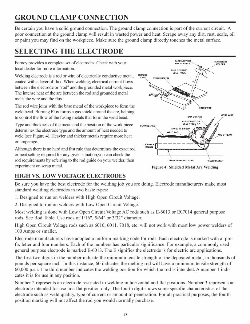
Figure 4: Shielded Metal Arc Welding
Forney provides a complete set of electrodes. Check with your local dealer for more information.Welding electrode is a rod or wire of electrically conductive metal, coated with a layer of flux. When welding, electrical current flows between the electrode or "rod" and the grounded metal workpiece. The intense heat of the arc between the rod and grounded metal melts the wire and the flux. The rod wire joins with the base metal of the workpiece to form the weld bead. Burning Flux forms a gas shield around the arc, helping to control the flow of the fusing metals that form the weld bead.Type and thickness of the metal and the position of the work piece determines the electrode type and the amount of heat needed to weld (see Figure 4). Heavier and thicker metals require more heat or amperage.Although there is no hard and fast rule that determines the exact rod or heat setting required for any given situation,you can check the rod requirements by referring to the rod guide on your welder, then experiment on scrap metal.
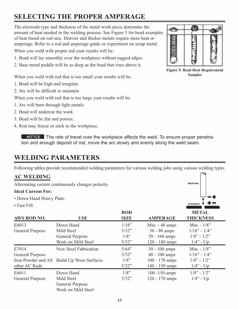
SELECTING THE PROPER AMPERAGEThe electrode type and thickness of the metal work-piece determine theamount of heat needed in the welding process. See Figure 5 for bead examplesof heat based on rod size. Heavier and thicker metals require more heat oramperage. Refer to a rod and amperage guide or experiment on scrap metal.When you weld with proper rod your results will be:1. Bead will lay smoothly over the workpiece without ragged edges.2. Base metal puddle will be as deep as the bead that rises above it.
When you weld with rod that is too small your results will be:1. Bead will be high and irregular.2. Arc will be difficult to maintainWhen you weld with rod that is too large your results will be:1. Arc will burn through light metals.2. Bead will undercut the work.3. Bead will be flat and porous.4. Rod may freeze or stick to the workpiece.
The rate of travel over the workpiece affects the weld. To ensure proper penetra-tion and enough deposit of rod, move the arc slowly and evenly along the weld seam.
WELDING PARAMETERSFollowing tables provide recommended welding parameters for various welding jobs using various welding types.
AC WELDINGAlternating current continuously changes polarity.Ideal Current For:• Down Hand Heavy Plate.• Fast Fill.
LATEMDORAWS ROD NO. USE SIZE AMPERAGE THICKNESSE6013 Down Hand 1/16” Min. - 40 amps Min. - 1/8”General Purpose Mild Steel 3/32” 30 - 80 amps 1/16” - 1/4”
General Purpose 1/8” 70 - 160 amps 1/8” - 1/2”Work on Mild Steel 5/32” 120 - 180 amps 1/4” - Up
E7014 New Steel Fabrication 5/64” 30 - 100 amps Min. - 1/8”General Purpose 3/32” 40 - 100 amps 1/16” - 1/4”Iron Powder and All Build Up Worn Surfaces 1/8” 100 - 170 amps 1/8” - 1/2”other AC Rods 5/32” 140 - 150 amps 1/4” - UpE6011 Down Hand 1/8” 100 -150 amps 1/8” - 1/2”General Purpose Mild Steel 5/32” 120 - 170 amps 1/4” - Up
General PurposeWork on Mild Steel
13
Figure 5: Bead Heat RequirementSamples
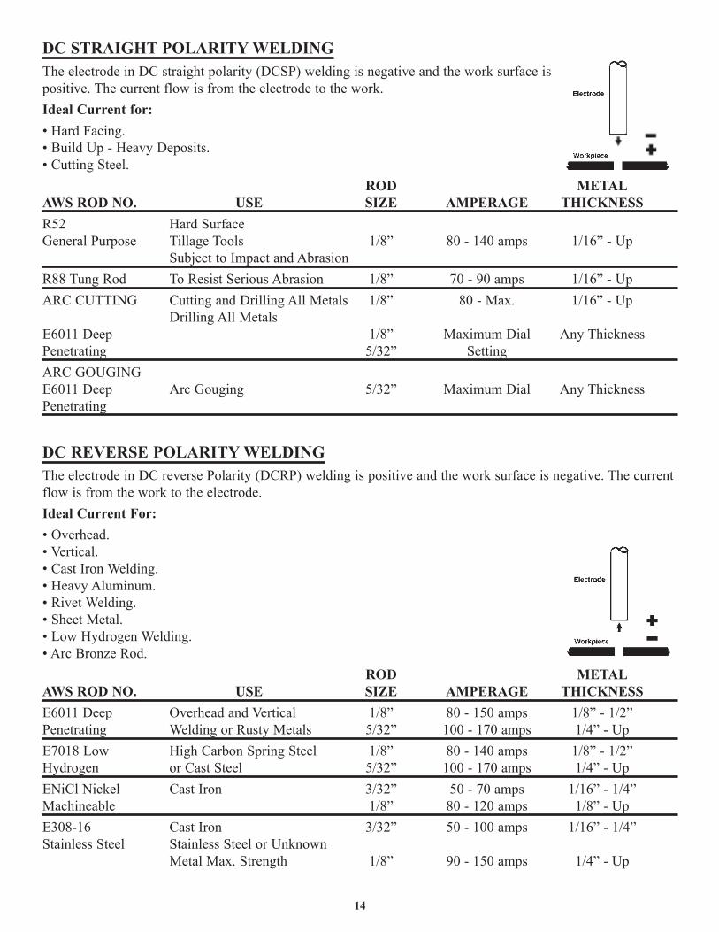
DC STRAIGHT POLARITY WELDINGThe electrode in DC straight polarity (DCSP) welding is negative and the work surface ispositive. The current flow is from the electrode to the work.Ideal Current for:• Hard Facing.• Build Up - Heavy Deposits.• Cutting Steel.
LATEMDORAWS ROD NO. USE SIZE AMPERAGE THICKNESSR52 Hard SurfaceGeneral Purpose Tillage Tools 1/8” 80 - 140 amps 1/16” - Up
Subject to Impact and AbrasionR88 Tung Rod To Resist Serious Abrasion 1/8” 70 - 90 amps 1/16” - UpARC CUTTING Cutting and Drilling All Metals 1/8” 80 - Max. 1/16” - Up
Drilling All MetalsssenkcihT ynAlaiD mumixaM”8/1peeD 1106E
Penetrating 5/32” SettingARC GOUGINGE6011 Deep Arc Gouging 5/32” Maximum Dial Any ThicknessPenetrating
DC REVERSE POLARITY WELDINGThe electrode in DC reverse Polarity (DCRP) welding is positive and the work surface is negative. The currentflow is from the work to the electrode.Ideal Current For:• Overhead.• Vertical.• Cast Iron Welding.• Heavy Aluminum.• Rivet Welding.• Sheet Metal.• Low Hydrogen Welding.• Arc Bronze Rod.
LATEMDORAWS ROD NO. USE SIZE AMPERAGE THICKNESSE6011 Deep Overhead and Vertical 1/8” 80 - 150 amps 1/8” - 1/2”Penetrating Welding or Rusty Metals 5/32” 100 - 170 amps 1/4” - UpE7018 Low High Carbon Spring Steel 1/8” 80 - 140 amps 1/8” - 1/2”Hydrogen or Cast Steel 5/32” 100 - 170 amps 1/4” - UpENiCl Nickel Cast Iron 3/32” 50 - 70 amps 1/16” - 1/4”Machineable 1/8” 80 - 120 amps 1/8” - Up
”4/1 - ”61/1spma 001 - 05”23/3norI tsaC61-803EStainless Steel Stainless Steel or Unknown
Metal Max. Strength 1/8” 90 - 150 amps 1/4” - Up
14
15
E6013 Sheet Metal 1/16” Min. - 60 amps Min. - 1/16”General Purpose 3/32” 30 - 80 amps 1/16” - 1/8”E7014General Purpose Sheet Metal 5/64” Min. - 100 amps Min. - 1/4”Iron Powder
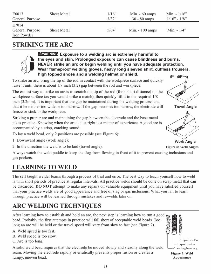
STRIKING THE ARCExposure to a welding arc is extremely harmful to
the eyes and skin. Prolonged exposure can cause blindness and burns.NEVER strike an arc or begin welding until you have adequate protection.Wear flameproof welding gloves, heavy long sleeved shirt, cuffless trousers,high topped shoes and a welding helmet or shield.
To strike an arc, bring the tip of the rod in contact with the workpiece surface and quicklyraise it until there is about 1/8 inch (3.2) gap between the rod and workpiece. The easiest way to strike an arc is to scratch the tip of the rod (for a short distance) on theworkpiece surface (as you would strike a match), then quickly lift it to the required 1/8inch (3.2mm). It is important that the gap be maintained during the welding process andthat it be neither too wide or too narrow. If the gap becomes too narrow, the electrode willfreeze or stick to the workpiece. Striking a proper arc and maintaining the gap between the electrode and the base metaltakes practice. Knowing when the arc is just right is a matter of experience. A good arc isaccompanied by a crisp, cracking sound. To lay a weld bead, only 2 positions are possible (see Figure 6): 1. Downward angle (work angle);2. In the direction the weld is to be laid (travel angle).Always watch the weld puddle to keep the slag from flowing in front of it to prevent causing inclusions andgas pockets.
LEARNING TO WELDThe self taught welder learns through a process of trial and error. The best way to teach yourself how to weldis with short periods of practice at regular intervals. All practice welds should be done on scrap metal that canbe discarded. DO NOT attempt to make any repairs on valuable equipment until you have satisfied yourselfthat your practice welds are of good appearance and free of slag or gas inclusions. What you fail to learnthrough practice will be learned through mistakes and re-welds later on.
ARC WELDING TECHNIQUESAfter learning how to establish and hold an arc, the next step is learning how to run a goodbead. Probably the first attempts in practice will fall short of acceptable weld beads. Toolong an arc will be held or the travel speed will vary from slow to fast (see Figure 7).A. Weld speed is too fast.B. Weld speed is too slow.C. Arc is too long.A solid weld bead requires that the electrode be moved slowly and steadily along the weldseam. Moving the electrode rapidly or erratically prevents proper fusion or creates alumpy, uneven bead.
Figure 6: Weld Angles
Figure 7: WeldAppearance
Exposure to a Welding arc is extremely harmful to the eyes and skin.Prolonged exposure can cause blindness and burns. NEVER strike an arc or beginwelding until you are adequately protected. Wear flameproof welding gloves, a heavylong-sleeved shirt, cuffless trousers, high-topped shoes and a welding helmet.
To prevent ELECTRIC SHOCK, DO NOT perform any welding whilestanding, kneeling or lying directly on the grounded work.
TYPES OF COMMONLY USED WELD BEADSThe following paragraphs discuss the most commonly used arc welding beads.
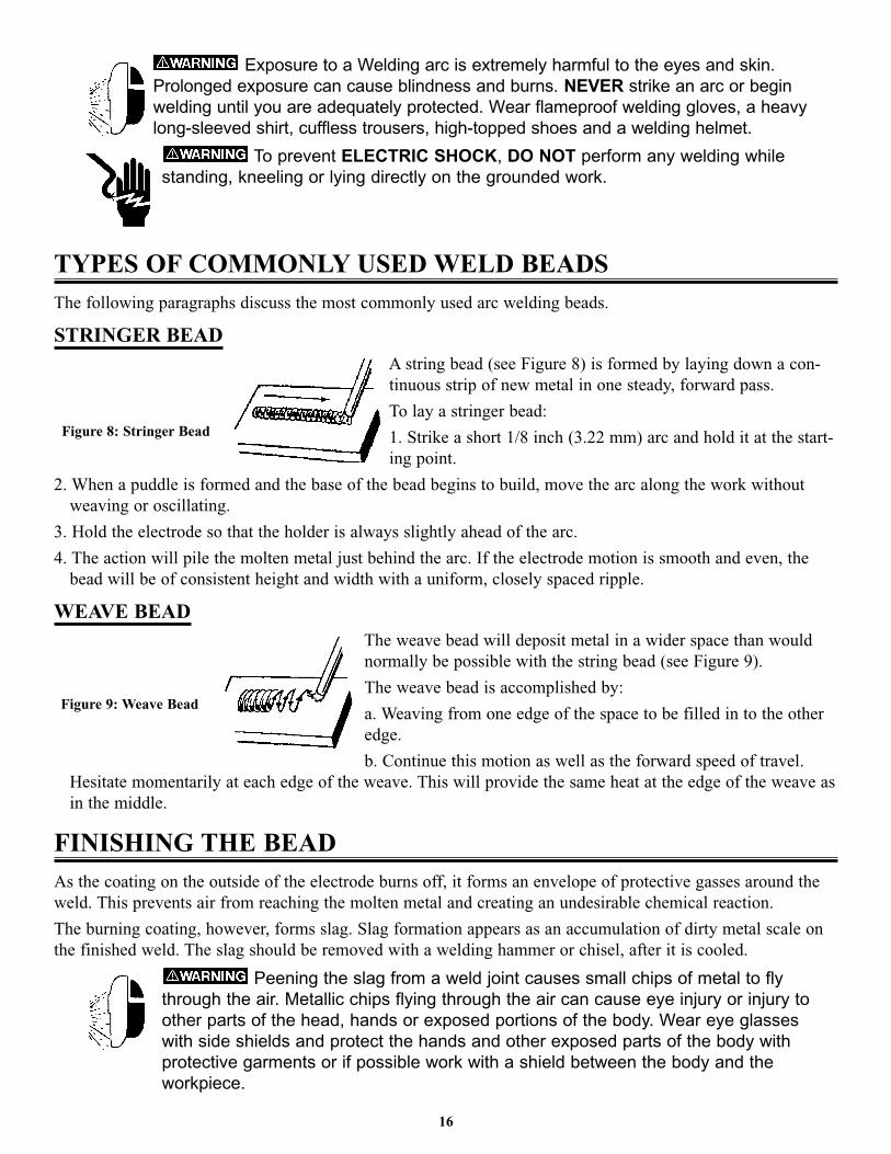
STRINGER BEADA string bead (see Figure 8) is formed by laying down a con-
tinuous strip of new metal in one steady, forward pass.
To lay a stringer bead:
1. Strike a short 1/8 inch (3.22 mm) arc and hold it at the start-
ing point.
2. When a puddle is formed and the base of the bead begins to build, move the arc along the work without
weaving or oscillating.
3. Hold the electrode so that the holder is always slightly ahead of the arc.
4. The action will pile the molten metal just behind the arc. If the electrode motion is smooth and even, the
bead will be of consistent height and width with a uniform, closely spaced ripple.
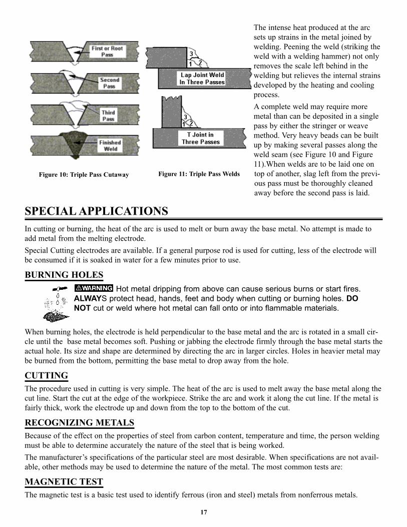
WEAVE BEADThe weave bead will deposit metal in a wider space than would
normally be possible with the string bead (see Figure 9).
The weave bead is accomplished by:
a. Weaving from one edge of the space to be filled in to the other
edge.
b. Continue this motion as well as the forward speed of travel.
Hesitate momentarily at each edge of the weave. This will provide the same heat at the edge of the weave as
in the middle.
FINISHING THE BEADAs the coating on the outside of the electrode burns off, it forms an envelope of protective gasses around the
weld. This prevents air from reaching the molten metal and creating an undesirable chemical reaction.
The burning coating, however, forms slag. Slag formation appears as an accumulation of dirty metal scale on
the finished weld. The slag should be removed with a welding hammer or chisel, after it is cooled.
Peening the slag from a weld joint causes small chips of metal to flythrough the air. Metallic chips flying through the air can cause eye injury or injury toother parts of the head, hands or exposed portions of the body. Wear eye glasseswith side shields and protect the hands and other exposed parts of the body withprotective garments or if possible work with a shield between the body and theworkpiece.
16
Figure 9: Weave Bead
Figure 8: Stringer Bead
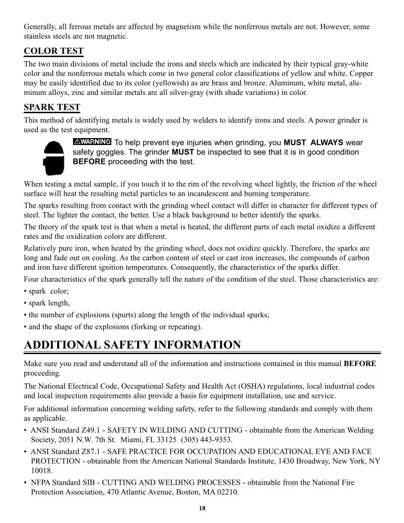
The intense heat produced at the arc
sets up strains in the metal joined by
welding. Peening the weld (striking the
weld with a welding hammer) not only
removes the scale left behind in the
welding but relieves the internal strains
developed by the heating and cooling
process.
A complete weld may require more
metal than can be deposited in a single
pass by either the stringer or weave
method. Very heavy beads can be built
up by making several passes along the
weld seam (see Figure 10 and Figure
11).When welds are to be laid one on
top of another, slag left from the previ-
ous pass must be thoroughly cleaned
away before the second pass is laid.
SPECIAL APPLICATIONSIn cutting or burning, the heat of the arc is used to melt or burn away the base metal. No attempt is made to
add metal from the melting electrode.
Special Cutting electrodes are available. If a general purpose rod is used for cutting, less of the electrode will
be consumed if it is soaked in water for a few minutes prior to use.
BURNING HOLES
Hot metal dripping from above can cause serious burns or start fires.ALWAYS protect head, hands, feet and body when cutting or burning holes. DONOT cut or weld where hot metal can fall onto or into flammable materials.
When burning holes, the electrode is held perpendicular to the base metal and the arc is rotated in a small cir-
cle until the base metal becomes soft. Pushing or jabbing the electrode firmly through the base metal starts the
actual hole. Its size and shape are determined by directing the arc in larger circles. Holes in heavier metal may
be burned from the bottom, permitting the base metal to drop away from the hole.
CUTTINGThe procedure used in cutting is very simple. The heat of the arc is used to melt away the base metal along the
cut line. Start the cut at the edge of the workpiece. Strike the arc and work it along the cut line. If the metal is
fairly thick, work the electrode up and down from the top to the bottom of the cut.
RECOGNIZING METALSBecause of the effect on the properties of steel from carbon content, temperature and time, the person welding
must be able to determine accurately the nature of the steel that is being worked.
The manufacturer’s specifications of the particular steel are most desirable. When specifications are not avail-
able, other methods may be used to determine the nature of the metal. The most common tests are:
MAGNETIC TESTThe magnetic test is a basic test used to identify ferrous (iron and steel) metals from nonferrous metals.
17
Figure 10: Triple Pass Cutaway Figure 11: Triple Pass Welds
Generally, all ferrous metals are affected by magnetism while the nonferrous metals are not. However, some
stainless steels are not magnetic.
COLOR TESTThe two main divisions of metal include the irons and steels which are indicated by their typical gray-white
color and the nonferrous metals which come in two general color classifications of yellow and white. Copper
may be easily identified due to its color (yellowish) as are brass and bronze. Aluminum, white metal, alu-
minum alloys, zinc and similar metals are all silver-gray (with shade variations) in color.
SPARK TESTThis method of identifying metals is widely used by welders to identify irons and steels. A power grinder is
used as the test equipment.
To help prevent eye injuries when grinding, you MUST ALWAYS wearsafety goggles. The grinder MUST be inspected to see that it is in good conditionBEFORE proceeding with the test.
When testing a metal sample, if you touch it to the rim of the revolving wheel lightly, the friction of the wheel
surface will heat the resulting metal particles to an incandescent and burning temperature.
The sparks resulting from contact with the grinding wheel contact will differ in character for different types of
steel. The lighter the contact, the better. Use a black background to better identify the sparks.
The theory of the spark test is that when a metal is heated, the different parts of each metal oxidize a different
rates and the oxidization colors are different.
Relatively pure iron, when heated by the grinding wheel, does not oxidize quickly. Therefore, the sparks are
long and fade out on cooling. As the carbon content of steel or cast iron increases, the compounds of carbon
and iron have different ignition temperatures. Consequently, the characteristics of the sparks differ.
Four characteristics of the spark generally tell the nature of the condition of the steel. Those characteristics are:
• spark color;
• spark length,
• the number of explosions (spurts) along the length of the individual sparks;
• and the shape of the explosions (forking or repeating).
ADDITIONAL SAFETY INFORMATION
Make sure you read and understand all of the information and instructions contained in this manual BEFOREproceeding.
The National Electrical Code, Occupational Safety and Health Act (OSHA) regulations, local industrial codes
and local inspection requirements also provide a basis for equipment installation, use and service.
For additional information concerning welding safety, refer to the following standards and comply with them
as applicable.
• ANSI Standard Z49.1 - SAFETY IN WELDING AND CUTTING - obtainable from the American Welding
Society, 2051 N.W. 7th St. Miami, FL 33125 (305) 443-9353.
• ANSI Standard Z87.1 - SAFE PRACTICE FOR OCCUPATION AND EDUCATIONAL EYE AND FACE
PROTECTION - obtainable from the American National Standards Institute, 1430 Broadway, New York, NY
10018.
• NFPA Standard SIB - CUTTING AND WELDING PROCESSES - obtainable from the National Fire
Protection Association, 470 Atlantic Avenue, Boston, MA 02210.
18

• CGA Pamphlet P-I - SAFE HANDLING OF COMPRESSED GASSES IN CYLINDERS - obtainable fromthe Compressed Gas Association, 5005th Avenue, New York, NY 10038.
• OSHA Standard 29 CFR, Part 1910, Subpart 0. - WELDING, CUTTING AND BRAZING - obtainable fromyour state OSHA office.
• CSA Standard W117.2 - CODE FOR SAFETY IN WELDING AND CUTTING - obtainable from CanadianStandards Association, 178 Rexdale Blvd., Rexdale, Ontario Canada M9W 1R3.
• American Welding Society Standard A6.0 - WELDING AND CUTTING CONTAINERS WHICH HAVEHELD COMBUSTIBLES - obtainable from the American Welding Society, 2051 N.W. 7th St., Miami, FL33125 (305) 443-9353.
WARNING: This product contains chemicals, including lead, or otherwise produces chemicals known to the State of California to cause cancer, birth defects and other reproductive harm. Wash hands after handling. (California Health & Safety Code § 25249.5 et seq.)
19
20
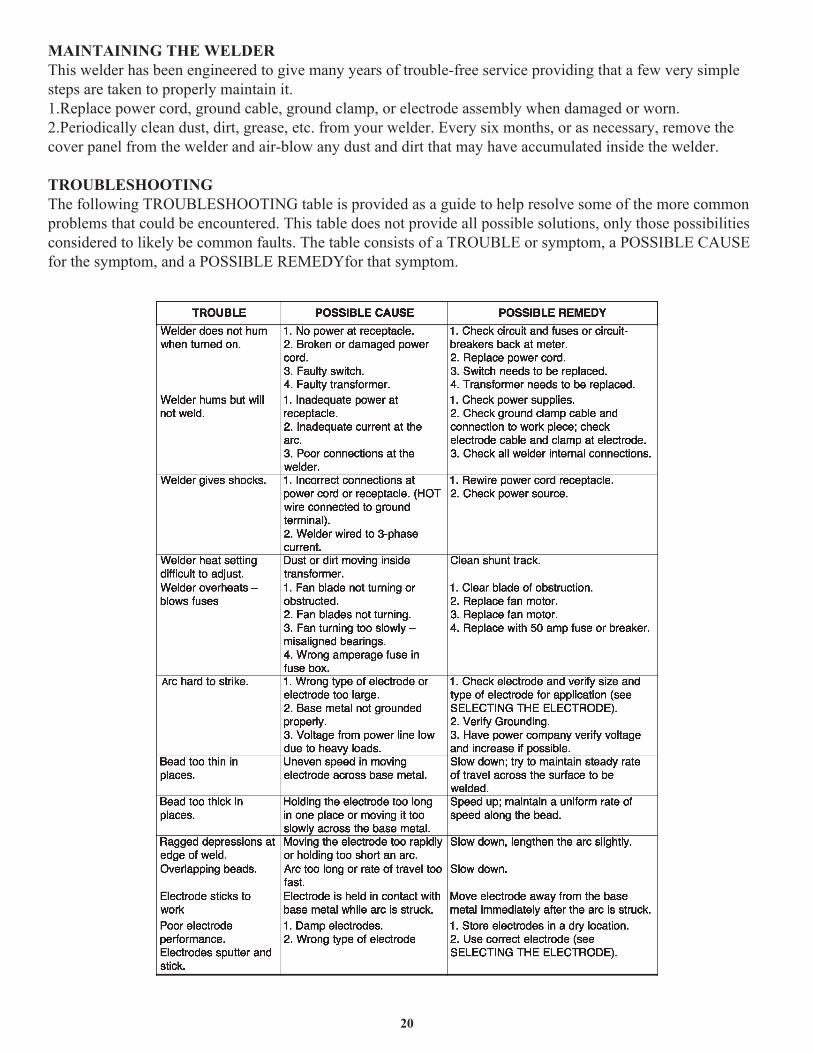
MAINTAINING THE WELDERThis welder has been engineered to give many years of trouble-free service providing that a few very simple steps are taken to properly maintain it.1.Replace power cord, ground cable, ground clamp, or electrode assembly when damaged or worn.2.Periodically clean dust, dirt, grease, etc. from your welder. Every six months, or as necessary, remove the cover panel from the welder and air-blow any dust and dirt that may have accumulated inside the welder.
TROUBLESHOOTINGThe following TROUBLESHOOTING table is provided as a guide to help resolve some of the more common problems that could be encountered. This table does not provide all possible solutions, only those possibilities considered to likely be common faults. The table consists of a TROUBLE or symptom, a POSSIBLE CAUSE for the symptom, and a POSSIBLE REMEDYfor that symptom.
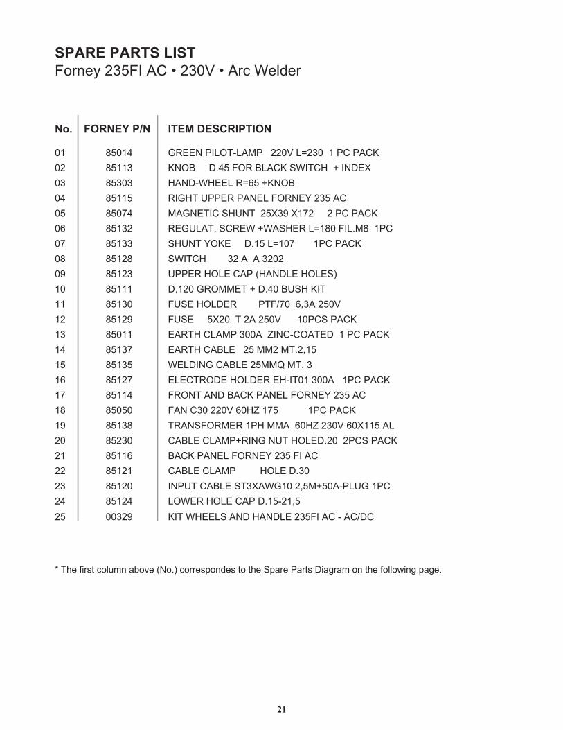
SPARE PARTS LISTForney 235FI AC • 230V • Arc Welder
* The first column above (No.) correspondes to the Spare Parts Diagram on the following page.
No. FORNEY P/N
01 8501485113
85115
85132851338512885123851118513085129
85137851358512785114
85138
8511685121851208512400329
0203 853030405 850740607080910111213 850111415161718 850501920 852302122232425
ITEM DESCRIPTION
GREEN PILOT-LAMP 220V L=230 1 PC PACKKNOB D.45 FOR BLACK SWITCH + INDEXHAND-WHEEL R=65 +KNOBRIGHT UPPER PANEL FORNEY 235 ACMAGNETIC SHUNT 25X39 X172 2 PC PACKREGULAT. SCREW +WASHER L=180 FIL.M8 1PCSHUNT YOKE D.15 L=107 1PC PACKSWITCH 32 A A 3202UPPER HOLE CAP (HANDLE HOLES) D.120 GROMMET + D.40 BUSH KITFUSE HOLDER PTF/70 6,3A 250VFUSE 5X20 T 2A 250V 10PCS PACKEARTH CLAMP 300A ZINC-COATED 1 PC PACKEARTH CABLE 25 MM2 MT.2,15WELDING CABLE 25MMQ MT. 3ELECTRODE HOLDER EH-IT01 300A 1PC PACKFRONT AND BACK PANEL FORNEY 235 ACFAN C30 220V 60HZ 175 1PC PACKTRANSFORMER 1PH MMA 60HZ 230V 60X115 ALCABLE CLAMP+RING NUT HOLED.20 2PCS PACKBACK PANEL FORNEY 235 FI ACCABLE CLAMP HOLE D.30
KIT WHEELS AND HANDLE 235FI AC - AC/DC
INPUT CABLE ST3XAWG10 2,5M+50A-PLUG 1PCLOWER HOLE CAP D.15-21,5
21
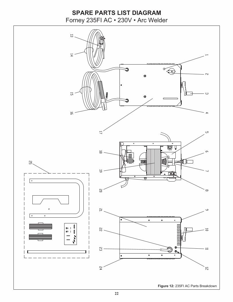
SPARE PARTS LIST DIAGRAMForney 235FI AC • 230V • Arc Welder
Figure 12: 235FI AC Parts Breakdown
22
25
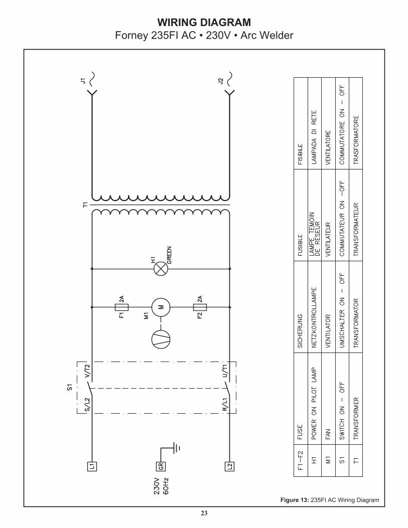
WIRING DIAGRAMForney 235FI AC • 230V • Arc Welder
23
Figure 13: 235FI AC Wiring Diagram
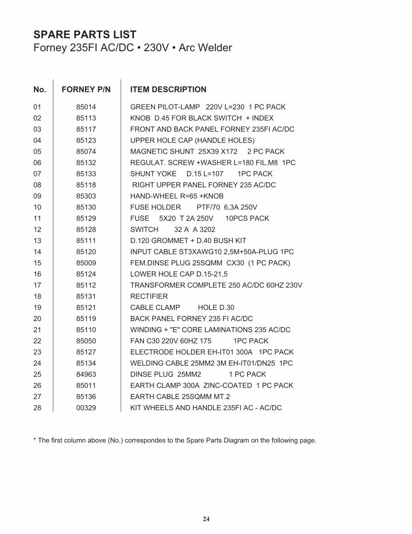
SPARE PARTS LISTForney 235FI AC/DC • 230V • Arc Welder
* The first column above (No.) correspondes to the Spare Parts Diagram on the following page.
24
FORNEY P/NNo.
4105810203040
4705850607080
30358900111213141
9005851617181910212
05058223242
36948521105862
72
KCAP CP 1 032=L V022 PMAL-TOLIP NEERGXEDNI + HCTIWS KCALB ROF 54.D BONK
CD/CA IF532 YENROF LENAP KCAB DNA TNORF)SELOH ELDNAH( PAC ELOH REPPU
KCAP CP 2 271X 93X52 TNUHS CITENGAMCP1 8M.LIF 081=L REHSAW+ WERCS .TALUGER
KCAP CP1 701=L 51.D EKOY TNUHSCD/CA 532 YENROF LENAP REPPU THGIR
BONK+ 56=R LEEHW-DNAHV052 A3,6 07/FTP REDLOH ESUF
KCAP SCP01 V052 A2 T 02X5 ESUF2023 A A 23 HCTIWS
TIK HSUB 04.D + TEMMORG 021.DCP1 GULP-A05+M5,2 01GWAX3TS ELBAC TUPNI)KCAP CP 1( 03XC MMQS52 GULP ESNID.MEF
5,12-51.D PAC ELOH REWOLV032 ZH06 CD/CA 052 ETELPMOC REMROFSNART
REIFITCER03.D ELOH PMALC ELBAC
CD/CA IF 532 YENROF LENAP KCABCD/CA 532 SNOITANIMAL EROC "E" + GNIDNIW
KCAP CP1 571 ZH06 V022 03C NAFKCAP CP1 A003 10TI-HE REDLOH EDORTCELECP1 52ND/10TI-HE M3 2MM52 ELBAC GNIDLEW
KCAP CP 1 2MM52 GULP ESNIDKCAP CP 1 DETAOC-CNIZ A003 PMALC HTRAE
2.TM MMQS52 ELBAC HTRAECD/CA - CA IF532 ELDNAH DNA SLEEHW TIK28
ITEM DESCRIPTION
851138511785123
851328513385118
8513085129851288511185120
851248511285131851218511985110
8512785134
8513600329
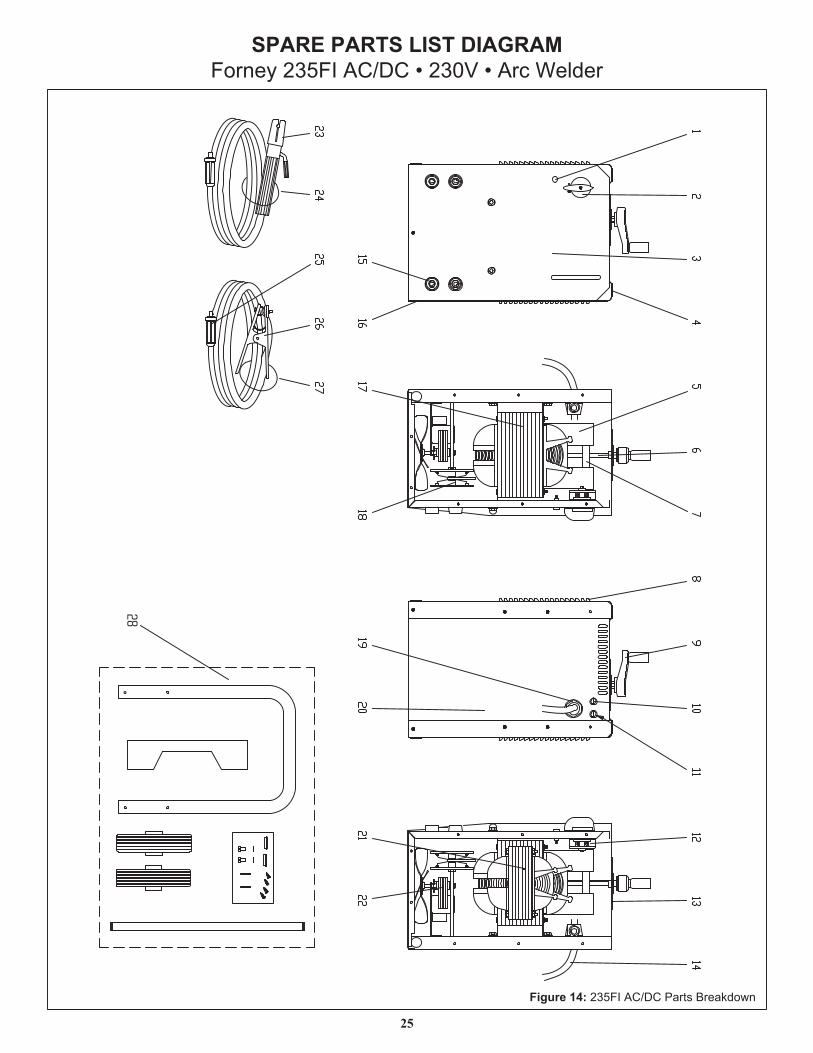
SPARE PARTS LIST DIAGRAMForney 235FI AC/DC • 230V • Arc Welder
25
28
Figure 14: 235FI AC/DC Parts Breakdown
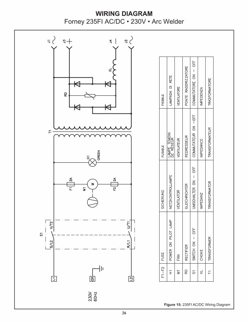
WIRING DIAGRAMForney 235FI AC/DC • 230V • Arc Welder
26
Figure 15: 235FI AC/DC Wiring Diagram
27
Forney 5/3/1 Limited WarrantyEffective August 1st, 2009
1. Limited Warranty: Subject to the terms and conditions below, Forney Industries, Inc., Fort Collins, Colorado, warrants to its original retail purchaser that the new Forney equipment sold after the effective date of this limited warranty is free of defects in material and workmanship at the time it is shipped by Forney. This is in lieu of all other warranties, express or implied.
2. Notification: Please call 1-800-521-6038 with your warranty questions. You can also visit www.forneywelding.forneyind.com for additional information about your new welder.
3. Length of Warranty: Within the warranty periods listed below, Forney will repair or replace any warranted parts or components that fail due to defects in material or workmanship. Warranty is effective from the date of original retail purchase. Warranty duration is as follows: a) 5 years: Original main power rectifiers transformers, stabilizers and reactors.b) 3 years: Switches and Controls.c) 1 year: Lead assembly and accessories.
4. Non-Applicable Parts: Forney's limited warranty shall not apply to consumables such as contact tips, cutting nozzles, felt wire cleaner, drive rollers, gas diffusers, plasma torch tips and electrodes, weld cables, tips and parts that fail due to normal wear. In addition, this warranty does not extend to any damage caused by the untimely replacement or maintenance of any of the previously listed consumable parts.
5. Warrantor: Forney Industries 1830 LaPorte Avenue Fort Collins, CO 80521 1-800-521-6038 www.forneywelding.forneyind.com
6. Purchaser / Warranty: The original purchaser of the Forney Industries product. The warranty is not transferable. Forney Industries products are intended for purchase and use by persons trained and experienced in the use and maintenance of welding equipment.
7. What is not covered under the warranty: a) Implied warranties, including those of merchantability and fitness for a particular purpose are limited in duration to this
express warranty. After this period, all risks of loss, from whatever reason, shall be on the purchaser. b) Any incidental, indirect, or consequential loss, damage, or expense that may result from any defect, failure or malfunction
of the Fomey product. c) Any failure that results from accident, purchaser's abuse, neglect or failure to operate products in accordance with
instructions provided in the owner's manual(s) supplied with the product. d) Pre-delivery service, i.e. assembly and adjustment.
8. Claim: In the event of a warranty claim under this warranty, the exclusive remedies shall be, at Forney Industries sole option: a) Repair; or b) Replacement; or c) Where authorized in writing by Forney Industries, the cost of repair or replacement at an authorized Forney Industries
Service Center; or d) Payment of or credit for the purchase price less reasonable depreciation based on actual use upon the return of the goods at
the customer's risk and expense.
8. Purchaser will:a) Contact Forney's Customer Service at 1-800-521-6038 within 30 days of the defect or failure. b) Provide dated proof of purchase (typically a purchase receipt). c) Provide the serial number. Registering your welder at www.forneywelding.forneyind.com will speed up this process. d) Deliver or ship welder to a Forney authorized Service Center. Freight &/or packaging costs, if any, must be borne by the purchaser.

FORNEY ACCESSORIES
11-1/2" X 27-1/2"3-Level Portable
Welder CartCat. No. 00332
Electrodes (Sticks)
Chipping HammerCat. No. 70601
Magswitch® Ground ClampCat. No. 58559
GlovesCat. No. 55203
Auto Darkening HelmetsCat. Nos. 55698 & 55699
Wire BrushesCat. No. 70520
Electrode HolderCat. No. 56205
Magswitch® 90° Angle SquareCat. No. 58565
Forney Industries1830 LaPorte Ave.
Fort Collins, CO 80521
1-800-521-6038www.forneyind.com
Grinding WheelCat. No. 71876
Flame Retardant CoverallsCat. No. 57182
Leather Welding SleevesCat. No. 57200
Leather Waist Welding ApronCat. No. 57202