23. hydraulic analysis - general principles
TRANSCRIPT

101
PART II
23. HYDRAULIC ANALYSIS - GENERAL PRINCIPLES
Hydraulic analysis simply consists of applying basic hydraulic laws to the flow of sewage effluent through
soil. However, there are certain differences between the way that leaching systems are assumed to function
by hydraulic analysis and the way that they actually do function. For instance, hydraulic analysis assumes a
constant and continuous flow of sewage effluent through saturated soil. It is known that, under normal
conditions, sewage effluent is dispersed into the soil surrounding leaching systems in an unsaturated and
discontinuous flow. Depending on seasonal conditions, effluent may be dispersed by atmospheric
evaporation or may accumulate within the leaching system or surrounding soil. However, the continuous,
saturated flow conditions assumed for hydraulic analysis probably will occur before a leaching system fails.
A mound of saturated soil will form under the leaching system where the hydraulic capacity of the
surrounding soil is limited. This will rise to surround the leaching system as failure approaches. In this
situation, the leaching system itself will be continuously filled with sewage effluent causing fluctuating
sewage discharges from the building served to be equalized into a steady flow into the soil. Where the soil
surrounding a leaching system is poor or where there is high ground water, flat slopes or underlying ledge
or hardpan, hydraulic analysis is a useful tool for estimating the maximum capacity of the leaching system
to disperse effluent into the surrounding soil without breakout.
Using Hydraulic Analysis For Small Leaching Systems - In general, hydraulic analysis should not be used
for the design or regulation of household or other small sewage disposal systems with a capacity of 1,000
gallons or less where the site is generally favorable for leaching purposes. Conformance to the
requirements of the Public Health Code and the general design principles outlined in Part I of this manual
should assure a satisfactory system. Hydraulic analysis becomes important where the capacity of the
surrounding soil is limited. Reference should be made to the section on “Hydraulic Analysis - Examples”
before requiring any hydraulic analysis beyond what is called for under Minimum Leaching System Spread
(MLSS) criteria.
Hydraulic analysis may be required for either of two separate purposes. The most common purpose is to
indicate the nature and probable magnitude of the hydraulic limitations on a particular site so that the
leaching system can be designed to overcome those limitations. When hydraulic analysis is used for design
purposes, the accepted practice is to make an analysis based on existing site conditions, maximum ground
water levels and conservative sewage flow estimates. This results in a conservative leaching system design,
which is what is desired.
Hydraulic analysis also may be used as a regulatory basis for rejection of proposed subsurface sewage
disposal systems in extremely limited or unfavorable locations. Hydraulic analysis may depend heavily on
certain specific assumptions or approximations which must be made for each particular site. Therefore, the
reliability of the analysis depends on the validity and accuracy of the assumptions and, ultimately, on the
experience and judgment of the investigator. As might be expected, disagreements are common when
hydraulic analysis is used for regulatory purposes. For this reason, a formal hydraulic analysis, other than
the MLSS calculation, should rarely be necessary if all other requirements of the Public Health Code are
met.
102
In general, no leaching system should be approved on the basis of favorable hydraulic analysis unless it also
meets Code requirements.
When hydraulic analysis is used for regulatory purposes, certain adjustments normally are made to allow
for site improvements such as ground water intercepting drains, filling and grading to promote rainfall
runoff. The beneficial effects these improvements have on the hydraulic conditions in the area of the
proposed leaching system may be applied to the analysis and approval process.
Darcy's Law - The flow of sewage effluent and ground water through soils may be analyzed by using a basic
hydraulic formula referred to as "Darcy's Law". This formula assumes a constant and continuous gravity
flow through unconfined "channels" or areas of saturated soil. In its simplest form, Darcy's Law states that
the velocity of a liquid moving through an unconfined channel under gravity conditions is proportional to
the loss of hydraulic head per unit length of flow path, or:
V = K X (H1 - H2 / L)
Where:
V = Velocity of flow
K = Coefficient of permeability
H1-H2= Loss of hydraulic head
L = Length of flow channel
Darcy's Law generally is used in a modified form for hydraulic analysis of sewage and shallow ground
water flow. In this analysis, the main concern is the volume of water which will flow through an area of
saturated soil in a given period of time. This sometimes is called the hydraulic conductivity of the soil. The
equation is usually written:
Q = K i A
Where:
Q = The hydraulic conductivity or saturated flow rate, usually expressed
in cubic feet per day.
K = The coefficient of permeability of the soil through which the saturated
flow takes place. This is usually expressed in feet per day.
i = The slope of the hydraulic grade. When used in hydraulic analysis of
sewage or shallow ground water flow, only the horizontal length of the
flow channel normally is considered since the flow channel usually
follows the ground surface and is relatively flat. Therefore, i normally
is expressed as a dimensionless fraction or decimal representing a vertical
drop divided by a horizontal distance.
A = The cross sectional area of saturated flow, usually expressed in square feet.

103
It is evident from the form of this equation that if either the permeability, the slope of the hydraulic grade or
the cross sectional area of saturated flow is limited, the hydraulic conductivity of the soil is likewise
limited.
Determining Soil Permeability - The coefficient of permeability, or simply the permeability of the soil, is a
measure of how easily liquid passes through a particular soil. This depends on such things as the
distribution of the particle sizes in the soil and their shape and geometrical arrangement. The permeability
of naturally occurring soils can be quite variable due to stratification of different particle sizes, varying
degrees of compaction and the existence of naturally occurring drainage channels formed by percolating
ground water. It is not unusual for the permeability to vary by a factor of 1,000 in small samples taken from
various soil layers at different locations or depths on the same site. There also may be considerable
difference between the horizontal and vertical permeability in the same soil at the same location and depth.
Horizontal permeabilities usually are much greater than vertical permeabilities due to the effect of layering,
particle orientation and natural drainage channels. Because of this variability, considerable judgment must
be used in determining the permeability of naturally occurring soils.
While the permeability is a definite physical property of a soil, it should be understood that the overall
permeability of any site or any portion of the naturally occurring soil on the site can only be estimated. It
cannot be measured directly. Estimates of site permeability can be based on four general types of
measurements or observations.
1. Estimates based on ground water observations made on the site.
2. Estimates based on in-place testing on the site.
3. Estimates based on testing of soil samples.
4. Estimates based on soil identification and reference to available data.
The most appropriate method for estimating the permeability depends mainly on the soil and site conditions.
The season or time of year also is an important consideration since most field tests or observations depend
on ground water being present. In many cases, the most reliable method of estimating the overall site
permeability for sewage disposal purposes is by observations of ground water levels on the site. This is
particularly true where shallow or stratified soil layers are involved. In-place pit bailing tests are quite
reliable and may be used for estimating the permeability of deep soil layers. Estimating overall site
permeability on the basis of sample testing or soil identification requires considerable experience and
judgment on the part of the investigator. However, this may be done in the absence of seasonal ground
water and the field procedures are quite simple.
Wherever possible, the permeability should be estimated by more than one method. If the estimates are
fairly close, it can be assumed that no errors of judgment have been made in selecting or performing the test
and that the estimated permeability is valid for hydraulic analysis. Refer to the Section 25 titled “Methods
of Estimating Soil Permeability” for a detailed discussion of the various procedures for estimating soil
permeability. Only those procedures which are recommended for the particular conditions existing on the
site should be used. Particular attention should be given to the special precautions which should be taken
when using each method.
Determining The Hydraulic Grade - The slope of the hydraulic grade depends on the direction and slope of
the flow channel. Where layers of compact hardpan or ledge underlie a leaching system, sewage effluent
flows in a generally horizontal direction following the ground surface. In this case, the slope of the
hydraulic grade is equal to the difference in elevation of the underlying impervious layer at two observation
pits, divided by the distance between the pits. If only horizontal distances are considered and minor

104
variations in depth of underlying impervious layer are disregarded, the slope of the hydraulic grade may be
taken to be equal to the slope of the ground surface (refer to Figure 23-1).
Figure 23-1
Horizontal flow also may be assumed to exist in slowly permeable soils even though underlying impervious
boundary layers are not apparent. In this case, the slope of the hydraulic grade may be taken to be equal to
the difference in the ground water elevation at two observation pits divided by the distance between the pits
(refer to Figure 23-2). If variations in depth to the ground water table are minor, the slope of the hydraulic
grade also may be taken to be equal to the slope of the ground's surface.
UNDERLYING HARDPAN
Flow
Flow
Perched Ground Water
Ground Surface
150 ft.
Test Pit No. 1, Elev. = 108
Hardpan at 3.5 ft.
Perched Ground Water at 3 ft.
Test Pit No. 2, Elev. = 105
Hardpan at 4.0 ft.
Perched Ground Water at 3 ft.
i = Slope of Ground Surface
= 108 - 105 = 0.02
150

105
Figure 23-2
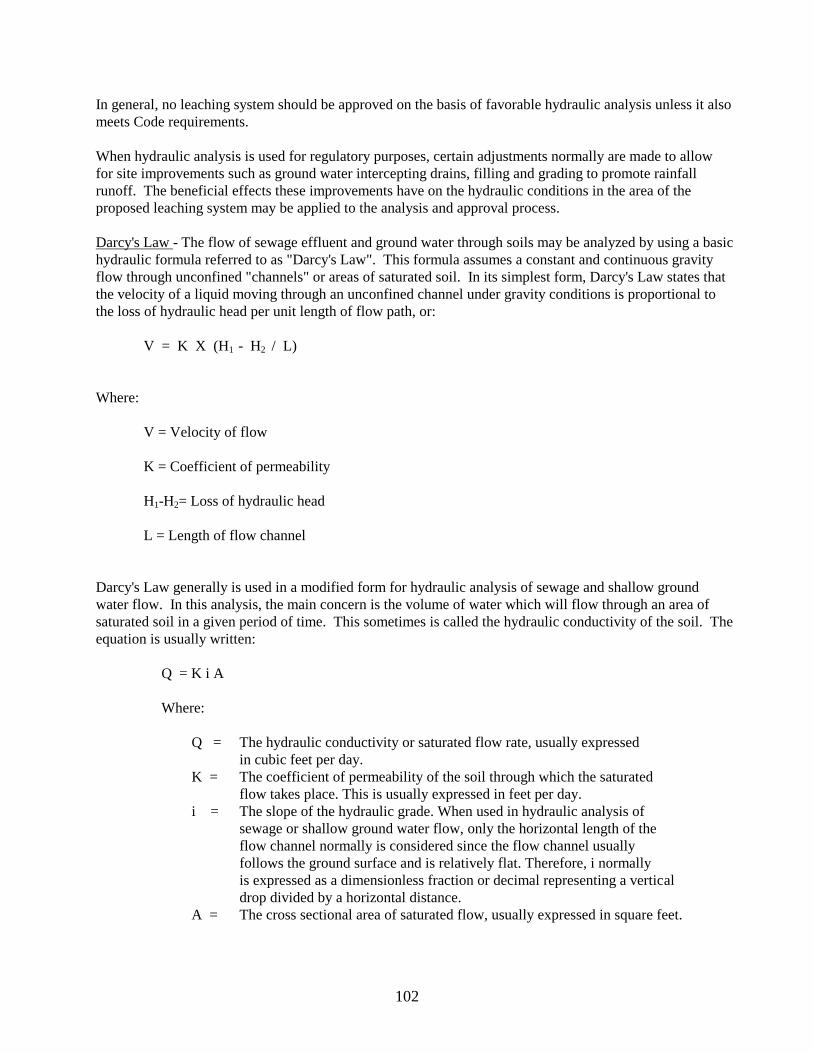
A mound of saturated soil will form under the leaching system where there are hydraulic constraints in the
surrounding soil. This mound of saturated soil constitutes part of the effluent flow channel and its formation
increases the slope of the hydraulic grade of the flow channel. Therefore, it is evident that constructing a
leaching system in fill above the surrounding ground surface will increase the slope of the hydraulic grade
and enhance the ability of the system to disperse effluent into the surrounding soil. Increasing the slope of
the hydraulic grade in this manner normally is not considered when using hydraulic analysis to design a
leaching system because such systems should be designed on conservative assumptions. However, when
hydraulic analysis is used for regulatory purposes, it is reasonable to allow certain minor adjustments to be
made in the hydraulic grade of the leaching system by elevating it in fill. Where leaching systems are
located over underlying impervious layers, it may be assumed that the upper end of the hydraulic grade is at
the bottom of the proposed leaching system but not higher than the original grade. The lower end can be
assumed to be the elevation of the impervious layer at a distance 50 feet downslope. The 50 foot distance
represents the normal maximum horizontal extent of the saturation mound, as indicated by field experience
(refer to Figure 23-3)*. Similarly, where there is no underlying boundary layer, the lower end of the
hydraulic grade may be assumed to be at the elevation of the ground water table 50 feet downslope from the
leaching system.
200 ft.
Test Pit No. 2, Elev. = 87
Firm Silty Loam
Ground Water at 4.0 ft.
Test Pit No. 1, Elev. = 95
Firm Silty Loam
Ground Water at 6.0 Ft.
Ground Surface
Ground Water Table
Slowly Permeable Soil
i = (95-6) - (87-4) = 0.03
200
106
Figure 23-3
*The exact horizontal extent of the saturation mound depends on the rate at which potential energy (system
elevation) is converted into kinetic energy (flow velocity). This in turn depends on the soil permeability,
with the more permeable soils having less extensive mounding.
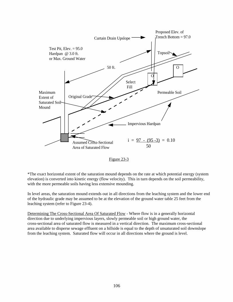
In level areas, the saturation mound extends out in all directions from the leaching system and the lower end
of the hydraulic grade may be assumed to be at the elevation of the ground water table 25 feet from the
leaching system (refer to Figure 23-4).
Determining The Cross-Sectional Area Of Saturated Flow - Where flow is in a generally horizontal
direction due to underlying impervious layers, slowly permeable soil or high ground water, the
cross-sectional area of saturated flow is measured in a vertical direction. The maximum cross-sectional
area available to disperse sewage effluent on a hillside is equal to the depth of unsaturated soil downslope
from the leaching system. Saturated flow will occur in all directions where the ground is level.
O
O 50 ft.
Impervious Hardpan
Permeable Soil
Topsoil
Select
Fill
Original GradeMaximum
Extent of
Saturated Soil
Mound
Test Pit, Elev. = 95.0
Hardpan @ 3.0 ft.
or Max. Ground Water
Curtain Drain Upslope
Proposed Elev. of
Trench Bottom = 97.0
i = 97 - (95 -3) = 0.10
50Assumed Cross-Sectional
Area of Saturated Flow
107
Figure 23-4
The cross-sectional area of unsaturated soil downslope from a leaching system can be increased by
spreading the system perpendicular to the direction of the slope. Assuming that the volume of effluent to be
dispersed remains constant, the depth of the area of saturated flow is reduced. (Refer back to Figure 11-2)
It is evident that where horizontal flow occurs, the depth of unsaturated soil available for effluent dispersal
may be increased by spreading fill over the naturally occurring soil surrounding the leaching system. This
would enhance effluent dispersal and prevent breakout within the filled area. This concept is routinely
employed in the repair of sewage disposal systems which failed due to hydraulic overloading. However,
breakout still may occur from the naturally occurring soil at the toe of the fill, particularly when located on
a slope For this reason, leaching systems normally should not be designed in this manner. Even though it is
possible to calculate the combined permeability of both original soils and fill placed on the lot, it is
extremely important to realize that wherever the fill material ends, the underlying original soil has to have
sufficient capacity to absorb and disperse projected flows. Bleed out of partially treated effluent is
unacceptable. Sewage disposal systems which depend upon filtration and detention in fill material prior to
discharging at the surface of the ground, water course or subsurface drain cannot be approved by local
health departments (refer to Figure 23-5).
10 ft.
25 ft.
2 ft.
O O
Test Pit Elev. = 90.0
Ground Water @ 2.0 ft.
Select Fill
Elevation of
Trench Bottom = 91.0
Original Grade
Original Grade
Elevation 90.0
Slowly Permeable Soil
Ground Water Table
Assumed Cross-Sectional
Area of Saturated Flow
Assumed Max.
Extent of Saturated
Soil Mound
i = 90.0 - (90.0-2.0) = 0.08
25

108
Figure 23-5
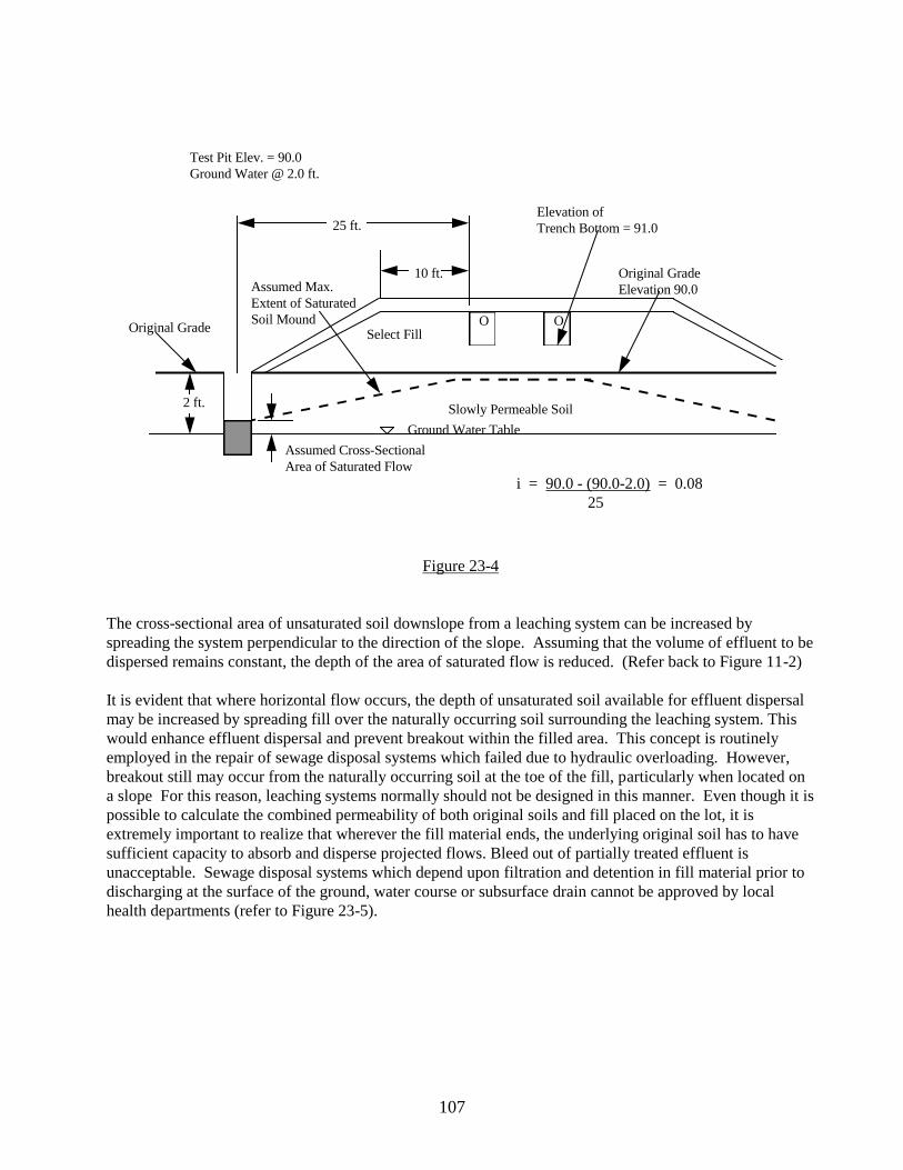
Where there is a deep layer of permeable soil underlying a leaching system, sewage effluent will flow
downward. Such downward flow is impeded where the underlying permeable soil is saturated and
horizontal flow may be assumed where the saturated underlying soil is only moderately permeable.
However, where the underlying soil is quite permeable (percolation rate of 5 minutes per inch or faster),
downward flow still will occur. This is particularly true for small sewage disposal systems where the
effluent flow volume is small relative to the storage volume of the permeable soil underlying the system.
Such soils may be considered to be unconfined aquifers and downward flow into the aquifer may be
assumed. It would be a mistake to assume that no flow occurs simply because the ground water table is
level. Hydraulic limitations are slight where these soil conditions exist and hydraulic analysis normally is
not necessary (refer to Figure 23-6).
Determining The Required Hydraulic Conductivity - The naturally occurring soil surrounding leaching
systems should be capable of hydraulically dispersing the entire volume of sewage effluent discharged into
it on a continuous basis. Ideally, it also should be capable of dispersing any ground water flowing into the
area of the leaching system from higher elevation, as well as any rain falling in the immediate area of the
system. In theory, any hydraulic analysis of the surrounding soil should take into count all of these sources
of flow. However, for small leaching systems, it has been found to be much more realistic to design the
systems with such site improvements as ground water intercepting drains or fill which will eliminate or
mitigate the effects of seasonal ground water or rainfall accumulations. The justification for this is more
fully explained in Section 25.
O 50 ft.
15 ft.
Select Fill
Extended Select
Fill
Original Ground Surface
Plowed or Scarified
Impervious Hardpan
Cross-Sectional Area
of Saturated Flow
109
Figure 23-6
In practice, hydraulic analyses made for the design of small leaching systems consider only the hydraulic
conductivity in the surrounding soil necessary to disperse the expected daily volume of sewage effluent
discharged to the system. For single family dwellings, a figure of 150 gallons per bedroom per day should
be used. Other daily usages from non-residential type buildings should be based on figures contained in
Table No. 4 in the Technical Standards Section of the Public Health Code or on more detailed flow
estimates provided by the design engineer.
Designing For Seasonal Rainfall Accumulation And Ground Water Movement - In Connecticut, rainfall
accumulates at an average rate of about 0.01 cubic feet per day for each square foot of ground surface
during the months of November through April. This is primarily because atmospheric evaporation is very
low during this period. The primary goal is designing the system so that it will not be adversely affected by
temporary or seasonal rainfall accumulation. This can be assured for small leaching systems by following
the design recommendations in Part I of this manual. The bottom of the leaching system should be kept at
least 18 inches above the maximum ground water level and at least 18 inches above any impervious soil
layer. This assures a depth of at least 30 inches of unsaturated soil surrounding the leaching system (not
counting the topsoil layer). Typically, a substantial portion of this soil consists of fill. Assuming a
drainable porosity of 0.2, this surrounding soil would contain about 0.5 cubic feet of available storage per
square foot of ground surface. This would be sufficient to store all rainfall received for a period of about 50
days during the wet season, even if all of it infiltrates into the soil. Actually, the percentage of rainfall
runoff during this season can be quite substantial, particularly during the winter months when the ground is
frozen. Runoff can be further enhanced by proper leaching system design. Normally, the finished ground
surface over the system is sloped 5 to 10% and is loamed, grassed and kept mowed to promote runoff. The
width of small leaching systems usually does not exceed 25 feet, allowing surface runoff to be effectively
diverted from the area of the system. Because of these considerations, seasonal accumulation of rainfall
o o o
200 ft.
Leaching System Installed
in Select FillElev. 100.0
Original
Ground
Level Ground Water Table 95.0Saturated Soil Mound
Effluent Flow Channels
Pond or
Stream
Permeable Soils - Perc. Rate 5 min./inch or Faster
Maximum i = 100.0 - 95.0 = 0.025
200

110
may be disregarded in hydraulic analysis of a small leaching systems on sloped lots where curtain drains
can be installed up gradient from the system.
Ground water movement from higher elevation into the area of the leaching system can hydraulically
overload the surrounding soil causing the system to fail. However, experience has shown that this is
unlikely to be a significant problem for a small leaching system except where there is a shallow underlying
layer of impervious soil or ledge. In this situation, most of the seasonal rainfall accumulation moves from
higher elevation on top of the impervious layer. Such perched ground water can be effectively intercepted
by a properly designed and constructed curtain drain and diverted from the area of the leaching system.
Ground water movement through the underlying impervious layer is minimal. In most such cases, the
intercepting drain can be assumed to be 100% effective and perched ground water moving into the area
from higher elevation can be disregarded in the hydraulic analysis.
Where there is no underlying impervious layer or where the slope of the ground surface is relatively flat,
curtain drains may be ineffective. Leaching systems usually are constructed in fill in such situations and
curtain drains may not be used or may be used only as an extra safeguard. In these situations, the maximum
ground water in the area of the leaching system must be carefully determined by field observation during
the wet season. Once the maximum ground water level has been determined, an analysis may be made to
determine the hydraulic conductivity of the unsaturated soil layers above this maximum level since only this
soil would be available for dispersal of sewage effluent. If such design procedures are followed, it should
not be necessary to provide for dispersal of seasonal ground water in most hydraulic analyses made for
small leaching systems.

111
24. METHODS OF ESTIMATING SOIL PERMEABILITY
The following methods of estimating soil permeability are recommended for use in connection with
hydraulic analysis of small subsurface sewage disposal systems receiving less than 2,000 gallons of sewage
per day. Other methods are not recommended for this particular use, for various reasons. For instance,
disturbed, recompacted tube samples are widely used for permeability tests in connection with construction
of dams, etc. However, they could produce questionable results for naturally occurring soil other than clean
sand or gravel because the permeability in naturally occurring soils depends to a large extent on particle
orientation and arrangement and on naturally formed drainage channels which are disturbed by
recompaction. Block samples are of little value since normally they can only be collected from layers of
compact soil which should be avoided for sewage disposal purposes Observations of falling ground water
levels following rainfall can be used to estimate the permeability of saturated soil layers. However, this is
practical only where the soil is quite permeable. Hydraulic analysis should not be necessary for the design
of small sewage disposal systems in such soils. Wherever possible, soil permeability should be estimated
by two or more methods for confirmation purposes. Site conditions should be considered when selecting
the methods to be used.
NOTE: In all of the following methods of determining the soil permeability (K), it is assumed that we are
evaluating a one foot slice of soil to determine the area of saturated flow (A), therefore, A = 1 ft. x d
Method A - Observation of Perched Ground Water During The Spring
Site Conditions - This method is most reliable for estimating the permeability of a sloping layer of relatively
loose, well draining soil (minimum percolation rate of 10 minutes per inch or better) underlain by compact
hardpan or ledge. In this situation there is a relatively large seasonal flow of ground water through a
relatively small flow channel formed by the looser upper soil layer. The cross-sectional area of the flow
channel is proportional to the depth of the perched watertable above the underlying impervious boundary
layer and the slope of the hydraulic grade is approximately the same as the ground slope. Therefore, if the
volume of ground water flowing through the upper soil layer can be estimated, the permeability of the layer
can be calculated using Darcy's Law.
Procedure - Field procedures are extremely quick and simple, but judgment must be used in deciding when
and where to make ground water observations. Observations should only be made during the early spring
after all frost is out of the ground. April probably is the most favorable month since, at this time of the year,
the upper soil layers are damp, atmospheric evaporation is at a minimum and rainfall runoff is usually low.
The observation pits should be dug in an area where the slope is smoothly contoured. Swales, gullies or
depressions should be avoided since these will cause a concentration of ground water flow which will result
in inaccurate permeability calculations.
Several observation pits should be dug in the area and, at each location, the depth of the perched water on
top of the underlying impervious layer should be carefully measured. The average slope of the ground
surface in the area also should be measured using a tripod or hand-held level. The drainage area must be
determined either by measurements in the field or from a USGS topographic map. If the observation pits
have been properly located on a smoothly contoured slope, the drainage area may be measured in profile
from the pits upslope to the high point of land perpendicular to the ground contours.

112
Permeability Calculation - During this time of year in Connecticut, the amount of perched ground water
flowing through the looser upper soil layers is roughly equal to the average rate at which rainfall is
collected on the upslope drainage area minus a factor of 50% to account for surface runoff. Therefore, a
rate of 0.005 cubic feet per day for each square foot of upslope drainage area will be utilized.
K = Q = 0.005 X w
iA S X d
Where:
K = Soil permeability, in feet per day.
w = Upslope drainage area, in square feet. (Length x 1 foot wide slice)
S = Average ground slope (drop, in feet/horizontal distance, in feet)
d = Depth of perched water table, in feet.
Example: (refer to Figure 24-1) - It is found that during April, a perched water table averaging about 2 feet
in depth exists in the loose soil on top of an underlying layer of impervious hardpan (percolation rate poorer
than 60 minutes per inch). The ground in this area slopes about 5 feet in 100 feet, and the drainage area
extends about 500 feet upslope from the location of the observation pits. Therefore:
K = 0.005 X 500 = 25 ft./day
0.05 X 2
Figure 24-1
500 ft.
2 ft.
Perched Ground
Water 2 ft. Above
Hardpan Layer
Test Pit Dug During
Maximum Ground
Water Conditions
Ground Surface -
Avg. Slope = 0.05
Permeable Soil
(Min. Perc. < 10 Min./In.)
Hardpan Layer
(Min. Perc. > 60 Min/In)
High Point of Watershed
113
Special Precautions - This method of estimating the permeability should not be used for soils with
percolation rates poorer than 20 minutes per inch. Such soils drain slowly and the ground water level will
be more closely related to rainfall occurrences than to perched ground water flow. In any case, observations
should not be made for 3 to 5 days following a rainfall. The effect of rainfall can be eliminated by making a
series of ground water observations over a period of time in an observation well or standpipe and
determining the normal minimum perched ground water depth during this period.
This method should not be used in level areas or where the upslope drainage area cannot be defined. It
should not be used in deep, uniform soil where perched water tables do not occur.
Method B - Observation Of Differences In Ground Water Level
Site Conditions - This method is most reliable for moderate to slowly permeable soils (minimum
percolation rate of 10 to 60 minutes per inch) on sloping areas underlain by impervious ledge or hardpan.
This method also may be used where no underlying impervious layer is apparent, as long as the soil is
slowly permeable (percolation rate slower than 20 min./inch) to the bottom of the observation pit. In these
situations, the movement of ground water through the upper soil is slow and during the wet season,
accumulating rainfall will cause a measurable rise in the water table in the downslope direction. The rise in
the water table and the slope of the hydraulic grade can be determined by making ground water observations
at two locations, one downslope from the other. The accumulation of rainfall during the spring of the year
is proportional to the increased drainage area between the observation pits. Therefore, the soil permeability
may be calculated from Darcy's Law:
Procedure - Ground water observations should be made during the spring when atmospheric evaporation is
minimal. Rainfall during this period will greatly affect the ground water level but both observation pits will
be affected equally. The permeability calculation results should be unchanged.
Two observation pits should be dug on a smoothly contoured slope, one about 100 to 200 feet directly
downslope from the other. The depth to ground water and any underlying impervious layer should be
carefully measured. The difference in ground water elevation between the observation pits should be
determined, preferably by use of a tripod level. The distance between the pits should be measured.
Permeability Calculations - During this time of year in Connecticut, rainfall accumulates in slowly draining
soil at a rate roughly equal to 0.005 cubic feet for every square foot of upslope drainage area. Therefore,
from Darcy's Law:
K = Q = 0.005 X D
iA i X d
Where:
D = Distance between observation pits, in feet.
i = Slope of hydraulic grade (difference in elevation/D)
d = Difference in depth of saturated flow, in feet.

114
Figure 24-2
Example 1: (refer to Figure 24-2) - An observation pit is dug 100 feet upslope from a proposed leaching
system, and another is dug 100 feet downslope from the system. At both locations, ledge is noted at a depth
of 4 feet During the spring, a 6 inch depth of ground water is noted on top of ledge in the upper pit, and a
30 inch depth of ground water is noted on top of ledge in the lower pit. The slope of the ground and ledge
surface averages about 6%. Therefore:
K = 0.005 X D = 0.005 X 200 = 8.33 ft./day
i X d 0.06 X 2
Special Precautions: This method of estimating soil permeability should not be used in level areas or where
the depth to the impervious layer is inconsistent.
Example 2: (refer to Figure 24-3) - A slope is underlain with firm, silty loam having a minimum percolation
rate of about 30 minutes per inch. During the spring of the year, ground water was found at a depth of 6
feet below ground surface in an observation pit near the top of the slope and at a depth of 2 feet below
ground surface at another pit located 150 feet downslope. The difference in ground elevation between the
pits was 15 feet.
In this case, the increase in the depth of ground water may be assumed to be equal to the decrease in the
depth to the ground water surface. Therefore:
200 ft.
6”
30”
Impervious Ledge
Moderately Permeable Soil
Min. Perc. 10 - 20 Min/In
Test Pit No. 2
Dug During Spring
Ledge @ 4 ft.
Ground Water @ 1.5 ft.
Test Pit No. 1
Dug During Spring
Ledge @ 4 ft.
Ground Water @ 3.5 ft.
Ground Surface
Avg. Slope = 0.06

115
K = 0.005 X D = 0.005 X 150 = 2.6 ft./day
i X d (15-4/150) X 4
Figure 24-3
Special Precautions: - This method of estimating soil permeability should not be used in level areas or
where the direction of ground water flow is not apparent.
Method C - Pit Bailing Tests
Site Conditions - This method is reliable for estimating the permeability of relatively level layers of
loose to firm soil (percolation rates of 60 minutes per inch or better) underlain with compact hardpan or
ledge. This method also may be used where no underlying impervious layer is apparent as long as the
soil is slowly permeable (percolation rate slower than 20 minutes per inch) to the bottom of the
observation pit and basically uniform throughout. This in-place test is the most reliable method for
estimating soil permeability where the ground water table is level and the direction of ground water
flow is not apparent.
Procedure - The test can be performed at any time of the year. However, the ground water table must
be within 8 to 10 feet of ground surface. A deep observation pit should be dug and the depth to any
impervious underlying layer measured. Where the soil is slowly permeable and no impervious layer is
noted, a boundary layer may be assumed at the bottom of the pit. The permeability will be slightly
overestimated by this procedure. There are two ways to perform the test. The first involves measuring
the rate of water level rise in the pit when it is first dug. This is best suited to relatively firm soil which
allows the pit to fill slowly without collapsing. Where the soil is loose, the pit may be dug and allowed
to fill. When the water level in the pit has stabilized, normally after 24 hours, it is lowered by pumping
2 ft.
6 ft.
150 ft.
15 ft.
Ground Surface
Hydraulic Grade
i = 15+2-6
150
Slowly Permeable Soil
Minimum Perc. 30-60 Min/In

116
and the rate at which it refills is measured. In either case, the static ground water level in the
surrounding soil must be measured before or after performing the test.
The rate at which the water rises in the pit should be recorded in a manner similar to that used in
recording percolation test results, except that in this case water is entering the pit rather than leaving.
Unlike percolation test holes, the sides of the pit may slope. Therefore, the volume of water entering
during any interval may not be directly proportional to the difference in liquid level. For this reason,
the area of the water surface in the pit also should be measured at the same time that its depth from a
reference point is measured so that the change in volume can be calculated.
Permeability Calculation - The permeability of the saturated soil layer may be computed from the
following equation which is derived from Darcy's Law:
K = ln R / r Q = 642 Q
H2 - h
2 H
2 - h
2
Where:
K = Soil permeability, in feet per day.
Q = Rate of water in flow, in cubic feet per minute.
H = Static depth of water in the surrounding soil above the underlying impervious
layer, in feet. Where there is no impervious layer, H may be taken as equal to the
static depth of water in the pit before or after testing.
h = Average depth of water in the test pit above the underlying impervious layer
during the bailing test, in feet, or above the bottom of the pit if there is no
impervious layer.
642 = ln R/r X 1440 Min = 1.4 X 1440 = 642, an assumed constant
Day 3.14
Figure 24-4
Ground Surface
Stabilized G.W. Level Before Pumping
G.W. Level 25 Min. After Pumping
G.W. Level Immediately After Pumping7 ft.
Surface Area
of Water 2’ X 8’
Surface Area
of Water 2’ X 7’
Permeable Soil
Impervious Soil or Ledge
Test Hole
2 ft.
1 ft.
1 ft.

117
Example 1: (refer to Figure 24-4) - A 5 foot deep bailing test pit is dug in a level layer of moderately loose
soil underlain with ledge at a depth of 7 feet. The static water table in the surrounding soil is observed to be
at a depth of 2 feet. The test pit is allowed to fill with ground water. The next day, the water level in the pit
is lowered 2 feet by pumping, and the water surface in the pit is measured. The water surface rises 1 foot in
25 minutes. The water surface area is measured again, and the following data recorded.
Time Depth to Water Area of Water Volume
(mins.) Surface (ft.) Surface (sq.ft.) (cu.ft) Q (cu.ft./min.)
0 4 2 X 7 = 14 - -
25 3 2 X 8 = 16 (14+16)/2 = 15 15/25 = 0.6
H = 7 - 2 = 5 ft.
h = 7 - 4+3 = 3.5 ft.
2
K = 642 Q = 642 X 0.6 = 30 ft./day
H2-h
2 (5)
2-(3.5)
2
Figure 24-5
Example 2: (refer to Figure 24-5) - An 8 foot deep observation pit is dug in a level area. The soil is
observed to consist of hardpan below a depth of 2 feet. Ground water starts to seep into the bottom of the
pit. The sides of the pit are then made vertical above the water surface by the backhoe. The water surface
is measured to be 2 feet wide and 10 feet long.
Stabilized G.W. Level 24 Hrs. Later
G.W. Level at 2:00 P.M.
G.W. Level at Start of Test, 10:00 A.M.
Slowly Permeable
Hardpan, Minimum
Perc. 30-60 Min/In
Ground Surface
2 ft.
54”
32”16”
Area of Water Surface
Constant During Test

118
At 10:00 am, the pit is measured to contain a 16-inch depth of water. At 2:00 pm, the depth of water in the
pit is 32 inches. The following day, the water level in the pit stabilizes at a depth of 54 inches. Therefore:
Volume = 32-16 X (10 x 2) = 26.7 cu. ft.
12
Q = 26.7 = 0.1 cu. ft./min.
4 x 60
H = 54/12 = 4.5 ft.
h = 16 + 32 X 1/2 = 2 ft.
K = 642 Q = 642 x 0.1 = 3.9 ft./day
H2-h
2 = (4.5)
2 -(2)
2
Special Precautions - Pit bailing tests may give misleading results where there are several layers of soil
carrying ground water, particularly if the permeabilities are quite different. Often, there is perched ground
water moving through relatively permeable soil on top of firm underlying soil. The intercepted perched
water fills the test pit relatively quickly and the overall permeability as calculated from the test will be
relatively high. A careless investigator may attribute this permeability to the firm underlying soil layer.
Any hydraulic analysis based on this assumption would be very misleading. The permeability of soil layers
carrying perched ground water should be evaluated separately by shallower pit bailing tests. The
permeability of the firm underlying soil should be determined by a pit bailing test made at a time when there
is no perched water.
Method D - Undisturbed Tube Samples
Site Conditions - This method is most reliable for estimating the permeability of uncemented loamy soils
containing little gravel. Such soils generally are relatively soft and cohesive, and undisturbed soil samples
may be collected by forcing a sharpedged, thin-walled tube into the soil. However, such a sampling
technique is not suitable for loose sands or gravels which will not stay in the tube or for most hardpan soils
which will crack or crumble from the excessive force required to insert the tube. The permeability of
undisturbed tube samples may be determined quite accurately by measuring the amount of water which will
pass through the sample in a measured period of time under known hydraulic conditions.
Procedure - Field procedures are quite simple. Sharp-edged, thin-walled tubes about 6 to 12 inches long
and 1 to 3 inches in diameter should be used. In practice, 1 and 1/4 to 1 and 1/5 inch diameter, plated sink
drain tubes usually are used. The inside of the tube should be greased to assure that the soil sample will be
sealed to the sampling tube. The tube should be pushed smoothly into the soil . It should not be driven,
since this is likely to cause cracking. A 3 to 6 inch long sample should be taken. The depth and orientation
(horizontal or vertical) of the sample should be carefully recorded. This could greatly affect the
permeability because such samples are so small. The samples could be tested in the field if appropriate
apparatus is available. However, in most cases, they are taken to an office or shop for testing. The tubes
containing the soil sample should be placed upright on a bed of sand for transporting.

119
Undisturbed soil samples must be tested in the same tube in which they are collected. They are placed
upright in a shallow pan on a bed of clean, uniform sand. A standardized material, called Ottawa Testing
Sand, is available for this purpose. A 1/2 inch depth of testing sand also should be placed on the surface of
the sample. The sample and testing sand should be saturated with water until the shallow pan overflows
and the water level remains above the surface of the sample. De-aerated water must be used. This is water
which has been heated and then cooled to remove dissolved air. Water should continue to be applied until it
appears that all entrapped air bubbles have been removed and there is a constant flow rate through the tube.
Permeability Calculation - The permeability may be calculated by either of two methods.
Falling Head Permeability Test
Figure 24-6
In the failing-head method, the permeability is calculated by measuring the rate at which the water level
above the sample surface falls (refer to Figure 24-6). The following equation is used:
K = (H1 - H2)__
t X H1 + H2
2
L
H2
H1
Upper Water Surface Allowed
To Fall After Filling
Permeameter Tube
(Greased)
Thin Sand Layer
or Porous Cloth
to Prevent Erosion
Soil Sample
Pan
Ottawa Testing Sand
K = ( H1 - H2 ) X L
t X ( H1 + H2 )
2

120
Where:
H1 = Hydraulic head at start of test, in inches.
H2 = Hydraulic head at end of test, in inches.
L = Length of sample, in inches.
t = Elapsed time, in minutes.
K = Sample permeability, in inches/min. This can be converted to feet
per day by multiplying the result by 120.
conversion: inches X 1 ft. X 1440 minutes = 120
minute 12 inches day
Example 1: A 6 inch long undisturbed soil sample is collected in a 11/2 inch diameter tube. After
thorough saturation, the water level above the surface of the sample is measured to fall 3 inches in 12
minutes. Therefore:
H1 = 11 inches L = 6 inches
H2 = 8 inches t = 12 minutes
(H1 - H2) L = (11-8) X 6 = 0.16 inches/minute
K = t X H1 + H2 12 X 11 + 8
2 2
K = 120 X 0.16 = 19 ft./day
Constant Head Permeability Test
Figure 24-7
LQ
QUpper Water Surface
Kept at Constant Elevation
H K = Q
H/L X A

121
In the constant head method, the water surface is kept constant by adding water from a reservoir with an
adjustable discharge. The permeability is calculated by measuring the amount of water which overflows
from the receiving pan during a given time (refer to Figure 24-7). The following equation is used:
K = Q
H x A
L
Where:
Q = Rate of flow, in cubic inches/min.
H = Hydraulic head, in inches.
L = Length of sample, in inches.
A = Cross section area of sample in square inches.
K = Sample permeability, in inches/min. This can be converted to feet per day by
multiplying by 120.
Example 2: (refer to Figure 24-7) - A 4 inch long undisturbed soil sample is collected in a 1 1/2 inch
diameter tube. After saturation in a permeameter with a constant head of 12 inches, water is found to flow
through the sample at a rate of 0.75 cubic inches in 10 minutes. Therefore:
H = 12 inches Q = 0.75/10 = 0.075 cu. inches/min.
A = r2 = (3.14) (1.5/2)
2 = 1.77 sq. inches
K = Q = 0.075 = 0.014 inches/min.
H x A 12 (1.77)
L 4
K = 0.014 X 120 = 1.7 ft./day
Method E - Soil Identification
Site Conditions - This method should only be used for confirming estimates of soil permeability which have
been made using other methods. A thorough knowledge of soils and the techniques of examining them is
required. This method is best applied to soil layers which are relatively uniform and typical.
Procedure - An effort should be made to identify the particle sizes, their distribution and the degree of
compaction. This may be done subjectively since available references for permeability values are not
sufficiently exact to justify a more sophisticated examination. The soil should be examined closely at
several depths and locations to obtain a true identification.
Permeability Determination - Once the soil has been identified, a number of technical references may be
used to select an approximate permeability value. However, the most valid reference should be ones own
experience in obtaining permeability values in similar soils by pit bailing tests or tests on undisturbed tube

122
samples. A careful and experienced investigator should be able to estimate soil permeability within an
order of magnitude (factor of 10).
The following tables may be used for relating identified soil types to their permeability values. It should be
clearly understood that these relationships are approximate and may be subject to identification error.
Other references, such as the US Soil Conservation Service soil surveys, also may be used. The
permeability ranges have been determined by testing typical block samples of each identified soil type at
various depths. While not exact, these permeabilities must be considered quite reliable. It would be
advisable to identify the soil type by field examination rather than by map reference.
TABLE 24-1 - Uniform Soils
HORIZONTAL PERMEABILITY
SOIL IDENTIFICATION FEET PER DAY
Coarse Sand 100 - 1,000+
Medium Sand 50 - 500
Fine Sand 20 -100
Very Fine Sand 0.1 - 10
Silt 0.0001 - 0.1
TABLE 24-2 - Mixed Soils
HORIZONTAL PERMEABILITY
SOIL IDENTIFICATION FEET PER DAY
LOOSE FIRM
Mixed Sand and Gravel 100 - 1,000+ 10 - 100
Silty Sand and Gravel 10 - 1,000 0.1 - 10
Mixed (medium) Loam 1 - 10 0.1 - 1
Sandy Loam 10 - 100 1 - 10
Silty Loam 1 - 10 0.01 - 1
Weathered Clay Loam 0.1 - 10
Mixtures of Sand and Silt 0.1 - 100
Sandy or Gravelly Clay 0.001 - 0.1
Hardpan 0.01 - 5
Weathered or Sandy Hardpan 1 - 20
Swamp Muck (Organic Loam and Silt) 0.1 - 10

123
25. HYDRAULIC ANALYSIS - MINIMUM LEACHING SYSTEM SPREAD
Minimum Leaching System Spread (MLSS) criteria should be applied to all leaching system designs in
order to address the hydraulic concerns associated with the particular site. A more in-depth analysis would
be required if MLSS is not satisfied. MLSS calculations are applied where site limitations will likely impact
the ability of the surrounding naturally occurring soils from absorbing and dispersing the expected daily
discharge from a septic system. Leaching systems shall be configured in such a manner that the total
expected daily discharge will be applied fairly uniformly over the entire length of the system so that
overloading does not occur in “multi-stacked” areas. Whenever a leaching system contains more than one
trench or row on a sloping lot it is recom-mended that each such trench or row be the required length per
MLSS criteria. However when unequal length “stacking” is necessary due to site limitations, there are ways
to analyze the impact of such “stacking”.
MLSS ANALYSIS OF UNIFORMLY STACKED SYSTEMS
As an example, if a four bedroom house is being built on a site with maximum ground water at 24 inches, a
slope of 5 percent and a percolation rate of 25 minutes per inch, the required minimums would be: (see
Appendix A of Technical Standards for MLSS criteria):
Size of Leaching System per Code: 1,000 sq. ft.
MLSS = ( HF - 34 X FF -2.0 X PF -2.0 ) = 136 feet
DESIGN OPTIONS
Single Row: In order to provide 1,000 sq. ft. of leaching area and 136 feet of system spread a
leaching product would have to provide a minimum 7.35 sq.ft. (1,000/136) of effective area per
lineal foot. Utilizing a 30 inch high gallery at 7.4 sf/lf would result in the following system
configuration:
2 trenches X 68’ long X 7.4 SF/LF = 1,006 SF
(NOTE: one trench would be 72’ and the other 64’ due to concrete gallies being 8’ long)
Two Rows: If two rows are utilized a product would have to provide a minimum 3.68 sq. ft.
( 1,000 sq. ft. / 2 rows / 136 ft. ) of effective area per lineal foot. Fourteen (14) inch Bio-
Diffusers or twelve (12) inch Standard Sidewinders provide 3.7 sf/lf of effective area. Utilizing
these products would result in the following system configuration:

124
4 trenches X 68’ long X 3.7 SF/LF = 1,006 SF
Three Rows: A three row system would require a product which would provide a
minimum of 2.45 sq. ft. (1,000 sq. ft. / 3 rows / 136 ft. ) of effective area per lineal foot.
Standard 30 inch wide trenches providing 2.7 sf/lf or 12 inch Contactor 75’s providing
2.6 sf/lf could be used. The system configuration would be as follows:
6 trenches X 68’ long X 2.6 SF/LF = 1,060 SF
MLSS ANALYSIS OF NON-UNIFORMLY STACKED SYSTEMS
Occasionally, site conditions make it necessary for engineers to configure systems which are not all the
same length meeting MLSS criteria. Whenever unequal “stacking” occurs an analysis of the impact such a
configuration will have on the underlying naturally occurring soils will be necessary to assure that hydraulic
overloading does not occur. An example of how to perform such an analysis follows:
Unequal Stacked Rows: From the previous example, a plan is designed/submitted
utilizing 12” high leaching galleries ( 5.9 sf/lf ) in the following configuration:
64’
50’
50’
22’
A B C

125
It should be obvious that hydraulic overloading is not critical in Sections “A” and “C” of this
design. Section “B” has stacking of two segments each 50 feet long. A simple mathematical
analysis can be performed to determine if the percentage of leaching system which is stacked
exceeds the required hydraulic window for that section. In other words, will the underlying soils
beneath that section of the system be able to accept the percentage of daily flow which will be
generated by the amount of leaching system within the section?
To determine if hydraulic overloading will occur in a particular hydraulic window the
following analysis should be performed:
1. Draw section line ( perpendicular to natural contour lines ) at the end of the
leaching rows wherever the number of rows change within a hydraulic window (see
example at bottom of page 127 ).
2. Determine the minimum spread required for the design using MLSS criteria.
In this case MLSS = 34 X 2.0 X 2.0 = 136 ft.
3. Divide the cumulative length of system within the section which has the most
“stacked” elements ( Section B: 50 + 50 = 100 ft. ) by the total length of system
provided ( Total: 64 + 50 + 50 + 22 = 186 ft. )
Section Utilization = 100/186 = 54% Utilization
This indicates that 54% of the anticipated sewage flow will be within Section
“B”’s hydraulic window when the discharge from the home is at daily design
rates (full utilization).
4. Divide the length of spread provided in the hydraulic section of concern (Section
“B” = 50 ft) by the minimum spread required for the entire system using MLSS
criteria (Item #2, above - MLSS = 136 ft).
Hydraulic Capacity = 50/136 = 37% Capacity
Note: Only use MLSS criteria, not actual length of system if length provided
exceeds MLSS criteria.
5. If the percentage of Section Utilization exceeds the percentage of Hydraulic
Capacity then hydraulic overloading will likely occur within this section of the
system and, therefore, the design does not meet code requirements for hydraulic
reasons.
Section Utilization = 54% Hydraulic Capacity = 37%
Design should be rejected
This type of analysis should be performed whenever a “stacked” system configuration is of concern.
The risk of hydraulic overloading will be greatest where unequal “stacking” occurs, therefore, it is
important to understand the benefit of uniform application.

126
OTHER MLSS ISSUES
PIGGY-BACK SYSTEMS
The relative placement of adjacent leaching systems is important since hydraulic overloading can occur
when too much effluent from multiple systems discharge into the same hydraulic window. This is
especially relevant when subdivisions are being created. Before individual lot line are established an
analysis of the impact a proposed leaching system would have on an adjacent property’s leaching area most
be conducted. To determine the impact of the two systems, MLSS criteria should be utilized based on the
total number of bedrooms for both houses. Where soil characteristics or percolation rates differ system to
system, the down gradient system’s conditions should take precedence.
There comes a point when the distance between “piggy-back” systems are far enough that the upper system
will not adversely affect the performance of the downslope system. Although there is no definitive way of
calculating this distance in exact terms, a separation distance of fifty (50) feet has been recommended by
the Department of Public Health. Due to the natural tendency for sewage to dissipate once it leaves a
leaching system, the impact on a downgrade leaching system located at least 50 feet from an upgrade
system will be minimal. Under these conditions each system can be analyzed independently.
HYDRAULIC RESERVE
The Technical Standards to the code clearly requires MLSS to be applied to the primary leaching area only.
It is desirable to provide additional hydraulic relief to facilitate future expansion of a residence, commercial
or industrial building. If additional hydraulic capacity is provided either by installing the primary system
wider than the required MLSS spread or if this capacity is clearly shown in the reserve area on design plans,
approval of future building use changes or enlargements are more likely. If no additional hydraulic reserve
is provided, property owners may not be allowed an addition which includes increasing the total number of
bedrooms to the house, unless site specific hydraulic analysis is performed by a professional engineer to
demonstrate suitability.
HYDRAULIC GRADIENT
When calculating MLSS, the determination of the hydraulic gradient can be influenced by the boundary
conditions the reviewer uses when establishing the percentage of grade in the leaching area. In order to
establish a more uniform standard for determining the hydraulic gradient, the measurements should begin
near the upper most primary leaching trench and extend a distance of 25 to 50 feet below the lowest
proposed leaching trench.
DEPTH TO RESTRICTIVE LAYER
The soil conditions near the lowest leaching trench are most critical when analyzing hydraulic capacity.
Therefore, in most cases use the depths to restrictive layer in this area when calculating MLSS. Even
though soil depths within the leaching area may be somewhat different, the down gradient receiving soil
layer actually governs the total quantity of sewage that will be absorbed and dispersed.

127
HYDRAULIC ANALYSIS - IN-DEPTH METHODS
Whenever conditions are unusually severe or where the volume of sewage effluent to be dispersed is large
and MLSS criteria is exceeded a more formal investigation of hydraulic capacities would be required. The
methods used for hydraulic analysis depend on the nature of the site limitations and the intended purpose of
the analysis. The effects of site modifications (placement of fill material) normally are not considered when
designing new subsurface sewage disposal systems.
Special notice should be made of the recommended applications for each particular method of hydraulic
analysis outlined in the following sections. Hydraulic analysis should not be required for subsurface
sewage disposal systems with a design flow of 1000 gallons per day or less except in the specific situations
described.
APPLICATION I - DETERMINING LENGTH OF LEACHING SYSTEM APPLICATION ON SLOPES
UNDERLAIN BY SHALLOW LAYERS OF IMPERVIOUS SOIL OR LEDGE.
In this situation, the cross-sectional area of the surrounding soil is severely restricted by the shallow,
underlying boundary layer. The object of the hydraulic analysis is to determine to what extent the leaching
system must be spread out parallel with the contours in order to provide sufficient cross-sectional area of
soil downslope for effluent dispersal.
Recommended Application This method of hydraulic analysis is recommended for the design of leaching
systems located on slopes where:
1. The surrounding naturally occurring soil is underlain by an impervious layer at a
depth of less than 2 feet or
2. The area has been filled and the underlying naturally occurring soils have less than
18” of unsaturated permeable conditions.
3. The capacity of the leaching system is over 1000 gallons per day and the
surrounding naturally occurring soil is underlain by impervious soil or ledge at a
depth of 4 feet or less.
Procedure
1. Estimate the permeability of the upper naturally occurring soil by two or more of
the methods described in Section 24.
2. Determine the average depth of the underlying impervious layer by digging
observation pits at several locations in the area of the proposed leaching system and
in an downslope direction.
3. Determine the slope of the underlying impervious layer. If the depth to the
impervious layer varies by no more than a foot, the slope of the impervious layer
may be taken to be equal to the ground slope.
128
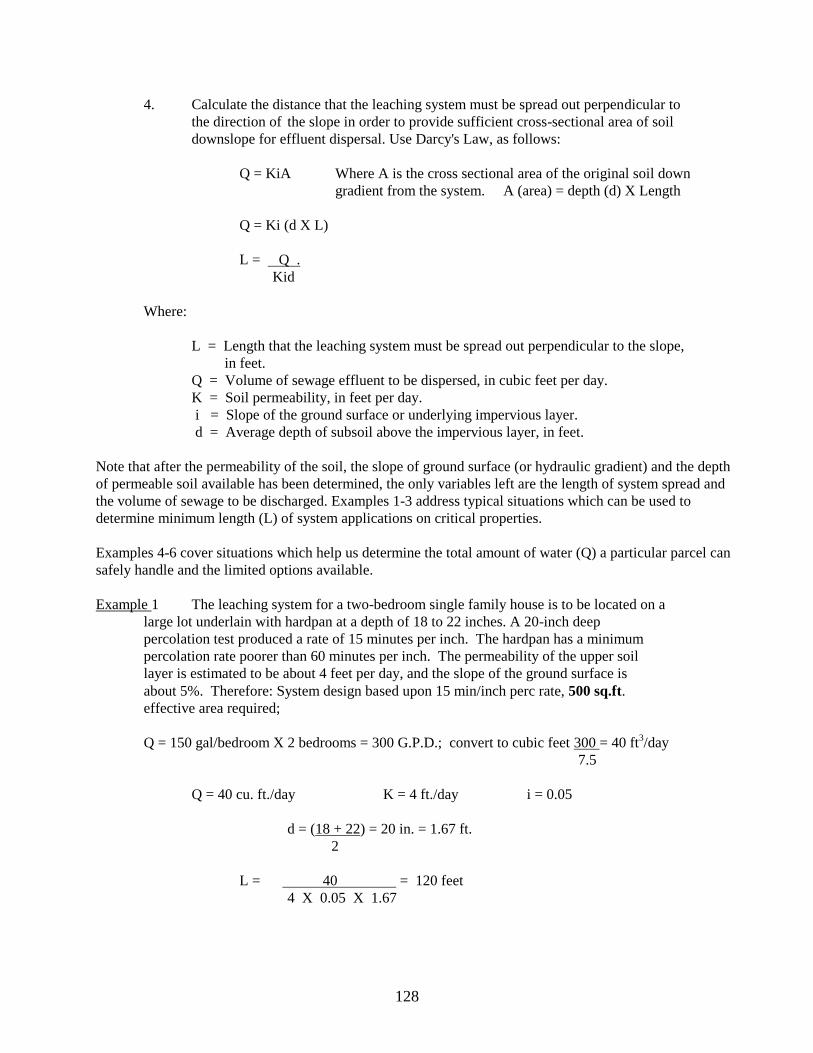
4. Calculate the distance that the leaching system must be spread out perpendicular to
the direction of the slope in order to provide sufficient cross-sectional area of soil
downslope for effluent dispersal. Use Darcy's Law, as follows:
Q = KiA Where A is the cross sectional area of the original soil down
gradient from the system. A (area) = depth (d) X Length
Q = Ki (d X L)
L = Q .
Kid
Where:
L = Length that the leaching system must be spread out perpendicular to the slope,
in feet.
Q = Volume of sewage effluent to be dispersed, in cubic feet per day.
K = Soil permeability, in feet per day.
i = Slope of the ground surface or underlying impervious layer.
d = Average depth of subsoil above the impervious layer, in feet.
Note that after the permeability of the soil, the slope of ground surface (or hydraulic gradient) and the depth
of permeable soil available has been determined, the only variables left are the length of system spread and
the volume of sewage to be discharged. Examples 1-3 address typical situations which can be used to
determine minimum length (L) of system applications on critical properties.
Examples 4-6 cover situations which help us determine the total amount of water (Q) a particular parcel can
safely handle and the limited options available.
Example 1 The leaching system for a two-bedroom single family house is to be located on a
large lot underlain with hardpan at a depth of 18 to 22 inches. A 20-inch deep
percolation test produced a rate of 15 minutes per inch. The hardpan has a minimum
percolation rate poorer than 60 minutes per inch. The permeability of the upper soil
layer is estimated to be about 4 feet per day, and the slope of the ground surface is
about 5%. Therefore: System design based upon 15 min/inch perc rate, 500 sq.ft.
effective area required;
Q = 150 gal/bedroom X 2 bedrooms = 300 G.P.D.; convert to cubic feet 300 = 40 ft3/day
7.5
Q = 40 cu. ft./day K = 4 ft./day i = 0.05
d = (18 + 22) = 20 in. = 1.67 ft.
2
L = 40 = 120 feet
4 X 0.05 X 1.67
129
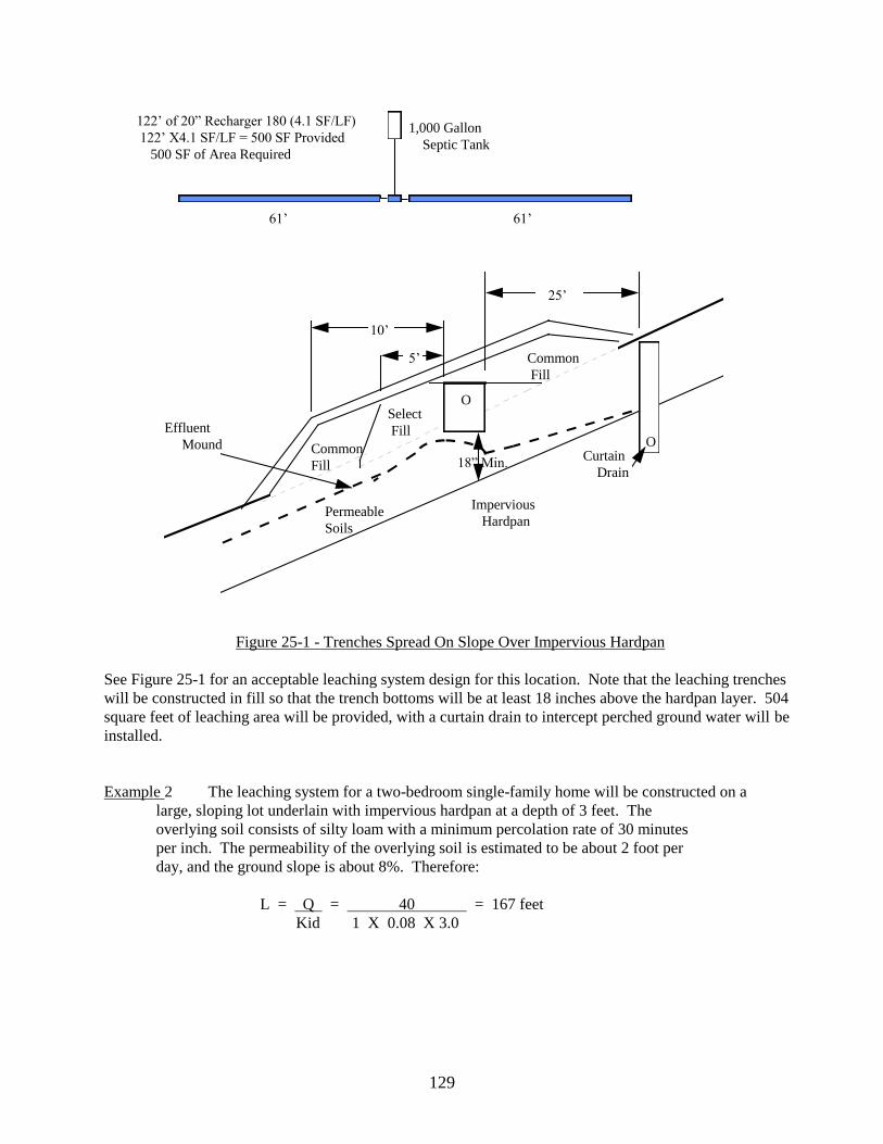
Figure 25-1 - Trenches Spread On Slope Over Impervious Hardpan
See Figure 25-1 for an acceptable leaching system design for this location. Note that the leaching trenches
will be constructed in fill so that the trench bottoms will be at least 18 inches above the hardpan layer. 504
square feet of leaching area will be provided, with a curtain drain to intercept perched ground water will be
installed.
Example 2 The leaching system for a two-bedroom single-family home will be constructed on a
large, sloping lot underlain with impervious hardpan at a depth of 3 feet. The
overlying soil consists of silty loam with a minimum percolation rate of 30 minutes
per inch. The permeability of the overlying soil is estimated to be about 2 foot per
day, and the ground slope is about 8%. Therefore:
L = Q = 40 = 167 feet
Kid 1 X 0.08 X 3.0
O
O
18” Min.
61’ 61’
1,000 Gallon
Septic Tank
122’ of 20” Recharger 180 (4.1 SF/LF)
122’ X4.1 SF/LF = 500 SF Provided
500 SF of Area Required
25’
5’
10’
Common
Fill
Select
Fill
Common
Fill
Effluent
Mound
Permeable
Soils
Impervious
Hardpan
Curtain
Drain

130
Figure 25-2 - Trenches In Slowly Permeable Soil Spread On Slope
See Figure 25-2 for an acceptable leaching system design for this situation. Note that 565 square feet of
leaching trenches will be used, constructed with the invert elevations approximately at original ground
surface. A curtain drain will be installed.
Example 3 The leaching system for a small restaurant with a design flow of 1,500 gallons per
day will be installed in a sloping area underlain by ledge at a depth of 4 to 5 feet.
The soil on top of the ledge consists of sandy loam with a minimum percolation rate
of 5 minutes per inch, and an estimated permeability of about 10 feet per day The
ledge drops about 4 feet in a distance of 100 feet. No ground water was noted on top
of the ledge even during the wet season. Therefore:
Q = 1,500/7.5 = 200 cu. ft./day
L = Q = 200 = 125 feet
Kid 10 X 0.04 X 4
Code requires 1,500 GPD = 1,875 sq. ft. of area
0.8 (application rate)
O
Septic Tank
6 TRENCHES, 56’ LONG, 30” WIDE = 6 X 56 X 2.7 = 907 SQ.FT.
SERIAL DISTRIBUTION
O
O
10 ft. 2’
7 ft.2’
25 ft.
Select Fill
Select Fill
18”
IMPERVIOUS
HARDPAN
Slowly Permeable
Upper Soil
Effluent Mound
8% Slope
Curtain
Drain

131
Design Proposal: 4 rows of 30 inch galleries, each row is 64 feet long. Total effective
leaching area provided: 4 rows X 64’ long X 7.4 sf/lf = 1,894 sq.ft.
which exceeds the 1,875 sq. ft. required.
Figure 25-3 - Galleries Spread On Slope Over Ledge Rock
See Figure 25-3 for an acceptable design for this location. Note that leaching galleries are used, constructed
in fill over the original soil. The size of the leaching system is based on the requirements of the Public
Health Code. No curtain drain is installed. However, the relatively substantial depth of surrounding soil
and fill should be sufficient to store and disperse any seasonal rainfall accumulation.
APPLICATION II - DETERMINING THE MAXIMUM HYDRAULIC CAPACITY SOILS
Quite frequently, engineers and health department staff must be able to calculate or estimate the hydraulic
capacity of any given site to determine if proposed development is feasible for particular soil conditions.
This is particularly important for construction of large sewage disposal system or on sites where the soils
are marginal for leaching purposes. Central sewage disposal systems which concentrate discharges in one
or more limited areas may also warrant close evaluation. Proper use of Darcy's Law can be a useful tool in
determining whether proposed development exceeds the soils ability to disperse projected sewage flows or
whether the scope of development should be scaled down within a safe range to assure health and
environmental protection.
64’ 64’
15
15’
10’
4’
High Level Overflow
Select
Fill
Top Soil
Ledge Rock
Effluent
Mound
Permeable
Soil

132
The following is a few examples of situations which local health departments have typically had to analyze:
Example 4 - Feasibility of Proposed Subdivision
A local developer wishes to subdivide a 10.5-acre parcel into 7 lots in accordance with existing zoning
requirements. The property has 1,300 foot frontage along an existing town road and slopes gently away
from the road toward a wetland near the rear property line. The developer would like approval for 6 lots,
each approximately 180 ft. in width by 340 ft. in depth. Considering minimum zoning setback of 50 ft.,
average house width of 30 feet and the required 25 feet set back from building footing drains, a series of
deep test pits were excavated approximately 125 feet from the front property lines to evaluate soil, water
and ledge conditions.
Evaluation of the soils confirms the presence of Paxton soils, S.C.S. classification of PbB with
approximately 8% slope. Subdivision plans submitted to the health department for review and comment
show a series of 4-bedroom homes, all with wells located in the front yards and rear yard leaching areas
spread out 100 feet parallel to the contours. Due to the compact till observed 32 inches below grade, it is
reasonable to assume each system will be placed in select fill (once top soil is removed) and a curtain drain
installed upgrade to intercept ground water. Percolation rates were found to be between 31 to 45 minutes
per inch. The Planning and Zoning Commission wants to know if this subdivision should be approved.
Without requiring extensive permeability testing or ground water monitoring, how can Darcy's Law and
available sources of information be used to assist you in preparing a response?
First, MLSS calculations can be very useful in the initial configuration of the subdivision lots. The spread
required by MLSS can be “blocked” out on each lot to indicate the necessary size and spread of a typical
leaching system. In this example the spread required for the system would equal:
MLSS = HF X FF X PF = 26 X 2.0 X 3.0 = 156 feet
Therefore, if each of the proposed lots provided the required amount of primary and reserve leaching areas
and were spread a minimum of 156 feet along ground contours the lots could be approved.
A further analysis to confirm the above results would employee direct use of Darcy’s Law:
GIVEN: (1) 4 bedroom houses x 150 gal/room = 600 GPD/7.5 = 80 cubic feet/day
(2) Paxton soils in SCS book have permeability’s which range as follows
0-8” 0.6-2.0 inches/hr = 1.2-4.0 ft/day
8"-32" 0.6-2.0 inches/hr = 1.2-4.0 ft/day
32"-60" 0.06-0.2 inches/hr = .12-0.4 ft/day
(3) Width of system application 180’ lot - 10' each property line - +160 ft
(4) Gradient = 8% or .08
(6) Depth of permeable soil = 32"
ASSUME: (1) K = average of SCS range 1.2 + 4.0 = 5.2/2 = 2.6 ft/day
(2) Curtain drain will cut off all inflow from up slope watershed
(3) L = 160’ parallel to contours

133
Solve for Q, the quantity of water each lot can handle:
Q = KiA = Ki(L x d)
Q = 2.6 X 0.08 X (160 x 32/12)
Q = 88.8 cubic feet
With the potential for generation of 80 cubic feet of sewage and capacity to handle over 88 cubic feet, it is
evident that the lot can support a system for a 4 bedroom home, both in terms of MLSS criteria and Darcy’s
Law.
However, if the developer wanted to increase the number of lots on the subdivision by reducing the width of
the property (relative to the contours), hydraulic constraints would quickly become evident. If the width of
the lots were reduced to 150 feet across (meaning the maximum amount of system spread would be reduced
to 130 feet) then the required spread of 156 feet determined by MLSS would not be available. The
developer would than have to reduce the number of bedrooms allowed for each home to three (3) in order to
meet MLSS requirements:
MLSS = HF X FF PF = 26 X 1.5 X 3.0 = 117 feet
Under Darcy’s Law:
A three (3) bedroom home will generate:
Q = 150 GPD X 3 Bedrooms / 7.5 gallons per cu.ft. = 60 cu.ft.
The proposed lot will support:
Q = KiA = Ki (L X d) = 2.6 X 0.08 X (130 X 2.66) = 71.9 cu ft.
Therefore, a three (3) bedroom home would be acceptable.
It is reasonable to recommend that development of the proposed subdivision of 3 or 4 bedroom homes will
be dependent on the proposed width of the lots. If the above MLSS type analysis indicates that a lot can not
meet requirements of Public Health Code Section 19-13-B103e.(a)(4.), which specifically prohibits the
issuance of permits on any property where the surrounding naturally occurring soil cannot adequately
absorb or disperse the expected volume of sewage effluent without overflow, breakout or detrimental effect
on ground or surface water , approval of that subdivision lot should not be granted. It would be advisable to
discuss your comments with the design engineer prior to preparing a response to local commissions to
determine if additional tests should be made to confirm soil permeability’s and method of analysis which
may alter the status of the lot..
Example 5 - The Motel/Restaurant Proposal
A local business man owns a 1.8 acre parcel at the intersection of two busy state highways. He would like to
construct a two story 30 room motel and a 50 seat restaurant on this parcel which is 280' wide by 280 feet in
depth. The view from the highway shows the land sloping from the left to the right at approximately 12%
grade. In order to meet all zoning requirements, preliminary site plans designate a leaching area in the rear
right corner approximately 190 feet wide (parallel with contours) by 70 feet in depth. Soil tests reveal the

134
presence of Charlton soils, SCS classification CfC with a restrictive compact soil noted 4.5 feet below
existing grade. Can this site handle the proposed development?
GIVEN: (1) 30 room motel @ 100 gal/room = 3000 GPD
50 seat restaurant x 3 turnovers x 10 gal = 1500 GPD
Total 4500 GPD/7.5 = 600 cubic ft.
(2) Charlton soils in SCS book have permeabilities which range as follows:
0-6" - 0.6-6.0 inches/hr = 1.2-12 ft/day
6-26" - 0.6-6.0 inches/hr = 1.2-12 ft/day
26-60" - 0.6-6.0 inches/hr = 1.2-12 ft/day
(3) Percolation Rate = 4 minutes/inch
(4) Width of application area 190 feet
(5) Gradient s 12% = .12
(6) Depth of permeable soil = 4.5 ft. to restrictive layer, no groundwater
observed or anticipated
(7) Tube samples (minimum of 6 tubes) confirm average K values of 6.2 ft/day.
Determine whether this site can handle projected flows:
Utilizing MLSS Criteria:
MLSS = HF X FF X PF = 14 X 4500/300 X 1.0 = 210 feet of spread required.
Utilizing Darcy’s Law:
This analysis will be based on the actual permeabilities from the tube samples
and the actual length of application (190’) available on this site.
Q = KiA = Ki (LXd)
Q = 6.2 x .12 x 190 x 4.5
Q = 636 cubic feet/day
Q = 636 cu.ft./day X 7.48 gal./cu.ft. = 4,757 gallons per day can be
discharged into the naturally occurring soils without becoming
completely saturated.
As this example illustrates, the MLSS calculations may be more restrictive in some cases, especially when
dealing with fast soils, than Darcy’s Law. MLSS indicated that 210 feet of spread would be required in
order to adequately disperse the 4,500 gallons of daily discharge. Since the site can provide only 190 feet
of spread, MLSS would deem it unacceptable for the proposed usage. However, when a more in-depth
hydraulic analysis was performed, utilizing actual permeabilities and Darcy’s Law, it was found that the
190 feet of actual spread available would be sufficient for the proposed usage.
Special Note: The placement of the system in terms of elevation should be of concern in the above
example, since the hydraulic mound created beneath a fully utilized system will likely saturate almost all of
the underlying naturally occurring soils. Therefore it would be detrimental to the performance of the
system if the system was placed into the natural soils and become flooded whenever the system is used at
peak flow. Therefore, designing a leaching system 18” above maximum ground water (the minimum
135
separation required by code) may not be appropriate when the system does not have extra hydraulic relief
built in (significantly more spread than what is required by MLSS or Darcy’s Law).
Consideration for “reserve hydraulic capacity” must also be considered when designing a leaching system.
For the primary system adding “spread” to a system increases the safety factor for proper performance of
the system by providing additional hydraulic window (access to additional unsaturated soils beneath the
system) to accept those “above peak” discharges which may occur from time to time (during house parties
or temporary increases in house occupancy). Another reason for providing extra hydraulic capacity,
especially for the reserve area, is to allow the owners of the home or building to increase usages in the
future. Under present health codes, house additions can be approved when the lot the building is located on
can support a septic system, based on the ultimate configuration of the building, which will meet all health
code requirements (including MLSS). If the total number of bedrooms or design flow increases, no
approval may be given for a building addition, unless hydraulic capacity (MLSS/Darcy’s Law) is
established.
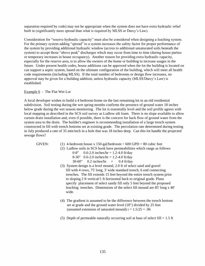
Example 6 - The Flat Wet Lot
A local developer wishes to build a 4 bedroom home on the last remaining lot in an old residential
subdivision. Soil testing during the wet spring months confirms the presence of ground water 18 inches
below grade during the wet season monitoring. The lot is essentially level and the soil profile agrees with
local mapping as described in the SCS soil survey as Ludlow silt loam. There is no slope available to allow
curtain drain installation and, even if possible, there is the concern for back flow of ground water from the
system area to the drain. The builder's engineer is recommending installation of a large trench system
constructed in fill with trench bottoms set at existing grade. The percolation rate determined during testing
in July produced a rate of 35 min/inch in a hole that was 18 inches deep. Can this lot handle the projected
sewage flows?
GIVEN: (1) 4-bedroom house x 150-gal/bedroom = 600 GPD = 80 cubic feet
(2) Ludlow soils in SCS book have permeabilities which range as follows
0-8" 0.6-2.0 inches/hr = 1.2-4.0 ft/day
8-30" 0.6-2.0 inches/hr = 1.2-4.0 ft/day
30-60" 0.2 inches/hr = 0.4 ft/day
(3) System design is a level mound, 2.0 ft of select sand and gravel
fill with 4 rows, 75' long, 3' wide standard trench, 6 end connecting
trenches. The fill extends 15 feet beyond the entire trench system prior
to sloping 2 ft vertical/1 ft horizontal back to original grade. Plans
specify placement of select sandy fill only 5 feet beyond the proposed
leaching trenches. Dimensions of the select fill mound are 85' long x 40'
wide.
(4) The gradient is assumed to be the difference between the trench bottom
set at grade and the ground water level (18") divided by 25 feet
(assumed extension of saturated mound) i = 1.5/25 = .06
(5) Depth of permeable naturally occurring soil at base of select fill = 1.5 ft

136
ASSUME: (1) K = average of SCS range 1.2 + 4.0/2 = 2.6 ft/day
(2) A (application area) = length of application to both sides of system plus
connected ends = (75’ + 75’ + 30’ + 30’) X 1.5’ depth = 315 sq.ft.
Utilizing MLSS Criteria
MLSS = HF X FF X PF = 42 X 2.0 X 3.0 = 252 feet required
Provided = 75’ + 75’ + 30’ + 30’ = 210 feet provided
Figure 25-4 - Flat Lot System with Radial Flow
Utilizing Darcy’s Law
Q = KiA
Q = 2.6 x .06 x 315
Q = 49.1 cubic ft/day
As you can see, the calculations indicate a 4 bedroom home could not be approved if the assumptions made
above were shown to be correct. Field testing to accurately determine permeability would be warranted if
the builder wanted to pursue the 4 bedroom home approval. Further analysis of the above example brings
out a key element of MLSS versus Darcy’s Law, namely there are going to be situations where MLSS
criteria will be met when a Darcy’s Law analysis fails. If the above builder
30’ 30’
75’
75’
sewage flow away from system

137
decides to reduce the number of bedrooms in the proposed house to three (3) the MLSS equation will
change to:
MLSS = 42 X 1.5 X 3.0 = 189 feet required < 210 feet provided
(This assumes the size of the system will not be reduced to a 3 bedroom)
Therefore, approved by MLSS
However, Darcy’s Law indicates only 49.1 cu. ft. (368 gallons) of flow can be absorbed daily, which is
below the design rate for a three (3) bedroom home of 60 cu. ft. (450 gallons).
Under the current Technical Standards the three (3) bedroom home would be approved for the above
example even though Darcy’s Law did not confirm result. The factor tables used for MLSS have this
anomaly built in since the empirical data of years of existing leaching systems performing adequately
does not warrant spreading the systems out any further.
It should be noted that if the ends of the above level leaching system where not tied in then the 60 feet
of “side” lengths (30 feet to each side) could not be granted.

138
26. FIELD EXAMINATION OF SOILS
Soil Feeling and Appearance
Class Dry Soil Moist Soil
Sand Loose, single grains which Squeezed in the hand, it forms
feel gritty. Squeezed in the a cast which crumbles when
hand, the soil mass falls touched. Does not form a rib-
apart when the bon between thumb and fore-
pressure is released. finger.
Sandy Loam Aggregates easily crushed; Forms a cast which bears
very faint velvety feeling careful handling without
initially but with continued breaking. Does not form a
rubbing the gritty feeling ribbon between thumb and
of sand soon dominates. forefinger.
Loam Aggregates are crushed under Cast can be handled quite
moderate pressure; clods can freely without breaking.
be quite firm. When pulverized, Very slight tendency to ribbon
loam has velvety feel that be- between thumb and forefinger.
comes gritty with continued Rubbed surface is rough.
rubbing. Casts bear careful is rough.
handling.
Silt Loam Aggregates are firm but may be Cast can be freely handled with-
crushed under moderate pressure. out breaking. Slight tendency
Clods are firm to hard. Smooth, to ribbon between thumb and
hard. Smooth, flour-like feel dom- forefinger. Rubbed surface has a
inates when soil is pulverized. broken or rippled appearance.
Clay Loam Very firm aggregates and hard Cast can bear much handling
clods that strongly resist crush- without breaking. Pinched bet-
ing by hand. When pulverized, ween the thumb and forefinger,
the soil takes on a somewhat it forms a ribbon whose surface
gritty feeling due to the harsh- tends to feel slightly gritty when
ness of the very small aggre- dampened and ribbed. Soil is
gates which persist. plastic, sticky and puddles easily.
Clay Aggregates are hard; clods Casts can bear considerable
are extremely hard and handling without breaking.
strongly resist crushing by Forms a flexible ribbon
hand. When pulverized, it between thumb and forefinger
has a grit-like texture due and retains its plasticity
to the harshness of numerous when elongated. Rubbed
very small aggregates which surface has a very smooth,
persist. satin feeling. Sticky when
wet and easily puddled. _

139
27. IDENTIFYING SEWAGE POLLUTION IN GROUND AND SURFACE WATERS
Local health departments frequently receive complaints of alleged ground or surface water pollution by
subsurface sewage disposal systems. Investigation often will reveal direct sewage discharges or
overflowing sewage disposal systems in the area. But in some cases, no sources of pollution are evident
and the occurrence of pollution is questionable. Such cases are difficult to resolve to the satisfaction of the
complainant and may require laboratory testing of water samples or dye testing of suspected pollution
sources. In general, however, sampling of ground and surface water should be avoided in the absence of
some indication of possible sewage pollution and no sample should be collected until as much information
as possible is obtained relative to potential sources of pollution. If samples are collected, care must be used
not to request laboratory tests which are costly and unnecessary. Judgment is necessary in interpreting the
laboratory results and in general, no tests should be required unless the results can be properly interpreted
by the collector. It also is necessary to have an understanding of the techniques on limitations of dye testing
before any such program is undertaken.
IDENTIFYING SEWAGE POLLUTION IN WELLS
The sanitary quality of ground water is of concern mainly in connection of possible pollution of wells or
springs. Sewage pollution in wells can be identified fairly conclusively by laboratory analysis, since ground
water should contain little or no bacteria or organic chemicals. Wells may be suspected of being polluted if
the water shows objectionable taste, odor or physical appearance, or if there is a history of illness which
may be water related. In such a situation a water sample should be collected for complete physical,
chemical and bacterial analysis. There also may be wells where the sanitary quality of the water is suspect
because the separating distance from a nearby sewage disposal system does not meet Code requirements.
As long as there is no physical indication of pollution or history of illness, samples should be collected for
bacterial examination only. Wells polluted by sewage would be expected to contain coliform bacteria well
in excess of 2 per 100 ml as measured by the membrane filter test. Nitrogen constituents also are likely to
be high. Nitrate nitrogen would probably exceed 1.0 mg/1, although this in itself may not indicate sewage
since there are other sources of nitrates in ground water such as fertilizers. Any significant amount of
nitrite nitrogen (0.01 mg/1 or greater) may indicate more direct sewage pollution because nitrites are rapidly
oxidized to nitrates by percolation through soil. Organic (albuminoid) nitrogen and ammonia nitrogen are
constituents of fresh sewage and should only be found in highly polluted wells. However, they may also be
due to the presence of other organic matter such as leaves, insects, dirt or debris which has somehow
entered the well. Except for coastal areas, ground waters in Connecticut are generally low in chloride
content. Therefore, chloride levels exceeding about 15 mg/1 may also indicate sewage pollution. It should
be noted that wells and springs producing water of good overall sanitary quality may occasionally contain
low levels of coliform bacteria. This probably results from chance contamination by surface water draining
into the well aquifer, or by contamination in the storage or piping system. Disinfection and resampling
should produce good bacterial results. Repeated bacterial contamination without confirming chemical
pollution or nearby sources of sewage pollution probably indicates that the well is poorly sealed or
protected.
IDENTIFYING GROUND WATER POLLUTION
Other than where wells are concerned, the effect of subsurface sewage disposal systems on ground water is
rarely a public health concern. It can be assumed that the ground water table in the immediate area of such
a system is polluted to some extent. Such a level of pollution is acceptable from the standpoint of public
health and this is the reason for the separating distances required by the Public Health Code. Unacceptable

140
ground water pollution occurs when the dissolved oxygen which is normally present in ground water is
depleted by high levels of organic pollutants. When this occurs, the physical and chemical characteristics
of the ground water can change significantly. The ground water can become odorous if sulfates, which may
be present in the waste or in the soil, are chemically reduced to hydrogen sulfite. Iron, which is common in
Connecticut soils, probably will be dissolved by the oxygen deficient ground water and may be deposited as
an orange sludge where polluted ground water leaches to the surface. Blackish sludge deposits may also
occur in some areas due to manganese leaching. Ground water pollution can be greatly aggravated by the
action of certain bacteria which can thrive in ground water which is rich in iron or manganese and organic
nutrients, and is deficient in dissolved oxygen.
Subsurface sewage disposal systems which have been properly designed and installed in accordance with
the Code requirements should not cause an unacceptable level of ground water pollution. Most cases of
ground water pollution are caused by the burial of large volumes of organic material, such as municipal
refuse, demolition material, agricultural waste or swamp muck. However, an unusually large subsurface
sewage disposal system installed in an area of highly permeable soil may cause ground water pollution,
particularly if the ground water table is high. The same may occur from smaller systems if Code
requirements are not followed. It should be noted that ground water pollution from sewage is more likely to
occur in permeable soils than in poor soils and sewage disposal system failure or overflow is rare in such
situations.
Often there is little that can be done to correct an existing ground water pollution problem since it is not
possible to change soil conditions or to reduce the volume of sewage discharged to the ground water. The
main thing that the investigator should do is to determine whether observed nuisance conditions result from
ground water pollution or from direct sewage discharge from unknown sources. This can only be
determined by sanitary survey, including dye testing if necessary. Other potential sources of ground water
pollution, such as sanitary land fills, etc., should not be over looked when making the survey. Depending
on the findings, conclusions can be made as to the public health significance and possible long range
solutions. This may include such things as extension of public sewers or public water supply mains,
rezoning, or ground or surface water drainage projects which would alleviate the nuisance conditions.
IDENTIFYING SEWAGE POLLUTION IN SURFACE WATERS
It is difficult to identify sewage pollution in surface waters by laboratory analysis because of the great
variations in naturally occurring levels of both bacteria and organic chemicals in such waters. In some
cases, there may be relatively high levels of the type of bacterial or chemical pollutants which are normally
found in sewage, without any sewage actually being present. In other cases, sewage may be entering
surface waters without producing unusually high pollutant levels because of high dilution. For these
reasons, a program of sanitary survey, supplemented by dye testing if necessary, should be used where
surface water pollution is suspected. Water samples should only be used to confirm or supplement sanitary
survey information, although samples are frequently collected to satisfy public demand for information
about the sanitary quality of a particular body of surface water.
If samples are collected from a surface water, only bacterial analysis should be requested. Information
should be provided as to the expected bacterial quality of the water since this will determine the testing
methods and sample dilution’s used in the laboratory. Chemical testing is not recommended because there
is little if any relationship between chemical constituents and sanitary quality in most surface waters.

141
The standard test for bacterial quality of surface water is the total coliform determination. The test is based
on determination of the quantity of a particular type of bacteria in a given volume of water samples. Since
this type of bacteria is naturally found in the intestinal tract of humans and warm blooded animals, its
presence in water is taken as being indicative of the presence of sewage in the water and the quantity of the
organism present is taken as being indicative of the degree of sewage pollution. Unfortunately this is not
entirely true because naturally occurring coliform organisms are also found to be present in varying
amounts in all surface waters. Coliform organisms are found in soils, muds and decaying vegetation. Large
numbers of such organisms are discharged by animals and surface runoff from pastures normally is high in
coliforms. There are other bacterial tests which are possibly more valid indicators of sanitary quality. The
most important of these is the fecal coliform test which is a modified total coliform test. In this modified
test, a new medium is utilized and an elevated incubation temperature is used to distinguish the fecal
coliforms from the total coliforms. While this technique may offer some advantages, it is subject to the
same general criticism as the total coliform test. A disadvantage of this test is that the uninformed public
has a tendency to conclude that the presence of any fecal coliforms indicates human sewage pollution which
may not be the case. In general, fecal coliform tests are not recommended except in certain situations where
the total coliform test appears to be giving misleading high results. In such situations, both tests are run on
the samples and if the fecal coliform content is much lower than the total coliform content, it is assumed
that the bacteria are not due to sewage.
EFFECT OF RUNOFF ON BACTERIAL QUALITY OF SURFACE WATERS
The Connecticut Department of Health Services, in cooperation with various local health departments, has
done extensive monitoring of surface waters. This monitoring has shown a very distinct relationship
between the bacterial quality as indicated by the total coliform content and the amount of surface water
runoff at the time of sample collection. Experience has shown naturally high coliform contents in streams,
ponds and even small lakes after a rainfall, even where there is no known source of sewage pollution on the
watershed. Such elevated counts are concluded to be due to naturally occurring coliforms and are not a true
indication of pollution. Water washing over the surface of the ground after a rainfall will pick up naturally
occurring coliforms and carry them into streams, rivers and lakes. For this reason, the total coliform
content of a surface water will reflect the amount of surface runoff in it as well as the degree of sewage
pollution. Therefore, the total coliform content of a running stream or river will always be higher than that
of a large pond or lake since the percentage of surface wash is higher, particularly after a rain when the
runoff is high. Coliform organisms will naturally tie out with time in clear water with low organic content.
This characteristic also contributes to the lower coliform levels in large ponds and lakes where the storage
time of the surface water runoff is great.
Experience in Connecticut has shown that inland lakes with relatively clean watersheds should show
coliform counts under 200 per 100 ml. On the other hand, the coliform content in a running stream is rarely
under this figure and a coliform content of 1000 per 100 ml or less is considered an indication of good
sanitary quality, suitable for bathing purposes. The same streams may show counts of up to 10,000
coliforms per 100 ml following a heavy rain due to coliforms from natural sources without indicating
sewage pollution. Counts of over 10,000 per 100 ml indicate probable sewage pollution. It is evident,
therefore, that considerable judgment must be used when interpreting the results of bacterial samples
collected from surface waters. Water samples should not be collected after a heavy rain- or when the water
is noted to be turbid due to heavy runoff. Sanitary quality judgment should be made only after review of the
results of the number of samples taken over a period of time under various conditions, together with a
sanitary survey of the watershed for possible sources of pollution. when a number of tests results are
available, the median figure should be used as the determining value rather than the average, which may be
distorted by a few high sample results. Samples should be collected by dipping under the water surface

142
where the water is sufficiently deep so that no mud or silt will be stirred up and collected in the sample
bottle.
DYE TESTING
Dye testing of sewage collection and disposal systems may be done for any of the following purposes.
1. To find the source of an obvious sewage discharge when it is not apparent.
2. To establish evidence of sewage overflow or discharge in preparation for legal action.
3. To locate illegal sewage connections to storm sewers.
4. To determine if a subsurface sewage disposal system periodically overflows to ground
surface or leaks into a ground or surface water drain.
5. To determine if a water discharge contains sewage.
The water soluble dyes used for these purposes are detectable in very dilute solution. Therefore, the dye is
relatively easy to see in water discharges, catch basins, streams and pools of standing water. Most of these
dyes are adsorbed to some degree by various minerals in the soil. For this reason, dye may be removed by
percolation through even a few feet of soil and is reliable only as an indicator of more or less direct
pollution. Failure to recover dye in a well or ground water does not necessarily indicate that there is no
sewage pollution.
Fluorescein dye is normally used for testing subsurface sewage disposal systems since it is less readily
absorbed by soils than most other dyes. It is usually used in the form of a sodium salt called uranine, a
reddish powder rapidly soluble in water. Normally, a tablespoon of this powder is placed in the toilet
bowl and flushed into the sewage disposal system in question. The dye will not stain sanitary fixtures
but must be handled carefully to avoid spilling since even a few crystals will stain clothes, floors and
furniture. When diluted, fluorescein has a greenish-yellow color which is fluorescent under ultraviolet
light. Fluorescein can be detected in dilute concentrations invisible to the naked eye by means of a
laboratory fluorometer. It also can be measured in dilute concentrations in the laboratory by acid
extraction techniques.
Rhodamine dyes also may be used as sewage tracers. These come in liquid solution, are also
fluorescent, and are available in several colors. The more widely used dyes of this type are Rhodamine
B which is red, and Sulpho Rhodamine Pink B which has a brilliant pink color. Rhodamine dyes are
generally more stable in sunlight than fluorescent and, for this reason, they are frequently used for
streamflow measurement. They are more readily absorbed by soil than fluorescent and therefore are less
suitable for testing subsurface sewage disposal systems. The variety of available colors allows several
such systems to be tested at the same time, thereby expediting dye testing programs involving a large
number of systems.

143
When dye testing a subsurface sewage disposal system, it should be understood that the dye may not
immediately show up at the suspected point of discharge. The sewage may first pass through a septic tank
or leaching system which will delay the appearance of the dye for one or two days. Therefore it is
necessary to periodically reinspect such systems over several days after using the dye before it can be
concluded that the system is functioning properly. Dyes are generally unaffected by chemicals normally
found in domestic sewage with the possible exception of chlorine bleach. Before using dye, a brief
inspection should be made of the plumbing system. It may be found that there is more than one waste line
leaving the building. In such a case, each system should be tested separately with dye Frequently
basement washing machines are discharged into cellar trains and can easily be overlooked when dye
testing for pollution sources.

144
28. NON-CONVENTIONAL TOILET SYSTEMS
From time to time, local or state officials are requested to review various proposals for the installation of
non-conventional toilet systems. Technical Standard IX describes several types of non-discharging toilet
systems which are acceptable for certain uses. Public Health Code regulation 19-13-B103f describes the
conditions under which these systems may be approved. In all cases, approval must be granted by the local
director of health before such systems can be used and in some cases approval also is necessary from the
State Department of Public Health. This section of the Public Health Code also allows the State
Department of Public Health to grant an exception to allow one of these toilet systems or another type not
specifically included in the Technical Standards to be used in a particular instance upon a determination
that the system will provide for proper disposal and treatment of toilet wastes or gray water.
Non-conventional toilet systems are most commonly used in the repair of failing subsurface sewage
disposal systems on marginal lots where it is necessary to reduce the volume of sewage discharge to the
leaching system in order to allow it to function properly. Most regulatory officials are reluctant to approve
non-conventional toilet systems for other purposes because acceptance of such toilets by the public is
generally poor. High operating costs, increased maintenance and objectionable aesthetic conditions are
common with most non-conventional toilet systems. Many users will desire to convert to conventional
water carriage flush toilets after a period of time. For this reason, application for approval of non-
conventional toilet systems should come from the property owner and individual who will use the system,
not from the builder or developer. Application for installation of a non-conventional toilet system in no
way eliminates the need to test the lot as to its suitability for subsurface sewage disposal since a gray water
disposal system will be necessary in almost all cases. Property owners should seek the advice of an
experienced engineer or installer, as well as the local Sanitarian, before making any final decision on using
a non-conventional toilet system. If a non-conventional toilet system is approved on a lot which is
unsuitable for sewage disposal from conventional flush toilets, this fact should be noted on the permit. It
would also be desirable to record this on town land records to alert prospective buyers as to limitations on
toilet and sewage disposal systems.
Table 28-1 provides a brief description and summary of pertinent information concerning many of the toilet
and treatment systems discussed. Selection of a nonconventional toilet system depends on the desires
reduction in sewage volume, the availability of utilities such as water and electricity and the expected
usage. It should be kept in mint that all residential buildings and most non-residential buildings will
generate liquid wastes from sinks, tubs, showers etc. which will require a conventional subsurface sewage
disposal system.
LOW VOLUME FLUSH TOILETS
Specially designed or modified toilet fixtures which use a reduced volume of water for flushing purposes
are the type of non-conventional toilet systems which are most acceptable to the user and are the most
widely used. Devices are available which can be used to modify conventional water closets and reduce
flush volume. Such devices generally are inexpensive and can be installed by the homeowner. In general,
no approvals are required from health or building officials for making such modifications. Tank inserts
reduce the volume of flush water stores in the tank while utilizing the same flush valve. New valves can
be installed in most existing tanks which will allow the flush to be regulated for larger or smaller volume,
depending on what is required. Such modifications of existing toilets may reduce the volume of toilet
wastes by up to 50%. Specially designed gravity operated toilets also are available which will reduce
waste volume even more. Most of these use a high velocity discharge from an elevated storage tank to

145
clear wastes from a hydraulically modified toilet bowl with a relatively small volume of water. Such
special toilets use 1 to 2 gallons per flush and are similar in appearance and operation to conventional
toilets. However, more frequent cleaning of the bowl may be required. Installation may be made by a
plumber and little modification to the existing house plumbing is required.
COMPRESSED AIR/VACUUM TOILETS
Toilet systems which utilize compressed air or vacuum provide greater reduction in effluent flows
generated. Some systems use as little as 1 pint per flush and provide acceptable bowl evacuation. Because
of the high initial cost involved with installation of air pressure or vacuum systems, their use is usually
restricted to commercial or manufacturing facilities which can incorporate the cost of installation and
maintenance as part of their operational budget. Portable toilet facilities which utilize compressed air or
vacuum have been leased by the State Department of Environmental Protection for use in state parks.
Their function was deemed adequate for the required short period of service and they may be well suited
for mass gatherings or public events. However, electrical service must be available.
COMPOSTING TOILETS
Composting toilets have no liquid discharge of any kind. There is a small volume of composted solid
material which must be periodically removed. This waste is likely to contain pathogenic organisms and
should be disposed of by burial or land filling. Large volume composting units allow a relatively long
time period for the composting action. There is little regulation of moisture or temperature within the
unit and composting action may be slow or irregular. They may be used where water or electricity is not
available, but an electrical ventilation fan is desirable to control odors and reduce moisture buildup
within the unit. Installation of a large composting toilet within an existing house may require removal of
exterior or interior walls in order to accommodate the large chamber. Excessive liquid accumulation has
been a problem where large composting chambers are located outside or in an unheated basement or
enclosure. Heat assisted composting toilets are equipped with electrical heating units and ventilation
fans which may be regulated to provide optimum conditions for composting action. The relatively small
size of the units allows them to be placed within existing rooms. However, experience has shown that
most users are unable to properly regulate the composting action. Compost dehydration and odor is
common in such small composting units. Most manufacturers recommend that heat assisted compost
toilets not be used for more than 2 or 3 persons on a continuous basis.
Successful operation of both large capacity and heat assisted composting toilets is closely related to the
habits of the users and their care and understanding of the composting process. Moisture must be
controlled by adding solid material or regulating ventilation or temperature. Changes in these conditions
or in patterns of use may cause problems. Insect breeding or mold growth can create nuisances.
Composting toilets are allowed in Connecticut only for abatement purposes, for replacing existing
privies, or for new buildings on lots which have been tested and found to be satisfactory for a
conventional subsurface sewage disposal system.

146
INCINERATION TOILETS
Incineration toilets also have no liquid discharge. They are rarely used in residential buildings but may be
installed to provide toilet facilities in lightly used non-residential buildings such as warehouses or electric
substations, where no water supply is available. Incineration toilets require electrical power to operate a
blower, and electricity, gas or oil to generate the temperature required for combustion. Installation and
operating costs are relatively high and their use has been declining in recent years. Odors may be a problem
in built-up locations, particularly with the electric burning units which require a longer period of time to
reach proper combustion temperatures. It also may be difficult to keep the toilet bowl clean since there is
no rinse action. Incineration toilets are not suitable for public toilets or for any kind of heavy use because of
the burning time required between uses.
CHEMICAL FLUSH TOILETS
Chemical flush toilets do not discharge to a subsurface sewage disposal system. Instead, the chemical
solution used for flushing purposes is recycled. Most such toilets use a water solution containing
deodorizing chemicals which may be hazardous if discharged to the ground waters. This liquid must be
periodically removed and disposed of off-site. Chemical flush toilets cannot be located within residential
buildings or human habitations, except with special approval by the State Department of Public Health.
This is mainly to assure adequate venting of chemical odors and to facilitate periodic removal of the
chemical solution. Chemical flush toilets normally are located in freestanding toilet buildings or vehicles.
The chemical flushing solution is stored in a holding tank within the toilet building or vehicle. Spent
solution may be periodically discharged to a larger holding tank located nearby. It should not be discharged
into a leaching system.
An oil recycling flush toilet system is somewhat different, inasmuch as the chemical used for flushing
purposes does not have to be periodically removed. An odorless mineral oil is used for flushing and
transporting waste to a sealed separation tank. The mineral oil floats to the top of the tank, is separated and
recycled. The solid and liquid wastes remain in the bottom of the separation tank and must be periodically
removed. This waste is biodegradable, but it is extremely concentrated and may be contaminated with oil.
It should be taken to a septage disposal area rather than discharged to a subsurface sewage disposal system.
This type of chemical flush toilet can be located within a human habitation with approval by the State
Department of Public Health. However, installation and operation costs are extremely high since a
completely separate plumbing system is required. All recycling toilets probably are practical only for
commercial buildings or separate toilet buildings.
TREATMENT AND RECYCLING TOILET SYSTEMS
Some technologically advanced systems are available which can treat and recycle water-flushed toilet
wastes without the addition of chemicals. Toilet wastes are pumped to a series of packaged treatment
modules which aerate, filter and disinfect the waste prior to recycling. No toxic chemicals are added since
treatment is largely by a biological means. Solids are broken up, digested and recirculated. Only a small
volume of liquid is periodically withdrawn from the close system and replaced with water. Such complete
treatment and recycling toilet systems are very expensive to install and operate and probably only suitable
for commercial buildings where operating costs can be included as part of the normal cost of doing
business. Treatment facilities should be placed in a separate room if they are located within a human
habitation. Special approval may be granted by the State Department of Public Health for treatment and
recycling toilet systems. However, site conditions would have to be unusual for such a system to be
considered. Engineers' plans would be required.

147
TABLE 28-1 - NON-CONVENTIONAL TOILET SYSTEMS
Operation and Total Flow
Generic Type Description Considerations Maintenance Reduction %
Toilet with Displacement devices Device must be Post-installation 4-8
Tank Inserts placed into storage compatible with and periodic
tank of conventional existing toilet inspections to
toilets to reduce and not interfere insure proper
volume but not height with flush positioning.
of stored water. mechanism.
Varieties: Plastic Installation by
bottles, flexible owner.
panels, drums or
plastic bags.
Dual Flush Devices made for use Device must be Post-installation 6-15
Toilets with conventional compatible with and periodic
flush toilets; enable existing toilet inspections to insure
user to select from and not interfere proper positioning
two or more flush with flush and functioning.
volumes based on mechanism.
solid or liquid waste Installation by
materials. owner.
Varieties: Many
Water-Saving Variation of conven- Interchangeable Essentially the 6-10
Toilets tional flush toilet with conventional same as for a
fixtures; similar in fixture. conventional unit.
appearance and Requires presuriz-
operation. Redesigned ed water supply.
flushing rim and
priming jet to initiate
siphon flush in smaller
trapway with less water.
Varieties: Many manu-
facturers but units similar.
Washdown- Flushing uses only Rough-in for unit Similar to con- 21-27
Flush water, but sub- may be non- ventional toilet,
stantially less standard. but more frequent
due to washdown Drain line slope cleaning possible.
flush. and lateral run
Varieties: Few restrictions.
Requires pressuriz-
ed water supply.
Operation and Total Flow

148
Generic Type Description Considerations Maintenance Reduction %
Pressurized Specially designed Compatible with Similar to con- 14-18
Tank toilet tank to most any con- ventional toilet
pressurize air ventional toilet fixture.
contained in toilet unit.
tank. Upon flushing, Increased noise
the compressed air level.
propels water into Water supply
bowl at increased pressure of 35
velocity. to 120 psi.
Varieties: Few
Compressed Similar in appearance Interchangeable Periodic main- 30
Air-Assisted and user operation to with rough-in for tenance of compressed
Flush conventional toilet; conventional air source.
Toilets specially designed fixture. Power use - 0.002KwH
to utilize compressed Requires source per use.
air to aid in flush- of compressed
ing. air; bottled or
Varieties: Few air compressor.,
need power source.
Vacuum- Similar in appearance Application Periodic main- 30
Assisted and user operation largely for multi- tenance of vacuum
Flush to conventional toilet; unit toilet pump.
specially designed installations. Power use - 0.002KwH
fixture is connected Above floor, rear per use.
to vacuum system discharge.
which assists a small Drain pipe may
volume of water in be horizontal or
flushing. inclined.
Varieties: Several Requires vacuum pump.
Requires power source.
Black Water Similar in appearance Application Periodic main- 40
Treatment and user operation to largely for tenance of all
& Recycling conventional toilet; multi-unit toilet treatment units
waste water aerated, installations. including pumps
filtered, disinfected Requires separate and compressor by
and returned for use closed loop plumb- skilled technicians.
in flushing. ing, room for
Varieties: Few treatment com-
ponents.
Uses air compressor,
pumps, filter and
disinfection units.
Requires power source.

149
Operation and Total Flow
Generic Type Description Considerations Maintenance Reduction %
Gray Water Similar in appearance Application for Periodic main- 40
Treatment and user operation to single-family tenance of filter,
& Recycling conventional toilet; residential. pump and disinfection
wastes from sinks, Requires separate units.
showers and tubs are closed loop plumb-
filtered, disinfected ing.
and returned for use Requires use of
in flushing. filter, pump and
disinfection units.
Requires power source.

150
29 HOLDING TANKS
A holding tank is a large, watertight tank which receives and stores liquid wastes from a building. The tank
is pumped periodically and the waste removed for disposal off the site by a licensed septage hauler.
Pumping such a tank can be quite expensive and for this reason, holding tanks normally should be con-
sidered only as an interim measure until a permanent method of disposal is available. This is particularly
true for residential buildings where per capita water consumption and related pumping costs are high.
Holding tanks may be used as an interim measure while public sewers are under construction or where a
building is scheduled to be abandoned in the near future. Interim holding tanks for residential buildings
probably are not cost effective if the period of use exceeds twelve months, although non residential holding
tanks may be used for longer periods.
There are also situations where the long term use of a holding tank may be considered. A holding tank may
be used to abate an existing sewage problem at a private residence where there is no other alternative.
However, it is extremely important that water usage be reduced as much as possible by the installation of
non-discharging toilet systems, removal of laundry facilities and use of water saving sanitary fixtures.
Failure to do this will result in high pumping costs and may cause the owner to install an illegal overflow or
discharge. Water usage is more easily reduced at a seasonal cottage and holding tanks are more practical
for abatement situations. There are certain commercial and industrial buildings such as warehouses,
garages and equipment buildings for which installation and operation of a holding tank would represent a
relatively small part of the overall operational cost of such a facility and therefore may be a feasible
alternative. Holding tanks are not normally approved for new construction projects.
The holding tank should have sufficient liquid storage capacity to hold the volume of sewage expected to be
discharged from the building over the period of a week or more. Holding tanks should never be designed to
be pumped when full. Instead, the schedule of pumping should be such that the tanks are pumped when
about half full. For instance, if a holding tank is large enough to store one weeks sewage flow, the tank
should be pumped about every three days on a regular schedule. Such an arrangement anticipates that there
will be occasions when the scheduled pumping will be delayed due to reasons beyond the control of the
pumper such as equipment breakdown, illness or adverse weather. There should be a liquid level indicator
or alarm which would readily indicate when the holding tank has reached the level at which it should be
pumped. This would tell the owner of the building that there is a potential for overflow and allow him to
contact the pumper before this occurs. Sometimes two holding tanks are used in series with a high level
alarm sounding when the first tank is full.
Holding tanks should be located in secure areas which are not available to the general public. Holding
tanks must have easily removal manholes extended to grade, which could represent a safety hazard.
Holding tanks should be considered potential sources of pollution and should be located so as to provide the
minimum required separating distances for subsurface sewage disposal systems in the Public Health Code.
In some situations it may be necessary to reduce the required minimum separating distance in order to abate
a sewage problem. If this is allowed, particular care must be given to sealing and testing the holding tank
for leakage and the ground surface around the tank should be paved and graded to carry possible overflow
away from wells, watercourses and residences.
No holding tank should be installed without approval of both the State Department of Public Health and the
local director of health. The owner of the facility must agree to enter into a contract with a licensed

151
subsurface sewage disposal system cleaner for the regular pumping of the tank. The owner of the facility
may be required to furnish the health department a copy of a written contract with
such a cleaner. The cleaner must specify the final disposal area for the waste removed from the holding
tank. If the volume of waste is large, a letter of acceptance may be required from the operator of the
disposal area. The pumping of the holding tank and disposal of the waste should be periodically inspected
by the local health department.
.

152
30. SEWAGE PUMPING STATIONS
Sewage pump stations are sometimes necessary to make use of leaching areas located at higher elevations
than the building served or for dosing large leaching systems when use of a siphon is not feasible. The
sewage pump station consists of a concrete or polyethylene pump chamber, electrical controls, high level
alarms and associated piping. For most installations, liquid discharged from the septic tank enters into the
pump chamber and is stored until the liquid reaches the pump activation level. The pumps then activate and
force sewage through a small diameter pressure pipe to the leaching system.
Section Vl of the Technical Standards specifically requires intermittent dosing through use of siphons or
pumps for large leaching systems with a design flow of 2,000 gallons per day and greater where the total
length of distribution pipe is 600 feet or more. If the property is relatively level or the building sewer exits
the foundation wall at depths which prevent use of a dosing siphon, a pump lift station may be required.
For large sewage disposal systems, dual alternating pumps must be provided. For small sewage disposal
systems with design flows less than 2,000 gallons per day, either duplicate alternating pumps or a single
pump with emergency storage volume in the pump chamber must be provided. Household pump chambers
are usually 1,000 gallon septic tanks which are converted for use as a pump station. High level indicators or
alarms and extension of access manholes to grade are required for all pump lift stations.
When used as dosing mechanisms, pump controls should be set to discharge at least 50% of the volume of
distribution pipes, or 3 to 5 discharges per day for large leaching gallery systems. When designing systems
with flows 2,000 GPD or greater and more than 600 linear feet of distribution pipe, each discharge should
be directed to a large distribution box with multiple outlets at the same elevation to assure equal dosing of
all parts of the leaching system. Small residential or commercial pump lift stations may be set to discharge
2 or 3 times per day. It is essential that the chambers and pumps be properly sized to achieve the intended
goal of dosing or elevating the effluent in such a manner to promote long effective life of the pump station.
The specification of a pump capable of discharging 150 gallons per minute at the desired head would not be
satisfactory for a small chamber sized to discharge 100 gallons per cycle. The pump would start and stop
within less than 1 minute, shortening pump life and using energy inefficiently. Use of a pump capable of
discharging 30 gallons per minute also would be unacceptable if placed in a pump chamber with a design
dose rate of 2,100 gallons per cycle. Such a small pump would run for periods in excess of 70 minutes and
not provide the rapid discharge of effluent required to effectively dose a large leaching system.
A common error in the design of sewage disposal systems utilizing pump lift stations is to overlook the
importance of pump station location with respect to existing grade. Ground water infiltration into pump
chambers placed below seasonal high ground water level may cause failure of the leaching system. Every
effort must be made to locate the septic tank and pump chamber in areas not subject to seasonally high
ground water or at elevations above the ground water table. It may be necessary to locate the septic tank
and pump chamber farther from the building on the downhill side even though the length of force main is
increased.
Most pump chambers are constructed of precast concrete or polyethylene. Installation of the lightweight
plastic tanks may be critical where ground water problems exist. All pump chambers must be constructed
watertight (this requires that the tank’s bottom weep hole be properly sealed during installation) and
designed to prevent floatation during high ground water periods. Submersible pumps are used for a large
majority of pump stations. These pumps are activated by mercury float switches or diaphragm pressure
switches attached to the pump. See Figure 30-1 for a cross sectional view of a typical pump station. Pumps
should be located under the access manhole to facilitate inspection and repair. Installation of a union or
other means to permit pump removal is essential. A check valve and gate value are typically installed after

153
the union to prevent back flow. These elements should also be situated beneath the access manhole for ease
of maintenance. The force main usually remains full of liquid and must be placed in a trench at least to 4
feet below grade to prevent freezing. Draining of the force main back to the pump chamber through a small
diameter hole located after the check valve may be necessary to prevent freezing for shallow installations.
If a “weep hole” is provided for the force main then it is important to raise the distribution box feeding the
highest component of the leaching system to prevent a backflow from the system. Because of the corrosive
nature of effluent discharged from the septic tank, use of PVC or polyethylene piping, valuing and fixtures
is recommended whenever possible. Where dual alternating pumps discharge through a single force main,
separate check or gate valves must be provided on each pump discharge line to facilitate removal of one
pump while keeping the second pump operational. Sharp bends in the force main should be avoided
whenever possible. Use of thrust blocks may be required when directional changes in the force main are
necessary. Wiring leads and float control wires are normally attached to a vertical pump rail with plastic
connectors rather than free hanging. Enough extra wiring will be needed to allow the pump and piping
assembly to be freely lifted out of the chamber and riser for servicing. The lift chain should be made of a
non-corrosive material, such as, plastic or nylon. The electrical connections and assembly shall be installed
by a licensed electrician under proper permits.
Figure 30-1 - Effluent Pump Chamber
SEALED
MANHOLE
2’ DIA.
TO
POWER SUPPLY
CONTROL BOX
4” INLET
PUMP
LIFT
CHAIN
UNION
CHECK VALVE
GATE VALVE
2”-3” FORCE
MAIN
TO LEACHING
SYSTEM
WEEP
HOLE
WATERPROOF
JOINTS
PUMP PUMP WITH LEGS
OR SET ON 8”
CONCRETE BLOCK
STAND-BY PUMP
ON AND OR
ALARM
PUMP ON
PUMP OFF
PUMP RAIL.

154
In some repair situations or for new buildings containing a single basement fixture, use of an internal
grinder sewage pump may be acceptable. These small self-contained pump lift stations are enclosed in a 30
to 50 gallon container and are installed inside the foundation below the cellar floor. Raw sewage entering
the pump chamber is ground up and discharged to the septic tank in relatively small doses. Use of these
units may be acceptable where first and second story plumbing fixtures can be directed to the septic tank by
gravity and flow from basement fixtures is limited. The pumped discharge of a large volume of sewage to
the septic tank is undesirable because it may cause sludge to be washed out of the tank into the leaching
system.
Large sewage pump lift stations usually are controlled by a series of 3 or 4 mercury float switches which
activate the pumps depending upon flow conditions. The lowest float turns the pump off when the
discharge cycle is completed. The second float activates the lead pump and in the case of duplicate
alternating pumps, cycles the electrical control to switch the standby pump to lead position. A third float is
installed to activate the standby pump during periods of peak flows. In that case, discharge piping must be
sized to handle flows from both pumps. The fourth float is a high level alarm which activates audible or
visible alarms located at the station or maintenance facility. The alarm should also be set to be activated if
the pumps fail to alternate. Small residential pump lift stations usually contain 2 or 3 float control switches
to regulate the off, on and high level alarm functions. Electrical connections should not be made within the
pump chamber in order to prevent problems associated with corrosion. The connections may be placed in a
waterproof electrical box located above ground or inside the building. The alarms and pump power supply
must be connected to different electrical circuits. All electrical work associated with pump station
installation must be done in accordance with the State Building Codes and requires a separate electrical
permit.

155
31. DISTRIBUTION BOXES
The use of distribution boxes has many advantages in assuring proper utilization of leaching systems of all
sizes and design. Foremost of these is the precision with which effluent flow volume can be regulated to
the various leaching units. Experience has shown that "T's" or 'Y's" are difficult to set and adjust to proper
elevation during construction, and cannot be relied upon to regulate the flow of sewage throughout the
network of effluent distribution pipe in the leaching system. On the other hand, distribution boxes can be
set easily and firmly to exact elevation and provide central locations from which the effluent flow to several
separate leaching units can be controlled. Furthermore, distribution boxes are readily accessible and
relatively easy to find with accurate as-built plans. If a sewage problem arises, it is possible to inspect the
boxes and determine which of the various leaching units are functioning properly and which are not.
Effluent flow can then be redirected to the functional units by adjusting the elevations of the box outlets or
by plugging the outlets to the failing units. This is easily done without damage to any part of the leaching
system itself.
In practice, distribution boxes should be used at all distribution system junctions where effluent is directed
to any leaching unit on a different elevation, or to more than two units on the same elevation. "T's" or 'Y's"
should only be used for splitting effluent to no more than two trenches on the same elevation with ends
connected.
TYPES OF DISTRIBUTION BOXES
There are three separate types of distribution boxes; splitter boxes (both equal or proportional), high level
overflow boxes, and adjustable outlet boxes, which can serve both purposes.
Splitter boxes normally have a single, high level opening which serves as an inlet, and several openings on a
lower level which serve as outlets. Preferably, the outlets should be set somewhat above the bottom of the
box to provide a "sump" which will prevent entering sewage from flowing directly above the bottom of the
box towards the nearest outlet. When a splitter box is set level, approximately the same portion of the
incoming flow should flow out of each outlet and subsequently to each leaching unit connected to it. Small
splitter boxes normally are used only for leaching systems where all of the leaching units are on the same
elevation, or where it is desired to split flow equally between separate leaching systems. Large splitter
boxes normally are used in conjunction with intermittent dosing of a large number of leaching units by
pumps or siphons. Sewage effluent enters the boxes at a high rate and raises the liquid level in the box well
above the outlets, assuring equal distribution. The inlet to such boxes should be baffled or the flow directed
downward to prevent short-circuiting through the box.
Splitter boxes also may be used to divide effluent proportionately to leaching systems of different capacity
by connecting a various number of outlets to the different leaching systems. For instance, two outlets of a
three outlet splitter box could be connected to a larger leaching system and one outlet to a smaller leaching
system in approximate proportion to their respective capacities. The difficulties with this division of flow
are centered around the extremely critical task of setting all outlets at the exact same elevation and the
prevention of box movement by frost action or construction activities.

156
High level overflow boxes are used for serial distribution to leaching units constructed on different
elevations. The simplest form of high level overflow box consists of a standard distribution box which
has been reversed so that the high opening serves as the overflow to the next lower leaching unit. One of
the lower openings is used as an inlet and the other low openings are outlets to the higher leaching units.
One undesirable feature of using a reversed distribution box is that the inlet and trench distribution piping
are always submerged when operating at the overflow level thus making system analysis and investigation
more difficult. Some boxes, specifically designed for serial distribution, have openings on three levels; a
high level inlet, a mid-level overflow to the next lower leaching unit and low level outlets to the leaching
units. Serial distribution boxes also may be made in the field by constructing a mid-level overflow on the
outlet from a standard box which is connected to the next lower leaching unit. In this process, the outlet
level is raised by installing an elbow or by capping the outlet with a flow regulating insert. Refer to
Figure 10-4, page 43.
Adjustable outlet boxes are constructed by extending the outlet pipes into the box and placing elbows on
the pipes. The elbows can be rotated to conveniently set each outlet to the desired level. Caps with holes
cut on one side can be used where the box is too small for elbows. Adjustable outlet boxes frequently are
used as splitter boxes to divide effluent equally among leaching systems at different levels because of the
fine adjustment which is possible after installation and during use. They also may be used as high level
overflows for serial trenches because it allows adjustment of the liquid level in the trenches for maximum
utilization of the surrounding soil without breakout.
Another type of distribution box which provides 1.5 gallon doses to four outlets set at the same elevation
has been in use throughout the state. It is referred to as a dosing distribution box and can be used for both
level and serial leaching systems.
INSTALLING DISTRIBUTION BOXES
Distribution boxes should be set as level as possible, particularly splitter boxes which must have all
outlets on the exact same elevation. In general, all splitter boxes should be set on 12 to 18 inches of
broken stone. The stone allows the box to be adjusted easily during installation. It also assures that there
will be no wet soil in contact with the bottom of the box which could freeze, expand and tilt the box. It
generally is unnecessary to place splitter boxes on slabs or poured footings. Such construction could
cause more problems than it would solve. High level overflow boxes normally are set right into the stone
filled leaching trenches.
All splitter box outlets should be checked for level after installation. This usually is done by means of a
tripod level or by filling the box with water to the outlet level. Larger distribution boxes, containing six
or more outlets, should be provided with a manhole or opening to grade which would facilitate inspection
and cleaning. It is important that all distribution box knockout holes be sealed with concrete around the
entering pipes so that effluent will not escape.
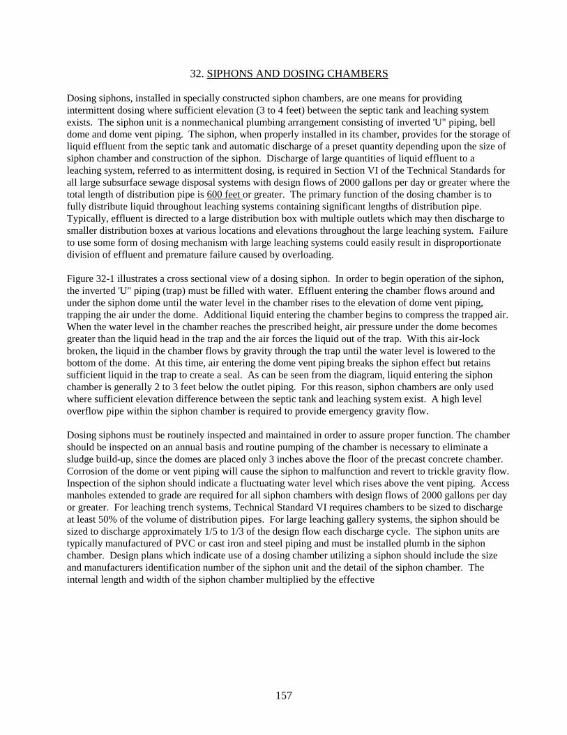
157
32. SIPHONS AND DOSING CHAMBERS
Dosing siphons, installed in specially constructed siphon chambers, are one means for providing
intermittent dosing where sufficient elevation (3 to 4 feet) between the septic tank and leaching system
exists. The siphon unit is a nonmechanical plumbing arrangement consisting of inverted 'U" piping, bell
dome and dome vent piping. The siphon, when properly installed in its chamber, provides for the storage of
liquid effluent from the septic tank and automatic discharge of a preset quantity depending upon the size of
siphon chamber and construction of the siphon. Discharge of large quantities of liquid effluent to a
leaching system, referred to as intermittent dosing, is required in Section VI of the Technical Standards for
all large subsurface sewage disposal systems with design flows of 2000 gallons per day or greater where the
total length of distribution pipe is 600 feet or greater. The primary function of the dosing chamber is to
fully distribute liquid throughout leaching systems containing significant lengths of distribution pipe.
Typically, effluent is directed to a large distribution box with multiple outlets which may then discharge to
smaller distribution boxes at various locations and elevations throughout the large leaching system. Failure
to use some form of dosing mechanism with large leaching systems could easily result in disproportionate
division of effluent and premature failure caused by overloading.
Figure 32-1 illustrates a cross sectional view of a dosing siphon. In order to begin operation of the siphon,
the inverted 'U" piping (trap) must be filled with water. Effluent entering the chamber flows around and
under the siphon dome until the water level in the chamber rises to the elevation of dome vent piping,
trapping the air under the dome. Additional liquid entering the chamber begins to compress the trapped air.
When the water level in the chamber reaches the prescribed height, air pressure under the dome becomes
greater than the liquid head in the trap and the air forces the liquid out of the trap. With this air-lock
broken, the liquid in the chamber flows by gravity through the trap until the water level is lowered to the
bottom of the dome. At this time, air entering the dome vent piping breaks the siphon effect but retains
sufficient liquid in the trap to create a seal. As can be seen from the diagram, liquid entering the siphon
chamber is generally 2 to 3 feet below the outlet piping. For this reason, siphon chambers are only used
where sufficient elevation difference between the septic tank and leaching system exist. A high level
overflow pipe within the siphon chamber is required to provide emergency gravity flow.
Dosing siphons must be routinely inspected and maintained in order to assure proper function. The chamber
should be inspected on an annual basis and routine pumping of the chamber is necessary to eliminate a
sludge build-up, since the domes are placed only 3 inches above the floor of the precast concrete chamber.
Corrosion of the dome or vent piping will cause the siphon to malfunction and revert to trickle gravity flow.
Inspection of the siphon should indicate a fluctuating water level which rises above the vent piping. Access
manholes extended to grade are required for all siphon chambers with design flows of 2000 gallons per day
or greater. For leaching trench systems, Technical Standard VI requires chambers to be sized to discharge
at least 50% of the volume of distribution pipes. For large leaching gallery systems, the siphon should be
sized to discharge approximately 1/5 to 1/3 of the design flow each discharge cycle. The siphon units are
typically manufactured of PVC or cast iron and steel piping and must be installed plumb in the siphon
chamber. Design plans which indicate use of a dosing chamber utilizing a siphon should include the size
and manufacturers identification number of the siphon unit and the detail of the siphon chamber. The
internal length and width of the siphon chamber multiplied by the effective

158
drawdown of the siphon will determine cubic feet of discharge per cycle. Conversion to gallons per cycle
may be achieved by multiplying the cubic feet quantity by 7.5.
3”, 4”, 5”, 6”, 8” Standard Design Single Sewage Siphons
Figure 32-1 - Siphon Chamber
Approximate Dimensions in Inches and Average Weights in Pounds
Diameter of Siphon A 3 3 4 4 5 6 8
Drawing Depth D 13 15 14 17 23 30 35
Diameter of Discharge Head C 4 4 4 4 6 8 10
Diameter of Bell B 10 10 12 12 15 19 24
Invert Below Floor E 4.25 4.25 5.5 5.5 7.5 10 12
Depth of Trap F 13 13 14.25 14.25 23 30.25 36.5
Width of Trap G 10 10 12 12 14 16 22.5
Height Above Floor H 7.25 9.25 8.75 11.75 9.5 11 13.5
Invert to Discharge = D+E+K J 20.25 22.25 22.25 25.5 33.5 44 52
Bottom of BeLl to Floor K 3 3 3 3 3 4 5
Center of Trap to End of Discharge EU L 8.65 8.65 11.75 11.75 15.5 17.5 23.5
Diameter of Carrier S 4 4 4-6 4-6 6-8 8-10 12-15
Average Discharge Rate G.P.M. - 72 76 157 165 328 474 950
Maximum Discharge Rate G.P.M. - 96 104 213 227 422 604 1210
Minimum Discharge Rate G.P.M. - 48 48 102 102 234 340 690
Shipping Weight in Pounds - 60 70 110 120 190 300 500
D
K
2”
H
B
SE C
F
A
G
L
J
BELL
HIGH WATER LEVEL
LOW WATER
LEVEL
HIGH LEVEL
OVERFLOW
4”
TRAP MUST BE CAST IN
PLACE IN FLOOR OF
SIPHON CHAMBER

159
The use of dosing siphons is not restricted to large sewage disposal systems and, on occasions, are included
in designs of residential sewage disposal systems. On lots where slow seeping soil requires installation of
narrow trenches which may exceed over 500 lineal foot in length, a siphon may be helpful in distributing
effluent uniformly. The inlet piping to the siphon chamber must be located a minimum of 3 inches above
the high level overflow.
FLOUTING OUTLET (FLOUT) DOSING CHAMBER
The FLOUT dosing chamber has been approved by the Department of Public Health as a substitute for a
conventional siphon chamber. The FLOUT consists of a waterproof PVC weighted box with one or more
discharge hoses connected to discharge pipes set low in a large concrete distribution box. The flexible hose
connecting the discharge pipes to the PVC box act as a tether which allows the box to pivot at the outlet
pipes. As effluent enters the chamber, the plastic box begins to float and rises to a predetermined height
until the liquid level reaches a large diameter hole at the top of the PVC box. As the box begins to fill with
effluent and subsequently sinks, the total volume accumulated in the chamber quickly discharges to the
leaching system. The flexible hoses connecting the discharge pipes to the water proof box are the only
moving parts.

160
33. SUBSURFACE SAND FILTERS
In the design of small subsurface sewage disposal systems, buried sand filters may be used to produce a
partially stabilized effluent for application to subsurface irrigation systems or evaporation-transpiration
mounds. They also may be used for oxidizing septic tank effluent before it is applied to denitrification
contact beds. In a conventional subsurface sand filter, septic tank effluent is distributed through a system of
perforated pipe and stone over the surface of a buried sand bed. The septic sewage is filtered and oxidized
as it passes through the sand bed. Effluent is collected below the sand bed and is discharged to a
conventional or modified leaching system. In most subsurface sand filters, effluent is applied intermittently
by pumps or siphons to produce a relatively uniform biological growth in the filter and a better stabilized
effluent. Modified subsurface sand filters may be designed for higher filtration rates, sometimes with
provisions for effluent recirculation. Occasionally such filters are used for final filtration of aerated sewage
effluent. High rate subsurface sand filters usually are placed in buried concrete tanks or structures with
access openings to the sand surface which allow cleaning if excessive clogging occurs.
CONVENTIONAL SUBSURFACE SAND FILTERS
Figure 33-1 shows the construction of a conventional subsurface sand filter, as typically designed for use
with small subsurface sewage disposal systems. Septic tank effluent is discharged to the filter intermittently
by means of a siphon or dosing chamber. The chamber usually is sufficiently large so that it does not
discharge more than once or twice daily. The surge produced when the siphon discharges tends to
surcharge the distribution pipe of small subsurface sand filters. For this reason, small filters frequently are
designed with 6 inch diameter distribution pipe which will accommodate a larger liquid volume. Locating
distribution boxes in the center of the filter and connecting the ends of the distribution pipe also are helpful
in preventing siphon discharging. Perforated distribution pipe are laid 4 to 6 feet on centers in a continuous,
10 to 16 inch deep layer of 1/2 to 1 inch broken stone. The top of the stone layer is protected with filter
fabric to prevent dirt and silt from being washed down onto the sand surface.
The filter bed itself consists of 24 to 30 inches of carefully selected sand. The sand must be relatively
coarse and extremely uniform so that it will not become clogged by the buildup of fine inorganic particles
which are the end product of biological decomposition. The sand should have an effective size of between
0.4 and 0.6 millimeters and a uniformity coefficient of 3.5 or less. The effective size is the sieve size which
allows 10% of the grains to pass. The uniformity coefficient is the ratio of the sieve size which passes 60%
of the sand to that which passes 10% of the sand. It is highly unlikely that any bankrun sand will meet this
specification, no matter how good it may appear. Filter sands normally are screened and washed to meet
gradation requirements. Subsurface sand filters receiving septic tank effluent usually are designed for a
loading rate of about 1 gallon of effluent per day for each square foot of bed surface. Such a loading rate
will allow aerobic conditions to be maintained throughout most of the filter, particularly when effluent is
intermittently applied. This promotes the growth of nitrifying organisms and higher forms of protozoan
which are able to reduce the BOD in the filter effluent to less than 5 milligrams per liter, and to oxidize over
80% of the nitrogen to the nitrate form. The suspended solid content of subsurface sand filter effluent
normally is less than 5 milligrams per liter and the dissolved oxygen exceeds 50% of saturation.
Filter effluent is collected in a layer of 1/2 to 1-inch stone underlying the sand bed and is carried away by
perforated collection type. It is important that the top of the stone layer is covered with

161
Figure 33-1 Subsurface Sand Filter
SIPHON OR
PUMP
TO LEACHING
SYSTEM
SAND BED, 20’ x 20’ =
400 SQ. FT.
PERFORATED DIST.
PIPE 5’ ON CENTERS
PERFORATED COLLECTION
PIPE 5’ ON CENTERS
LARGE DISTRIBUTION
BOX FOR SURGE
CHAMBER
12”
24” - 30”
12”
FILTER FABRIC
FILTER FABRIC
SELECT FILTER SAND - EFFECTIVE SIZE 0.4 - 0.6 MM
UNIFORMITY COEFFICIENT 3.5 OR LESS

162
filter fabric to prevent the filter sand from being washed away. Normally, the collection pipe is vented to
ground surface to promote air circulation and help maintain aerobic conditions in the sand bed.
MODIFIED SUBSURFACE SAND FILTERS
Figure 33-2 shows a modified subsurface sand filter as might be used with a small subsurface sewage
disposal system. The entire sand bed is placed within a concrete structure. No system of distribution pipe
is used to apply sewage to the filter. Instead, sewage is applied freely to the uncovered surface of the sand.
Higher loading rates are possible because the sand surface can be cleaned through access openings in the
concrete cover. This structure is vented to the atmosphere and aerobic conditions are maintained either by
recirculating filter effluent or by applying aerated sewage effluent from a small packaged aeration unit.
The gradation and depth of the sand bed is comparable to that of a conventional subsurface sand filter, but
the loading rate usually is considerably higher. Loadings of 2 to 10 gallons per day per square foot of filter
surface may be used. This may produce a clogging mat on the sand surface which must be periodically
removed. High hydraulic loadings may produce saturated flow conditions through the filter and
consequently lowered rates of BOD removal and effluent nitrification. This can be overcome by
recirculating the filter effluent by means of a pump. Recirculation rates are adjusted as required, with a
recirculation ratio of about 4 volumes of recirculated filter effluent for each volume of applied sewage
being about average.
Figure 33-2 High Rate Subsurface Sand Filter
. . . . . . . . . . . . . PEA STONE . . . . .
. .
Hatch Doors or Removable Cover
Inlet
Outlet
Splash
PlateSand Surface
24” - 30” Select Filter Sand
Filter Fabric
1/2” - 1” Stone
Concrete
Tank
8’ X 10’ =
80 sq.ft.
Surface Area
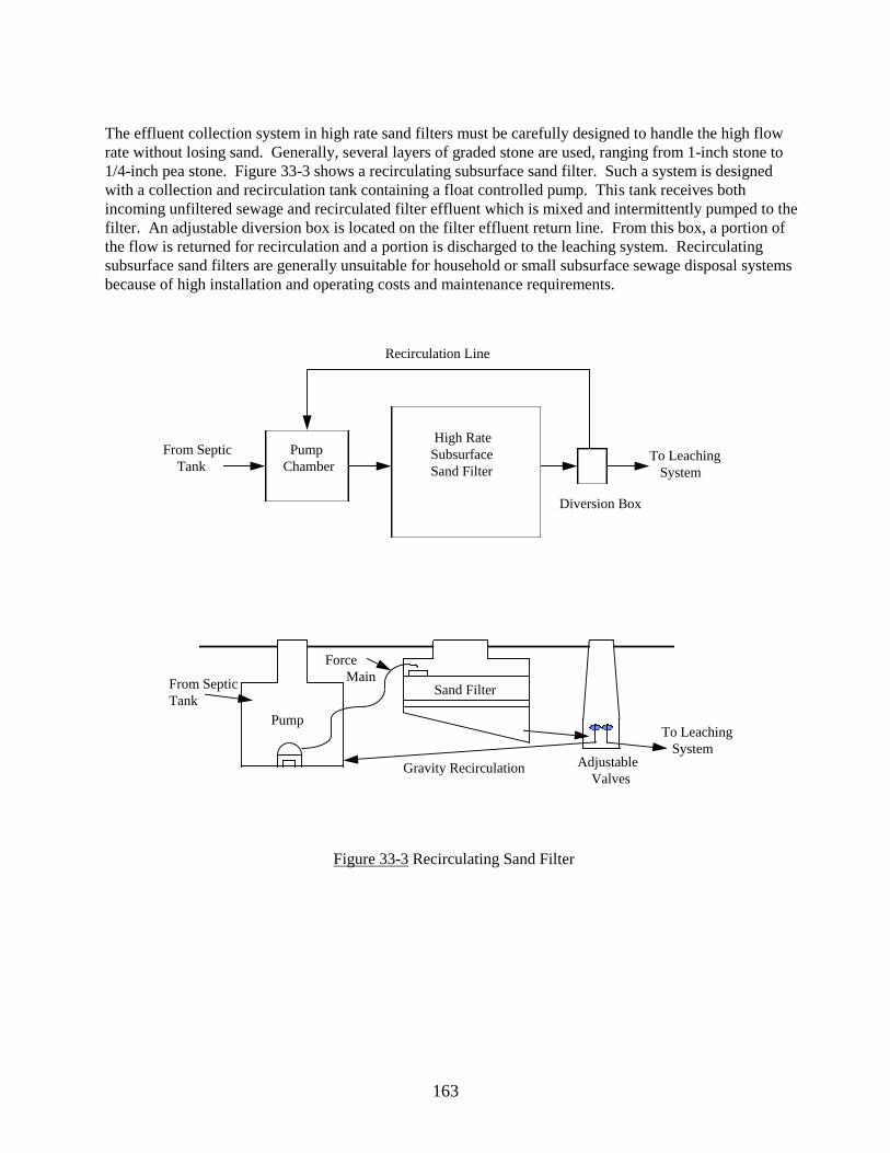
163
The effluent collection system in high rate sand filters must be carefully designed to handle the high flow
rate without losing sand. Generally, several layers of graded stone are used, ranging from 1-inch stone to
1/4-inch pea stone. Figure 33-3 shows a recirculating subsurface sand filter. Such a system is designed
with a collection and recirculation tank containing a float controlled pump. This tank receives both
incoming unfiltered sewage and recirculated filter effluent which is mixed and intermittently pumped to the
filter. An adjustable diversion box is located on the filter effluent return line. From this box, a portion of
the flow is returned for recirculation and a portion is discharged to the leaching system. Recirculating
subsurface sand filters are generally unsuitable for household or small subsurface sewage disposal systems
because of high installation and operating costs and maintenance requirements.
Figure 33-3 Recirculating Sand Filter
From Septic
Tank
Pump
Chamber
Recirculation Line
High Rate
Subsurface
Sand FilterTo Leaching
System
Diversion Box
From Septic
Tank
Pump
Force
Main Sand Filter
Gravity Recirculation Adjustable
Valves
To Leaching
System