23: ' # '8& *#2 & 9 - intechcdn.intechopen.com/pdfs-wm/38164.pdfantennas for...
TRANSCRIPT

3,350+OPEN ACCESS BOOKS
108,000+INTERNATIONAL
AUTHORS AND EDITORS114+ MILLION
DOWNLOADS
BOOKSDELIVERED TO
151 COUNTRIES
AUTHORS AMONG
TOP 1%MOST CITED SCIENTIST
12.2%AUTHORS AND EDITORS
FROM TOP 500 UNIVERSITIES
Selection of our books indexed in theBook Citation Index in Web of Science™
Core Collection (BKCI)
Chapter from the book New Advances in Vehicular Technology and AutomotiveEngineeringDownloaded from: http://www.intechopen.com/books/new-advances-in-vehicular-technology-and-automotive-engineering
PUBLISHED BY
World's largest Science,Technology & Medicine
Open Access book publisher
Interested in publishing with IntechOpen?Contact us at [email protected]

Chapter 7
© 2012 Koch, licensee InTech. This is an open access chapter distributed under the terms of the Creative Commons Attribution License (http://creativecommons.org/licenses/by/3.0), which permits unrestricted use, distribution, and reproduction in any medium, provided the original work is properly cited.
Antennas for Automobiles
Niels Koch
Additional information is available at the end of the chapter
http://dx.doi.org/10.5772/51505
1. Introduction
In recent years, we spent more and more time in our cars. So it became obvious to
implement Car Entertainment Systems into the car for comfort and driver information. Car
entertainment began with AM-reception on short wave bands. FM-tuners on VHF bands
followed soon, with stereo sound, cassette players and CD-players to entertain passengers.
Today we know a number of different analog- and digital broadcasting systems, such as
DAB, DMB, DRM, DVB, as well as satellite broadcasting systems such as SDARS.
For driver information, modern navigation systems not only help to find the most efficient
route, but also give an overview of traffic situation. Car-to-Car Communication and Car-to-
Infrastructure Communication is currently one of the most popular field of researches for
efficient car information systems.
All of these systems have in common that they are wireless systems, hence a number of
antennas must be used satisfying all different services in different frequency bands. In
modern cars we find up to 24 antennas placed on the vehicle and inside the vehicle. In the
next years the number will even rise.
This Chapter is structured into different subsections. At first we set the requirements for
vehicular antennas. Then we search for locations where to place the antenna for optimal
reception and for which service and wireless system the best antenna technology is selected. All
this is fundamentally supported by best-practice examples, including how to beat fading effects.
2. Requirements for vehicular antennas
In order to have a good reception in a vehicle, some prerequisites must be fulfilled.
First of all, and this seems very obvious, the antenna must receive from any direction
around the car. If this requirement cannot be satisfied with one antenna only, then an
antenna array (two or more antennas) shall be considered.

New Advances in Vehicular Technology and Automotive Engineering 192
In general, an antenna shall be as high over ground on the vehicle as possible. The higher
the antenna is placed over ground, the better is can receive and transmit.
Then the antenna must be integrated into the car easily. The distance to the receiver shall be
not too far so that received signals are not extra attenuated before they are used. The
surrounding of the antenna may influence the antenna performance severely. Hence the
materials and distances around the antenna must be considered. As a rule of thumb, a box
of 3 times antenna size around the antenna shall be unobstructed. That means for VHF-
antennas with 75 cm length, this requirement can never be fulfilled on regular cars, but can
be easily achieved with Telephone or GPS-antennas above 1 GHz.
The engine generates spurious noise which can disturb reception, therefore the antenna
shall be placed as far away from the engine as possible, but taking all other requirements
mentioned before into account. So in total there will be a trade-off between height over
ground, omnidirectional reception and reducing spurious emissions influences.
Sometimes the polarization of the antenna is of some importance, as some signals are
transmitted specially polarized, e.g. SDARS is left hand circular polarized.
Summary of requirements for ideal antenna placements
Antennas must be high above ground and receive from all azimuth directions
Antennas must be unobstructed, >3*size
Minimum coupling with other metallic structures or antennas
Distance to receiver (cable-length) short
Distance to spurious emissions as large as possible
Some antenna types require large ground plane, either galvanic connected or coupled
Polarization of the transmitted service and antenna shall be considered
3. Overview on vehicular antenna placements
Watching different cars on the road in terms on antenna placements, it seems that there are a
number of placements to be found.
Figure 1 displays the best practices to place antennas to vehicles.
Figure 1. Suitable antenna placement on a regular passenger car
Trunk
Roof
Rear-Screen Fender
Bumper
Window
Mirror

Antennas for Automobiles 193
3.1. Roof
Most car manufacturers use the roof to place an antenna. This has an obvious reason, because
the roof of a car is the high above ground and unobstructed. This provides a good reception
into every direction. Mostly, omni directional reception is required anyway, so placing the
antenna on the roof is one of the best options for most of the vehicles, except convertibles.
3.2. Spoiler
Some sportive cars exhibit a spoiler for better down force on higher speeds. When the
spoiler is made of plastic, it can be used to place antennas inside. Racing cars use this
technique for telemetry communication.
Regular hatchback cars can have a little spoiler, in which a number of antennas can be
implemented. This method works exceptionally well and is the second preferred place,
whenever a spoiler is present.
3.3. Screens and windows
Placing antenna structures into windscreens, side windows or rear-windows has become
very popular for premium car manufacturers since 1980. As most cars have glass windows,
to which an antenna structure can be applied, it is a cheap but effective method. Here the
antenna structure can be either on the glass or along the frame. The glass itself is usually big
enough to inherit large antenna structures or many different antennas. On-glass antennas
require a larger engineering effort but can be manufactured with low costs once the
structure is developed. Especially when the design of a car is of importance and roof
antennas would not suite aesthetic aspects, then on-glass antennas is the way forward.
3.4. Fender and bumper
Some of the fenders or bumpers are made of plastic, which suite for placing the antennas
behind as they can offer enough free room. However, special care must be taken for easy
repair, as bumper and fenders can crash. Also take into consideration that engine noise and
low height above ground might degrade antenna performance.
3.5. Trunk cover
Alternatively to the roof, the trunk cover is a suitable position to contain a number of
antennas. Especially for convertible vehicles, where the roof and screens can be hidden, the
trunk cover is advised to place antennas into. However, the trunk cover must be made of
plastic or a double-layer structure with metal frame and plastic cover on top.
3.6. Mirrors
Light trucks and sport utility vehicles (SUV) offer huge side mirrors in comparison to
normal cars. The shell of the mirror is mostly plastic. Inside these mirrors a number of

New Advances in Vehicular Technology and Automotive Engineering 194
higher frequency antennas can be placed. Some truck side mirrors are large enough to
inherit a combination of FM-receiving antenna at VHF-band, Telephoning antenna from
GSM and CDMA systems, a GPS navigation antenna and on top a SDARS satellite
broadcasting antenna. Regular vehicle side mirrors can offer some space for higher
frequency services above 1 GHz, e.g. Car-2-Car communication at 5,9 GHz.
3.7. Summary of ideal antenna placements
There are many positions possible to place antennas on a vehicle, but not all are good for
each type of car. For good reception of wireless systems, there are a number of factors to be
considered.
As stated in the chapter 2 on general requirements, the antenna must be as high as possible
above ground for long path transmission. The antenna must be unobstructed to
communicate into all directions well.
Combining both prerequisites translates into the rule of thumb, that antennas shall be
operate as freely as possible, which means, the more an antenna packed into a structure, the
less efficient it is.
Some antenna structures are easier to handle even in tight environment and some antenna
technologies are very fragile in terms of antenna characteristics in tight metallic
surroundings. Selecting the appropriate antenna structures helps finding a compromise
between antenna position and performance.
4. Overview on possible antenna technologies
Antennas can be placed on the vehicle on many places, but only a few positions are ideal. To
define which position is ideal, this must be considered for the service and frequency band as
well as in conjunction with selected antenna technology. Here we give a short overview
about the most popular antenna technologies
4.1. Monopoles
Monopole antennas are the most popular antenna type, as they are very easy to handle, easy
to manufacture, easy to implement to the vehicle and very cheap.
A monopole antenna consists of an antenna foot and the rod of some length. Placing the
antenna on the roof of a car requires just a hole in the metallic structure for the antenna foot
and the cable to be attached.
The rod can be a stiff metallic stick of a quarter wavelength (0,25*λ) or longer. There are
rods which are telescopic or even flexible. Monopoles provide a broad range of applications
in every frequency band, from VHF sound broadcasting up to car-2-car communication at
5.9 GHz. The monopole can be placed in the roof center, on an edge of the roof or on the
frame, or even on a bumper or fender. This antenna technology is quickly implemented to

Antennas for Automobiles 195
nearly anywhere on the vehicle. In conjunction with a very competitive pricing due to quick
development and easy manufacturing, monopoles are the first choice in the automotive
industry.
The monopole antenna requires a direct connection to ground, meaning the metallic
structure of the vehicle. The monopole will not work efficiently when the metallic ground is
small in comparison to the wavelength λ. Minimum 0,25*λ is required for ground plane to
neglect effects.
However, aesthetically speaking, the rod antenna on a roof or fender does not satisfy
modern design emotions, so car designers try to avoid simple rod antennas on their cars.
Especially for premium car manufacturers, rod antennas are meant to be avoided in modern
car antenna system concepts.
4.2. Patch antenna
In principal, a patch antenna is a flatted monopole. Figure 2 shows the principal structure of
a patch antenna. A metallic plate of about half wavelength (0,5*λ) is placed over a metallic
ground plane, which are separated either by air or a low loss dielectric material. The RF is
ideally fed directly to the radiating patch.
This antenna type is becoming more and more popular in the automotive industry. At first
just for high frequency applications beyond 1 GHz, such as for GPS reception at 1,5 GHz or
SDARS satellite broadcasting radio reception at 2,3 GHz, WLAN and Car2Car
Communication at 5-6 GHz, but nowadays increasingly seen for telephoning antennas for
GSM and CDMA at 800/900 MHz.
As this antenna type is unobtrusively flat and can be implemented into the vehicles
structure, e.g. behind a fender or bumper or in a plastic trunk cover. Patch Antennas require
a large metallic ground structure, preferably flat of minimum 1*λ around the antenna. If the
vehicle cannot fulfil this requirement at the position with its surrounding metallic structure,
then the patch antenna shall provide its own ground plane in the antenna structure.
Figure 2. Principal structure of a squared patch antenna
Feed Point
Dielectric
Ground Plane >1*λ
Ground Plane >1*λ
0,5*λ
0,5*λ
Dielectric

New Advances in Vehicular Technology and Automotive Engineering 196
4.3. On-glass antenna
This antenna type became popular in the premium car industry in the 1980, when design
topics became increasingly important. With on-glass antennas it becomes possible to hide a
number of antennas for the regular user’s eye. As most vehicles have glass windows, an
antenna structure can be implemented there.
The most straight forward antenna technique for on-glass follows a slot antenna principle.
Here the metallic car structure becomes part of the antenna and the glass (windscreen, side
window or rear window for example) is used as the slot in the metallic structure. Coupling
this slot with a thin conductor, the slot resonates and can be used as antenna. The feeding
position is of some importance. With a clever selection of the feeding position, different
modes can be activated, which can help to excite certain polarities or radiation behaviour.
Figure 3 shows the slot antenna principle which explains on-glass antenna function.
As defrosting conductor elements are already placed to the rear window, these conductors
can be applied for such on-glass antenna structures. Here, a simple filter is used to separate
the DC-current for defrosting from the radio frequency (RF).
The development of such on-glass antennas can take some time, as car structure and glass
window holes in the metallic structure are both parts of the antenna jointly, which influence
each other. So changing the shape of the car will change the on-glass antenna characteristics.
But once a suitable structure is found, the manufacturing process is very cheap.
Figure 3. Slot antenna principle for on-glass antennas. Different feed point options are indicated which
excite different modes for special radiation characteristics
4.4. Glued foil antenna
Similar to slot antennas and patch antennas, these structures can be placed on metallic foil,
which is glued to a plastic element.
So very flat antenna structures can be produced, which can be placed into rear-view-
mirrors, side-mirrors, spoilers, bumper and fenders or any non-metallic parts of the vehicle.

Antennas for Automobiles 197
However there are some disadvantages to be mentioned, which are the very narrow usable
bandwidth and the problem to connect coaxial cables to the flat foil antenna. In addition,
moisture and spray water shall be avoided.
The connection problem is often solved by coupling the signal to the structure, but losses
must be taken into account. The structure shape is virtually unlimited so that a huge variety
can be found in books and journals.
Figure 4 shows one example of foil antenna structure.
4.5. Fractal antenna
A very modern field of antenna technology is summarized as fractal antennas. It has been
found that not only some structures repeat their resonance with n*λ, but also when
repeating the structure in itself. This fractal breakdown of a wire structure or a patch
antenna structure leads to multiple resonances of the antenna. When tuning the structure
that many frequency ranges can be used, only one antenna could be used to serve most of
the required services.
As the benefit is that only a few antennas need to be placed, which is good for small cars, the
disadvantage is the very limited usable bandwidth where the structure resonates.
Figure 5 shows an example of a fractal antenna principle.
Figure 4. Thin foil antenna structures on a roll
Figure 5. Sierpinski fractal antenna structure

New Advances in Vehicular Technology and Automotive Engineering 198
5. Selecting antennas according to services
Broadcasting systems reign a long history so backward compability is a major requirement
also for modern cars. Although the number of mobile shortwave listeners is very limited,
each car entertainment system offers shortwave-reception.
Table 1 summarizes the existing broadcasting systems.
5.1. Short- and medium wave bands
Short wave (SW) and medium wave (MW) band provide a worldwide coverage due to
ground wave propagation and wave reflection at ionosphere layers in the atmosphere. As
these layers are approximately 80 km to 300 km high, a large distance can be bridged. For
large-area countries such as Australia, Brazil or Canada just to name a few, a nation-wide
broadcasting coverage can easily be done on MW-bands. From history we adopted AM-
modulated signals with relatively poor sound quality, compared to today’s quality
expectations. Vehicular SW-antennas are difficult to implement, as the car is always too
small even for quarter wavelength antennas. So an electrically shorted monopole must be
used then, which is applied as rod antenna. In some occasions the rear window or a plastic
spoiler can be used.
5.2. Digital Radio Mondiale (DRM)
In order to overcome poor sound problems in SW/MW-bands, transmission became digital.
Digital Radio Mondiale (DRM) decodes sound information to a digital data stream which is
modulated with OFDM and broadcasted on SW/MW-bands. The receiver can decode this
data stream and correct transmission errors. The sound quality is intuitively better than
analog broadcasting but coverage is found to be reduced. That is mainly due to the fact that
digital wireless systems have an abrupt go-nogo border, while analog systems degrade
gradually until signals disappear in noise [1].
5.3. VHF-band and UHF-band
Around 1950, VHF-frequency spectrum was utilized in Europe. Radio propagation in 100-
MHz-band can reach approximately 30% beyond the optical horizon, so called radio
horizon. This leads to a limited coverage of sound or TV broadcasting stations. Depending
on transmitter location and radiated transmit power the typical coverage area is about 100
km². For a nation wide broadcasting network, a high number of transmitters must be
installed. Especially in hilly terrain uncovered areas occur due to radio shadows. When
reception is needed there, filling transmitters are needed. On VHF-band (76-109 MHz)
sound broadcasting is transmitted while on UHF-band (400-800 MHz) TV-broadcasting is
located. Typically, a dual layer broadcasting network is rolled out in VHF- and UHF-bands.
The first layer consists of transmitters with high power on prominent locations, covering a
large area. The second layer fills coverage gaps with low-power transmitters.

Antennas for Automobiles 199
As each transmitter requires a separate frequency in order not to interfere with each other,
the dedicated frequency spectrum is quickly used up. Clever frequency allocation and
frequency reuse is needed.
For VHF and UHF a number of antenna techniques can be used. The cheapest version is
using a monopole, but on-glass slot antenna structures offer a very efficient way as well. If
the vehicle has a plastic spoiler or a plastic fender/bumber, it can inherit VHF/UHF
antennas.
5.4. Digital broadcasting systems
In 1987 development of digital broadcasting systems began and a number of digital
transmission standards derived since then. Digital Audio Broadcasting (DAB), former
Eureka-147 Project, was the start into digital data processing and digital broadcasting
transmission. DAB decodes sound information to a digital data stream which is modulated
with 4-PSK-OFDM and broadcasted on VHF-band. The receiver can decode this data stream
and correct transmission errors. The sound quality is intuitively better than analog
broadcasting. Similar to all other digital wireless systems, DAB reception is experienced
having an abrupt go-nogo border, which is often misunderstood that coverage is smaller
than analog systems [1].
One of the benefits of digital broadcasting system is that more programs can be transmitted
with one frequency allocation. While in analog broadcasting one radio station used one
frequency, now up to 64 radio stations can be received on one single frequency. This offered
new broadcasting capacity for more divert channels covering more genres and clientele.
Another benefit of digital transmission is the higher sound quality.
With better coding capabilities using MP3 and MP4 codecs a more efficient transmission
could be implemented. Digital Multimedia Broadcasting (DMB) is using MP4 AAC+ codec
in contrast to DAB, where MUSICAM codec is implemented. For video transmission, Digital
Video Broadcasting (DVB) is used. DVB is similar to DAB and DMB, except that video
signal compression H.264 is added to sound compression algorithms and higher intrinsic
modulation schemes are used, often 16QAM-OFDM. DVB is successively replacing analog
TV-transmitters in Europe.
The placement for DAB antennas shall be properly selected, keeping the spurious emission
noise in mind.
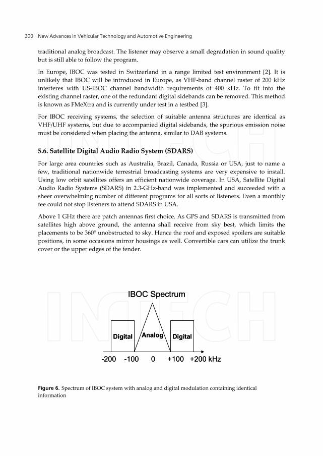
5.5. IBOC system
In USA, another method of digitalization is used. Beside the analog modulated signal, an
additional digital modulated signal with same content is transmitted, so called in-band on
channel (IBOC) signal. Figure 6 displays the spectrum of such an IBOC signal.
Having good reception, the tuner decodes the digital information and provides high-quality
sound. Reaching the go-nogo-border of digital transmission, the tuner switches to
New Advances in Vehicular Technology and Automotive Engineering 200
traditional analog broadcast. The listener may observe a small degradation in sound quality
but is still able to follow the program.
In Europe, IBOC was tested in Switzerland in a range limited test environment [2]. It is
unlikely that IBOC will be introduced in Europe, as VHF-band channel raster of 200 kHz
interferes with US-IBOC channel bandwidth requirements of 400 kHz. To fit into the
existing channel raster, one of the redundant digital sidebands can be removed. This method
is known as FMeXtra and is currently under test in a testbed [3].
For IBOC receiving systems, the selection of suitable antenna structures are identical as
VHF/UHF systems, but due to accompanied digital sidebands, the spurious emission noise
must be considered when placing the antenna, similar to DAB systems.
5.6. Satellite Digital Audio Radio System (SDARS)
For large area countries such as Australia, Brazil, Canada, Russia or USA, just to name a
few, traditional nationwide terrestrial broadcasting systems are very expensive to install.
Using low orbit satellites offers an efficient nationwide coverage. In USA, Satellite Digital
Audio Radio Systems (SDARS) in 2.3-GHz-band was implemented and succeeded with a
sheer overwhelming number of different programs for all sorts of listeners. Even a monthly
fee could not stop listeners to attend SDARS in USA.
Above 1 GHz there are patch antennas first choice. As GPS and SDARS is transmitted from
satellites high above ground, the antenna shall receive from sky best, which limits the
placements to be 360° unobstructed to sky. Hence the roof and exposed spoilers are suitable
positions, in some occasions mirror housings as well. Convertible cars can utilize the trunk
cover or the upper edges of the fender.
Figure 6. Spectrum of IBOC system with analog and digital modulation containing identical
information
AnalogDigital Digital
-200 -100 0 +100 +200 kHz
IBOC Spectrum
AnalogDigital Digital
-200 -100 0 +100 +200 kHz
IBOC Spectrum

Antennas for Automobiles 201
System Name Abbreviation Frequency Band ModulationLong-Short-Medium Wave LW/MW/SW 172 kHz - 30 MHz Amplitude Modulation AM
Ultra short Wave VHF 76 MHz - 109 MHz Frequency Modulation FM
In-Band On-Channel IBOC 76 MHz - 109 MHzQuadratur Phase Shift Keying,
QPSK
Digital Broadcasting System DAB 174 MHz - 210 MHzOrthogonal Frequency Division
Multiplex, OFDMDigital Broadcasting System with
enhanced codecDAB+ 174 MHz - 210 MHz
Orthogonal Frequency Division Multiplex, OFDM
Digital Multimedia Broadcasting DMB 174 MHz - 210 MHzOrthogonal Frequency Division
Multiplex, OFDM
terrestrial Digital Video Broadcasting DVB-T 480 MHz - 860 MHzOrthogonal Frequency Division
Multiplex, OFDMterrestrial Digital Video Broadcasting
with enhanced codecDVB-T2 480 MHz - 860 MHz
Orthogonal Frequency Division Multiplex, OFDM
Satellite Digital Audio Radio System SDARS 2,30 GHz - 2,33 GHzOrthogonal Frequency Division
Multiplex, OFDM
Table 1. Overview of broadcasting systems
5.7. Best practices - Where to place antennas for services
When looking at various vehicles on the market, there will be seen a number of antenna
solutions on the vehicle structure. The most popular antenna placement is a monopole rod
antenna on the roof of the car, as this method fulfils the most important basic requirements,
high above ground and unobstructed.
The radiation characteristic is quasi omni directional, when the metallic roof is large enough.
For frequencies >100 MHz, which refers to FM-broadcasting reception, TV-reception and
mobile telephoning systems, monopole antennas on vehicle roof are perfectly suited.
In addition, they are very easy to implement and with about 5 EUR or less per piece very
cheap. These are the reason why the majority of the vehicle manufacturers apply monopole
rod antennas.
Sometimes the car designer does not like antennas on the structure. Then hidden antenna
concepts must be used. A very common way is to place the antennas into a plastic spoiler.
As the spoiler is usually high above ground and unobstructed for good airflow, it fulfils
basic requirements for good reception. Racing cars use the spoiler structure for telemetry
communications. Sometimes regular hatchback cars contain a spoiler, into which VHF-
antennas for sound and TV broadcasting, GPS-antennas and nowadays Car-2-Car
Communication antennas can be easily integrated. Of cause it is also possible to apply
telephoning and satellite broadcasting SDARS antennas into spoiler structures.
When there is no sportive spoiler but the design aspects require invisible antennas, the
antennas can be placed into the screens. Here the slot antenna concept is used, which
requires some development but once the structure is found, it is easy and cheap to
manufacture. Usually the rearwindow is used when the engine is in front, offering the

New Advances in Vehicular Technology and Automotive Engineering 202
maximum distance from spurious emission noise. In rare occasions where the engine is in
the backside of the car, e.g. Porsche 911 model, then the windscreen is used. However, the
antenna structure shall not effect visibility then.
Alternatively sidewindows can be used for antenna structures but often they are too small
for multiple antennas and VHF-antennas.
As foil- and fractal antennas became popular for mobile phone antennas, this concept has
also been applied to the car industry. Today we find fractal foil glued antenna structures in
rearview mirrors, e.g. garage door opener, car entry systems and Bluetooth- / WLAN
antennas, just to name a few.
Light trucks and SUVs comprise some large side mirrors, in which even low frequency
antennas can be placed, such as for FM-reception on VHF bands and mobile telephoning
systems.
The only disadvantage is that in a case of an accident with damaging the side mirror, the
wireless service can be damaged as well or reception becomes poor.
In order to avoid a complete loss of service, either both side mirrors can be equipped or a
combination with other antenna locations can be used.
The side effect of this method is that multiple antennas can provide better reception. This
method is known as diversity reception.
6. Diversity - Combating fading
In vehicular receiving environments fading of signals occur due to multipath reception.
When a radio signal is transmitted, it reaches the receiver on a direct path as well as on
reflected paths from buildings, landscape and obstructions, see Figure 7. The reflected paths
reach the receiver at different times than the direct path. This leads to superposition of
multiple signals of the same content. Signals can add or subtract each other at the receiving
zone, leading to a varying loudness impression in amplitude modulated signals and signal
dropouts in frequency modulated signal. In digital systems, bit errors can occur.
A number of methods were invented to reduce the audible effect of multipath fading.
One method is to apply a number of receiving antennas on different positions of the car.
Different antennas at different locations are assumed to receive different signal components.
This effect is known as spatial diversity. A switch selects the best receiving antenna
according to the signal strength and noise level. Figure 8 shows the principle of switching
spatial diversity for VHF-FM reception. Another method is to use both tuners in a dual-
tuner concept which are connected to individual antennas. Due to the different location of
the antennas phase differences occur which are corrected by phase shifters. Then, both
phase corrected receiving signals can be added in-phase and can prevent fading dropouts.
This method is known as phase diversity.

Antennas for Automobiles 203
Figure 7. Principle of multipath environment where transmitter signal is reflected, diffracted and
attenuated by environment. At the receiving zone signal paths are summed.
Figure 8. Principle of switched diversity in modern tuners [1]
In digital broadcasting systems, bit streams can be combined to correct transmission errors.
Here, two receivers operate individually but synchronized by internal clocks. The digital
data streams are compared with each other and bit errors corrected when necessary. The
combined data stream provides a more consistent data rate which results in a better quality
of service for the listener. Figure 9 shows principle bit stream diversity for DAB.
6.1. Best practices - Where to place diversity antennas
When placing diversity antennas, there must be some requirements to be fulfilled.
The main requirement is that antennas used for diversity reception must be mutually
decoupled, meaning that one antenna shall not receive the identical signal than the other,
Receiving zone
)2( idvji eA
Multipath Reception
Receiving zone
)2( idvji eA
Multipath Reception
1 2 3 4
d/dtDiff
FM-receiving antennas
RF to Radio
IF fromRadio
Switch
AmplifierNoisedetectionLogic
1 2 3 4
d/dtDiff
FM-receiving antennas
RF to Radio
IF fromRadio
Switch
AmplifierNoisedetectionLogic

New Advances in Vehicular Technology and Automotive Engineering 204
better to receive a different phase or a different component of the signal. Only then the
fragments can be assembled to a better signal. To achieve this, different antennas shall be
placed at least 3 wavelength apart, so that signal can be received at the different time and
different phase. This method is known as “spatial diversity”. If there is not enough space
for a large gap between antennas, an alternative is to receive different phase components,
which is known as “phase diversity”. In a premium vehicle, diversity reception for FM or
TV is achieved with a combination of phase and spatial diversity. For instance, placing 2
antennas in the rear-window, one is vertically dominated polarized, the other horizontally
dominated polarized. Both rear-window antennas provide good reception, as nearly all
phase components of the multipath signal can be received.
However, having both antennas in the rear of the vehicle, the reception to the front side can
be shadowed. This can be overcome with a third antenna, either a monopole on rooftop or a
structure in the spoiler (if the vehicle has one) or using a structure in the front fender. For
higher frequency ranges, the mirrors can be used, e.g. fractal foil structure glued to the
plastic housing.
Combining rear-window and side-mirror antennas, a fully decoupled but omni directional
reception is achieved where most of the multipath signal components can be processed.
Figure 9. Principle of bit stream combining method for digital broadcasting systems [1]
7. Outlook and future trends
From the performance point of view, a lot can be optimized in the entertainment system in
the future. Especially broadcasting reception is deemed to be improved. Historically, the
tuner was installed in the center console, while the receiving antenna was on the fender. The
cable length was comparably short. A disadvantage of this solution is that engine spurious
emission noise is easily picked up by the antenna and disturbs reception.
1 2DAB-receiving antennas
ReceiverDemod X
Amplifier
ReceiverDemod
Comperator
CombinedData Stream
1 2DAB-receiving antennas
ReceiverDemod X
Amplifier
ReceiverDemod
Comperator
CombinedData Stream

Antennas for Automobiles 205
Modern cars however offer a number of receiving antennas for diversity reception in the
rear-window, side-window, bumper and fender for instance, but long cabling ways
attenuate RF signals.
The wide range of broadcasting standards requires multiple tuners buried in the car.
Integration and size reduction is a major playground in R&D departments. Transceivers of
modern mobile phones are approximately 30x30 mm² or less and 3 mm thick, offering multi-
frequency and multi-standard operation already. With SDR-tuners it will become possible in
near future to provide compact multi-standard broadcasting receivers exploiting diversity
gain by MIMO concepts. This allows integrating such receivers into - or at least close to - the
antennas. Reception performance will improve drastically unless EMC problems occur.
Another mega trend of this decade is a permanent internet connection. With UMTS and
WLAN it is already possible to connect laptops and mobile phones to the internet while
riding in car. In near future, the vehicle itself gets connected to the internet. The mobile
phone standard Long-Term-Evolution (LTE) will support this trend. The merge of internet
services and vehicular entertainment functionality will provide efficiency and convenience
to the passengers. The sheer endless list of new service ideas for the drivers and passengers
is overwhelming and becoming unique selling points for car manufactures. They will offer
new services to drivers, from intelligent traffic routing, parking aid to firmware updates
inside the car. Passengers will be able to stream music and videos as well as communicate
while surfing the internet.
In conjunction with passenger entertainment, Car-2-Car Communication systems offer new
information sources for the driver to plan a trip and offers new safety features during the
ride.
One of many applications is that traffic flow is constantly monitored by ego-speed history
and current data recognition, which will be broadcasted to other vehicles on the road
nearby. Comparing own speed information and vehicles in front of own position allows a
rolling “look-ahead” traffic situation estimation of the upcoming path. This will help to
adjust driving speed to enable a better traffic flow as well as avoid traffic jams.
Another safety aspect of C2C information exchange is on crossroads. Here a central station
receives signals from vehicles approaching and can guide them through the cross-traffic.
With this, right-of-way accidents can be reduced as well as traffic flow improved.
Author details
Niels Koch
Altran GmbH & Co.KG, Germany
8. References
[1] Koch, N. (2008). Diversity for DAB – Worth the Effort ?, 9th Workshop Digital Broadcasting, Fraunhofer Institute IIS Erlangen, Germany

New Advances in Vehicular Technology and Automotive Engineering 206
[2] Henk, C.M, Hamelink, S.G (2008). FMeXtra – the Principle and its Application, 9th Workshop Digital Broadcasting, Fraunhofer Institute IIS Erlangen, Germany
[3] Ruoss, M. (2008). The Digitalization of the FM-Band in Europe, 9th Workshop Digital Broadcasting, Fraunhofer Institute IIS Erlangen, Germany