23 75 00 custom made air handling units
TRANSCRIPT
Capital Projects Group
Custom Made Air Handling Units Specification Specification 23 75 00 Revision 1 Date: September 2018
Custom Made Air Handling Units Specification
Specification 23 75 00
Publication Date: September, 2018 COPYRIGHT © 2018
Metrolinx,
an Agency of the Government of Ontario
The contents of this publication may be used solely as required for and during a project assignment from Metrolinx or for and during preparing a response to a Metrolinx procurement request. Otherwise, this publication or any part thereof shall not be reproduced, re-distributed, stored in an electronic database or transmitted in any form by any means, electronic, photocopying or otherwise, without written permission of the copyright holder. In no event shall this publication or any part thereof be sold or used for commercial purposes.
The information contained herein or otherwise provided or made available ancillary hereto is provided “as is” without warranty or guarantee of any kind as to accuracy, completeness, fitness for use, purpose, non- infringement of third party rights or any other warranty, express or implied. Metrolinx is not responsible and has no liability for any damages, losses, expenses or claims arising or purporting to arise from use of or reliance on the information contained herein.

Amendment Record Sheet
Amendment in Clause No.
Date of Amendment
Description of Changes
Various Sept. 20, 2018 Revised to coordinate with corresponding specifications.
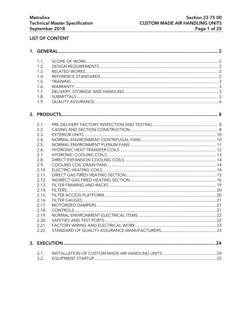
Metrolinx Section 23 75 00 Technical Master Specification CUSTOM MADE AIR HANDLING UNITS September 2018 Page 1 of 25
LIST OF CONTENT
1. GENERAL .......................................................................................................................................... 2
1.1. SCOPE OF WORK ............................................................................................................................. 2 1.2. DESIGN REQUIREMENTS ................................................................................................................ 2 1.3. RELATED WORKS ............................................................................................................................. 2 1.4. REFERENCE STANDARDS ............................................................................................................... 2 1.5. TRAINING .......................................................................................................................................... 3 1.6. WARRANTY ....................................................................................................................................... 3 1.7. DELIVERY, STORAGE AND HANDLING ........................................................................................ 3 1.8. SUBMITTALS ...................................................................................................................................... 3 1.9. QUALITY ASSURANCE ..................................................................................................................... 6
2. PRODUCTS....................................................................................................................................... 8
2.1. PRE-DELIVERY FACTORY INSPECTION AND TESTING .............................................................. 8 2.2. CASING AND SECTION CONSTRUCTION ................................................................................... 8 2.3. EXTERIOR UNITS ............................................................................................................................ 10 2.4. NORMAL ENVIRONMENT CENTRIFUGAL FANS ....................................................................... 10 2.5. NORMAL ENVIRONMENT PLENUM FANS ................................................................................. 11 2.6. HYDRONIC HEAT TRANSFER COILS ........................................................................................... 12 2.7. HYDRONIC COOLING COILS ....................................................................................................... 13 2.8. DIRECT EXPANSION COOLING COILS ...................................................................................... 14 2.9. COOLING COIL DRAIN PANS ...................................................................................................... 14 2.10. ELECTRIC HEATING COILS ........................................................................................................... 14 2.11. DIRECT GAS FIRED HEATING SECTION ..................................................................................... 15 2.12. INDIRECT GAS FIRED HEATING SECTION ................................................................................. 16 2.13. FILTER FRAMING AND RACKS ..................................................................................................... 19 2.14. FILTERS............................................................................................................................................. 20 2.15. FILTER ACCESS PLATFORM ......................................................................................................... 20 2.16. FILTER GAUGES .............................................................................................................................. 21 2.17. MOTORIZED DAMPERS ................................................................................................................. 21 2.18. CONTROLS ...................................................................................................................................... 21 2.19. NORMAL ENVIRONMENT ELECTRICAL ITEMS ......................................................................... 22 2.20. SAFETIES AND TEST PORTS ......................................................................................................... 22 2.21. FACTORY WIRING AND ELECTRICAL WORK ............................................................................ 23 2.22. STANDARD OF QUALITY ASSURANCE MANUFACTURERS .................................................... 23
3. EXECUTION ................................................................................................................................... 24
3.1. INSTALLATION OF CUSTOM MADE AIR HANDLING UNITS ................................................... 24 3.2. EQUIPMENT STARTUP ................................................................................................................... 25
Metrolinx Section 23 75 00 Technical Master Specification CUSTOM MADE AIR HANDLING UNITS September 2018 Page 2 of 25
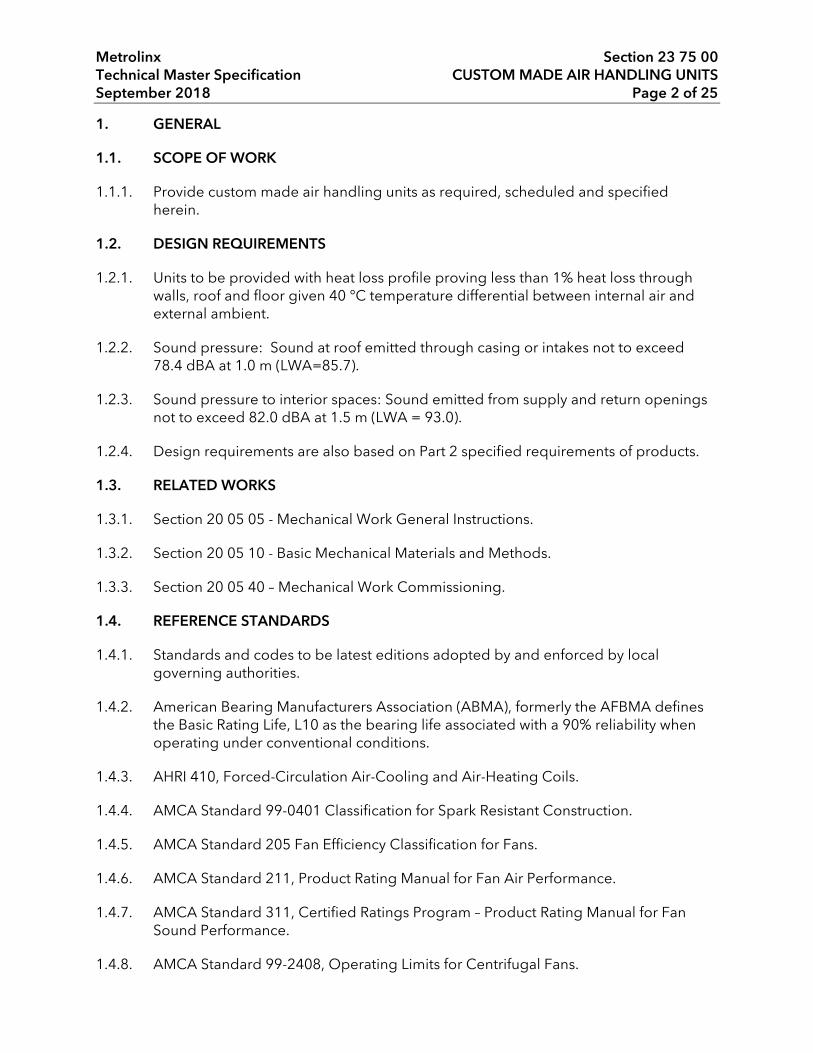
1. GENERAL
1.1. SCOPE OF WORK
1.1.1. Provide custom made air handling units as required, scheduled and specified herein.
1.2. DESIGN REQUIREMENTS
1.2.1. Units to be provided with heat loss profile proving less than 1% heat loss through walls, roof and floor given 40 °C temperature differential between internal air and external ambient.
1.2.2. Sound pressure: Sound at roof emitted through casing or intakes not to exceed 78.4 dBA at 1.0 m (LWA=85.7).
1.2.3. Sound pressure to interior spaces: Sound emitted from supply and return openings not to exceed 82.0 dBA at 1.5 m (LWA = 93.0).
1.2.4. Design requirements are also based on Part 2 specified requirements of products.
1.3. RELATED WORKS
1.3.1. Section 20 05 05 - Mechanical Work General Instructions.
1.3.2. Section 20 05 10 - Basic Mechanical Materials and Methods.
1.3.3. Section 20 05 40 – Mechanical Work Commissioning.
1.4. REFERENCE STANDARDS
1.4.1. Standards and codes to be latest editions adopted by and enforced by local governing authorities.
1.4.2. American Bearing Manufacturers Association (ABMA), formerly the AFBMA defines the Basic Rating Life, L10 as the bearing life associated with a 90% reliability when operating under conventional conditions.
1.4.3. AHRI 410, Forced-Circulation Air-Cooling and Air-Heating Coils.
1.4.4. AMCA Standard 99-0401 Classification for Spark Resistant Construction.
1.4.5. AMCA Standard 205 Fan Efficiency Classification for Fans.
1.4.6. AMCA Standard 211, Product Rating Manual for Fan Air Performance.
1.4.7. AMCA Standard 311, Certified Ratings Program – Product Rating Manual for Fan Sound Performance.
1.4.8. AMCA Standard 99-2408, Operating Limits for Centrifugal Fans.
Metrolinx Section 23 75 00 Technical Master Specification CUSTOM MADE AIR HANDLING UNITS September 2018 Page 3 of 25
1.4.9. ANSI/ASHRAE/IES 90.1, Energy Standard for Buildings Except Low Rise Residential Buildings.
1.4.10. ANSI/AHRI 430, Performance Rating of Central Station Air-Handling Units.
1.4.11. ASHRAE 52.2 Method of Testing General Ventilation Air-Cleaning Devices for Removal Efficiency by Particle Size (ANSI Approved).
1.4.12. ASTM A53 Standard Specification for Pipe, Steel, Black and Hot-Dipped, Zinc-Coated, Welded and Seamless.
1.4.13. CAN/CSA Standard B149.1, Natural Gas and Propane Installation Code.
1.4.14. CSA Standard C22.2 No. 14 Industrial Control Equipment.
1.4.15. CAN/CSA C22.2 No. 236/UL 1995, Heating and Cooling Units.
1.4.16. CAN/ULC S102, Standard Method of Test for Surface Burning Characteristics of Building Materials and Assemblies.
1.4.17. CSA or ETL certification and labelling for all electrical components.
1.4.18. NFPA 54/ANSI Z223.1National Fuel Gas Code.
1.4.19. SMACNA HVAC Duct Construction Standards Metal and Flexible.
1.5. TRAINING
1.5.1. Training is to be a full review of all components including but not limited to a full operation and maintenance demonstration, with abnormal events.
1.5.2. Include for 3 training sessions of maximum 7 hours duration per session for 10 Metrolinx people per session.
1.5.3. Refer to Section 20 05 05 for additional general requirements.
1.6. WARRANTY
1.6.1. Products to be guaranteed by manufacturer, for a minimum of 2 years after acceptance by Metrolinx.
1.7. DELIVERY, STORAGE AND HANDLING
1.7.1. Handle and store products in accordance with manufacturer's instructions, in locations approved by Metrolinx. Include one copy of these instructions with product at time of shipment.
1.8. SUBMITTALS
1.8.1. Refer to submittal requirements in Section 20 05 05.

Metrolinx Section 23 75 00 Technical Master Specification CUSTOM MADE AIR HANDLING UNITS September 2018 Page 4 of 25
1.8.2. Submit manufacturer’s colour chart to indicate standard colour range of paint finishes. Supply 4 L (3.5 qt) of touch-up paint with each custom made air handling unit.
1.8.3. Supply reviewed copies of exterior roof mounting air handling unit/curb assembly shop drawings or product data sheets to trade who will cut roof openings for ductwork, and ensure openings are properly sized and located.
1.8.4. Submit with delivery of each unit a copy of factory test and inspection report as specified in Part 2 of this Section, and include a copy of each report with O & M Manual project close-out data.
1.8.5. Submit a site inspection and start-up report from manufacturer’s representative as specified in Part 3 of this Section.
1.8.6. Submit shop drawings/product data sheets as follows:
a) to regulatory authority for review and approval prior to submitting to Consultant;
b) for all products specified in Part 2 of this Section;
c) copies of all calculations, stamped and signed by same engineer who signs layout drawings, and a listing of all design data used in preparing the calculations, system layout and sizing requirements.
1.8.7. Provide relevant information related to gas heat exchanger, including but not limited to:
a) input rate and output rate;
b) minimum gas pressure required;
c) air temperature rise;
d) burner modulation rate;
e) minimum air flow required for the operation of the heat exchanger;
f) gas train details and wiring schematic.
1.8.8. Provide filter information, including:
a) initial APD and final APD;
b) dust spot efficiency and final dust holding capacity;
c) filter media description;
d) filter frame details;
Metrolinx Section 23 75 00 Technical Master Specification CUSTOM MADE AIR HANDLING UNITS September 2018 Page 5 of 25
e) filter removal details.
1.8.9. Product Data
a) Submit product data sheets indicating:
1) technical data, supplemented by bulletins, component illustrations; detailed views, technical descriptions of items, and parts lists;
2) performance criteria, compliance with appropriate reference standards, characteristics, limitations, and troubleshooting protocol;
3) certified sound power data for discharge, radiated, and return positions by octave band; submit sound power levels for both air handling unit inlet, outlet and radiated at rated capacity; if unit exceeds sound power levels at scheduled conditions, manufacturer must provide sound attenuators and meet specified BHP;
4) product transportation, storage, handling, and installation requirements;
5) product identification in accordance with Metrolinx requirements.
1.8.10. Shop Drawings
a) Submit shop drawings indicating:
1) capacity and ratings;
2) computer generated and certified fan performance curves (not fan tables), with specified operating points clearly plotted;
3) computer generated psychometric chart for each cooling coil;
4) hardware for section-to-section site connections as applicable;
5) dimensioned layouts;
6) mounting details to suit locations shown, indicating methods and hardware to be used;
7) applicable control components and control wiring schematic; electrical requirements for power supply wiring including wiring diagrams for interlock and control wiring, clearly indicating factory installed and field-installed wiring.
1.8.11. Commissioning Package
a) Submit the following in accordance with Sections 20 05 05 and 20 05 40:
1) Commissioning Plan;
Metrolinx Section 23 75 00 Technical Master Specification CUSTOM MADE AIR HANDLING UNITS September 2018 Page 6 of 25
2) Commissioning Procedures;
3) Certificate of Readiness;
4) complete test sheets specified in Section 20 05 40 and attach them to the Certificate of Readiness;
5) Source Quality Control inspection and test results and attach to the Certificate of Readiness.
1.8.12. Commissioning Closeout Package
a) Submit the following in accordance with Section 20 05 05:
1) Deficiency Report;
2) Commissioning Closeout Report;
3) submit the following for each Product for incorporation into the Operation and Maintenance Manuals in accordance with Section 20 05 05:
i) Identification: manufacturer’s name, type, year, serial number, number of units, capacity, and identification to related systems;
ii) functional description detailing operation and control of components;
iii) performance criteria and maintenance data;
iv) safety precautions;
v) operating instructions and precautions;
vi) component parts availability, including names and addresses of spare part suppliers;
vii) maintenance and troubleshooting guidelines/protocol;
viii) product storage, preparation, handling, and installation requirements;
ix) Commissioning Report.
1.9. QUALITY ASSURANCE
1.9.1. Products are to comply with codes, regulations and standards listed above and applicable local codes and regulations.

Metrolinx Section 23 75 00 Technical Master Specification CUSTOM MADE AIR HANDLING UNITS September 2018 Page 7 of 25
1.9.2. Custom made air handling equipment is to be rated (capacity, performance, efficiency and sound) and certified in accordance with requirements of listed American National Standards Institute/Air-Conditioning, Heating and Refrigeration Institute Standards, and Air Movement and Control Association International Inc. Standards.
1.9.3. Units to be produced by recognized manufacturer who maintains local service agency and parts stock.
1.9.4. Units to be product of North American owned firm, built in North America, with components made in North America. Manufacturing firms to be regularly engaged in production of such equipment whose products have been in satisfactory use in similar service for not less than 10 years.
1.9.5. Fans to conform to AMCA bulletins regarding testing and construction.
1.9.6. Coils to be ARI certified.
1.9.7. Filter media to be ULC listed.
1.9.8. Units with factory wiring to be factory UL/ETL/CSA approved and labelled. Failure to comply with this requirement will necessitate manufacturer, at manufacturer’s expense, to have certified ULC/ETL/CSA representative inspect equipment prior to affixing a label.
1.9.9. Manufacturers Qualifications
a) Manufacturer shall be ISO 9000, 9001 or 9002 certified. Manufacturer of product shall have produced similar product for a minimum period of five years. When requested by Consultant, an acceptable list of installations with similar product shall be provided demonstrating compliance with this requirement.
b) Manufacturers are to be current members of Air-Conditioning, Heating and Refrigeration Institute (AHRI), and products are to be in accordance with requirements of standards listed previously.
c) Where manufacturers provide after installation onsite inspection of product installations, include for manufacturer’s authorized representative to perform onsite inspection and certificate of approvals.
1.9.10. Installers Qualifications
a) Installers for work to be performed by or work under licensed Mechanical Contractor.
Metrolinx Section 23 75 00 Technical Master Specification CUSTOM MADE AIR HANDLING UNITS September 2018 Page 8 of 25
b) Site personnel are to be licensed in jurisdiction of the work, be fully qualified and experienced installers of respective products and work in which they are installing, and work under continuous supervision of a foreman who is an experienced system installer.
c) Where manufacturers provide training sessions to installers and certificates upon successful completion, installers to have obtained such certificates and submit copies with shop drawings.
1.9.11. Regulatory Requirements
a) Products and work to comply with applicable local governing authority regulations, bylaws and directives.
b) Include for required inspections and certificate of approvals of installation work from local governing authorities.
2. PRODUCTS
2.1. PRE-DELIVERY FACTORY INSPECTION AND TESTING
2.1.1. When each is completely assembled and ready for shipment, including assembly of shipping sections, following factory testing is to be performed:
a) pressure test of 3.0 kPa (with leakage not to exceed 1%, witnessed by Consultant, and all normal travel expenses incurred for two people to attend test in manufacturer’s plant are to be included in Contract;
b) at time of factory pressure test, an inspection by Consultant for defects and conformance to unit construction requirements of Contract.
2.1.2. Defects found which cannot be corrected while Consultant is at manufacturer’s plant, and/or failure of pressure test will result in rejection of unit(s), and unit(s) must be corrected and again examined by Consultant at a later date but prior to shipment, and Consultant’s expenses for re-inspection are to be included in Contract.
2.1.3. Factory tests and inspections are to be scheduled with Consultant with a minimum of 7 working days' notice. Make travel and accommodation arrangements on behalf of Consultant, and ensure travel tickets, itinerary, etc., are in hands of Consultant well before factory visit departure date.
2.2. CASING AND SECTION CONSTRUCTION
2.2.1. Factory custom made, sectional, modular, rigid air handling units with dimensions and arrangements as shown on drawings. Specific requirements of construction, in addition to requirements of drawing details, are as follows:
a) adhesive backed aluminium duct tape applied to all metal joints in floor panels prior to erection of walls;
Metrolinx Section 23 75 00 Technical Master Specification CUSTOM MADE AIR HANDLING UNITS September 2018 Page 9 of 25
b) except for perforated panels, interior panels are smooth for wash-down, and all joints are neatly caulked;
c) units supplied in sections as required to fit through building openings or to suit lifting requirements, and shipping sections are to be properly sealed and prepared for highway shipping, and complete with shrink wrapped openings, rigging instructions, and all gasketing, caulking and fasteners for site assembly and connections;
d) heavy-gauge hot dipped galvanized steel section-to-section connection brackets with heavy-duty non-corrosive hardware, designed for tight section-to-section connections;
e) welded structural steel bases, insulated, equipped with galvanized sheet metal closure for the insulation, reinforcing welded steel cross-members as required, and lifting lugs; units less than or equal to 6 m (20’) long to have a minimum 100 mm (4") channel, and units greater than 6 m (20’) to have a minimum 150 mm (6") channel;
f) floor duct connections consisting of a floor opening reinforced and framed on underside of floor with welded structural steel angles, a #16 gauge G90 galvanized steel (unless otherwise specified) flanged duct connection collar welded or screwed in place and terminated with flange above floor, and framed, removable, hot dipped galvanized steel floor safety grating with perimeter hold-down clips, equal to Fisher & Ludlow "Flowforge";
g) piping penetrations through casings equipped with temporary caps, and openings neatly and accurately cut or drilled, sealed with synthetic rubber type grommets equal to Kennard Ind. Inc., St. Louis, Mo., U.S.A, or approved equivalent, or tight fitting galvanized steel or aluminum escutcheon plates on both sides of casing;
h) provide a minimum 300 mm (12") square #12 gauge galvanized steel panel as a backup plate to support outlet box for each light fixture, receptacle, switch, or other such component, and secure in place with sheet metal screws with exact locations to be confirmed prior to installation;
i) unless otherwise indicated on drawings, 100 mm (4") thick semi-rigid glass fibre or mineral fibre insulation meeting 25/50 flame spread/smoke developed ratings when tested in accordance with CAN/ULC S102, and secured in place so it does not sag;
j) exterior galvanized steel surfaces, including bottom panels and louvers are hand acid etched, chemically cleaned, coated with proper primer, then painted with 2, 100% covering coats of eggshell equipment enamel with colour as selected from paint manufacturer’s standard colour range;

Metrolinx Section 23 75 00 Technical Master Specification CUSTOM MADE AIR HANDLING UNITS September 2018 Page 10 of 25
k) double wall type access doors constructed as for casing panels and in accordance with SMACNA HVAC Duct Construction Standards Metal and Flexible casing access door details and requirements, and each door complete with a pitot tube opening and section identification nameplate, including a warning sign for fan sections;
l) equipped with factory secured seismic restraint connection hardware.
2.3. EXTERIOR UNITS
2.3.1. In addition to features specified above, exterior units are to be completely weatherproof with roof areas sloped down in two directions where greater than 3.6 m (12') wide, and sloped down in one direction if less than 3.6 m (12') wide, with drip shields located over access doors.
2.3.2. Roof mounted units complete with a rigid, insulated, 300 mm (12") high curb assembly with continuous 50 mm x 100 mm (2" x 4") pressure treated wooden nailing strip, minimum 25 mm (1") wide continuous compressible closed cell neoprene gasket material between top of curb and unit base, and exterior lighting fixture(s) as specified in this Section.
2.3.3. Mount units located on grade on a concrete pad, with minimum 25 mm (1") wide closed cell neoprene continuous gasket material between unit base and pad, and exterior lighting fixture(s) as specified in this Section.
2.3.4. Fresh air intakes sections complete with drain pan bases with drain connections, and fresh air intakes and exhaust air outlets for exterior units complete with rain-tight hoods with aluminum mesh bird screen.
2.4. NORMAL ENVIRONMENT CENTRIFUGAL FANS
2.4.1. Centrifugal fans in accordance with drawing schedule, and capable of operating over complete pressure class limits as specified in AMCA Standard 99-2408 and with efficiency as per AMCA 205.
2.4.2. Continuously welded heavy-gauge steel housing, braced and reinforced as required to prevent vibration or pulsation, equipped with a discharge flange, spun, aerodynamically designed inlet cones or venturies with wire grid guards, drain plug, and epoxy enamel coated both inside and outside to a 3 mm dry film thickness.
2.4.3. Continuously welded, airfoil design, stable, non-overloading wheel with die-formed steel blades and, unless otherwise required, a cast iron hub, statically and dynamically balanced prior to assembly, then balanced as an assembly and braced and secured to base prior to shipment.
Metrolinx Section 23 75 00 Technical Master Specification CUSTOM MADE AIR HANDLING UNITS September 2018 Page 11 of 25
2.4.4. AISI C-1040 or C-1050 hot rolled steel fan shaft, accurately turned, ground, polished, and ring gauged for accuracy, and sized for a first critical speed of at least 1.25 times maximum rated speed for fan, and heavy-duty, grease lubricated, ball or roller, self-aligning pillow block type bearings selected for an AFBMA L-10 minimum average bearing life in excess of 400,000 hours, and equipped with extended copper lubrication lines terminated in lubrication fittings immediately inside fan section access door.
2.4.5. NEMA Premium TEFC motor, an adjustable V-belt drive selected for 40% service factor based on motor nameplate data, and an OHSA guard, all in accordance with requirements of Section 20 05 10.
2.4.6. Rigid, welded structural steel, vibration isolated base with steel cross members, factory cleaned, deburred, and finished with epoxy enamel, and complete with a slide type motor base and stable, colour coded spring mounts with sound pads selected to suit static deflection and maximum equipment load and to operate at not greater than 2/3 solid load, and shipping restraints.
2.4.7. Duro Dyne Canada Inc. "DURALON" or DynAir Inc. "HYPOLON" or approved equivalent, waterproof, indoor-outdoor woven fibreglass fabric coated on both sides with a synthetic rubber compound and factory secured to galvanized steel plates at both ends, factory installed between fan discharge and casing opening, with spring thrust restraints secured to welded brackets on fan housing and by steel rods through fan casing with a steel back-up plate.
2.5. NORMAL ENVIRONMENT PLENUM FANS
2.5.1. Centrifugal plenum fans in accordance with drawing schedule, designed without a scroll type housing, and capable of operating over complete pressure class limits as specified in AMCA Standard 99-2408 and with efficiency as per AMCA 205.
2.5.2. Heavy-gauge reinforced steel inlet plate with perimeter square formed lip, spun steel inlet cone bolted to inlet plate for smooth airflow into the venturi shaped inlet cone of fan wheel, and a welded structural steel framework forming a mounting base and bearing support platform welded to inlet plate.
2.5.3. Non-overloading wheel with backward inclined, die-formed, airfoil design steel blades continuously welded to a spun inlet cone, backplate, and cast iron hub, statically and dynamically balanced as an assembly, and designed for critical speeds of at least 1.25 times maximum class speed.
2.5.4. AISI C-1040 or C-1050 hot rolled steel fan shaft, accurately turned, ground, polished and ring gauged for accuracy, and sized for a first critical speed of at least 1.25 times maximum rated speed for fan, and heavy-duty, grease lubricated, ball or roller self-aligning pillow block type bearings selected for an AFBMA L-10 minimum average life in excess of 400,000 hours and equipped with extended copper tube lubrication lines terminated in lubrication fittings immediately inside fan section access door.
Metrolinx Section 23 75 00 Technical Master Specification CUSTOM MADE AIR HANDLING UNITS September 2018 Page 12 of 25
2.5.5. NEMA Premium TEFC motor with adjustable V-belt drive selected for 40% service factor based on motor nameplate data, and an OHSA guard, all conforming to requirement specified in Section entitled Basic Mechanical Materials and Methods.
2.5.6. Rigid, welded structural steel, vibration isolated base with steel cross members, factory cleaned, deburred, and finished with epoxy enamel, and complete with slide type motor base, and stable, colour coded spring mounts with neoprene sound pads selected to suit static deflection and to operate at not greater than 2/3 solid load, and equipped with shipping restraints.
2.5.7. Rigid, open mesh galvanized steel safety screen enclosure with fan wheel access facilities, and a removable galvanized steel mesh inlet screen.
2.5.8. Waterproof flexible connection, indoor-outdoor, Duro-Dyne Canada Inc. "DURALON" or DynAir Inc. "HYPOLON" or approved equivalent, woven fibreglass fabric coated on both sides with a special off-white synthetic rubber compound, factory installed between fan discharge and casing opening, with spring thrust restraints secured to welded brackets on fan housing and by steel rods through fan casing with a steel back-up plate.
2.6. HYDRONIC HEAT TRANSFER COILS
2.6.1. Drainable coils designed and constructed to meet requirements of ASME Code Category "H" as a registered fitting, and complete with a TSSA CRN. Coil data, performance and specific features not specified below are to be in accordance with drawing detail. Each coil is to be complete with:
a) slide in-slide out galvanized steel mounting framework in accordance with drawing detail;
b) 16 mm (5/8") O.D. seamless copper tubes mechanically expanded into and bonded to aluminium fins;
c) welded Schedule 40 ASTM A53 seamless steel pipe headers with same end supply and return connections, and 9.5 mm (3/8") tappings for an air vent and a drain valve;
d) flanged #14 gauge type 304 stainless steel casing designed to drain off standing water, and stainless steel intermediate tube support sheets;
e) factory installed coil piping connections terminated through coil section casing using pipe, fittings, couplings, valves, and accessories as specified in Section entitled HVAC Piping and Pumps, sealed as specified above in this Section, and capped for site connection of piping.
Metrolinx Section 23 75 00 Technical Master Specification CUSTOM MADE AIR HANDLING UNITS September 2018 Page 13 of 25
2.7. HYDRONIC COOLING COILS
2.7.1. Primary surface to be round seamless 5/8" O.D. (.020 O.D) by .035" copper tube on 1½” centers, staggered in direction of airflow. Joints to be brazed. Secondary surface consists of .0075 " rippled copper plate fins for higher capacity and structural strength. Fins have full drawn collars to provide continuous surface cover over entire tube for maximum heat transfer. Bare copper tube not visible between fins and fins have no openings punched in them to prevent accumulation of lint and dirt. Tubes mechanically expanded into fins to provide a continuous primary to secondary compression bond over entire finned length for maximum heat transfer rates.
2.7.2. Double-circuited cooling coils such that chilled fluid flow is controlled by two control devices mounted in parallel, to improve output modulation and cooling distribution. Coil connection locations permit universal mounting of coil for right or left hand airflow and have equal pressure drop through all circuits. Coils circuited for counter flow heat transfer to provide maximum mean effective temperature difference for maximum heat transfer rates.
2.7.3. Hydronic coils handling recently mixed air, or direct outside air, to be fully drainable by removing a single threaded plug for each coil row.
2.7.4. Headers: seamless copper with vent and drain connections, mounted outside the air handling unit. Provide auxiliary drain pan with 13 mm (1/2") drain connection at headered end of the oils.
2.7.5. Cooling coils mounted on 304 stainless steel holding racks. Water coil supply and return connections extended to unit exterior. Water coil drain and vent connections are accessible from interior of unit and are not extended.
2.7.6. Removable coil access panels to allow for coil removal through casing wall.
2.7.7. Coil covers of double wall construction with all exposed edges of insulation covered with sheet metal including holes through cover for coil header stub outs.
2.7.8. Coils individually removable towards (away from) access side.
2.7.9. Drain pans minimum 50 mm (2") deep, constructed of continuously welded 304 stainless steel. On coils higher than 1,200 mm (48"), intermediate condensate trays to be provided. Drain pans are sloped within unit and fully drainable. Drain pipes provided with traps and minimum traps depth to be established in accordance with manufacturer’s recommendation and based on static pressure at drained section, but no less than 50 mm (2"). Provide auxiliary drain pan with 13 mm (½") drain connection at headered end of coils.
Metrolinx Section 23 75 00 Technical Master Specification CUSTOM MADE AIR HANDLING UNITS September 2018 Page 14 of 25
2.8. DIRECT EXPANSION COOLING COILS
2.8.1. Factory tested at 125% of design pressure with compressed air under water, and dehydrated and capped direct expansion cooling coils in accordance with drawing schedule, designed for use with R410a refrigerant, arranged for thermal counter-flow, sized so as not to exceed fin density and pressure drops scheduled, full faced interlaced for coils with 2 refrigerant circuits, and complete with:
a) round, 1725 kPa (250 psi) rated seamless copper tubes mechanically expanded into plate type aluminum fins with full fin collars continuous across entire tube to ensure there is no air bypass;
b) flanged #14 gauge type 304 stainless steel casing with stainless steel intermediate tube support sheets;
c) Acme Mfg. Corp or approved equivalent, 25 mm (1") thick "Mistop" type, 304 stainless steel moisture eliminator panel with rigid stainless steel frame.
2.9. COOLING COIL DRAIN PANS
2.9.1. Stainless steel drain pans, each constructed with a cross-break and a double slope pitch to extended 32 mm (1-¼") diameter drain connection located with a centreline a minimum of 75 mm (3") above unit base, and complete with 50 mm (2") of insulation meeting 25/50 flame spread/smoke developed ratings when tested in accordance with CAN/ULC S102.
2.10. ELECTRIC HEATING COILS
2.10.1. CSA certified insertion type electric heating coils in accordance with drawing schedule consisting of tubular type, Incoloy sheathed, corrosion resistant elements designed to cover entire face area of coil section to prevent stratification when operating at less than full capacity, arranged to slide individually in and out of coil section casing, and complete with:
a) independent, full length galvanized steel supports for each section of coil, secured to casing structural steel supports and incorporating galvanized steel blank-off sheets bolted and fire-proof gasketed to prevent air bypass;
b) sealing collars to prevent air leakage where coil electrical connections penetrate unit casing;
c) removable galvanized steel bolted and gasketed casing access panels to permit withdrawal of coil sections;
d) pre-wired power and control panel secured to exterior of casing wall.
Metrolinx Section 23 75 00 Technical Master Specification CUSTOM MADE AIR HANDLING UNITS September 2018 Page 15 of 25
2.10.2. Power and control panel with NEMA 2 (where located indoors) or NEMA 3R (where located outdoors) enclosure secured to exterior of unit casing complete with:
a) disconnect switch;
b) magnetic contactors;
c) identified terminal blocks for power and control wiring connections;
d) differential pressure switch to shut-down coil(s) upon sensing a "no airflow" condition;
e) fused control transformer;
f) fused SCR;
g) panel wiring schematic installed in a clear plastic sheath and secured to back of panel door;
h) auxiliary contacts for alarms and connections to BAS; confirm exact monitoring points and alarms with Metrolinx.
2.11. DIRECT GAS FIRED HEATING SECTION
2.11.1. Heating units to have direct natural gas heating section that is C-ETL/CSA, approved for both sea level and high altitude areas. Entire assembly approved and labelled by a nationally recognized certification agency.
2.11.2. Direct burner features include:
a) Modulating type with minimum turndown ratio of 25:1, with components required to maintain correct combustion of fuel.
b) Electronic pilot ignition.
c) Flame safe-guard system to supervise main flame. Control shall include digital outputs compatible with BACS for monitoring of burner status.
d) Factory mount high temperature limit control, high and low velocity air proving switches.
e) Control and ignition transformer.
f) Modulating controller: Stable PI electronic temperature controller complete with self diagnostic lights on the face of the controller, readout pins for supply air temperature and set point, and a lock-out reset button.
g) Provide the following safety controls and devices to shut off the pilot and main burners in case of:
Metrolinx Section 23 75 00 Technical Master Specification CUSTOM MADE AIR HANDLING UNITS September 2018 Page 16 of 25
1) Supply air failure.
2) Intake damper fails to open.
3) Gas pressure failure.
4) Flame failure.
5) Power failure.
2.11.3. Gas Valve Train:
a) Sized to deliver rated capacity at all gas inlet pressures specified with stable operation from full fire down to full turn-down.
b) Burner gas valve train to include, but not limited to: main and pilot pressure regulators, motorized main gas valve, main and pilot firing valves, automatic pilot solenoid valve, and test openings as required. Valve train to be CGA approved.
c) Main gas automatic safety shut-off valve with auto reset.
d) Low gas pressure switch, adjustable setpoint, manual reset.
e) High gas pressure switch, adjustable setpoint, manual reset.
2.12. INDIRECT GAS FIRED HEATING SECTION
2.12.1. Heating units to have indirect natural gas heating section that is C-ETL/CSA, approved for both sea level and high altitude areas. Entire assembly approved and labelled by a nationally recognized certification agency.
2.12.2. Operating natural gas pressure at units manifold to be minimum 1,750 Pa (7") w.c. and maximum 3,500 Pa (14"). Gas fired units to be approved for operation in -40 °C (-40 °F) locations.
2.12.3. Efficiency of units no less than 82% across the full firing spectrum.
2.12.4. Heat exchanger shall be a primary drum and multi-tube secondary assembly constructed of titanium stainless steel with multi-plane metal tubulators, and shall be of a floating stress relieved design. Heat exchanger shall be provided with condensate drain connection. The heat exchanger casing shall have 25 mm (1") of insulation between the outer cabinet and inner liner. Blower assemblies close coupled to duct furnace type heat exchangers are not acceptable. The heat exchanger design shall permit unrestricted lateral and peripheral expansion during the heating and cooling cycle.
Metrolinx Section 23 75 00 Technical Master Specification CUSTOM MADE AIR HANDLING UNITS September 2018 Page 17 of 25
2.12.5. Units with high efficiency heat exchangers shall be tested and certified to ANSI/CSA standards to provide a minimum of 90% efficiency throughout the entire operating range as required by ASHRAE 90.1. The manufacturer shall be routinely engaged in the manufacture of this type of high efficiency equipment.
2.12.6. Burner assembly shall be a blow through positive pressure type with an intermittent pilot ignition system to provide a high seasonal efficiency. Flame surveillance shall be with a solid state programmed flame relay complete with flame rod. The burner and gas train shall be in a cabinet enclosure. Insulation in the burner section shall be covered by a heat reflective galvanized steel liner. Atmospheric burners, or burners requiring power assisted venting are not acceptable.
2.12.7. Flame surveillance shall be from the main flame after ignition not the pilot flame. The burner and gas train shall be in a cabinet enclosure. Atmospheric burners or burners requiring power assisted venting are not acceptable.
2.12.8. Unit discharge air control shall include 15:1 turndown (HT burner) turndown for all input ranges from 29.3 kW to 410 Kw (100MBH to 1400MBH). The high turndown burner minimum input shall be capable of controlling at 6.7 % of its rated input without on-off cycling.
2.12.9. Burner Control and Safeties (Modulating Fuel with Modulating Combustion Air)
a) Solid state analyzer complete with proportional and integral control and with a discharge air sensor to maintain set point temperature and provide rapid response to incremental changes in discharge air temperature. Combustion air motor speed varies in response to the modulation of gas flow to provide optimum fuel/air mixture and efficiency at all conditions.
b) Combustion efficiency of heat exchangers shall increase 4 – 5 % from high fire to low fire on units incorporating 15:1 turndown (HT Burner). Heat exchangers shall provide a minimum of 82% efficiency throughout the entire operating range.
c) Alternate manufacturers units which do not incorporate a variable speed combustion air blower shall have a modulating gas valve and a combustion air damper with a linear linkage connected to an actuator which has a minimum of 100 steps of control.
d) Controllers shall include the following standard features:
1) linear gas and combustion air flow obtained via a built in solid state linear algorithm;
2) -40 °C (-40 °F) minimum operating ambient temperature;
3) 4 air change pre-purge on units with over 117 Kw (400 MBH) input;
4) post purge;

Metrolinx Section 23 75 00 Technical Master Specification CUSTOM MADE AIR HANDLING UNITS September 2018 Page 18 of 25
5) interrupted pilot;
6) self check on start-up to make sure air proving and discharge air sensors are operating within design tolerances;
7) low fire start;
8) controlled burner start-up and shut down;
9) diagnostic lights for ease of set-up and service;
10) blower contactor that starts fan after burner pre-purge;
11) damper contact that allows fan to start after damper opens, damper to close after fan stops and damper to close on flame failure;
12) non-recycling auto by-pass low limit that has built-in sensor checking;
13) built-in alternate blower and damper functions and set back temperatures for unoccupied mode operation using a single room thermostat.
2.12.10. Electronic control complete with solid state analyser and discharge thermistor to maintain set point discharge air temperature and provide rapid response to small changes in discharge air temperature. In heating mode, the controller shall be capable of modulating the gas valve and proportionally varying the combustion air to automatically re-set the discharge temperature from 5.5 to 22 °C (10 to 40 °F), without switching to high fire. Modulating damper control is not acceptable.
2.12.11. Indoor Venting
a) Installation and condensing vent provisions must be in accordance with CAN/CSA Standard B149.1, NFPA 54/ANSI Z223.1, and local authorities having jurisdiction. Type “BH” category II venting is required on indoor units.
b) Unit manufacturer shall provide a neutralizer for the condensate. Proper drainage practice and piping must be followed for Category II furnace
2.12.12. Outdoor Venting
a) Venting is to be provided by the installing contractor using materials approved for outdoors. Installation and venting provisions must be in accordance with CAN/CSA Standard B149.1, NFPA 54/ANSI Z223.1 and local authorities having jurisdiction. Where flue requirements exceed 150 mm (6") above the unit casing height, it is the installing contractor’s responsibility to provide and install venting including all structural-supporting requirements. Support is to be independent of the unit.

Metrolinx Section 23 75 00 Technical Master Specification CUSTOM MADE AIR HANDLING UNITS September 2018 Page 19 of 25
2.12.13. Unit manufacturer shall provide a neutralizer for the condensate. Proper drainage practice and piping must be followed for Category II furnace.
2.12.14. Condensate line must be directed through the roof curb and into the building. Condensate cannot be drained to roof drains.
2.12.15. Factory Testing of Indirect Fired Gas Heating Section
a) Tests shall be performed after complete final unit assembly, just prior to shipping to job site. The tests shall be performed in accordance with the equipment standard that the gas heating section is certified.
b) Heat exchanger shall be clocked with a dedicated calibrated gas meter to insure proper set up of the gas manifold.
c) High and Low input flue gas combustion analysis using a calibrated combustion analyzer including O2 and CO to provide proper air fuel ratio throughout the entire operating range.
d) Heat Exchanger airflow pattern shall be tested to ensure uniform airflow across all parts of the heat exchanger.
e) Once the equilibrium operating temperatures have been reached, the heat exchanger temperatures shall be checked to insure that all surfaces are below 579.4 °C (1075 °F). Temperatures above this can lead to premature heat exchanger failure.
f) Flue gas temperature and combustion analysis shall be performed. The heat exchanger efficiency shall be analyzed and must meet current requirements.
g) High limit operational check shall be performed to ensure proper function at all normal airflows including loaded filters.
h) If the unit is capable of or intended to operate at varying air flows, all of the above tests must be performed at high flow and low flow.
i) Submit copy of completed test report.
2.13. FILTER FRAMING AND RACKS
2.13.1. Rigid, reinforced galvanized steel frame and rack assembly constructed to suit number, type, and size of individual filters comprising filter bank, and either side loading or face loading as indicated.

Metrolinx Section 23 75 00 Technical Master Specification CUSTOM MADE AIR HANDLING UNITS September 2018 Page 20 of 25
2.13.2. Side load racks complete with top and bottom channels for sliding filters in and out. Face load racks complete with closed cell neoprene sponge type gasketing on frame of each filter cell, and fasteners, Camfil Farr C-78 or C-78-2 or approved equivalent, to hold filters in place. Racks complete with galvanized steel blank-off sheets to prevent air bypass, and galvanized steel wire grid members to prevent loaded filters from being sucked out of filter rack.
2.14. FILTERS
2.14.1. Factory supplied filters with each unit as follows:
a) construction filter: Camfil Farr Canada Inc.CS-5 or approved equivalent, 25 mm (1") thick white, synthetic roll media factory secured in place in filter section prior to shipping;
b) pre-filters and final filters: disposable, replaceable, extended surface glass fibre media in accordance with drawing schedule, ULC listed and labelled Class 2, supplied in sealed filter manufacturer’s shipping cartons in quantities sufficient for an initial loading at fan start-up, and two complete sets of spare filters;
c) pre-filters: Camfil Farr Canada Inc. R30/30 WR or approved equivalent, disposable, replaceable, multi-layer, non-cellulose media, ULC listed and labelled Class 1, each enclosed in a waterproof frame, with a minimum efficiency of 25-30% and an arrestance value of 90-92% based on ASHRAE Standard 52.2, a MERV rating of 7 when tested to ASHRAE 52.2, and supplied to site in filter manufacturer’s sealed cartons in sufficient quantities for initial loading of pre-filters at fan start-up and two sets of spare filters;
d) final-filters: Camfil Farr Canada Inc. "DURAFIL 4V" or approved equivalent, disposable, replaceable, extended surface media filters, ULC listed and labelled Class 1, consisting of microfine glass fibres formed into uniformly spaced pleats, fully bonded to frames and assembled in a V-bank configuration, minimum 80-85% efficient in accordance with ASHRAE Standard 52.2, with a MERV rating of 13 when tested in accordance with ASHRAE Standard 52.2, and supplied to site in filter manufacturer’s sealed cartons in sufficient quantities for initial loading at fan start-up, and two sets of spare filters.
2.15. FILTER ACCESS PLATFORM
2.15.1. Kleton Model # MA622 Rolling Safety Ladder or approved equivalent, with a platform height of 1.8 m (6'), an overall height of 2.8 m (9'), a 760 mm x 405 mm (30" x 16") platform, a 915 mm x 1.5 m (2' x 4') base, 8 steps, lockable wheels, and railings.
Metrolinx Section 23 75 00 Technical Master Specification CUSTOM MADE AIR HANDLING UNITS September 2018 Page 21 of 25
2.16. FILTER GAUGES
2.16.1. Unless otherwise specified, Dwyer Instruments Inc. Series 605 "Magnehelic" or approved equivalent, 24 volt DC differential pressure gauges, one for each pre-filter bank, one for each final filter bank, each with ± 3% accuracy with a range to suit application, an indicating transmitter with 4-20 mA output, and a mounting bracket.
2.16.2. For explosion-proof units, Dwyer Instruments Inc. Series 2000 "Magnehelic" or approved equivalent, differential pressure gauge, one for each pre-filter bank, one for each final-filter bank, with a range to suit application, plastic tubing with 3-way vent valve, and mounting bracket.
2.17. MOTORIZED DAMPERS
2.17.1. T. A. Morrison & Co. Inc. "TAMCO" or approved equivalent,100 mm (4") deep flanged aluminium dampers, parallel blade type for mixing applications, opposed blade type for open-shut service, each complete with an extruded 6063-T5 aluminum frame and blades, each blade with an integral slot to receive a gasket, and slip-proof aluminium and corrosion resistant zinc-plated steel linkage concealed in the frame and equipped with self-sealing and self-lubricating bearings consisting of a Celcon inner bearing fixed on hexagonal blade pin and rotating in a polycarbonate outer bearing inserted in frame.
2.17.2. Standard dampers, equal to Series 1500, with aluminium end caps press-fitted to blade ends, and extruded silicone frame and blade gaskets secured in an integral slot within aluminum extrusions.
2.17.3. Insulated dampers, equal to Series 9000, with thermally broken blades internally insulated with expanded polyurethane foam, and extruded TPE (Santoprene) side seals and extruded EDPM blade gaskets secured in an integral slot within aluminium extrusions.
2.17.4. Belimo or approved equivalent, CSA certified, spring return, direct coupled electric motor damper actuator, 120 volt or 24 volt as required, electronic overload protected, complete with position indicator, a housing to suit mounting location, and additional features as required to suit application and control sequence. For Class I and Class II explosion-proof environments, Model ZS-260 explosion-proof motor enclosure.
2.18. CONTROLS
2.18.1. Refer to drawing control diagrams, sequences and points list. Control system components required for within air handling unit enclosures are to be in accordance with and compatible with product requirements specified in mechanical control work Section(s) and factory installed at air handling unit manufacturer’s plant.

Metrolinx Section 23 75 00 Technical Master Specification CUSTOM MADE AIR HANDLING UNITS September 2018 Page 22 of 25
2.19. NORMAL ENVIRONMENT ELECTRICAL ITEMS
2.19.1. Indoor fluorescent fixtures, Cooper Crouse-Hinds #VT2-232-LEX-120V-120-ER81-WL-U or approved equivalent, surface mounting, vapour-tight, CSA certified 1.2 m (4') long fixture with 2, 32 watt T-8 lamps, energy saving electronic ballast, reinforced fibreglass housing, gasketed high impact acrylic diffuser, mounting brackets, and water-tight conduit hub.
2.19.2. Outdoor fluorescent fixtures, Cooper Crouse-Hinds #VT2-248HO-LEX-120-AD-REL2S110-WL-U or approved equivalent, surface mounting, vapour-tight, CSA certified 1.2 m (4') long fixture with two, 32 watt t-8 lamps, energy saving electronic ballast, gasketed high impact acrylic diffuser, mounting brackets, and water-tight conduit hub.
2.19.3. Cooper Crouse-Hinds #VFHF222GP or approved equivalent, surface mounting aluminum construction vapour-proof marine lights CSA certified, suitable for low ambient temperatures of -25 °C (-13 °F), and complete with two, 32 watt T-8 lamps, solid state electronic ballast, heat resistant glass globe with guard, 18 watt compact fluorescent lamp, and for outdoor fixtures only, a Heath Zenith motion sensor attached to fixture.
2.19.4. Alternative LED type approved equivalent fixtures as recommended by air handling unit manufacturers may be proposed subject to approval from Metrolinx.
2.19.5. Hubbell Canada Inc. # 1297 or approved equivalent, single pole, CSA certified, 15 ampere, 120 volt "PresSwitch" with red nylon actuator and pilot light and #1795 "PresSwitch" clear bubble silicone rubber coverplate.
2.19.6. Cooper Crouse-Hinds NRS Series or approved equivalent, non-metallic, heavy-duty, front operated, quick make and break door interlock safety switches in accordance with CSA Standard C22.2 No. 4 and complete with a NEMA 2 enclosure where indoors and a NEMA 4X enclosure where outdoors.
2.19.7. Variable frequency drives suitable in all respects for application, and in accordance variable frequency drives requirements of Electrical Division specification.
2.20. SAFETIES AND TEST PORTS
2.20.1. Units to be provided with manufacturer’s following safety controls:
a) freeze protection thermostat (where hydronic coils are present) - one freeze stat for each 20 sq. ft. of coil surface to be protected;
b) differential pressure switch - one differential pressure switch for each bank of filters and one differential pressure switch for each fan.
Metrolinx Section 23 75 00 Technical Master Specification CUSTOM MADE AIR HANDLING UNITS September 2018 Page 23 of 25
2.20.2. Units to be provided with Duro Dyne IP-4 or approved equivalent, test ports for unit air stream testing in each plenum section between each component within the air handler. Automatic controls shall be housed in a control panel mounted in or on the air handling unit, which will meet the standard of the specific installation.
2.21. FACTORY WIRING AND ELECTRICAL WORK
2.21.1. Wiring and electrical work factory installed by unit manufacturer is to include:
a) installation of lighting fixtures, located where shown, each secured to a cast aluminium surface mounted box;
b) switch, located approximately 1.2 m (4') above bottom of unit casing where shown, connected with load side power wiring to control unit lighting fixtures;
c) receptacles installed on unit casing exterior approximately 450 mm (18") above bottom of casing with 4.5 m (15') centre-to-centre spacing and a minimum of 2 receptacles per unit, connected 2 receptacles per circuit with wiring terminated in a junction box with cover on exterior surface of unit;
d) combination motor starter for each fan motor, secured to exterior of fan section casing and pre-wired to fan motor;
e) 120 volt single phase disconnect switch for switch and receptacles, secured to exterior of unit casing and pre-wired to devices;
f) identified wiring for control devices, terminated in identified junction boxes on exterior of unit casing;
g) provisions and connections as required to connect to BAS;
h) electrical circuits to undergo a dielectric strength test, and shall be factory tested and checked as to proper function;
i) C.S.A. approved components and wiring to Ontario Electrical Safety Code requirements.
2.21.2. Unless otherwise specified, boxes are to be cast aluminum type with covers where required. Conduit, including flexible liquid-tight conduit at motor connections and all wiring is to be in accordance with Electrical Divisions work Sections of the Specification.
2.22. STANDARD OF QUALITY ASSURANCE MANUFACTURERS
2.22.1. Air handing units: Haakon Industries (Canada) Ltd., MAFNA Air Technologies Inc., Scott Springfield Mfg. Inc., and Racan Carrier Co, or approved equivalent.
2.22.2. Fans: Twin City Fan and Blower, Loren Cook Co., Greenheck Fan Corp., and CML Northern Blower Inc, or approved equivalent.

Metrolinx Section 23 75 00 Technical Master Specification CUSTOM MADE AIR HANDLING UNITS September 2018 Page 24 of 25
2.22.3. Heat transfer coils: Aerofin Canada Services Inc., Heatcraft Inc., and McQuay International or approved equivalent.
2.22.4. Electric heating coils: Indeeco, Thermolec Manufacturing Ltd., Chromalox, and Caloritech Inc or approved equivalent.
2.22.5. Filters: Camfil Farr Canada Inc. and AAF International or approved equivalent.
3. EXECUTION
3.1. INSTALLATION OF CUSTOM MADE AIR HANDLING UNITS
3.1.1. Provide custom made air handling units.
3.1.2. Provide required rigging and hoisting/moving equipment required to move units to required locations. Maintain service clearances as required by manufacturer and local governing codes. Perform rigging/hoisting/moving in accordance with unit manufacturer’s directions and details.
3.1.3. Hand curbs for roof mounted units to roofing trade on roof for installation and flashing into roof construction. Assemble in place on roof curb. Provide continuous gasketing around perimeter of each curb between curb and unit mounting frame. Ensure inside of the roof curb is pre-insulated prior to installing unit.
3.1.4. Any floor penetrations shall be thoroughly sealed to ensure water tightness and integrity of the entire floor.
3.1.5. Secure base mounting units in place, level, and plumb, on a concrete pad.
3.1.6. Secure suspended units in place from structure, level, and plumb, by means of properly sized galvanized steel hanger rods and galvanized structural steel angle or channel trapeze supports.
3.1.7. Remove fan base hold-down clamps and other shipping restraints and protective packaging.
3.1.8. Carefully coordinate installation of each unit with other trades making connections to unit, in particular, control connections.
3.1.9. As required, provide valves in hydronic piping upstream and downstream of each coil to isolate coils for maintenance and to balance and trim system. Provide drain valves and vent cocks to each coil. Provide strainers ahead of all automatic modulating valves.
3.1.10. Install explosion-proof units in accordance with classification requirements.
3.1.11. Where required by local governing codes, brace and secure each unit in accordance with requirements for seismic control and restraint.
Metrolinx Section 23 75 00 Technical Master Specification CUSTOM MADE AIR HANDLING UNITS September 2018 Page 25 of 25
3.1.12. Do not operate air handling unit for any purpose, temporary or permanent, until ductwork is clean, filters are in place, bearings are lubricated and fan has been test run under observation.
3.2. EQUIPMENT STARTUP
3.2.1. Manufacturer to provide services of factory trained service technician to perform units start-up and adjustment, along with licensed gas personnel. Manufacturer technician to work with Contractor’s trades to ensure that units are balanced and operating as designed.
3.2.2. Refer to Section 20 05 10 for additional equipment/system manufacturer certification and start-up requirements. When installation is complete but prior to duct connections, arrange for the unit manufacturer’s representative to conduct a site leakage test on each unit. Site leakage tests are to duplicate factory leakage tests and if results of site tests indicate leakage in excess of factory test results, re-seal the unit(s) and repeat the tests until satisfactory results are obtained. Submit leakage test documentation to the Consultant.
3.2.3. Manufacturer’s technician to provide copy of start-up logs to be incorporated in Maintenance Manual and demonstrate operation and maintenance to Metrolinx maintenance and operations representatives.
END OF SECTION