2246 ieee transactions on wireless …derrick/papers/2011/journal/multicell_df.pdf · multi-cell...
TRANSCRIPT

2246 IEEE TRANSACTIONS ON WIRELESS COMMUNICATIONS, VOL. 10, NO. 7, JULY 2011
Resource Allocation and Scheduling inMulti-Cell OFDMA Systems with
Decode-and-Forward RelayingDerrick Wing Kwan Ng, Student Member, IEEE, and Robert Schober, Fellow, IEEE
Abstract—In this paper, we formulate resource allocation andscheduling for multi-cell orthogonal frequency division multipleaccess (OFDMA) systems with half-duplex decode-and-forward(DF) relaying as a joint optimization problem taking into accountmulti-cell interference and heterogeneous user data rate require-ments. For efficient multi-cell interference mitigation, we incorpo-rate a time slot allocation strategy into the problem formulation.We transform the resulting non-convex and combinatorial opti-mization problem into a standard convex problem by imposingan interference temperature constraint, which yields a lowerbound for the original problem. Subsequently, the transformedoptimization problem is solved by dual decomposition and a semi-distributed iterative resource allocation algorithm with closed-form power and subcarrier allocation policies is derived tomaximize the average weighted system throughput (bit/s/Hz/basestation). Simulation results illustrate that our proposed semi-distributed algorithm achieves practically the same performanceas the centralized optimal solution of the original non-convexproblem and provides a substantial performance gain comparedto single-cell resource allocation and scheduling schemes.
Index Terms—Heterogeneous users, decode-and-forward relay,multi-cell resource allocation, base station coordination, mul-tiuser diversity.
I. INTRODUCTION
ORthogonal frequency division multiple access (OFDMA)is a promising candidate for high speed wireless commu-
nication networks including IEEE 802.22 Wireless RegionalArea Networks (WRAN), IEEE 802.16 Worldwide Interop-erability for Microwave Access (WiMAX), and Long TermEvolution (LTE). In OFDMA, a wide-band frequency spec-trum is shared by many orthogonal narrowband subcarriers anddata streams from different users are multiplexed on differentsubcarriers according to a scheduling policy [1], [2]. In asingle-cell OFDMA system, the fading coefficients of differentsubcarriers are likely to be independent for different users,which is known as multiuser diversity (MUD). Maximumsystem spectral efficiency can be achieved by selecting thebest user for each subcarrier and adapting the corresponding
Manuscript received July 2, 2010; revised December 16, 2010; acceptedApril 2, 2011. The associate editor coordinating the review of this paper andapproving it for publication was S. Bhashyam.
The authors are with the Department of Electrical and Computer Engi-neering, University of British Columbia, Vancouver, BC, V6T 1Z4, Canada(e-mail: {wingn, rschober}@ece.ubc.ca).
This paper has been presented in part at the IEEE Global CommunicationsConference (Globecom 2010). This work has been supported in part by theNatural Science and Engineering Council of Canada (NSERC) under ProjectSTPGP 396545.
Digital Object Identifier 10.1109/TWC.2011.042211.101183
power. On the other hand, a large amount of work hasbeen devoted to cooperative relaying in wireless networksas it provides coverage extension and throughput gains [3]-[6]. Several efficient relaying protocols such as decode-and-forward (DF), amplify-and-forward (AF), and compress-and-forward (CF) have been proposed in the literature to facilitaterelaying. There is no uniformly optimal relaying protocol andeach protocol can outperform the others, depending on thesystem configuration. However, DF relaying has the advantagethat conventional transmitter and receiver structures can beemployed.
The next generation broadband wireless communicationsystems are expected to support different data rate servicesfor real-time applications such as video games and video con-ferencing with certain quality of service (QoS) requirements.This translates into a heavy demand for the spectral resources.The combination of OFDMA and DF relaying provides apossible solution in meeting these demanding requirements,particularly for users at the cell edge. In [3]-[6], best effortresource allocation and scheduling for homogeneous users inDF OFDMA systems are studied for different system configu-rations. In practice, users are heterogeneous with different QoSrequirements such as minimum required data rate, which besteffort resource allocation cannot fulfill. Furthermore, [1]-[7]focus on single-cell systems and ignore the co-channel inter-ference caused by adjacent cells. This assumption is valid forsmall frequency reuse factors. However, aggressive/universalfrequency reuse with interference coordination techniques isa new trend in next generation communication systems sinceit achieves a higher system capacity [8] and existing worksconsidering only a single cell may not be able to reveal theactual performance in a practical system.
In the past decade, a number of interference mitigation tech-niques have been proposed in the literature, such as succes-sive interference cancellation and interference nulling throughmultiple antennas [9], [10], for alleviating the negative side-effects of aggressive/universal frequency reuse. Unfortunately,interference cancellation and multiple antenna receivers maybe too complex for low-power battery driven mobile units.Recently, base station (BS) coordination, where BSs onlyshare channel state information (CSI), has been proposed asa major technique to mitigate co-channel interference, since itshifts the signal processing burden to the BSs. In [11] and [12],the sum rate performance of a multi-cell time-division multipleaccess (TDMA) system with half-duplex and full-duplex AFrelays is studied, respectively. In [13], the authors investigate
1536-1276/11$25.00 c⃝ 2011 IEEE

NG and SCHOBER: RESOURCE ALLOCATION AND SCHEDULING IN MULTI-CELL OFDMA SYSTEMS WITH DECODE-AND-FORWARD RELAYING 2247
Mobile
MobileMobile
MobileMobile
Mobile
MobileMobile
MobileRelay
Interference Region
Base StationRelay
Relay
Fig. 1. A cluster with 𝑃 = 7 cells. There are a total of 𝐾 = 63 usersin the cluster. Each cell is modeled as two concentric ring-shaped discs andcontains 𝐾
𝑃= 9 users and 3 relays. The shaded part is the region served by
the relays.
the sum-rate scaling law of cooperative multi-cell downlinktransmission with zero-forcing beamforming. However, theresults in [11]-[13] are not suitable for resource allocationand scheduling purposes due to the adopted oversimplified(Wyner) interference model. On the other hand, resourceallocation for single hop multi-cell networks with single-carrier and multi-carrier transmission is considered in [14]and [15], [16], respectively. Yet, in all these works, fairness ofusers is not taken into account for resource allocation whichleads to the starvation of weak cell edge users. Furthermore,the results of [14]-[16] cannot be directly extended to theconsidered case of a multi-cell OFDMA system with DFrelaying.
In this paper, we address the above issues. For this purpose,we formulate the scheduling problem in multi-cell OFDMAsystems with DF relaying as an optimization problem. Weincorporate an effective time slot allocation strategy into theproblem formulation to mitigate the interference. To makethe problem tractable, we transform it into a convex opti-mization problem by imposing an interference constraint andintroducing time-sharing variables, which results in a lowerbound for the original problem. Using dual decomposition,the optimization problem is separated into a master problemand several subproblems which can be solved by the proposedsemi-distributed iterative algorithm. Each BS solves its ownproblem by utilizing its local CSI and exchanges partialinterference information with all BSs through the concept ofpricing. Therefore, the computational complexity at the BSand the CSI feedback overhead are both significantly reducedcompared to optimal centralized scheduling which requiresglobal CSI. In particular, our results show that large savings incomputational complexity and signaling overhead are possiblewith the proposed semi-distributed algorithm at the expenseof a small degradation in performance.
The rest of the paper is organized as follows. In Section II,we outline the model for the considered multi-cell OFDMAsystem with DF relaying. In Section III, we formulate theresource allocation and scheduling design as an optimizationproblem, and solve this problem by dual decomposition inSection IV. In Section V, we present numerical performanceresults for the proposed semi-distributed iterative algorithmfor multi-cell resource allocation and scheduling. In SectionVI, we conclude with a brief summary of our results.
II. SYSTEM MODEL FOR MULTI-CELL OFDMA WITH DFRELAYING
In this section, after introducing the notation used in thispaper, we present the adopted multi-cell network and channelmodels.
A. Notation
A complex Gaussian random variable with mean 𝜇 andvariance 𝜎2 is denoted by 𝒞𝒩 (𝜇, 𝜎2), and ∼ means “dis-tributed as”.
[𝑥]𝑎𝑏= 𝑎, if 𝑥 > 𝑎,
[𝑥]𝑎𝑏= 𝑥, if 𝑏 ≤ 𝑥 ≤ 𝑎,
and[𝑥]𝑎𝑏= 𝑏, if 𝑏 < 𝑥.
[𝑥]+
= max{0, 𝑥}. ℰ{⋅} denotesstatistical expectation. ∣𝒜∣ represents the cardinality of set 𝒜.
B. System Model
We consider a multi-cell OFDMA system with half-duplexDF relaying which consists of 𝑃 coordinated BSs, 𝑀 relays,and𝐾 mobile users. The users belong to one of two categories,namely, delay sensitive users and non-delay sensitive users.The delay-sensitive users require a minimum constant data ratewhile non-delay sensitive users have no data rate constraintand can be served in a best-effort manner. We adopt an infor-mation theoretic approach for the design of resource allocationand scheduling. Therefore, the buffers at the BSs are assumedto be always full and there are no empty scheduling slots dueto an insufficient number of source packets at the buffers. Alltransceivers are equipped with single antennas. We assumeuniversal frequency reuse and the 𝑃 coordinated BSs sharea total bandwidth ℬ. Each cell is modeled by two concentricring-shaped discs as shown in Figure 1. In this paper, we focuson the resource allocation and scheduling with interferencecoordination for heterogeneous users who need help fromrelays, i.e., cell edge users in the shaded region of Figure 1. Weassume that there is a separated resource for those users whodo not need relays1. In the considered model, there is no directlink between the BSs and the users due to heavy blockage andlong distance transmission. BSs are connected to a centralizedunit with optical fiber backhaul links to facilitate the proposedsemi-distributed resource allocation and scheduling algorithm.Nevertheless, each user is only served by one relay and oneBS and each relay only serves one BS. In particular, weassume that the users are associated with the relays withthe strongest average channels. Furthermore, the informationfor the desired user is not jointly encoded in different BSsand dirty-paper coding is not considered. The transmission isorganized in different time frames. The CSI of all links ofa cell is assumed to be perfectly known at the BS of thesame cell. All CSI is time invariant within a transmissionframe, but time varying from one frame to the next. In eachscheduling slot, at the beginning of each frame, scheduling andresource allocation are performed at each BS with the help ofa centralized unit. In each frame, the downlink transmissionbetween the BSs and the users via the relays consists of two
1The resource allocation for relay assisted users (located between the innerand the outer boundaries in Figure 1) and non-relay assisted users (locatedinside the inner boundary) is assumed to be done separately. We note that ajoint resource allocation for non-relay assisted and relay assisted users wouldresult in a better system performance but the computational complexity of ajoint optimization may be too high in practice.

2248 IEEE TRANSACTIONS ON WIRELESS COMMUNICATIONS, VOL. 10, NO. 7, JULY 2011
Cell 1, subcarrier
Time
BS Tx BS Tx BS TxCell 2, subcarrier
Cell 3, subcarrier
BS Tx Relay Tx BS Tx BS TxRelay Tx Relay Tx
BS Tx Relay Tx BS Tx BS TxRelay Tx Relay Tx
Time slot I
Time slot II
Time slot I
Time slot II
Time slot I
Time slot II
i
i
i
Tx = Transmission
Relay TxRelay Tx
Fig. 2. Example for time slot allocation strategy on subcarrier 𝑖 with3 coordinated BSs. The shaded part represents the signals causing stronginterference to cell edge users. By considering the link budget, it can beobserved that the received signals from neighbouring BSs at the cell edgeusers are weak because of the large BS-user distances and only transmissionsfrom the relays in neighbouring cells cause noticeable interference to the celledge users. Thus, in this simple example, the relays in cells 1 and 3 heavilyinterfere the cell edge users in cells 3 and 1, respectively. On the contrary,the cell edge users in cell 2 experience only a weak interference.
phases. In the first phase, the BSs transmit the signals to therelay stations. Then, in the second phase, the relay stationsdecode the previously received signals and forward them to thecorresponding receivers. Since BS coordination is considered,an effective strategy to mitigate the multi-cell interference isto allocate the two transmission phases in adjacent cells todifferent time slots (if possible). In this paper, we considertwo different time slot allocation strategies on a per subcarrierbasis. For example, if cell 1 uses time slot allocation strategy𝑡 = 1 for subcarrier 𝑖, the BS in cell 1 transmits the signalin subcarrier 𝑖 in the first time slot and a relay forwards thesignal to a user in the second time slot. On the other hand,the adjacent cell 2 may use time slot allocation strategy 𝑡 = 2for subcarrier 𝑖 and the corresponding BS transmits the signalin subcarrier 𝑖 in the second time slot and a relay forwardsthe signal in the next first time slot. Such a strategy helps tominimize the interference to cell edge users as is illustrated inFigure 2. The optimization of the time slot allocation strategywill be incorporated in to the considered resource allocationand scheduling problem. Furthermore, time division duplex(TDD) is assumed for the downlink and uplink transmission.
C. OFDMA Relay Channel Model
We consider the downlink of an OFDMA system with 𝑛𝐹subcarriers. The channel impulse response is assumed to betime-invariant within a frame. Suppose user 𝑘 is served by BS𝑝 ∈ {1, . . . , 𝑃} and relay 𝑚 ∈ {1, . . . , 𝑀}. The receivedsymbol with time slot allocation strategy 𝑡 ∈ {1, 2} at relay𝑚 for user 𝑘 in subcarrier 𝑖 ∈ {1, . . . , 𝑛𝐹 } is given by
𝑌(𝑡,𝑘)𝑅𝑚,𝑝(𝑖) =
√𝑃
(𝑡,𝑘)𝐵𝑝,𝑅𝑚,𝑝
(𝑖)𝑙𝐵𝑝,𝑅𝑚,𝑝𝐻𝐵𝑝,𝑅𝑚,𝑝(𝑖)𝑋(𝑘)(𝑖)
+𝐼(𝑡)𝑅𝑚,𝑝
(𝑖) + 𝑍𝑅𝑚(𝑖), (1)
where 𝑃 (𝑡,𝑘)𝐵𝑝,𝑅𝑚,𝑝
(𝑖) and 𝑋(𝑘)(𝑖) are the transmit power andthe transmit symbol for the link between BS 𝑝 and relay 𝑚 insubcarrier 𝑖 in the first relaying phase with time slot allocationstrategy 𝑡, respectively. 𝐼(𝑡)𝑅𝑚,𝑝
(𝑖) is the received multi-cellinterference in relay 𝑚 in subcarrier 𝑖. 𝑙𝐵𝑝,𝑅𝑚,𝑝 represents thepath loss between BS 𝑝 and relay 𝑚. 𝑍𝑅𝑚(𝑖) ∼ 𝒞𝒩 (0, 𝜎2𝑧)is the additive white Gaussian noise (AWGN) in subcarrier 𝑖
at relay 𝑚. 𝐻𝐵𝑝,𝑅𝑚,𝑝(𝑖) is the small scale fading coefficientbetween the BS and relay 𝑚 in subcarrier 𝑖.
Relay 𝑚 decodes2 message 𝑋(𝑘)(𝑖) and forwards it to user𝑘. Therefore, the signal received at user 𝑘 in subcarrier 𝑖 fromrelay 𝑚 using time slot allocation strategy 𝑡 is given by
𝑌(𝑡,𝑘)𝑈𝑚,𝑝(𝑖) =
√𝑃
(𝑡,𝑘)𝑅𝑚,𝑝
(𝑖)𝑙(𝑘)𝑅𝑚,𝑝
𝐻(𝑘)𝑅𝑚,𝑝
(𝑖)𝑋(𝑘)(𝑖)
+𝐼(𝑡,𝑘)(𝑖) + 𝑍(𝑘)(𝑖). (2)
Variables 𝑃 (𝑡,𝑘)𝑅𝑚,𝑝
(𝑖), 𝑙(𝑘)𝑅𝑚,𝑝, and 𝐻
(𝑘)𝑅𝑚,𝑝
(𝑖) are defined in asimilar manner as the corresponding variables for the BS-to-relay links except that the signalling direction is from relay𝑚 in cell 𝑝 to user 𝑘. 𝑍(𝑘)(𝑖) ∼ 𝒞𝒩 (0, 𝜎2𝑧) is the AWGNin subcarrier 𝑖 at user 𝑘. 𝐼(𝑡,𝑘)(𝑖) is the received multi-cell interference of user 𝑘 in subcarrier 𝑖 in using time slotallocation strategy 𝑡 and its variance is given by
𝜎2𝑡,𝑘(𝑖)=ℰ{∣𝐼(𝑡,𝑘)(𝑖)∣2} (3)
=
𝑃∑𝑐=1𝑐 ∕=𝑝
∑𝑎∈ℛ𝑐
∑𝑗 ∕=𝑘
𝑠(𝑡,𝑗)𝑎,𝑐 (𝑖)𝑃(𝑡,𝑗)𝑅𝑎,𝑐
(𝑖)(𝑙(𝑘)𝑅𝑎,𝑐
∣𝐻(𝑘)𝑅𝑎,𝑐
(𝑖)∣2),
where 𝑙(𝑘)𝑅𝑎,𝑐and 𝐻(𝑘)
𝑅𝑎,𝑐(𝑖) are the path loss and the small scale
fading gain in subcarrier 𝑖 between relay 𝑎 in cell 𝑐 and user𝑘, respectively. 𝑠(𝑡,𝑗)𝑎,𝑐 (𝑖) ∈ {0, 1} is the subcarrier allocationindicator. ℛ𝑐 is the set of relays which belong to BS 𝑐. Notethat the amount of interference at user 𝑘 is a function of thetime slot allocation strategy. In (3), for modeling purposes,the interference generated by the neighbouring BSs to thecell edge users is ignored. This is because the relays in theneighbouring cells generate a much larger interference thanthe corresponding BSs for a typical cell size. For instance, itcan be shown that for a cell with radius 2 km and BS-to-relaydistances of 1 km3, the relays in the neighbouring cells causea 10 dB larger interference than the corresponding BSs to celledge users.
In practice, different links in a relay network experienceasymmetric fading conditions [17]. For example, users aregenerally surrounded by a large number of scatterers andtheir locations are random. Hence, a non-line-of sight (NLoS)communication link is expected between the relays and theusers. Thus, we model 𝐻(𝑘)
𝑅𝑚,𝑝(𝑖) as Rayleigh distributed, i.e.,
𝐻(𝑘)𝑅𝑚,𝑝
(𝑖) ∼ 𝒞𝒩 (0, 1). On the other hand, a strong line-of-sight (LoS) propagation channel is expected between the BSand the relays, since they are placed in relatively high positionsin practice and the number of blockages between them arelimited. Hence, 𝐻𝐵𝑝,𝑅𝑚,𝑝(𝑖) is modeled as Rician fading withRician factor 𝜅, i.e., 𝐻𝐵𝑝,𝑅𝑚,𝑝(𝑖) ∼ 𝒞𝒩 (
√𝜅/(1 + 𝜅), 1/(1+
𝜅)).
III. RESOURCE ALLOCATION AND SCHEDULING DESIGN
A. Instantaneous Channel Capacity and System Throughput
In this subsection, we define the adopted system per-formance measure. Given perfect CSI at the receiver, the
2We note that each relay requires a buffer to store the received packets fordecoding and re-encoding.
3Please note that the interference from the BSs in neighbouring cells isincluded in the simulation results in Section V.

NG and SCHOBER: RESOURCE ALLOCATION AND SCHEDULING IN MULTI-CELL OFDMA SYSTEMS WITH DECODE-AND-FORWARD RELAYING 2249
instantaneous channel capacity between BS 𝑝 and relay 𝑚for user 𝑘 in subcarrier 𝑖 using time slot allocation strategy 𝑡is given by
𝐶(𝑡,𝑘)𝐵𝑝,𝑅𝑚,𝑝
(𝑖) =1
2log2
(1 + Γ
(𝑡,𝑘)𝐵𝑝,𝑅𝑚,𝑝
(𝑖))
(4)
with signal-to-interference-plus-noise ratio (SINR)
Γ(𝑡,𝑘)𝐵𝑝,𝑅𝑚,𝑝
(𝑖) =𝑃
(𝑡,𝑘)𝐵𝑝,𝑅𝑚,𝑝
(𝑖)𝑙𝐵𝑝,𝑅𝑚,𝑝 ∣𝐻𝐵𝑝,𝑅𝑚,𝑝(𝑖)∣2𝜎2𝑡,𝑅𝑚,𝑝
(𝑖) + 𝜎2𝑧
≈𝑃
(𝑡,𝑘)𝐵𝑝,𝑅𝑚,𝑝
(𝑖)𝑙𝐵𝑝,𝑅𝑚,𝑝 ∣𝐻𝐵𝑝,𝑅𝑚,𝑝(𝑖)∣2𝜎2𝑧
,(5)
where the the pre-log factor 12 is due to the two channel uses
required for transmitting one message and the approximationin (5) is because the channel capacity between the BS andthe relay is limited by channel noise4, i.e., 𝜎2𝑡,𝑅𝑚,𝑝
(𝑖) =
ℰ{𝐼(𝑡)𝑅𝑚,𝑝∣2} ≪ 𝜎2𝑧 . Similarly, the channel capacity of user
𝑘 in using subcarrier 𝑖 and time slot allocation strategy 𝑡 viarelay 𝑚 in cell 𝑝 is given by
𝐶(𝑡,𝑘)𝑈𝑚,𝑝(𝑖) =
1
2log2
(1 + Γ
(𝑡,𝑘)𝑈𝑚,𝑝(𝑖)
)=
1
2log2
⎛⎝1 +𝑃
(𝑡,𝑘)𝑅𝑚,𝑝
(𝑖)𝑙(𝑡,𝑘)𝑅𝑚,𝑝
∣𝐻(𝑘)𝑅𝑚,𝑝
(𝑖)∣2𝜎2𝑡,𝑘(𝑖) + 𝜎
2𝑧
⎞⎠,(6)
where Γ(𝑡,𝑘)𝑈𝑚,𝑝(𝑖) is the received SINR at user 𝑘 in subcarrier
𝑖.Now, we define the instantaneous throughput (bit/s/Hz suc-
cessfully delivered) for user 𝑘 who is assigned to relay 𝑚 andBS 𝑝 as
𝜌(𝑘)𝑚,𝑝 =1
𝑛𝐹min
{ 𝑛𝐹∑𝑖=1
2∑𝑡=1
𝑠(𝑡,𝑘)𝑚,𝑝 (𝑖)𝐶(𝑡,𝑘)𝐵𝑝,𝑅𝑚,𝑝
(𝑖),
𝑛𝐹∑𝑖=1
2∑𝑡=1
𝑠(𝑡,𝑘)𝑚,𝑝 (𝑖)𝐶(𝑡,𝑘)𝑈𝑚,𝑝(𝑖)
}(7)
where 𝑠(𝑡,𝑘)𝑚,𝑝 (𝑖) ∈ {0, 1} is the subcarrier and time slot alloca-tion strategy indicator. The average weighted system through-put is defined as the total average number of bit/s/Hz/BSsuccessfully decoded at the 𝐾 users via the 𝑀 relays and𝑃 coordinated BSs and given by
𝒰𝑇𝑃 (𝒫 ,𝒮) = 1
𝑃
𝑃∑𝑝=1
∑𝑚∈ℛ𝑝
∑𝑘∈𝒰𝑚,𝑝
𝑤(𝑘)𝜌(𝑘)𝑚,𝑝, (8)
where 𝒫 and 𝒮 are the power and subcarrier allocationpolicies, respectively. 𝒰𝑚,𝑝 is the set of users served by relay𝑚 and BS 𝑝. 𝑤(𝑘) is a positive constant, which is specified inthe media access control (MAC) layer and allows the schedulerto give different priorities to different users and to enforcecertain notions of fairness such as proportional fairness andmax-min fairness [18].
4Note that although the multi-cell interference at the relays is ignored inthe system model, it is taken into account for the simulation results shown inSection V. It can be verified by simulation and link budget calculations thatthe multi-cell interference received at the relays is negligible compared to thenoise variance for typical cell sizes, relay locations, and transmit powers.
B. Problem Formulation for Resource Allocation and Schedul-ing Design
In a practical multi-cell system, users located at the celledge suffer from strong multi-cell interference and weakdesired signal strengths which results in poor SINR and poorQoS. Simply increasing the transmission power in one celldoes not necessarily improve the overall system performanceas interference to other cells increases concurrently. On theother hand, users are heterogeneous with different minimumdata rate requirements regardless of their current channelconditions. Therefore, a practical multi-cell scheduler shouldbe able to coordinate the amount of interference created byeach cell and fulfill the different data rate requirements of theusers even if the corresponding channels are weak. This leadsto the following optimization problem.
Problem 1 (Optimization Problem Formulation):The optimal power allocation policy, 𝒫∗, and subcarrier allo-cation policy, 𝒮∗, are given by
(𝒫∗,𝒮∗) = argmax𝒫,𝒮
𝒰𝑇𝑃 (𝒫 ,𝒮)
s.t. C1:∑𝑚∈ℛ𝑝
∑𝑘∈𝒰𝑚,𝑝
2∑𝑡=1
𝑛𝐹∑𝑖=1
𝑃(𝑡,𝑘)𝐵𝑝,𝑅𝑚,𝑝
(𝑖)𝑠(𝑡,𝑘)𝑚,𝑝 (𝑖) ≤ 𝑃𝐵𝑇 , ∀𝑝
C2:∑
𝑘∈𝒰𝑚,𝑝
2∑𝑡=1
𝑛𝐹∑𝑖=1
𝑃(𝑡,𝑘)𝑅𝑚,𝑝
(𝑖)𝑠(𝑡,𝑘)𝑚,𝑝 (𝑖) ≤ 𝑃𝑅𝑇 , ∀𝑚, 𝑝
C3: 𝜌(𝑘)𝑚,𝑝 ≥ 𝑅(𝑘), ∀𝑘 ∈ 𝒟𝑚,𝑝
C4:∑𝑚∈ℛ𝑝
∑𝑘∈𝒰𝑚,𝑝
2∑𝑡=1
𝑠(𝑡,𝑘)𝑚,𝑝 (𝑖) = 1, ∀𝑝, 𝑖
C5: 𝑠(𝑡,𝑘)𝑚,𝑝 (𝑖)∈{0, 1}, ∀𝑚, 𝑝, 𝑘, 𝑖, 𝑡C6: 𝑃 (𝑡,𝑘)
𝐵𝑝,𝑅𝑚,𝑝(𝑖), 𝑃
(𝑡,𝑘)𝑅𝑚,𝑝
(𝑖) ≥ 0, ∀𝑚, 𝑝, 𝑖, 𝑘, 𝑡, (9)
where 𝒟𝑚,𝑝 is the set of delay sensitive users who are servedby relay 𝑚 and BS 𝑝. Here, C1 (C2) represents the individualpower constraint for each BS (relay) with maximum transmitpower 𝑃𝐵𝑇 (𝑃𝑅𝑇 ). C3 enforces the minimum required datarate 𝑅(𝑘) for delay sensitive users which are chosen bythe application layer. C6 is the positive power constraint.Constraints C4 and C5 are imposed to guarantee that eachsubcarrier is only used by one user in each cell for any twotime slots. In other words, intra-cell interference does not existin the system. Also, C4 ensures that each subcarrier can betransmitted with one time slot allocation strategy only. Notethat if the equality in C4 is replaced by an inequality, i.e,∑
𝑚∈ℛ𝑝
∑𝑘∈𝒰𝑚,𝑝
∑2𝑡=1 𝑠
(𝑡,𝑘)𝑚,𝑝 (𝑖) ≤ 1, the same solution as
for the considered equality constraint is obtained, as can beverified by the Karush-Kuhn-Tucker (KKT) conditions.
IV. SEMI-DISTRIBUTED RESOURCE ALLOCATION
ALGORITHM
In this section, the considered problem is transformed intoa convex optimization problem and solved via dual decompo-sition. A novel semi-distributed iterative resource allocationalgorithm with closed-form power and subcarrier allocation isderived to maximize the average weighted system throughput.

2250 IEEE TRANSACTIONS ON WIRELESS COMMUNICATIONS, VOL. 10, NO. 7, JULY 2011
A. Transformation of Optimization Problem
The considered problem is a mixed combinatorial andnon-convex optimization problem. The combinatorial naturecomes from the integer constraint for the subcarrier and timeslot allocation strategy while the non-convexity is caused bythe multi-cell interference in (6). In general, a brute forceapproach is needed to obtain the global optimal solution. Ina multi-cell system with 𝑃 coordinated cells, 𝐾 users, 𝑛𝐹subcarriers, and two time slot allocation strategies in eachcell, there are 𝑃𝐾2𝑛𝐹
possible subcarrier assignments whichlimits the scalability in practical systems. In order to make theproblem tractable, we perform a three-step transformation tosimplify the problem.
The first step in solving the considered problem is tohandle the multi-cell interference. To this end, we introducean additional constraint C7 to the original problem which isgiven by
C7: 𝜎2𝑡,𝑘(𝑖) ≤ 𝐼, ∀𝑘, 𝑖,𝑚, 𝑝, 𝑡. (10)
C7 can be interpreted as the maximum multi-cell interferencetemperature [19] (tolerable interference level) in each sub-carrier. By varying5 the value of 𝐼 , the schedulers are ableto control the amount of interference in each subcarrier toimprove the system performance. Furthermore, by substituting𝜎2𝑡,𝑘(𝑖) in (6) by 𝐼 , the multi-cell interference can be decoupledfrom the objective function, which facilitates the design of anefficient resource allocation algorithm. Secondly, we handlethe combinatorial constraint in C5 by introducing the follow-ing lemma.
Lemma 1 (Optimality of the Time-Sharing relaxation):If a new optimization problem is formed by relaxing thesubcarrier selection variable 𝑠
(𝑡,𝑘)𝑚,𝑝 (𝑖) in (9) to be a real
value between zero and one instead of a Boolean, i.e.,0 ≤ 𝑠
(𝑡,𝑘)𝑚,𝑝 (𝑖) ≤ 1, then the relaxed problem has the same
solution as the original optimization problem in (9).Proof: The above lemma can be proved by using a similar
approach as in [20], [21].For facilitating the time sharing on each subcarrier, we
introduce two new variables and define them as 𝑃 (𝑡,𝑘)𝐵𝑝,𝑅𝑚,𝑝
(𝑖) =
𝑃(𝑡,𝑘)𝐵𝑝,𝑅𝑚,𝑝
(𝑖)𝑠(𝑡,𝑘)𝑚,𝑝 (𝑖) and 𝑃 (𝑡,𝑘)
𝑅𝑚,𝑝(𝑖) = 𝑃
(𝑡,𝑘)𝑅𝑚,𝑝
(𝑖)𝑠(𝑡,𝑘)𝑚,𝑝 (𝑖). These
two variables are the actual transmit power of BS 𝑝 and relay𝑚 on subcarrier 𝑖 for user 𝑘 in using time slot allocationstrategy 𝑡 under the time-sharing assumption. Then, we canalso rewrite constraint C7 in the time-sharing form
C7: 𝜎2𝑡,𝑘(𝑖) ≤ 𝐼 ∀𝑘, 𝑖,𝑚, 𝑝, 𝑡, (11)
where 𝜎2𝑡,𝑘(𝑖) = 𝜎2𝑡,𝑘(𝑖)∣𝑃 (𝑡,𝑘)𝑅𝑚,𝑝
(𝑖)=𝑃(𝑡,𝑘)𝑅𝑚,𝑝
(𝑖)𝑠(𝑡,𝑘)𝑚,𝑝 (𝑖)
. By combing
the above two steps, the channel capacities of the first andsecond hop for user 𝑘 through relay 𝑚 in subcarrier 𝑖 usingtime slot allocation strategy 𝑡 in cell 𝑝 are given by
𝐶(𝑡,𝑘)𝐵𝑝,𝑅𝑚,𝑝
(𝑖) =1
2log2
(1 + Γ̃
(𝑡,𝑘)𝐵𝑝,𝑅𝑚,𝑝
(𝑖))
and (12)
𝐶(𝑡,𝑘)𝑈𝑚,𝑝(𝑖) =
1
2log2
⎛⎝1 +𝑃
(𝑡,𝑘)𝑅𝑚,𝑝
(𝑖)𝑙(𝑡,𝑘)𝑅𝑚,𝑝
∣𝐻(𝑘)𝑅𝑚,𝑝
(𝑖)∣2
(𝐼 + 𝜎2𝑧)𝑠(𝑡,𝑘)𝑚,𝑝 (𝑖)
⎞⎠,(13)
5The maximum multi-cell interference temperature variable 𝐼 is not anoptimization variable in the proposed framework. However, a suitable valueof 𝐼 can be found via simulation in an off-line manner.
respectively, where Γ̃(𝑡,𝑘)𝐵𝑝,𝑅𝑚,𝑝
(𝑖) =
Γ(𝑡,𝑘)𝐵𝑝,𝑅𝑚,𝑝
(𝑖)∣𝑃
(𝑡,𝑘)𝐵𝑝,𝑅𝑚,𝑝
(𝑖)=𝑃(𝑡,𝑘)𝐵𝑝,𝑅𝑚,𝑝
(𝑖)/𝑠(𝑡,𝑘)𝑚,𝑝 (𝑖)
is the equivalent
SINR for the link between BS 𝑝 and relay 𝑚 on subcarrier 𝑖under the time-sharing condition. Note that the actual channelcapacity in (6) is larger than the scheduled capacity in (13),i.e., 𝐶(𝑡,𝑘)
𝑈𝑚,𝑝(𝑖) ≥ 𝐶(𝑡,𝑘)𝑈𝑚,𝑝(𝑖). In fact, 𝐶(𝑡,𝑘)
𝑈𝑚,𝑝(𝑖) can be viewedas the worst-case capacity for resource allocation in thesecond hop since it is a lower bound for the actual capacity.Finally, the max-min formulation in the objective functioncan be handled by introducing the extra auxiliary variables𝑧(𝑘)𝑚,𝑝, 𝑚 ∈ {1, . . . ,𝑀}, 𝑝 ∈ {1, . . . , 𝑃}, 𝑘 ∈ {1, . . . ,𝐾}
and transforming the resource allocation and schedulingoptimization problem into its epigraph form6 [22]:
Problem 2 (Transformed Optimization Problem):
max𝒫,𝒮,𝑧(𝑘)
𝑚,𝑝
𝑃∑𝑝=1
∑𝑚∈ℛ𝑝
∑𝑘∈𝒰𝑚,𝑝
𝑤(𝑘)𝑧(𝑘)𝑚,𝑝
s.t. C4, C6, C7
C1:∑𝑚∈ℛ𝑝
∑𝑘∈𝒰𝑚,𝑝
2∑𝑡=1
𝑛𝐹∑𝑖=1
𝑃(𝑡,𝑘)𝐵𝑝,𝑅𝑚,𝑝
(𝑖) ≤ 𝑃𝐵𝑇 , ∀𝑝,
C2:∑
𝑘∈𝒰𝑚,𝑝
2∑𝑡=1
𝑛𝐹∑𝑖=1
𝑃(𝑡,𝑘)𝑅𝑚,𝑝
(𝑖) ≤ 𝑃𝑅𝑇 , ∀𝑚, 𝑝,
C3: 𝜌(𝑘)𝑚,𝑝 ≥ 𝑅(𝑘), ∀𝑘 ∈ 𝒟𝑚,𝑝
C5: 0 ≤ 𝑠(𝑡,𝑘)𝑚,𝑝 (𝑖) ≤ 1, ∀𝑚, 𝑝, 𝑘, 𝑖, 𝑡
C8:𝑛𝐹∑𝑖=1
2∑𝑡=1
𝑠(𝑡,𝑘)𝑚,𝑝 (𝑖)𝐶(𝑡,𝑘)𝐵𝑝,𝑅𝑚,𝑝
(𝑖) ≥ 𝑧(𝑘)𝑚,𝑝, ∀𝑝,𝑚, 𝑘,
C9:𝑛𝐹∑𝑖=1
2∑𝑡=1
𝑠(𝑡,𝑘)𝑚,𝑝 (𝑖)𝐶(𝑡,𝑘)𝑈𝑚,𝑝(𝑖)≥ 𝑧(𝑘)𝑚,𝑝, ∀𝑝,𝑚, 𝑘, (14)
where 𝜌(𝑘)𝑚,𝑝 = 𝜌(𝑘)𝑚,𝑝
∣∣𝐶
(𝑡,𝑘)𝑈𝑚,𝑝(𝑖)=
˜𝐶(𝑡,𝑘)𝑈𝑚,𝑝(𝑖)
. Note that the constant
term 1𝑛𝐹×𝑃 is removed from the transformed objective func-
tion for simplicity of notation as it does not affect the valuesof the arguments which maximize the objective function. Theextra constraints C8 and C9 represent the hypograph [22] ofthe original optimization problem in (9). Now, the problem isjointly concave with respect to the optimization variables sincethe Hessian matrix of the objective function in (14) is nega-tive semi-definite and the inequality constraints are convex.Therefore, the transformed problem is a convex optimizationproblem and the local optimal solution is identical to the globaloptimal solution, since the duality gap is equal to zero undersome mild conditions [22]. More importantly, it is guaranteedthat the global optimal solution can be obtained in polynomialtime. In the next section, the considered optimization problemwill be solved in the dual domain.
B. Dual Problem Formulation
In this subsection, the transformed resource allocation andscheduling optimization problem is solved by Lagrange dualdecomposition. For this purpose, we first need the Lagrangian
6The epigraph form is a useful tool from optimization theory. It representsa set of points (i.e., a graph) above or below the considered function [22].

NG and SCHOBER: RESOURCE ALLOCATION AND SCHEDULING IN MULTI-CELL OFDMA SYSTEMS WITH DECODE-AND-FORWARD RELAYING 2251
function of the primal problem. Upon rearranging terms, theLagrangian is given by
ℒ(𝝀,𝜸,𝜷,𝝁,𝝂, 𝜽, 𝜹,𝜼,𝒫 ,𝒮, 𝑧(𝑘)𝑚,𝑝)
=
𝑃∑𝑝=1
∑𝑚∈ℛ𝑝
∑𝑘∈𝒰𝑚,𝑝
(𝑤(𝑘) − (𝜇(𝑘)𝑚,𝑝 + 𝜈(𝑘)𝑚,𝑝))𝑧
(𝑘)𝑚,𝑝
+
𝑃∑𝑝=1
∑𝑚∈ℛ𝑝
∑𝑘∈𝒰𝑚,𝑝
2∑𝑡=1
𝑛𝐹∑𝑖=1
𝑠(𝑡,𝑘)𝑚,𝑝 (𝑖)×((𝜂(𝑘) + 𝜇(𝑘)𝑚,𝑝)
× 𝐶(𝑡,𝑘)𝐵𝑝,𝑅𝑚,𝑝
(𝑖) + (𝛿(𝑘) + 𝜈(𝑘)𝑚,𝑝)𝐶(𝑡,𝑘)𝑈𝑚,𝑝(𝑖)
)−
𝑃∑𝑝=1
𝜆𝑝
( ∑𝑚∈ℛ𝑝
∑𝑘∈𝒰𝑚,𝑝
2∑𝑡=1
𝑛𝐹∑𝑖=1
𝑃(𝑡,𝑘)𝐵𝑝,𝑅𝑚,𝑝
(𝑖)− 𝑃𝐵𝑇
)
−𝑃∑𝑝=1
∑𝑚∈ℛ𝑝
𝛾𝑚,𝑝
( ∑𝑘∈𝒰𝑚,𝑝
2∑𝑡=1
𝑛𝐹∑𝑖=1
𝑃(𝑡,𝑘)𝑅𝑚,𝑝
(𝑖))
−𝑃∑𝑝=1
∑𝑚∈ℛ𝑝
∑𝑘∈𝒰𝑚,𝑝
2∑𝑡=1
𝑛𝐹∑𝑖=1
𝜃(𝑡,𝑘)𝑚,𝑝 (𝑖)(𝜎2𝑡,𝑘(𝑖)− 𝐼)
−𝑃∑𝑝=1
𝑛𝐹∑𝑖=1
𝛽𝑝(𝑖)( ∑𝑚∈ℛ𝑝
∑𝑘∈𝒰𝑚,𝑝
2∑𝑡=1
𝑠(𝑡,𝑘)𝑚,𝑝 (𝑖)− 1)
−∑
𝑘∈𝒟𝑚,𝑝
𝑅(𝑘)(𝜂(𝑘) + 𝛿(𝑘)) +𝑃∑𝑝=1
∑𝑚∈ℛ𝑝
𝛾𝑚,𝑝𝑃𝑅𝑇 , (15)
where 𝝀 is the Lagrange multiplier vector associated with theindividual BS power constraints with elements 𝜆𝑝. 𝜸 is theLagrange multiplier vector corresponding to the individualrelay power constraints with elements 𝛾𝑚,𝑝. 𝜹 and 𝜼 arethe Lagrange multiplier vectors corresponding to the datarate constraints in the two time slots with elements 𝛿(𝑘) and𝜂(𝑘), respectively. 𝛿(𝑘) = 0 and 𝜂(𝑘) = 0 for non-delaysensitive users, i.e., 𝑘 /∈ 𝒟𝑚,𝑝, ∀𝑚, 𝑝. Lagrange multipliervector 𝜷 is connected with the subcarrier usage constraintsand has elements 𝛽𝑝(𝑖), 𝑖 ∈ {1, . . . , 𝑛𝐹 }. 𝝁 are 𝝂 arethe Lagrange multiplier vectors for constraints C8 and C9in (14) with elements 𝜇
(𝑘)𝑚,𝑝 and 𝜈
(𝑘)𝑚,𝑝, respectively. 𝜽 is
the Lagrange multiplier vector for the maximum receivedinterference temperature constraints in each subcarrier withelements 𝜃(𝑡,𝑘)𝑚,𝑝 (𝑖). The boundary constraints C5 and C6 areabsorbed into the KKT conditions when deriving the optimalsolution in Section IV-C. Thus, the dual problem is given by
min𝝀,𝜷,𝜸,𝝁,𝝂,𝜽,𝜹,𝜼≥0
max𝒫,𝒮,𝑧(𝑘)
𝑚,𝑝
ℒ(𝝀,𝜷,𝜸,𝝁,𝝂, 𝜽, 𝜹,𝜼,𝒫 ,𝒮, 𝑧(𝑘)𝑚,𝑝).
(16)
In general, the above dual problem can be unbounded if𝑧(𝑘)𝑚,𝑝 → ∞. Consider the parts of the dual function in the
inner maximization which are related to 𝑧(𝑘)𝑚,𝑝:
max𝑧(𝑘)𝑚,𝑝
𝑃∑𝑝=1
∑𝑚∈ℛ𝑝
∑𝑘∈𝒰𝑚,𝑝
(𝑤(𝑘) − (𝜇(𝑘)𝑚,𝑝 + 𝜈
(𝑘)𝑚,𝑝)
)𝑧(𝑘)𝑚,𝑝
=
{0 if 𝜇(𝑘)𝑚,𝑝 + 𝜈
(𝑘)𝑚,𝑝 = 𝑤(𝑘)
∞ otherwise. (17)
In order to have a bounded dual function, the Lagrangemultipliers 𝜇(𝑘)𝑚,𝑝 and 𝜈(𝑘)𝑚,𝑝 must satisfy 𝜇(𝑘)𝑚,𝑝 + 𝜈
(𝑘)𝑚,𝑝 = 𝑤(𝑘).
Thus, the dual problem is simplified to
min𝝀,𝜷,𝜸,𝝁,𝜽,𝜹,𝜼≥0
max𝒫,𝒮
ℒ̃(𝝀,𝜷,𝜸,𝝁, 𝜽, 𝜹,𝜼,𝒫 ,𝒮), (18)
where ℒ̃(𝝀, 𝜷,𝜸, 𝝁, 𝜽, 𝜹, 𝜼, 𝒫 ,𝒮) =
ℒ(𝝀, 𝜷,𝜸, 𝝁, 𝝂, 𝜽, 𝜹, 𝜼, 𝒫 ,𝒮, 𝑧(𝑘)𝑚,𝑝)∣𝜈(𝑘)𝑚,𝑝=𝑤(𝑘)−𝜇(𝑘)
𝑚,𝑝.
Note that the auxiliary variables 𝑧(𝑘)𝑚,𝑝 vanish when we
set 𝜈(𝑘)𝑚,𝑝 = 𝑤(𝑘) − 𝜇(𝑘)𝑚,𝑝 in (15).
C. Semi-Distributed Solution - Subproblem
By dual decomposition, the dual problem is decomposedinto a master problem and 𝑃 × 𝑀 × 𝑛𝐹 × 2 subproblemswhich have identical structure. The dual problem can besolved iteratively where in each iteration each BS solves onelocal subproblem7 by utilizing the local CSI and exchangessome information with other BSs to jointly solve the masterproblem. The subproblem to be solved by BS 𝑝 is given by
max𝒫,𝒮
ℒ̃𝑚,𝑝,𝑖(𝝀,𝜷,𝜸,𝝁, 𝜽, 𝜹,𝜼,𝒫 ,𝒮), (19)
where ℒ̃𝑚,𝑝,𝑖 (𝝀, 𝜷, 𝜸, 𝝁, 𝜽, 𝜹, 𝜼, 𝒫 ,𝒮) =
∑𝑘∈𝒰𝑚,𝑝
2∑𝑡=1
𝑠(𝑡,𝑘)𝑚,𝑝 (𝑖)((𝜂(𝑘) + 𝜇(𝑘)𝑚,𝑝)𝐶
(𝑡,𝑘)𝐵𝑝,𝑅𝑚,𝑝
(𝑖) +
(𝛿(𝑘) + 𝜈(𝑘)𝑚,𝑝)𝐶(𝑡,𝑘)𝑈𝑚,𝑝(𝑖)
)+ 𝛾𝑚,𝑝𝑃𝑅𝑇
−𝛽𝑝(𝑖)[ ∑𝑘∈𝒰𝑚,𝑝
2∑𝑡=1
𝑠(𝑡,𝑘)𝑚,𝑝 (𝑖)− 1
]−∑𝑘∈𝒟
𝑅(𝑘)(𝜂(𝑘) + 𝛿(𝑘))
−∑
𝑘∈𝒰𝑚,𝑝
2∑𝑡=1
𝜃(𝑡,𝑘)𝑚,𝑝 (𝑖)𝑠(𝑡,𝑘)𝑚,𝑝 (𝑖)
(𝜎2𝑡,𝑘(𝑖)− 𝐼
)−𝜆𝑝
( ∑𝑘∈𝒰𝑚,𝑝
2∑𝑡=1
𝑃(𝑡,𝑘)𝐵𝑝,𝑅𝑚,𝑝
(𝑖)− 𝑃𝐵𝑇
)
−𝛾𝑚,𝑝
∑𝑘∈𝒰𝑚,𝑝
2∑𝑡=1
𝑃(𝑡,𝑘)𝑅𝑚,𝑝
(𝑖)
−𝑃∑𝑔 ∕=𝑝
∑𝑞∈ℛ𝑔
∑𝑏∈𝒰𝑞,𝑔
2∑𝑡=1
𝜃(𝑡,𝑏)𝑞,𝑔 (𝑖)𝑠(𝑡,𝑏)𝑝,𝑞 (𝑖)
×(𝑃
(𝑡,𝑘)𝑅𝑚,𝑝
(𝑖)𝑙(𝑏)𝑅𝑚,𝑝
∣𝐻(𝑏)𝑅𝑚,𝑝
(𝑖)∣2 − 𝐼)
(20)
for a given set of Lagrange multipliers. Let𝑃
(𝑡,𝑘)∗𝐵𝑝,𝑅𝑚,𝑝
(𝑖), 𝑃(𝑡,𝑘)∗𝑅𝑚,𝑝
(𝑖), and 𝑠(𝑡,𝑘)∗𝑚,𝑝 (𝑖) denote the optimal
solution of the subproblem. Then, the KKT conditions reveal
7In deed, the subproblem solved at the BS can be further decomposedinto ∣ℛ𝑝∣ smaller subproblems to be solved by the relays. Nevertheless, theresulting extra computational burden may overload the relays and the speedof convergence of the iterative resource allocation algorithm decreases.

2252 IEEE TRANSACTIONS ON WIRELESS COMMUNICATIONS, VOL. 10, NO. 7, JULY 2011
that
∂ℒ̃𝑚,𝑝,𝑖(. . .)
∂𝑃(𝑡,𝑘)∗𝐵𝑝,𝑅𝑚,𝑝
(𝑖)= −𝜆𝑝 +
((𝜇
(𝑘)𝑚,𝑝 + 𝜂(𝑘))
2 ln(2)
)
×⎛⎝ 𝑠
(𝑡,𝑘)∗𝑚,𝑝 (𝑖)∣𝐻𝐵𝑝,𝑅𝑚,𝑝(𝑖)∣2𝑙𝐵𝑝,𝑅𝑚,𝑝
𝜎2𝑧𝑠(𝑡,𝑘)∗𝑚,𝑝 (𝑖) + 𝑃
(𝑡,𝑘)∗𝐵𝑝,𝑅𝑚,𝑝
(𝑖)∣𝐻𝐵𝑝,𝑅𝑚,𝑝(𝑖)∣2𝑙𝐵𝑝,𝑅𝑚,𝑝
⎞⎠{
= 0, 𝑃(𝑡,𝑘)∗𝐵𝑝,𝑅𝑚,𝑝
(𝑖) > 0
< 0, otherwise,(21)
∂ℒ̃𝑚,𝑝,𝑖(. . .)
∂𝑃(𝑡,𝑘)∗𝑅𝑚,𝑝
(𝑖)= −𝛾𝑚,𝑝 +
((𝜈(𝑘)𝑚,𝑝 + 𝛿(𝑘))𝑠(𝑡,𝑘)∗𝑚,𝑝 (𝑖)
2 ln(2)
)
×⎛⎝ 𝑙
(𝑡,𝑘)𝑅𝑚,𝑝
∣𝐻(𝑘)𝑅𝑚,𝑝
(𝑖)∣2
𝑠(𝑡,𝑘)∗𝑚,𝑝 (𝑖)(𝜎2𝑧 + 𝐼) + 𝑃
(𝑡,𝑘)∗𝑅𝑚,𝑝
(𝑖)𝑙(𝑡,𝑘)𝑅𝑚,𝑝
∣𝐻(𝑘)𝑅𝑚,𝑝
(𝑖)∣2
⎞⎠−
𝑃∑𝑔 ∕=𝑝
∑𝑞∈ℛ𝑔
∑𝑏∈𝒰𝑞,𝑔
𝜃(𝑡,𝑏)𝑞,𝑔 (𝑖)(𝑠(𝑡,𝑏)𝑞,𝑔 (𝑖)𝑙
(𝑏)𝑅𝑚,𝑝
∣𝐻(𝑏)𝑅𝑚,𝑝
(𝑖)∣2)
{= 0, 𝑃
(𝑡,𝑘)∗𝑅𝑚,𝑝
(𝑖) > 0
< 0, otherwise, (22)
and
∂ℒ̃𝑚,𝑝,𝑖(. . .)
∂𝑠(𝑡,𝑘)∗𝑚,𝑝 (𝑖)
=𝑊 (𝑡,𝑘)𝑚,𝑝 (𝑖)− 𝛽𝑝(𝑖)
⎧⎨⎩> 0, 𝑠
(𝑡,𝑘)∗𝑚,𝑝 (𝑖) = 1
= 0, 0 < 𝑠(𝑡,𝑘)∗𝑚,𝑝 (𝑖) < 1
< 0, 𝑠(𝑡,𝑘)∗𝑚,𝑝 (𝑖) = 0
,
(23)
where
𝑊 (𝑡,𝑘)𝑚,𝑝 (𝑖) =
(𝜇(𝑘)𝑚,𝑝 + 𝜂(𝑘))
2
(log2
(1 + Γ
(𝑡,𝑘)∗𝐵𝑝,𝑅𝑚,𝑝
(𝑖))−
Γ(𝑡,𝑘)∗𝐵𝑝,𝑅𝑚,𝑝
(𝑖)
ln 2(𝜎2𝑧 + Γ(𝑡,𝑘)∗𝐵𝑝,𝑅𝑚,𝑝
(𝑖))
)+
(𝜈(𝑘)𝑚,𝑝 + 𝛿(𝑘))
2
×(log2
(1 + Γ̃
(𝑡,𝑘)∗𝑈𝑚,𝑝 (𝑖)
)− Γ̃
(𝑡,𝑘)∗𝑈𝑚,𝑝 (𝑖)
ln 2(𝜎2𝑧 + 𝐼 + Γ̃(𝑡,𝑘)∗𝑈𝑚,𝑝 (𝑖))
), (24)
Γ(𝑡,𝑘)∗𝐵𝑝,𝑅𝑚,𝑝
(𝑖) = Γ(𝑡,𝑘)𝐵𝑝,𝑅𝑚,𝑝
(𝑖)∣𝑃
(𝑡,𝑘)𝐵𝑝,𝑅𝑚,𝑝
(𝑖)=𝑃(𝑡,𝑘)∗𝐵𝑝,𝑅𝑚,𝑝
(𝑖), and
Γ̃(𝑡,𝑘)∗𝑈𝑚,𝑝 (𝑖) =
𝑃(𝑡,𝑘)∗𝑅𝑚,𝑝
(𝑖)𝑙(𝑡,𝑘)𝑅𝑚,𝑝
∣𝐻(𝑘)𝑅𝑚,𝑝
(𝑖)∣2(𝐼+𝜎2
𝑧). Note that there was
a term∑
𝑘∈𝒰𝑚,𝑝
∑2𝑡=1 𝜃
(𝑡,𝑘)𝑚,𝑝 (𝑖)
(𝜎2𝑡,𝑘(𝑖)− 𝐼
)in (24), which
vanishes for the optimal solution as suggested by the comple-mentary slackness condition [22].
By setting the derivative in (21) to zero, we obtain theoptimal transmit power allocation at BS 𝑝 for user 𝑘 insubcarrier 𝑖 to relay 𝑚 for using time slot allocation strategy𝑡, which can be expressed as
𝑃(𝑡,𝑘)∗𝐵𝑝,𝑅𝑚,𝑝
(𝑖) = 𝑠(𝑡,𝑘)𝑚,𝑝 (𝑖)𝑃(𝑡,𝑘)∗𝐵𝑝,𝑅𝑚,𝑝
(𝑖) (25)
= 𝑠(𝑡,𝑘)𝑚,𝑝 (𝑖)
[(𝜇
(𝑘)𝑚,𝑝 + 𝜂(𝑘))
𝜆𝑝2 ln(2)− 𝜎2𝑧
∣𝐻𝐵𝑝,𝑅𝑚,𝑝(𝑖)∣2𝑙𝐵𝑝,𝑅𝑚,𝑝
]𝑃𝐵𝑇
0
,
where 𝜂(𝑘) = 0, for non-delay sensitive users, i.e., 𝑘 /∈𝒟𝑚,𝑝, ∀𝑚, 𝑝. 𝜆𝑝 is chosen such that it satisfies the individualBS power constraint. Power allocation (26) can be interpretedas a multi-level water-filling scheme as the water levels ofdifferent users can be different. Specifically, the water-levels,(𝜇(𝑘)
𝑚,𝑝+𝜂(𝑘))
𝜆𝑝2 ln(2) , of delay-sensitive users, are generally higher thanthose of non-delay sensitive users, in order to satisfy constraintC3 in (9). Similarly, the optimal transmit power allocationat relay 𝑚 of cell 𝑝 for user 𝑘 in subcarrier 𝑖 for time slotallocation strategy 𝑡 is obtained by setting the derivative in(22) to zero, and is given by
𝑃(𝑡,𝑘)∗𝑅𝑚,𝑝
(𝑖) = 𝑠(𝑡,𝑘)𝑚,𝑝 (𝑖)𝑃(𝑡,𝑘)∗𝑅𝑚,𝑝
(𝑖) (26)
= 𝑠(𝑡,𝑘)𝑚,𝑝 (𝑖)
[(𝜈
(𝑘)𝑚,𝑝 + 𝛿(𝑘))
2 ln(2) (𝛾𝑚,𝑝 + Ω(𝑡,𝑘)(𝑖))− 𝜎2
𝑧 + 𝐼
𝑙(𝑡,𝑘)𝑅𝑚,𝑝
∣𝐻(𝑘)𝑅𝑚,𝑝
(𝑖)∣2
]𝑃𝑅𝑇
0
,
where
Ω(𝑡,𝑘)(𝑖) =
𝑃∑𝑔 ∕=𝑝
∑𝑞∈ℛ𝑔
∑𝑏∈𝒰𝑞,𝑔
𝜃(𝑡,𝑏)𝑞,𝑔 (𝑖)(𝑠(𝑡,𝑏)𝑞,𝑔 (𝑖)𝑙
(𝑏)𝑅𝑚,𝑝
∣𝐻(𝑏)𝑅𝑚,𝑝
(𝑖)∣2)(27)
represents the interference to the other users created by thispower allocation. A large value of Ω(𝑡,𝑘)(𝑖) results in a lowerwater-level in the power allocation to reduce the impact on theother users. On the other hand, subcarrier 𝑖 at BS 𝑝 is allocatedto user 𝑘 through relay𝑚 in using time slot allocation strategy𝑡 if
𝑠(𝑡,𝑘)∗𝑚,𝑝 (𝑖) =
{1 if 𝑊 (𝑡,𝑘)
𝑚,𝑝 (𝑖) = max𝑗,𝑑,𝑧
𝑊(𝑧,𝑗)𝑑,𝑝 (𝑖)
0 otherwise, (28)
where 𝑊 (𝑧,𝑗)𝑑,𝑝 (𝑖) is defined in (24). The derived subcarrier
allocation solution has two important implications. First, al-though time-sharing is assumed for solving the optimizationproblem, the optimal solution indicates that the maximumsystem performance is achieved when there is no time-sharingin any subcarrier of any cell. In other words, a subcarrier isonly assigned to one user with one time slot allocation strategyin each cell and intra-cell interference is completely avoided.Second, the optimal solution of the original optimizationproblem is identical to the solution of the problem with time-sharing relaxation, which agrees with Lemma 1.
D. Solution of the Master Dual Problem
The Lagrange dual function is differentiable and, hence, thegradient method can be used to solve the minimization of themaster problem in (16) at each BS. The solution is given by
𝜇(𝑘)𝑚,𝑝[𝑛+ 1] =
[𝜇(𝑘)𝑚,𝑝[𝑛]−𝜉1[𝑛] (29)
×(𝑛𝐹∑𝑖=1
2∑𝑡=1
𝑠(𝑡,𝑘)𝑚,𝑝 (𝑖)×(𝐶(𝑡,𝑘)𝐵𝑝,𝑅𝑚,𝑝
(𝑖)−𝐶(𝑡,𝑘)𝑈𝑚,𝑝(𝑖))
)]+𝕌
(𝑡,𝑘)𝑚,𝑝
, ∀𝑘,𝑚, 𝑝
NG and SCHOBER: RESOURCE ALLOCATION AND SCHEDULING IN MULTI-CELL OFDMA SYSTEMS WITH DECODE-AND-FORWARD RELAYING 2253
𝛾𝑚,𝑝[𝑛+ 1] =
[𝛾𝑚,𝑝[𝑛]− 𝜉2[𝑛] (30)
×(𝑃𝑅𝑇 −
∑𝑘∈𝒰𝑚,𝑝
𝑛𝐹∑𝑖=1
2∑𝑡=1
𝑃(𝑡,𝑘)𝑅𝑚,𝑝
(𝑖)
)]+, ∀𝑚, 𝑝
𝜆𝑝[𝑛+ 1] =
[𝜆𝑝[𝑛]− 𝜉3[𝑛] (31)
×(𝑃𝐵𝑇 −
∑𝑚∈ℛ𝑝
∑𝑘∈𝒰𝑚,𝑝
𝑛𝐹∑𝑖=1
2∑𝑡=1
𝑃(𝑡,𝑘)𝐵𝑝,𝑅𝑚,𝑝
(𝑖)
)]+, ∀𝑝
𝜂𝑘[𝑛+ 1] =
[𝜂𝑘[𝑛]− 𝜉4[𝑛] (32)
×( 𝑛𝐹∑𝑖=1
2∑𝑡=1
𝑠(𝑡,𝑘)𝑚,𝑝 (𝑖)𝐶(𝑡,𝑘)𝐵𝑝,𝑅𝑚,𝑝
(𝑖)−𝑅(𝑘))]+
, ∀𝑘 ∈ 𝒟𝑚,𝑝
𝛿(𝑘)[𝑛+ 1] =
[𝛿(𝑘)[𝑛]− 𝜉5[𝑛] (33)
×( 𝑛𝐹∑𝑖=1
2∑𝑡=1
𝑠(𝑡,𝑘)𝑚,𝑝 (𝑖)𝐶(𝑡,𝑘)𝑈𝑚,𝑝(𝑖)−𝑅(𝑘)
)]+, ∀𝑘 ∈ 𝒟𝑚,𝑝
𝜃(𝑡,𝑘)𝑚,𝑝 (𝑖)[𝑛+ 1] =
[𝜃(𝑡,𝑘)𝑚,𝑝 (𝑖)[𝑛]− 𝜉6[𝑛] (34)
× (𝜎2𝑡,𝑘(𝑖)− 𝐼) ]+,∀𝑚, 𝑝, 𝑘, 𝑖,where 𝕌
(𝑡,𝑘)𝑚,𝑝 in (29) denotes the projection operator on the
feasible set 𝕌(𝑡,𝑘)𝑚,𝑝 = {𝜇(𝑘)𝑚,𝑝∣0 ≤ 𝜇
(𝑘)𝑚,𝑝 ≤ 𝑤(𝑘)}. The projection
operator can be simply implemented by a clipping function[𝜇(𝑘)𝑚,𝑝[𝑛 + 1]
]𝑤(𝑘)
0such that 0 ≤ 𝜇
(𝑘)𝑚,𝑝 ≤ 𝑤(𝑘) always holds.
Index 𝑛 ≥ 0 is the iteration index and 𝜉𝑢[𝑛], 𝑢 ∈ {1, . . . , 6}are positive step sizes. Updating 𝛽𝑝(𝑖) is not necessary since ithas the same value for each user and relay served by the sameBS and it does not affect the subcarrier allocation in (28).𝜈(𝑘)𝑚,𝑝 can be obtained from 𝜈
(𝑘)𝑚,𝑝 = 𝑤(𝑘) − 𝜇
(𝑘)𝑚,𝑝. Since the
transformed problem is convex in nature, it is guaranteed thatthe algorithm converges to the optimal solution if the chosenstep sizes satisfy the infinite travel condition [22], [23]
∞∑𝑛=1
𝜉𝑢[𝑛] = ∞, 𝑢 ∈ {1, . . . , 6}. (35)
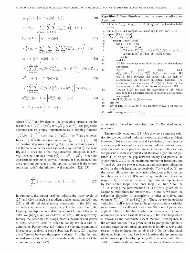
In summary, the master problem adjusts the water-levels of(25) and (26) through the gradient update equations (31) and(32) until all individual power constraints of the BSs andthe relays are satisfied, respectively. On the other hand, theLagrange multipliers in update equations (33) and (34) act asextra weightings and water-levels in (25)-(28), respectively,forcing the scheduler to assign more subcarriers and powerto delay-sensitive users in order to satisfy the data rate re-quirements. Furthermore, (35) limits the maximum amount ofinterference received in each subcarrier. Finally, (29) reducesthe difference between the capacity of user 𝑘 in the first andsecond time slots, which corresponds to the selection of theminimum capacity in (7).
Algorithm 1 Semi-Distributed Iterative Resource AllocationAlgorithm
1: Initialize 𝐿𝑚𝑎𝑥, 𝝀, 𝜸, 𝝁, 𝝂, 𝜽, 𝜹, 𝜼, and set iteration index𝑛 = 0
2: Initialize 𝒫𝑛 and compute 𝒮𝑛 according to (28) for 𝑛 = 03: repeat {Outer Loop}4: for 𝑖 = 1 to 𝑛𝐹 do5: repeat {Inner Loop}6: for 𝑝 = 1 to 𝑃 do7: for 𝑡 = 1 to 2 do8: Calculate 𝑃 (𝑡,𝑘)∗
𝐵𝑝,𝑅𝑚,𝑝(𝑖) and 𝑃
(𝑡,𝑘)∗𝑅𝑚,𝑝
(𝑖), ∀𝑘 ∈ 𝒰𝑚,𝑝,according to (25) and (26), respectively.
9: end for10: end for11: All BSs and relays transmit pilot signals on the assigned
subcarrier.12: Active users feed back
𝜃(𝑡,𝑏)𝑞,𝑔 (𝑖)(𝑠
(𝑡,𝑏)𝑞,𝑔 (𝑖)𝑙
(𝑏)𝑅𝑚,𝑝
∣𝐻(𝑏)𝑅𝑚,𝑝
(𝑖)∣2) to their BSand all BSs exchange the values with the help ofa centralized unit through an optical backhaul. Thecentralized unit calculates Ω(𝑡,𝑘)(𝑖) in (26) for theactive users and distributes the solution to each BS.
13: Update 𝒮𝑛(𝑖) for each BS according to (28) whileassuming the subcarrier allocation in other cells remainsunchanged.
14: until 𝒫𝑛(𝑖) and 𝒮𝑛(𝑖) converge15: end for16: BS updates 𝝀, 𝜸, 𝝁, 𝜽, 𝜹, 𝜼 according to (29)-(35) and set
𝑛 = 𝑛+ 117: until convergence or 𝑛 = 𝐿𝑚𝑎𝑥
E. Semi-Distributed Iterative Algorithm for Practical Imple-mentation
Theoretically, equations (25)-(35) provide a complete solu-tion for the considered multi-cell resource allocation problem.However, (26) involves non-causal knowledge of the resourceallocation policies in other cells due to multi-cell interference,which is a hurdle for practical implementation. In this section,we present a semi-distributed and iterative algorithm (Algo-rithm 1) to bridge the gap between theory and practice. InAlgorithm 1, 𝐿𝑚𝑎𝑥 is the maximum number of iterations, and𝒫𝑛 and 𝒮𝑛 are the power allocation and subcarrier allocationpolicy in the 𝑛th iteration, respectively. 𝒫𝑛(𝑖) and 𝒮𝑛(𝑖) arethe power allocation and subcarrier allocation policy vectorsin subcarrier 𝑖 for all BSs and relays in the 𝑛th iteration,respectively. The overall iterative algorithm is implementedby two nested loops. The inner loop, i.e., line 5 to line14, is solving the maximization in (18) for a given set ofLagrange multipliers for subcarrier 𝑖. In line 8, we keep thesubcarrier allocation in subcarrier 𝑖 in other cells fixed andoptimize 𝑃 (𝑡,𝑘)
𝐵𝑝,𝑅𝑚,𝑝(𝑖) and 𝑃 (𝑡,𝑘)
𝑅𝑚,𝑝(𝑖). Then, we use the updated
variables in cell 𝑝 and optimize the power allocation variablesin subcarrier 𝑖 for cell 𝑝+1, and so on. The same logic is alsoapplied in line 13. In other words, a multi-variable function isoptimized over each variable iteratively in the inner loop whichis known as the coordinate ascent method. Convergence tothe optimal solution for a given set of Lagrange multipliers isensured since the optimization problem is jointly concave withrespect to the optimization variables [24]. On the other hand,the outer loop, i.e., line 3 to line 17, solves the minimizationof the master problem by updating the Lagrange multipliers.Table I illustrates the required information exchange between

2254 IEEE TRANSACTIONS ON WIRELESS COMMUNICATIONS, VOL. 10, NO. 7, JULY 2011
32
14
56
7
109
811
1213
14
1716
1518
1920
21
2423
2225
2627
28
3130
2932
3334
3538
3736
39
4041
42
4544
4346
4748
49
Fig. 3. A multi-cell networks with 49 cells which share the same bandwidthℬ. The shaded central part is the cluster of 𝑃 = 7 coordinated cells.
the different entities of the network for solving the mas-ter problem and the subproblems with the proposed semi-distributed iterative algorithm.
V. RESULTS AND DISCUSSIONS
In this section, we evaluate the system performance usingsimulations. A multi-cell system with 49 cells is consideredwhere the central cluster of 𝑃 = 7 cells are coordinated asshown in Figure 3. Each coordinated cell is modeled as twoconcentric ring-shaped discs where the outer boundary has aradius of 2 km and the inner boundary a radius of 1 km, cf.Figure 1. There are 𝑀 = 21 relay stations in the cluster andeach cell has 𝑁 = 𝑀
𝑃 = 217 = 3 relays which are equally
distributed at the inner cell boundary in each cell for assistingthe transmission. There are 𝐾/𝑃 active cell edge users uni-formly distributed in the outer ring of each cell. The numberof subcarriers is 𝑛𝐹 = 128 with carrier center frequency2.5 GHz, bandwidth ℬ = 5 MHz, and 𝑤(𝑘) = 1, ∀𝑘. Eachsubcarrier has a bandwidth of 39 kHz and a noise variance of𝑁0 = −128 dBm. The 3GPP path loss model is used [25].The small scale fading coefficients of the BS-to-relay linksare generated as independent and identically distributed (i.i.d.)Rician random variables with Rician factor 𝜅 = 6 dB, whilethe small scale fading coefficients of the relay-to-user links arei.i.d. Rayleigh fading. For simplicity, log-normal shadowing isignored in the simulations, since its impact on the performanceof cell edge users is small compared to the impact of path loss.Since not all BSs are coordinated, we model the uncoordinatedmulti-cell interference as part of the noise variance 𝜎2𝑧 [16].We assume that the maximum transmit power per cell is 𝑃𝑇and each transmission device, i.e., BS or relay, has a maximumtransmit power 𝑃𝑅𝑇 = 𝑃𝐵𝑇 = 𝑃𝑇
𝑁+1 . The average weightedsystem throughput is obtained by counting the number ofpackets which are successfully decoded by the users averagedover both macroscopic (path loss) and microscopic (multipath)fading. Unless further specified, the number of iterations is
20 25 30 35 40 45 50 55 600
0.1
0.2
0.3
0.4
0.5
0.6
0.7
0.8
0.9
1
Maximum interference temperature to noise ratio
Nor
mal
ized
per
form
ance
of t
he p
ropo
sed
algo
rithm
PT= 35 dBm, K=420 users, 20 iteartions
PT= 35 dBm, K=315 users, 20 iteartions
PT= 35 dBm, K=210 users, 20 iteartions
PT= 40 dBm, K=420 users, 20 iteartions
PT= 40 dBm, K=315 users, 20 iteartions
PT= 40 dBm, K=210 users, 20 iteartions
Optimal Performance
PT = 35 dBm
K= 210, 315, 420users
PT = 40 dBm
K= 210, 315, 420users
I2z(dB)σ
Fig. 4. The normalized performance of the proposed algorithm versus themaximum interference-temperature-to-noise ratio 𝐼
𝜎2𝑧
for different values of𝑃𝑇 and different numbers of users 𝐾 with 𝑃 = 7 coordinated cells and𝑀 = 21 relays. The y-axis is normalized by the performance of the optimalcentralized algorithm.
defined as the product of the number of inner loops and thenumber of outer loops in Algorithm 1.
A. System Throughput versus Maximum Interference Temper-ature 𝐼
In this section, we focus on the impact of the value of𝐼 on the system performance. As can be seen from SectionIV-A, the interference temperature 𝐼 , which is the key fortransforming the original problem into a convex optimiza-tion problem, plays an important role in the proposed semi-distributed algorithm. The value of 𝐼 puts a limit on themaximum transmit power from other coordinated cells bycontrolling the amount of interference temperature8. Figure 4shows the normalized performance of the proposed algorithmversus the value of 𝐼 for different 𝑃𝑇 and different numbers ofusers 𝐾 in 𝑃 = 7 coordinated BSs. The y-axis is normalizedby the optimal performance obtained by solving the originalnon-convex problem (9) using a centralized algorithm9, suchthat it demonstrates the achievable fraction of the optimalperformance. The x-axis is the interference temperature-to-noise ratio, i.e., 𝐼
𝜎2𝑧. We assume that there are always 7
delay sensitive users with data rate requirement 𝑅(𝑘) = 0.1bit/s/Hz in the coordinated cells10, 𝑘 ∈ 𝒟𝑚,𝑝, while theremaining users are non-delay sensitive. It can be seen thatfor a wide range of 𝐼
𝜎2𝑧, we can achieve more than 95%
of the optimal performance and enjoy the convexity of the
8In practice, the values of 𝐼 for implementing the proposed algorithm canbe found in an off-line manner.
9For the centralized algorithm, the centralized unit is assumed to havethe CSI of all links in the network (including the interference links) toperform subcarrier allocation and optimal power allocation by followinga similar approach as in [21]. Note, however, that the proposed semi-distributed algorithm is guaranteed to be solved in polynomial time withlinear complexity in each iteration while the original problem in (9) has anexponential complexity in 𝑀 , 𝑃 , 𝑡, and 𝑛𝐹 .
10The target cell-edge performance for 4G is around 0.1 bit/s/Hz/user [26].

NG and SCHOBER: RESOURCE ALLOCATION AND SCHEDULING IN MULTI-CELL OFDMA SYSTEMS WITH DECODE-AND-FORWARD RELAYING 2255
TABLE IQUANTIZATION TABLE FOR THE FEEDBACK/FEEDFORWARD VARIABLES
AND LAGRANGE MULTIPLIERS .
Variables Number of bits
𝑃∗(𝑡,𝑘)𝑅𝑚,𝑝
(𝑖) 6
𝜃(𝑡,𝑏)𝑞,𝑔 (𝑖)𝑠
(𝑡,𝑏)𝑞,𝑔 (𝑖)𝑙
(𝑏)𝑅𝑚,𝑝
∣𝐻(𝑏)𝑅𝑚,𝑝
(𝑖)∣2 6
𝜆𝑝, 𝛾𝑚,𝑝, 𝜇(𝑘)𝑚,𝑝, 𝜂𝑘, 𝛿𝑘 3
Ω(𝑡,𝑘)(𝑖) 6
transformed problem. Furthermore, the choice of 𝐼 is notsensitive to the number of users for a given value of 𝑃𝑇 .On the other hand, as expected, the optimal value of 𝐼 isproportional to 𝑃𝑇 since the amount of multi-cell interferenceincreases with 𝑃𝑇 ; a higher value of 𝐼 is needed to reflect theactual interference temperature.
B. Convergence of the Semi-Distributed Algorithm and Sig-naling Overhead
Figures 5 and 6 illustrate the evolution of the Lagrangemultipliers of the semi-distributed algorithm over time fordifferent transmit powers 𝑃𝑇 . The x-axis represents the num-ber of outer loop iterations and the number of inner loopiterations is set to 2. The results in Figures 5 and 6 areaveraged over 10000 independent adaptation processes whereeach adaptation process involves different realizations forthe path loss and the multipath fading. For comparison, thefigures also contain results for the realistic case where theCSI feedback, the Lagrange multipliers, and the informationexchanged between the BSs and the relays in each iterationare quantized with finite bit resoultion11. The number of bitsused for quantization of the variables in this simulation arelisted in Table I. The results show that the semi-distributedalgorithm converges fast and typically achieves 90-95% of theoptimal value within 10 outer-loop iterations. As expected,the quantization does not affect the speed of convergencesignificantly but causes a small deviation from the optimalvalue in the steady state.
Figure 7 depicts the signaling overhead versus the numberof users for both the centralized scheme and the proposedsemi-distributed algorithm. For the semi-distributed algorithm,we quantize the involved variables as shown in Table I.For the centralized scheme, all CSI and interference levelsfed back to the centralized unit are quantized with 6 bits.It can be observed from Figure 7 that the proposed semi-distributed iterative algorithm results in a significant reductionin signaling overhead compared to the centralized resource al-location algorithm, especially when the number of users in thecoordinated cells is large. However, even for a comparativelysmall number of users in the cluster (e.g.𝐾 = 50), the amountof overhead for the semi-distributed iterative algorithm is stillless than that of the centralized algorithm if the proposedalgorithm is limited to 10 iterations (product of inner and outerloop iterations). We will show in the next subsection that 10iterations are typically enough to achieve a close-to-optimalperformance.
11The quantizer was designed off-line using the Lloyd-Max algorithm.
0 2 4 6 8 10 12 14 16 18 200
500
1000
1500
2000
2500
Number of outer loop iterations
λ 1
P
T= 40 dBm without quantization
PT= 40 dBm and 3−bit quantization
PT= 40, Optimal λ
1
PT= 35 dBm without quantization
PT= 35 dBm and 3−bit quantization
PT= 35, Optimal λ
1
PT= 30 dBm without quantization
PT= 30 dBm and 3−bit quantization
PT= 30, Optimal λ
1
Fig. 5. Lagrange multiplier 𝜆1 versus number of outer loop iterations with𝐾 = 210 users and 𝑀 = 21 relays for different transmit power levels. Thereare 7 delay-sensitive users with data rate requirement 𝑅(𝑘) = 0.1 bit/s/Hz.
Remark 1: For calculation of the total amount of signallingoverhead of the proposed algorithm shown in Figure 7, we firstdefine 𝑄[⋅]𝑥 as a 𝑥 bit quantizer used to quantize the inputvariable and Δ
(𝑡,𝑏)𝑞,𝑔,𝑚,𝑝(𝑖) = 𝜃
(𝑡,𝑏)𝑞,𝑔 (𝑖)𝑠
(𝑡,𝑏)𝑞,𝑔 (𝑖)𝑙
(𝑏)𝑅𝑚,𝑝
∣𝐻(𝑏)𝑅𝑚,𝑝
(𝑖)∣2.For the proposed semi-distributed iterative algorithm, theamount of feedback required can be calculated as
𝐾 × 𝑛𝐹 ×𝑄[∣𝐻(𝑘)
𝑅𝑚,𝑝(𝑖)∣2
]6︸ ︷︷ ︸
𝐴
+Number of iterations
×{𝑄[Δ(𝑡,𝑏)𝑞,𝑔,𝑚,𝑝(𝑖)
]6× 𝑛𝐹 × 7︸ ︷︷ ︸
𝐵
𝑄[Ω(𝑡,𝑘)(𝑖)
]6× 𝑛𝐹 × 7︸ ︷︷ ︸
𝐶
+2×(𝑄[Δ(𝑡,𝑏)𝑞,𝑔,𝑚,𝑝(𝑖)
]6× 𝑛𝐹 × 7
)︸ ︷︷ ︸
𝐷
+
𝑄[𝑃
∗(𝑡,𝑘)𝑅𝑚,𝑝
(𝑖)]6× 7× 𝑛𝐹︸ ︷︷ ︸
𝐸
}, (36)
where variable 𝐴 is the CSI feedback of the relay-to-user linksfrom the relays to their home BS in the 7 cells; 𝐵 representsthe information passing from the 7 BSs to the centralized unitvia the optical backhaul; 𝐶 corresponds to the feedforwardinformation from the centralized unit to the 7 BSs; 𝐷 is thefeedback information from the users to their home BS in the 7cells; 𝐸 is the feedforward power allocation information fromthe home BS to its relays in the 7 cells.
Remark 2: To illustrate the time scale of the proposeddistributed iterative algorithm, we adopt the following assump-tions. Suppose we use part of the uplink data channel forinformation exchange purposes in a TDD system and assumebaseline scheme 1 is used in the uplink for transmission. Inbaseline scheme 1, each BS performs its own resource allo-cation and completely ignores the multi-cell interference. Forbaseline scheme 1 and the considered model parameters, theestimated average capacity of the uplink channel in each cell is

2256 IEEE TRANSACTIONS ON WIRELESS COMMUNICATIONS, VOL. 10, NO. 7, JULY 2011
0 2 4 6 8 10 12 14 16 18 200.2
0.4
0.6
0.8
1
1.2
1.4
Number of outer loop iterations
δ(1)
PT = 40 dBm, no quantization, and R(k)=0.1 bit/s/Hz
PT = 40 dBm, 3−bit quantization, and R(k)=0.1 bit/s/Hz
PT = 40 dBm, R(k)=0.1bit/s/Hz, Optimal δ(1)
PT = 35 dBm, no quantization, and R(k)=0.1 bit/s/Hz
PT = 35 dBm, 3−bit quantization, and R(k)=0.1 bit/s/Hz
PT = 35 dBm, R(k)=0.1 bit/s/Hz, Optimal δ(1)
PT = 40 dBm, no quantization, and R(k)=0.2 bit/s/Hz
PT = 40 dBm, 3−bit quantization, and R(k)=0.2 bit/s/Hz
PT = 40 dBm, R(k)=0.2 bit/s/Hz, Optimal δ(1)
PT = 35 dBm, no quantization, and R(k)=0.2 bit/s/Hz
PT = 35 dBm, 3−bit quantization, and R(k)=0.2 bit/s/Hz
PT = 35 dBm, R(k)=0.2 bit/s/Hz, Optimal δ(1)
Fig. 6. Lagrange multiplier 𝛿(1) versus number of outer loop iterations with𝐾 = 210 users and 𝑀 = 21 relays for different transmit power levels anddata rate requirements for 7 delay sensitive users.
0 100 200 300 400 500 600 700 800 900 10000
200
400
600
800
1000
1200
1400
Number of users in 7 coordinated cells
Sys
tem
sig
nalli
ng o
verh
ead
of a
ll co
ordi
nate
d ce
lls (
kilo
byte
)
Global CSI for centralized algorithmSemi−distributed algorithm and 10 iterationsSemi−distributed algorithm and 20 iterationsSemi−distributed algorithm and 30 iterations
Fig. 7. Signaling overhead versus number of users for 𝑛𝐹 = 128, 𝑃 = 7coordinated cells, 𝑀 = 21 relays, and 7 delay-sensitive users with data raterequirement 𝑅(𝑘) = 0.1 bit/s/Hz.
around 0.4 bit/s/Hz/cell12, as can be observed in Figure 8. Thetotal amount of information exchange for 20 and 10 iterationsis 672000 bits and 403200 bits for 7 cells with a total of 𝐾 =175 users, respectively, cf. Figure 7. Assuming all the informa-tion is conveyed by the bottleneck wireless links, the executiontime for 20 and 10 iterations of the proposed algorithm areupper bounded by 672000 bits/(0.4 bit/s/Hz/cell × 5 MHz ×7 cells) = 48 ms and 403200 bits/(0.4 bit/s/Hz/cell ×5 MHz × 7 cells) = 28 ms, respectively. Furthermore, foran OFDMA system with a central carrier frequency of 2.5GHz, the coherence time of the relay-to-user links is roughly200 ms for pedestrian users [27]. Therefore, the schedulingand resource allocation results obtained with the distributedalgorithm are still valid after 10-20 iterations.
12The wireless link capacity is the bottleneck in the feedback path of theproposed algorithm.
0 5 10 15 20 25 30 35 400
0.2
0.4
0.6
0.8
1
1.2
1.4
PT (dBm)
Ave
rage
wei
ghte
d sy
stem
thro
ughp
ut (
bit/s
/Hz/
cell)
Cetralized BSs coordiniation with optimized time slot allocationBSs coordiniation with optimized time slot allocation and 20 iteraionsBSs coordiniation with optimized time slot allocation and 10 iteraionsBSs coordiniation with optimized time slot allocation, 20 iteraions, and 6−bit quantizationCetralized BSs coordiniation with fixed time slot allocationBSs coordiniation with fixed time slot allocation and 20 iteraionsBSs coordiniation with fixed time slot allocation and 10 iteraionsBSs coordiniation with fixed time slot allocation, 20 iteraions, and 6−bit quantizationCetralized BSs coordiniation with traditional time slot allocationBSs coordiniation with traditional time slot allocation and 20 iteraionsBSs coordiniation with traditional time slot allocation and 10 iteraionsBSs coordiniation with traditional time slot allocation, 10 iteraions, and 6−bit quantizationBaseline scheme 1Baseline scheme 2
Baseline scheme 1
Baseline scheme 2
BSs coordination
Traditional time slot allocation
Optimized time slot allocation
Fixed time slot allocation
Fig. 8. Average weighted system throughput versus total transmit power percell for different resource allocation and scheduling algorithms. 𝐾 = 210users and 𝑃 = 7 coordinated BSs.
C. System Throughput versus Transmit Power
Figure 8 illustrates the average weighted system throughputversus the total transmit power in each cell 𝑃𝑇 . There are𝐾 = 210 users in the cluster and there are 7 delay sensi-tive users with data rate requirement 𝑅(𝑘) = 0.1 bit/s/Hz,𝑘 ∈ 𝒟𝑚,𝑝, while the remaining users are non-delay sensitiveand served by best effort. We are interested in studying theperformance of the proposed semi-distributed algorithm underdifferent system configurations. The value of 𝐼 in the proposedalgorithm in each simulation point is chosen such that wealways achieve more than 95% of the performance of theoptimal resource allocation and scheduling algorithm. We firstdemonstrate the performance gain achieved by the time slotallocation strategy for the proposed semi-distributed algorithmwith different system configurations, namely, BS coordinationwith optimized time slot allocation strategy (presented in themain text), BS coordination with fixed time slot allocationstrategy, and BS coordination with traditional time slot allo-cation strategy. For the BS coordination with fixed time slotallocation strategy, the cells with odd index 𝑝 employ 𝑡 = 1 forall subcarriers and the remaining cells use 𝑡 = 2 for all channelrealizations. The traditional time slot allocation strategy isrealized by assigning 𝑡 = 1 to all BSs and subcarriers. Ascan be observed, the optimized time slot allocation strategyprovides a significant power gain in the high transmit powerregime (multi-cell interference limited environment) comparedto the fixed and traditional time slot allocation strategies. Inall cases, even with only 20 iterations, the proposed semi-distributed algorithm closely approaches the performance ofthe optimal centralized scheduling algorithm. On the otherhand, the performance loss due to quantization is small which
NG and SCHOBER: RESOURCE ALLOCATION AND SCHEDULING IN MULTI-CELL OFDMA SYSTEMS WITH DECODE-AND-FORWARD RELAYING 2257
100 200 300 400 500 600 7000
0.5
1
1.5
Number of users in a cluster
Ave
rage
wei
ghte
d sy
stem
thro
ughp
ut (
bit/s
/Hz/
cell)
PT=40 dBm, R(k)=0.1 bit/s/Hz
PT=40 dBm, R(k)=0.2 bit/s/Hz
PT=30 dBm, R(k)=0.1 bit/s/Hz
PT=30 dBm, R(k)=0.2 bit/s/Hz
PT=20 dBm, R(k)=0.1 bit/s/Hz
PT=20 dBm, R(k)=0.2 bit/s/Hz
PT=10 dBm, R(k)=0.1 bit/s/Hz
PT=10 dBm, R(k)=0.2 bit/s/Hz
PT= 10 dBm
PT= 40 dBm
PT= 30 dBm
PT= 20 dBm
Fig. 9. Average weighted system throughput versus number of users in acluster with different data rate requirements and transmit power levels for theproposed semi-distributed resource allocation and scheduling algorithms.
suggests that the proposed algorithm can be implemented inpractice with finite bit resolution.
For comparison, Figure 8 also contains the performanceof two baselines schemes. As mentioned before, in baselinescheme 1, each BS performs its own resource allocation forthe DF relaying system and completely ignores the multi-cellinterference. For baseline scheme 2, interference from coor-dinated cells is completely avoided by setting the frequencyreuse factor to 1
𝑃 . In both baseline schemes, each BS is as-sumed to have the CSI of its own cell. Then, the optimal powerallocation and subcarrier allocation for these two schemes canbe calculated by equation (9)13. In the low transmit powerregime, i.e., 𝑃𝑇 < 5 dBm, baseline scheme 1 achieves asimilar performance as the proposed semi-distributed resourceallocation algorithm. This is because noise is the dominatingfactor for system performance for low transmit powers and theeffect of interference coordination is less significant. However,as the total transmit power increases, the operating point of thecluster is shifting from noise limited to interference limited.The performance of the proposed semi-distributed algorithmscales with the transmit power and achieves a substantialperformance gain compared to baseline scheme 1, since thethroughput of the latter is saturated due to strong multi-cellinterference. On the other hand, although baseline scheme 2 isable to scale with the transmit power, the proposed algorithmachieves a much higher spectral efficiency. This is due to thefact that baseline scheme 2 sacrifices spectrum efficiency toavoid multi-cell interference.
D. System Throughput versus Number of Users
Figure 9 depicts the average weighted system throughputversus the number of users with different transmit powerand user data rate requirements. The number of iterationsfor the proposed algorithm is 10. It can be observed thatthe average system throughput increases with the number of
13To solve the single-cell optimization problem, we need to set the multi-cell interference level to zero and reduce the number of coordinated cells to1.
1 2 3 4 5 6 70.2
0.4
0.6
0.8
1
1.2
1.4
1.6
Number of cells in a cluster
Ave
rage
wei
ghte
d sy
stem
thro
ughp
ut (
bit/s
/Hz/
cell)
BS coordination, P
T=40 dBm, R(k)=0.1 bit/s/Hz
BS coordination, PT=30 dBm, R(k)=0.1 bit/s/Hz
BS coordination, PT=20 dBm, R(k)=0.1 bit/s/Hz
BS coordination, PT=40 dBm, R(k)=0.2 bit/s/Hz
BS coordination, PT=30 dBm, R(k)=0.2 bit/s/Hz
BS coordination, PT=20 dBm, R(k)=0.2 bit/s/Hz
Baseline scheme 1, PT=40 dBm, R(k)=0.1 bit/s/Hz
Baseline scheme 1, PT=40 dBm, R(k)=0.2 bit/s/Hz
Performance gain
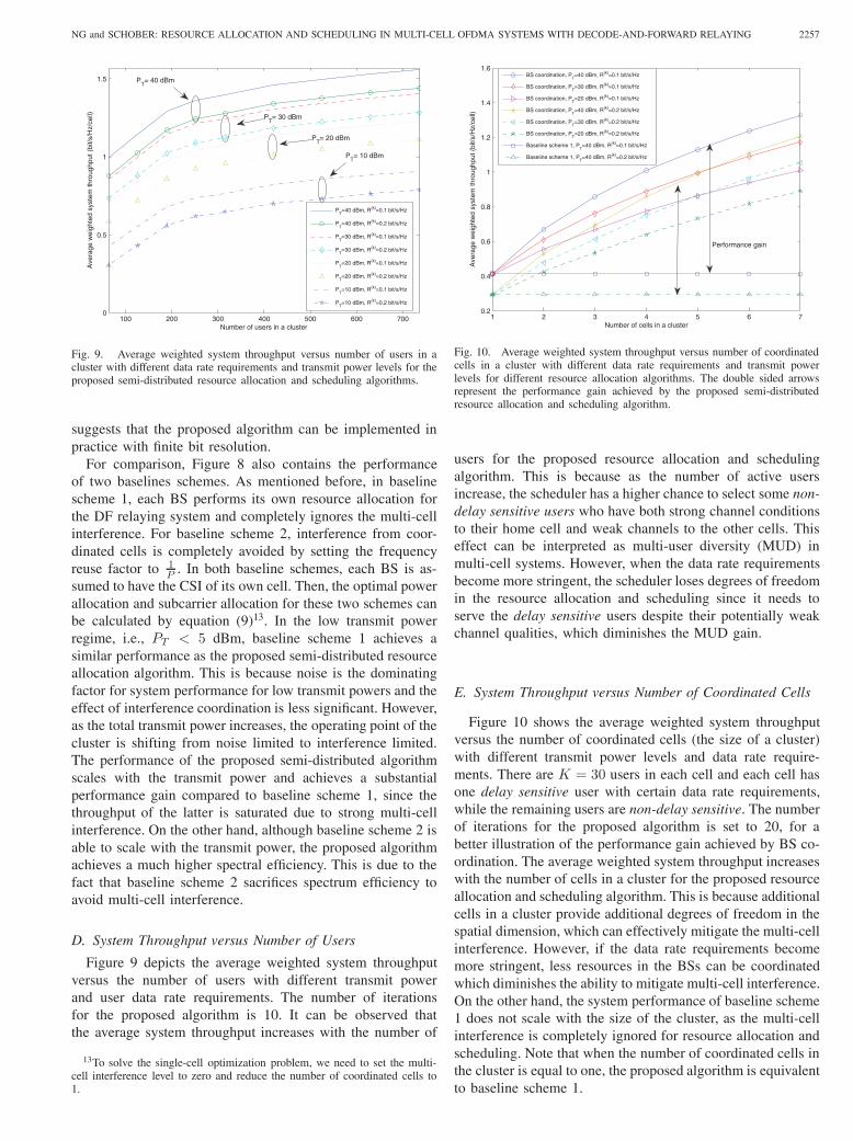
Fig. 10. Average weighted system throughput versus number of coordinatedcells in a cluster with different data rate requirements and transmit powerlevels for different resource allocation algorithms. The double sided arrowsrepresent the performance gain achieved by the proposed semi-distributedresource allocation and scheduling algorithm.
users for the proposed resource allocation and schedulingalgorithm. This is because as the number of active usersincrease, the scheduler has a higher chance to select some non-delay sensitive users who have both strong channel conditionsto their home cell and weak channels to the other cells. Thiseffect can be interpreted as multi-user diversity (MUD) inmulti-cell systems. However, when the data rate requirementsbecome more stringent, the scheduler loses degrees of freedomin the resource allocation and scheduling since it needs toserve the delay sensitive users despite their potentially weakchannel qualities, which diminishes the MUD gain.
E. System Throughput versus Number of Coordinated Cells
Figure 10 shows the average weighted system throughputversus the number of coordinated cells (the size of a cluster)with different transmit power levels and data rate require-ments. There are 𝐾 = 30 users in each cell and each cell hasone delay sensitive user with certain data rate requirements,while the remaining users are non-delay sensitive. The numberof iterations for the proposed algorithm is set to 20, for abetter illustration of the performance gain achieved by BS co-ordination. The average weighted system throughput increaseswith the number of cells in a cluster for the proposed resourceallocation and scheduling algorithm. This is because additionalcells in a cluster provide additional degrees of freedom in thespatial dimension, which can effectively mitigate the multi-cellinterference. However, if the data rate requirements becomemore stringent, less resources in the BSs can be coordinatedwhich diminishes the ability to mitigate multi-cell interference.On the other hand, the system performance of baseline scheme1 does not scale with the size of the cluster, as the multi-cellinterference is completely ignored for resource allocation andscheduling. Note that when the number of coordinated cells inthe cluster is equal to one, the proposed algorithm is equivalentto baseline scheme 1.

2258 IEEE TRANSACTIONS ON WIRELESS COMMUNICATIONS, VOL. 10, NO. 7, JULY 2011
VI. CONCLUSION
In this paper, we have formulated the resource alloca-tion and scheduling design for multi-cell OFDMA systemswith DF relaying as a mixed non-convex and combinato-rial optimization problem, in which multi-cell interferenceand heterogenous user data rate requirements are taken intoconsideration. For improved interference mitigation, we haveincorporated an effective time slot allocation strategy into theproblem formulation. By imposing an additional interferencetemperature constraint and relaxing the subcarrier allocationconstraints, the considered problem has been transformedinto a convex problem. An iterative semi-distributed resourceallocation algorithm with closed-form power and subcarrierallocation policies has been derived via dual decompositionand requires only local CSI at each BS. Simulation results haveshown that the proposed algorithm approaches the optimalperformance in a small number of iterations even if theinformation exchanged between the different nodes of thenetwork is quantized, which confirms the practicality of theproposed scheme.
REFERENCES
[1] G. Song and Y. Li, “Utility-based resource allocation and schedulingin OFDM-based wireless broadband networks,” IEEE Commun. Mag.,vol. 43, pp. 127–134, Dec. 2005.
[2] G. Song, Y. Li, and L. J. Cimini, “Joint channel-and queue-awarescheduling for multiuser diversity in wireless OFDMA networks,” IEEETrans. Commun., vol. 57, pp. 2109–2121, July 2009.
[3] Y. Cui, V. K. N. Lau, and R. Wang, “Distributive subband allocation,power and rate control for relay-assisted OFDMA cellular system withimperfect system state knowledge,” IEEE Trans. Wireless Commun.,vol. 8, pp. 5096–5102, Oct. 2009.
[4] H.-X. Li, H. Yu, H.-W. Luo, J. Guo, and C. Li, “Dynamic subchanneland power allocation in OFDMA-based DF cooperative relay networks,”in Proc. IEEE Global Telecommun. Conf., Dec. 2008, pp. 1–5.
[5] W. Nam, W. Chang, S.-Y. Chung, and Y. H. Lee, “Transmit optimiza-tion for relay-based cellular OFDMA systems,” in Proc. IEEE Intern.Commun. Conf., June 2007, pp. 5714–5719.
[6] L. Weng and R. D. Murch, “Cooperation strategies and resourceallocations in multiuser OFDMA systems,” IEEE Trans. Veh. Technol.,vol. 58, pp. 2331–2342, June 2009.
[7] T. Wang, A. Cano, G. B. Giannakis, and J. N. Laneman, “High-performance cooperative demodulation with decode-and-forward re-lays,” IEEE Trans. Commun., vol. 55, pp. 1427–1438, July 2007.
[8] “Downlink inter-cell interference co-ordination/avoidance–evaluation offrequency reuse,” 3GPP TSG-RAN WG1 contribution R1-061374, tech.rep., 2006.
[9] J. G. Andrews, “Interference cancellation for cellular systems: a con-temporary overview,” IEEE Wireless Commun. Mag., vol. 12, pp. 19–29,Apr. 2005.
[10] J. G. Andrews, W. Choi, and R. W. Heath, “Overcoming interferencein spatial multiplexing MIMO cellular networks,” IEEE Trans. WirelessCommun., vol. 14, pp. 95–104, Dec. 2007.
[11] O. Simeone, O. Somekh, Y. Bar-Ness, and U. Spagnolini, “Uplinkthroughput of TDMA cellular systems with multicell processing andamplify-and-forward cooperation between mobiles,” IEEE Trans. Wire-less Commun., vol. 6, pp. 2942–2951, Aug. 2007.
[12] O. Somekh, O. Simeone, H. V. Poor, and S. Shamai, “Cellular systemswith full-duplex amplify-and-forward relaying and cooperative base-stations,” in Proc. IEEE Intern. Sympos. on Inform. Theory, June 2007,pp. 16–20.
[13] O. Somekh, O. Simeone, Y. Bar-Ness, A. M. Haimovich, and S. Shamai,“Cooperative multicell zero-forcing beamforming in cellular downlinkchannels,” IEEE Trans. Inf. Theory, vol. 55, pp. 3206–3219, July 2009.
[14] A. Gjendemsj, D. Gesbert, G. E. Oien, and S. G. Kiani, “Binary powercontrol for sum rate maximization over multiple interfering links,” IEEETrans. Wireless Commun., vol. 7, pp. 3164–3173, Aug. 2008.
[15] Z. Liang, Y. H. Chew, and C. C. Ko, “A linear programming solutionto subcarrier, bit and power allocation for multicell OFDMA systems,”in Proc. IEEE Wireless Commun. and Networking Conf., Apr. 2008, pp.1273–1278.
[16] L. Venturino, N. Prasad, and X. Wang, “Coordinated scheduling andpower allocation in downlink multicell OFDMA networks,” IEEE Trans.Veh. Technol., vol. 58, pp. 2835–2848, July 2009.
[17] H. A. Suraweera, R. H. Y. Louie, Y. Li, G. K. Karagiannidis, andB. Vucetic, “Two hop amplify-and-forward transmission in mixedRayleigh and Rician fading channels,” IEEE Commun. Lett., vol. 13,pp. 227–229, Apr. 2009.
[18] G. Song and Y. Li, “Cross-layer optimization for OFDM wirelessnetworks–part II: algorithm development,” IEEE Trans. Wireless Com-mun., vol. 4, pp. 625–634, Mar. 2005.
[19] “Report of the Spectrum Ffficiency Working,” FCC Spectrum PolicyTask Force, tech. rep., Nov 2002. Available: http://www.fcc.gov/sptf/reports.html.
[20] C. Y. Wong, R. S. Cheng, K. B. Lataief, and R. D. Murch, “MultiuserOFDM with adaptive subcarrier, bit, and power allocation,” IEEE J. Sel.Areas Commun., vol. 17, pp. 1747–1758, Oct. 1999.
[21] W. Yu and R. Lui, “Dual methods for nonconvex spectrum optimizationof multicarrier systems,” IEEE Trans. Commun., vol. 54, pp. 1310–1321,July 2006.
[22] S. Boyd and L. Vandenberghe, Convex Optimization. Cambridge Uni-versity Press, 2004.
[23] S. Boyd, L. Xiao, and A. Mutapcic, “Subgradient methods,” notes forEE392o Stanford University Autumn, 2003-2004.
[24] D. P. Bertsekas, Nonlinear Programming, 2nd edition. Athena Scientific,1999.
[25] “Spatial channel model for multiple input multiple output (MIMO)simulations,” 3GPP TR 25.996 V7.0.0 (2007-06), tech. rep.
[26] M. Rumney, LTE and the Evolution to 4G Wireless: Design andMeasurement Challenges, 1st edition. Agilent Technologies, 2009.
[27] J. G. Andrews, A. Ghosha, and R. Muhamed, Fundamentals of WiMAX:Understanding Broadband Wireless Networking, 1st edition. PrenticeHall PTR, 2007.
Derrick Wing Kwan Ng (S’06) received thebachelor degree with First class honor and Masterof Philosophy (M. Phil.) degree in electronic en-gineering from the Hong Kong University of Sci-ence and Technology (HKUST) in 2006 and 2008,respectively. He is currently working toward thePh.D. degree in the University of British Columbia(UBC). His research interests include cross-layeroptimization for wireless communication systems,resource allocation in OFDMA wireless system andcommunication theory. He received the Best Paper
Award at the IEEE Third International Conference on Communications andNetworking in China 2008. He was awarded the IEEE Student Travel Grantsfor attending the IEEE WCNC 2010 and the IEEE ICC 2011. He wasalso the recipient of the 2009 Four Year Doctoral Fellowship from theUBC, Sumida & Ichiro Yawata Foundation Scholarship in 2008 and R&DExcellence scholarship from the Center for Wireless Information Technologyin the HKUST in 2006.
Robert Schober (M’01, SM’08, F’10) was bornin Neuendettelsau, Germany, in 1971. He receivedthe Diplom (Univ.) and the Ph.D. degrees in elec-trical engineering from the University of Erlangen-Nuermberg in 1997 and 2000, respectively. FromMay 2001 to April 2002 he was a PostdoctoralFellow at the University of Toronto, Canada, spon-sored by the German Academic Exchange Service(DAAD). Since May 2002 he has been with theUniversity of British Columbia (UBC), Vancouver,Canada, where he is now a Full Professor and
Canada Research Chair (Tier II) in Wireless Communications. His researchinterests fall into the broad areas of Communication Theory, Wireless Com-munications, and Statistical Signal Processing.
Dr. Schober received the 2002 Heinz Maier-Leibnitz Award of the GermanScience Foundation (DFG), the 2004 Innovations Award of the VodafoneFoundation for Research in Mobile Communications, the 2006 UBC KillamResearch Prize, the 2007 Wilhelm Friedrich Bessel Research Award ofthe Alexander von Humboldt Foundation, and the 2008 Charles McDowellAward for Excellence in Research from UBC. In addition, he received bestpaper awards from the German Information Technology Society (ITG), theEuropean Association for Signal, Speech and Image Processing (EURASIP),IEEE ICUWB 2006, the International Zurich Seminar on Broadband Com-munications, and European Wireless 2000. Dr. Schober is also the AreaEditor for Modulation and Signal Design for the IEEE TRANSACTIONS ON
COMMUNICATIONS.