224.1r-93 causes, evaluation and repair of cracks in ... · 302.1r, aci 305r). these measures...
TRANSCRIPT

ACI 224.1R-93
Causes, Evaluation and Repair of Reapproved 1998
Cracks in Concrete Structures
Reported by ACI Committee 224
Grant T. H&orsen*tChairman
Randall W. PostonSecretary
Peter BarlowtFlorian BarthtAlfred G. Bishara*Howard L BoggsMerle E. BrandeeDavid Darwin*Fouad H. Fouad
David W. FowlergPeter Gergely*Wii HansenM. Nadim HassounTony C. Iiu$Edward G. NawyHarry M. Palmbaum
Keith A. PashinaAndrew Scanlon$Ernest K. SchraderWimal SuarisLewis H. TuthillZenon A. Zielinski
* Contributing Authort Member of Task Group which prepared these revisions$ Principal Author0 Chairman of Task Group which prepared these revisionsNote: Associate members Masayatsu Ohtsu, Robert L. Yuan, and Consulting Member LeRoy Lutz contribute to the revision of this document.
The causes of cracks in concrete structures are summarized The proce-dures used to evaluate cracking in concrete and the principal techniques forthe repair of cracks are presented The key methods of crack repair arediscussed and guidance is provided for their proper application
Keywords: autogenous healing; beams (supports); cement-aggregate reactions;concrete construction; concrete pavements; concrete slabs; concretes; consol-idation; corrosion; cracking (fracturing); drilling; drying shrinkage; epoxy resins;evaluation; failure; grouting, heat of hydration; mass concrete; methacrylates; mixproportioning; plastics, polymers and resins; precast concrete; prestressedconcrete; reinforced concrete; repairs;resurfacing; sealing settlement (structural);shrinkage; specifications; structural design; tension; thermal expansion; volumechange.
C O N T E N T S
Preface, pg. 224.1R-1
Chapter 1-Causes and control of cracking, pg. 224.1R-21.1-Introduction1.2-Cracking of plastic concrete1.3-Cracking of hardened concrete
ACI Committee Reports, Guides, Standard Practices, andCommentaries are intended for guidance in designing, plan-ning, executing, or inspecting construction and in preparingspecifications. References to these documents shall not bemade in the Project Documents. If items found in thesedocuments are desired to be a part of the Project Docu-ments, they should be phrased in mandatory language andincorporated into the Project Documents.
224.1R
Chapter 2-Evaluation of cracking, pg. 224.1R-92.1-Introduction2.2-Determination of location and extent of concrete
cracking2.3-Selection of repair procedures
Chapter 3-Methods of crack repair, pg. 224.1R-133.1-Introduction3.2-Epoxy injection3.3-Routing and sealing3.4-Stitching3.5-Additional reinforcement3.6-Drilling and plugging3.7-Gravity filling3.8-Grouting3.9-Drypacking3.10-Crack arrest3.11-Polymer impregnation3.12-Overlay and surface treatments3.13-Autogenous healing
AC1 224.1R-93 supersedes ACI 224.1R-90 and became effective September 1,1993.
Copyright d 1993, American Concrete Institute.All rights reserved including rights of reproduction and use in any form or by
any means, including the making of copies by any photo process, or by any elec-tronic or mechanical devices, printed or written or oral, or recording for soundor visual reproduction or for use in any knowledge or retrieval system or device,unless permission in writing is obtained from the copyright proprietors.
-l

224.1R-2 ACI COMMITTEE REPORT
Chapter 4-Summary, pg. 224.lR-19
Acknowledgment, pg. 224.1R-19
Chapter 5-References, pg. 224.1R-205.1-Recommended references5.2-Cited references
PREFACE
Cracks in concrete have many causes. They may affectappearance only, or they may indicate significant struc-tural distress or a lack of durability. Cracks may repre-sent the total extent of the damage, or they may point toproblems of greater magnitude. Their significance de-pends on the type of structure, as well as the nature ofthe cracking. For example, cracks that are acceptable forbuildings may not be acceptable in water-retaining struc-tures.
The proper repair of cracks depends on knowing thecauses and selecting the repair procedures that take thesecauses into account; otherwise, the repair may only betemporary. Successful long-term repair procedures mustattack the causes of the cracks as well as the cracksthemselves.
To aid the practitioner in pinpointing the best solutionto a cracking problem, this report discusses the causes,evaluation procedures, and methods of repair of cracksin concrete. Chapter 1 presents a summary of the causesof cracks and is designed to provide background for theevaluation of cracks. Chapter 2 describes evaluation tech-niques and criteria. Chapter 3 describes the methods ofcrack repair and includes a discussion of a number oftechniques that are available. Many situations will requirea combination of methods to fully correct the problem.
Preface to the 1991 Revision
Following the initial publication of ACI 224.1R in1985, the Committee processed two minor revisions. Onerevision, published as ACI 224.lR-89 simply updated theformat of recommended references. A second minor revi-sion contained minor technical revisions and editorialcorrections in the document, and added a new section toChapter 3, regarding the use of high-molecular-weightmethacrylates as sealer/healers.
During 1990 a Committee 224 Task Croup reviewedthe document and recommended the revisions containedherein. Chapter 1 has been altered in only minor detail.The introduction to Chapter 2 has been revised exten-sively, and additional minor revisions have been made tothe rest of the Chapter. In Chapter 3, the section onrouting and sealing has been rewritten to include flexiblesealing and overbanding of cracks, and it is updated toreflect current materials and construction practices. Sec-tion 3.2 on epoxy injection has been revised to be some-what more general and reflect current practice. The for-
mer section on high-molecular-weight methacrylates hasbeen moved to Section 3.7 and retitled “Gravity Filling.”This recognizes the point that “high-molecular-weightmethacrylate” is a material, and not a method. Refer-ences are presented in Chapter 5; citations throughoutthe text have been revised to employ the author/dateformat. Several new references have been added.
Additional revision of the report is ongoing. Commit-tee 224 invites comment from the readers and users ofthis report on new developments, or alternate viewpointson the Causes, Evaluation, and Repair of Cracks in Con-crete Structures.
CHAPTER 1-CAUSES AND CONTROLOF CRACKING
1.1-IntroductionThis chapter presents a brief summary of the causes of
cracks and means for their control. Cracks are categor-ized as occurring either in plastic concrete or hardenedconcrete (Kelly 1981; Price 1982). In addition to the in-formation provided here, further details are presented inACI 224R and articles by Carlson et al. (1979), Kelly(1981), Price (1982),, and Abdun-Nur (1983). Additionalreferences are cited throughout the chapter.
1.2-Cracking of plastic concrete1.2.1 Plastic shrinkage cracking-"Plastic shrinkage
cracking (Fig. 1.1) occurs...when subjected to a veryrapid loss of moisture caused by a combination of factorswhich include air and concrete temperatures, relativehumidity, and wind velocity at the surface of the con-crete. These factors can combine to cause high rates ofsurface evaporation in either hot or cold weather.”
When moisture evaporates from the surface of freshlyplaced concrete faster than it is replaced by bleed water,the surface concrete shrinks. Due to the restraint pro-vided by the concrete below the drying surface layer, ten-sile stresses develop in the weak, stiffening plastic con-crete, resulting in shallow cracks of varying depth which
----
Fig. 1.1-Typical plastic shrinkage cracking (Price 1982)

CAUSES, EVALUATION AND REPAIR OF CRACKS 224.1R-3
Fig. 1.3-Settlement cracking as a function of bar size,slump and cover (Dakhil et al. 1975)
may form a random, polygonal pattern, or may appear asessentially parallel to one another. These cracks are oftenfairly wide at the surface. They range from a few inchesto many feet in length and are spaced from a few inchesto as much as 10 ft (3 m) apart. Plastic shrinkage cracksbegin as shallow cracks but can become full-depth cracks.
Since plastic shrinkage cracking is due to a differentialvolume change in the plastic concrete, successful controlmeasures require a reduction in the relative volumechange between the surface and other portions of theconcrete.
Steps can be taken to prevent a rapid moisture lossdue to hot weather and dry winds (ACI 224R, ACI302.1R, ACI 305R). These measures include the use offog nozzles to saturate the air above the surface and theuse of plastic sheeting to cover the surface betweenfinishing operations. Windbreaks to reduce the wind
velocity and sunshades to reduce the surface temperatureare also helpful, and it is good practice to schedule flatwork after the windbreaks have been erected.
1.2.2 Settlement cracking - After initial placement,vibration, and finishing, concrete has a tendency to con-tinue to consolidate. During this period, the plastic con-crete may be locally restrained by reinforcing steel, aprior concrete placement, or formwork. This local re-straint may result in voids and/or cracks adjacent to therestraining element (Fig. 1.2). When associated with rein-forcing steel, settlement cracking increases with in-creasing bar size, increasing slump, and decreasing cover(Dakhil et al. 1975). This is shown in Fig. 1.3 for alimited range of these variables. The degree of settlementcracking may be intensified by insufficient vibration orby the use of leaking or highly flexible forms.
Form design (ACI 347R) and vibration (and revibra-tion), provision of a time interval between the placementof concrete in columns or deep beams and the placementof concrete in slabs and beams (ACI 309.2R), the use ofthe lowest possible slump, and an increase in concretecover will reduce settlement cracking.
Fig. 1.2-Crack formed due to obstructed settlement (Price1982)
80
60
40
20
Bar Size
~~
\Slump
0 I I I
I ’Cover (19mm) 1” (25mm) 1 1/2" (38mm) 2” (51mm)
Bar Size : No.4 (13mm) No.5 (16mm) No.6 (19mm)
Slump: 2” (51mm) 3” (76mm) 4” (102mm)
1.3-Cracking of hardened concrete1.3.1 Drying shrinkage-A common cause of cracking
in concrete is restrained drying shrinkage. Dryingshrinking is caused by the loss of moisture from thecement paste constituent, which can shrink by as much as1 percent. Fortunately, aggregate provides internal re-straint that reduces the magnitude of this volume changeto about 0.06 percent. On wetting, concrete tends toexpand.
These moisture-induced volume changes are a charac-teristic of concrete. If the shrinkage of concrete couldtake place without restraint, the concrete would notcrack. It is the combination of shrinkage and restraint(usually provided by another part of the structure or bythe subgrade) that causes tensile stresses to develop.When the tensile strength of concrete is exceeded, it willcrack. Cracks may propagate at much lower stresses thanare required to cause crack initiation.
In massive concrete elements, tensile stresses arecaused by differential shrinkage between the surface andthe interior concrete. The larger shrinkage at the surfacecauses cracks to develop that may, with time, penetratedeeper into the concrete.
The magnitude of the tensile stresses induced by vol-ume change is influenced by a combination of factors, in-cluding the amount of shrinkage, the degree of restraint,the modulus of elasticity, and the amount of creep. Theamount of drying shrinkage is influenced mainly by theamount and type of aggregate and the water content ofthe mix. The greater the amount of aggregate, thesmaller the amount of shrinkage (Pickett 1956). Thehigher the stiffness of the aggregate, the more effectiveit is in reducing the shrinkage of the concrete (i.e., theshrinkage of concrete containing sandstone. aggregatemay be more than twice that of concrete with granite,
224.1R-4 ACI COMMITTEE REPORT
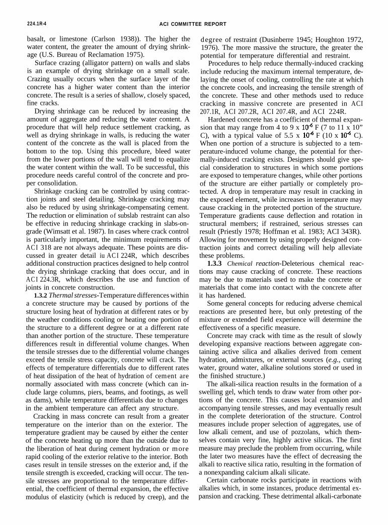
basalt, or limestone (Carlson 1938)). The higher thewater content, the greater the amount of drying shrink-age (U.S. Bureau of Reclamation 1975).
Surface crazing (alligator pattern) on walls and slabsis an example of drying shrinkage on a small scale.Crazing usually occurs when the surface layer of theconcrete has a higher water content than the interiorconcrete. The result is a series of shallow, closely spaced,fine cracks.
Drying shrinkage can be reduced by increasing theamount of aggregate and reducing the water content. Aprocedure that will help reduce settlement cracking, aswell as drying shrinkage in walls, is reducing the watercontent of the concrete as the wall is placed from thebottom to the top. Using this procedure, bleed waterfrom the lower portions of the wall will tend to equalizethe water content within the wall. To be successful, thisprocedure needs careful control of the concrete and pro-per consolidation.
Shrinkage cracking can be controlled by using contrac-tion joints and steel detailing. Shrinkage cracking mayalso be reduced by using shrinkage-compensating cement.The reduction or elimination of subslab restraint can alsobe effective in reducing shrinkage cracking in slabs-on-grade (Wimsatt et al. 1987). In cases where crack controlis particularly important, the minimum requirements ofAC I 318 are not always adequate. These points are dis-cussed in greater detail iu AC I 224R, which describesadditional construction practices designed to help controlthe drying shrinkage cracking that does occur, and inAC I 224.3R, which describes the use and function ofjoints in concrete construction.
1.3.2 Thermal stresses-Temperature differences withina concrete structure may be caused by portions of thestructure losing heat of hydration at different rates or bythe weather conditions cooling or heating one portion ofthe structure to a different degree or at a different ratethan another portion of the structure. These temperaturedifferences result in differential volume changes. Whenthe tensile stresses due to the differential volume changesexceed the tensile stress capacity, concrete will crack. Theeffects of temperature differentials due to different ratesof heat dissipation of the heat of hydration of cement arenormally associated with mass concrete (which can in-clude large columns, piers, beams, and footings, as wellas dams), while temperature differentials due to changesin the ambient temperature can affect any structure.
Cracking in mass concrete can result from a greatertemperature on the interior than on the exterior. Thetemperature gradient may be caused by either the centerof the concrete heating up more than the outside due tothe liberation of heat during cement hydration or morerapid cooling of the exterior relative to the interior. Bothcases result in tensile stresses on the exterior and, if thetensile strength is exceeded, cracking will occur. The ten-sile stresses are proportional to the temperature differ-ential, the coefficient of thermal expansion, the effectivemodulus of elasticity (which is reduced by creep), and the
degree of restraint (Dusinberre 1945; Houghton 1972,1976). The more massive the structure, the greater thepotential for temperature differential and restraint.
Procedures to help reduce thermally-induced crackinginclude reducing the maximum internal temperature, de-laying the onset of cooling, controlling the rate at whichthe concrete cools, and increasing the tensile strength ofthe concrete. These and other methods used to reducecracking in massive concrete are presented in ACI207.1R, ACI 207.2R, ACI 207.4R, and ACI 224R.
Hardened concrete has a coefficient of thermal expan-sion that may range from 4 to 9 x lOA F (7 to 11 x 10”C), with a typical value of 5.5 x lOA F (10 x lOA C).When one portion of a structure is subjected to a tem-perature-induced volume change, the potential for ther-mally-induced cracking exists. Designers should give spe-cial consideration to structures in which some portionsare exposed to temperature changes, while other portionsof the structure are either partially or completely pro-tected. A drop in temperature may result in cracking inthe exposed element, while increases in temperature maycause cracking in the protected portion of the structure.Temperature gradients cause deflection and rotation instructural members; if restrained, serious stresses canresult (Priestly 1978; Hoffman et al. 1983; ACI 343R).Allowing for movement by using properly designed con-traction joints and correct detailing will help alleviatethese problems.
1.3.3 Chemical reaction-Deleterious chemical reac-tions may cause cracking of concrete. These reactionsmay be due to materials used to make the concrete ormaterials that come into contact with the concrete afterit has hardened.
Some general concepts for reducing adverse chemicalreactions are presented here, but only pretesting of themixture or extended field experience will determine theeffectiveness of a specific measure.
Concrete may crack with time as the result of slowlydeveloping expansive reactions between aggregate con-taining active silica and alkalies derived from cementhydration, admixtures, or external sources (e.g., curingwater, ground water, alkaline solutions stored or used inthe finished structure.)
The alkali-silica reaction results in the formation of aswelling gel, which tends to draw water from other por-tions of the concrete. This causes local expansion andaccompanying tensile stresses, and may eventually resultin the complete deterioration of the structure. Controlmeasures include proper selection of aggregates, use oflow alkali cement, and use of pozzolans, which them-selves contain very fine, highly active silicas. The firstmeasure may preclude the problem from occurring, whilethe later two measures have the effect of decreasing thealkali to reactive silica ratio, resulting in the formation ofa nonexpanding calcium alkali silicate.
Certain carbonate rocks participate in reactions withalkalies which, in some instances, produce detrimental ex-pansion and cracking. These detrimental alkali-carbonate

CAUSES, EVALUATION AND REPAIR OF CRACKS 224.1R-5
l
reactions are usually associated with argillaceousdolomitic limestones which have a very fine grained(cryptocrystalline) structure (ACI 201.2R). The affectedconcrete is characterized by a network pattern of cracks.The reaction is distinguished from the alkali-silicareaction by the general absence of silica gel surfacedeposits at the crack. The problem may be minimized byavoiding reactive aggregates, dilution with nonreactiveaggregates, use of a smaller maximum size aggregate, anduse of low-alkali cement (ACI 201.2R).
Sulfate-bearing waters are a special durability problemfor concrete. When sulfate penetrates hydrated cementpaste, it comes in contact with hydrated calcium alumi-nate. Calcium sulfoaluminate is formed, with a subse-quently large increase in volume, resulting in high localtensile stresses that lead to cracking which causesdevelopment of closely spaced cracking and deteriora-tion. ASTM C 150 Types II and V portland cement,which are low in tricalcium aluminate, will reduce theseverity of the problem. The blended cements specifiedin ASTM C 595 are also useful in this regard. In severecases, some pozzolans, known to impart additional resis-tance to sulfate attack, could be used after adequatetesting.
Detrimental conditions may also occur from the appli-cation of deicing salts to the surface of hardened con-crete. Concrete subjected to water soluble salts should beamply air entrained, have adequate cover of the rein-forcing steel, and be made of high-quality, low per-meability concrete.
The effects of these and other problems relating to thedurability of concrete are discussed in greater detail inACI 201.2R.
The calcium hydroxide in hydrated cement paste willcombine with carbon dioxide in the air to form calciumcarbonate. Since calcium carbonate has a smaller volumethan the calcium hydroxide, shrinkage will occur (com-monly known as carbonation shrinkage). This situationmay result in significant surface crazing and may beespecially serious on freshly placed surfaces during thefirst 24 hours when improperly vented combustionheaters are used to keep concrete warm during thewinter months.
With the exception of surface carbonation, very littlecan be done to protect or repair concrete that has beensubjected to the types of chemical attack described above(ACI 201.2R).
1.3.4 Weathering-The weathering processes that cancause cracking include freezing and thawing, wetting anddrying, and heating and cooling. Cracking of concretedue to natural weathering is usually conspicuous, and itmay give the impression that the concrete is on the vergeof disintegration, even though the deterioration may nothave progressed much below the surface.
Damage from freezing and thawing is the most com-mon weather-related physical deterioration. Concretemay be damaged by freezing of water in the paste, in theaggregate, or in both (Powers 1975).
Damage in hardened cement paste from freezing iscaused by the movement of water to freezing sites and byhydraulic pressure generated by the growth of ice crystals(Powers 1975).
Aggregate particles are surrounded by cement pastewhich prevents the rapid escape of water. When the ag-gregate particles are above a critical degree of saturation,the expansion of the absorbed water during freezing maycrack the surrounding cement paste or damage the aggre-gate itself (Callan 1952; Snowdon and Edwards 1962).
Concrete is best protected against freezing andthawing through the use of the lowest practical water-cement ratio and total water content, durable aggregate,and adequate air entrainment. Adequate curing prior toexposure to freezing conditions is also important. Allow-ing the structure to dry after curing will enhance itsfreezing and thawing durability.
Other weathering processes that may cause cracking inconcrete are alternate wetting and drying, and heatingand cooling. Both processes produce volume changes thatmay cause cracking. If the volume changes are excessive,cracks may occur, as discussed in Sections 1.3.1 and 1.3.2.
1.3.5 Corrosion of reinforcement-Corrosion of a metais an electrochemical process that requires an oxidizingagent, moisture, and electron flow within the metal; aseries of chemical reactions takes place on and adjacentto the surface of the metal (ACI 201.2R).
The key to protecting metal from corrosion is to stopor reverse the chemical reactions. This may be done bycutting off the supplies of oxygen or moisture or by sup-plying excess electrons at the anodes to prevent theformation of the metal ions (cathodic protection).
Reinforcing steel usually does not corrode in concretebecause a tightly adhering protective oxide coating formsin the highly alkaline environment. This is known aspassive protection.
Reinforcing steel may corrode, however, if the alka-linity of the concrete is reduced through carbonation orif the passivity of this steel is destroyed by aggressive ions(usually chlorides). Corrosion of the steel produces ironoxides and hydroxides, which have a volume much great-er than the volume of the original metallic iron (Verbeck1975). This increase in volume causes high radial burstingstresses around reinforcing bars and results in local radialcracks. These splitting cracks can propagate along thebar, resulting in the formation of longitudinal cracks (i.e.,parallel to the bar) or spalling of the concrete. A broadcrack may also form at a plane of bars parallel to a con-crete surface, resulting in delamination, a well-knownproblem in bridge decks.
Cracks provide easy access for oxygen, moisture, andchlorides, and thus, minor splitting cracks can create acondition in which corrosion and cracking are acceler-ated.
Cracks transverse to reinforcement usually do notcause continuing corrosion of the reinforcement if theconcrete has low permeability. This is due to the fact thatthe exposed portion of a ba.r at a crack acts as an anode.

224.1R-6 ACI COMMITTEE REPORT
At early ages, the wider the crack, the greater the cor-rosion, simply because a greater portion of the bar haslost its passive protection. However, for continued cor-rosion to occur, oxygen and moisture must be supplied toother portions of the same bar or bars that are elec-trically connected by direct contract or through hardwaresuch as chair supports. If the combination of density andcover thickness is adequate to restrict the flow of oxygenand moisture, then the corrosion process is self sealing(Verbeck 1975).
Corrosion can continue if a longitudinal crack formsparallel to the reinforcement, because passivity is lost atmany locations, and oxygen and moisture are readilyavailable along the full length of the crack.
Other causes of longitudinal cracking, such as highbond stresses, transverse tension (for example, along stir-rups or along slabs with two-way tension), shrinkage, andsettlement, can initiate corrosion.
For general concrete construction, the best protectionagainst corrosion-induced splitting is the use of concretewith low permeability and adequate cover. Increased con-crete cover over the reinforcing is effective in delayingthe corrosion process and also in resisting the splittingand spalling caused by corrosion or transverse tension(Gergely 1981; Beeby 1983). In the case of large bars andthick covers, it may be necessary to add small transversereinforcement (while maintaining the minimum cover re-quirements) to limit splitting and to reduce the surfacecrack width (ACI 345R).
In very severe exposure conditions, additional pro-tective measures may be required A number of optionsare available, such as coated reinforcement, sealers oroverlays on the concrete, corrosion-inhibiting admixtures,and cathodic protection (NCHRP Synthesis 57). Any pro-cedure that effectively prevents access of oxygen andmoisture to the steel surface or reverses the electron flowat the anode will protect the steel. In most cases, con-crete must be allowed to breathe, that is any concretesurface treatment must allow water to evaporate from theconcrete.
1.3.6 Poor construction practices-A wide variety ofpoor construction practices can result in cracking inconcrete structures. Foremost among these is the com-mon practice of adding water to concrete to improveworkability. Added water has the effect of reducingstrength, increasing settlement, and increasing dryingshrinkage. When accompanied by a higher cement con-tent to help offset the decrease in strength, an increasein water content will also mean an increase in the tem-perature differential between the interior and exteriorportions of the structure, resulting in increased thermalstresses and possible cracking. By adding cement, even ifthe water-cement ratio remains constant, more shrinkagewill occur since the relative paste volume is increased.
Lack of curing will increase the degree of crackingwithin a concrete structure. The early termination ofcuring will allow for increased shrinkage at a time whenthe concrete has low strength. The lack of hydration of
the cement, due to drying, will result not only in de-creased long-term strength, but also in the reduced dur-ability of the structure.
Other construction problems that may cause crackingare inadequate formwork supports, inadequate consolida-tion, and placement of construction joints at points ofhigh stress. Lack of support for forms or inadequate con-solidation can result in settlement and cracking of theconcrete before it has developed sufficient strength tosupport its own weight, while the improper location ofconstruction joints can result in the joints opening atthese points of high stress.
Methods to prevent cracking due to these and otherpoor construction procedures are well known (see ACI224R, ACI 302.1R, ACI 304R, ACI 305R, ACI 308, ACI309R, ACI 345R, and ACI 347R), but require special at-tention during construction to insure their proper exe-cution.
1.3.7 Construction overloads-Loads induced duringconstruction can often be far more severe than those ex-perienced in service. Unfortunately, these conditions mayoccur at early ages when the concrete is most susceptibleto damage and they often result in permanent cracks.
Precast members, such as beams and panels, are mostfrequently subject to this abuse, but cast-in-place con-crete can also be affected. A common error occurs whenprecast members are not properly supported duringtransport and erection. The use of arbitrary or conven-ient lifting points may cause severe damage. Lifting eyes,pins, and other attachments should be detailed or ap-proved by the designer. When lifting pins are impractical,access to the bottom of a member must be provided sothat a strap may be used. The PCI Committee on QualityControl Performance Criteria (1985, 1987) provides addi-tional information on the causes, prevention and repairof cracking related to fabrication and shipment of precastor prestressed beams, columns, hollow core slabs anddouble tees.
Operators of lifting devices must exercise caution andbe aware that damage may be caused even when the pro-per lifting accessories are used. A large beam or panellowered too fast, and stopped suddenly, results in animpact load that may be several times the dead weight ofthe member. Another common construction error thatshould be avoided is prying up one corner of a panel tolift it off its bed or “break it loose.”
When considering the support of a member for ship-ment, the designer must be aware of loads that may beinduced during transportation. Some examples that occurduring shipment of large precast members via tractor andtrailer are jumping curbs or tight highway corners, torsiondue to differing roadway superelevations between thetrailer and the tractor, and differential acceleration of thetrailer and the tractor.
Pretensioned beams can present unique cracking prob-lems at the time of stress release-usually when thebeams are less than one day old. Multiple strands mustbe detensioned following a specific pattern, so as not to

CAUSES, EVALUATION AND REPAIR OF CRACKS 224.1R-7
place unacceptable eccentric loads on the member. If allof the strands on one side of the beam are released whilethe strands on the other side are still stressed, crackingmay occur on the side with the unreleased strands. Thesecracks are undesirable, but should close with the releaseof the balance of the strands.
In the case of a T-beam with a heavily reinforcedflange and a highly prestressed thin web, cracks maydevelop at the web-flange junction.
Another practice that can result in cracks near beamends is tack welding embedded bearing plates to thecasting bed to hold them in place during concrete place-ment. The tack welds are broken only after enough pre-stress is induced during stress transfer to break them.Until then, the bottom of the beam is restrained whilethe rest of the beam is compressed. Cracks will form nearthe bearing plates if the welds are too strong.
Thermal shock can cause cracking of steam-cured con-crete if it is treated improperly. The maximum rate ofcooling frequently used is 70 F (40 C) per hour (ACI517.2R; Verbeck 1958; Shideler and Toennies 1963; Kirk-bride 1971b). When brittle aggregate is used and thestrain capacity is low, the rate of cooling should bedecreased. Even following this practice, thermally in-duced cracking often occurs. Temperature restrictionsshould apply to the entire beam, not just locations wheretemperatures are monitored. If the protective tarps usedto contain the heat are pulled back for access to thebeam ends when cutting the strands, and if the ambienttemperatures are low, thermal shock may occur. Temper-ature recorders are seldom located in these critical areas.
Similar conditions and cracking potential exist withprecast blocks, curbs, and window panels when a rapidsurface temperature drop occurs.
It is believed by many (ACI 517.2R; Mansfield 1948;Nurse 1949; Higginson 1961; Jastnebski 1961; Butt et al.1969; Kirkbride 1971a; Concrete Institute of Australia1972; PCI Energy Committee 1981) that rapid coolingmay cause cracking only in the surface layers of verythick units and that rapid cooling is not detrimental tothe strength or durability of standard precast products(PCI Energy Committee 1981). One exception is trans-verse cracking observed in pretensioned beams subjectedto cooling prior to detensioning. For this reason, pre-tensioned members should be detensioned immediatelyafter the steam-curing has been discontinued (PCIEnergy Committee 1981).
Cast-in-place concrete can be unknowingly subjectedto construction loads in cold climates when heaters areused to provide an elevated working temperature withina structure. Typically, tarps are used to cover windowsand door openings, and high volume heaters are oper-ated inside the enclosed area. If the heaters are locatednear exterior concrete members, especially thin walls, anunacceptably high thermal gradient can result within themembers. The interior of the wall will expand in relationto the exterior. Heaters should be kept away from theexterior walls to minimize this effect. Good practice also
requires that this be done to avoid localized dryingshrinkage and carbonation cracking.
Storage of materials and the operation of equipmentcan easily result in loading conditions during constructionfar more severe than any load for which the structurewas designed. Tight control must be maintained to avoidoverloading conditions. Damage from unintentional con-struction overloads can be prevented only if designersprovide information on load limitations for the structureand if construction personnel heed these limitations.
1.3.8 Errors in design and detailing-The effects ofimproper design and/or detailing range from poorappearance to lack of serviceability to catastrophicfailure. These problems can be minimized only by athorough understanding of structural behavior (meanthere in the broadest sense).
Errors in design and detailing that may result inunacceptable cracking include use of poorly detailedreentrant comers in walls, precast members and slabs,improper selection and/or detailing of reinforcement,restraint of members subjected to volume changes causedby variations in temperature and moisture, lack of ade-quate contraction joints, and improper design of foun-dations, resulting in differential movement within thestructure. Examples of these problems are presented byKaminetzky (1981) and Price (1982).
Reentrant comers provided a location for the con-centration of stress and, therefore, are prime locationsfor the initiation of cracks. Whether the high stressesresult from volume changes, in-plane loads, or bending,the designer must recognize that stresses are always highnear reentrant comers. Well-known examples are windowand door openings in concrete walls and dapped endbeams, as shown in Fig. 1.4 and 1.5. Additional properlyanchored diagonal reinforcement is required to keep theinevitable cracks narrow and prevent them from pro-pagating.
“;
Fig. 1.4-Typical crack pattern at reentrant corners (Price1982)

224.1R-8 ACI COMMITTEE REPORT
-3/
Fig. 1.5-Typical cracking pattern of dapped end at serviceload*
*From Alan H. Mattock and Timothy C. Chan (1979). "Design and Behaviorof Dapped-end Beams,” Joumal, Prestressed Concrete Institute, V. 24, NO. 6,Nov.-Dec., pp. 28-45.
The use of an inadequate amount of reinforcing mayresult in excessive cracking. A typical mistake is to lightlyreinforce a member because it is a “nonstructural mem-ber.” However, the member (such as a wall) may be tiedto the rest of the structure in such a manner that it isrequired to carry a major portion of the load once thestructure begins to deform. The “nonstructural element”then begins to carry loads in proportion to its stiffness.Since this member is not detailed to act structurally,unsightly cracking may result even though the safety ofthe structure is not in question.
The restraint of members subjected to volume changesresults frequently in cracks. Stresses that can occur inconcrete due to restrained creep, temperature differen-tial, and drying shrinkage can be many times the stressesthat occur due to loading. A slab, wall, or a beam re-strained against shortening, even if prestressed, can easilydevelop tensile stresses sufficient to cause cracking. Pro-perly designed walls should have contraction jointsspaced from one to three times the wall height. Beamsshould be allowed to move. Cast-in-place post-tensionedconstruction that does not permit shortening of theprestressed member is susceptible to cracking in both themember and the supporting structure (Libby 1977). Theproblem with restraint of structural members is especiallyserious in pretensioned and precast members that may bewelded to the supports at both ends. When combinedwith other problem details (such as reentrant comers),results may be catastrophic (Kaminetzky 1981; Mast1981).
Improper foundation design may result in excessivedifferential movement within a structure. If the differ-
ential movement is relatively small, the cracking prob-lems may be only visual in nature. However, if there is amajor differential settlement, the structure may not beable to redistribute the loads rapidly enough, and a fail-ure may occur. One of the advantages of reinforced con-crete is that, if the movement takes place over a longenough period of time, creep will allow at least someload redistribution to take place.
The importance of proper design and detailing willdepend on the particular structure and loading involved.Special care must be taken in the design and detailing ofstructures in which cracking may cause a major service-ability problem. These structures also require continuousinspection during all phases of construction to supple-ment the careful design and detailing.
1.3.9 Externally applied loads-It is well known thatload-induced tensile stresses result in cracks in concretemembers. This point is readily acknowledged and ac-cepted in concrete design. Current design procedures(ACI 318 and AASHTO) Standard Specifications forHighway Bridges) use reinforcing steel, not only to carrythe tensile forces, but to obtain both an adequate dis-triiution of cracks and a reasonable limit on crack width.
Current knowledge of flexural members provides thebasis for the following general conclusions about the var-iables that control cracking: Crack width increases withincreasing steel stress, cover thickness and area of con-crete surrounding each reinforcing bar. Of these, steelstress is the most important variable. The bar diameteris not a major consideration. The width of a bottomcrack increases with an increasing strain gradient betweenthe steel and the tension face of the beam.
The equation considered to best predict the mostprobable maximum surface crack width in bending wasdeveloped by Gergely and Lutz (1968). A simplified ver-sion of this equation is:
w = 0.076 #Ifs (d,A)” x 1O-3 (1.1)in which w = most probable maximum crack width, in.;B = ratio of distance between neutral axis and tensionface to distance between neutral axis and centroid ofreinforcing steel (taken as approximately 1.20 for typicalbeams in buildings); f, = reinforcing steel stress, ksi; d,= thickness of cover from tension fiber to center of barclosest thereto, in.; and A = area of concrete symmetricwith reinforcing steel divided by number of bars, in2
A modification of this equation is used in ACI 318,which effectively limits crack widths to 0.016 in. (0.41mm) for interior exposure and 0.013 in. (0.33 mm) forexterior exposure. However, considering the informationpresented in Section 1.3.5 which indicates little cor-relation between surface crack width for cracks transverseto bars and the corrosion of reinforcing, these limits donot appear to be justified on the basis of corrosioncontrol.
CAUSES, EVALUATION AND REPAIR OF CRACKS 224.1R-9
There have been a number of equations developed forprestressed concrete members (ACI 224R), but no singlemethod has achieved general acceptance.
The maximum crack width in tension members islarger than that predicted by the expression for flexuralmembers (Broms 1965; Broms and Lutz 1965). Absenceof a strain gradient and compression zone in tensionmembers is the probable reason for the larger crackwidths.
On the basis of limited data, the following expressionhas been suggested to estimate the maximum crack widthin direct tension (ACI 224R):
w = 0.10 fs (dc A)0.33 x 10⁻³ (1.2)
Additional information on cracking of concrete in directtension is provided in ACI 224.2R.
Flexural and tensile crack widths can be expected toincrease with time for members subjected to either sus-tained or repetitive loading. Although a large degree ofscatter is evident in the available data, a doubling ofcrack width with time can be expected (Abeles et al.1968; Bennett and Dave 1969; Illston and Stevens 1972;Holmberg 1973; Rehm and Eligehausen 1977).
Although work remains to be done, the basic princi-ples of crack control for load-induced cracks are wellunderstood. Well-distriiuted reinforcing offers the bestprotection against undesirable cracking. Reduced steelstress, obtained through the use of a larger amount ofsteel, will also reduce the amount of cracking. Whilereduced cover will reduce the surface crack width, de-signers must keep in mind, as pointed out in Section1.3.5, that cracks (and therefore, crack widths) per-pendicular to reinforcing steel do not have a major effecton the corrosion of the steel, while a reduction in coverwill be detrimental to the corrosion protection of thereinforcing.
CHAPTER 2-EVALUATION OF CRACKING
2.1-IntroductionWhen anticipating repair of cracks in concrete, it is
important to first identify the location and extent ofcracking. It should be determined whether the observedcracks are indicative of current or future structural prob-lems, taking into consideration the present and antici-pated future loading conditions. The cause of the crack-ing should be established before repairs are specified.Drawings, specifications, and construction and main-tenance records should be reviewed. If these documents,along with field observations, do not provide the neededinformation, a field investigation and structural analysisshould be completed before proceeding with repairs.
The causes of cracks are discussed in Chapter 1. Adetailed evaluation of observed cracking can determinewhich of those causes applies in a particular situation.
Cracks need to be repaired if they reduce the strength,stiffness, or durability of the structure to an unacceptable
level, or if the function of the structure is seriouslyimpaired. In some cases, such as cracking in water-re-taining structures, the function of the structure willdictate the need for repair, even if strength, stiffness, orappearance are not significantly affected. Cracks in pave-ments and slabs-on-grade may require repair to preventedge spalls, migration of water to the subgrade, or totransmit loads. In addition, repairs that improve theappearance of the surface of a concrete structure may bedesired.
2.2-Determination of location and extent of concretecracking
Location and extent of cracking, as well as informationon the general condition of concrete in a structure, canbe determined by both direct and indirect observations,nondestructive and destructive testing, and tests of corestaken from the structure. Information may also be ob-tained from drawings and construction and maintenancerecords.
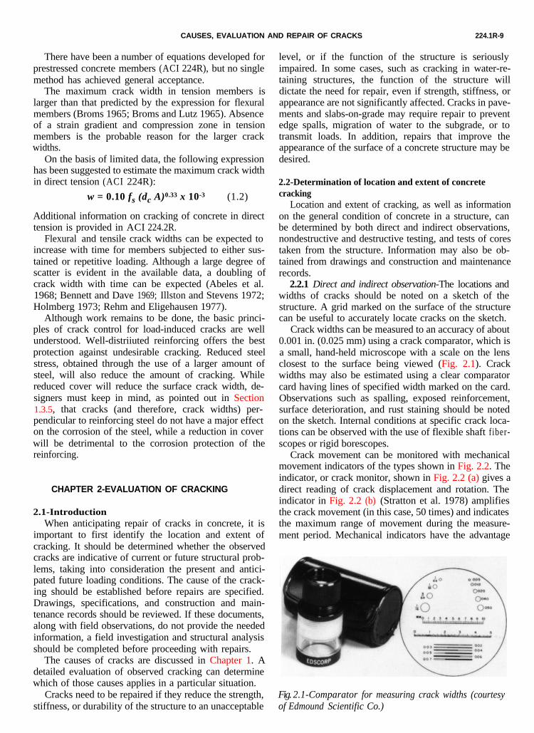
2.2.1 Direct and indirect observation-The locations andwidths of cracks should be noted on a sketch of thestructure. A grid marked on the surface of the structurecan be useful to accurately locate cracks on the sketch.
Crack widths can be measured to an accuracy of about0.001 in. (0.025 mm) using a crack comparator, which isa small, hand-held microscope with a scale on the lensclosest to the surface being viewed (Fig. 2.1). Crackwidths may also be estimated using a clear comparatorcard having lines of specified width marked on the card.Observations such as spalling, exposed reinforcement,surface deterioration, and rust staining should be notedon the sketch. Internal conditions at specific crack loca-tions can be observed with the use of flexible shaft fiber-scopes or rigid borescopes.
Crack movement can be monitored with mechanicalmovement indicators of the types shown in Fig. 2.2. Theindicator, or crack monitor, shown in Fig. 2.2 (a) gives adirect reading of crack displacement and rotation. Theindicator in Fig. 2.2 (b) (Stratton et al. 1978) amplifiesthe crack movement (in this case, 50 times) and indicatesthe maximum range of movement during the measure-ment period. Mechanical indicators have the advantage
Fig. 2.1-Comparator for measuring crack widths (courtesyof Edmound Scientific Co.)

224.1R-10 ACI COMMITTEE REPORT
Newly Mounted Monitor
Monitor After Crack Movement
(a)-Crack monitor (courtesy of Avongard)
CRACK ON GIRDER FACE
SEE ISOMETRIC SECTION AT
\
(b)-Crack movement indicator (Stratton et al. 1978)
Figure 2.2
CAUSES, EVALUATION AND REPAIR OF CRACKS 224.1R-11
that they do not require moisture protection. If moredetailed time histories are desired, a wide range oftransducers (most notably linear variable differentialtransformers or LVDT'S) and data acquisition systems(ranging from strip chart recorders to computer-basedsystems) are available.
Sketches can be supplemented by photographs docu-menting the condition of the structure at the time ofinvestigation. Guidance for making a condition survey ofconcrete in service is given in ACI 201.1R, ACI 201.3R,ACI 207.3R, ACI 345.1R, and ACI 546.1R.
2.2.2 Nondestructive testing-Nondestructive tests canbe made to determine the presence of internal cracksand voids and the depth of penetration of cracks visibleat the surface.
Tapping the surface with a hammer or using a chaindrag are simple techniques to identify laminar crackingnear the surface. A hollow sound indicates one or morecracks below and parallel to the surface.
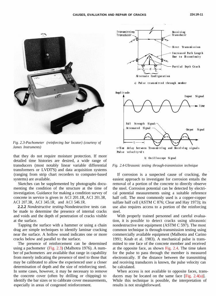
The presence of reinforcement can be determinedusing a pachometer (Fig. 2.3) (Malhotra 1976). A num-ber of pachometers are available that range in capabilityfrom merely indicating the presence of steel to those thatmay be calibrated to allow the experienced user a closerdetermination of depth and the size of reinforcing steel.In some cases, however, it may be necessary to removethe concrete cover (often by drilling or chipping) toidentify the bar sizes or to cahbrate cover measurements,especially in areas of congested reinforcement.
Fig. 2.3-Pachometer (reinforcing bar locator) (courtesy ofJames Instruments)
If corrosion is a suspected cause of cracking, the *easiest approach to investigate for corrosion entails theremoval of a portion of the concrete to directly observethe steel. Corrosion potential can be detected by electri-cal potential measurements using a suitable referencehalf cell. The most commonly used is a copper-coppersulfate half cell (ASTM C 876; Clear and Hay 1973); itsuse also requires access to a portion of the reinforcingsteel.
With properly trained personnel and careful evalua-tion, it is possible to detect cracks using ultrasonicnondestructive test equipment (ASTM C 597). The mostcommon technique is through-transmission testing usingcommercially available equipment (Malhotra and Carino1991; Knab et al. 1983). A mechanical pulse is trans-mitted to one face of the concrete member and receivedat the opposite face, as shown Fig. 2.4. The time takenfor the pulse to pass through the member is measuredelectronically. If the distance between the transmittingand receiving transducers is known, the pulse velocity canbe calculated.
When access is not available to opposite faces, trans-ducers may be located on the same face [Fig. 2.4(a)].While this technique is possible, the interpretation ofresults is not straightforward.
ReceivingTransducer
Direct Transmission
Increased Path LengthDue to Dlscontlnuity
Partial Depth Crack
Alternate Configuration
a) Pulse transmitted through member
AmplitudeLc. Input Signal
Full Strength SignalAttenuated Slgnal Output Signal
t=Time delay between Tronsmittlng and Recelvlng signalsPulse veloclty=d/t
b) Oscilloscope Signal
Fig. 2.4-Ultrasonic testing through-transmission technique

224.1R-12 ACI COMMITTEE REPORT
A significant change in measured pulse velocity canoccur if an internal discontinuity results in an increase inpath length for the signal. Generally, the higher the pulsevelocity, the higher the quality of the concrete. The inter-pretation of pulse velocity test results is significantlyimproved with the use of an oscilloscope that provides avisual representation of the received signal [Fig. 2.4(b)].
Some equipment provides only a digital readout of thepulse travel time, with no oscilloscope display. If no sig-nal arrives at the receiving transducer, a significant inter-nal discontinuity, such as a crack or void, is indicated. Anindication of the extent of the discontinuity can be ob-tained by taking readings at a series of positions on themember.
Ultrasonic equipment should be operated by a trainedperson, and the results should be evaluated cautiously byan experienced person, because moisture, reinforcingsteel, and embedded items may affect the results. Forexample, with fully saturated cracks, ultrasonic testingwill generally be ineffective. In some cases, it is difficultto discern between a group of close cracks and a singlelarge crack.
An alternative to through-transmission testing is thepulse-echo technique in which a simple transducer isused to send and receive ultrasonic waves. It has beendifficult to develop a practical pulse-echo test for con-crete. Pitch-catch systems have been developed which useseparate transmitting and receiving transducers (Alex-ander 1980). More detailed information on pulse-echoand other wave propagation methods is provided by Mal-hotra and Carino (1991).
Significant advances in use of wave propagationtechniques for flaw detection in concrete by the impact-echo technique have been made by Sansalone and Carino(1988, 1989). A mechanical pulse is generated by impact on one face of the member as illustrated in Fig. 2.5. The wave propagates through the member, reflects from a
1.0
4.=z 0.5a
0
Frequency (kHz)
(a )
1000 2000
82._E
EO
Time (PSI
. 0 100% (d)
.5
~
Jl0 I
0 50 100
Depth (%)
Fig. 2.5-Impact-echo response of a solid plate: a) schema-tic of test configuration; b) displacement waveform; c)amplitude spectrum; and d) normalized amplitude spectrum
defect or other surface of the member, and is received bya displacement transducer placed near the impact point.Fig. 2.5(b) shows a surface time-domain waveform re-ceived by the transducer. A resonance condition is set upin the member between the member boundaries or boun-dary and defect. By analyzing the frequency content ofthe time-domain waveform [Fig. 2.5(c)] the frequency
Radiography can also be used to detect internal dis-continuities. Both x-ray and gamma-ray equipment areavailable (Malhotra and Carino 1991; Bungey 1990). Theprocedures are best suited for detecting crack planesparallel to the direction of radiation; it is difficult todiscern crack planes perpendicular to the radiation.Gamma-ray equipment is less expensive and relativelyportable compared to x-ray equipment and therefore ap-pears to be more suitable for field testing.
An important use of nondestructive testing is findingthose portions of the structure that require a more de-tailed investigation, which may include core tests.
associated with the resonance appears as a peak ampli-tude. In the case of Fig. 2.5(a), the peak is that associ-ated with the thickness frequency [see Fig. 2.5(d)]. If aninternal flaw exists, then a significant amplitude peakfrom the reflections from the flaw depth will be observedat the associated flaw depth frequency.
2.2.3 Tests on concrete cores-Significant informationcan be obtained from cores taken from selected locationswithin the structure. Cores and core holes afford the op-portunity to accurately measure the width and depth ofcracks. In addition, an indication of concrete quality canbe obtained from compressive strength tests; however,cores that contain cracks should not be used to deter-mine concrete strength.
Petrographic examinations of cracked concrete canidentify material causes of cracking, such as alkalireactivities, cyclic freezing damage, "D" cracking, ex-pansive aggregate particles, fire-related damage, shrink-age, and corrosion. Petrography can also identify otherfactors that may be related to cracking such as the water-to-cement ratio, relative paste volume, and distributionof concrete components. Petrography can frequentlydetermine the relative age of cracks and can identifysecondary deposits on fracture surfaces, which have aninfluence on repair schemes.
Chemical tests for the presence of excessive chloridesindicate the potential for corrosion of embedded rein-forcement.
2.2.4 Review of drawings and construction data-Theoriginal structural design and reinforcement placing orother shop drawings should be reviewed to confirm thatthe concrete thickness and quality, along with installedreinforcing, meets or exceeds strength and serviceabilityrequirements noted in the governing building code(s). Adetailed review of actual applied loading compared todesign loads should getconfigurations, restraintconstruction and othercalculating the tensile
special consideration. Concreteconditions, and the presence ofjoints should be considered instresses induced by concrete
CAUSES, EVALUATION AND REPAIR OF CRACKS 224.1R-13
deformation (creep, shrinkage, temperature, etc.). Specialconsideration should be given to cracks that developparallel to one-way reinforced slabs primarily supportedon beams, but also bear on the girders that support thosebeams.
2.3-Selection of repair proceduresBased on the careful evaluation of the extent and
cause of cracking, procedures can be selected to accom-plish one or more of the following objectives:
1.2.3.4.5.6.7.
Restore and increase strength;Restore and increase stiffness;Improve functional performance;Provide watertightness;Improve appearance of the concrete surface;Improve durability; and/orPrevent development of corrosive environment at
reinforcement.Depending on the nature of the damage, one or more
repair methods may be selected For example, tensilestrength may be restored across a crack by injecting itwith epoxy or other high strength bonding agent. How-ever, it may be necessary to provide additional strengthby adding reinforcement or using post-tensioning. Epoxyinjection alone can be used to restore flexural stiffness iffurther cracking is not anticipated (ACI 503R).
Cracks causing leaks in water-retaining or otherstorage structures should be repaired unless the leakageis considered minor or there is an indication that thecrack is being sealed by autogenous healing (See section3.14). Repairs to stop leaks may be complicated by aneed to make the repatrs while the structures are inservice.
Cosmetic considerations may require the repair ofcracks in concrete. However, the crack locations maystill be visible and it is likely that some form of coatingover the entire surface may be required.
To minimize future deterioration due to the corrosionof reinforcement, cracks exposed to a moist or corrosiveenvironment should be sealed.
The key methods of crack repair available to accom-plish the objectives outlined are described in Chapter 3.
CHAPTER 3-METHODS OF CRACK REPAIR
3.1-IntroductionFollowing the evaluation of the cracked structure, a
suitable repair procedure can be selected. Successfulrepair procedures take into account the cause(s) of thecracking. For example, if the cracking was primarily dueto drying shrinkage, then it is likely that after a period oftime the cracks will stabilize. On the other hand, if thecracks are due to a continuing foundation settlement,repair will be of no use until the settlement problem iscorrected.
This chapter provides a survey of crack repairmethods, including a summary of the characteristics of
the cracks that may be repaired with each procedure, thetypes of structures that have been repaired, and a sum-mary of the procedures that are used. Readers are alsodirected to ACI 546.1R and ACI Compilation No. 5(1980), which specifically address the subject of concreterepair.
3.2-Epoxy injectionCracks as narrow as 0.002 in. (0.05 mm) can be
bonded by the injection of epoxy. The technique general-ly consists of establishing entry and venting ports at closeintervals along the cracks, sealing the crack on exposedsurfaces, and injecting the epoxy under pressure.
Epoxy injection has been successfully used in therepair of cracks in buildings, bridges, dams, and othertypes of concrete structures (ACI 503R). However, unlessthe cause of the cracking has been corrected, it will prob-ably recur near the original crack. If the cause of thecracks cannot be removed, then two options are avail-able. One is to rout and seal the crack, thus treating it asa joint, or, establish a joint that will accommodate themovement and then inject the crack with epoxy or othersuitable material. Epoxy materials used for structuralrepairs should conform to ASTM C 881 (Type IV). ACI504R describes practices for sealing joints, including jointdesign, available materials, and methods of application.
With the exception of certain moisture tolerantepoxies, this technique is not applicable if the cracks areactively leaking and cannot be dried out. Wet cracks canbe injected using moisture tolerant materials, but con-taminants in the cracks (including silt and water) canreduce the effectiveness of the epoxy to structurallyrepair the cracks.
The use of a low-modulus, flexible adhesive in a crackwill not allow significant movement of the concrete struc-ture. The effective modulus of elasticity of a flexiileadhesive in a crack is substantially the same as that of arigid adhesive (Adams et al. 1984) because of the thinlayer of material and high lateral restraint imposed bythe surrounding concrete.
Epoxy injection requires a high degree of skill forsatisfactory execution, and application of the techniquemay be limited by the ambient temperature. The generalprocedures involved in epoxy injection are as follows(ACI 503R):
Clean the cracks. The first step is to clean thecracks that have been contaminated., to the extentthis is possible and practical. Contaminants such asoil, grease, dirt, or fine particles of concrete preventepoxy penetration and bonding, and reduce the ef-fectiveness of repairs. Preferably, contaminationshould be removed by vacuuming or flushing withwater or other specially effective cleaning solutions.The solution is then flushed out using compressedair and a neutralizing agent or adequate time isprovided for air drying. It is important, however, torecognize the practical limitations of accomplishing
224.1R-14 ACI COMMITTEE REPORT
complete crack cleaning. A reasonable evaluationshould be made of the extent, and necessity, ofcleaning. Trial cleaning may be required.
l Seal the surfaces. Surface cracks should be sealedto keep the epoxy from leaking out before it hasgelled. Where the crack face cannot be reached, butwhere there is backfill, or where a slab-on-grade isbeing repaired, the backfill material or subbasematerial is sometimes an adequate seal; however,such a condition can rarely be determined in ad-vance, and uncontrolled injection can cause damagesuch as plugging a drainage system. Extreme cau-tion must therefore be exercised when injectingcracks that are not visible on all surfaces. A surfacecan be sealed by applying an epoxy, polyester, orother appropriate sealing material to the surface ofthe crack and allowing it to harden. If a permanentglossy appearance along the crack is objectionableand if high injection pressure is not required, astrippable plastic surface sealer may be appliedalong the face of the crack. When the job is com-pleted, the surface sealer can be stripped away toexpose the gloss-free surface. Cementitious sealscan also be used where appearance of the complet-ed work is important. If extremely high injectionpressures are needed, the crack can be cut out to adepth of 1/2 in. (13 mm) and width of about 3/4 in.(20 mm) in a V-shape, filled with an epoxy, andstruck off flush with the surface.
l Install the entry and venting ports. Three methodsare in general use:a. Fittings inserted into drilled holes. This method
was the first to be used, and is often used in con-junction with V-grooving of the cracks. Themethod entails drilling a hole into the crack, ap-proximately 3/4 in. (20 mm) in diameter and 1/2 to1 in. (13 to 25 mm) below the apex of the V-grooved section, into which a fitting such as apipe nipple or tire valve stem is usually bondedwith an epoxy adhesive. A vacuum chuck and bit,or a watercooled corebit, is useful in preventingthe cracks from being plugged with drilling dust.
b. Bonded flush fitting. When the cracks are not V-grooved, a method frequently used to provide anentry port is to bond a fitting flush with the con-crete face over the crack. The flush fitting has anopening at the top for the adhesive to enter anda flange at the bottom that is bonded to the con-crete.
c. Interruption in seal. Another system of providingentry is to omit the seal from a portion of thecrack. This method can be used when special gas-ket devices are available that cover the unsealedportion of the crack and allow injection of theadhesive directly into the crack without leaking.
l Mix the epoxy. This is done either by batch or con-tinuous methods. In batch mixing, the adhesivecomponents are premixed according to the manu-
facturer’s instructions, usually with the use of amechanical stirrer, like a paint mixing paddle. Caremust be taken to mix only the amount of adhesivethat can be used prior to commencement of gellingof the material. When the adhesive material beginsto gel, its flow characteristics begin to change, andpressure injection becomes more and more difficult.In the continuous mixing system, the two liquid ad-hesive components pass through metering and driv-ing pumps prior to passing through an automaticmixing head. The continuous mixing system allowsthe use of fast setting adhesives that have a shortworking life.
l Inject the epoxy. Hydraulic pumps, paint pressurepots, or air-actuated caulking guns may be used.The pressure used for injection must be selectedcarefully. Increased pressure often does little toaccelerate the rate of injection. In fact, the use ofexcessive pressure can propagate the existing cracks,causing additional damage.
If the crack is vertical or inclined, the injectionprocess should begin by pumping epoxy into the en-try port at the lowest elevation until the epoxy levelreaches the entry port above. The lower injectionport is then capped, and the process is repeated un-til the crack has been completely filled and all portshave been capped.
For horizontal cracks, the injection should pro-ceed from one end of the crack to the other in thesame manner. The crack is full if the pressure canbe maintained. If the pressure can not be main-tained, the epoxy is still flowing into unfilled por-tions or leaking out of the crack.
l Remove the surface seal. After the injected epoxyhas cured, the surface seal should be removed bygrinding or other means as appropriate.
l Alternative procedure. For massive structures, analternate procedure consists of drilling a series ofholes [usually 7/8 to 4-in. (20 to 100-mm) diameter]that intercepts the crack at a number of locations.Typically, holes are spaced at 5-ft (1.5-m) intervals.
Another method recently being used is a vacuum orvacuum assist method. There are two techniques: one isto entirely enclose the cracked member with a bag andintroduce the liquid adhesive at the bottom and to applya vacuum at the top. The other technique is to inject thecracks from one side and pull a vacuum from the other.Typically, epoxies are used; however, acrylics and poly-esters have proven successful.
Stratton and McCollum (1974) describe the use ofepoxy injection as an effective intermediate-term repairprocedure for delaminated bridge decks. As reported byStratton and McCollum the first, second, and sixth stepsare omitted and the process is terminated at a specificlocation when epoxy exits from the crack at some dis-tance from the injection ports. This procedure does notarrest ongoing corrosion. The procedure can also be

CAUSES, EVALUATION AND REPAIR OF CRACKS 224.1R-15
attempted for other applications, and is available as anoption, although not accepted universally. Success of therepair depends on the absence of bond-inhibiting con-taminants from the crack plane. Epoxy resins and injec-tion procedures should be carefully selected when at-tempting to inject delaminations. Unless there is suffi-cient depth or anchorage to surrounding concrete theinjection process can be unsuccessful or increase theextent of delamination. Smith (1992) provides informa-tion on bridge decks observed for up to seven years afterinjection. Smithson and Whiting describe epoxy injectionas a method to rebond delaminated bridge deck overlays.Committee 224 is developing additional information onthis application for inclusion in a future revision of thisReport.
3.3-Routing and sealingRouting and sealing of cracks can be used in condi-
tions requiring remedial repair and where structural re-pair is not necessary. This method involves enlarging thecrack along its exposed face and filling and sealing it witha suitable joint sealant (Fig. 3.1). This is a common tech-nique for crack treatment and is relatively simple in com-parison to the procedures and the training required forepoxy injection. The procedure is most applicable to ap-proximately flat horizontal surfaces such as floors andpavements. However, routing and sealing can be accom-plished on vertical surfaces (with a non-sag sealant) aswell as on curved surfaces (pipes, piles and pole).
Routing and sealing is used to treat both fiie patterncracks and larger, isolated cracks. A common and effec-tive use is for waterproofing by sealing cracks on the con-crete surface where water stands, or where hydrostaticpressure is applied. This treatment reduces the ability ofmoisture to reach the reinforcing steel or pass throughthe concrete, causing surface stains or other problems.
The sealants may be any of several materials, includingepoxies, urethanes, silicones, polysulfides, asphalticmaterials, or polymer mortars. Cement grouts should beavoided due to the likelihood of cracking. For floors, thesealant should be sufficiently rigid to support the antici-pated traffic. Satisfactory sealants should be able towithstand cyclic deformations and should not be brittle.
The procedure consists of preparing a groove at thesurface ranging in depth, typically, from 1/4 to 1 in. (6 to25 mm). A concrete saw, hand tools or pneumatic toolsmay be used. The groove is then cleaned by air blasting,sandblasting, or waterblasting, and dried. A sealant isplaced into the dry groove and allowed to cure.
A bond breaker may be provided at the bottom of thegroove to allow the sealant to change shape, without aconcentration of stress on the bottom (Fig. 3.2). Thebond breaker may be a polyethylene strip or tape whichwill not bond to the sealant.
Careful attention should be applied when detailing thejoint so that its width to depth aspect ratio will accom-modate anticipated movement (ACI 504R).
In some cases overbanding (strip coating) is used in-
Groove cut wlth sawor chipping tools7
a) Original Crack b) Routing c) Sealing
Fig. 3.1-Repair of crack by muting and sealing (Johnson1965)
Crock Closed No Bond Breaker
Fig. 3.2-Effect of bond breaker
With Bond Breaker
dependently of or in conjunction with routing and seal-ing. This method is used to enhance protection fromedge spalling and for aesthetic reasons to create a moreuniform appearing treatment. A typical procedure foroverbanding is to prepare an area approximately 1 to 3in. (25 to 75 mm) on each side of the crack by sandblast-
Note variable length, location andorientation of staples so that tensionacross crack is distributed in theconcrete rather than concentratedon a single plane.
Holes drilled in concreteto receive staples. Fillholes with nonshrink
Fig. 3.3-Repair of crack by stitching (Johnson 1965)
224.1R-16 ACI COMMITTEE REPORT
F
ing or other means of surface preparation, and apply acoating (such as urethane) 0.04 to 0.08 in. (1 to 2 mm)thick in a band over the crack. Before overbanding innon-traffic areas a bond breaker is sometimes used overa crack that has not been routed, or over a crack pre-viously routed and sealed. In traffic areas a bond breakeris not recommended. Cracks subject to minimal move-ment may be overbanded, but if significant movementcan take place, routing and sealing must be used inconjunction with overbanding to ensure a waterproofrepair.
3.4-StichingStitching involves drilling holes on both sides of the
crack and grouting in U-shaped metal units with shortlegs (staples or stitching dogs) that span the crack asshown in Fig 3.3 (Johnson 1965). Stitching may be usedwhen tensile strength must be reestablished across majorcracks (Hoskins 1991). Stitching a crack tends to stiffenthe structure, and the stiffening may increase the overallstructural restraint, causing the concrete to crack else!-where. Therefore, it may be necessary to strengthen theadjacent section or sections using technically corrected-reinforcing methods. Because stresses are often concen-trated, using this method in conjunction with othermethods may be necessary.
The stitching procedure consists of drilling holes onboth sides of the crack, cleaning the holes, and anchoringthe legs of the staples in the holes, with either a non-shrink grout or an epoxy resin-based bonding system. Thestaples should be variable in length, orientation, or both,and they should be located so that the tension trans-mitted across the crack is not applied to a single planewithin the section but is spread over an area.
3.5-Additional reinforcement3.5.1 Conventional reinforcement-Cracked reinforced
concrete bridge girders have been successfully repairedby inserting reinforcing bars and bonding them in placewith epoxy (Stratton et al. 1978, 1982; Stratton 1980).
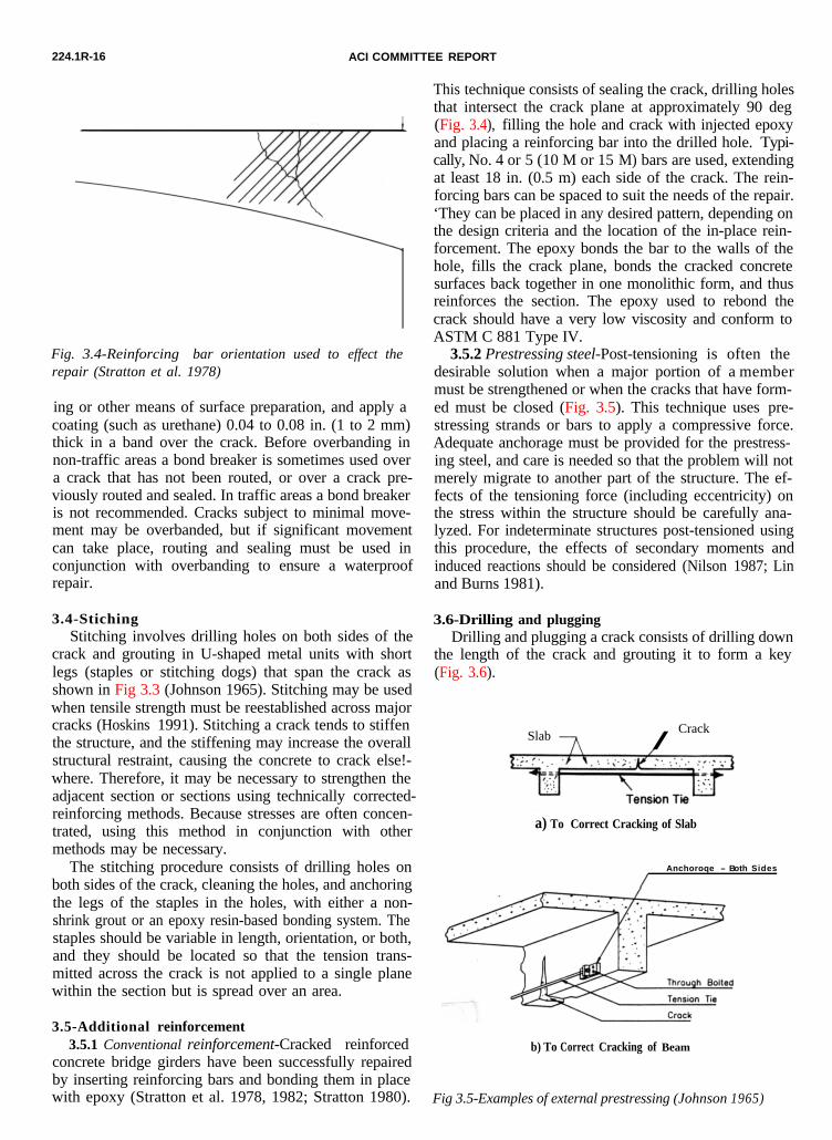
This technique consists of sealing the crack, drilling holesthat intersect the crack plane at approximately 90 deg(Fig. 3.4), filling the hole and crack with injected epoxyand placing a reinforcing bar into the drilled hole. Typi-cally, No. 4 or 5 (10 M or 15 M) bars are used, extendingat least 18 in. (0.5 m) each side of the crack. The rein-forcing bars can be spaced to suit the needs of the repair.‘They can be placed in any desired pattern, depending onthe design criteria and the location of the in-place rein-forcement. The epoxy bonds the bar to the walls of thehole, fills the crack plane, bonds the cracked concretesurfaces back together in one monolithic form, and thusreinforces the section. The epoxy used to rebond thecrack should have a very low viscosity and conform toASTM C 881 Type IV.
ig. 3.4-Reinforcing bar orientation used to effect therepair (Stratton et al. 1978)
3.5.2 Prestressing steel-Post-tensioning is often thedesirable solution when a major portion of a membermust be strengthened or when the cracks that have form-ed must be closed (Fig. 3.5). This technique uses pre-stressing strands or bars to apply a compressive force.Adequate anchorage must be provided for the prestress-ing steel, and care is needed so that the problem will notmerely migrate to another part of the structure. The ef-fects of the tensioning force (including eccentricity) onthe stress within the structure should be carefully ana-lyzed. For indeterminate structures post-tensioned usingthis procedure, the effects of secondary moments andinduced reactions should be considered (Nilson 1987; Linand Burns 1981).
Slab Crackn /
a) To Correct Cracking of Slab
Anchoroqe - Both Sides
/
b) To Correct Cracking of Beam
Fig 3.5-Examples of external prestressing (Johnson 1965)
3.6-Drilling and pluggingDrilling and plugging a crack consists of drilling down
the length of the crack and grouting it to form a key(Fig. 3.6).

CAUSES, EVALUATION AND REPAIR OF CRACKS 224.1R-17
Form key with precast concrete or mortor plugsset In bitumen. The bitumen Is to breok the bond
between plugs and hole so that plugs will not becrocked bv subsequent movement of the opening.If a particularly good seal Is required, drill a
plug with bitumen alone, usingSa key ond the second as a seal.
illed In stem of wall. C e n t e r e d
following down c r o c k . Size o f
ho le depends on width of crock. Use
2 ’ t o 2-1/2" minimum diameter.
Fig. 3.6-Repair of crack by drilling and plugging
This technique is only applicable when cracks run inreasonable straight lines and are accessible at one end.This method is most often used to repair vertical cracksin retaining walls.
A hole [typically 2 to 3 in. (50 to 75 mm) in diameter]should be drilled, centered on and following the crack.The hole must be large enough to intersect the crackalong its full length and provide enough repair materialto structurally take the loads exerted on the key. Thedrilled hole should then be cleaned, made tight, andfilled with grout. The grout key prevents transversemovements of the sections of concrete adjacent to thecrack. The key will also reduce heavy leakage through thecrack and loss of soil from behind a leaking wall.
If water-tightness is essential and structural loadtransfer is not, the drilled hole should be filled with aresilient material of low modulus in lieu of grout. If thekeying effect is essential, the resilient material can beplaced in a second hole, the fiit being grouted.
3.7-Gravity FillingLow viscosity monomers and resins can be used to seal
cracks with surface widths of 0.001 to 0.08 in. (0.03 to 2mm) by gravity filling (Rodler, et al. 1989). High-mole-cular-weight methacrylates, urethanes, and some low vis-cosity epoxies have been used successfully. The lower theviscosity, the finer the cracks that can be filled.
The typical procedure is to clean the surface by airblasting and/or waterblasting. Wet surfaces should bepermitted to dry several days to obtain the best crackfilling. The monomer or resin can be poured onto thesurface and spread with brooms, rollers, or squeegees.he material should be worked back and forth over thecracks to obtain maximum filling since the monomer orresin recedes slowly into the cracks. Excess materialshould be broomed off the surface to prevent slick,shining areas after curing. If surface friction is important,sand should be broadcast over the surface before themonomer or resin cures.
If the cracks contain significant amounts of silt,
moisture or other contaminants, the sealant cannot fillthem. Water blasting followed by a drying time may beeffective in cleaning and preparing these cracks.
Cores taken at cracks can be used to evaluate theeffectiveness of the crack filling. The depth of pene-tration of the sealant can be measured. Shear (or ten-sion) tests can be performed with the load applied in adirection parallel to the repaired cracks (as long asreinforcing steel is not present in the core in or near thefailure area). For some polymers the failure crack willoccur outside the repaired crack.
3.8-Grouting3.8.1 Portland cement grouting-Wide cracks, particu-
larly in gravity dams and thick concrete walls, may berepaired by filling with portland cement grout. Thismethod is effective in stopping water leaks, but it will notstructurally bond cracked sections. The procedure con-sists of cleaning the concrete along the crack; installingbuilt-up seats (grout nipples) at intervals astride the crack(to provide a pressure tight connection with the injectionapparatus); sealing the crack between the seats with a ce-ment paint, sealant, or grout; flushing the crack to cleanit and test the seal; and then grouting the whole area.Grout mixtures may contain cement and water or cementplus sand and water, depending on the width of thecrack. However, the water-cement ratio should be keptas low as practical to maximize the strength and mini-mize shrinkage. Water reducers or other admixtures maybe used to improve the properties of the grout. For smallvolumes, a manual injection gun may be used; for largervolumes, a pump should be used. After the crack is filled,the pressure should be maintained for several minutes toinsure good penetration.
3.8.2 Chemical grouting-Chemical grouts consist ofsolutions of two or more chemicals (such as urethanes,sodium silicates, and acrylomides) that combine to forma gel, a solid precipitate, or a foam, as opposed tocement grouts that consist of suspensions of solid par-ticles in a fluid. Cracks in concrete as narrow as 0.002 in.(0.05 mm) have been filled with chemical grout.
The advantages of chemical grouts include applicabili-ty in moist environments (excess moisture available),wide limits of control of gel time, and their ability to beapplied in very fine fractures. Disadvantages are the highdegree of skill needed for satisfactory use and their lackof strength.
3.9-DrypackingDrypacking is the hand placement of a low water con-
tent mortar followed by tamping or ramming of the mor-tar into place, producing intimate contact between themortar and the existing concrete (U.S. Bureau of Rec-lamation 1978). Because of the low water-cement ratio ofthe material, there is little shrinkage, and the patchremains tight and can have good quality with respect todurability, strength, and watertightness.
Drypack can be used for filling narrow slots cut for the

224.1R-18 ACI COMMITTEE REPORT
Semicircular pipe (8” diam.),flanged as shown
concentrically overpipe at least 2 daysprior to placementof lift.
Holes drilled in concretefor pegs inserted to holdpipe in place.
Fig. 3.7-Crack arrest method of crack repair
repair of dormant cracks. The use of drypack is not ad-visable for filling or repairing active cracks.
Before a crack is repaired by drypacking, the portionadjacent to the surface should be widened to a slot about1 in. (25 mm) wide and 1 in. (25 mm) deep. The slotshould be undercut so that the base width is slightlygreater than the surface width.
After the slot is thoroughly cleaned and dried, a bondcoat, consisting of cement slurry or equal quantities ofcement and fine sand mixed with water to a fluid pasteconsistency, or an appropriate latex bonding compound(ASTM C 1059), should be applied. Placing of the drypack mortar should begin immediately. The mortar con-sists of one part cement, one to three parts sandpassinga No. 16 (1.18 mm) sieve, and just enough water so thatthe mortar will stick together when molded into a ball byhand.
If the patch must match the color of the surroundingconcrete, a blend of grey portland cement and whiteportland cement may be used. Normally, about one-thirdwhite cement is adequate, but the precise proportionscan be determined only by trial.
To minimize shrinkage in place, the mortar shouldstand for 1/2 hour after mixing and then should be re-mixed prior to use. The mortar should be placed in layersabout 3/8 in. (10 mm) thick. Each layer should be thor-oughly compacted over the surface using a blunt stick orhammer, and each underlying layer should be scratchedto facilitate bonding with the next layer. There need beno time delays between layers.
The mortar may be finished by laying the flat side ofa hardwood piece against it and striking it several timeswith a hammer. Surface appearance may be improved bya few light strokes with a rag or sponge float. The repairshould be cured by using either water or a curing com-pound. The simplest method of moist curing is to supporta strip of folded wet burlap along the length of the crack.
3.10-Crack arrestDuring construction of massive concrete structures,
cracks due to surface cooling or other causes may devel-op and propagate into new concrete as construction pro-gresses. Such cracks may be arrested by blocking thecrack and spreading the tensile stress over a larger area(U.S. Army Corps of Engineers 1945).
A piece of bond-breaking membrane or a grid of steel
mat may be placed over the crack as concreting contin-ues. A semicircular pipe placed over the crack may alsobe used (Fig. 3.7). A description of installation proce-dures for semicircular pipes used during the constructionof a massive concrete structure follows: (1) The semi-circular pipe is made by splitting an 8-in. (200-mm), 16-gage pipe and bending it to a semicircular section withabout a 3-in. (75-mm) flange on each side; (2) the areain the vicinity of the crack is cleaned; (3) the pipe isplaced in sections so as to remain centered on the crack;(4) the sections are then welded together; (5) holes arecut in the top of the pipe to receive grout pipes; and (6)after setting the grout pipes, the installation is coveredwith concrete placed concentrically over the pipe byhand. The installed grout pipes are used for grouting thecrack at a later date, thereby restoring all or a portion ofthe structural continuity.
3.11-Polymer impregnationMonomer systems can be used for effective repair of
some cracks. A monomer system is a liquid consisting ofmonomers which will polymerize into a solid. Suitablemonomers have varying degrees of volatility, toxicity andflammability, and they do not mix with water. They arevery low in viscosity and will soak into dry concrete,filling the cracks, much as water does. The most commonmonomer used for this purpose is methyl methacrylate.
Monomer systems used for impregnation contain acatalyst or initiator plus the basic monomer (or combin-ation of monomers). They may also contain a cross-linking agent. When heated, the monomers join together,or polymerize, creating a tough, strong, durable plasticthat greatly enhances a number of concrete properties.
If a cracked concrete surface is dried, flooded with themonomer, and polymerized in place, some of the crackswill be filled and structurally repaired. However, if thecracks contain moisture, the monomer will not soak intothe concrete at each crack face, and consequently, the re-pair will be unsatisfactory. If a volatile monomer evapor-ates before polymerization, it will be ineffective. Polymerimpregnation has not been used successfully to repairfme cracks. Polymer impregnation has primarily beenused to provide more durable, impermeable surfaces(Webster et al. 1978; Hallin 1978).
Badly fractured beams have been repaired using poly-mer impregnation. The procedure consists of drying thefracture, temporarily encasing it in a watertight (mono-mer proof) band of sheet metal, soaking the fractureswith monomer, and polymerizing the monomer. Largevoids or broken areas in compression zones can be filledwith fine and coarse aggregate before being flooded withmonomer, providing a polymer concrete repair. A moredetailed discussion of polymers is given in AC1 548R.
3.12-Overlay and surface treatmentsFine surface cracks in structural slabs and pavements
may be repaired using either a bonded overlay or surfacetreatment if there will not be further significant move-
CAUSES, EVALUATION AND REPAIR OF CRACKS 224.1R-19
ment across the cracks. Unbonded overlays may be usedto cover, but not necessarily repair a slab. Overlays andsurface treatments can be appropriate for cracks causedby one-time occurrences and which do not completelypenetrate the slab. These techniques are not appropriatefor repair of progressive cracking, such as that induced byreactive aggregates, and D-cracking.
Slabs-on-grade in freezing climates should not berepaired by an overlay or surface treatment that is avapor barrier. An impervious barrier will cause condensa-tion of moisture passing from the subgrade, leading tocritical saturation of the concrete and rapid disintegrationduring cycles of freezing and thawing.
3.12.1 Surface treatments-Low solids and and low-viscosityresin-based systems have been used to seal the concretesurfaces, including treatment of very fine cracks. They aremost suited for surfaces not subject to significant wear.
Bridge decks and parking structure slabs, as well asother interior slabs may be coated effectively after cracksare treated by injecting with epoxy or by routing andsealing. Materials such as urethanes, epoxies, polyesters,and acrylics have been applied in thickness of 0.04 to 2.0in. (1 to 50 mm), depending on the material and purposeof the treatment. Skid-resistant aggregates are oftenmixed into the material or broadcast onto the surface toimprove traction.
3.12.2 Overlays-Slabs containing find dormant crackscan be repaired by applying an overlay, such as polymer-modified portland cement mortar or concrete, or by silicafume concrete. Slabs with working cracks can be overlaidif joints are placed in the overlay directly over the work-ing cracks. In highway bridge applications, an overlaythickness as low as 1-1/4 in. (30 mm) has been used suc-cessfully (NCHRP Synthesis 57). Suitable polymers in-clude styrene butadiene or acrylic latexes. The resinsolids should be at least 15 percent by weight of theportland cement, with 20 percent usually being optimum(Clear and CholIar 1978).
The surface to be overlaid should be cleaned toremove laitance, carbonated or otherwise weak material,or contaminants, such as grease or oil. A bond coat con-sisting of the mortar fraction broom-applied, or an epoxyadhesive should be applied immediately before placingthe overlay. Since polymer-modified concretes normallysolidify rapidly, continuous batching and mixing equip-ment should be used. Polymer-modified overlays shouldbe mixed, placed and finished rapidly (within 15 min inwarm weather). A 24-hr moist curing is typical for theseoverlays.
3.13-Autogenous healingA natural process of crack repair known as “auto-
genous healing” can occur in concrete in the presence ofmoisture and the absence of tensile stress (Lauer andSlate 1956). It has practical application for closingdormant cracks in a moist environment, such as may befound in mass concrete structures.
Healing occurs through the continued cement hydra-
tion and the carbonation of calcium hydroxide in thecement paste by carbon dioxide, which is present in thesurrounding air and water. Calcium carbonate and cal-cium hydroxide crystals precipitate, accumulate, and growwithin the cracks. The crystals interlace and twine,producing a mechanical bonding effect, which is supple-mented by a chemical bonding between adjacent crystalsand between the crystals and the surfaces of the pasteand the aggregate. As a result, some of the tensilestrength of the concrete is restored across the crackedsection, and the crack may become sealed.
Healing will not occur if the crack is active and issubjected to movement during the healing period. Heal-ing will also not occur if there is a positive flow of waterthrough the crack, which dissolves and washes away thelime deposit, unless the flow of water is so slow thatcomplete evaporation occurs at the exposed face causingredeposition of the dissolved salts.
Saturation of the crack and the adjacent concrete withwater during the healing process is essential for devel-oping any substantial strength. Submergence of thecracked section is desirable. Alternatively, water may beponded on the concrete surface so that the crack issaturated. The saturation must be continuous for theentire period of healing. A single cycle of drying andreimmersion will produce a drastic reduction in theamount of healing strength. Healing should be com-menced as soon as possible after the crack appears.Delayed healing results in less restoration of strengththan does immediate correction.
CHAPTER 4-SUMMARY
This report is intended to serve as a tool in theprocess of crack evaluation and repair of concrete struc-tures.
The causes of cracks in concrete are summarized alongwith the principal procedures used for crack control.Both plastic and hardened concrete are considered. Theimportance of design, detailing, construction procedures,concrete proportioning, and material properties are dis-cussed.
The techniques and methodology for crack evaluationare described Both analytical and field requirements arediscussed. The need to determine the causes of crackingas a necessary prerequisite to repair is emphasized. Theselection of successful repair techniques should considerthe causes of cracking, whether the cracks are active ordormant, and the need for repairs. Criteria for the selec-tion of crack repair procedures are based on the desiredoutcome of the repairs.
Twelve methods of crack repair are presented, in-cluding the techniques, advantages and disadvantages,and areas of application of each.
ACKNOWLEDGMENT
ACI Committee 224 - Cracking, gratefully acknow-

224.1R-20 ACI COMMITTEE REPORT
ledges the assistance of Robert Gaul, Paul Krauss, andJames Warner, non-members of the Committee, for theirsuggestions and review of the revisions to this document.The Committee would also like to recognize the contri-butions of Raymond J. Schutz, former Committee Mem-ber Paul H. Karr and deceased Committee MembersDonald L. Houghton and Robert E. Philleo who wereContributing Authors of the original version of ACI224.1R.
American Concrete Institute201.1R Guide for Making a Condition Survey of Con-
crete in Service201.2R207.1R207.2R
Guide to Durable ConcreteMass Concrete
207.4R
Effect of Restraint, Volume Change, and Rein-forcement on Cracking of Mass ConcreteCooling and Insulating Systems for Mass Con-crete
224R224.2R
Control of Cracking in Concrete StructuresCracking of Concrete Members in Direct Ten-sion
224.3R302.1R304R
305R308309R309.2R
318
343R
345R
Joints in Concrete ConstructionGuide to Concrete Floor and Slab ConstructionGuide for Measuring, Mixing Transporting andPlacing ConcreteHot Weather ConcretingStandard Practice for Curing ConcreteGuide for Consolidation of ConcreteIdentification and Control of Consolidation-Related Surface Defects in Formed ConcreteBuilding Code Requirements for ReinforcedConcreteAnalysis and Design of Reinforced ConcreteBridge StructuresGuide for Concrete Highway Bridge Deck Con-struction
347R350R
503R504R517.2R
546.1R
Guide to Concrete FormworkEnvironmental Engineering of Concrete Struc-turesUse of Epoxy Compounds with ConcreteGuide to Sealing Joints in Concrete StructuresAccelerated Curing of Concrete at AtmosphericPressure--State of the ArtGuide for Repair of Concrete Bridge Superstruc-tures
548R Polymers in Concrete
CHAPTER 5-REFERENCES
5.1 Recommended referencesThe Documents of the various standards-producing
organizations referred to in this document are listedbelow with their serial designation.
American Association of State Highway and TransportationOfficials
Standard Specification for Highway Bridges
American Society for Testing and MaterialsC 150C 595
C 597
C 876
C 881
C 1059
Standard Specification for Portland CementStandard Specification for Blended HydraulicCementsStandard Test Method for Pulse Velocity throughConcreteStandard Test Method for Half Cell Potentials ofReinforcing Steel in ConcreteStandard Specification for Epoxy-Resin-BaseBonding Systems for ConcreteStandard Specification for Latex Agents forBonding Fresh to Hardened Concrete
The above publications may be obtained from the follow-ing organizations:
American Association of State Highway and Transporta-tion Officials444 N Capitol Street NWSuite 224Washington, D.C. 20001
American Concrete InstituteP.O. Box 19150Detroit MI 48219
American Society for Testing and Materials1916 Race StreetPhiladelphia PA 19103
5.2-Cited referencesAbdun-Nur, Edward A. (1983), “Cracking of Concrete
- Who Cares?,” Concrete International: Design and Con-struction, V. 5, No. 7, July, pp. 27-30.
Abeles, Paul W.; Brown, Earl L., II, and Morrow, JoeW. (1968), “Development and Distribution of Cracks inRectangular Prestressed Beams During Static andFatigue Loading,” Journal, Prestressed Concrete Institute,V. 13, No. 5, Oct., pp. 36-51.
ACI Compilation No. 5 (1980), “Concrete Repair andRestoration,” American Concrete Institute, Detroit, 118pp. (compiled from Concrete International Design andConstruction, V. 2, No. 9, Sept.).
Adams, Robert D., and Wake, William C. (1984),Structural Adhesive Joints in Engineering, Elsevier AppliedScience Publishers, Ltd., Essex, England, pp. 121-125.
Alberta Ministry of Highways (1990), “Alberta TestProcedures for Evaluation of Concrete Sealer,” BTOO1, 5pp.
Alexander, A. Michel (1980), “Development of Proce-dures for Nondestructive Testing of Concrete Structures:Report 2, Feasibility of Sonic Pulse-Echo Technique,”Miscellaneous Paper No. C-77-11, U.S. Army EngineerWaterways Experiment Station, Vicksburg, 25 pp.
Beeby, A.W. (1983), “Cracking, Cover, and Corrosionof Reinforcement,” Concrete International Design andConstruction, V. 5, No. 2, Feb., pp. 35-40.
Bennett, E.W., and Dave, N.J. (1969), "Test Perfor-

CAUSES, EVALUATlON AND REPAIR OF CRACKS 224.1R-21
mances and Design of Beams with Limited Prestress,”The Structural Engineer (London), V. 47, No. 12, Dec.,pp. 487-496.
Broms, Bengt B. (1965), “Crack Width and Spacing inReinforced Concrete Members,” ACI JOURNAL, Proceed-ings, V. 62, No. 10, Oct., pp. 1237-1256.
Broms, Bengt B., and Lutz, LeRoy A. (1965), “Effectsof Arrangement of Reinforcement on Crack Width andSpacing of Reinforced Concrete Members,” ACIJOURNAL, Proceedings, V. 62, No. 11, NOV., pp. 1395-1410.
Bungey, J.H. (1990), Testing of Concrete in Structures,2nd ed., Chapman and Hall, NY.
Butt, Yu M.; Kolbasov, V.M.; and Timashev, V.V.(1969) “High Temperature Curing of Concrete UnderAtmospheric Pressure,” Proceedings, 5th InternationalSymposium on the Chemistry of Cement (Tokyo, 1968),Cement Association of Japan, pp.437-476.
CaIlan, Edwin J. (1952), “Thermal Expansion ofAggregates and Concrete Durability,” ACI JOURNAL,Proceedings, V. 48, No. 6, Feb., pp. 485-504.
Carlson, Roy W. (1938), “Drying Shrinkage of Con-crete as Affected by Many Factors,” Proceedings ASTM,V. 38, Part 2, pp. 419-437.
Carlson, Roy W.; Houghton, Donald L.; and Polivka,Milos (1979), “Causes and Control of Cracking in Un-reinforced Mass Concrete,” ACI JOURNAL, Proceedings,V. 76, No. 7, July, pp. 821-837.
Clear, Kenneth C., and ChoIlar, Brian H. (1978)“Styrene-Butadiene Latex Modifiers for Bridge DeckOverlay Concrete,“ Report No. FHWA-RD-78-35, FederalHighway Administration, Washington, D.C., 124 pp.
Clear, K.C., and Hay, R.E. (1973), “Time-to-Corrosionof Reinforcing Steel in Concrete Slabs. V. 1, Effects ofMix Design and Construction Parameters,” Report No.FHWA-RD-73-32, Federal Highway Administration,Washington, DC., 103 pp.
Concrete Institute of Australia (1972), Third ProgressReport of the Low Pressure Steam-Curing of Concrete,North Sydney, 26 pp.
Dakhil, Fadh H.; Cady, Philip D.; and Carrier, RogerE. (1975), “Cracking of Fresh Concrete as Related toReinforcement,” ACI JOURNAL, Proceedings, V. 72, No.8, Aug., pp. 421-428.
Dusinberre, D.M. (1945), “Numerical Methods forTransient Heat Flow,” Transactions, American Society ofMechanical Engineers, V. 67, Nov., pp. 703-712.
Gergely, Peter (1981), “Role of Cover and Bar Spacingin Reinforced Concrete,” Significant Developments inEngineering Practice and Research, SP-72, AmericanConcrete Institute, Detroit, pp. 133-147.
Gergely, Peter, and Lutz, LeRoy A. (1968), “MaximumCrack Width in Reinforced Concrete Members,” Causes,Mechanism, and Control of Cracking in Concrete, SP-20,American Concrete Institute, pp. 87-117.
Higginson, Elmo C. (1961), “Effect of Steam Curingon the Important Properties of Concrete,” ACI JOURNAL,Proceedings, V. 58, No. 3, Sept., pp. 281-298.
Hallin, J.P., “Field Evaluation of Polymer Impreg-nation of New Bridge Deck Surfaces,” Polymers in Con-crete, SP-58, American Concrete Institute, Detroit, 1978,pp. 267-280.
Hoffman, P.C.; McClure, R.M.; and West, H.H. (1983),“Temperature Study of an Experimental Segmental Con-crete Bridge,” Journal, Prestressed Concrete Institute, V.28, No. 2, Mar.-Apr., pp. 78-97.
Holmberg, Ake (1973), “Crack Width Prediction andMinimum Reinforcement for Crack ControI,” DanskSlesab for Bygningsstatitik (Copenhagen), V. 44, No. 2,June, pp. 41-50.
Hoskins, B.E.; Fowler, D.W.; and McCullough, B.F.(1991), “An Evaluation of Repair Techniques Used forUncontrolled Longitudinal Cracking and Failed Longi-tudinal Joints,” Research Report 920-4, Center forTransportation Research, The University of Texas atAustin, 21 pp.
Houghton, Donald L. (1972), “Concrete Strain Capa-city Tests - Their Economic Implications,” EconomicalConstruction of Concrete Dams, American Society of CivilEngineers, New York, pp. 75-99.
Houghton, Donald L. (1976), “Determining TensileStrain Capacity of Mass Concrete,” ACI JOURNAL, Pro-ceedings, V. 73, No. 12, Dec., pp. 691-700.
Illston, J.M. and Stevens, R.F. (1972), “Long-TermCracking in Reinforced Concrete Beams,” Proceedings,Institution of Civil Engineers (London), Part 2, V. 53, pp.445-459.
Jastrzebski, Zbigniew D. (1961), Nature and Propertiesof Engineering Materials, John Wiley and Sons, NewYork, 571 pp.
Johnson, Sydney M. (1965), Deterioration, Maintenanceand Repair of Structures, McGraw-Hill Book Co., NewYork, 373 pp.
Kaminetzky, Dov (1981), “FaiIures During and AfterConstruction,” Concrete Construction, V. 26, No. 8, Aug.,pp. 641-649.
KeIly, Joe W. (1981), “Cracks in Concrete: Part 1, Part2,” Concrete Construction, V. 26, No. 9, Sept., pp. 725-734.
Kirkbride, T. (1971a), “Review of Accelerated CuringProcedures,” Precast Concrete (London), V. 1, No. 2,Feb., pp. 87-90.
Kirkbride, T.W. (1971b), “Burner Curing,” Precast Con-crete (London), V. 1, No. 11, NOV., pp. 644-646.
Knab, L.I.; Blessing, G.V.; and Clifton, J.R. (1983),“Laboratory Evaluation of Ultrasonics for Crack Detec-tion in Concrete,” ACI JOURNAL, Proceedings, V. 80, No.1, Jan.-Feb., pp. 17-27.
Lauer, Kenneth R., and Slate, Floyd O. (1956), “Auto-genous Healing of Cement Paste,” ACI JOURNAL, Pro-ceedings, V. 27, No. 10, June, pp. 1083-1098.
Libby, James R. (1977), Modern Prestressed Concrete,2nd Edition, Van Nostrand Reinhold, New York, pp.388-390.
Lin, T.Y., and Bums, Ned H. (1981), Design of Pre-stressed Concrete Structures, 3rd edition, John Wiley &

224.1R-22 ACI COMMITTEE REPORT
ACI 224.1R-93 was submitted to letter ballot of the committee and processedin accordance with ACI standardization procedures.
Sons, New York, 646 pp.Malhotra, V.M. and Carino, NJ. (Editors) (1991),
Handbook on Nondestructive Testing of Concrete, CRCPress, Boca Raton, Fl. 343 p.
Mansfield, G.A. (1948), “Curing - A Problem inThermodynamics,” Rock Products, V. 51, NO. 8, Aug., p.212.
Mast, Robert F. (1981), “Roof Collapse at AntiochHigh School,” Journal, Prestressed Concrete Institute, V.26, No. 3, May-June, pp. 29-53.
NCHRP Synthesis of Highway Practice No. 57 (1979),“Durability of Concrete Bridge Decks,” TransportationResearch Board, Washington, D.C., May, 61 pp.
Nilson, Arthur H. (1987), Design of Prestressed Con-crete, 2nd Ed., John Wiley and Sons, New York, 526 pp.
Nurse, R.W. (1949), “Steam Curing of Concrete,” Mag-azine of Concrete Research (London), V. 1, No. 2, June,pp. 79-88.
PCI Committee on Quality Control Performance Cri-teria (1985), “Fabrication and Shipment Cracks in Precastor Prestressed Beams and Columns,” PCI Journal, May-June, pp. 24-49.
PCI Committee on Quality Control Performance Cri-teria (1983), “Fabrication and Shipment Cracks in Pre-stressed HoIlow-Core Slabs and Double Tees,” PCI Jour-nal, V. 28, No. 1, Jan.-Feb., pp. 18-39.
PCI Energy Committee (1981), Discussion of “Acceler-ated Curing of Concrete at Atmospheric Pres-sure - State of the Art,” ACI JOURNAL, Proceedings,Jul.-Aug., pp. 320-324.
Pickett, Gerald (1956), “Effect of Aggregate onShrinkage of Concrete,” ACI JOURNAL, Proceedings, V.52, No. 5, Jan., pp. 581-590.
Powers, T.C. (1975), “Freezing Effects in Concrete,”Durability of Concrete, SP-47, American Concrete Insti-tute, Detroit, pp. l-11.
Price, Walter H. (1982), “Control of Cracking DuringConstruction,” Concrete International: Design and Con-struction, V. 4, No. 1, Jan., pp. 40-43.
Priestly, M.J. Nigel (1978), “Design of ConcreteBridges for Temperature Gradients,”ACI Journal, Pro-ceedings, V. 75, No. 5, May, pp. 209-217.
Rehm, Gallus, and Eligehausen, Rolf (1977), “LappedSplices of Deformed Bars Under Repeated Loadings(Ubergreifungstosse von Rippenstahlen unter nichtruhender Belastung),” Beton und Stahlbeton (Berlin), No.7, pp. 170-174.
Rodler, D.J.; D.P. Whitney; D.W. Fowler; and D.L.Wheat, “Repair of Cracked Concrete with High Mole-cular Weight Methacrylates,” Polymers in Concrete:Advances and Applications, SP-116, American ConcreteInstitute, Detroit, 1989, pp. 113-127.
Sansalone, M. and Carino, N.J. (1988), “Laboratoryand Field Studies of the Impact-Echo Method for FlawDetection of Concrete,” SP-112, American ConcreteInstitute, Detroit, pp. l-20.
Sansalone, M. and Carino, N.J. (1989), “DetectingDelaminations in Concrete Slabs with and without Over-
lays Using the Impact-Echo Method,” ACI MaterialsJournal, V. 86, No. 2, Mar-Apr., pp. 175-184.
Shideler, Joseph J., and Toennies, Henry T. (1963),“Plant Drying and Carbonat ion of ConcreteBlock - NCMA-PCA Cooperative Program,” ACIJOURNAL, Proceedings, V. 60, No. 5, May 1963, pp. 617-634. Also, Development Department Bulletin No. D64,Portland Cement Association.
Smith, Barbara J. (1992), “Epoxy Injection of BridgeDeck Delaminations," Transportation Research Record1533, Transportation Research Board, National ResearchCouncil, pp. 10-18.
Smithson, Leland D., and Whiting, John E. (1992),“Rebonding Delaminated Bridge Deck Overlays,” Con-crete Repair Digest, V. 3, No. 3, June/July, pp. 100-101.
Snowdon, L.C., and Edwards, A.G. (1962), "The Mois-ture Movement of Natural Aggregate and Its Effect onConcrete,” Magazine of Concrete Research (London), V.14, No. 41, July, pp. 109-116.
Stratton, F. Wayne (1980), “Custom Concrete DrillHelps Repair Shear Cracks in Bridge Girders,” ConcreteInternational: Design and Construction, V. 2, No. 9, Sept.,pp. 118-119.
Stratton, F. Wayne, and McCollom, Bruce F. (1974),“Repair of Hollow or Softened Areas in Bridge Decks byRebonding with Injected Epoxy Resin or Other Poly-mers,” Report No. K-F-72-5, State Highway Commissionof Kansas, July, 104 pp.
Stratton, F. Wayne; Alexander, Roger; and Nolting,William (1978), “Cracked Structural Concrete Repairthrough Epoxy Injection and Rebar Insertion,” ReportNo. FHWA-KS-RD.78-3, Kansas Department of Trans-portation, Topeka, Nov., 56 pp.
U.S. Army Corps of Engineers (1945), “ConcreteOperation with Relation to Cracking at Norfolk Dam,”Little Rock District, Arkansas, Oct.
U.S. Bureau of Reclamation (1975), Concrete Manual,8th edition, Denver, 627 pp.
Verbeck, George G. (1958), “Carbonation of HydratedPortland Cement,” Cement and Concrete, STP-205, Amer-ican Society for Testing and Materials, Philadelphia, pp.17-36. Also, Research Department Bulletin NO. 87,Portland Cement Association.
Verbeck, George G. (1975), “Mechanisms of Corrosionof Steel in Concrete,” Corrosion of Metals in Concrete,SP-49, American Concrete Institute, Detroit, pp. 21-38.
Webster, R.P.; Fowler, D.W.; and Paul D.R. (1978),“Bridge Deck Impregnation in Texas,” Polymers in Con-crete, SP-58, American Concrete Institute, Detroit, pp.249-265.
Wimsatt, A.W.; McCullough, B.F.; and Bums, N.H(1987) “Methods of Analyzing and Factors InfluencingFrictional Effects of Subbases,” Research Report 459-2F,Center for Transportation Research, The University ofTexas at Austin, November, 77 pp.