220 cnc machines
DESCRIPTION
cncTRANSCRIPT

CNC MACHINES (CH7)
PROCCESSING EQUIPMENT
MILLING MACHINES

MCU

INDEXER FIXTURES - VICE

CHIP CONVEYOR PART FEEDER
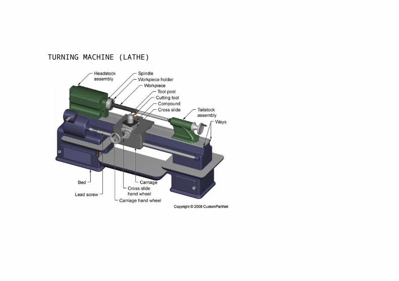
TURNING MACHINE (LATHE)

COORDINATES SYSTEM
MILLING COORDINATE SYSTEM
Flat and prismatic workpiece
a. Cartesian coordinates system (X-Y-Z) right hand ruleb. Rotational axis (a,b,c), right hand rule
a. Orient the workpiece to preset different surface for machiningb. Orientation of tool or workhead at some angle relative to the part.

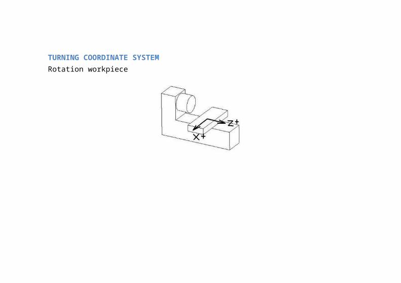
TURNING COORDINATE SYSTEMRotation workpiece

MOTION CONTROL SYSTEM1. Point to Point2. Continuous Path Control
POINT TO POINTPositioning system, move the worktable to a programmed location without regards for the path taken to get that location.
Once move has been completed, some processing action is accomplished by the workhead,
Example: Drilling.
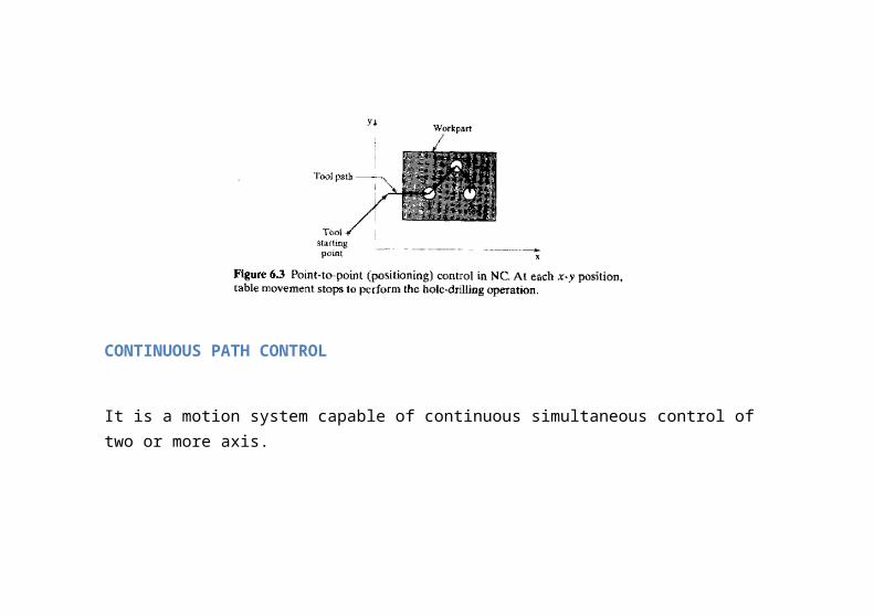
CONTINUOUS PATH CONTROL
It is a motion system capable of continuous simultaneous control of two or more axis.
In this case the tool perform the process while the worktable is moving,

Example
Milling, turning

INTERPOLATION METHOD
Path
1. Linear interpolation2. Circular interpolation3. Helical interpolation4. Parabolic and cubic interpolation

Linear interpolationIt is the most basic method
Circular interpolationThe method permits programming a circular arc by specifying the following parameter:

Coordinate of starting point Coordinate of end point Center or radius Direction of path
Helical interpolation
This method combines circular interpolation scheme for two axis with linear interpolation of a third axis.
Parabolic and cubic interpolation
This method provides approximation of free form curves using higher order ecuation
It is not common method.

MACHINE CONTROL UNIT
FUNCTIONS OF COMPUTER NUMERICAL CONTROL
1. Storage of more than one part program2. Various form of program input3. Program editing at the machine tool4. Fixed cycles and programming subroutines5. Interpolation6. Positioning features to setup7. Cutter length and size compensation8. Acceleration and deceleration calculation9. Communication interface10. Diagnostics

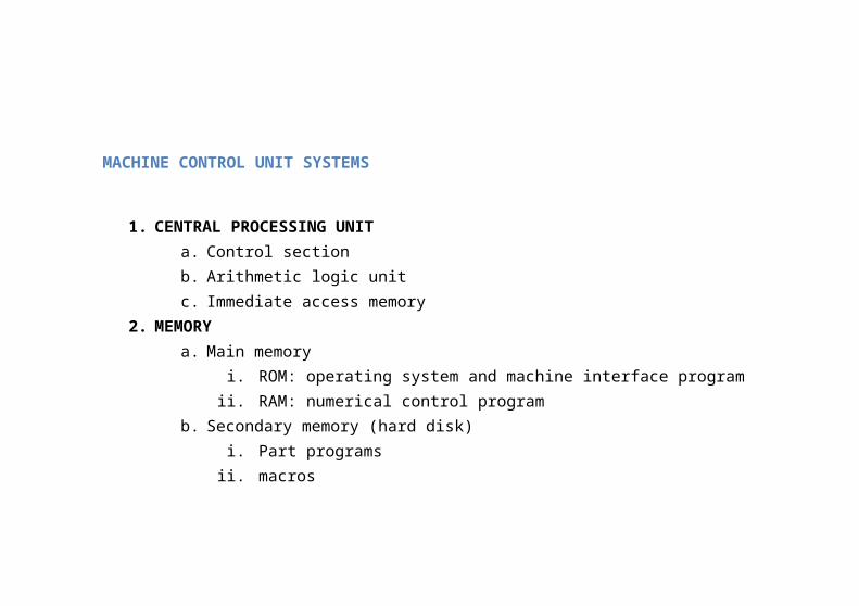
MACHINE CONTROL UNIT SYSTEMS
1. CENTRAL PROCESSING UNITa. Control sectionb. Arithmetic logic unitc. Immediate access memory
2. MEMORYa. Main memory
i. ROM: operating system and machine interface programii. RAM: numerical control program
b. Secondary memory (hard disk)i. Part programs
ii. macros3. I/O INTERFACE
Communication between various components of CNC system

a. Operator panelb. Tape readerc. Display
4. CONTROL FOR MACHINE TOOL AXES AND SPINDLE SPEEDc. Position controld. Spindle speed control
5. SEQUENCE CONTROL for others machine tool function
e. Coolantf. Fixtures clampingg. Tool charger (ATC)