22-23 august 2014, koc university, …conf-scoop.org/ace-2014/3_basaeri_ace.pdfposition control of...
TRANSCRIPT
Position Control of Shape Memory Alloy Actuators
Using a Phenomenological Hysteresis Model
Hamid Basaeri
Graduate Student,
Center of Advanced Systems and Technologies (CAST)
School of Mechanical Engineering, College of Engineering,
University of Tehran, Tehran, Iran
Aghil Yousefi-Koma
Professor,
Center of Advanced Systems and Technologies (CAST)
School of Mechanical Engineering, College of Engineering,
University of Tehran, Tehran, Iran
Mohammad Reza Zakerzadeh
Assistant Professor,
Center of Advanced Systems and Technologies (CAST)
School of Mechanical Engineering, College of Engineering,
University of Tehran, Tehran, Iran
Seyed Saeid Mohtasebi
Professor,
Center of Advanced Systems and Technologies (CAST)
School of Mechanical Engineering, College of Engineering,
University of Tehran, Tehran, Iran
Abstract—Shape Memory Alloy (SMA) actuators are
hysteretic nonlinear materials, and thus it is difficult to
effectively utilize these actuators. As a result of these effects, the
position control of these type of actuators has been a great
challenge in recent years. Using the phenomenological hysteresis
models can compensate the hysteresis of these actuators
effectively. In this paper, a feedback controller was used to
control the rotation angle of a morphing wing mechanism
actuated by an SMA actuator wire. Results showed that the
proposed controller performed well in terms of attaining small
overshoot and undershoot for square wave tracking as well as
small tracking errors for sinusoidal trajectory. It has also good
capability for tracking hysteresis minor loops.
Keywords—shape memory alloy; phenomenological hysteresis
model; feedback control system
I. INTRODUCTION
Since the main difficulty in controlling Shape Memory Alloy (SMA) materials is due to their nonlinear saturated hysteretic behavior during forward and reverse transformations, position and force controls of these materials have been a great challenge for practical applications during the last decade. Steady state errors and limit cycle problems are some results of this behavior when conventional controllers are used for trajectory control [1]. Also, while for slowly varying reference signals, and with properly tuned gains, feedback strategies such as Proportional–Integral (PI) control can provide adequate performance, oscillatory motions about the reference trajectory often occur for the fast reference signals [2]. Because of these reasons, recent researches on control of SMA actuators have been guided to follow the nonlinear methods.
In order to reduce the energy consumption by the SMA actuators, PWM controllers are appropriate choices as position
controller. Ma and Song [3] concluded, by experimental results, that using Pulse Width Modulation (PWM) for controlling an SMA actuator efficiently saves actuation energy while keeping the same control accuracy as compared to a conventional PD controller. In ref. [4] a simple proportional controller was applied in active shape control of a flexible beam. It was shown by experimental data that in order to eliminate the steady state error of a step input signal, overshoot and actuator saturation are unavoidable. Experimental results showed that among the linear controllers, PI with anti-windup has the best results for position control of SMA actuators [5].
In another method, the hysteresis can be modeled by the use of one of phenomenological hysteresis models like Preisach model, Krasnosel’skii–Pokrovskii model and Prandtl–Ishlinskii model. As these models are defined by integral of hysteresis operators over a specified region, they have more capabilities in modeling of the systems with hysteresis behavior like SMA actuators. Due to the simplicity and availability of the standard controllers in the industrial world, using PI and PID controllers for systems with hysteretic behavior has attracted many researches. In [6], the stability properties of a plant described by a feedback interconnection of a linear system and a Bouc-Wen hysteresis model was investigated and controlled by a PID control system. In another work, the PI control system design for a plant that was purely hysteretic, i.e., without any dynamics, was discussed [7]. It offers a simple bound on the controller gains and it applies to several models. Nevertheless, ignoring the dynamic phenomena leads to satisfactory results only at low frequencies.
In this paper, the generalized Prandtl–Ishlinskii (P-I) hysteresis model is used for modeling the hysteresis of SMA actuator and the position regulation control of the actuator is
Scientific Cooperations International Workshops on Electrical and Computer Engineering Subfields 22-23 August 2014, Koc University, ISTANBUL/TURKEY
13

performed by using this model with a PI controller. In what follows, the generalized Prandtl-Ishlinskii model is presented and used to model a mechanism actuated by shape memory alloys. The P-I model is trained by the use of some experimental data in order to identify some unknown parameters of the model. The experimental data is obtained from the test setup consisting of a morphing wing mechanism actuated by shape memory alloy wires [11]. The identification process is implemented in order to adapt the model response to the real hysteretic nonlinearity. After that, the controller design is explained and the accuracy of this controller is studied for different inputs like square and sinusoidal waves.
II. GENERALIZED PRANDTL-ISHLINSKII MODEL
The classical Prandtl-Ishlinskii (P-I) model uses the
classical play (or stop) operator with a density function to
characterize the hysteretic behavior of materials. This
operator, characterized by the input u and the threshold r
determining the width of the hysteresis operator, is a
continuous rate-dependent operator which further details about
it can be found in [8]. Assume that Cm[0,T] is the space of the
piecewise monotone continuous functions and the input
u(t)∈Cm[0,T] is monotone on each of the sub-intervals [ti,t(i+1)],
where t0<t1<⋯<ti<t(i+1)<⋯<tN=T. Then the output of the
generalized P-I model, ygeneralized, can be obtained as follows
[9]:
0( ) (r)S [ ]( )
R
generalized ry t p u t dr (1)
In this equation, p(r) is an integrable positive density
function, r is the positive threshold as
r0<r1<⋯<ri<r(i+1)<⋯<rN=R, and Sr[u] is the generalized play
hysteresis operator that is analytically expressed as:
[ ](0) (u(0),0)
S [ ](t) ( ( ), [ ]( ))
r r
r r r i
S u g
u g u t S u t
(2)
where gr(u,z)=max{γl(u)-r,min(γr(u)-r,z)}. In the case of
practical applications where a finite number of generalized
hysteresis play operators is used, Eq. (1) would be expressed
as:
0
(k) (r)S [ ](k)i
N
generalized r
i
y p u
(3)
According to Eqs. (1) and (3), the generalized Prandtl–
Ishlinskii model output depends on the shape of envelope,
density and threshold functions. Generally, the shapes of these
functions are defined based on the hysteresis loop of a
particular material and considering that whether such material
has asymmetric hysteresis loops and (or) output saturation or
not. Also, the output of the mentioned functions strongly
depends on the parameters of these functions. Therefore, these
parameters should be obtained on the basis of some
experimental data of the actuator in order to correctly predict
the behavior of such materials. Due to some good properties of
hyperbolic tangent functions [9], in this work, the following
functions are selected for the envelope functions of the
generalized play operator:
1 2 3 4( ) tanh( )r u P Pu P P (4)
5 6 7 8( ) tanh( )l u P Pu P P (5)
Also, the following forms are selected for the density and
threshold functions [10]:
10
9 ( 0,1,..., )jP r
jp Pe j N
(6)
11 ( 0,1,..., )jr P j j N (7)
In order to implement the generalized Prandtl–Ishlinskii
hysteresis model for behavior prediction of a particular SMA
actuator, first the above mentioned 11 constants, including P1,
P2, . . . , P11, should be identified using the measured input–
output experimental data. In the current research, this process,
called training process, is performed with the MATLAB
optimization Toolbox. The goal is to have minimum errors
with respect to the experimental data. In this paper, the
experimental data are collected from an experimental test set-
up, consisting of a mechanism actuated by a shape memory
alloy wire, and the details about this set-up will be explained
in the following section.
III. EXPERIMENTAL TEST SETUP
The experimental setup which is shown in Fig. 1 consists of
a mechanism that is appropriate for morphing wing
applications. In other words, this mechanism can be used in a
wing so that the wing shape can be changed at different flight
conditions [11].
A PC-based experimental test setup and its associated
instruments are used to investigate the capability of the
generalized Prandtl–Ishlinskii model in prediction of the
proposed morphing wing mechanism behavior under a SMA
wire actuation. Moreover, the schematic interconnection of
these components is depicted in Fig. 2. The experimental setup
consists of the test-bed (the morphing wing mechanism
equipped with SMA wires and two potentiometers, mounted
on a test stand), a data acquisition system, a Windows-based
PC, required electronic circuits (bridge circuitry with
instrumentation amplifier and antialiasing filter, and voltage-
controlled current amplifier circuits) and a power supply.
The main properties of the SMA wires which are used as
actuators are presented in Table I. The SMA actuators are
made of Nitinol (Ni-Ti) alloy which has excellent electrical
and mechanical properties, long fatigue life, and high
corrosion resistance and due to these properties, this material
is used in many SMA actuators today [12]. Finally, the
Scientific Cooperations International Workshops on Electrical and Computer Engineering Subfields 22-23 August 2014, Koc University, ISTANBUL/TURKEY
14

specifications of the experimental setup which is used to
verify the results of P-I model are listed in Table II.
Fig. 1. A View of fabricated morphing wing test setup.
Power SupplyPC Data Acquisition
Board
Wing Section
Fig. 2. Schematic diagram of the experimental setup.
TABLE I. PROPERTIES OF SHAPE MEMORY ALLOY ACTUATOR.
Coefficient Definition Value Unit
dw Diameter 0.01 In
ρ Density 6.45 g/cm3
Mf Martensite final temperature 43.9 ᵒC
Ms Martensite start temperature 48.4 ᵒC
Af Austenite final temperature 68 ᵒC
As Austenite start temperature 73.75 ᵒC
TABLE II. SOME SPECIFICATIONS OF THE EXPERIMENTAL SETUP [11].
Test-Bed
Morphing wing mechanism with 0.01” NiTi
Flexinol wires & potentiometer pair,
A test-stand
Data Acquisition National Instrument, SCB-68 Noise Rejecting,
Shielded I/O, Connector Block
PC Hardware Core2 Duo 2 GHz CPU, 2GB RAM
Software Windows 7, LabVIEW
Circuits
Bridge circuitry with instrumentation amplifying
and anti-aliasing filter,
Voltage-controlled current amplifier circuit
IV. IDENTIFICATION AND VALIDATION PROCESSES
In order to train the model, a slow decaying ramp signal which
is illustrated in fig. 3 is applied to the SMA wire actuator and
is defined as the input voltage. The rate of change of the input
voltage is carefully chosen to be so small. To train the
generalized P-I model, 642 data set which contains the major
loop and 10 first order descending reversal curves attached to
the major loop is used. The switching values of these
descending reversal curves are selected as: [3.5, 3.1, 3, 2.9,
2.8, 2.7, 2.6, 2.5, 2.4, 2.3, and 2.2] (volt). The input voltage to
the mechanism is shown in Fig. 3. For switching values less
than 2.2 (volt), the change in the mechanism rotation is
negligible.
0 100 200 300 400 500 600 7000
0.5
1
1.5
2
2.5
3
3.5
Time (s)
Vo
ltag
e (
v)
Fig. 3. The decaying ramp input voltage applied in the training process.
The experimental input-output hysteresis loops of the
morphing wing mechanism with SMA wire actuator, under the
above mentioned input voltage is depicted in Fig. 4. The
identification process is implemented in the P-I model and, the
11 generalized P-I model parameters are identified by using
MATLAB optimization Toolbox in order to minimize the
error between the model output and the experimental data.
These values are tabulated in Table III. Since, unlike other
hysteresis models, the Prandtl-Ishlinskii model does not have
exact output even for the training data, the output of the
generalized P-I model in time domain under the actuation
voltage profile of Fig .3, is compared with the experimental
data shown in Fig. 5. This figure obviously depicts that the
generalized P-I model, with selected envelope, density and
threshold functions and their corresponding parameters in
Table III, can effectively characterized the behavior of the
morphing wing mechanism with SMA wire actuation and
there are only small differences for some data.
In order to show the accuracy of modeling prediction more
clearly, the maximum, mean and mean squared values of the
absolute error are also presented in Table IV. Since the
maximum rotation of the mechanism under the SMA wire
actuation is around 16 degrees, the peak prediction error in
this case is about 9.33% of the maximum output.
Scientific Cooperations International Workshops on Electrical and Computer Engineering Subfields 22-23 August 2014, Koc University, ISTANBUL/TURKEY
15

TABLE III. PARAMETERS OF GENERALIZED PRANDTL-ISHLINSKII MODEL
IDENTIFIED BY THE MEASURED EXPERIMENTAL DATA OF SMA-ACTUATED
MECHANISM.
P1 3.3784 P2 1.6268 P3 -3.7776
P4 1.5592 P5 3.7571 P6 1.7893
P7 -4.0901 P8 -1.1545 P9 0.5657
P10 0.3016 P11 0.1378
0 100 200 300 400 500 600 7000
2
4
6
8
10
12
14
16
18
Time (s)
Ro
tati
on
An
gle
(d
eg
)
PI Model
Experiment
Absolute Error
Fig. 4. Comparison between the mechanism rotation predicted by the
generalized Prandtl–Ishlinskii model and the measured data.
TABLE IV. ERROR OF THE GENERALIZED PRANDTL–ISHLINSKII MODEL IN
THE TRAINING PROCESS.
Mean of Absolute Error
(deg)
Max of Absolute Error
(deg)
Mean of Squared Error
(deg)
0.21 1.52 0.11
Most of the phenomenological hysteresis models have
trouble in predicting higher order hysteresis minor loops. For
evaluating the ability of generalized P-I model under these
circumstances, in the validation process a damped voltage
profile shown in Fig. 6 is applied to the current amplifier of
the SMA actuator.
The predictions of the higher order hysteresis minor loops
by the generalized P-I model are compared with the
experimental measured data in Fig. 7. The absolute error
response with respect to measured data, in time domain, is
also presented in Fig. 8. The maximum, mean and mean
square values of the absolute error are also presented in Table
V. The peak prediction error in this case is about 17.1% of the
maximum output.
0 50 100 150 200 2500
0.5
1
1.5
2
2.5
3
3.5
Time (s)
Vo
ltag
e (
v)
Fig. 5. The input voltage profile applied in the validation process.
0 50 100 150 200 2500
2
4
6
8
10
12
14
16
18
Time (s)
Ro
tati
on
An
gle
(d
eg
)
PI Model
Experiment
Fig. 6. Comparison between the rotation response of the generalized Prandtl-
Ishlinskii model and the measured data in the validation process.
0 50 100 150 200 2500
0.5
1
1.5
2
Time (s)
Ab
so
lute
Err
or
(deg
)
Fig. 7. Time history of absolute error between the generalized Prandtl-
Ishlinskii model and experimentally measured data in the validation process.
As it was anticipated and it is observable from Fig. 7 and
Table V, the generalized P-I model has adequate accuracy in
predicting the higher order hysteresis minor loops particularly
when, like this case, it has been only trained with some first
order hysteresis reversal curves attached to the major loop.
TABLE V. ERROR OF THE GENERALIZED PRANDTL–ISHLINSKII MODEL
IN THE VALIDATION PROCESS.
Mean of Absolute
Error (deg)
Max of Absolute Error
(deg)
Mean of Squared Error
(deg)
0.46 1.79 0.38
Scientific Cooperations International Workshops on Electrical and Computer Engineering Subfields 22-23 August 2014, Koc University, ISTANBUL/TURKEY
16

V. CONTROL
As the generalized Prandtl–Ishlinskii model has more accuracy for hysteresis modeling of SMA actuator with respect to Preisach and Krasnosel’skii–Pokrovskii hysteresis models [13], especially for high order minor loop prediction, in this paper, the generalized Prandtl–Ishlinskii model is used for compensating the hysteresis nonlinearity of SMA-actuated morphing wing mechanism. The block diagram of the proposed controller is shown in Fig. 9. The desired rotation is used as the input. The PI controller generates the required control voltage signal for the desired trajectory tracking. The gains of the PI feedback controller, denoted by KI and KP respectively, are 0.1 and 0.3. The values of these gains are set in such a way that system response to step reference trajectory has the minimum overshoot as well as quick response.
Generalized Prandtl-
Ishlinskii Model
Reference
Signal+
PI
Controller-
error SMA input
voltage
Mechanism Rotation
Fig. 8. Closed-loop scheme with a PI controller.
In order to show the effectiveness of the proposed control system for hysteresis compensation together with accurate position control of morphing wing mechanism, four sets of reference signals are selected for this controller verification process and the results of each test are presented later in this section.
A. Square wave tracking with fixed lower bound
As stated in Section IV, the generalized Prandtl–Ishlinskii
hysteresis model is trained with the data of first order reversal
descending curves attached to the ascending branch of the
major loop. The purpose of the current experiment test is to
verify the ability of the proposed controller in tracking a
square waveform trajectory, which leads to predict some first
order reversal curves behavior by the hysteresis model. The
set-point values of desired rotation are chosen as: [16, 15, 13,
12, 10, 8, and 6] (volt). Fig. 10 shows the responses of the
proposed control system. Fig. 11 also illustrates the SMA
voltage over time in this test.
As it is obvious, the proposed control system can
accurately track the reference trajectory with minimum
oscillation and also eliminates the steady state errors.
0 100 200 300 400 500 6000
2
4
6
8
10
12
14
16
18
Time (s)
Ro
tati
on
An
gle
(d
eg
)
Reference Input
PI Controller
Fig. 9. Tracking control of a square wave with fixed lower bound.
0 100 200 300 400 500 6000
0.5
1
1.5
2
2.5
3
3.5
Time (s)
SM
A V
olt
ag
e (
v)
Fig. 10. SMA voltages during tracking of a square wave with fixed lower
bound.
B. Square wave tracking with high order minor loops
Since many hysteresis models proposed in the literature
failed to track high order minor hysteresis loops, in this
experiment the response of the proposed control system is
verified in tracking a square waveform trajectory with variable
amplitude which leads to some minor hysteresis loop
prediction. The set-point values of desired deflections are
chosen as: [17, 2, 15, 4, 13, 7, 12, and 9] (volt). Fig. 12 depicts
the performance of the developed control system in tracking
such reference rotation signal. Furthermore, the control signal
applied by the control system to the SMA actuator can be
observed in Fig. 13.
While the generalized Prandtl–Ishlinskii model was only
trained by data of some first order reversal curves of voltage–
rotation hysteresis loops, the controller has moderate accuracy
in tracking the desired deflection. Due to controller good
performances, the steady state error has been easily eliminated
by the closed-loop conventional PI controller and the system
has minimum oscillations about the set points of desired
signal. As a conclusion, against many control systems that
have difficulties in minor hysteresis loops tracking, the
Scientific Cooperations International Workshops on Electrical and Computer Engineering Subfields 22-23 August 2014, Koc University, ISTANBUL/TURKEY
17

accuracy of this control system is excellent without using any
data of minor hysteresis loops in the training process.
0 50 100 150 2000
2
4
6
8
10
12
14
16
18
Time (s)
Ro
tati
on
An
gle
(d
eg
)
Reference Input
PI Controller
Fig. 11. Tracking control of a square wave with high order minor loops
0 50 100 150 2000
0.5
1
1.5
2
2.5
3
3.5
4
Time (s)
SM
A V
olt
ag
e (
v)
Fig. 12. SMA voltages during tracking control of a square wave with high
order minor loops.
C. Tracking of a fixed amplitude sinusoidal input
In the current test, the reference input signal is a sinusoidal
trajectory with fixed amplitude. Time functionality of this
input is selected as 12sin(0.02*time - π/2)+12 which leads to a
hysteresis loop prediction with no higher order minor loops in
it. The result of the proposed control system is investigated
and shown in Fig. 14. Also, Fig. 15 illustrates the SMA
voltage over time in this test. The proposed control system can
accurately track the reference trajectory with minimum
oscillation. This will be clearer when the absolute value of the
rotation error is depicted over time in Fig. 16. The absolute
error average for the proposed control system is 0.43 degree.
0 100 200 300 400 500 6000
2
4
6
8
10
12
14
16
18
Time (s)
Ro
tati
on
An
gle
(d
eg
)
Reference Input
PI Controller
Fig. 13. Tracking control of a sinusoidal wave with a fixed amplitude.
0 100 200 300 400 500 6000
0.5
1
1.5
2
2.5
3
3.5
4
Time (s)
SM
A V
olt
ag
e (
v)
Fig. 14. SMA voltages during tracking control of a sinusoidal wave with a
fixed amplitude.
0 100 200 300 400 500 6000
0.5
1
1.5
2
2.5
Time (s)
Tra
ckin
g E
rro
r (d
eg
)
Fig. 15. Absolute of tracking error in tracking control of a sinusoidal wave
with a fixed amplitude.
D. Tracking of a decaying sinusoidal reference input
In the last test, the reference input signal is a decaying
sinusoidal trajectory which results to predicting some high
order minor hysteresis loop by the hysteresis model. The time
functionality of this input is selected as (12sin(0.02*time -
π/2)+12)*exp(-0.005*time) which not only is a decaying input
but also its variation with respect to time is almost fast. Thus,
the system response to this decaying input can verify the good
performance of the controller. The result of the proposed
Scientific Cooperations International Workshops on Electrical and Computer Engineering Subfields 22-23 August 2014, Koc University, ISTANBUL/TURKEY
18
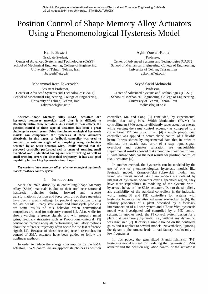
control system is shown in Fig. 17. The system has only weak
tracking in the extremum regions of the reference input in
which its derivative sign changes. Moreover, the control signal
applied by the control system to the SMA actuator is shown in
Fig. 18, and the absolute value of the rotation error over time
is displayed in Fig. 19. The absolute error average for the
proposed control system is 0.28 degree. It should be noted that
this worth result is obtained by only training the Prandtl–
Ishlinskii hysteresis model with the data of some first order
reversal curves. It means that whether the generalized Prandtl–
Ishlinskii model is trained by the first order reversal curves
data or is trained by higher order minor loops data, the model
has good prediction of the high order minor hysteresis loops of
SMA actuator.
0 100 200 300 400 500 600 7000
2
4
6
8
10
12
14
16
18
Time (s)
Ro
tati
on
An
gle
(d
eg
)
Reference Input
PI Controller
Fig. 16. Tracking control of a decaying sinusoidal wave.
0 100 200 300 400 500 6000
0.5
1
1.5
2
2.5
3
3.5
4
Time (s)
SM
A V
olt
ag
e (
v)
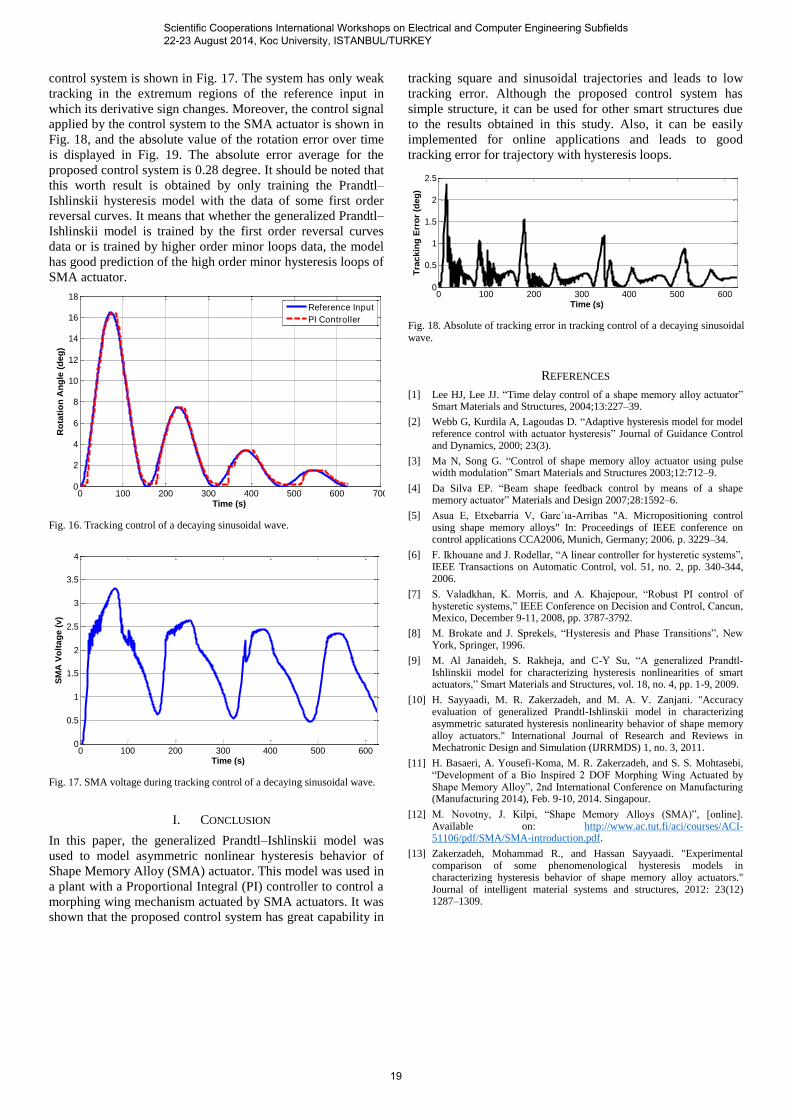
Fig. 17. SMA voltage during tracking control of a decaying sinusoidal wave.
I. CONCLUSION
In this paper, the generalized Prandtl–Ishlinskii model was
used to model asymmetric nonlinear hysteresis behavior of
Shape Memory Alloy (SMA) actuator. This model was used in
a plant with a Proportional Integral (PI) controller to control a
morphing wing mechanism actuated by SMA actuators. It was
shown that the proposed control system has great capability in
tracking square and sinusoidal trajectories and leads to low
tracking error. Although the proposed control system has
simple structure, it can be used for other smart structures due
to the results obtained in this study. Also, it can be easily
implemented for online applications and leads to good
tracking error for trajectory with hysteresis loops.
0 100 200 300 400 500 6000
0.5
1
1.5
2
2.5
Time (s)
Tra
ckin
g E
rro
r (d
eg
)
Fig. 18. Absolute of tracking error in tracking control of a decaying sinusoidal
wave.
REFERENCES
[1] Lee HJ, Lee JJ. “Time delay control of a shape memory alloy actuator” Smart Materials and Structures, 2004;13:227–39.
[2] Webb G, Kurdila A, Lagoudas D. “Adaptive hysteresis model for model reference control with actuator hysteresis” Journal of Guidance Control and Dynamics, 2000; 23(3).
[3] Ma N, Song G. “Control of shape memory alloy actuator using pulse width modulation” Smart Materials and Structures 2003;12:712–9.
[4] Da Silva EP. “Beam shape feedback control by means of a shape memory actuator” Materials and Design 2007;28:1592–6.
[5] Asua E, Etxebarria V, Garc´ıa-Arribas "A. Micropositioning control using shape memory alloys" In: Proceedings of IEEE conference on control applications CCA2006, Munich, Germany; 2006. p. 3229–34.
[6] F. Ikhouane and J. Rodellar, “A linear controller for hysteretic systems”, IEEE Transactions on Automatic Control, vol. 51, no. 2, pp. 340-344, 2006.
[7] S. Valadkhan, K. Morris, and A. Khajepour, “Robust PI control of hysteretic systems,” IEEE Conference on Decision and Control, Cancun, Mexico, December 9-11, 2008, pp. 3787-3792.
[8] M. Brokate and J. Sprekels, “Hysteresis and Phase Transitions”, New York, Springer, 1996.
[9] M. Al Janaideh, S. Rakheja, and C-Y Su, “A generalized Prandtl- Ishlinskii model for characterizing hysteresis nonlinearities of smart actuators,” Smart Materials and Structures, vol. 18, no. 4, pp. 1-9, 2009.
[10] H. Sayyaadi, M. R. Zakerzadeh, and M. A. V. Zanjani. "Accuracy evaluation of generalized Prandtl-Ishlinskii model in characterizing asymmetric saturated hysteresis nonlinearity behavior of shape memory alloy actuators." International Journal of Research and Reviews in Mechatronic Design and Simulation (IJRRMDS) 1, no. 3, 2011.
[11] H. Basaeri, A. Yousefi-Koma, M. R. Zakerzadeh, and S. S. Mohtasebi, “Development of a Bio Inspired 2 DOF Morphing Wing Actuated by Shape Memory Alloy”, 2nd International Conference on Manufacturing (Manufacturing 2014), Feb. 9-10, 2014. Singapour.
[12] M. Novotny, J. Kilpi, “Shape Memory Alloys (SMA)”, [online]. Available on: http://www.ac.tut.fi/aci/courses/ACI-51106/pdf/SMA/SMA-introduction.pdf.
[13] Zakerzadeh, Mohammad R., and Hassan Sayyaadi. "Experimental comparison of some phenomenological hysteresis models in characterizing hysteresis behavior of shape memory alloy actuators." Journal of intelligent material systems and structures, 2012: 23(12) 1287–1309.
Scientific Cooperations International Workshops on Electrical and Computer Engineering Subfields 22-23 August 2014, Koc University, ISTANBUL/TURKEY
19