2150080 2g actuator packets - rotary & linear capitol drive suite #103 sun prairie, wi 53590...
TRANSCRIPT

2752 Capitol Drive Suite #103 Sun Prairie, WI 53590
2150080 2G Actuator Packets - Rotary & Linear Revision AI Date 4/25/2018
2G Actuator Communications Protocol Document – Rotary & Linear Actuators
DOCUMENT NO. 2150080
Rev. AI
Date: 4-25-2018
Prepared by:
2G Engineering 2752 Capitol Drive Suite #103
Sun Prairie WI, 53590

2
REVISION HISTORY
REV DATE Editor DESCRIPTION
- 6-29-2015 JL Initial Release
A 8-12-2015 JL Updated Scaled Position; Failsafe mode packets
B 8-13-2015 JL Updated system status/info and motor control packets
C 8-17-2015 JL Updated byte counts and byte numbering on several packets
D 9-2-2015 JL Updated documentation on Version packet and System Configuration packets
E 9-28-2015 AT Incorporated new template for packet specifications. Updated System Configuration packets.
F 9-30-2015 JL Updated Position Setpoint at Fixed Velocity, Scaled Position Setpoint, and System Configuration Packets.
G 10-1-2015 JL Added information about ASCII packet protocol, updated port activation section.
H 10-1-2015 JL Added Version and Build Info packets.
I 10-9-2015 JL Updated data type information, added note to system info packet, added note to velocity packet, updated index.
J 11-3-2015 JL Added motion profile configuration packet. Updated ‘K’ packet.
K 11-10-2015 JL Added position update packet. Updated ‘<’ packet. Added note on CRC.
L 11-12-2015 JL Updated position update packet.
M 12-31-2015 JL
Updated Basic Packet Behavior section. Added note on analog control to RS-485 and RS-232 Port Activation section. Updated Motion Profile Config packet. Added Motion Profile Status packet. Updated Firmware Build Info packet.
N 1-25-2016 JL Updated Failsafe Config packet with copy to global config. Added EEPROM status bit to faults packet.
O 1-29-2016 JL Updated bits in fault packet. Added current offset packet.
P 2-2-2016 JL Added Load Dump Configuration packet. Added Stall Detection Configuration packet.
Q 3-3-2016 JL Updated Calibrate / Configure Position Packet ‘C’.

3
Updated Fault behavior packet ‘O’. Updated Motion Profile Configuration – Linear units.
R 4-6-2016 JL Updated Load Dump Packet, Absolute Position, Failsafe, Failsafe time remaining, hardware brake configuration packets.
S 5-13-2016 JL Added Gain Scheduling Packet.
T 5-16-2016 JL Corrected Rotary - System Info Packet
U 6-16-2016 JL
Corrected error in Rotary - System Info Packet. Updated Stall Detection Configuration Packet. Updated Fault Information Packet. Updated Fault History Information Packet.
V 7-20-2016 JL Added additional information to Basic Packet Behavior section and RS485 Termination Configuration Packet.
W 8-18-2016 JL Updated load dump packet.
X 10-6-2016 JL Added raw position packets and linearization configuration packets.
Y 11-9-2016 JL Updated position linearization configuration packet.
Z 12-13-2016 JL Corrected position units on Absolute Setpoint Packet ‘S’
Added Auto-Info Configuration Packet.
AA 1-24-2017 JL Added persistent revolution counting configuration packet. Updated clear offsets packet and update position packet.
AB 4-12-2017 JL Updated units on Rotary System Configuration 2 Packet ‘D’
AC 4-24-2017 JL Added PID Feed Forward configuration to System Configuration 3 packet.
AD 6-8-2017 JL Updated Linear Actuator Position Sampling Configuration Packet.
AE 2-2-2018 JL Added Velocity Setpoint Extended Packet. Corrected size of Current Limit Configuration Packet.
AF 2-15-2018 JL Added note on HPU operation.
AG 2-26-2018 JL Added documentation for stall detection on linear actuators
AH 3-7-2018 JL Corrected field ordering and labeling on system configuration 1 and 2 packets
AI 4-25-2018 JL Corrected model identifier table in acknowledge packet. Added actuator name, CAN configuration, and CAN status packets.

4
1 Contents
2 Servo System Overview ................................................................................................................................. 8
3 Packet Format Overview ............................................................................................................................... 9
3.1 Standard (Non-Addressed) Packets .............................................................................................................. 9
3.2 Addressed Packets ........................................................................................................................................ 9
3.3 ASCII Packets ................................................................................................................................................ 9
4 Basic Packet Behavior .................................................................................................................................. 11
5 RS-485 and RS-232 Port Activation .............................................................................................................. 11
6 Data Types................................................................................................................................................... 11
7 Units ............................................................................................................................................................ 12
7.1 Linear Actuators ......................................................................................................................................... 12
7.2 Rotary Actuators ........................................................................................................................................ 12
8 Storage of Configuration Parameters .......................................................................................................... 12
9 System Settings ........................................................................................................................................... 12
10 Actuator Movement Methods ..................................................................................................................... 13
11 HPU Operation ............................................................................................................................................ 13
12 System Parameter and Packet Lookup Table ............................................................................................... 14
13 Packet Specifications ................................................................................................................................... 18
14 Configuration Packets ................................................................................................................................. 18
14.1 Linear Actuators - Absolute Position Setpoint Packet ‘S’ ............................................................................ 18
14.2 Rotary Actuators - Absolute Position Setpoint Packet ‘S’ ........................................................................... 19
14.3 Baud Rate Configuration Packet ‘B’ ........................................................................................................... 20
14.4 Communication Address Configuration Packet ‘Y’ ..................................................................................... 21
14.5 Current Limits Configuration Packet ‘I’ ...................................................................................................... 22
14.6 Linear Actuators - Failsafe Configuration Packet 0x92 .............................................................................. 23
14.7 Rotary Actuators - Failsafe Configuration Packet 0x92 .............................................................................. 25
14.8 Fault Behavior Configuration Packet ‘O’ .................................................................................................... 27
14.9 Hardware Brake Configuration Packet 0x86 .............................................................................................. 28
14.10 Motor Control Configuration Packet ‘X’ ................................................................................................. 29
14.11 Overvoltage Protection Configuration Packet 0x82 ............................................................................... 31
14.12 Linear Actuators - Position Sampling Configuration Packet ‘E’ .............................................................. 32

5
14.13 Rotary Actuators - Position Sampling Configuration Packet ‘E’ ............................................................. 34
14.14 Linear Actuators - Position Setpoint at Fixed Velocity Configuration Packet ‘U’ ................................... 36
14.15 Rotary Actuators - Position Setpoint at Fixed Velocity Configuration Packet ‘U’................................... 37
14.16 Linear Actuators - Position Setpoint at Fixed Velocity Extended Configuration Packet ‘K’ .................... 38
14.17 Rotary Actuators - Position Setpoint at Fixed Velocity Extended Configuration Packet ‘K’ ................... 40
14.18 Linear Actuators – Relative Position Setpoint Packet ‘R’ ....................................................................... 42
14.19 Linear Actuators - Relative Zero Position Configuration Packet ‘Z’ ........................................................ 43
14.20 RS485 Termination Configuration Packet 0x84 (Actuators equipped with RS485 Only)........................ 44
14.21 Scaled Position Setpoint Configuration Packet 0x88 (Actuators equipped with position scaling only) . 45
14.22 Linear Actuators - System Configuration 1 Packet ’M’ .......................................................................... 46
14.23 Rotary Actuators - System Configuration 1 Packet ’M’ .......................................................................... 48
14.24 Linear Actuators - System Configuration 2 Packet ‘D’ ........................................................................... 50
14.25 Rotary Actuators - System Configuration 2 Packet ‘D’ ........................................................................... 52
14.26 Linear Actuators – System Configuration 3 Packet 0xA6 ....................................................................... 54
14.27 Rotary Actuators – System Configuration 3 Packet 0xA6 ...................................................................... 56
14.28 Valve Endpoints Configuration Packet 0x80 (Ball Valve Actuators Only) .............................................. 58
14.29 Linear Actuators – Velocity Setpoint Configuration Packet ‘W’ ............................................................. 59
14.30 Rotary Actuators – Velocity Setpoint Configuration Packet ‘W’ ............................................................ 60
14.31 Linear Actuators – Velocity Setpoint Extended Configuration Packet 0xB6 ........................................... 61
14.32 Rotary Actuators – Velocity Setpoint Extended Configuration Packet 0xB6 .......................................... 62
14.33 Linear Actuators – Motion Profile Configuration Packet 0x9A .............................................................. 63
14.34 Rotary Actuators – Motion Profile Configuration Packet 0x9A .............................................................. 66
14.35 Rotary Actuators – Load Dump Configuration Packet 0xA4 .................................................................. 69
14.36 Rotary Actuators – Stall Detection Configuration Packet 0xA8 ............................................................. 72
14.37 Linear Actuators – Stall Detection Configuration Packet 0xA8 .............................................................. 74
14.38 Rotary Actuators – Gain Scheduling Configuration Packet 0xAB ........................................................... 76
14.39 Linear Actuators – Gain Scheduling Configuration Packet 0xAB ........................................................... 79
14.40 Rotary Actuators – Position Linearization Configuration Packet 0xAD .................................................. 82
14.41 Rotary Actuators – Raw Position Packet 0xAF ....................................................................................... 84
14.42 Auto-Info Configuration Packet 0xB2 .................................................................................................... 86
14.43 Rotary Actuators – Persistent Revolution Counting Configuration Packet 0xB4 ................................... 88
14.44 CAN Bus Configuration Packet 0xB8 (Actuators equipped with CAN only) ............................................ 89
14.45 Actuator Name Packet 0xBC .................................................................................................................. 91
15 Information Packets .................................................................................................................................... 92
15.1 Acknowledgement Packet ‘A’ ..................................................................................................................... 92

6
15.2 Failsafe Time Remaining Information Packet 0x94 .................................................................................... 94
15.3 Fault History Information Packet ‘N’ .......................................................................................................... 95
15.4 Fault Information Packet ‘F’ ....................................................................................................................... 97
15.5 Firmware Build Information Packet 0x96 ................................................................................................... 99
15.6 Firmware Version Number Packet ‘?’ ....................................................................................................... 101
15.7 Scaled Position Information Packet 0x90 ................................................................................................. 102
15.8 Linear Actuators - System Status Information Packet ‘P’ ......................................................................... 103
15.9 Rotary Actuators - System Status Information Packet ‘P’ ........................................................................ 105
15.10 System Status Information 2 Packet 0xA2 ........................................................................................... 108
15.11 Linear Actuators – Velocity Information Packet ‘H’ ............................................................................. 111
15.12 Rotary Actuators – Velocity Information Packet ‘H’ ............................................................................ 112
15.13 Motion Profile Status Packet 0x9C ....................................................................................................... 113
15.14 CAN Bus Status Packet 0xBA (Actuators equipped with CAN only) ...................................................... 114
16 Command Packets ..................................................................................................................................... 115
16.1 Linear Actuators – Calibrate / Configure Position Packet ‘C’ ................................................................... 115
16.2 Rotary Actuators – Calibrate / Configure Position Packet ‘C’ ................................................................... 116
16.3 Calibrate / Configure Current Packet 0xAA .............................................................................................. 117
16.4 Clear Offsets Command Packet ‘-‘ ............................................................................................................ 118
16.5 In-System Programming Update Command Packet ‘~‘ ............................................................................ 119
16.6 Load Default (Factory) Configuration Command Packet ‘@‘ ................................................................... 120
16.7 Reset Faults Command Packet ‘!‘ ............................................................................................................. 121
16.8 Rotary Actuators - Reset Rotary Counters Command Packet ‘<‘ .............................................................. 122
16.9 Reset System Command Packet ‘=‘ .......................................................................................................... 123
16.10 Reverse Direction Command Packet ‘&’............................................................................................... 124
16.11 Save Configuration to EEPROM Command Packet ‘$‘.......................................................................... 125
16.12 Set Duty Cycle Command Packet ‘+’ .................................................................................................... 126
16.13 Set Match Value Command Packet ‘^’ ................................................................................................. 127
16.14 Tare Command Packet ‘#‘ .................................................................................................................... 128
16.15 Rotary Actuators – Update Position Packet 0xA0 ................................................................................ 129
17 Example Packet #1 .................................................................................................................................... 131
18 Example Packet #2 .................................................................................................................................... 131
19 Example CRC Functions ............................................................................................................................. 132
19.1 CRC Function in C ...................................................................................................................................... 132
19.2 CRC Function in Python ............................................................................................................................ 133

7

8
2G Actuator Communications
2 Servo System Overview All 2G Engineering actuators include a servo drive and motor control system integrated inside of the units. All of the units provide a standardized serial interface. Depending on which options your unit has, it will have an RS-232 or an RS-485 physical interface. Most units are available with both interfaces pinned out at the same time.
Other physical interfaces are available such as CAN bus on select models. Information on the CAN protocol is not included in this document.
Information on how the servo system works, tuning, and general usage of the units is not included in this document. See the operations manual specific to your model for more information.

9
3 Packet Format Overview There are two types of “basic” packets the units will accept by default: standard packets and addressed packets. Ether packet type can be used on RS-232 or RS-485 serial interfaces. Both packet types are automatically enabled and can be interchanged freely. In addition, both packet types can be sent in either binary or ASCII mode as described below.
The type of packet is determined by the start delimiter. The actuator will process packets that begin with “<” as standard packets without an address. Packets that begin with “[“ will be treated as addressable packets. Packets that begin with “(“ will be treated as standard ASCII packets. Packets that begin with “{“ will be treated as addressable ASCII packets.
3.1 Standard (Non-Addressed) Packets All standard packet transactions consist of the following fields:
Start delimiter: o “<” (0x3c)
Length: number of bytes in payload. (1-255)
Payload: o Packet type (or command). The first byte (payload index 0) is always the packet type. o Optional Fields. Many packets contain a variable number of fields following the packet type.
Some packets (such as request packets) do not contain any fields after the type.
CRC: The CRC is calculated over each byte following the start delimiter. Because the length byte is included in the CRC, the number of bytes upon which the CRC is calculated is (length + 1). See section CRC at end of document for algorithm and look-up table.
End Delimiter: o “>” (0x3e)
3.2 Addressed Packets All addressed packet transactions consist of the following fields:
Start delimiter: o “[” (0x5b)
Address.
Length: number of bytes in payload. (1-255)
Payload: o Packet type (or command). The first byte (payload index 0) is always the packet type. o Optional Fields. Many packets contain a variable number of fields following the packet type.
Some packets (such as request packets) do not contain any fields after the type.
CRC: The CRC is calculated over each byte following the start delimiter including the address byte. Because the address byte and the length byte are included in the CRC, the number of bytes upon which the CRC is calculated is (length + 2). See section CRC at end of document for algorithm and look-up table.
End Delimiter: o “]” (0x5d)
*Note: 2G packets do not employ character substitution. Start and end delimiters may appear within packet payloads. Packet parsers must not rely on delimiters alone for packet delineation.
3.3 ASCII Packets Both standard and addressed packets can also be sent in ASCII mode. This is useful for packet transport through systems which support text but not binary data. ASCII packets are encoded as follows:
10
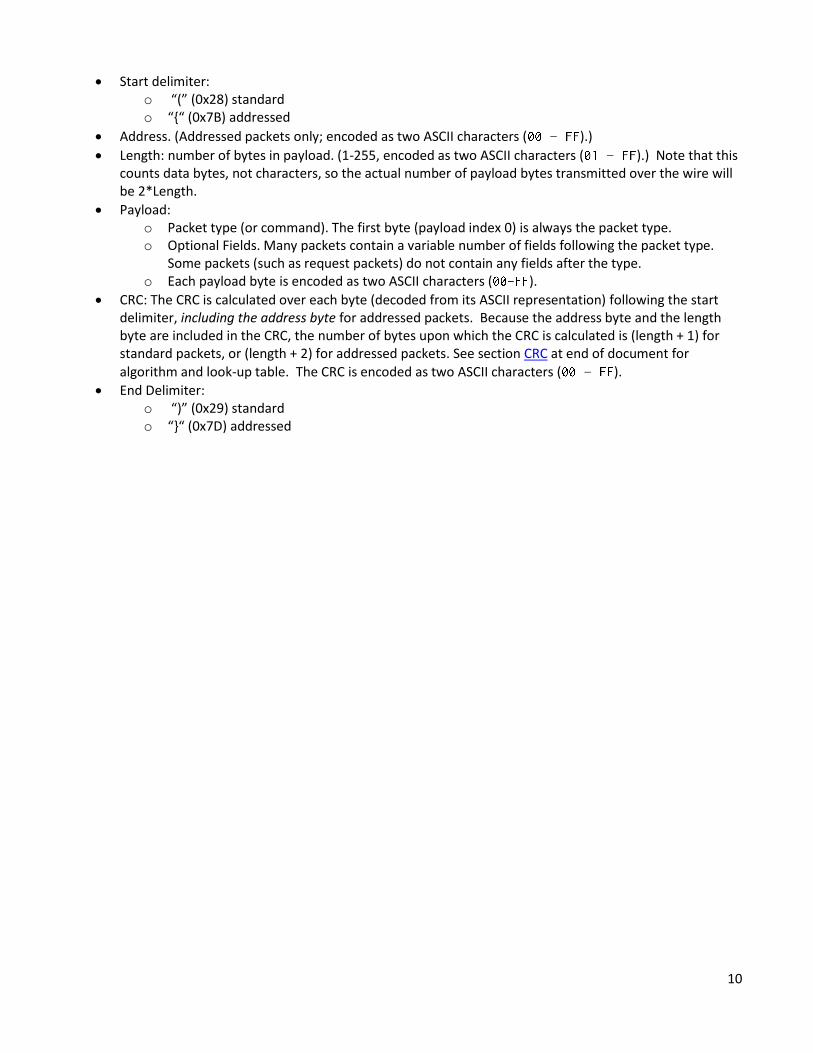
Start delimiter: o “(” (0x28) standard o “{“ (0x7B) addressed
Address. (Addressed packets only; encoded as two ASCII characters ( – ).)
Length: number of bytes in payload. (1-255, encoded as two ASCII characters ( – ).) Note that this counts data bytes, not characters, so the actual number of payload bytes transmitted over the wire will be 2*Length.
Payload: o Packet type (or command). The first byte (payload index 0) is always the packet type. o Optional Fields. Many packets contain a variable number of fields following the packet type.
Some packets (such as request packets) do not contain any fields after the type. o Each payload byte is encoded as two ASCII characters ( ).
CRC: The CRC is calculated over each byte (decoded from its ASCII representation) following the start delimiter, including the address byte for addressed packets. Because the address byte and the length byte are included in the CRC, the number of bytes upon which the CRC is calculated is (length + 1) for standard packets, or (length + 2) for addressed packets. See section CRC at end of document for algorithm and look-up table. The CRC is encoded as two ASCII characters ( – ).
End Delimiter: o “)” (0x29) standard o “}“ (0x7D) addressed

11
4 Basic Packet Behavior Upon receiving a packet with a valid CRC, the actuator will respond to the packet. All packets will yield a response packet: request packets will respond with the requested packet type, all other packets will trigger an Acknowledgement Packet. When sending command packets to the actuator, your software should always verify that a response has been received from the actuator before sending the next command. The actuator will send a response packet within 50ms of receiving a valid packet (typically much faster). If the actuator does not respond to a packet, you should assume the actuator has not received the command and should resend the command until a response is received. Actuators will never send out packets except in response to valid received packets.
If an invalid CRC is received, or a closing delimiter is not received on a packet, the packet will not be handled. The actuator will increment a counter tracking the number of consecutive damaged packets. When the number of consecutive damaged packets meets the configured limit, the system will trigger a serial fault. Upon receiving a packet with a correct CRC, the damaged packet counter will revert to 0. The behavior when a fault is triggered is specified in the Fault Behavior Packet.
All units will respond to standard packets (with “<”/“>” delimiters). Standard packets will only yield standard packets in response.
Units will only respond to addressed packets (with “[“/”]” delimiters and unit address field) with a matching address or broadcast address (0)*. Units responding to addressed packets, including broadcast packets, will respond with their own address in the return packet.
*Note: To avoid packet collisions, broadcast addressing shall only be used on busses with one actuator present (point-to-point topology). If multiple units are on a bus (multi-drop topology), actuator units must be individually addressed.
5 RS-485 and RS-232 Port Activation Actuator units configured with both RS-232 and RS-485 communication ports can use ether port at any time. The two ports run independently and process packets as they are received. Commands can be sent to either port at any time and the actuator will respond to them.
On units with an analog control input, the RS-232 or RS-485 port can be used to communicate with the actuator (e.g. for status monitoring) at any time. However, you will not be able to control the actuator over the serial connection until at least one Motor Control Packet has been sent to the unit. This will disable the analog control input. To resume analog control, power cycle the actuator or send a Reset Packet.
6 Data Types Unless otherwise noted all the packet fields will be one of the following industry standard data types. All data on the wire is in BIG ENDIAN format.
“char” – 8-bit char.
“uint8” – Unsigned 8-bit integer.
“int8” – Signed 8-bit integer.
“uint16” – Unsigned 16-bit integer.
“int16” – Signed 16-bit integer.
“uint32” – Unsigned 32-bit integer.
“int32” – Signed 32-bit integer.
“uint64” – Unsigned 64-bit integer.
“float” – 32-bit, single-precision floating point value. (IEEE 754)

12
7 Units System units are typically specified in Imperial (standard) US units. Units of length are in feet, inches, or 1/1000th of an inch (Thou or Mil).
Actuators will use the following units unless otherwise specified:
7.1 Linear Actuators o Position: thousandths of an inch (thou or mil). o Velocity: mil/minute.
o Acceleration: (mil/minute)/second.
7.2 Rotary Actuators o Position: millidegrees (thousandths of a degree). o Velocity: rotations per minute (RPM). o Acceleration: RPM/second.
8 Storage of Configuration Parameters Packet fields marked non-volatile denote system variables that are part of the unit’s saved configuration. These values will be lost on reset unless a save command is sent. These values will be reset if a load defaults command is sent.
9 System Settings When the actuator powers on, settings are loaded from non-volatile memory into RAM. When a setting is changed through a packet, the effects will take effect immediately, providing an opportunity to test changes. However, those changes will be lost unless saved to non-volatile memory by sending a Save Command.
If settings have been saved and actuator operation is not desirable, factory default settings can be loaded with a Load Defaults Command. As with other setting adjustments, loading defaults does not save values to non-volatile memory unless a save command is issued.
Loading defaults will load all* system settings. Therefore, it is advisable when adjusting parameters to be certain that changes are desirable before saving. It is recommended that the system be power cycled (Reset System Command) if a value is found to be undesirable and the previous value is unknown. Loading defaults is a last-resort option.
* The only non-volatile values not reset by loading defaults are the internal offsets used by the positioning
system. Because these offsets are performed during manufacturing and are unique to each actuator, these
values cannot be recovered once over-written. When calibrating the absolute position with a calibrate position
command or a tare command, these factory-set offsets are changed. Once a save command is issued, there is no
way to recover the values.

13
10 Actuator Movement Methods Several methods of control over actuator movement are available. Prior to issuing movement commands, the actuator motor must be turned on. If the motor is not on, commands will be ignored. If the motor is either braking or coasting when a movement command is received, braking and coasting will be disabled in order for the movement to commence.
Duty Cycle – The simplest form of motor control is triggered by sending a “+” type packet, which causes the motor to move at a fixed duty cycle (percent of full-scale power) until a different control command or a stop command is issued.
Match Value – Identical to Duty Cycle control in operation, but provides more granularity. This is triggered by sending a “^” type packet. The match value provides a fixed motor output set to a scale determined by the limit. The Maximum Match configuration parameter will limit the maximum value that will have any effect.
Position Setpoint – Uses the actuator’s internal feedback control loop to bring the actuator to a fixed position. The control loop will continue to maintain the position until a different control command or stop motor command is issued. If external forces act on the actuator, it will apply an opposing force to attempt to maintain the position. For linear actuators, both absolute and relative (to a defined zero point) setpoints can be tracked.
Velocity Setpoint – Uses the actuator’s internal feedback control loop to travel at a fixed velocity. The velocity will be maintained until a different control command or stop motor command is issued. This control method is typically only available for rotary actuators.
Position Setpoint at Fixed Velocity – Uses the actuator’s internal feedback control loop to travel at a fixed velocity until a position setpoint is reached. There are 2 main modes of Position Setpoint at Fixed Velocity:
o Simple: specify a velocity setpoint and a position setpoint in a “U” packet. The feedback control loop will track the velocity until the position setpoint is reached or passed.
o Advanced: specify a velocity setpoint, position setpoint, stop position threshold, and stop behavior in a “K” packet. Different stop behaviors may be specified as the position approaches the setpoint. The control loop may either track the position or stop at the threshold. Options for turning the motor off and braking are also available. See the packet documentation for “K” packets for more information.
11 HPU Operation Hydraulic Power Unit (HPU) actuators behave as rotary actuators. Velocity commands are used to control pump speed. For HPU speed control, it is suggested to use the 0xB6 packet, rather than the ‘W’ packet, as the former uses RPM instead of degrees per second and thus allows setting much higher motor speeds. Unless otherwise noted in the documentation for your specific unit, the forward direction (positive velocity) is the correct direction for pump operation. For HPU displacement commands (i.e. moving a fixed amount of fluid at a time), the setpoint position commands can be used. Most HPU units can only control position to the nearest whole revolution. Position setpoints which are a multiple of 360° therefore must be used for proper operation. It is suggested to set the unit’s stop behavior to stop control when the target position is reached. The unit’s position control system is based on an internal degree counter. If a large number of revolutions are accumulated, this number will overflow. This is only a problem in position control mode; velocity control is unaffected. The suggested workaround is to send the following sequence of commands if the application is expected to require a large number of revolutions: power off motor, reset rotary counters, power on motor, send position command.
Actual flow and displacement for a given speed and number of rotations can be determined based on the actual pump displacement, which will be specified in the documentation provided with your specific HPU.

14
12 System Parameter and Packet Lookup Table Packets are used to configure and control the actuator. The following table displays the relevant packet type for setting parameters or issuing commands.
Configuration Parameter Packet Type
Absolute Position S (Linear), S (Rotary)
Absolute Position Setpoint S (Linear), S (Rotary)
Baud Rate B
Board Current Limit I
Board Current Limit Reduction Percentage I
Brake Status 0x86, P (Linear), P (Rotary), X
Calibrated Position C (Linear), C (Rotary)
CAN Bus 0xB8, 0xBA
Communication Address Y
Communication Faults F
Communication Faults History N
Current P (Linear), P (Rotary)
Derivative Maximum Value – Position M (Linear), M (Rotary)
Derivative Maximum Value – Velocity D (Linear), D (Rotary)
Derivative Gain – Position M (Linear), M (Rotary)
Derivative Gain – Velocity D (Linear), D (Rotary)
Duty Cycle +
Endpoints M (Linear), M (Rotary)
Failsafe Enable 0x92
Failsafe Timeout 0x92
Failsafe Position 0x92
Failsafe Time Remaining 0x94
Faults F, N
Feed-forward control 0xA6 (Linear), 0xA6 (Rotary)
Gain Scheduling 0xAB (Linear), 0xAB (Rotary)
Hardware Brake Status 0x86, P (Linear), P (Rotary), X
High-Velocity Over-Sampling Samples. E (Linear), E (Rotary)
Integral Gain – Position M (Linear), M (Rotary)
Integral Gain – Velocity D (Linear), D (Rotary)
Integrator Maximum Value – Position M (Linear), M (Rotary)

15
Integrator Maximum Value - Velocity D (Linear), D (Rotary)
Limit M (Linear), M (Rotary)
Linear Velocity P (Linear), P (Rotary)
Low-Velocity Over-Sampling Samples E (Linear), E (Rotary)
Match Value (PWM) ^
Maximum Match Value M (Linear), M (Rotary)
Maximum Voltage 0x82
Model Identifier A
Motion Profile Configuration 0x9A (Linear), 0x9A (Rotary)
Motor Controller Faults F
Motor Controller Faults History N
Motor Current Limit I
Motor Direction P (Linear), P (Rotary)
Motor Revolutions P (Rotary)
Motor State P (Linear), P (Rotary), X
Motor Velocity P (Linear), P (Rotary)
Name 0xBC
Off-Fault Behavior O
On-Fault Behavior O
Over-Sampling Velocity Threshold E (Linear), E (Rotary)
Over Voltage Protection Enable 0x82
PID-Scale Position D (Linear), D (Rotary)
PID-Scale Velocity D (Linear), D (Rotary)
Position Absolute P (Linear), P (Rotary)
Position-Control Target Velocity D (Linear), D (Rotary)
Position Feed-Forward Enable E (Linear), E (Rotary)
Position Feed-Forward Velocity Threshold E (Linear), E (Rotary)
Position Integrator Maximum Value E (Linear), E (Rotary)
Position Low M (Linear), M (Rotary)
Position High M (Linear), M (Rotary)
Position Sensor Faults F
Position Sensor Faults History N
Position Setpoint at Fixed Velocity U (Linear), U (Rotary), K (Linear), U (Rotary)
Position Setpoint at Fixed Velocity U (Linear), U (Rotary), K (Linear), U (Rotary)

16
Position Setpoint Stop Behavior D (Linear), D (Rotary)
Position Setpoint Threshold D (Linear), D (Rotary)
Power Supply Type M (Linear), M (Rotary)
Proportional Gain – Position M (Linear), M (Rotary)
Proportional Gain – Velocity D (Linear), D (Rotary)
Relative Position Setpoint R
Relative Zero Location Z
RS485 Onboard Termination Enable 0x84
RS485 Onboard Termination Port Number 0x84
Running Average Samples E (Linear), E (Rotary)
Scaled Position 0x90
Scaled Position Setpoint 0x88
Shaft Velocity P (Rotary)
Stall Detection 0xA8(Linear), 0xA8 (Rotary)
Temperature Sensors P (Linear), P (Rotary), 0xA2
Temperature Faults F
Temperature Faults History N
Total Degrees (Rotary) P (Rotary)
Valve High Position 0x80
Valve Low Position 0x80
Velocity H (Linear), H (Rotary)
Velocity Setpoint W (Linear), W (Rotary), 0xB6 (Linear), 0xB6 (Rotary)
Version, Firmware 0x96, ?
Voltage P (Linear), P (Rotary)

17
Command Packet Type(s)
Acknowledge A
Calibrate Position C (Linear), C (Rotary),
Calibrate Current 0xAA
Clear Offsets -
In-System-Programming Activation ~
Load Factory Defaults @
Position Setpoint U (Linear), U (Rotary), K (Linear), K (Rotary),
S (Linear), S (Rotary)
Position Setpoint at Fixed Velocity U (Linear), U (Rotary), K (Linear), K (Rotary)
Relative Position Setpoint R
Reset Faults !
Reset Rotary Counters <
Reset System (Reboot) =
Reverse Direction &
Set Absolute Position Setpoint S (Linear), S (Rotary)
Set Duty Cycle +
Set Match Value ^
Set Scaled Position Setpoint 0x88
Set Velocity Setpoint W (Linear), W (Rotary)
Save Configuration to EEPROM $
Tare #
Toggle Motor X
Turn Motor On/Off X

18
13 Packet Specifications
14 Configuration Packets
14.1 Linear Actuators - Absolute Position Setpoint Packet ‘S’
14.1.1 Set Packet Type ‘S’ (0x53)
14.1.2 Request type ‘s’ (0x73)
14.1.3 Volatility All values are volatile and will change according to conditions.
14.1.4 Function If the motor is on, the control loop will be configured to move the actuator to the specified position. The characteristics of the movement are determined by the control loop gains, control loop scales, and sampling settings. The actuator will maintain this position and attempt to maintain the position if outside forces are exerted, until the motor is turned off or a different setpoint command is received. Action will take effect immediately if the motor is on. Command must be issued when the motor is on or the values will be lost.
14.1.5 Payload Length 5
14.1.6 Payload Structure
14.1.7 Field Descriptions
14.1.7.1 Packet Type The byte specifying the command: ‘S’ (0x53)
14.1.7.2 Absolute Position Setpoint Specifies the position, in mil, to which the actuator will travel upon receiving the command.
Linear – Absolute Position Setpoint Configuration
Payload Index
0 1:4
Data Type
char int32
Field Packet Type: ‘S’
Absolute Position Setpoint

19
14.2 Rotary Actuators - Absolute Position Setpoint Packet ‘S’
14.2.1 Set Packet Type ‘S’ (0x53)
14.2.2 Request type ‘s’ (0x73)
14.2.3 Volatility All values are volatile and will change according to conditions.
14.2.4 Function If the motor is on, the control loop will be configured to move the actuator to the set position. The characteristics of the movement are determined by the control loop gains, control loop scales, and sampling settings. The actuator will maintain this position and attempt to maintain the position if outside forces are exerted, until the motor is turned off or a different setpoint command is received. Action will take effect immediately if the motor is on. Command must be issued when the motor is on or the values will be lost.
14.2.5 Payload Length 5
14.2.6 Payload Structure
14.2.7 Field Descriptions
14.2.7.1 Packet Type The byte specifying the command: ‘S’
14.2.7.2 Absolute Position Setpoint Specifies the position, in millidegrees, to which the actuator will travel upon receiving the command.
Rotary - Absolute Position Setpoint Configuration
Payload Index
0 1:4
Data Type
char int32
Field Packet Type: ‘S’
Absolute Position Setpoint

20
14.3 Baud Rate Configuration Packet ‘B’
14.3.1 Set Packet Type ‘B’ (0x42)
14.3.2 Request Type ‘b’ (0x62)
14.3.3 Volatility All values in this packet are saved when a “Save to EEPROM” packet is sent. Otherwise, all values will be restored to their previous values upon the next power cycle
14.3.4 Function Sets the baud rate that that actuator will use to communicate over serial. The baud rate will change immediately upon receiving a valid baud rate packet. This allows you to verify that you can communicate with the actuator at the updated baud rate. The new baud rate will only become permanent if a save packet is sent. Otherwise, the actuator will revert to the previously saved baud rate on the next power cycle.
14.3.5 Payload Length 5
14.3.6 Payload Structure
14.3.7 Field Descriptions
14.3.7.1 Packet Type The byte indicating the packet type: ‘B’ (0x42)
14.3.7.2 Baud Rate Valid baud rates: 300 - 1000000.
Baud Rate Configuration
Payload Index
0 1:4
Data Type
char uint32
(Non-Volatile)
Field Packet Type: ‘B’ Baud rate

21
14.4 Communication Address Configuration Packet ‘Y’
14.4.1 Set Packet type ‘Y’ (0x59)
14.4.2 Request type ‘y’ (0x79)
14.4.3 Volatility All values in this packet are saved when a “Save to EEPROM” packet is sent. Otherwise, all values will be restored to their previous values upon the next power cycle.
14.4.4 Function Sets the communication address for the unit. In a point-to-point topology, this can be set by using non-addressable packets (‘<’ and ‘>’) or with addressable packets addressed to either 0 (broadcast) or the unit’s current address. Subsequent packets must be addressed using the new address. In a multi-drop bus, this packet must be addressed to the unit’s current address. Technically, a broadcast may be used, though all actuators on the bus will be configured with the new address.
14.4.5 Payload Length 2
14.4.6 Payload Structure
14.4.7 Field Descriptions
14.4.7.1 Packet Type The byte indicating the packet type: “Y” (0x59)
14.4.7.2 Communication Address Assigns the communication address for the unit. Once assigned, the unit will ignore any packets unless the address field in the packet matches the unit’s communication address, or broadcast address (0). Valid range is 1 to 255 (0 is reserved for broadcasts).
Communication Address Configuration
Payload Index
0 1
Data Type
Char uint8
(Non-Volatile)
Field Packet Type: ‘Y’
Communications Address

22
14.5 Current Limits Configuration Packet ‘I’
14.5.1 Set Packet Type ‘I’ (0x49)
14.5.2 Request Type ‘i’ (0x69)
14.5.3 Volatility All values in this packet are saved when a “Save to EEPROM” packet is sent. Otherwise, all values will be restored to their previous values upon the next power cycle
14.5.4 Function Sets the current limit parameters for the board and motor. The board current limit sets the board current level at which power-reduction measures are taken. The output will be reduced by the percentage specified for current reduction. The current will slowly rise until the original limit is in place or until the limit is reached again. These measures are high-level and will result in oscillations of the actuator output if the load is not reduced. The behavior of the motor current limit depends on the actuator: for series 4000 actuators, motor current behaves in a similar manner to board current. For 2000 and 3500 series units, motor current sets an analog limit at the motor controller; output will be limited, but oscillations will not occur.
14.5.5 Payload Length 8
14.5.6 Payload Structure
14.5.7 Field Descriptions
14.5.7.1 Packet Type The byte indicating the packet type: ‘I’ (0x49)
14.5.7.2 Board Current Limit Sets the board current limit (in milliamps). This is the limit above which power-reduction measures are taken to reduce power draw.
14.5.7.3 Board Current Limit Reduction Percentage Acceptable values: 0-100 (percent). Sets the amount by which the motor output will be reduced when the board current limit is reached.
14.5.7.4 Motor Current Limit Sets the motor control DAC value, setting a maximum motor current draw. Value is in milliamps.
Current Limits Configuration
Payload Index
0 1:4 5 6:7
Data Type
char uint32
(Non-Volatile)
uint8
(Non-Volatile)
uint16
(Non-Volatile)
Field Packet Type: ‘I’
Board Current Limit Board Current Limit Reduction Percentage.
Motor Current Limit.

23
14.6 Linear Actuators - Failsafe Configuration Packet 0x92
14.6.1 Set Packet Type 0x92
14.6.2 Request Type 0x93
14.6.3 Volatility All values in this packet are saved when a “Save to EEPROM” packet is sent. Otherwise, all values will be restored to their previous values upon the next power cycle
14.6.4 Function This packet is used to enable and configure the failsafe mode. When in failsafe mode, the actuator will move to a specified position if no System Info packets are received within a certain amount of time.
14.6.5 Payload Length 10
14.6.6 Payload Structure
14.6.7 Field Descriptions
14.6.7.1 Packet Type The byte indicating the packet type: 0x92(set), 0x93(request)
14.6.7.2 Failsafe Enable Bit 0: 0 – Disable Failsafe Mode 1 – Enable Failsafe Mode Bit 1: 0 – Do not copy Failsafe Configuration to Global Configuration 1 – Copy Failsafe Configuration to Global Configuration
If this is set, the failsafe configuration will be copied to the global configuration file. If a “Save Configuration to EEPROM” packet is subsequently issued, the specified failsafe configuration will be automatically enabled every time the actuator is powered on. This configuration will persist until the failsafe mode is manually disabled and another “Save Configuration to EEPROM” command is issued. In packets returned from the actuator, this bit will be set if the currently active failsafe configuration matches the failsafe configuration in the global configuration file.
Linear – Failsafe Configuration
Payload Index
0 1 2:5 6:9
Data Type
Char uint8
(Non-Volatile)
uint32
(Non-Volatile)
int32
(Non-Volatile)
Field Packet Type: 0x92
Failsafe Enable Timeout Failsafe Position

24
14.6.7.3 Timeout Specifies, in milliseconds, the failsafe timeout. When failsafe mode is enabled, if this amount of time elapses without the actuator receiving a valid packet, the actuator will move to the failsafe position. The timeout is accurate to within 100ms. Timeout values greater than (2^32 – 200) are undefined.
14.6.7.4 Failsafe Position Specifies the position to which the actuator will move, in mil, after the timeout has expired.

25
14.7 Rotary Actuators - Failsafe Configuration Packet 0x92
14.7.1 Set Packet Type 0x92
14.7.2 Request Type 0x93
14.7.3 Volatility All values in this packet are saved when a “Save to EEPROM” packet is sent. Otherwise, all values will be restored to their previous values upon the next power cycle.
14.7.4 Function This packet is used to enable and configure the failsafe mode. When in failsafe mode, the actuator will move to a specified position if no System Info request packets are received within a certain amount of time.
14.7.5 Payload Length 10
14.7.6 Payload Structure
14.7.7 Field Descriptions
14.7.7.1 Packet Type The byte indicating the packet type: 0x92(set), 0x93(request)
14.7.7.2 Failsafe Enable Bit 0: 0 – Disable Failsafe Mode 1 – Enable Failsafe Mode Bit 1: 0 – Do not copy Failsafe Configuration to Global Configuration 1 – Copy Failsafe Configuration to Global Configuration
If this is set, the failsafe configuration will be copied to the global configuration file. If a “Save Configuration to EEPROM” packet is subsequently issued, the specified failsafe configuration will be automatically enabled every time the actuator is powered on. This configuration will persist until the failsafe mode is manually disabled and another “Save Configuration to EEPROM” command is issued. In packets returned from the actuator, this bit will be set if the currently active failsafe configuration matches the failsafe configuration in the global configuration file.
Rotary – Failsafe Configuration
Payload Index
0 1 2:5 6:9
Data Type
char uint8
(Non-Volatile)
uint32
(Non-Volatile)
int32
(Non-Volatile)
Field Packet Type: 0x92
Failsafe Enable Timeout Failsafe Position

26
14.7.7.3 Timeout Specifies the failsafe timeout, in milliseconds. When failsafe mode is enabled, if the timeout time elapses without the actuator receiving a valid packet, the actuator will move to the failsafe position. The timeout is accurate to within 100ms. Timeout values greater than (232 – 200) are undefined.
14.7.7.4 Failsafe Position Specifies the position, in millidegrees, to which the actuator will move after the timeout has expired.

27
14.8 Fault Behavior Configuration Packet ‘O’
14.8.1 Set Packet Type ‘O’ (0x4F)
14.8.2 Request Type ‘o’ (0x6F)
14.8.3 Volatility All values in this packet are saved when a “Save to EEPROM” packet is sent. Otherwise, all values will be restored to their previous values upon the next power cycle
14.8.4 Function Configures the behavior of the actuator when faults occur.
14.8.5 Payload Length 3
14.8.6 Payload Structure
14.8.7 Field Descriptions
14.8.7.1 Packet Type The byte indicating the packet type: ‘O’ (0x4F)
14.8.7.2 On-Fault Behavior Sets the actuator behavior when a fault occurs:
0 – Turn off motor. 1 – Brake motor. 2 – Coast motor. 3 – Continue operation and report fault.
14.8.7.3 Reserved As of actuator firmware version 4.0 (released 2016-03-07), this field is not used and has no effect on actuator operation.
Fault Behavior Configuration
Payload Index
0 1 2
Data Type
Char uint8
(Non-Volatile)
uint8
(Non-Volatile)
Field Packet Type: ‘O’
On-Fault Behavior Reserved

28
14.9 Hardware Brake Configuration Packet 0x86
14.9.1 Set Packet Type 0x86
14.9.2 Request Type 0x87
14.9.3 Volatility All values are volatile and will change according to conditions.
14.9.4 Function This packet is only functional on actuators with a hardware brake installed. Issuing this command will engage or disengage the hardware brake.
14.9.5 Payload Length 2
14.9.6 Payload Structure
14.9.7 Field Descriptions
14.9.7.1 Packet Type The byte indicating the packet type: 0x86(set), 0x87(request)
14.9.7.2 Brake Status Indicates the hardware brake status. This field uses the following enumerated values: 0 – Disengage the hardware brake. If the motor is currently not tracking a setpoint, this will turn the motor on and place it into the coast state. In received packet, indicates the hardware brake is disengaged. 1 – Engage the hardware brake. If the motor is currently tracking a setpoint, the motor will stop tracking the current setpoint before engaging the brake. In received packet, indicates the hardware brake is engaged.
Hardware Brake Configuration
Payload Index
0 1
Data Type
char uint8
Field Packet Type: 0x86
Brake Status

29
14.10 Motor Control Configuration Packet ‘X’
14.10.1 Set Packet Type ‘X’ (0x58)
14.10.2 Request type ‘x’ (0x78)
14.10.3 Volatility All values are volatile and will change according to conditions.
14.10.4 Function The motor control packet is used to toggle motor states. The motor must be turned on before the actuator will respond to any movement commands.
14.10.5 Payload Length 2
14.10.6 Payload Structure
14.10.7 Field Descriptions
14.10.7.1 Packet Type The byte specifying the command: ‘X’ (0x58)
14.10.7.2 Motor State Packets sent to actuator shall use the following enumerated values:
0 – Turn Off 1 – Turn On (brake off, coast off) 2 – Turn On and Brake 3 – Turn On and Coast
Packets received from the actuator contain additional information regarding hardware braking (certain models are enabled for hardware braking). Below are the designations sent out from the actuator: Bits 0-2: 000 – Motor is Off. 001 – Motor is On. 010 – Motor is On and Braking. 011 – Motor is On and Coasting. Bit 4 – Reserved Bit 5 – Reserved Bit 6: 0 – Hardware Brake is Disengaged.
Motor Control Configuration
Payload Index
0 1
Data Type
char uint8
Field Packet Type: ‘X’
Motor State

30
1 – Hardware Brake is Engaged. Bit 7: 0 – Unit does not have hardware brake. 1 – Unit has hardware brake.

31
14.11 Overvoltage Protection Configuration Packet 0x82
14.11.1 Set Packet Type 0x82
14.11.2 Request Type 0x83
14.11.3 Volatility All values in this packet are saved when a “Save to EEPROM” packet is sent. Otherwise, all values will be restored to their previous values upon the next power cycle
14.11.4 Function (if this feature is equipped) Sets a maximum voltage limit for the actuator. Above this limit, the actuator will switch into braking mode. This is useful to prevent damage to the actuator if it is backdriven.
14.11.5 Payload Length 6
14.11.6 Payload Structure
14.11.7 Field Descriptions
14.11.7.1 Packet Type The byte indicating the packet type: 0x82(set), 0x83 (request)
14.11.7.2 Overvoltage protection enable 0 – Disabled. 1 – Enabled.
14.11.7.3 Maximum Voltage Specifies the voltage, in mV, over which the actuator will automatically brake.
Overvoltage Protection Configuration
Payload Index
0 1 2:5
Data Type
char bool
(Non-Volatile)
uint32
(Non-Volatile)
Field Packet Type: 0x82
Overvoltage protection enable Maximum Voltage

32
14.12 Linear Actuators - Position Sampling Configuration Packet ‘E’
14.12.1 Set Packet Type ‘E’ (0x45)
14.12.2 Request Type ‘e’ (0x65)
14.12.3 Volatility All values in this packet are saved when a “Save to EEPROM” packet is sent. Otherwise, all values will be restored to their previous values upon the next power cycle
14.12.4 Function This packet configures various parameters of the actuator’s positioning system. Generally, this is not changed from factory values. Changing values will have an effect on control reactivity, stability, and general tuning of the feedback control structure. It is advisable to re-tune the actuator if any of these values are modified.
14.12.5 Payload Length 15
14.12.6 Payload Structure
14.12.7 Field Descriptions
14.12.7.1 Packet Type The byte indicating the packet type: ‘E’ (0x45)
14.12.7.2 Low-Velocity Over-Sampling Samples The number of samples to take when velocity is below the velocity threshold (see 3rd parameter in packet). Valid range: 1-500. Use value 1 to perform no over-sampling.
14.12.7.3 High-Velocity Over-Sampling Samples The number of samples to take when velocity is above the velocity threshold (see 3rd parameter in packet). Valid range: 1-500. Use value 1 to perform no over-sampling.
Linear – Position Sampling Configuration
Payload Index
0 1:2 3:4 5:8 9 10 11:14
Data Type
Char uint16
(Non-Volatile)
uint16
(Non-Volatile)
uint32
(Non-Volatile)
uint8
(Non-Volatile)
bool
(Non-Volatile)
uint32
(Non-Volatile)
Field Packet Type: ‘E’
Low-Velocity Over-Sampling Samples.
High-Velocity Over-Sampling Samples.
Over-Sampling Velocity Threshold.
Running-Average Samples.
Unused/ No Effect Unused/ No Effect

33
14.12.7.4 Over-Sampling Velocity Threshold Determines whether to use Low-Velocity samples or High-Velocity samples for oversampling. Using a lower value for high-velocity increases the system responsiveness at higher speeds.
14.12.7.5 Running-Average Samples Determines the window size of the running average function used to generate actuator position. Maximum number: 64
14.12.7.6 Unused The value has no effect on the behavior of the System.
14.12.7.7 Unused The value has no effect on the behavior of the System.

34
14.13 Rotary Actuators - Position Sampling Configuration Packet ‘E’
14.13.1 Set Packet Type ‘E’ (0x45)
14.13.2 Request Type ‘e’ (0x65)
14.13.3 Volatility All values in this packet are saved when a “Save to EEPROM” packet is sent. Otherwise, all values will be restored to their previous values upon the next power cycle
14.13.4 Function This packet configures various parameters of the actuator’s positioning system. Generally, this is not changed from factory values. Changing values will have an effect on control reactivity, stability, and general tuning of the feedback control structure. It is advisable to re-tune the actuator if any of these values are modified.
14.13.5 Payload Length 15
14.13.6 Payload Structure
14.13.7 Field Descriptions
14.13.7.1 Packet Type The byte indicating the packet type: ‘E’ (0x45)
14.13.7.2 Low-Velocity Over-Sampling Samples The number of samples to take when velocity is below the velocity threshold (see 3rd parameter in packet). Valid range: 1-500. Use value 1 to perform no over-sampling.
14.13.7.3 High-Velocity Over-Sampling Samples The number of samples to take when velocity is above the velocity threshold (see 3rd parameter in packet). Valid range: 1-500. Use value 1 to perform no over-sampling.
Rotary - Position Sampling Configuration
Payload Index
0 1:2 3:4 5:8 9 10 11:14
Data Type
Char uint16
(Non-Volatile)
uint16
(Non-Volatile)
uint32
(Non-Volatile)
uint8
(Non-Volatile)
bool
(Non-Volatile)
uint32
(Non-Volatile)
Field Packet Type: ‘E’
Low-Velocity Over-Sampling Samples.
High-Velocity Over-Sampling Samples.
Over-Sampling Velocity Threshold.
Running-Average Samples.
Unused/ No Effect
Unused/ No effect

35
14.13.7.4 Over-Sampling Velocity Threshold Determines whether to use Low-Velocity samples or High-Velocity samples for oversampling. Using a lower value for high-velocity increases the system responsiveness at higher speeds.
14.13.7.5 Running-Average Samples Determines the window size of the running average function used to generate actuator position. Maximum number: 64
14.13.7.6 Unused The value has no effect on the behavior of the System.
14.13.7.7 Unused The value has no effect on the behavior of the System.

36
14.14 Linear Actuators - Position Setpoint at Fixed Velocity Configuration Packet ‘U’
14.14.1 Set Packet Type ‘U’ (0x55)
14.14.2 Request type ‘u’ (0x75)
14.14.3 Volatility All values are volatile and will change according to conditions.
14.14.4 Function This command causes the actuator to move to an absolute position setpoint at a fixed velocity. This allows overriding the system velocity target for position control. This packet is the simplified method of sending a position setpoint at fixed velocity command. The extended version of the packet (‘K’) contains an additional threshold parameter, as well as allowing the endpoint behavior to be specified. For this packet, the threshold is assumed to be 0, and the endpoint behavior is set to 1 (Stop Tracking). See documentation on the K packet for more information. Action will take effect immediately if the motor is on. Command must be issued when the motor is on, or the values will be lost.
14.14.5 Payload Length 9
14.14.6 Payload Structure
14.14.7 Field Descriptions
14.14.7.1 Packet Type The byte specifying the command: ‘U’ (0x55)
14.14.7.2 Velocity Velocity at which the shaft will travel, in mil per minute, until reaching the position setpoint.
14.14.7.3 Position Setpoint The absolute position to which the shaft will travel, in mil.
Linear – Position Setpoint at Fixed Velocity Configuration
Payload Index
0 1:4 5:8
Data Type
char uint32
int32
Field Packet Type: ‘U’
Velocity Position Setpoint

37
14.15 Rotary Actuators - Position Setpoint at Fixed Velocity Configuration Packet ‘U’
14.15.1 Set Packet Type ‘U’ (0x55)
14.15.2 Request type ‘u’ (0x75)
14.15.3 Volatility All values are volatile and will change according to conditions.
14.15.4 Function This command causes the actuator to move to an absolute position setpoint at a fixed velocity. This allows overriding the system velocity target for position control. This packet is the simplified method of sending a position setpoint at fixed velocity command. The extended version of the packet (‘K’) contains an additional threshold parameter, as well as allowing the endpoint behavior to be specified. For this packet, the threshold is assumed to be 0, and the endpoint behavior is set to 1 (Stop Tracking). See documentation on the K packet for more information. Action will take effect immediately if the motor is on. Command must be issued when the motor is on, or the values will be lost.
14.15.5 Payload Length 9
14.15.6 Payload Structure
14.15.7 Field Descriptions
14.15.7.1 Packet Type The byte specifying the command: ‘U’ (0x55)
14.15.7.2 Velocity Velocity at which the shaft will rotate until reaching the position setpoint. The units are in milli-RPM (1/1000 rotation per minute).
14.15.7.3 Position Setpoint The absolute position to which the shaft will rotate, in millidegrees. This value may be negative.
Rotary - Position Setpoint at Fixed Velocity Configuration
Payload Index
0 1:4 5:8
Data Type
char uint32
int32
Field Packet Type: ‘U’
Velocity Position Setpoint
38
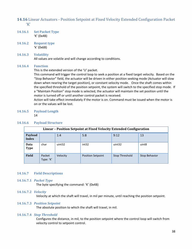
14.16 Linear Actuators - Position Setpoint at Fixed Velocity Extended Configuration Packet ‘K’
14.16.1 Set Packet Type ‘K’ (0x4B)
14.16.2 Request type ‘k’ (0x6B)
14.16.3 Volatility All values are volatile and will change according to conditions.
14.16.4 Function This is the extended version of the ‘U’ packet. This command will trigger the control loop to seek a position at a fixed target velocity. Based on the “Stop Behavior” field, the actuator will be driven in either position seeking mode (Actuator will slow down when nearing the target position), or constant velocity mode. Once the shaft comes within the specified threshold of the position setpoint, the system will switch to the specified stop mode. If a “Maintain Position” stop mode is selected, the actuator will maintain the set position until the motor is turned off or until another control packet is received. Action will take effect immediately if the motor is on. Command must be issued when the motor is on or the values will be lost.
14.16.5 Payload Length 14
14.16.6 Payload Structure
14.16.7 Field Descriptions
14.16.7.1 Packet Type The byte specifying the command: ‘K’ (0x4B)
14.16.7.2 Velocity Velocity at which the shaft will travel, in mil per minute, until reaching the position setpoint.
14.16.7.3 Position Setpoint The absolute position to which the shaft will travel, in mil.
14.16.7.4 Stop Threshold Configures the distance, in mil, to the position setpoint where the control loop will switch from velocity control to setpoint control.
Linear – Position Setpoint at Fixed Velocity Extended Configuration
Payload Index
1:4 5:8 9:12 13
Data Type
char uint32
int32 uint32 uint8
Field Packet Type: ‘K’
Velocity Position Setpoint Stop Threshold Stop Behavior

39
Configuring value zero will cause the control loop to seek velocity until the position setpoint is reached (this behavior is the same as using the simple form of the command) and then stop the motor (overshoot will be dependent on many factors including control loop run frequency, velocity setpoint, etc.)
14.16.7.5 Stop Behavior Specifies the behavior upon reaching the threshold or position setpoint. Use the following enumerated values:
0 – Seek position with specified maximum velocity. Maintain position when reached. 1 – Seek position with specified maximum velocity. Stop control when position reached. 2 – Seek position with specified maximum velocity. Turn off motor when position is reached. 3 – Seek position with specified maximum velocity. Brake when position is reached. 4 – Drive actuator at specified velocity. Stop control when position is reached or passed* 5 – Drive actuator at specified velocity. Turn off motor when position is reached or passed* 6 – Drive actuator at specified velocity. Brake motor when position is reached or passed* 7 – Seek position with specified maximum velocity. Apply hardware brake when position is reached. 8 – Drive actuator at specified velocity. Apply hardware brake when position is reached or passed* All other values are undefined and should not be used.
*Actuator may overshoot target position due to mechanical inertia.

40
14.17 Rotary Actuators - Position Setpoint at Fixed Velocity Extended Configuration Packet ‘K’
14.17.1 Set Packet Type ‘K’ (0x4B)
14.17.2 Request type ‘k’ (0x6B)
14.17.3 Volatility All values are volatile and will change according to conditions.
14.17.4 Function This is the extended version of the ‘U’ packet. This command will trigger the control loop to seek a position at a fixed target velocity. Based on the “Stop Behavior” field, the actuator will be driven in either position seeking mode (Actuator will slow down when nearing the target position), or constant velocity mode. Once the shaft comes within the specified threshold of the position setpoint, the system will switch to the specified stop mode. If a “Maintain Position” stop mode is selected, the actuator will maintain the set position until the motor is turned off or until another control packet is received. Action will take effect immediately if the motor is on. Command must be issued when the motor is on or the values will be lost.
14.17.5 Payload Length 14
14.17.6 Payload Structure
14.17.7 Field Descriptions
14.17.7.1 Packet Type The byte specifying the command: ‘K’ (0x4B)
14.17.7.2 Velocity Velocity at which the shaft will rotate until reaching the position setpoint. The units are in milli-RPM (1/1000 rotation per minute).
14.17.7.3 Position Setpoint The absolute position to which the shaft will travel, in millidegrees.
Rotary - Position Setpoint at Fixed Velocity Extended Configuration
Payload Index
1:4 5:8 9:12 13
Data Type
Char uint32
int32 uint32 uint8
Field Packet Type: ‘K’
Velocity Position Setpoint Stop Threshold Stop Behavior

41
14.17.7.4 Stop Threshold Configures the distance, in millidegrees, to the position setpoint where the control loop will switch from velocity control to setpoint control. Configuring value zero will cause the control loop to seek velocity until the position setpoint is reached (this behavior is the same as using the simple form of the command) and then stop the motor (overshoot will be dependent on many factors including control loop run frequency, velocity setpoint, etc.)
14.17.7.5 Stop Behavior Specifies the behavior upon reaching the threshold or position setpoint. Use the following enumerated values:
0 – Seek position with specified maximum velocity. Maintain position when reached. 1 – Seek position with specified maximum velocity. Stop control when position reached. 2 – Seek position with specified maximum velocity. Turn off motor when position is reached. 3 – Seek position with specified maximum velocity. Brake when position is reached. 4 – Drive actuator at specified velocity. Stop control when position is reached or passed* 5 – Drive actuator at specified velocity. Turn off motor when position is reached or passed* 6 – Drive actuator at specified velocity. Brake motor when position is reached or passed* 7 – Seek position with specified maximum velocity. Apply hardware brake when position is reached. 8 – Drive actuator at specified velocity. Apply hardware brake when position is reached or passed* All other values are undefined and should not be used.
*Actuator may overshoot target position due to mechanical inertia.

42
14.18 Linear Actuators – Relative Position Setpoint Packet ‘R’
14.18.1 Set Packet Type ‘R’ (0x52)
14.18.2 Request type ‘R’ (0x72)
14.18.3 Volatility All values are volatile and will change according to conditions.
14.18.4 Function Relative positioning is not supported on rotary actuators. If the motor is on, the control loop will be configured to move the actuator to the position relative to relative-zero. The characteristics of the movement are determined by the control loop gains, control loop scales, and sampling settings. The actuator will maintain this position and attempt to maintain the position if outside forces are exerted, until the motor is turned off or a different setpoint command is received. Action will take effect immediately if the motor is on. Command must be issued when the motor is on or the values will be lost.
14.18.5 Payload Length 5
14.18.6 Payload Structure
14.18.7 Field Descriptions
14.18.7.1 Packet Type The byte specifying the command: ‘R’ (0x52)
14.18.7.2 Relative Position Setpoint Specifies the position, in mil, to which the actuator will travel upon receiving the command. The position may be negative if the relative zero position is greater than position 0.
Linear – Relative Position Setpoint Configuration
Payload Index
0 1:4
Data Type
Char int32
Field Packet Type: ‘R’
Relative Position Setpoint
43
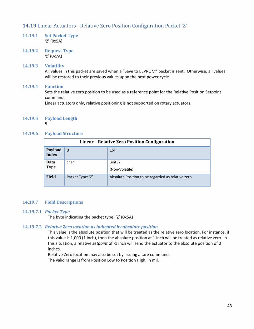
14.19 Linear Actuators - Relative Zero Position Configuration Packet ‘Z’
14.19.1 Set Packet Type ‘Z’ (0x5A)
14.19.2 Request Type ‘z’ (0x7A)
14.19.3 Volatility All values in this packet are saved when a “Save to EEPROM” packet is sent. Otherwise, all values will be restored to their previous values upon the next power cycle
14.19.4 Function Sets the relative zero position to be used as a reference point for the Relative Position Setpoint command. Linear actuators only, relative positioning is not supported on rotary actuators.
14.19.5 Payload Length 5
14.19.6 Payload Structure
14.19.7 Field Descriptions
14.19.7.1 Packet Type The byte indicating the packet type: ‘Z’ (0x5A)
14.19.7.2 Relative Zero location as indicated by absolute position This value is the absolute position that will be treated as the relative zero location. For instance, if this value is 1,000 (1 inch), then the absolute position at 1 inch will be treated as relative zero. In this situation, a relative setpoint of -1 inch will send the actuator to the absolute position of 0 inches. Relative Zero location may also be set by issuing a tare command. The valid range is from Position Low to Position High, in mil.
Linear – Relative Zero Position Configuration
Payload Index
0 1:4
Data Type
char uint32
(Non-Volatile)
Field Packet Type: ‘Z’ Absolute Position to be regarded as relative zero.

44
14.20 RS485 Termination Configuration Packet 0x84 (Actuators equipped with RS485 Only)
14.20.1 Set Packet Type 0x84
14.20.2 Request Type 0x85 Note that this request packet must include the desired port number as an additional byte after the request type. Example request packet for port 1:
14.20.3 Volatility All values in this packet are saved when a “Save to EEPROM” packet is sent. Otherwise, all values will be restored to their previous values upon the next power cycle
14.20.4 Function This command enables a built-in termination resistor of 120 ohms across the RS-485 D+ and D- lines.
14.20.5 Payload Length 3
14.20.6 Payload Structure (Firmware versions below 3.10 do not include the Port Number in their response packets)
14.20.7 Field Descriptions
14.20.7.1 Packet Type The byte indicating the packet type: 0x84 (set), 0x85 (request)
14.20.7.2 Port Number 1 – RS485 Port 1 2 – RS485 Port 2 (if equipped)
14.20.7.3 Port Termination Enable 0 – Port Termination Disabled 1 – Port Termination Enabled
RS485 Onboard Termination Configuration
Payload Index
0 1 2
Data Type
char uint8
(Non-Volatile)
bool
(Non-Volatile)
Field Packet Type: 0x84
Port Number Port Termination Enable

45
14.21 Scaled Position Setpoint Configuration Packet 0x88 (Actuators equipped with position scaling only)
14.21.1 Set Packet Type 0x88
14.21.2 Request Type 0x89
14.21.3 Volatility All values are volatile and will change according to conditions.
14.21.4 Function This packet is used to send a scaled absolute setpoint, or request the current scaled position of the actuator
14.21.5 Payload Length 5
14.21.6 Payload Structure
14.21.7 Field Descriptions
14.21.7.1 Packet Type The byte indicating the packet type: 0x88 (set), 0x89 (request)
14.21.7.2 Scaled Setpoint Sets the point to which the actuator will travel, scaled using the actuator’s internal scaling function. 0 is the center point, and -10000 to 10000 represent the extremes of travel. Input points are mapped to actuator shaft positions using a customer-specified equation.
Scaled Position Setpoint
Payload Index
0 1:4
Data Type
char int32
Field Packet Type: 0x88
Scaled Setpoint

46
14.22 Linear Actuators - System Configuration 1 Packet ’M’
14.22.1 Set Packet Type ‘M’ (0x4D)
14.22.2 Request type ‘m’ (0x6D)
14.22.3 Volatility All values in this packet are saved when a “Save to EEPROM” packet is sent. Otherwise, all values will be restored to their previous values upon the next power cycle
14.22.4 Function The first of 2 main system configuration packets, this packet deals with the basic position-control tuning parameters and hardware related parameters relevant to basic motion control.
14.22.5 Payload Length 34
14.22.6 Payload Structure
Linear – System Configuration 1 (Table 1 of 2)
Payload Index
0 1:4 5:8 9:12 13:16 17:20
Data Type
Char Float
(Non-Volatile)
float
(Non-Volatile)
float
(Non-Volatile)
float
(Non-Volatile)
float
(Non-Volatile)
Field Packet type ‘M’
Proportional Gain for position control loop
Integral Gain for position control loop
Derivative Gain for position control loop
Position Error Integrator maximum value
Derivative clamp value
Linear – System Configuration 1 (Table 2 of 2)
Payload Index
21:22 23:24 25:28 29:32 33
Data Type
uint16
(Non-Volatile)
uint16
(Non-Volatile)
int32
(Non-Volatile)
int32
(Non-Volatile)
uint8
(Non-Volatile)
Field Limit/Period Maximum Match
Position High Position Low Power Supply Type

47
14.22.7 Field Descriptions
14.22.7.1 Packet Type The byte indicating the packet type: ‘M’ (0x4D)
14.22.7.2 Proportional Gain for Position Control Loop Tunes the proportional response of the position control PID loop.
14.22.7.3 Integral Gain for Position Control Loop Tunes the integral response of the position control PID loop.
14.22.7.4 Derivative Gain for Position Control Loop Tunes the derivative response of the position control PID loop.
14.22.7.5 Position Error Integrator Maximum Value Sets an upper limit to how large the integrator can grow.
14.22.7.6 Derivative Clamp Value Sets an upper limit for the contribution of the derivative term to the overall PID system output.
14.22.7.7 Limit/Period Sets the value of the limit (period) register. This governs the PWM periodicity for the energy being supplied to the motor.
14.22.7.8 Maximum Match Sets the maximum match for the pulse-width modulation of power supplied to the motor. In effect, this governs the upper limit of the duty cycle.
14.22.7.9 Position High This indicates the upper range of actuator movement. For setpoint control, this will be the highest absolute position, in mils, to which the actuator will extend.
14.22.7.10 Position Low This indicates the lower range of actuator movement. For setpoint control, this will be the lowest absolute position, in mils, to which the actuator will retract.
14.22.7.11 Power Supply Type Used to determine current limiting factors. Use the following enumerations: 0 – Battery 1 – Power Supply

48
14.23 Rotary Actuators - System Configuration 1 Packet ’M’
14.23.1 Set Packet Type ‘M’ (0x4D)
14.23.2 Request type ‘m’ (0x6D)
14.23.3 Volatility All values in this packet are saved when a “Save to EEPROM” packet is sent. Otherwise, all values will be restored to their previous values upon the next power cycle
14.23.4 Function The first of 2 main system configuration packets, this packet deals with the basic position-control tuning parameters and hardware related parameters relevant to basic motion control.
14.23.5 Payload Length 34
14.23.6 Payload Structure
Rotary – System Configuration 1 (Table 1 of 2)
Payload Index
0 1:4 5:8 9:12 13:16 17:20
Data Type
Char Float
(Non-Volatile)
float
(Non-Volatile)
Float
(Non-Volatile)
float
(Non-Volatile)
float
(Non-Volatile)
Field Packet type ‘M’
Proportional Gain for position control loop
Integral Gain for position control loop
Derivative Gain for position control loop
Position Error Integrator maximum value
Derivative clamp value
Rotary – System Configuration 1 (Table 2 of 2)
Payload Index
21:22 23:24 25:28 29:32 33
Data Type
uint16
(Non-Volatile)
uint16
(Non-Volatile)
int32
(Non-Volatile)
int32
(Non-Volatile)
uint8
(Non-Volatile)
Field Limit/Period Maximum Match
Position High Position Low Power Supply Type

49
14.23.7 Field Descriptions
14.23.7.1 Packet Type The byte indicating the packet type: ‘M’ (0x4D)
14.23.7.2 Proportional Gain for Position Control Loop Tunes the proportional response of the position control PID loop.
14.23.7.3 Integral Gain for Position Control Loop Tunes the integral response of the position control PID loop.
14.23.7.4 Derivative Gain for Position Control Loop Tunes the derivative response of the position control PID loop.
14.23.7.5 Position Error Integrator Maximum Value Sets an upper limit to how large the position error integrator can grow.
14.23.7.6 Derivative Clamp Value Sets an upper limit for the contribution of the derivative term to the overall PID system output.
14.23.7.7 Limit/Period Sets the value of the limit (period) register. This governs the PWM periodicity on the power being supplied to the motor.
14.23.7.8 Maximum Match Sets the maximum match for the pulse-width modulation of power supplied to the motor. In effect, this governs the upper limit of the duty cycle.
14.23.7.9 Position High For actuators that use endpoints (not free spinning), this indicates the upper range of actuator rotation. For setpoint control, this will be the highest position, in millidegrees, to which the actuator will rotate.
14.23.7.10 Position Low For actuators that use endpoints (not free spinning), this indicates the lower range of actuator rotation. For setpoint control, this will be the lowest position, in millidegrees, to which the actuator will rotate.
14.23.7.11 Power Supply Type Used to determine current limiting factors. Use the following enumerations: 0 – Battery 1 – Power Supply
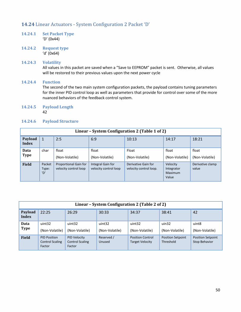
50
14.24 Linear Actuators - System Configuration 2 Packet ‘D’
14.24.1 Set Packet Type ‘D’ (0x44)
14.24.2 Request type ‘d’ (0x64)
14.24.3 Volatility All values in this packet are saved when a “Save to EEPROM” packet is sent. Otherwise, all values will be restored to their previous values upon the next power cycle
14.24.4 Function The second of the two main system configuration packets, the payload contains tuning parameters for the inner PID control loop as well as parameters that provide for control over some of the more nuanced behaviors of the feedback control system.
14.24.5 Payload Length 42
14.24.6 Payload Structure
Linear – System Configuration 2 (Table 1 of 2)
Payload Index
1 2:5 6:9 10:13 14:17 18:21
Data Type
char float
(Non-Volatile)
float
(Non-Volatile)
Float
(Non-Volatile)
float
(Non-Volatile)
float
(Non-Volatile)
Field Packet Type: 'D’
Proportional Gain for velocity control loop
Integral Gain for velocity control loop
Derivative Gain for velocity control loop.
Velocity Integrator Maximum Value
Derivative clamp value
Linear – System Configuration 2 (Table 2 of 2)
Payload Index
22:25 26:29 30:33 34:37 38:41 42
Data Type
uint32
(Non-Volatile)
uint32
(Non-Volatile)
uint32
(Non-Volatile)
uint32
(Non-Volatile)
uin32
(Non-Volatile)
uint8
(Non-Volatile)
Field PID Position Control Scaling Factor
PID Velocity Control Scaling Factor
Reserved / Unused
Position Control Target Velocity
Position Setpoint Threshold
Position Setpoint Stop Behavior

51
14.24.7 Field Descriptions
14.24.7.1 Packet Type The byte indicating the packet type: ‘D’ (0x44)
14.24.7.2 Proportional Gain for Velocity Control Loop Tunes the proportional response of the velocity control PID loop.
14.24.7.3 Integral Gain for Velocity Control Loop Tunes the integral response of the velocity control PID loop.
14.24.7.4 Derivative Gain for Velocity Control Loop Tunes the derivative response of the velocity control PID loop.
14.24.7.5 Velocity Integrator Maximum Value Sets an upper limit on how large the error integrator can grow.
14.24.7.6 Derivative Clamp Value Sets an upper limit for the contribution of the derivative term to the overall PID system output.
14.24.7.7 PID Scale Position When the actuator is issued a position setpoint, this parameter controls how sensitive the PID controller is to the position error. This is a unitless quantity which controls how quickly the position control loop will saturate at its highest value (the position control target velocity) for a given position error.
14.24.7.8 PID Scale Velocity When the actuator is issued a position or velocity setpoint, this parameter controls how sensitive the PID controller is to the velocity error. This is a unitless quantity which controls how quickly the velocity will saturate at its highest value (100% motor duty cycle) for a given velocity error.
14.24.7.9 Reserved/Unused The value has no effect on the system.
14.24.7.10 Position Target Velocity When the actuator is issued a position setpoint command, this is the maximum velocity (in milli-inches per minute) that the control loop will use before slowing down as the shaft nears the setpoint. When motion profiling is enabled, this value is also used as the speed limit for position-to-positon profiles.
14.24.7.11 Position Setpoint Threshold The position setpoint threshold is the allowable error between the position setpoint and the shaft position at which point the system will assume the setpoint has been reached and will then act according to the setpoint stop behavior (see field below). This field is in milli-inches.
14.24.7.12 Setpoint stop behavior Indicates actuator behavior once the shaft reaches the setpoint (less the setpoint threshold). Use the following enumerations: 0 – Continue to seek position until the motor is turned off or a new command is issued. 1 – Stop tracking position when the setpoint is reached. 2 – Stop motor when setpoint is reached. 3 – Electronic brake when setpoint is reached. 4 – Stop motor and hardware brake when position is reached.

52
14.25 Rotary Actuators - System Configuration 2 Packet ‘D’
14.25.1 Set Packet Type ‘D’ (0x44)
14.25.2 Request type ‘d’ (0x64)
14.25.3 Volatility All values in this packet are saved when a “Save to EEPROM” packet is sent. Otherwise, all values will be restored to their previous values upon the next power cycle
14.25.4 Function The second of the two main system configuration packets, the payload contains tuning parameters for the inner PID control loop as well as parameters that provide for control over some of the more nuanced behaviors of the feedback control system.
14.25.5 Payload Length 42
14.25.6 Payload Structure
Rotary – System Configuration 2 (Table 1 of 2)
Payload Index
1 2:5 6:9 10:13 14:17 18:21
Data Type
char float
(Non-Volatile)
float
(Non-Volatile)
Float
(Non-Volatile)
float
(Non-Volatile)
float
(Non-Volatile)
Field Packet Type: 'D
Proportional Gain for velocity control loop
Integral Gain for velocity control loop
Proportional Gain for velocity control loop
Velocity Integrator maximum value
Derivative clamp value
Rotary – System Configuration 2 (Table 2 of 2)
Payload Index
22:25 26:29 30:33 34:37 38:41 42
Data Type
uint32
(Non-Volatile)
uint32
(Non-Volatile)
uint32
(Non-Volatile)
uint32
(Non-Volatile)
uin32
(Non-Volatile)
uint8
(Non-Volatile)
Field PID-Scale position
PID-Scale velocity Reserved / Unused
Position-Control target velocity
Position setpoint threshold
Position setpoint stop behavior

53
14.25.7 Field Descriptions
14.25.7.1 Packet Type The byte indicating the packet type: ‘D’ (0x44)
14.25.7.2 Proportional Gain for Velocity Control Loop Tunes the proportional response of the velocity control PID loop.
14.25.7.3 Integral Gain for Velocity Control Loop Tunes the integral response of the velocity control PID loop.
14.25.7.4 Derivative Gain for Velocity Control Loop Tunes the derivative response of the velocity control PID loop.
14.25.7.5 Velocity Integrator Maximum Value Sets an upper limit to how large the integrator can grow. Generally, use values in the range: 0-1.0.
14.25.7.6 Derivative Clamp Value Sets an upper limit for the contribution of the derivative term to the overall PID system output.
14.25.7.7 PID Scale Position When the actuator is issued a position setpoint, this parameter controls how sensitive the PID controller is to the position error. This is a unitless quantity which controls how quickly the position control loop will saturate at its highest value (the position control target velocity) for a given position error.
14.25.7.8 PID Scale Velocity When the actuator is issued a position or velocity setpoint, this parameter controls how sensitive the PID controller is to the velocity error. This is a unitless quantity which controls how quickly the velocity will saturate at its highest value (100% motor duty cycle) for a given velocity error.
14.25.7.9 Reserved/Unused The value has no effect on the system.
14.25.7.10 Position Target Velocity When the actuator is issued a position setpoint command, this is the maximum velocity (in millidegreees per minute) that the control loop will use before slowing down as the shaft nears the setpoint. When motion profiling is enabled, this value is also used as the speed limit for position-to-positon profiles.
14.25.7.11 Position Setpoint Threshold The position setpoint threshold is the allowable error between the position setpoint and the shaft rotational position at which point the system will assume the setpoint has been reached and will then act according to the setpoint stop behavior (see field below). This field is in millidegrees.
14.25.7.12 Setpoint stop behavior Indicates actuator behavior once the shaft reaches the setpoint (less the setpoint threshold). Use the following enumerations: 0 – Continue to seek position until the motor is turned off or a new command is issued. 1 – Stop tracking position when the setpoint is reached. 2 – Stop motor when setpoint is reached. 3 – Electronic brake when setpoint is reached. 4 – Stop motor and hardware brake when position is reached.

54
14.26 Linear Actuators – System Configuration 3 Packet 0xA6
14.26.1 Set Packet Type 0xA6
14.26.2 Request Type 0xA7
14.26.3 Volatility All values in this packet are saved when a “Save to EEPROM” packet is sent. Otherwise, all values will be restored to their previous values upon the next power cycle
14.26.4 Function This packet is used to configure various actuator functionality related to motion control. This packet is available in firmware versions 5.4 and later.
14.26.5 Payload Length 39
14.26.6 Payload Structure Linear – System Configuration 3 (Table 1 of 2)
Payload Index
0 1 2 3:6 7:10 11:14
Data Type
char uint8 uint8
uint32 uint32 uint32
Field Packet Type: 0xA6
Enable velocity feed-forward control
Enable PID voltage gain scaling
PID / feed-forward reference voltage
Velocity feed-forward coefficient
Reserved #1
Linear – System Configuration 3 (Table 2 of 2)
Payload Index
15:18 19:22 23:26 27:30 31:34 35:38
Data Type
uint32 uint32 uint32 uint32 uint32 uint32
Field Reserved #2 Reserved #3 Reserved #4 Reserved #5 Reserved #6 Reserved #7
14.26.7 Field Descriptions
14.26.7.1 Packet Type The byte specifying the command: 0xA6
14.26.7.2 Enable velocity feed-forward control When set to 1, the PID system will use feed-forward control to enhance performance and reduce overshoot. In order to use this feature effectively, the feed-forward coefficient and reference voltage must be set correctly.

55
14.26.7.3 Enable PID voltage gain scaling When set to 1, the system will automatically scale PID sensitivity based on the ratio between the measured actuator input voltage and the programmed reference voltage. This will make position and velocity control performance more consistent across varying actuator input voltages. PID system sensitivity will not be increased above 200% or decreased below 50% of the original value.
14.26.7.4 PID / feed-forward reference voltage Sets the reference voltage for the PID system, in millivolts. This is assumed to be the operating voltage of the actuator and is used when scaling PID system values to compensate for changes in input voltage.
14.26.7.5 Velocity feed-forward coefficient This coefficient sets the scaling factor for the velocity feed-forward control system, in units of milli-motor match counts per output shaft inches per minute. Feed-forward control works by pre-calculating the expected match value required to drive the motor at a specified speed. This significantly reduces the amount of work the PID loop has to do to maintain a velocity or position setpoint, which increases system performance. A value of 20000 in this field would set an initial motor match value of 400 when a velocity of 20 inches per minute is commanded. The current motor match value is available in the System Info 2 packet for reference when calibrating this field. This field is internally scaled in a manner inversely proportional to the ratio of system input voltage to reference voltage. This value should therefore be calibrated while the actuator is operating with a supply voltage near the programmed reference voltage. Feed forward control will be disabled when the actuator supply voltage is below a low-voltage cutoff threshold (typically around 9V). Note: This field should be set to a reasonable value from the factory. If it is necessary to change this value, it is recommended to start at a small value, which should be increased slowly, testing system performance after every change. Setting this value to an excessively large number can cause motor control instability, including severe position and velocity control overshoot, which can cause system damage.
14.26.7.6 Reserved #1-#7 These fields do not currently affect actuator operation. However, they should be set to 0 to ensure compatibility with future firmware revisions.

56
14.27 Rotary Actuators – System Configuration 3 Packet 0xA6
14.27.1 Set Packet Type 0xA6
14.27.2 Request Type 0xA7
14.27.3 Volatility All values in this packet are saved when a “Save to EEPROM” packet is sent. Otherwise, all values will be restored to their previous values upon the next power cycle
14.27.4 Function This packet is used to configure various actuator functionality related to motion control. This packet is available in firmware versions 5.4 and later.
14.27.5 Payload Length 39
14.27.6 Payload Structure Rotary – System Configuration 3 (Table 1 of 2)
Payload Index
0 1 2 3:6 7:10 11:14
Data Type
char uint8 uint8
uint32 uint32 uint32
Field Packet Type: 0xA6
Enable velocity feed-forward control
Enable PID voltage gain scaling
PID / feed-forward reference voltage
Velocity feed-forward coefficient
Reserved #1
Rotary – System Configuration 3 (Table 2 of 2)
Payload Index
15:18 19:22 23:26 27:30 31:34 35:38
Data Type
uint32 uint32 uint32 uint32 uint32 uint32
Field Reserved #2 Reserved #3 Reserved #4 Reserved #5 Reserved #6 Reserved #7
14.27.7 Field Descriptions
14.27.7.1 Packet Type The byte specifying the command: 0xA6
14.27.7.2 Enable velocity feed-forward control When set to 1, the PID system will use feed-forward control to enhance performance and reduce overshoot. In order to use this feature effectively, the feed-forward coefficient and reference voltage must be set correctly.

57
14.27.7.3 Enable PID voltage gain scaling When set to 1, the system will automatically scale PID sensitivity based on the ratio between the measured actuator input voltage and the programmed reference voltage. This will make position and velocity control performance more consistent across varying actuator input voltages. PID system sensitivity will not be increased above 200% or decreased below 50% of the original value.
14.27.7.4 PID / feed-forward reference voltage Sets the reference voltage for the PID system, in millivolts. This is assumed to be the operating voltage of the actuator and is used when scaling PID system values to compensate for changes in input voltage.
14.27.7.5 Velocity feed-forward coefficient This coefficient sets the scaling factor for the velocity feed-forward control system, in units of milli-motor match counts per output shaft RPM. Feed-forward control works by pre-calculating the expected match value required to drive the motor at a specified speed. This significantly reduces the amount of work the PID loop has to do to maintain a velocity or position setpoint, which increases system performance. A value of 20000 in this field would set an initial motor match value of 400 when a velocity of 20 RPM is commanded. The current motor match value is available in the System Info 2 packet for reference when calibrating this field. This field is internally scaled in a manner inversely proportional to the ratio of system input voltage to reference voltage. This value should therefore be calibrated while the actuator is operating with a supply voltage near the programmed reference voltage. Feed forward control will be disabled when the actuator supply voltage is below a low-voltage cutoff threshold (typically around 9V). Note: This field should be set to a reasonable value from the factory. If it is necessary to change this value, it is recommended to start at a small value, which should be increased slowly, testing system performance after every change. Setting this value to an excessively large number can cause motor control instability, including severe position and velocity control overshoot, which can cause system damage.
14.27.7.6 Reserved #1-#7 These fields do not currently affect actuator operation. However, they should be set to 0 to ensure compatibility with future firmware revisions.

58
14.28 Valve Endpoints Configuration Packet 0x80 (Ball Valve Actuators Only)
14.28.1 Set Packet Type 0x80
14.28.2 Request Type 0x81
14.28.3 Volatility All values in this packet are saved when a “Save to EEPROM” packet is sent. Otherwise, all values will be restored to their previous values upon the next power cycle
14.28.4 Function For rotary actuators configured with a ball valve, this packet configures the positions (e.g. 0°, 90°) that the valve will toggle between on power cycle.
14.28.5 Payload Length 9
14.28.6 Payload Structure
14.28.7 Field Descriptions
14.28.7.1 Packet Type The byte indicating the packet type: 0x80(set), 0x81 (request)
14.28.7.2 Valve Low Position The first position, in millidegrees, that the valve will travel to upon powering up.
14.28.7.3 Valve High Position The second position, in millidegrees, that the valve will travel to after reaching the first position.
Valve Endpoints Configuration
Payload Index
0 1:4 5:8
Data Type
char uint32
(Non-Volatile)
uint32
(Non-Volatile)
Field Packet Type: 0x80
Valve Low Position Valve High Position

59
14.29 Linear Actuators – Velocity Setpoint Configuration Packet ‘W’
14.29.1 Set Packet Type ‘W’ (0x57)
14.29.2 Request type ‘w’ (0x77)
14.29.3 Volatility All values are volatile and will change according to conditions.
14.29.4 Function If the motor is on, the control loop will be configured to move the actuator at the set velocity. The characteristics of the movement are determined by the control loop gains, control loop scales, and sampling settings. The actuator will maintain the velocity until it receives a turn off command, a different setpoint command, or the endpoints are reached. Action will take effect immediately if the motor is on. Command must be issued when the motor is on or the values will be lost.
14.29.5 Payload Length 5
14.29.6 Payload Structure
14.29.7 Field Descriptions
14.29.7.1 Packet Type The byte specifying the command: ‘W’ (0x57)
14.29.7.2 Velocity Setpoint Specifies the speed, in milli-inch per minute, at which the actuator will move. Positive values will cause the actuator to extend. Negative values will cause the shaft to retract.
Linear – Velocity Setpoint Configuration
Payload Index
0 1:4
Data Type
char int32
Field Packet Type: ‘W’
Velocity Setpoint

60
14.30 Rotary Actuators – Velocity Setpoint Configuration Packet ‘W’
14.30.1 Set Packet Type ‘W’ (0x57)
14.30.2 Request type ‘w’ (0x77)
14.30.3 Volatility All values are volatile and will change according to conditions.
14.30.4 Function If the motor is on, the control loop will be configured to move the actuator at the set velocity. The characteristics of the movement are determined by the control loop gains, control loop scales, and sampling settings. The actuator will maintain the velocity until it receives a turn off command, a different setpoint command, or the endpoints are reached. Action will take effect immediately if the motor is on. Command must be issued when the motor is on or the values will be lost.
14.30.5 Payload Length 5
14.30.6 Payload Structure
14.30.7 Field Descriptions
14.30.7.1 Packet Type The byte specifying the command: ‘W’ (0x57)
14.30.7.2 Velocity Setpoint Specifies the speed, in millidegrees per minute, at which the actuator will move. Positive values will cause the shaft to spin forward. Negative values will cause the shaft to spin in reverse.
Rotary - Velocity Setpoint Configuration
Payload Index
0 1:4
Data Type
char int32
Field Packet Type: ‘W’
Velocity Setpoint

61
14.31 Linear Actuators – Velocity Setpoint Extended Configuration Packet 0xB6
14.31.1 Set Packet Type 0xB6
14.31.2 Request type 0xB7
14.31.3 Volatility All values are volatile and will change according to conditions.
14.31.4 Function If the motor is on, the control loop will be configured to move the actuator at the set velocity. The characteristics of the movement are determined by the control loop gains, control loop scales, and sampling settings. The actuator will maintain the velocity until it receives a turn off command, a different setpoint command, or the endpoints are reached. Action will take effect immediately if the motor is on. Command must be issued when the motor is on or the values will be lost. This packet is available in firmware versions 6.7 and later.
14.31.5 Payload Length 14
14.31.6 Payload Structure
14.31.7 Field Descriptions
14.31.7.1 Packet Type The byte specifying the command: 0xB6
14.31.7.2 Velocity Setpoint Specifies the speed, in milli-inch per minute, at which the actuator will move. Positive values will cause the actuator to extend. Negative values will cause the shaft to retract.
14.31.7.3 Reserved #1 This field currently has no effect on system operation.
14.31.7.4 Reserved #2 This field currently has no effect on system operation.
14.31.7.5 Reserved #3 This field currently has no effect on system operation.
Linear - Velocity Setpoint Extended Configuration
Payload Index
0 1:4 5:8 9:12 13
Data Type
char int32
int32 int32 uint8
Field Packet Type: 0xB6
Velocity Setpoint Reserved #1 Reserved #2 Reserved #3

62
14.32 Rotary Actuators – Velocity Setpoint Extended Configuration Packet 0xB6
14.32.1 Set Packet Type 0xB6
14.32.2 Request type 0xB7
14.32.3 Volatility All values are volatile and will change according to conditions.
14.32.4 Function If the motor is on, the control loop will be configured to move the actuator at the set velocity. The characteristics of the movement are determined by the control loop gains, control loop scales, and sampling settings. The actuator will maintain the velocity until it receives a turn off command, a different setpoint command, or the endpoints are reached. Action will take effect immediately if the motor is on. Command must be issued when the motor is on or the values will be lost. This packet is available in firmware versions 6.7 and later.
14.32.5 Payload Length 14
14.32.6 Payload Structure
14.32.7 Field Descriptions
14.32.7.1 Packet Type The byte specifying the command: 0xB6
14.32.7.2 Velocity Setpoint Specifies the speed, in millirevolutions per minute, at which the actuator will move. Positive values will cause the shaft to spin forward. Negative values will cause the shaft to spin in reverse.
14.32.7.3 Reserved #1 This field currently has no effect on system operation.
14.32.7.4 Reserved #2 This field currently has no effect on system operation.
14.32.7.5 Reserved #3 This field currently has no effect on system operation.
Rotary - Velocity Setpoint Extended Configuration
Payload Index
0 1:4 5:8 9:12 13
Data Type
char int32
int32 int32 uint8
Field Packet Type: 0xB6
Velocity Setpoint Reserved #1 Reserved #2 Reserved #3

63
14.33 Linear Actuators – Motion Profile Configuration Packet 0x9A
14.33.1 Set Packet Type 0x9A
14.33.2 Request Type 0x9B
14.33.3 Volatility All values in this packet are saved when a “Save to EEPROM” packet is sent. Otherwise, all values will be restored to their previous values upon the next power cycle
14.33.4 Function The motion profile configuration packet is used to enable or disable the actuator’s built-in motion profile generator, and to set motion limits used by the profile generator. When the profile generator is enabled, position setpoint and velocity setpoint commands will be executed using the profile generator instead of immediately tracking the specified setpoint. The velocity from the System Configuration 2 packet will be used as the profile speed limit.
14.33.5 Payload Length 27
14.33.6 Payload Structure
Linear – Motion Profile Configuration (Table 1 of 2)
Payload Index
0 1 2 3:6 7:10 11:14 15:18
Data Type
char uint8
uint8 uint32 uint32 uint32 uint32
Field Packet Type: 0x9A
Position Profile Mode
Velocity Profile Mode
Position Profile Max Acceleration
Position Profile Max Jerk
Velocity Profile Max Acceleration
Reserved #1
Linear – Motion Profile Configuration (Table 2 of 2)
Payload Index
19:22 23:26 27:30 31:34 35:38 39:42 43:46
Data Type
uint32 uint32 uint32 float uint32 uint32 uint32
Field Replanning Rate
Inertia Compensation
Inertia Compensation Threshold
Gain Compensation Factor
Profile Completion Threshold
Minimum Position Delta
Reserved #2
14.33.7 Field Descriptions
14.33.7.1 Packet Type The byte specifying the command: 0x9A
14.33.7.2 Position Profile Mode Specifies the mode for the position profile generator (used when a position setpoint is specified):

64
0 – No profile (Use direct PID position control) 2 – Use 2nd order (trapezoidal) position profile 3 – Use 3rd order (S-curve) position profile (currently unimplemented) All other values are undefined and are currently equivalent to specifying 0.
14.33.7.3 Velocity Profile Mode Specifies the mode for the velocity profile generator (used when a velocity setpoint is specified): 0 – No Profile (Use direct PID velocity control) 2 – Use 2nd order (trapezoidal) velocity profile All other values are undefined and are currently equivalent to specifying 0.
14.33.7.4 Position Profile Max Acceleration Specifies the maximum acceleration which can be used during a position profile, in milli-inches per minute per second. This acceleration limit will apply in both the positive and negative directions of motion.
14.33.7.5 Position Profile Max Jerk Specifies the maximum jerk which can be used during a position profile, in milli-inches per minute per second2. This jerk limit will be applied in both the positive and negative directions of motion.
14.33.7.6 Velocity Profile Max Acceleration Specifies the maximum acceleration which can be used during a velocity profile, in milli-inches per minute per second. This acceleration limit will apply in both the positive and negative directions of motion.
14.33.7.7 Reserved #1 This field currently has no effect on system operation.
14.33.7.8 Replanning Rate The motion profile subsystem will automatically update its profile plan at regular intervals in order to account for unexpected changes in load and to reduce accumulation of error. This field specifies the time, in milliseconds, between profile updates. The profile update operation happens transparently and without user intervention; for most applications, you should not have to change this value from the default.
14.33.7.9 Inertia Compensation Without correction, the profile generator will lag behind the physical motion of the actuator shaft by several hundred milliseconds due to inertia in the system. This field specifies the value, in milliseconds, to offset the profile generator in order to align the profile generator with the actuator output. The default value should be adequate for most applications, but setting higher acceleration values or applying a large load to the actuator may require changing the compensation value for maximum performance.
14.33.7.10 Inertia Compensation Threshold The inertia compensation is automatically disabled near the end of the profile. This field allows setting the amount of time remaining (in milliseconds) in the profile before the inertia compensation is disabled. The default value should be appropriate for almost all applications.
14.33.7.11 Gain Compensation Factor To ensure that the position PID control loop tracks the position profile as closely as possible, the Position P-gain is multiplied by this scalar when in position profile mode. The default value should be appropriate for most applications.

65
14.33.7.12 Profile Completion Threshold This value specifies the time remaining in the profile, in milliseconds, before the profile generator is disabled and the control system is switched to position PID mode. This allows the unit to smoothly reach its final position. The value used here will depend largely on the value for acceleration set in the Position Profile Max Acceleration field above – larger acceleration values will require a smaller time for best results. Setting the threshold time too small may result in the actuator never reaching its target position.
14.33.7.13 Minimum Position Delta This field specifies the minimum position difference (in milli-inches) required between the current actuator position and the position setpoint in order to trigger a profiled position move. Setpoint changes less than this amount will be performed using the standard PID motion control system. Set this to 0 to always use the motion profiler.
14.33.7.14 Reserved #2 This field has no effect on system operation.

66
14.34 Rotary Actuators – Motion Profile Configuration Packet 0x9A
14.34.1 Set Packet Type 0x9A
14.34.2 Request Type 0x9B
14.34.3 Volatility All values in this packet are saved when a “Save to EEPROM” packet is sent. Otherwise, all values will be restored to their previous values upon the next power cycle
14.34.4 Function The motion profile configuration packet is used to enable or disable the actuator’s built-in motion profile generator, and to set motion limits used by the profile generator. When the profile generator is enabled, position setpoint and velocity setpoint commands will be executed using the profile generator instead of immediately tracking the specified setpoint. The velocity from the System Configuration 2 packet will be used as the profile speed limit.
14.34.5 Payload Length 47
14.34.6 Payload Structure
Rotary – Motion Profile Configuration (Table 1 of 2)
Payload Index
0 1 2 3:6 7:10 11:14 15:18
Data Type
char uint8
uint8 uint32 uint32 uint32 uint32
Field Packet Type: 0x9A
Position Profile Mode
Velocity Profile Mode
Position Profile Max Acceleration
Position Profile Max Jerk
Velocity Profile Max Acceleration
Reserved #1
Rotary – Motion Profile Configuration (Table 2 of 2)
Payload Index
19:22 23:26 27:30 31:34 35:38 39:42 43:46
Data Type
uint32 uint32 uint32 float uint32 uint32 uint32
Field Replanning Rate
Inertia Compensation
Inertia Compensation Threshold
Gain Compensation Factor
Profile Completion Threshold
Minimum Position Delta
Reserved #2
14.34.7 Field Descriptions
14.34.7.1 Packet Type The byte specifying the command: 0x9A

67
14.34.7.2 Position Profile Mode Specifies the mode for the position profile generator (used when a position setpoint is specified): 0 – No profile (Use direct PID position control) 2 – Use 2nd order (trapezoidal) position profile 3 – Use 3rd order (S-curve) position profile (currently unimplemented) All other values are undefined and are currently equivalent to specifying 0.
14.34.7.3 Velocity Profile Mode Specifies the mode for the velocity profile generator (used when a velocity setpoint is specified): 0 – No Profile (Use direct PID velocity control) 2 – Use 2nd order (trapezoidal) velocity profile All other values are undefined and are currently equivalent to specifying 0.
14.34.7.4 Position Profile Max Acceleration Specifies the maximum acceleration which can be used during a position profile, in milli-degrees per second2. This acceleration limit will apply in both the positive and negative directions of motion.
14.34.7.5 Position Profile Max Jerk Specifies the maximum jerk which can be used during a position profile, in milli-degrees per second3. This jerk limit will be applied in both the positive and negative directions of motion.
14.34.7.6 Velocity Profile Max Acceleration Specifies the maximum acceleration which can be used during a velocity profile, in milli-degrees per second2. This acceleration limit will apply in both the positive and negative directions of motion.
14.34.7.7 Reserved #1 This field currently has no effect on system operation.
14.34.7.8 Replanning Rate The motion profile subsystem will automatically update its profile plan at regular intervals in order to account for unexpected changes in load and to reduce accumulation of error. This field specifies the time, in milliseconds, between profile updates. The profile update operation happens transparently and without user intervention; for most applications, you should not have to change this value from the default.
14.34.7.9 Inertia Compensation Without correction, the profile generator will lag behind the physical motion of the actuator shaft by several hundred milliseconds due to inertia in the system. This field specifies the value, in milliseconds, to offset the profile generator in order to align the profile generator with the actuator output. The default value should be adequate for most applications, but setting higher acceleration values or applying a large load to the actuator may require changing the compensation value for maximum performance.
14.34.7.10 Inertia Compensation Threshold The inertia compensation is automatically disabled near the end of the profile. This field allows setting the amount of time remaining (in milliseconds) in the profile before the inertia compensation is disabled. The default value should be appropriate for almost all applications.

68
14.34.7.11 Gain Compensation Factor To ensure that the position PID control loop tracks the position profile as closely as possible, the Position P-gain is multiplied by this scalar when in position profile mode. The default value should be appropriate for most applications.
14.34.7.12 Profile Completion Threshold This value specifies the time remaining in the profile, in milliseconds, before the profile generator is disabled and the control system is switched to position PID mode. This allows the unit to smoothly reach its final position. The value used here will depend largely on the value for acceleration set in the Position Profile Max Acceleration field above – larger acceleration values will require a smaller time for best results. Setting the threshold
14.34.7.13 Minimum Position Delta This field specifies the minimum position difference (in milli-degrees) required between the current actuator position and the position setpoint in order to trigger a profiled position move. Setpoint changes less than this amount will be performed using the standard PID motion control system. Set this to 0 to always use the motion profiler.
14.34.7.14 Reserved #2 This field has no effect on system operation.

69
14.35 Rotary Actuators – Load Dump Configuration Packet 0xA4
14.35.1 Set Packet Type 0xA4
14.35.2 Request Type 0xA5
14.35.3 Volatility All values in this packet are saved when a “Save to EEPROM” packet is sent. Otherwise, all values will be restored to their previous values upon the next power cycle.
14.35.4 Function The load dump configuration packet is used to enable, disable, and configure the actuator’s internal resistive load bank. This load bank is used to dissipate excess power when the actuator is driven by an applied load. The load bank can either be driven manually, or by using PID control to maintain a minimum current into the actuator.
14.35.5 Payload Length 42
14.35.6 Payload Structure
Rotary – Load Dump Configuration (Table 1 of 2)
Payload Index
0 1 2:5 6:9 10:13 14:17 18:21
Data Type
char uint8
uint32 float float float float
Field Packet Type: 0xA4
Load Dump Mode
Load Dump Match Value
Load Dump PID Control P-gain
Load Dump PID Control I-gain
Load Dump PID Control D-gain
Load Dump PID Control Max Error
Rotary – Load Dump Configuration (Table 2 of 2)
Payload Index
22:25 26:29 30:33 34:37 38 39 40:41
Data Type
float float uint32 uint32 uint8 uint8 uint16
Field Load Dump PID Control Max I-term
Load Dump PID Control Max D-term
Load Dump PID Control Minimum Velocity Threshold
Load Dump PID Control Target Current
Load Dump Load Direction
Reserved #2
Reserved #3
14.35.7 Field Descriptions
14.35.7.1 Packet Type The byte specifying the command: 0xA4

70
14.35.7.2 Load Dump Mode This field selects the mode of operation for the load dump system according to the following enumeration: 0 – Load Dump Disabled: The load dump system is not enabled and has no effect on actuator operation. 1 – Manual: The load dump system is manually controlled. The proportion of motor power diverted to the load bank is set using the “Load Dump Match Value” field. Values from 0 to 2250 represent full power and no power, respectively. Extended operation of the load dump in full power mode under certain mechanical load conditions may cause damage to the actuator. The PID settings have no effect in this mode. 2 –Automatic: The load dump system is automatically controlled by the actuator in this mode. The load dump PID system attempts to maintain a minimum system current whenever the actuator shaft velocity is above the minimum velocity threshold. As the actuator system current rises above the target current, the load dump power will ramp down. As the actuator system current falls below the target current, the load dump power will ramp up to attempt to maintain the target current. The P-, I-, D- gains and limits function similarly to the PID system used for actuator motor control. The Load Dump Match Value field has no effect in Automatic mode. All other values for the Load Dump Field are undefined.
14.35.7.3 Load Dump Match Value In manual operation mode, this field sets the proportion of power diverted from the motor to the actuator’s internal resistive load bank. 0 represents full power, and 1000 represents no power.
14.35.7.4 Load Dump PID Control P-gain Proportional gain for the load dump PID control loop.
14.35.7.5 Load Dump PID Control I-gain Integral gain for the load dump PID control loop.
14.35.7.6 Load Dump PID Control D-gain Derivative gain for the load dump PID control loop.
14.35.7.7 Load Dump PID Control Max Error Maximum error term for the load dump PID control loop. Increasing this value decreases the overall responsiveness and sensitivity of the control loop.
14.35.7.8 Load Dump PID Control Max I-term Maximum I-term for the load dump PID control loop. This value limits the amount that the integrator can wind up.
14.35.7.9 Load Dump PID Control Max D-term Maximum D-term for the load dump PID control loop. This value limits the response of the control loop to large step changes in input.
14.35.7.10 Load Dump PID Control Minimum Velocity Threshold Sets the minimum velocity of the actuator (in milli-RPM) at which the automatic load dump control takes effect. Below this velocity, the automatic load dump control does not operate.

71
14.35.7.11 Load Dump PID Control Target Current Sets the target current for the automatic load dump control system. The system will attempt to maintain this current if the actuator’s system current drops below this value while operating above the minimum velocity threshold.
14.35.7.12 Load Dump Load Direction In automatic mode, determines the direction of motor rotation in which the load dump will operate according to the following enumeration: 0 – Load dump operates in both directions 1 – Load dump operates in forward direction only 2 – Load dump operates in reverse direction only All other values for this field are currently undefined. This field has no effect in manual load dump operation mode. The load dump circuitry will be disabled when the motor is not rotating in the specified direction.
14.35.7.13 Reserved #2 This field is not currently implemented and has no effect on actuator operation.
14.35.7.14 Reserved #3 This field is not currently implemented and has no effect on actuator operation.

72
14.36 Rotary Actuators – Stall Detection Configuration Packet 0xA8
14.36.1 Set Packet Type 0xA8
14.36.2 Request Type 0xA9
14.36.3 Volatility All values in this packet are saved when a “Save to EEPROM” packet is sent. Otherwise, all values will be restored to their previous values upon the next power cycle
14.36.4 Function The stall detection configuration packet is used to configure the actuator’s internal stall detection algorithm. The stall detection algorithm helps to prevent damage to the actuator’s motor drive circuits in a stall condition by adjusting the motor current limits.
14.36.5 Payload Length 20
Rotary – Stall Detection Configuration
Payload Index
0 1 2:5 6:9 10 11 12:15 16 17 18:19
Data Type
char bool
uint32 uint32 uint8 uint8 uint32 uint8 uint8 int16
Field Packet Type: 0xA8
Stall Detection Enable
Stall Detection Current Threshold
Stall Detection Timeout
Stall Detection Duty Cycle
Stall Detection Current Reduction
Stall Detection Speed Threshold
Stall Detection Options
Stall Count Fault Threshold
Reserved
14.36.6 Field Descriptions
14.36.6.1 Packet Type The byte specifying the command: 0xA4.
14.36.6.2 Stall Detection Enable Enables or disables the stall detection subsystem. 0 = disabled, 1 = enabled.
14.36.6.3 Stall Detection Current Threshold Specifies the minimum board current in mA before a stall is considered to have occurred.
14.36.6.4 Stall Detection Timeout Specifies the amount of time in milliseconds the actuator must exceed the detection current limit before a stall is considered to have occurred.
14.36.6.5 Stall Detection Duty Cycle Specifies the ratio of time (0-100%) the actuator will spend in the full current vs reduced current state when a stall is detected.

73
14.36.6.6 Stall Detection Current Reduction Specifies the percentage by which the actuator’s motor current limit will be reduced when a stall is detected.
14.36.6.7 Stall Detection Speed Threshold Specifies the maximum shaft velocity (in milli-degrees per second) of the actuator, above which the stall detection system is no longer active.
14.36.6.8 Stall Detection Options Added in Firmware version 4.9. Specifies additional options related to stall detection, as defined below: Bit 0 – Stall Fault: If set, a fault will be tripped when the unit has stalled the number of times set in the Stall Count Fault Threshold field. Bit 1 – Stall Detection Use Motor Current: If set, the stall detection current threshold will be scaled down as voltage increases and up as voltage decreases relative to the reference voltage. This feature is only useful on actuators with motor current feedback. Added in Firmware version 6.3. Bit 2 – Stall Detection Coast: If set, the motor will coast instead of reducing the motor current limit when a stall occurs. Added in Firmware version 6.3.
14.36.6.9 Stall Count Fault Threshold Added in Firmware version 4.9. Specifies the number of stalls which must occur in order for a stall fault to be tripped. The value in this field is one less than the number of stalls to be detected. If this field is set to 0, the fault will be tripped immediately after the first stall is detected. If this field is set to 1, the fault will be tripped immediately after the second stall is detected, and so on. If the stall fault bit is not set in the Stall Detection Options field, this value will have no effect. The fault counter is reset whenever a fault is tripped or the motor is started.
14.36.6.10 Reserved This field is not currently implemented and has no effect on system operation.

74
14.37 Linear Actuators – Stall Detection Configuration Packet 0xA8
14.37.1 Set Packet Type 0xA8
14.37.2 Request Type 0xA9
14.37.3 Volatility All values in this packet are saved when a “Save to EEPROM” packet is sent. Otherwise, all values will be restored to their previous values upon the next power cycle
14.37.4 Function The stall detection configuration packet is used to configure the actuator’s internal stall detection algorithm. The stall detection algorithm helps to prevent damage to the actuator’s motor drive circuits in a stall condition by adjusting the motor current limits.
14.37.5 Payload Length 20
Linear – Stall Detection Configuration
Payload Index
0 1 2:5 6:9 10 11 12:15 16 17 18:19
Data Type
char bool
uint32 uint32 uint8 uint8 uint32 uint8 uint8 int16
Field Packet Type: 0xA8
Stall Detection Enable
Stall Detection Current Threshold
Stall Detection Timeout
Stall Detection Duty Cycle
Stall Detection Current Reduction
Stall Detection Speed Threshold
Stall Detection Options
Stall Count Fault Threshold
Reserved
14.37.6 Field Descriptions
14.37.6.1 Packet Type The byte specifying the command: 0xA4.
14.37.6.2 Stall Detection Enable Enables or disables the stall detection subsystem. 0 = disabled, 1 = enabled.
14.37.6.3 Stall Detection Current Threshold Specifies the minimum board current in mA before a stall is considered to have occurred.
14.37.6.4 Stall Detection Timeout Specifies the amount of time in milliseconds the actuator must exceed the detection current limit before a stall is considered to have occurred.
14.37.6.5 Stall Detection Duty Cycle Specifies the ratio of time (0-100%) the actuator will spend in the full current vs reduced current state when a stall is detected.

75
14.37.6.6 Stall Detection Current Reduction Specifies the percentage by which the actuator’s motor current limit will be reduced when a stall is detected.
14.37.6.7 Stall Detection Speed Threshold Specifies the maximum shaft velocity (in milli-inches per minute) of the actuator, above which the stall detection system is no longer active.
14.37.6.8 Stall Detection Options Added in Firmware version 4.9. Specifies additional options related to stall detection, as defined below: Bit 0 – Stall Fault: If set, a fault will be tripped when the unit has stalled the number of times set in the Stall Count Fault Threshold field.
14.37.6.9 Stall Count Fault Threshold Added in Firmware version 4.9. Specifies the number of stalls which must occur in order for a stall fault to be tripped. The value in this field is one less than the number of stalls to be detected. If this field is set to 0, the fault will be tripped immediately after the first stall is detected. If this field is set to 1, the fault will be tripped immediately after the second stall is detected, and so on. If the stall fault bit is not set in the Stall Detection Options field, this value will have no effect. The fault counter is reset whenever a fault is tripped or the motor is started.
14.37.6.10 Reserved This field is not currently implemented and has no effect on system operation.

76
14.38 Rotary Actuators – Gain Scheduling Configuration Packet 0xAB
14.38.1 Set Packet Type 0xAB
14.38.2 Request Type 0xAC
14.38.3 Volatility All values in this packet are saved when a “Save to EEPROM” packet is sent. Otherwise, all values will be restored to their previous values upon the next power cycle
14.38.4 Function The gain scheduling configuration packet is used to configure the actuator’s PID gain scheduler. This system is used to automatically adjust the actuator’s PID gain values depending on how close the actuator is to the desired setpoint. This allows the actuator to respond quickly when making a large setpoint change, while still remaining stable while tracking a constant setpoint.
14.38.5 Payload Length 44
14.38.6 Payload Structure
Rotary – Gain Scheduling Configuration (Table 1 of 2)
Payload Index
0 1 2 3 4:7 8:11 12:15 16:19
Data Type
char bool uint8
uint8 float float float float
Field Packet Type: 0xAB
Gain Scheduling Enable
Reserved #1 Gain Scheduling Mode
Position-Dependent Position Gain Scale Factor
Position-Dependent Velocity Gain Scale Factor
Velocity-Dependent Position Gain Scale Factor
Velocity-Dependent Velocity Gain Scale Factor
Rotary – Gain Scheduling Configuration (Table 2 of 2)
Payload Index
20:23 24:27 28:31 32:35 36:39 40:43
Data Type
uint32 int32 int32 int32 int32 uint32
Field Reserved #2
Position-Dependent Position Gain Scaling Threshold
Position-Dependent Velocity Gain Scaling Threshold
Velocity-Dependent Position Gain Scaling Threshold
Velocity-Dependent Velocity Gain Scaling Threshold
Reserved #3
14.38.7 Field Descriptions
14.38.7.1 Packet Type The byte specifying the command: 0xAB.

77
14.38.7.2 Gain Scheduling Enable If set to 1, the gain scheduling system will be enabled. If set to 0, the gain scheduling system will be disabled and the following fields will have no effect on system operation.
14.38.7.3 Reserved #1 This field does not currently affect actuator operation. However, it should be set to 0 to ensure compatibility with future firmware revisions.
14.38.7.4 Gain Scheduling Mode This field specifies which gain scheduling modes are enabled, depending on which bits are set: Bit 0: Enable position-dependent position gain scheduling Bit 1: Enable position-dependent velocity gain scheduling Bit 2: Enable velocity-dependent position gain scheduling Bit 3: Enable velocity-dependent velocity gain scheduling Bit 4-7: Reserved Note that enabling multiple gain scheduling options which affect the same gain value (e.g. position-dependent position gain scheduling and velocity-dependent position gain scheduling) may cause unexpected interactions. Operating the actuator in this manner should be done with caution.
14.38.7.5 Position-Dependent Position Gain Scale Factor Specifies the amount by which the position p-gain is reduced or increased when the actuator is near the specified position setpoint. This floating point number is directly multiplied by the p-gain value when the threshold condition is met and position-dependent position gain scheduling is enabled. This field has no effect in velocity control mode.
14.38.7.6 Position-Dependent Velocity Gain Scale Factor Specifies the amount by which the velocity p-gain is reduced or increased when the actuator is near the specified position setpoint. This floating point number is directly multiplied by the p-gain value when the threshold condition is met and position-dependent velocity gain scheduling is enabled. This field has no effect in velocity control mode.
14.38.7.7 Velocity-Dependent Position Gain Scale Factor Specifies the amount by which the position p-gain is reduced or increased when the actuator is near the specified velocity setpoint. This floating point number is directly multiplied by the p-gain value when the threshold condition is met and velocity-dependent position gain scheduling is enabled. This field has no effect in velocity control mode.
14.38.7.8 Velocity-Dependent Velocity Gain Scale Factor Specifies the amount by which the velocity p-gain is reduced or increased when the actuator is near the specified velocity setpoint. This floating point number is directly multiplied by the p-gain value when the threshold condition is met and velocity-dependent velocity gain scheduling is enabled.
14.38.7.9 Reserved #2 This field is not currently implemented and has no effect on system operation.
14.38.7.10 Position-Dependent Position Gain Scaling Threshold Specifies the position delta threshold (distance between current position and position setpoint, in milli-degrees), below which the position-dependent position gain scale factor will be applied to the position p-gain.

78
14.38.7.11 Position-Dependent Velocity Gain Scaling Threshold Specifies the position delta threshold (distance between current position and position setpoint, in milli-degrees), below which the position-dependent velocity gain scale factor will be applied to the velocity p-gain.
14.38.7.12 Velocity-Dependent Position Gain Scaling Threshold Specifies the velocity delta threshold (difference between current velocity and velocity setpoint, in milli-RPM), below which the velocity-dependent position gain scale factor will be applied to the position p-gain.
14.38.7.13 Velocity-Dependent Velocity Gain Scaling Threshold Specifies the velocity delta threshold (difference between current velocity and velocity setpoint, in milli-RPM), below which the velocity-dependent velocity gain scale factor will be applied to the velocity p-gain.
14.38.7.14 Reserved #3 This field is not currently implemented and has no effect on system operation.
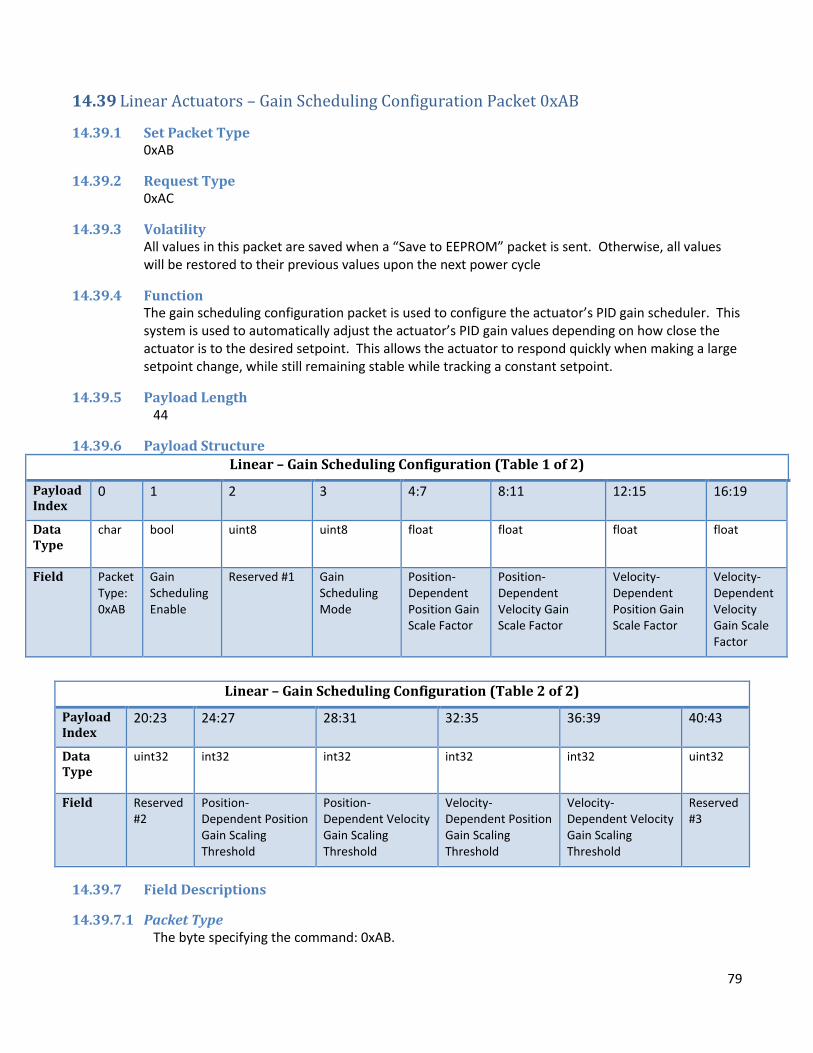
79
14.39 Linear Actuators – Gain Scheduling Configuration Packet 0xAB
14.39.1 Set Packet Type 0xAB
14.39.2 Request Type 0xAC
14.39.3 Volatility All values in this packet are saved when a “Save to EEPROM” packet is sent. Otherwise, all values will be restored to their previous values upon the next power cycle
14.39.4 Function The gain scheduling configuration packet is used to configure the actuator’s PID gain scheduler. This system is used to automatically adjust the actuator’s PID gain values depending on how close the actuator is to the desired setpoint. This allows the actuator to respond quickly when making a large setpoint change, while still remaining stable while tracking a constant setpoint.
14.39.5 Payload Length 44
14.39.6 Payload Structure
Linear – Gain Scheduling Configuration (Table 1 of 2)
Payload Index
0 1 2 3 4:7 8:11 12:15 16:19
Data Type
char bool uint8
uint8 float float float float
Field Packet Type: 0xAB
Gain Scheduling Enable
Reserved #1 Gain Scheduling Mode
Position-Dependent Position Gain Scale Factor
Position-Dependent Velocity Gain Scale Factor
Velocity-Dependent Position Gain Scale Factor
Velocity-Dependent Velocity Gain Scale Factor
Linear – Gain Scheduling Configuration (Table 2 of 2)
Payload Index
20:23 24:27 28:31 32:35 36:39 40:43
Data Type
uint32 int32 int32 int32 int32 uint32
Field Reserved #2
Position-Dependent Position Gain Scaling Threshold
Position-Dependent Velocity Gain Scaling Threshold
Velocity-Dependent Position Gain Scaling Threshold
Velocity-Dependent Velocity Gain Scaling Threshold
Reserved #3
14.39.7 Field Descriptions
14.39.7.1 Packet Type The byte specifying the command: 0xAB.

80
14.39.7.2 Gain Scheduling Enable If set to 1, the gain scheduling system will be enabled. If set to 0, the gain scheduling system will be disabled and the following fields will have no effect on system operation.
14.39.7.3 Reserved #1 This field does not currently affect actuator operation. However, it should be set to 0 to ensure compatibility with future firmware revisions.
14.39.7.4 Gain Scheduling Mode This field specifies which gain scheduling modes are enabled, depending on which bits are set: Bit 0: Enable position-dependent position gain scheduling Bit 1: Enable position-dependent velocity gain scheduling Bit 2: Enable velocity-dependent position gain scheduling Bit 3: Enable velocity-dependent velocity gain scheduling Bit 4-7: Reserved Note that enabling multiple gain scheduling options which affect the same gain value (e.g. position-dependent position gain scheduling and velocity-dependent position gain scheduling) may cause unexpected interactions. Operating the actuator in this manner should be done with caution.
14.39.7.5 Position-Dependent Position Gain Scale Factor Specifies the amount by which the position p-gain is reduced or increased when the actuator is near the specified position setpoint. This floating point number is directly multiplied by the p-gain value when the threshold condition is met and position-dependent position gain scheduling is enabled. This field has no effect in velocity control mode.
14.39.7.6 Position-Dependent Velocity Gain Scale Factor Specifies the amount by which the velocity p-gain is reduced or increased when the actuator is near the specified position setpoint. This floating point number is directly multiplied by the p-gain value when the threshold condition is met and position-dependent velocity gain scheduling is enabled. This field has no effect in velocity control mode.
14.39.7.7 Velocity-Dependent Position Gain Scale Factor Specifies the amount by which the position p-gain is reduced or increased when the actuator is near the specified velocity setpoint. This floating point number is directly multiplied by the p-gain value when the threshold condition is met and velocity-dependent position gain scheduling is enabled. This field has no effect in velocity control mode.
14.39.7.8 Velocity-Dependent Velocity Gain Scale Factor Specifies the amount by which the velocity p-gain is reduced or increased when the actuator is near the specified velocity setpoint. This floating point number is directly multiplied by the p-gain value when the threshold condition is met and velocity-dependent velocity gain scheduling is enabled.
14.39.7.9 Reserved #2 This field is not currently implemented and has no effect on system operation.
14.39.7.10 Position-Dependent Position Gain Scaling Threshold Specifies the position delta threshold (distance between current position and position setpoint, in milli-inches), below which the position-dependent position gain scale factor will be applied to the position p-gain.

81
14.39.7.11 Position-Dependent Velocity Gain Scaling Threshold Specifies the position delta threshold (distance between current position and position setpoint, in milli-inches), below which the position-dependent velocity gain scale factor will be applied to the velocity p-gain.
14.39.7.12 Velocity-Dependent Position Gain Scaling Threshold Specifies the velocity delta threshold (difference between current velocity and velocity setpoint, in milli-inches/minute), below which the velocity-dependent position gain scale factor will be applied to the position p-gain.
14.39.7.13 Velocity-Dependent Velocity Gain Scaling Threshold Specifies the velocity delta threshold (difference between current velocity and velocity setpoint, in milli-inches/minute), below which the velocity-dependent velocity gain scale factor will be applied to the velocity p-gain.
14.39.7.14 Reserved #3 This field is not currently implemented and has no effect on system operation.

82
14.40 Rotary Actuators – Position Linearization Configuration Packet 0xAD
14.40.1 Set Packet Type 0xAD
14.40.2 Request Type 0xAE Note that this request packet must include the desired start entry number as a 16-bit number and desired element count as an 8-bit number after the request type. Example request packet starting at entry 0 with 18 items:
14.40.3 Volatility Position sensor correction data is saved when a “Save to EEPROM” packet is sent. Otherwise, all values will be restored to their previous values upon the next power cycle
14.40.4 Function This packet is used to upload a position linearization table to the actuator. This is used to ensure that the reported position is accurate over the actuator’s entire range of motion. This procedure is usually done during manufacturing, therefore, this packet is not typically useful to end users.
14.40.5 Payload Length Varies - Up to 247
14.40.6 Payload Structure
Rotary – Position Linearization
Payload Index
0 1:2 3 4 5:6 7:8 – 245:246
Data Type
char uint16 uint8
uint8 uint16 int16
Field Packet Type: 0xAD
Start Entry Entry Count Reserved #1 Calibration Table Size
Position Sensor Correction Data
14.40.7 Field Descriptions
14.40.7.1 Packet Type The byte specifying the command: 0xAD.
14.40.7.2 Start Entry The unit’s internal calibration table contains 360 16-bit entries (one per degree), but the maximum packet size for actuator communication is 255 bytes. Therefore, access to the calibration table is performed using segments. This field specifies the first entry number to which the provided data should be written. If an invalid entry number is provided, the actuator will ignore it.
14.40.7.3 Entry Count Specifies the number of valid 16-bit table entries which are included in this packet. The packet will only be long enough to contain the number of entries specified in this field. The maximum recommended request size is 18 entries.

83
14.40.7.4 Reserved #1 This field is not used and does not currently affect actuator operation.
14.40.7.5 Calibration Table Size In packets sent from the actuator, this field contains the total size of the actuator’s internal calibration table. This size is currently fixed at 360 points for rotary actuators, but it may change in future actuator firmware revisions. In packets sent to the actuator, this field is ignored.
14.40.7.6 Position Sensor Correction Data This field contains one or more points of position correction data. Each point is a signed 16-bit integer which represents a correction, in milli-degrees, to the degree value at that point. For example, if the actuator reports 1.0 degrees, but an external encoder reports 1.05 degrees, the correction factor in position 1 of the correction table would be -50, representing 0.050 degrees of correction. The correction factor in position 0 must be 0; if a nonzero correction is provided for position 0 of page 0, it will be automatically replaced by a 0 value. The last correction factor of the last page should be less than 1 degree, otherwise unexpected behavior may occur.

84
14.41 Rotary Actuators – Raw Position Packet 0xAF
14.41.1 Set Packet Type 0xAF
14.41.2 Request Type 0xB1
14.41.3 Volatility All settings changed by this packet will be lost upon power on.
14.41.4 Function This packet is used to obtain a raw value from the position sensor, before any calibration, offsets, or linearization have been applied. This can be useful for debugging or troubleshooting. It is strongly recommended that customers use the System Info Packet in order to get the actuator position, as this will provide more useful information about the actuator’s position for virtually all practical applications.
14.41.5 Payload Length 13
14.41.6 Payload Structure
Rotary – Raw Position
Payload Index
0 1:4 5 4 5:8 9:12
Data Type
char uint32 uint8
uint8 uint32 int32
Field Packet Type: 0xAF
Averaging Count Mode Reserved #1 Reserved #2 Raw Position Data
14.41.7 Field Descriptions
14.41.7.1 Packet Type The byte specifying the command: 0xAF.
14.41.7.2 Averaging Count Number of position samples to average.
14.41.7.3 Mode The type of position to report: 0: Binary – reports raw binary data from position sensor 1: Degree – reports position sensor data in milli-degrees
14.41.7.4 Reserved #1 This field is not used and does not currently affect actuator operation.
14.41.7.5 Reserved #2 This field is not used and does not currently affect actuator operation.

85
14.41.7.6 Raw Position Data Contains the raw position data, averaged the specified number of times. As this data is unprocessed, positions near 0 degrees will not be handled well and may produce unexpected readings. When sending a set packet to the actuator, this field will be ignored and can be safely omitted.

86
14.42 Auto-Info Configuration Packet 0xB2
14.42.1 Set Packet Type 0xB2
14.42.2 Request Type 0xB3
14.42.3 Volatility All values in this packet are saved when a “Save to EEPROM” packet is sent. Otherwise, all values will be restored to their previous values upon the next power cycle
14.42.4 Function This function is used to enable auto-info responses from the actuator. The actuator will typically respond to most command packets with an Acknowledge Packet. In some systems, to maximize throughput, it may be desirable to receive System Info or other packets without sending a separate request packet. This command allows the user to select one or more packet types which will trigger a System Info or other packet(s) as a response instead of the default acknowledge packet.
14.42.5 Payload Length 42
14.42.6 Payload Structure
Auto-Info Configuration
Payload Index
0 1 2:5 6:9 10:41
Data Type
char bool uint32
uint32 uint8
Field Packet Type: 0xB2
Auto-Info Enable Reply Mode Reserved #1 Auto-Info enable bits
14.42.7 Field Descriptions
14.42.7.1 Packet Type The byte specifying the command: 0xB2
14.42.7.2 Auto-Info Enable If set to 1, auto-info will be enabled. If set to 0, auto-info will be disabled and the following fields will have no effect on system operation. If auto-info is disabled, all packets will return their default response (typically, an acknowledge packet).
14.42.7.3 Reply Mode This field specifies which packet(s) will be sent as a reply to the packets selected by the Auto-Info enable bits field. It is possible to select more than one response type in this field and the actuator will send multiple response packets per packet received. However, caution should be exercised when selecting multiple response packets as this may break packet handlers which assume only one packet will be returned per packet sent. This issue may be exacerbated on half-duplex

87
communication links such as RS-485. The following response packet types may be selected by setting the appropriate bit in this field: 0 – Acknowledge ‘A’ (default) 1 – System Info ‘P’ 2 – System Info 2 0xA2 3 – Velocity ‘H’ 4 – Faults ‘F’ 5 – Fault History ‘N’ 6 – Motion Profile Status 0x9C 7 – Failsafe Time Remaining 0x94
14.42.7.4 Reserved #1 This field does not currently affect actuator operation. However, it should be set to 0 to ensure compatibility with future firmware revisions.
14.42.7.5 Auto-Info enable bits This field indicates which packets will trigger an auto-info response vs the standard acknowledge packet response. This field functions as a bit field with one bit for each of the 255 valid packet types. It is arranged as a 32-byte array with index 0 of the array corresponding to byte 8 of the packet and index 32 corresponding to byte 39 of the packet. Bit 0 of index 0 corresponds to packet type 0x00, Bit 7 of index 0 corresponds to packet type 0x07, bit 0 of index 1 corresponds to packet type 0x09, and so on. For example, to set Auto-Info enabled for the Setpoint velocity ‘S’ (0x53 hex, 83 decimal) command, you would set the 83rd bit of this field (byte 10, bit 3) to 1. The general form is: byte# = command / 8, bit # = command mod 8. Commands corresponding to bits which are set to 0 will produce the standard Acknowledge packet response. Commands which return values other than acknowledge (such as system info requests, setpoint requests, velocity requests, etc. will ignore the auto-info function and continue to return only their default response packet.

88
14.43 Rotary Actuators – Persistent Revolution Counting Configuration Packet 0xB4
14.43.1 Set Packet Type 0xB4
14.43.2 Request Type 0xB5
14.43.3 Volatility All values in this packet are saved when a “Save to EEPROM” packet is sent. Otherwise, all values will be restored to their previous values upon the next power cycle
14.43.4 Function This packet is used to configure persistent revolution counting. It can be used to enable/disable the persistent revolution counting functionality, as well as to determine if the functionality is available on a particular unit. This packet is available in firmware versions 5.3 and later.
14.43.5 Payload Length 15
14.43.6 Payload Structure Persistent Revolution Counting Configuration
Payload Index
0 1:2 3:6 7:10 11:14
Data Type
char uint16 uint32
uint32 uint32
Field Packet Type: 0xB4
Persistent Rev Counting Flags
Reserved #1 Reserved #2 Reserved #3
14.43.7 Field Descriptions
14.43.7.1 Packet Type The byte specifying the command: 0xB4
14.43.7.2 Persistent Rev Counting Flags This field contains information about, and allows configuration of, the persistent revolution counting subsystem. The following bits are defined in this field: Bit 0 (Read only): Persistent rev counting available – if 1, indicates that this unit has the hardware necessary to support the persistent revolution counting feature. If 0, this unit is not capable of supporting persistent revolution counting, and writes to bit 1 will be ignored. Bit 1: Persistent rev counting enabled – Enables the persistent revolution counting feature when set to 1. The revolution counter will be saved and restored when the unit is power cycled. This feature is enabled by default on units which support the feature. After enabling this feature, it is recommended that to reset rotary counters to ensure the reported position is correct.
14.43.7.3 Reserved #1-#3 These fields do not currently affect actuator operation. However, they should be set to 0 to ensure compatibility with future firmware revisions.

89
14.44 CAN Bus Configuration Packet 0xB8 (Actuators equipped with CAN only)
14.44.1 Set Packet Type 0xB8
14.44.2 Request Type 0xB9
14.44.3 Volatility All values in this packet are saved when a “Save to EEPROM” packet is sent. Otherwise, all values will be restored to their previous values upon the next power cycle. Changes made will not take effect until the next power cycle.
14.44.4 Function This packet is used to configure CAN bus communication options. This packet is available in firmware versions 6.9 and later.
14.44.5 Payload Length 32
14.44.6 Payload Structure CAN Bus Configuration – 1 of 2
Payload Index
0 1-4 5-8 9 10-13 14-17
Data Type
char uint32 uint32 uint8 uint32 uint32
Field Packet Type: 0xB8 CAN baud rate Reserved #1 Use extended IDs Transmit base ID Receive base ID
CAN Bus Configuration – 2 of 2
Payload Index
18-21 22-25 26-29 30-31
Data Type
uint32 uint32 uint32 uint16
Field CAN TX message bitmask 1 Reserved #2 CAN message broadcast interval Reserved #3
14.44.7 Field Descriptions
14.44.7.1 Packet Type The byte specifying the command: 0xB8
14.44.7.2 CAN Baud Rate Sets the CAN communication baud rate in bits per second. Most common CAN baud rates up to 1Mbps are supported, with the exception of 800Kbps. If this field is set to 0, the CAN interface will be disabled and the actuator will not send or receive any CAN messages.
14.44.7.3 Reserved #1 This field does not currently affect actuator operation.

90
14.44.7.4 Use Extended IDs If set to 1, the actuator will communicate using extended (29-bit) CAN message identifiers. If set to 0, the actuator will use standard (11-bit) CAN message identifiers.
14.44.7.5 Transmit Base ID The actuator is capable of sending out a number of CAN messages to indicate various pieces of information about its current state. This field sets the CAN identifier of the first message type. Additional message types will be sent with an offset added to this ID. See the 2G Actuator CAN Messages document for more information on available CAN messages.
14.44.7.6 Receive Base ID The actuator is capable of receiving a number of CAN messages to control various actuator functions. This fields sets the CAN identifier of the first message type to be received. Additional message types can be sent with an offset added to this ID. See the 2G Actuator CAN Messages document for more information on available CAN messages.
14.44.7.7 CAN TX Message Bitmask 1 This field is used to set which status messages the actuator will send out. A message is enabled by setting a 1 in the corresponding bit position. For example, message offset 0 is enabled by setting bit 0 in this field. If this field is set to 0, the actuator will not send out any CAN status messages, but will still accept incoming CAN command messages. See the 2G Actuator CAN Messages document for more information on available CAN messages.
14.44.7.8 Reserved #2 This field does not currently affect actuator operation.
14.44.7.9 CAN Message Broadcast Interval Sets the interval (in ms) between CAN status messages sent out by the actuator. The system enforces a minimum value of 10ms between CAN messages.
14.44.7.10 Reserved #3 This field does not currently affect actuator operation.
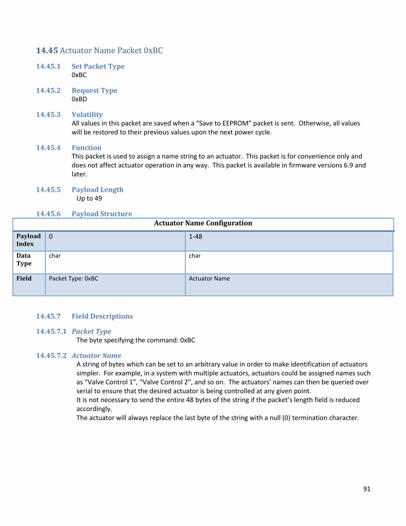
91
14.45 Actuator Name Packet 0xBC
14.45.1 Set Packet Type 0xBC
14.45.2 Request Type 0xBD
14.45.3 Volatility All values in this packet are saved when a “Save to EEPROM” packet is sent. Otherwise, all values will be restored to their previous values upon the next power cycle.
14.45.4 Function This packet is used to assign a name string to an actuator. This packet is for convenience only and does not affect actuator operation in any way. This packet is available in firmware versions 6.9 and later.
14.45.5 Payload Length Up to 49
14.45.6 Payload Structure
Actuator Name Configuration
Payload Index
0 1-48
Data Type
char char
Field Packet Type: 0xBC Actuator Name
14.45.7 Field Descriptions
14.45.7.1 Packet Type The byte specifying the command: 0xBC
14.45.7.2 Actuator Name A string of bytes which can be set to an arbitrary value in order to make identification of actuators simpler. For example, in a system with multiple actuators, actuators could be assigned names such as “Valve Control 1”, “Valve Control 2”, and so on. The actuators’ names can then be queried over serial to ensure that the desired actuator is being controlled at any given point. It is not necessary to send the entire 48 bytes of the string if the packet’s length field is reduced accordingly. The actuator will always replace the last byte of the string with a null (0) termination character.

92
15 Information Packets Information packets are receive-only, the fields cannot be set. They are sent out from the actuator in response to a request packet. Request packets are simple packets with one byte in the payload which specifies the command or type.
All information request packets must adhere to the following format:
15.1 Acknowledgement Packet ‘A’
15.1.1 Set Packet type ‘A’ (0x41)
15.1.2 Request type ‘a’ (0x61) The request packet, like other information request packets, contains only the packet type field in the payload; the Model Identifier cannot be set.
15.1.3 Volatility The Model identifier field contains static information set in the firmware that will not change.
15.1.4 Function This acknowledgement packet is sent in response to any valid packet that does not otherwise receive a response. It is also triggered by an acknowledgement request packet (‘a’). Ill-formed packets that do not pass a CRC check will not trigger this packet. This packet also contains 1 byte of basic identifying information about the actuator.
15.1.5 Payload Length 2
15.1.6 Payload Structure
Request Packet Template
Payload Index 0
Data Type Char
Field Packet Type
Acknowledgement Packet
Payload Index
0 1
Data Type
Char uint8
(Static)
Field Packet Type: ‘A’
Model Identifier

93
15.1.7 Field Descriptions
15.1.7.1 Packet Type The byte indicating the packet type: “A” (0x41)
15.1.7.2 Model Identifier Contains information about the actuator model.
Bit 0: 0 = Linear 1 = Rotary
Bits 1-2: 00 = Standard
01 = Valve Actuator Bits 3-6:
0000 = Series 2000 0001 = Series 3500 0010 = Series 4000 0011 = HPU 0100 = Series 6000
Bit 7: 0 = Generation 1 PID control algorithm 1 = Generation 2 PID control algorithm

94
15.2 Failsafe Time Remaining Information Packet 0x94
15.2.1 Receive Packet Type 0x94
15.2.2 Request Type 0x95
15.2.3 Volatility All values are volatile and will change according to conditions.
15.2.4 Function Triggered in response to a 0x95 request packet, contains time remaining until the failsafe timer expires. This value is reset when a system info request packet is received by the actuator.
15.2.5 Payload Length 5
15.2.6 Payload Structure
15.2.7 Field Descriptions
15.2.7.1 Packet Type The byte indicating the packet type: 0x94
15.2.7.2 Failsafe Time Remaining If failsafe mode is enabled, this represents the time remaining, in ms, until the failsafe timeout occurs (+/- 100ms). If failsafe mode is not enabled, or the timeout has already occurred, this will field will be value 0.
Failsafe Time Remaining Information
Payload Index
0 1:4
Data Type
char uint32
Field Packet Type: 0x94
Failsafe Time Remaining

95
15.3 Fault History Information Packet ‘N’
15.3.1 Receive Packet Type ‘N’ (0x4E)
15.3.2 Request Type ‘n’ (0x6E)
15.3.3 Volatility All values effected by this command are volatile. However, historic faults occupy a section of RAM that is not initialized when the board powers up. Although these values will be lost if the board loses power, in the event of a reset (such as by a watchdog timeout), these values will remain.
15.3.4 Function Triggered in response to an ‘n’ (0x6E) request packet, the fault history information packet contains information about historic faults. Unlike standard faults, historic faults can help to identify any faults that occurred and resolved, or that were present before the system was reset.
15.3.5 Payload Length 5
15.3.6 Payload Structure
15.3.7 Field Descriptions
15.3.7.1 Packet Type The byte indicating the packet type: ‘N’ (0x4E)
15.3.7.2 Motor Controller Historic Faults If the specified bit is 1, it indicates a fault.
Bit 0 – Short to supply, short to ground, or shorted motor winding fault.
Bit 1 – Under voltage, over-temp, or logic fault.
Bit 2 – Motor stalled (only if stall detection and stall fault are enabled).
15.3.7.3 Position Sensor Historic Faults If the specified bit is 1, it indicates a fault.
Bit 0 – Sensor communications fault.
Bit 1 – Sensor reading fault.
15.3.7.4 Temperature Historic Faults If the specified bit is 1, it indicates a fault.
Fault History Information
Payload Index
0 1 2 3 4
Data Type
char uint8
(Non-Initialized)
uint8
(Non-Initialized)
uint8
(Non-Initialized)
uint8
(Non-Initialized)
Field Packet Type: ‘N’
Motor Controller Faults Position Sensor Faults Temperature Faults Communication Faults

96
Bit 0 - Temp Sensor 1 Open Fault.
Bit 1 - Temp Sensor 1 Short Fault.
Bit 2 - Temp Sensor 2 Open Fault.
Bit 3 -Temp Sensor 2 Short Fault.
Bit 4 -Temp Sensor 1 High Temp Fault.
Bit 5 - Temp Sensor 1 Low Temp Fault.
Bit 6 - Temp Sensor 2 High Temp Fault.
Bit 7 - Temp Sensor 2 Low Temp Fault.
15.3.7.5 Communication Historic Faults If the specified bit is 1, it indicates a fault.
Bit 0 – Persistent CRC-failure fault.
Bit 1 – Persistent packet-misalignment fault.
Bit 2 – EEPROM write failure. This bit is set after a “Save to EEPROM” command if the write failed.
Bit 3 – EEPROM read failure. This bit is set at power-on if the actuator was unable to restore the saved configuration file from EEPROM. If this bit is set, the actuator’s configuration has been reset to defaults and all user-configurable settings will need to be reapplied.

97
15.4 Fault Information Packet ‘F’
15.4.1 Receive Packet Type ‘F’ (0x46)
15.4.2 Request Type ‘f’ (0x66)
15.4.3 Volatility All values are volatile and will change according to conditions.
15.4.4 Function Triggered in response to an ‘f’ (0x66) request packet, the fault information packet contains information about system fault states.
15.4.5 Payload Length 5
15.4.6 Payload Structure
15.4.7 Field Descriptions
15.4.7.1 Packet Type The byte indicating the packet type: ‘F’ (0x49)
15.4.7.2 Motor Controller Faults If the specified bit is 1, it indicates a fault.
Bit 0 – Short to supply, short to ground, or shorted motor winding fault.
Bit 1 – Under voltage, over-temp, or logic fault.
Bit 2 – Motor stalled (only if stall detection and stall fault are enabled).
15.4.7.3 Position Sensor Faults If the specified bit is 1, it indicates a fault.
Bit 0 – Sensor communications fault.
Bit 1 – Sensor reading fault.
15.4.7.4 Temperature Faults If the specified bit is 1, it indicates a fault.
Bit 0 - Temp Sensor 1 Open Fault.
Bit 1 - Temp Sensor 1 Short Fault.
Bit 2 - Temp Sensor 2 Open Fault.
Bit 3 -Temp Sensor 2 Short Fault.
Bit 4 -Temp Sensor 1 High Temp Fault.
Fault Information
Payload Index
0 1 2 3 4
Data Type
char uint8 uint8 uint8 uint8
Field Packet Type: ‘F’
Motor Controller Faults Position Sensor Faults Temperature Faults Communication Faults

98
Bit 5 - Temp Sensor 1 Low Temp Fault.
Bit 6 - Temp Sensor 2 High Temp Fault.
Bit 7 - Temp Sensor 2 Low Temp Fault.
15.4.7.5 Communication Faults If the specified bit is 1, it indicates a fault.
Bit 0 – Persistent CRC-failure fault.
Bit 1 – Persistent packet-misalignment fault.
Bit 2 – EEPROM write failure. This bit is set after a “Save to EEPROM” command if the write failed, and cleared after a successful write to EEPROM.
Bit 3 – EEPROM read failure. This bit is set at power-on if the actuator was unable to restore the saved configuration file from EEPROM. If this bit is set, the actuator’s configuration has been reset to defaults and all user-configurable settings will need to be reapplied.
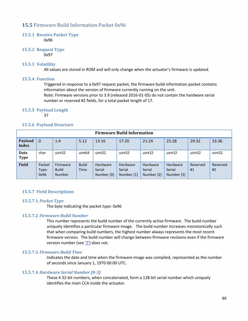
99
15.5 Firmware Build Information Packet 0x96
15.5.1 Receive Packet Type 0x96
15.5.2 Request Type 0x97
15.5.3 Volatility All values are stored in ROM and will only change when the actuator’s firmware is updated.
15.5.4 Function Triggered in response to a 0x97 request packet, the firmware build information packet contains information about the version of firmware currently running on the unit. Note: Firmware versions prior to 3.9 (released 2016-01-05) do not contain the hardware serial number or reserved #2 fields, for a total packet length of 17.
15.5.5 Payload Length 37
15.5.6 Payload Structure
15.5.7 Field Descriptions
15.5.7.1 Packet Type The byte indicating the packet type: 0x96
15.5.7.2 Firmware Build Number This number represents the build number of the currently active firmware. The build number uniquely identifies a particular firmware image. The build number increases monotonically such that when comparing build numbers, the highest number always represents the most recent firmware version. The build number will change between firmware revisions even if the firmware version number (see ‘?’) does not.
15.5.7.3 Firmware Build Time Indicates the date and time when the firmware image was compiled, represented as the number of seconds since January 1, 1970 00:00 UTC.
15.5.7.4 Hardware Serial Number [0-3] These 4 32-bit numbers, when concatenated, form a 128-bit serial number which uniquely identifies the main CCA inside the actuator.
Firmware Build Information
Payload Index
0 1:4 5:12 13:16 17:20 21:24 25:28 29:32 33:36
Data Type
char uint32 uint64 uint32 uint32 uint32 uint32 uint32 uint32
Field Packet Type: 0x96
Firmware Build Number
Build Time
Hardware Serial Number [0]
Hardware Serial Number [1]
Hardware Serial Number [2]
Hardware Serial Number [3]
Reserved #1
Reserved #2

100
15.5.7.5 Reserved #1 This field is currently unused and will not contain meaningful data.
15.5.7.6 Reserved #2 This field is currently unused and will not contain meaningful data.

101
15.6 Firmware Version Number Packet ‘?’
15.6.1 Receive Packet Type ‘?’ (0x63)
15.6.2 Request Type ‘?’ (0x63)
15.6.3 Volatility All values are stored in ROM and will only change when the actuator’s firmware is updated.
15.6.4 Function Triggered in response to a ‘?’ (0x63) request packet, the firmware build information packet contains information about the version of firmware currently running on the unit. The firmware version is typically only incremented when major new features or bug fixes are implemented. To verify if two units are running identical firmware revisions, see the Firmware Build Information Packet. Note: Firmware versions prior to 3.0 (released 2015-09-02) represent the firmware version as a single 32-bit float rather than two 16-bit integers.
15.6.5 Payload Length 5
15.6.6 Payload Structure
15.6.7 Field Descriptions
15.6.7.1 Packet Type The byte indicating the packet type: ‘?’ (0x63)
15.6.7.2 Firmware Major Version Represents the major version number of the current actuator firmware. For example, if the actuator was running firmware version 3.5, this field would contain the number 3.
15.6.7.3 Firmware Minor Version Represents the major version number of the current actuator firmware. For example, if the actuator was running firmware version 3.5, this field would contain the number 5.
Firmware Build Information
Payload Index
0 1:2 3:4
Data Type
char uint16 uint16
Field Packet Type: ‘?’ Firmware Major Version Firmware Minor Version

102
15.7 Scaled Position Information Packet 0x90
15.7.1 Receive Packet Type 0x90
15.7.2 Request Type 0x91
15.7.3 Volatility All values are volatile and will change according to conditions.
15.7.4 Function Triggered in response to a 0x91 request packet, returns the actuator’s scaled position.
15.7.5 Payload Length 5
15.7.6 Payload Structure
15.7.7 Field Descriptions
15.7.7.1 Packet Type The byte indicating the packet type: 0x90
15.7.7.2 Scaled Position Returns the actuator position as a signed integer in terms of the internal scaling function. Range: -10,000 to 10,000
Scaled Position Information
Payload Index
0 1:4
Data Type
char int32
Field Packet Type: 0x90
Scaled Position

103
15.8 Linear Actuators - System Status Information Packet ‘P’
15.8.1 Receive Packet Type ‘P’ (0x50)
15.8.2 Request Type ‘p’ (0x70)
15.8.3 Volatility All values are volatile and will change according to conditions.
15.8.4 Function Triggered in response to a ‘p’ (0x70) request packet, this is the primary system information containing basic information about the system’s status.
15.8.5 Payload Length 16
15.8.6 Payload Structure
15.8.7 Field Descriptions
15.8.7.1 Packet Type The byte indicating the packet type: ‘P’ (0x50)
15.8.7.2 Motor Status Indicates information about the motor’s status.
Below are the designations sent out from the actuator: Bits 0-2: 0000 – Motor is Off. 0001 – Motor is On. 0010 – Motor is On and Braking. 0011 – Motor is On and Coasting. Bit 5 – Reserved Bit 6: 0 – Hardware Brake is Disengaged. 1 – Hardware Brake is Engaged. Bit 7: 0 – Unit does not have hardware brake. 1 – Unit has hardware brake.
15.8.7.3 Motor Direction Indicates the motor’s direction of travel.
Linear - System Status Information
Payload Index
0 1 2 3:6 7 8 9:12 13:14 15
Data Type
char uint8 uint8 int32 int8 int8 int32 int16 uint8
Field Packet Type: ‘P’
Motor Status
Motor Direction
Absolute Position
Temperature 1
Temperature 2
Voltage Current Reserved
104
0 – Reverse. 1 – Forward.
15.8.7.4 Absolute Position Indicates the shaft position in mil. The relative position is not given explicitly by the actuator, it can be determined by the absolute position.
15.8.7.5 Temperature 1 Indicates the temperature reading on sensor 1, in degrees Celsius.
15.8.7.6 Temperature 2 Indicates the temperature reading on sensor 2, in degrees Celsius.
15.8.7.7 Voltage Indicates the voltage reading, in millivolts.
15.8.7.8 Current Indicates the board current reading, in milliamps. This value is signed; negative values indicate that the actuator is generating current. This may occur with certain actuator configurations when driven by an applied mechanical load.
15.8.7.9 Reserved This byte is reserved.

105
15.9 Rotary Actuators - System Status Information Packet ‘P’
15.9.1 Receive Packet Type ‘P’ (0x50)
15.9.2 Request Type ‘p’ (0x70).
15.9.3 Volatility All values are volatile and will change according to conditions.
15.9.4 Function Triggered in response to a ‘p’ (0x70) request packet, this is the primary system information containing basic information about the system’s status. Note that the actuator will report the speed even if the shaft is being driven by external forces. However, the motor must be on, braking, or coasting for a speed to be reported.
15.9.5 Payload Length 24
15.9.6 Payload Structure
15.9.7 Field Descriptions
15.9.7.1 Packet Type The byte indicating the packet type: ‘P’ (0x50)
Rotary – System Status Information (Table 1 of 2)
Payload Index
0 1 2 3:6 7:10 11:14
Data Type
char uint8 uint8 int32 int32 int32
Field Packet Type: ‘P’
Motor Status Motor Direction Absolute Position Motor Revolutions
Total Degrees
Rotary – System Status Information (Table 2 of 2)
Payload Index
15 16 17:20 21:22 23
Data Type int8 int8 int32 int16 uint8
Field Temperature 1 Temperature 2 Voltage Current Reserved

106
15.9.7.2 Motor Status Indicates information about the motor’s status.
Below are the designations sent out from the actuator: Bits 0-2: 0000 – Motor is Off. 0001 – Motor is On. 0010 – Motor is On and Braking. 0011 – Motor is On and Coasting. Bit 5 – Reserved Bit 6: 0 – Hardware Brake is Disengaged. 1 – Hardware Brake is Engaged. Bit 7: 0 – Unit does not have hardware brake. 1 – Unit has hardware brake.
15.9.7.3 Motor Direction Indicates the motor’s direction of travel.
0 – Reverse
1 – Forward
15.9.7.4 Absolute Position Indicates the shaft position in millidegrees. The relative position is not given explicitly by the actuator, it can be determined by the absolute position.
15.9.7.5 Motor Revolutions Indicates the total revolutions since power-on. A negative number indicates reverse rotations. The revolution counter may be reset with a ‘<’ packet.
15.9.7.6 Total Degrees Indicates the position, in millidegrees, relative to the total number of revolutions since power on or since the revolution counter was reset by a ‘<’ packet. Note: as this is a signed 32-bit integer, it will wrap around every 231-1 millidegrees (approximately 5965 revolutions). The Motor Revolutions field will continue to report motor revolutions correctly up to 231-1 revolutions. Be sure to account for this in your software design if you expect to accumulate a large number of motor revolutions in your application.
15.9.7.7 Temperature 1 Indicates the temperature reading on sensor 1, in degrees Celsius.
15.9.7.8 Temperature 2 Indicates the temperature reading on sensor 2, in degrees Celsius.
15.9.7.9 Voltage Indicates the voltage reading, in millivolts.
15.9.7.10 Current Indicates the board current reading, in milliamps. This value is signed; negative values indicate that the actuator is generating current. This may occur with certain actuator configurations when driven by an applied mechanical load.

107
15.9.7.11 Reserved This byte is reserved.
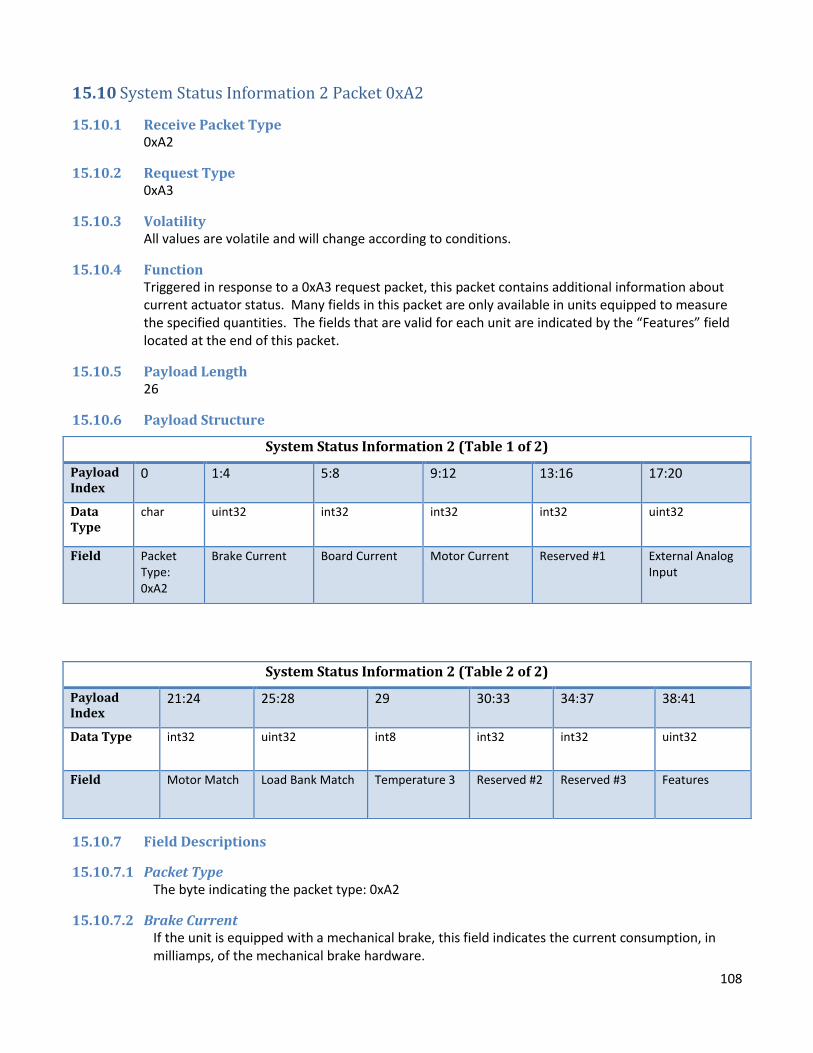
108
15.10 System Status Information 2 Packet 0xA2
15.10.1 Receive Packet Type 0xA2
15.10.2 Request Type 0xA3
15.10.3 Volatility All values are volatile and will change according to conditions.
15.10.4 Function Triggered in response to a 0xA3 request packet, this packet contains additional information about current actuator status. Many fields in this packet are only available in units equipped to measure the specified quantities. The fields that are valid for each unit are indicated by the “Features” field located at the end of this packet.
15.10.5 Payload Length 26
15.10.6 Payload Structure
15.10.7 Field Descriptions
15.10.7.1 Packet Type The byte indicating the packet type: 0xA2
15.10.7.2 Brake Current If the unit is equipped with a mechanical brake, this field indicates the current consumption, in milliamps, of the mechanical brake hardware.
System Status Information 2 (Table 1 of 2)
Payload Index
0 1:4 5:8 9:12 13:16 17:20
Data Type
char uint32 int32 int32 int32 uint32
Field Packet Type: 0xA2
Brake Current Board Current Motor Current Reserved #1 External Analog Input
System Status Information 2 (Table 2 of 2)
Payload Index
21:24 25:28 29 30:33 34:37 38:41
Data Type int32 uint32 int8 int32 int32 uint32
Field Motor Match Load Bank Match Temperature 3 Reserved #2 Reserved #3 Features

109
15.10.7.3 Board Current Indicates the board current reading, in milliamps. This value is signed; negative values indicate that the actuator is generating current. This may occur with certain actuator configurations when driven by an applied mechanical load. As this field is 32 bits wide, it allows for current readings larger than +/- 32.7 amps to be indicated.
15.10.7.4 Motor Current Indicates the current in the motor windings, in milliamps. Note that this value may be significantly higher than the board current reading, as motor current is recirculated in the motor under various operating conditions.
15.10.7.5 Reserved #1 This field is not currently used and will not contain meaningful information.
15.10.7.6 External Analog Input If the actuator is configured with analog control, this field will indicated the value, in millivolts, at the analog control input pin.
15.10.7.7 Motor Match This field indicates the pulse-width modulation match value currently being used to drive the motor.
15.10.7.8 Load Bank Match This field indicates the pulse-width modulation match value currently being used to drive the actuator’s internal load bank.
15.10.7.9 Temperature 3 Indicates the temperature reading on sensor 3, in degrees Celsius.
15.10.7.10 Reserved #2, Reserved #3 These fields are not currently used and will not contain meaningful information.
15.10.7.11 Features Indicates which fields in the System Status Information 2 packet will contain valid data based on the hardware configuration of the current actuator. Refer to the following table; if a bit is set to 1, the feature is available, otherwise it is not implemented and the corresponding field should not be considered to contain valid data.
Bit Feature
0-7 Not Used
8 Brake Current
9 Board Current
10 Motor Current
11 Reserved #1
12 External Analog Input
13 Motor Match
14 Load Bank Match
15 Temperature 3
16 Reserved #2

110
17 Reserved #3
18-31 Not Used

111
15.11 Linear Actuators – Velocity Information Packet ‘H’
15.11.1 Receive Packet Type ‘H’ (0x48)
15.11.2 Request Type ‘h’ (0x68)
15.11.3 Volatility All values are volatile and will change according to conditions.
15.11.4 Function Triggered in response to a ‘h’ (0x68) request packet, this packet contains information about motor and shaft speed. Note that the actuator will report the speed even if the shaft is being driven by external forces. However, the motor must be on, braking, or coasting for a speed to be reported.
15.11.5 Payload Length 9
15.11.6 Payload Structure
15.11.7 Field Descriptions
15.11.7.1 Packet Type The byte indicating the packet type: ‘H’ (0x48)
15.11.7.2 Motor Velocity Indicates the motor’s internal rotational velocity in mill-revolutions (1/1000th of a revolution) per minute. A negative value indicates that the motor is spinning in reverse.
15.11.7.3 Linear Velocity Specifies the shaft’s rate of travel in mil per minute. A positive value indicates that the shaft is extending. A negative value indicates that the shaft is retracting.
Linear – Velocity Information
Payload Index
0 1:4 5:8
Data Type
char int32 int32
Field Packet Type: ‘H’ Motor Velocity Linear Velocity

112
15.12 Rotary Actuators – Velocity Information Packet ‘H’
15.12.1 Receive Packet Type ‘H’ (0x48)
15.12.2 Request Type ‘h’ (0x68)
15.12.3 Volatility All values are volatile and will change according to new conditions.
15.12.4 Function Triggered in response to a ‘h’ (0x68) request packet, this packet contains information about motor and shaft speed. Note that the actuator will report the speed even if the shaft is being driven by external forces. However, the motor must be on, braking, or coasting for a speed to be reported.
15.12.5 Payload Length 9
15.12.6 Payload Structure
15.12.7 Field Descriptions
15.12.7.1 Packet Type The byte indicating the packet type: ‘H’ (0x48)
15.12.7.2 Motor Velocity Indicates the motor’s internal rotational velocity in millidegrees per minute. A negative value indicates that the motor is spinning in reverse.
15.12.7.3 Shaft Velocity Specifies the shaft’s rotational rate of travel in millidegrees per minute. The relationship between the shaft velocity and motor velocity is dependent on the gearing ratio between the motor and the shaft.
Rotary – Velocity Information
Payload Index
0 1:4 5:8
Data Type
char int32 int32
Field Packet Type: ‘H’
Motor Velocity Shaft Velocity

113
15.13 Motion Profile Status Packet 0x9C
15.13.1 Receive Packet Type 0x9C
15.13.2 Request Type 0x9D
15.13.3 Volatility All values are volatile and will change according to new conditions.
15.13.4 Function Triggered in response to a 0x9D request packet, this packet contains information about the currently active motion profile.
15.13.5 Payload Length 18
15.13.6 Payload Structure
15.13.7 Field Descriptions
15.13.7.1 Packet Type The byte indicating the packet type: 0x9C
15.13.7.2 Active Profile Mode Indicates the mode of the currently active motion profile, if any, according to the following enumerated values: 0 – No profile is currently active. 1 – Position to position profile (Setpoint absolute) 2 – Velocity to velocity profile (Setpoint velocity) All other values are currently undefined.
15.13.7.3 Profile Time Remaining Indicates the time remaining in the motion profile, in ms. For a position profile, this value may be zero for several seconds before the actuator reaches its target position, as the motion profile subsystem automatically switches the control mode to direct PID control near the end of any position profile. The “Active Profile Mode” field will indicate whether or not a profile is active regardless of the time remaining.
15.13.7.4 Reserved #1, Reserved #2, Reserved #3 These fields are currently unused and will not contain meaningful data.
Rotary – Velocity Information
Payload Index
0 1 2:5 6:9 10:13 14:17
Data Type char uint8 uint32 uint32 uint32 uint32
Field Packet Type: 0x9C
Active Profile Mode
Profile Time Remaining
Reserved #1
Reserved #2
Reserved #3

114
15.14 CAN Bus Status Packet 0xBA (Actuators equipped with CAN only)
15.14.1 Receive Packet Type 0xBA
15.14.2 Request Type 0xBB
15.14.3 Volatility All values are volatile and will change according to new conditions.
15.14.4 Function Triggered in response to a 0xBB request packet, this packet contains information about the actuator’s CAN bus interface. This field is available on actuator firmware version 6.9 and later.
15.14.5 Payload Length 8
15.14.6 Payload Structure
15.14.7 Field Descriptions
15.14.7.1 Packet Type The byte indicating the packet type: 0xBA
15.14.7.2 CAN System Status Indicates the current status of the CAN bus interface. Bit 0 – Error Warning: CAN TX and/or RX error levels have increased past the warning threshold Bit 1 – Bus Error: If set, the CAN transceiver has entered Bus Off state due to an excess of CAN transmit errors.
15.14.7.3 TX Error Count The number of detected CAN transmit errors.
15.14.7.4 RX Error Count The number of detected CAN receive errors.
15.14.7.5 Reserved This field is currently unused and will not contain meaningful data.
Rotary – Velocity Information
Payload Index
0 1 2 3 4:7
Data Type char uint8 uint8 uint8 uint32
Field Packet Type: 0xBA
CAN system status
TX Error Count RX Error Count Reserved
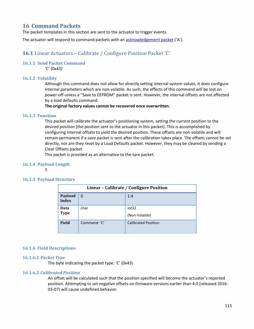
115
16 Command Packets The packet templates in this section are sent to the actuator to trigger events.
The actuator will respond to command packets with an acknowledgement packet (‘A’).
16.1 Linear Actuators – Calibrate / Configure Position Packet ‘C’
16.1.1 Send Packet Command ‘C’ (0x43)
16.1.2 Volatility Although this command does not allow for directly setting internal system values, it does configure internal parameters which are non-volatile. As such, the effects of this command will be lost on power-off unless a “Save to EEPROM” packet is sent. However, the internal offsets are not affected by a load defaults command. The original factory values cannot be recovered once overwritten.
16.1.3 Function This packet will calibrate the actuator’s positioning system, setting the current position to the desired position (the position sent to the actuator in this packet). This is accomplished by configuring internal offsets to yield the desired position. These offsets are non-volatile and will remain permanent if a save packet is sent after the calibration takes place. The offsets cannot be set directly, nor are they reset by a Load Defaults packet. However, they may be cleared by sending a Clear Offsets packet. This packet is provided as an alternative to the tare packet.
16.1.4 Payload Length 5
16.1.5 Payload Structure
16.1.6 Field Descriptions
16.1.6.1 Packet Type The byte indicating the packet type: ‘C’ (0x43)
16.1.6.2 Calibrated Position An offset will be calculated such that the position specified will become the actuator’s reported position. Attempting to set negative offsets on firmware versions earlier than 4.0 (released 2016-03-07) will cause undefined behavior.
Linear – Calibrate / Configure Position
Payload Index
0 1:4
Data Type
char int32
(Non-Volatile)
Field Command: ‘C’ Calibrated Position

116
16.2 Rotary Actuators – Calibrate / Configure Position Packet ‘C’
16.2.1 Send Packet Command ‘C’ (0x43)
16.2.2 Volatility Although this command does not allow for directly setting internal system values, it does configure internal parameters which are non-volatile. As such, the effects of this command will be lost on power-off unless a “Save to EEPROM” packet is sent. However, the internal offsets are not affected by a load defaults command. The original factory values cannot be recovered once overwritten.
16.2.3 Function This packet will calibrate the actuator’s positioning system, setting the current position to the desired position (the position sent to the actuator in this packet). This is accomplished by configuring internal offsets to yield the desired position. These offsets are non-volatile and will remain permanent if a save packet is sent after the calibration takes place. The offsets cannot be set directly, nor are they reset by a Load Defaults packet. However, they may be cleared by sending a Clear Offsets packet. This packet is provided as an alternative to the tare packet.
16.2.4 Payload Length 5
16.2.5 Payload Structure
16.2.6 Field Descriptions
16.2.6.1 Packet Type The byte indicating the packet type: ‘C’ (0x43)
16.2.6.2 Calibrated Position An offset will be calculated such that the position specified will become the actuator’s reported position. Valid values are 0 to 359999 millidegrees.
Rotary - Calibrate/Configure Position Command
Payload Index
0 1:4
Data Type
char int32
(Non-Volatile)
Field Command: ‘C’ Calibrated Position

117
16.3 Calibrate / Configure Current Packet 0xAA
16.3.1 Send Packet Command 0xAA
16.3.2 Volatility This command configures internal parameters which are non-volatile. As such, the effects of this command will be lost on power-off unless a “Save to EEPROM” packet is sent. However, the internal offsets are not affected by a load defaults command. The original factory values cannot be recovered once overwritten.
16.3.3 Function This packet will calibrate the actuator’s current monitoring system, setting either the current reading to the desired value by computing an offset internally, or by proving an offset directly. These offsets are non-volatile and will remain permanent if a save packet is sent after the calibration takes place. The offsets are not reset by a Load Defaults packet, but may be reset by sending this packet in mode 0. Note that resetting the offset returns it to 0, not the factory value.
16.3.4 Payload Length 6
16.3.5 Payload Structure
16.3.6 Field Descriptions
16.3.6.1 Packet Type The byte indicating the packet type: 0xAA
16.3.6.2 Offset Mode Specifies the current offset update mode according to the following enumerated values: 0 – Reset offset: The internal current offset is reset to zero. The offset value field must also be set to 0 for this to take effect. 1 — Set Offset: The internal current offset is set to value specified in the Offset Value field. 2 — Set Current: The internal current is calculated such that the reported current becomes the value specified in the Offset Value field.
16.3.6.3 Offset Value Contains the value to be used to update the current offset. The exact function of this field varies depending on the mode specified in the “Offset Mode” field.
Rotary - Calibrate/Configure Position Command
Payload Index
0 1 2:5
Data Type char uint8 int32
Field Command: 0xAA
Offset Mode Offset Value

118
16.4 Clear Offsets Command Packet ‘-‘
16.4.1 Send Packet Command ‘-‘ (0x2D)
16.4.2 Volatility Although this command does not allow for directly setting internal system values, it does configure internal parameters which are non-volatile. As such, the effects of this command will be lost on power-off unless a “Save to EEPROM” packet is sent. However, the internal offsets are not affected by a load defaults command. The original factory values cannot be recovered once overwritten.
16.4.3 Function Resets the internal offsets that were configured during calibrations. Note that these offsets do not refer to relative positioning, but the offsets that were factory-calibrated for precise absolute positioning. After receiving this packet, the actuator will report the raw position that it reads from the position sensor. If the update position command (0xA0) has been used since the actuator was last powered on, the clear offsets command will also reset any position offsets set up by that command. If persistent revolution counting is enabled, this reset will take effect immediately and will be persistent across power cycles, even if a “Save to EEPROM” command is not issued. It is advisable to calibrate the actuator after issuing this command, by using either a Calibrate Position packet ‘C’ or a Tare ‘#’ packet.
16.4.4 Payload Length 1
16.4.5 Payload Structure
16.4.6 Field Descriptions
16.4.6.1 Command Indicates the command being issued: ‘-‘ (0x2D).
Clear Offsets Command
Payload Index 0
Data Type char
Field Command: ‘-‘

119
16.5 In-System Programming Update Command Packet ‘~‘
16.5.1 Send Packet Command ‘~‘ (0x7E)
16.5.2 Volatility This command will cause all non-volatile parameters that have changed since the last save to be lost when the system loses power unless a “Save to EEPROM” packet is sent. When new firmware is loaded, the system will try to recover data stored in EEPROM from the previous firmware. This carries some risk that the data is incompatible, so saving important tuning values or other information off-board is advisable.
16.5.3 Function Puts the actuator microcontroller into a bootloader mode ready for In-System Programming. This allows updating the actuator firmware with a new .hex file over serial. The 2G Actuator GUI application or lpc21isp.exe may be used to load the hex file after the actuator receives the ISP/IAP packet. The system will require a power cycle after successful programming, if programming is not initiated, or if programming fails before becoming responsive again.
16.5.4 Payload Length 1
16.5.5 Payload Structure
16.5.6 Field Descriptions
16.5.6.1 Command Indicates the command being issued: ‘~‘ (0x7E).
In-System Programming Command
Payload Index 0
Data Type char
Field Command: ‘~‘

120
16.6 Load Default (Factory) Configuration Command Packet ‘@‘
16.6.1 Send Packet Command ‘@‘ (0x40)
16.6.2 Volatility All non-volatile system values will change to their default values upon receiving this command.
16.6.3 Function Loads default actuator settings. In order for the default settings to persist, a save command must be sent, otherwise the last settings that were saved will be loaded on the next power cycle. Most settings will be set to their default value, including relative zero location (default is 0). Loading defaults does not recover factory calibration offsets; calibration must always be done manually.
16.6.4 Payload Length 1
16.6.5 Payload Structure
16.6.6 Field Descriptions
16.6.6.1 Command Indicates the command being issued: ‘@‘ (0x40).
Load Default Configuration Command
Payload Index 0
Data Type char
Field Command: ‘@‘
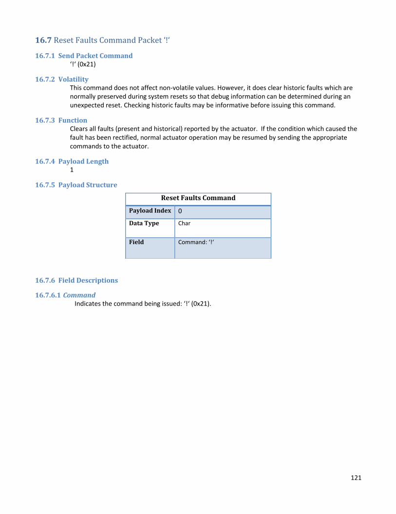
121
16.7 Reset Faults Command Packet ‘!‘
16.7.1 Send Packet Command ‘!‘ (0x21)
16.7.2 Volatility This command does not affect non-volatile values. However, it does clear historic faults which are normally preserved during system resets so that debug information can be determined during an unexpected reset. Checking historic faults may be informative before issuing this command.
16.7.3 Function Clears all faults (present and historical) reported by the actuator. If the condition which caused the fault has been rectified, normal actuator operation may be resumed by sending the appropriate commands to the actuator.
16.7.4 Payload Length 1
16.7.5 Payload Structure
16.7.6 Field Descriptions
16.7.6.1 Command Indicates the command being issued: ‘!‘ (0x21).
Reset Faults Command
Payload Index 0
Data Type Char
Field Command: ‘!‘

122
16.8 Rotary Actuators - Reset Rotary Counters Command Packet ‘<‘
16.8.1 Send Packet Command ‘<‘ (0x3C)
16.8.2 Volatility This command does not affect non-volatile values. However, If persistent revolution counting is enabled, the new position will be remembered across actuator resets and power cycles.
16.8.3 Function Resets the total revolutions to 0. Unless this packet is received, the actuator will report the total number of revolutions since the actuator was powered on. If the update position command (0xA0) has been used since the actuator was last powered on, this command will also reset the actuator’s reported position to its default value.
16.8.4 Payload Length 1
16.8.5 Payload Structure
16.8.6 Field Descriptions
16.8.6.1 Command Indicates the command being issued: ‘<‘ (0x3C).
Rotary – Reset Rotary Counters Command
Payload Index 0
Data Type char
Field Command: ‘<‘

123
16.9 Reset System Command Packet ‘=‘
16.9.1 Send Packet Command ‘=‘ (0x3D)
16.9.2 Volatility This command will cause all non-volatile parameters that have changed since the last save to be lost when the system loses power unless a “Save to EEPROM” packet is sent. There are a few internal variables, such as historic faults, that will maintain their values during a reset.
16.9.3 Function Resets the system, causing the board to reload the operating system. This command is nearly identical to doing a power cycle.
16.9.4 Payload Length 1
16.9.5 Payload Structure
16.9.6 Field Descriptions
16.9.6.1 Command Indicates the command being issued: ‘=‘ (0x3D).
Reset System Command
Payload Index 0
Data Type char
Field Command: ‘=‘

124
16.10 Reverse Direction Command Packet ‘&’
16.10.1 Send Packet Command ‘&‘ (0x26)
16.10.2 Volatility This command has no effect on non-volatile values.
16.10.3 Function If the motor is on, reverses the direction that the motor is spinning. In general, this command is issued when the actuator is under manual control running at a fixed match or duty cycle. If the control loop is currently running and seeking a setpoint, the control loop will quickly correct this command.
16.10.4 Payload Length 1
16.10.5 Payload Structure
16.10.6 Field Descriptions
16.10.6.1 Command Indicates the command being issued: ‘&‘ (0x26).
Reverse Direction Command
Payload Index 0
Data Type char
Field Command: ‘&‘

125
16.11 Save Configuration to EEPROM Command Packet ‘$‘
16.11.1 Send Packet Command ‘$‘ (0x24)
16.11.2 Volatility All non-volatile system values will be saved and loaded upon the next power up after this command is issued.
16.11.3 Function Saves the current configuration to EEPROM. Without sending this command, configurations that are sent to the actuator will be lost when the unit is powered down. It is recommended that any changes in configuration are tested before sending this packet.
16.11.4 Payload Length 1
16.11.5 Payload Structure
16.11.6 Field Descriptions
16.11.6.1 Command Indicates the command being issued: ‘$‘ (0x24).
Save Configuration Command
Payload Index 0
Data Type char
Field Command: ‘$‘
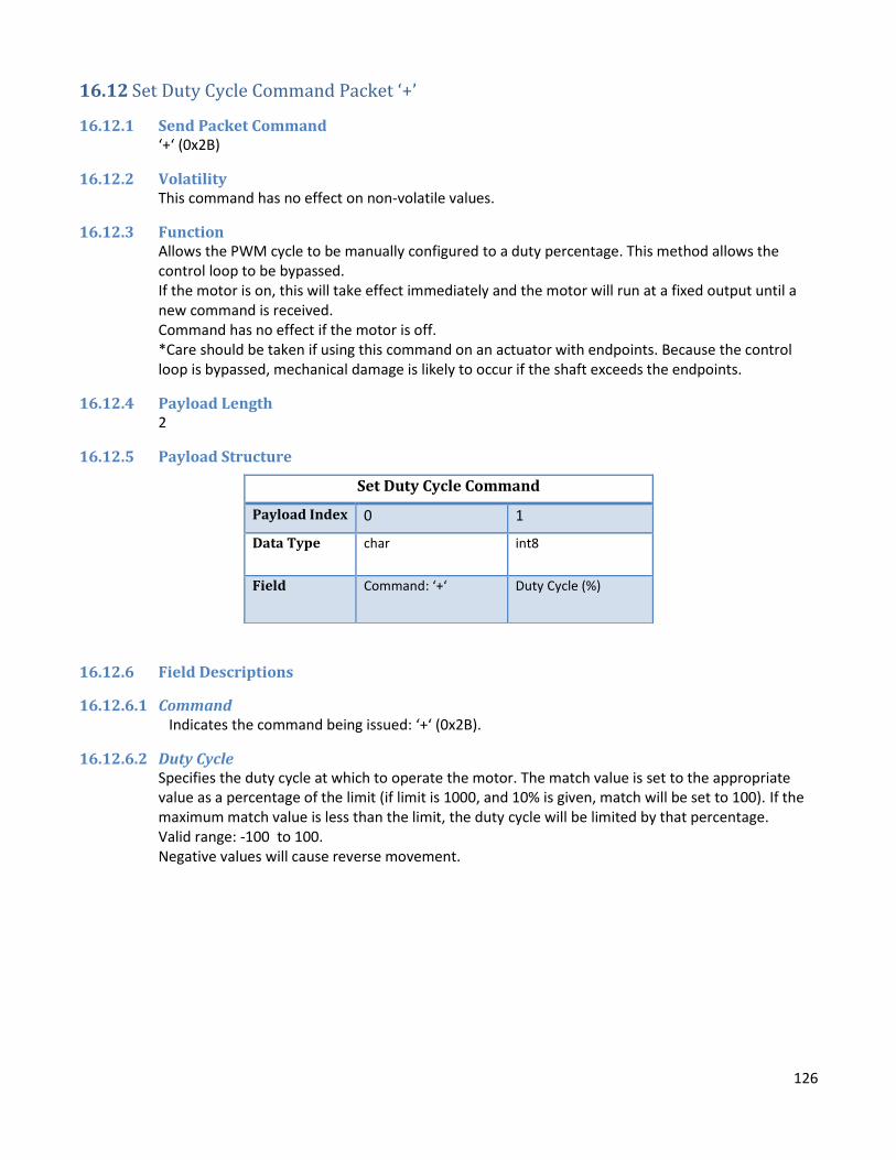
126
16.12 Set Duty Cycle Command Packet ‘+’
16.12.1 Send Packet Command ‘+‘ (0x2B)
16.12.2 Volatility This command has no effect on non-volatile values.
16.12.3 Function Allows the PWM cycle to be manually configured to a duty percentage. This method allows the control loop to be bypassed. If the motor is on, this will take effect immediately and the motor will run at a fixed output until a new command is received. Command has no effect if the motor is off. *Care should be taken if using this command on an actuator with endpoints. Because the control loop is bypassed, mechanical damage is likely to occur if the shaft exceeds the endpoints.
16.12.4 Payload Length 2
16.12.5 Payload Structure
16.12.6 Field Descriptions
16.12.6.1 Command Indicates the command being issued: ‘+‘ (0x2B).
16.12.6.2 Duty Cycle Specifies the duty cycle at which to operate the motor. The match value is set to the appropriate value as a percentage of the limit (if limit is 1000, and 10% is given, match will be set to 100). If the maximum match value is less than the limit, the duty cycle will be limited by that percentage. Valid range: -100 to 100. Negative values will cause reverse movement.
Set Duty Cycle Command
Payload Index 0 1
Data Type char int8
Field Command: ‘+‘ Duty Cycle (%)

127
16.13 Set Match Value Command Packet ‘^’
16.13.1 Send Packet Command ‘^‘ (0x5E)
16.13.2 Volatility This command has no effect on non-volatile values.
16.13.3 Function This packet allows for manual control of the match value. This bypasses the control loop and the actuator will run at a fixed output until the motor is turned off or a new control packet is received. If the motor is on, this will take effect immediately and the motor will run at a fixed output until a new command is received. Command has no effect if the motor is off. *Care should be taken if using this command on an actuator with endpoints. Because the control loop is bypassed, mechanical damage is likely to occur if the shaft exceeds the endpoints.
16.13.4 Payload Length 3
16.13.5 Payload Structure
16.13.6 Field Descriptions
16.13.6.1 Command Indicates the command being issued: ‘^‘ (0x5E).
16.13.6.2 Match Value Sets the match value (the duty portion of the PWM cycle). The match value is limited by the maximum match value setting. Negative values will cause reverse movement.
Set Match Value Command
Payload Index 0 1:2
Data Type char int16
Field Command: ‘^‘ Match Value

128
16.14 Tare Command Packet ‘#‘
16.14.1 Send Packet Command ‘#‘ (0x23)
16.14.2 Volatility Although this command does not allow for directly setting internal system values, it does configure internal parameters which are non-volatile. As such, the effects of this command will be lost on power-off unless a “Save to EEPROM” packet is sent. However, the internal offsets are not affected by a load defaults command. The original factory values cannot be recovered once overwritten. If persistent revolution counting is enabled, sending a tare command without also sending a “Save to EEPROM” command may result in an unexpected position value the next time the actuator is power cycled or reset.
16.14.3 Function This packet provides a means of calibrating the absolute position of the actuator. Factory calibration is performed on each actuator, so it is not advisable to perform this action unless it is needed. When this packet is received, it reconfigures the internal offsets so that the current physical location of the shaft is calibrated as absolute position 0.
16.14.4 Payload Length 1
16.14.5 Payload Structure
16.14.6 Field Descriptions
16.14.6.1 Command Indicates the command being issued: ‘#‘ (0x23).
Tare Command
Payload Index 0
Data Type Char
Field Command: ‘#‘

129
16.15 Rotary Actuators – Update Position Packet 0xA0
16.15.1 Send Packet Command 0xA0
16.15.2 Volatility This command has no effect on non-volatile values. The position offset will be reset when the actuator is reset or power is lost on firmware version 5.2 and earlier, or if persistent rev counting is disabled on firmware 5.3 or later. If persistent revolution counting is enabled, the actuator will remember the updated position across power cycles. However, some combinations of update settings may not be properly saved across power cycles. In particular, if total degrees and revolution count are set separately (e.g. by using bits 0 and 3 or 1 and 4), the revolution count will take precedence after a reset. If this is an issue for your application, you may want to consider disabling persistent revolution counting, or resetting rotary counters before sending your desired position.
16.15.3 Function This packet provides a means of applying a position offset to the reported position of the actuator. This may be useful, for example, to synchronize the reported actuator position with the state of an external system coupled to the actuator after the actuator has been power cycled. All offsets applied by this command may be reset by using the ‘<’ Packet. Offsets will also be reset when the Tare or Calibrate packets are sent. Updating the position of a unit using this packet while the unit’s motor is on and a setpoint is active will cause unpredictable behavior and is strongly discouraged.
16.15.4 Payload Length 14
16.15.5 Payload Structure
16.15.6 Field Descriptions
16.15.6.1 Command Indicates the command being issued: 0xA0.
16.15.6.2 Update Mask Indicates which fields to update based on bits set: 0 – Total degrees (from Total Degrees field) 1 – Revolution Counter (from Total Degrees field) 2 – Absolute Position (from Total Degrees field) 3 – Revolution Counter (from Revolution Count field) 4 – Total Degrees (from Revolution Count field) 5-7 – Reserved
Update Position Command
Payload Index
0 1 2:5 6:9 10:13
Data Type
Char uint8 int32 int32 int32
Field Command: 0xA0
Update Mask Revolution Count
Total Degrees Reserved

130
Depending on bits selected, revolution counter and absolute position will be calculated and updated based on the position offset(s) provided. If both bits 1 and 3 are set, bit 3 will take precedence. If both bits 0 and 4 are set, bit 4 will take precedence. The absolute position, if selected, will always be calculated based on the provided total degrees value. Some combinations of update bits are valid, but may not make sense for most applications. For example, bit 2 should typically be set when bit 0 is set, but not when bit 4 is set, otherwise an offset will develop between total degrees and absolute position. The actuator will continue to function in this state, but the difference between reported absolute position and reported total degrees may cause confusion.
16.15.6.3 Revolution Count Specifies the desired new value for the revolution counter. The value in this field will take precedence over the value of revolution count calculated from the Total Degrees field if both are selected by the respective bits in the Update Mask field. It bit 4 is selected, the value of total degrees will be calculated from this field * 360 + the current absolute position.
16.15.6.4 Total Degrees Specifies the desired new value for the “Total Degrees” field as reported by the actuator. This field will be used to update the revolution counter if bit 1 is set. The remainder of this value divided by 360 degrees will be used to update the absolute position field if bit 2 is selected in the update mask field.
16.15.6.5 Reserved This field is not implemented and currently has no effect on actuator operation.

131
17 Example Packet #1
18 Example Packet #2
Request System Info Packet – “p” without addressing.
Byte
Star
t D
elim
iter
"<”
0 1 2 End
Delim
iter “>”
Data Type
uint8 char uint8
Field Length 1
Command ‘p’
Cyclical Redundancy Check on bytes 0-1.
Bytes used in CRC calculation:
Integer Value
60 1 112 66 62
Hex 0x3c 0x01 0x70 0x42 0x3e
Packet String:
0x3c0x010x700x420x3e
Request System Info Packet – “p” with addressing.
Byte
Star
t D
elim
iter
"[”
0 1 2 3 End
Delim
iter “]”
Data Type
uint8 uint8 char uint8
Field Address
3
Length
1
Command
‘p’
Cyclical Redundancy Check on bytes 0-2.
Bytes used in CRC calculation:
Integer Value
91 3 1 112 255 93
Hex 0x5b 0x03 0x01 0x70 0xff 0x5d
Packet String:
0x5b0x030x010x700xff0x5d

132
19 Example CRC Functions 2G’s packeting system uses an 8-bit CRC with a polynomial of x8 + x5 + x4 + 1. Example lookup table-based implementations of this CRC are shown below in both C and python.
19.1 CRC Function in C CRC Algorithm
CRC Table CRC function
const uint8_t CRC8_TABLE[] = { 0x00,0x07,0x0E,0x09,0x1C,0x1B,0x12,0x15,0x38,0x3F, 0x36,0x31,0x24,0x23,0x2A,0x2D,0x70,0x77,0x7E,0x79, 0x6C,0x6B,0x62,0x65,0x48,0x4F,0x46,0x41,0x54,0x53, 0x5A,0x5D,0xE0,0xE7,0xEE,0xE9,0xFC,0xFB,0xF2,0xF5, 0xD8,0xDF,0xD6,0xD1,0xC4,0xC3,0xCA,0xCD,0x90,0x97, 0x9E,0x99,0x8C,0x8B,0x82,0x85,0xA8,0xAF,0xA6,0xA1, 0xB4,0xB3,0xBA,0xBD,0xC7,0xC0,0xC9,0xCE,0xDB,0xDC, 0xD5,0xD2,0xFF,0xF8,0xF1,0xF6,0xE3,0xE4,0xED,0xEA, 0xB7,0xB0,0xB9,0xBE,0xAB,0xAC,0xA5,0xA2,0x8F,0x88, 0x81,0x86,0x93,0x94,0x9D,0x9A,0x27,0x20,0x29,0x2E, 0x3B,0x3C,0x35,0x32,0x1F,0x18,0x11,0x16,0x03,0x04, 0x0D,0x0A,0x57,0x50,0x59,0x5E,0x4B,0x4C,0x45,0x42, 0x6F,0x68,0x61,0x66,0x73,0x74,0x7D,0x7A,0x89,0x8E, 0x87,0x80,0x95,0x92,0x9B,0x9C,0xB1,0xB6,0xBF,0xB8, 0xAD,0xAA,0xA3,0xA4,0xF9,0xFE,0xF7,0xF0,0xE5,0xE2, 0xEB,0xEC,0xC1,0xC6,0xCF,0xC8,0xDD,0xDA,0xD3,0xD4, 0x69,0x6E,0x67,0x60,0x75,0x72,0x7B,0x7C,0x51,0x56, 0x5F,0x58,0x4D,0x4A,0x43,0x44,0x19,0x1E,0x17,0x10, 0x05,0x02,0x0B,0x0C,0x21,0x26,0x2F,0x28,0x3D,0x3A, 0x33,0x34,0x4E,0x49,0x40,0x47,0x52,0x55,0x5C,0x5B, 0x76,0x71,0x78,0x7F,0x6A,0x6D,0x64,0x63,0x3E,0x39, 0x30,0x37,0x22,0x25,0x2C,0x2B,0x06,0x01,0x08,0x0F, 0x1A,0x1D,0x14,0x13,0xAE,0xA9,0xA0,0xA7,0xB2,0xB5, 0xBC,0xBB,0x96,0x91,0x98,0x9F,0x8A,0x8D,0x84,0x83, 0xDE,0xD9,0xD0,0xD7,0xC2,0xC5,0xCC,0xCB,0xE6,0xE1, 0xE8,0xEF,0xFA,0xFD,0xF4,0xF3 };
/* Note that the CRC needs to initialized to 0 For 2G packets, the start and end delimiter are not included in the CRC calculation.*/ uint8_t compute_crc8(uint8 crc, uint8* buffer, uint16 len){ uint16 i; for(i=0; i<len; i++){ crc = CRC8_TABLE[crc ^ buffer[i]]; } return crc; }
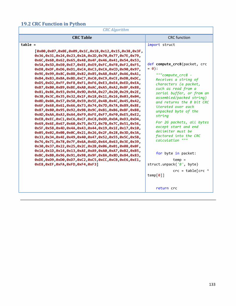
133
19.2 CRC Function in Python CRC Algorithm
CRC Table CRC function
table =
[0x00,0x07,0x0E,0x09,0x1C,0x1B,0x12,0x15,0x38,0x3F, 0x36,0x31,0x24,0x23,0x2A,0x2D,0x70,0x77,0x7E,0x79, 0x6C,0x6B,0x62,0x65,0x48,0x4F,0x46,0x41,0x54,0x53, 0x5A,0x5D,0xE0,0xE7,0xEE,0xE9,0xFC,0xFB,0xF2,0xF5, 0xD8,0xDF,0xD6,0xD1,0xC4,0xC3,0xCA,0xCD,0x90,0x97, 0x9E,0x99,0x8C,0x8B,0x82,0x85,0xA8,0xAF,0xA6,0xA1, 0xB4,0xB3,0xBA,0xBD,0xC7,0xC0,0xC9,0xCE,0xDB,0xDC, 0xD5,0xD2,0xFF,0xF8,0xF1,0xF6,0xE3,0xE4,0xED,0xEA, 0xB7,0xB0,0xB9,0xBE,0xAB,0xAC,0xA5,0xA2,0x8F,0x88, 0x81,0x86,0x93,0x94,0x9D,0x9A,0x27,0x20,0x29,0x2E, 0x3B,0x3C,0x35,0x32,0x1F,0x18,0x11,0x16,0x03,0x04, 0x0D,0x0A,0x57,0x50,0x59,0x5E,0x4B,0x4C,0x45,0x42, 0x6F,0x68,0x61,0x66,0x73,0x74,0x7D,0x7A,0x89,0x8E, 0x87,0x80,0x95,0x92,0x9B,0x9C,0xB1,0xB6,0xBF,0xB8, 0xAD,0xAA,0xA3,0xA4,0xF9,0xFE,0xF7,0xF0,0xE5,0xE2, 0xEB,0xEC,0xC1,0xC6,0xCF,0xC8,0xDD,0xDA,0xD3,0xD4, 0x69,0x6E,0x67,0x60,0x75,0x72,0x7B,0x7C,0x51,0x56, 0x5F,0x58,0x4D,0x4A,0x43,0x44,0x19,0x1E,0x17,0x10, 0x05,0x02,0x0B,0x0C,0x21,0x26,0x2F,0x28,0x3D,0x3A, 0x33,0x34,0x4E,0x49,0x40,0x47,0x52,0x55,0x5C,0x5B, 0x76,0x71,0x78,0x7F,0x6A,0x6D,0x64,0x63,0x3E,0x39, 0x30,0x37,0x22,0x25,0x2C,0x2B,0x06,0x01,0x08,0x0F, 0x1A,0x1D,0x14,0x13,0xAE,0xA9,0xA0,0xA7,0xB2,0xB5, 0xBC,0xBB,0x96,0x91,0x98,0x9F,0x8A,0x8D,0x84,0x83, 0xDE,0xD9,0xD0,0xD7,0xC2,0xC5,0xCC,0xCB,0xE6,0xE1, 0xE8,0xEF,0xFA,0xFD,0xF4,0xF3]
import struct
def compute_crc8(packet, crc = 0):
"""compute_crc8 - Receives a string of characters (a packet, such as read from a serial buffer, or from an assembled/packed string) and returns the 8 bit CRC iterated over each unpacked byte of the string
For 2G packets, all bytes except start and end delimiter must be factored into the CRC calculation """
for byte in packet:
temp = struct.unpack('B', byte)
crc = table[crc ^ temp[0]]
return crc