215 gallon waste oil tank with bypass regulator installation instructions … › content ›...
TRANSCRIPT

Lanair Products LLC4109 Capital Circle
Janesville, Wisconsin 535461-888-370-6531www.lanair.com
215 Gallon Waste Oil TankWith Bypass RegulatorInstallation Instructions
® BEFORE YOU BEGIN INSTALLATION...
IMPORTANT Read and understand this manual completely before beginning installation.
This tank is for commercial and industrial use only. This unit is not intended for residentialuse.
Install Heater/Tank combination in an area that is protected from fork lift and motor vehicletraffic.
Bolt tank to floor before you fill the tank or install the heater.
Secure the heater to a permanent structure after installation.
Install the heater according to the printed information in your owners manual.
Installation of this unit must be made in accordance with state and local codes orauthorities having jurisdiction over environmental control, fuel, fire and electrical safety.
Read and familiarize yourself with these instructions and associated photos, diagrams and illus-trations before beginning installation or operation. These instructions should be followedclosely, to achieve the best possible results.
If you have questions or concerns at any time during the installation, stop the installation andcontact a Lanair Service Representative.
Check to make sure you have all the required components needed for proper installation andoperation.
Check each component for visible damage. If you find a damaged component, contact a LanairService Representative for a replacement. Do not install broken or damaged parts.
Read and understand the warranty. Fill out the enclosed warranty card and return within 10days of purchase.
Clean and de-burr all pipe connections prior to use. Loose filings and burrs can clog the nozzle.
QUESTIONS?... Contact Customer Service at 1-800-753-1601 M-F 8:00 am- 4:30 pm CST2
Install Heater/Tank combination in an area that is protected from fork lift and motorvehicle traffic.
Bolt tank to floor before you fill the tank or install the heater. Secure the heater to a permanent structure after installation. Install the heater according to the printed information in your owners manual.
!

Visit our website at: www.lanair.com 3
Section 1 - Plumbing Kit Parts List
Part # 8563Brass Elbow1/2” Comp x 3/8” NPTQty: 3
Part # 8902Elbow Street 1/2”Qty: 3
Part # 8602Elbow 1/2”Qty: 1
Part # 8186Nipple Close 1/2”Qty: 4
Part # 8475Nipple Close 3/8”Qty: 1
Part # 8647Nipple Close 1/4”Qty: 1
Part # 8882Nipple Close 1/8”Qty: 1
Part # 8185Pipe Plug 1/2”Qty: 2
Part # 8904Bushing 1/2” x 1”Qty: 2
Part # 8556Union 1/2”Qty: 1
Part # 9412Tee 1/2” x 1/4” x 1/2”Qty: 1
Part # 8558Coupling Reducing1/2” x 1/4”Qty: 1
Part # 8560Coupling Reducing3/8” x 1/8”Qty: 1
Part # 9572Coupling Reducing1/2” x 3/8”Qty: 1
Part # 7101Screw#10 x 1”Qty: 4
Part # 8557Nipple 1/2” x 5-1/2”Qty: 1
Part # 8850 Brass Elbow1/2” Comp x 1/4” NPTQty: 1

® Section 1 - Plumbing Kit Parts List
QUESTIONS?... Contact Customer Service at 1-800-753-1601 M-F 8:00 am- 4:30 pm CST4
Part # 7043Screw 5/16” - 18 x 1”Qty: 4
Part # 7427Washer Lock 5/16”Qty: 4
Part # 7417Washer Flat 5/16”Qty: 4
Part # 7207Nut 5/16” - 18Qty: 4
Part # 8187Ball Valve 1/2”Qty: 1
Part # 5277Thread Sealing CompoundQty: 1
Part # 9030Pick-up TubeQty: 1
Part # 9036Pipe Return Line 1/2” x 48”Qty: 1
Part # 8564Tube Copper 125”Qty: 1

Visit our website at: www.lanair.com 5
Section 2 - Installation Instructions
TANK INSTALLATION
1. Unwrap the tank and parts.
2. Choose tank location. Locate the tank in anarea that is protected from lift truck and motorvehicle traffic. NOTE: Make sure you haveenough room to install and service your heater.
3. Anchor all four legs of the tank to the floor asindicated In Fig. 1. NOTE: This method ofanchoring is a suggestion only. Anchoringmethods may vary per individual applicationsand environments. Check state and local codesfor clarification.
4. Install the four tank legs included with the tankon top of the bottom legs (see Fig. 2).
5. Using a forklift, lift and center the heater on topof the platform. NOTE: The front of each unit isindicated on the top of the tank platform
6. Using a forklift, carefully raise the platform andheater assembly and place on top of the previ-ously installed legs (see Fig. 2).
7. Locate the four holes on the bottom side ofthe heater platform. Attach the heater to theplatform using four #10 x 1" screws provided.
Concrete Anchor(not included)
FIGURE 1
FIGURE 2
Top Tank Leg
HeaterAssembly
Burner on Right
Bottom TankLeg
Platform
PumpPlatform
Label

® Section 3 - Plumbing Installation
QUESTIONS?... Contact Customer Service at 1-800-753-1601 M-F 8:00 am- 4:30 pm CST6
PLUMBING INSTALLATION - Pick-Up Tube Assembly
1. Unpack and lay out all of the parts shipped with your tankand heater. Before beginning assembly, make sure all linesand fittings are free of dirt and/or burrs. NOTE: Whenmaking plumbing connections, use the thread seal com-pound (P/N 5277) included in the plumbing kit on alljoints. DO NOT USE TEFLON TAPE.
2. Locate the pick-up tube assembly (P/N 9030). This tube will have a 2" bushing welded onto it.
3. Attach the brass check valve (P/N 8662 - included in the heater accessory kit) to the bottom of thepick-up tube assembly (P/N 9030). NOTE: The arrow on the check valve must point in the direction ofthe oil flow (up) or the check valve will not work properly (see Fig. 4).
4. Attach the 1/2" elbow (P/N 8902) to the check valve. Attach the suction line strainer (P/N 8748 -included in the heater accessory kit) to the 1/2" elbow (P/N 8902) as indicated in Fig. 4.
5. Insert the pick-up tube assembly into the 2" bung (hole) and tighten (see Fig. 3 for bung location).
Part # 8902Elbow Street 1/2”
Part # 8662*Check Valve(Arrow pointing up)
Part # 9030Pick-up Tube
Part # 8748*Suction Line Strainer
* Included in the Heater Accessory Kit
Tank Top2“ Bushing
EMERGENCY VENT
VENT
Fill Bung
PrimaryStrainer
PUMPASSEMBLY
By-PassRegulator
Pump Head
Pick-Up TubeLocation
FIGURE 3- Top View of Tank
FIGURE 4
P/N 9030 Pick-Up Tube
2" BushingTank Top
P/N 8748 Suction Line Strainer
P/N 8662 Check Valve(arrowpointing up)
P/N 8902 Elbow Street1/2"

Visit our website at: www.lanair.com 7
Section 3 - Plumbing Installation
5/16" x 1" Bolt P/N 70435/16" Loc Washer P/N 74275/16" Washer P/N 74175/16" Nut P/N 7207(4 locations, Do Not Tightenuntil all plumbing connectionsare made
P/N 8902 Elbow Street 1/2"
P/N 8557 Close Nipple 1/2" x 5-1/2"
P/N 8602 Elbow 1/2"
P/N 8186Nipple Close 1/2"
P/N 9807 Primary StrainerArrows must point in directionof oil flow
Separate Here
P/N 8186 Close Nipple 1/2"P/N 8904 Bushing 1/2" x 1"
P/N 9412 Tee
PUMP HEAD
PICK-UPTUBEASSEMBLY
PUMP ASSEMBLY
P/N 8556Union
P/N 8186Nipple Close 1/2"
P/N 8647Nipple Close 1/4"
P/N 8558 Reducing Coupling
1/4" x 1/2"
P/N 8904Bushing 1/2" x 1"
P/N 8902 Elbow
Street 1/2"
FIGURE 5
PLUMBING INSTALLATION - Pick-Up Tube to Pump Plumbing
1. Attach the pump assembly to the top of the tank bracket (see Figs. 2 and 3 for bracket location) usingfour 5/16" x 1" bolts, loc washers, washers and nuts (See Fig. 5). NOTE: Do not tighten until all plumb-ing connections are made.
2. Install a 1/2" elbow (P/N 8602), 1/2" close nipple (P/N 8186) and 1/2" x 1" bushing (P/N 8904) to thetop of the previously installed pick-up tube assembly. NOTE: When making plumbing connections,use the thread seal compound (P/N 5277) included in the plumbing kit on all joints. DO NOT USETEFLON TAPE.
3. Attach the primary strainer assembly (P/N 9807 - included in heater accessory kit) to the previouslyinstalled components. NOTE: Make sure that the arrows on the top of the strainer are pointed in thedirection of the oil flow (see Fig. 5).
4. Install a 1/2" x 1" bushing (P/N 8904), 1/2" elbow street (P/N 8902), 1/2" close nipple (P/N 8186), 1/2" x1/4" x 1/2" tee (P/N 9412), 1/2" close nipple (P/N 8186) and Union (P/N 8556) to the primary strainerassembly (P/N 9807) as indicated in Fig. 5 above. NOTE: When making plumbing connections, usethe thread seal compound (P/N 5277) included in the plumbing kit on all joints. DO NOT USETEFLON TAPE.
® Section 3 - Plumbing Installation
QUESTIONS?... Contact Customer Service at 1-800-753-1601 M-F 8:00 am- 4:30 pm CST8
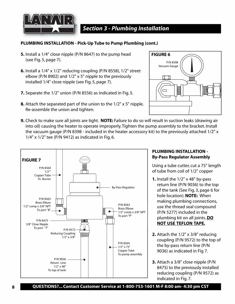
PLUMBING INSTALLATION - Pick-Up Tube to Pump Plumbing (cont.)
5. Install a 1/4" close nipple (P/N 8647) to the pump head (see Fig. 5, page 7).
6. Install a 1/4" x 1/2" reducing coupling (P/N 8558), 1/2" streetelbow (P/N 8902) and 1/2" x 5" nipple to the previouslyinstalled 1/4" close nipple (see Fig. 5, page 7).
7. Separate the 1/2" union (P/N 8556) as indicated in Fig. 5.
8. Attach the separated part of the union to the 1/2" x 5" nipple.Re-assemble the union and tighten.
9. Check to make sure all joints are tight. NOTE: Failure to do so will result in suction leaks (drawing airinto oil) causing the heater to operate improperly. Tighten the pump assembly to the bracket. Installthe vacuum gauge (P/N 8398 - included in the heater accessory kit) to the previously attached 1/2" x1/4" x 1/2" tee (P/N 9412) as indicated in Fig. 6.
P/N 8398Vacuum Gauge
PLUMBING INSTALLATION - By-Pass Regulator Assembly
Using a tube cutter, cut a 75" length of tube from coil of 1/2" copper
1. Install the 1/2" x 48" by-passreturn line (P/N 9036) to the topof the tank (See Fig. 3, page 6 forhole location). NOTE: Whenmaking plumbing connections,use the thread seal compound(P/N 5277) included in theplumbing kit on all joints. DONOT USE TEFLON TAPE.
2. Attach the 1/2" x 3/8" reducingcoupling (P/N 9572) to the top ofthe by-pass return line (P/N9036) as indicated in Fig 7.
3. Attach a 3/8" close nipple (P/N8475) to the previously installedreducing coupling (P/N 9572) asindicated in Fig. 7.
FIGURE 7
FIGURE 6
P/N 8563 Brass Elbow
1/2" comp x 3/8" NPTTo port "B"
P/N 85641/2""
Copper TubeTo Burner
P/N 8563 Brass Elbow1/2" comp x 3/8" NPTTo port "P"
By-Pass Regulator
P/N 8564 1/2" x 75"Copper TubeTo pump assembly
P/N 84753/8" Close Nipple
To port "T"P/N 9572
Reducing Coupling1/2" x 3/8"
P/N 9036 Return Line
1/2" x 48"To top of tank

Visit our website at: www.lanair.com 9
Section 3 - Plumbing Installation
PLUMBING INSTALLATION - By-Pass Regulator Assembly (cont.)
4. Install a 1/2" comp x 3/8" NPT brass elbow (P/N 8563) intothe port labeled "B" on the bottom of the by-pass regula-tor (see Figs. 7 & 8). NOTE: The elbow should be facing up.
5. Install a 1/2" comp x 3/8" NPT brass elbow (P/N 8563) intothe port labeled "P" on the bottom of the by-pass regula-tor (see Figs. 7 & 8). NOTE: The elbow should be facingdown.
6. Attach the by-pass regulator assembly (T) to the top of thereturn line assembly (see Fig. 7) and tighten. NOTE: Thebrass elbow (P/N 8114) facing up should face the front ofthe tank and the return line MUST drop straight into thetank. DO NOT MODIFY OR ADD ELBOWS.
7. Install a 1/8" close nipple (P/N 8882) into the pump head outlet as indicated in Fig. 9.
8. Attach a 1/8" x 3/8 " reducing coupling (P/N 8560) and 1/2" comp x 3/8" NPT brass elbow to the 1/8"close nipple (see Fig. 9).
9. Install the 1/2" copper tube (P/N 8564) between the compression fitting of the pump assembly andthe compression fitting on the by-pass regulator (see Figs. 7 & 9).
FIGURE 8
Bottom of By-Pass Regulator
P/N 8560Reducing Coupling 3/8" x 1/8"
P/N 8563Brass Elbow
1/2" comp x 3/8" NPT
P/N 8564Copper Tube 1/2" x 75"
To By-pass Regulator
P/N 88821/8" Close Nipple
PUMP ASSEMBLYPUMP HEAD
FIGURE 9

® Section 3 - Plumbing Installation
QUESTIONS?... Contact Customer Service at 1-800-753-1601 M-F 8:00 am- 4:30 pm CST10
1/2" Copper TubeTo By-pass
Regulator
P/N 8850Brass Elbow
1/2" comp x 1/4NPT
FIGURE 10 PLUMBING INSTALLATION - By-Pass Regulator To Burner
1. Attach the 1/2" comp x 1/4" NPT brass elbow (P/N8850) as indicated in Fig 10.
3. Install the remaining 1/2" copper tube betweenthe compression fittings of the by-pass regulatorand burner (see Figs. 7 & 10).NOTE: Make sure all fittings are properly tight-ened. Leaking fittings may cause delayed ignitionin the burner.
Tank Drain and Plug
1. Determine which side of the tank the drain will be on. On that side, install a 1/2" close nipple (P/N 8186) to the drain hole (see Fig 11).
2. Install the 1/2" brass ball valve (P/N 8187) to the 1/2" close nipple. Install a 1/2" pipe plug (P/N 8185)into the end of the ball valve (see Fig. 11).
3. Install a 1/2" pipe plug (P/N 8185) into the hole on the opposite side of the tank (see Fig.12).
4. Vent the tank in accordance to state and local codes.
FIGURE 11
FIGURE 12
P/N 81861/2" Close Nipple
P/N 81871/2" Brass Ball
Valve
P/N 8185 1/2" Pipe Plug P/N 8185
1/2" Pipe Plug
Visit our website at: www.lanair.com 11
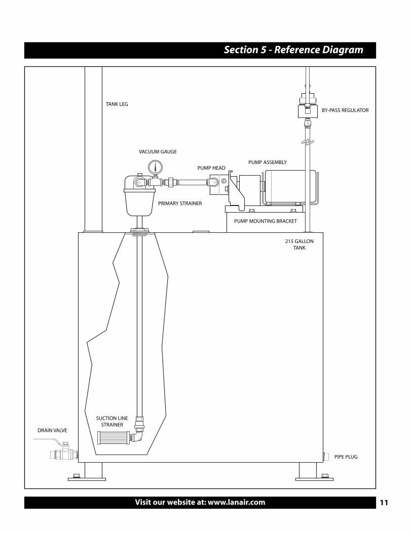
Section 5 - Reference Diagram
PUMP ASSEMBLY
BY-PASS REGULATOR
PRIMARY STRAINER
PUMP MOUNTING BRACKET
PUMP HEAD
VACUUM GAUGE
TANK LEG
SUCTION LINESTRAINER
215 GALLONTANK
DRAIN VALVE
PIPE PLUG

© 2009 Lanair Products LLCLanair is a registered trademark of Lanair Products LLC
Part # 5320REV.15
10-05-2009
Lanair Products LLC4109 Capital Circle
Janesville, Wisconsin 535461-888-370-6531www.lanair.com