212cc ohv horizontal gas engine - northern tool · 2019-05-01 · warning: 212cc ohv horizontal gas...
TRANSCRIPT
212cc OHV Horizontal Gas Engine
Owner’s Manual
WARNING: Read carefully and understand all ASSEMBLY AND OPERATION
INSTRUCTIONS before operating. Failure to follow the safety rules and other basic safety
precautions may result in serious personal injury.
SAVE THESE INSTRUCTIONS

Page 2 of 35
Thank you very much for choosing a Powerhorse
® product!
For future reference, please complete the owner’s record below:
Serial Number/Lot Date Code:
Purchase Date: _
Save the receipt, warranty, and this manual. It is important that you read
the entire manual to become familiar with this product before you begin
using it.
This engine is designed for certain applications only. Northern Tool &
Equipment is not responsible for issues arising from modification or
improper use of this product such as an application for which it was not
designed. We strongly recommend that this product not be modified
and/or used for any application other than that for which it was designed.
For technical questions, please call 1-866-443-2576.
Page 3 of 35
Technical Specifications ...................................................................................................................... 4
Important Safety Information ............................................................................................................... 4
Specific Operation Warnings ............................................................................................................... 6
Safety Labels ......................................................................................................................................... 8
Main Engine Parts ................................................................................................................................. 9
Before Each Use .................................................................................................................................. 10
Operating Instructions ........................................................................................................................ 11
Maintenance ........................................................................................................................................ 16
Troubleshooting .................................................................................................................................. 24
Storage ................................................................................................................................................. 24
Parts Diagram ...................................................................................................................................... 26
Parts List .............................................................................................................................................. 27
Replacement Parts .............................................................................................................................. 28
Table of Contents

Page 4 of 35
Property Specification Model DH212 Displacement 212 cc Bore 2.76 inches Stroke 2.17 inches Oil Capacity 0.16 gal. (0.6L) Net Weight 34.71 lbs.
WARNING
We do not approve or authorize the use of these engines on 3-wheel All-Terrain Vehicles (ATVs),
motor bikes, fun/recreational go-karts, aircraft products or vehicles intended for use in competitive
events. Use of these engines in such applications could result in property damage, serious injury
(including paralysis), or even death.
WARNING
The engine exhaust from this product contains chemicals known to the State of California to cause
cancer, birth defects, or other reproductive harm.
Technical Specifications
Important Safety Information
SAFETY REFERENCES
The safety alert symbol is used to identify safety information about hazards that can result in
personal injury. A signal word (DANGER, WARNING, or CAUTION) is used with the alert symbol to
indicate the likelihood and the potential severity of injury. In addition, a hazard symbol maybe used to
represent the type of hazard.
DANGER: indicates a hazard which, if not avoided, will result in death or serious injury.
WARNING: indicates a hazard which, if not avoided, could result in death or serious injury.
CAUTION: indicates a hazard which, if not avoided, might result in minor or moderate injury.
CAUTION: when used without the alert symbol, indicates a situation that could result in
damage to the engine.
This manual contains safety information to make you aware of the hazards and risks
associated with engines, and how to avoid them. Because we do not necessarily
know what equipment this engine will power, it is important that you read and
understand these instructions and the instructions for the equipment this engine
powers.

Page 5 of 35
WARNING
WORK AREA SAFETY
• Inspect the work area before each use. Keep work area clean, dry, free of clutter, and well-lit.
Cluttered, wet, or dark work areas can result in injury. Using the engine in confined work areas
may put you dangerously close to other cutting tools and rotating parts.
• Do not allow the engine to come into contact with an electrical source. The engine is not insulated
and contact will cause electrical shock.
• Keep children and bystanders away from the work area while operating the tool. Do not allow
children to handle the engine.
• Be aware of all power lines, electrical circuits, water pipes, and other mechanical hazards in your
work area. Some of these hazards may be hidden from your view and may cause personal injury
and/or property damage if contacted.
WARNING
PERSONAL SAFETY
• Stay alert, watch what you are doing, and use common sense when operating the engine. Do not
use the engine while you are tired or under the influence of drugs, alcohol, or medication. A
moment of inattention while operating the tool may result in serious personal injury.
• Dress properly. Do not wear loose clothing, dangling objects, or jewelry. Keep your hair, clothing
and gloves away from moving parts. Loose clothes, jewelry, or long hair can be caught in moving
parts. Air vents on the tool often cover moving parts and should be avoided.
• Wear the proper personal protective equipment when necessary. Use ANSIZ87.1 compliant safety
goggles (not safety glasses) with side shields, or when needed, a face shield. Use a dust mask in
dusty work conditions. Also use non-skid safety shoes, hardhat, gloves, dust collection systems,
and hearing protection when appropriate. This applies to all persons in the work area.
• Do not overreach. Keep proper footing and balance at all times.
• Remove keys or wrenches before connecting the tool to an air supply, power supply, or turning on
the tool. A wrench or key that is left attached to a rotating part of the tool may cause personal
injury.
• Secure the work with clamps or a vise instead of your hand when practical. This safety precaution
allows for proper tool operation using both hands.
CAUTION
ENGINE USE AND CARE
• This engine is shipped from us without oil. If you start the engine without oil, the engine will be
damaged beyond repair and will not be covered under warranty.
• Do not force the engine. Products are safer and do a better job when used in the manner for which
they are designed. Plan your work and use the correct product for the job.
• Check for damaged parts before each use. Carefully check that the engine will operate properly

Page 6 of 35
WARNING
Gasoline and its vapors are extremely flammable and explosive.
Fire or an explosion can cause severe burns or death.
When Adding Fuel
• Turn engine 'off' and let it cool at least 2 minutes before removing the fuel filler cap.
• Fill the fuel tank outdoors or in a well-ventilated area.
• Do not overfill the fuel tank.
• Keep gasoline away from sparks, open flames, pilot lights, heat, and other ignition sources.
• Check the fuel lines, the tank, the cap, and the fittings frequently for cracks or leaks. Replace if
necessary.
When Starting the Engine
• Make sure the spark plug, muffler, fuel filler cap, and air cleaner are in place.
• Do not crank the engine with the spark plug removed.
• If fuel spills, wait until it evaporates before starting the engine.
• If the engine floods, set the choke to the 'open/run' position, place throttle in 'fast', and crank
until the engine starts.
When Operating Equipment
• Do not choke the carburetor to stop the engine.
When Transporting Equipment
• Transport with the fuel tank EMPTY.
When Storing Gasoline or Equipment with Fuel in the Tank
• Store away from furnaces, stoves, water heaters, or other appliances that have a pilot light or
other ignition source because they can ignite gasoline vapors.
WARNING
Starting the engine creates sparking.
Sparking can ignite nearby flammable gases.
Explosion and fire could result.
• If there is a natural or LP gas leakage in the area, do not start the engine.
• Do not use pressurized starting fluids because vapors are flammable.
and perform its intended function. Replace damaged or worn parts immediately. Never operate the
engine with a damaged part.
Specific Operation Warnings

Page 7 of 35
WARNING
• Rapid retraction of starter cord (kickback) will pull hand and arm toward engine faster than you
can let go. Broken bones, fractures, bruises or sprains could result.
• When starting engine, pull cord slowly until resistance is felt, then pull rapidly.
• Direct coupled equipment components such as, but not limited to, blades, impellers, pulleys,
sprockets, etc., must be securely attached.
WARNING
• Rotating parts can contact or entangle hands, feet, hair, clothing, or accessories.
• Traumatic amputation or severe laceration can result.
• Operate the equipment with guards in place. Keep hands and feet away from rotating parts.
• Tie up long hair and remove jewelry.
• Do not wear loose-fitting clothing, dangling drawstrings, or items that could become caught.
WARNING
• Engines give off carbon monoxide, an odorless, colorless, poison gas.
• Breathing carbon monoxide can cause nausea, fainting or death.
• Start and run the engine outdoors.
• Do not start or run engine in an enclosed area, even if doors or windows are open.
WARNING
• Running engines produce heat. Engine parts, especially mufflers, become extremely hot.
• Severe thermal burns can occur on contact.
• Combustible debris, such as leaves, grass, brush, etc., can catch fire.
• Allow muffler, engine cylinder and fins to cool before touching.
• Remove accumulated debris from muffler area and cylinder area.
• Install and maintain in working order a spark arrester before using equipment on forest-covered,
grass-covered, brush-covered unimproved land. The state of California requires this. Other
states may have similar laws. Federal laws apply on federal land.
Page 8 of 35
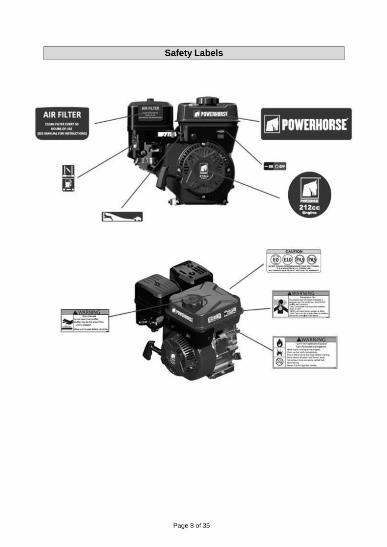
Safety Labels

Page 9 of 35
Reference Subassembly
A Air Cleaner
B Muffler
C Spark Plug
D Throttle Lever
E Recoil Starter
F Starting Handle
G Fuel Shut-off
H Choke Lever
I Fuel Filler Cap
J Fuel Tank
K Oil Dipstick
L Drain Plug
M Engine Switch
Main Engine Parts

Page 10 of 35
⚠WARNING
Improperly maintaining this engine, or failure to correct a problem before operation, can cause a
malfunction in which you can be seriously hurt or killed. Always perform a pre-operation inspection
before each operation, and correct any problem.
Pre-Operation Checks
For your safety, and to maximize the service life of your equipment, it is very important to take a few
moments before you operate the engine to check its condition. Be sure to take care of any problem
you find, or have your servicing dealer correct it, before you operate the engine.
Before beginning your pre-operation checks, be sure the engine is level and the engine switch is in
the OFF position. Always check the following items before you start the engine:
Check the General Condition of the Engine
1. Look around and underneath the engine for signs of oil or gasoline leaks.
2. Remove any excessive dirt or debris, especially around the muffler and recoil starter.
3.Look for signs of damage.
4.Check that all shields and covers are in place, and all nuts, bolts, and screws are tightened.
Check the Engine
1.Check the fuel level. Starting with a full tank will help to eliminate or reduce operating interruptions for refueling.
2.Check the engine oil level. Running the engine with a low oil level can cause engine damage.
The Oil Alert system will automatically stop the engine before the oil level falls below safe limits. However, to avoid the inconvenience of an unexpected shutdown, always check the engine oil level before startup.
3. Check the air filter element. A dirty air filter element will restrict air flow to the carburetor, reducing engine performance.
4.Check the equipment powered by this engine.
Review the instructions provided with the equipment powered by this engine for any precautions and procedures that should be followed before engine start-up.
Before Each Use

Page 11 of 35
⚠WARNING
• Gasoline and its vapors are extremely flammable and explosive.
• Fire or explosion can cause severe burns or death.
• Engines give off carbon monoxide, an odorless colorless, poison gas. Breathing carbon
monoxide can cause nausea, fainting or death.
• Unintentional sparking can result in fire or electric shock.
• Unintentional start-up can result in entanglement, traumatic amputation, or laceration.
⚠CAUTION
HIGH ALTITUDE OPERATION
Operating at an altitude of greater than 2000 feet (610 meters) may affect your engines performance,
fuel consumption, and emissions. To remain emissions compliant and improve engine performance
at higher altitudes, a high-altitude kit is required. A high altitude kit includes a carburetor jet resized
to help correct air / fuel mixture at altitude. To order a high altitude kit or if you have additional
questions, go to www.northerntool.com or contact us at 1-866-443-2576. Please note, engines with
the high-altitude kit installed operated at lower altitudes could cause severe engine damage and
affect emissions compliance. When modified, a tag or decal should be added to the product stating
that a high-altitude kit was installed and to remind you to re-service the carburetor (re-jet) when
operating in lower altitude environments.
Starting the Engine
1. Move the fuel shut-off to the ON position.
Operating Instructions

Page 12 of 35
2. To start a cold engine, move the choke lever to the CHOKE position.
To restart a warm engine, leave the choke lever in the RUN position.
3. Move the throttle lever away from the MIN. position, about 1/3 of the way toward the MAX.
position.

Page 13 of 35
4. Turn the engine switch to the ON position.
5. Operate the starter.
Recoil Start
Pull the starter grip lightly until you feel resistance, then pull briskly in the direction of the arrow as
shown below. Return the starter grip gently.
⚠WARNING
Do not allow the starter grip to snap back against the engine. Return it gently to prevent damage to
the starter.
Electric Starter
Turn the key to the START position, and hold it there until the engine starts. If the engine fails to start
within 5 seconds, release the key, and wait at least 10 seconds before operating the starter again.

Page 14 of 35
When the engine starts, release the key, allowing it to return
to the ON position.
⚠WARNING
Using the electric starter for more than 5 seconds at a time will overheat the starter motor and can
damage it.
6. If the choke lever has been moved to the CHOKE position to start the engine, gradually move it to
the RUN position as the engine warms up.
Stopping the Engine
To stop the engine in an emergency, simply turn the engine switch to the OFF position. Under normal
conditions, use the following procedure. Refer to the instructions provided by the equipment
manufacturer.
Page 15 of 35
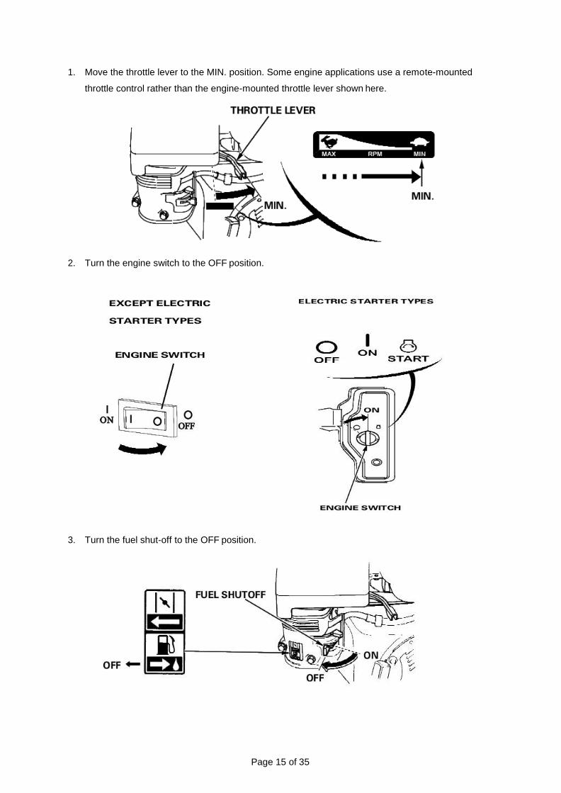
1. Move the throttle lever to the MIN. position. Some engine applications use a remote-mounted
throttle control rather than the engine-mounted throttle lever shown here.
2. Turn the engine switch to the OFF position.
3. Turn the fuel shut-off to the OFF position.

Page 16 of 35
Setting Engine Speed
Position the throttle lever for the desired engine speed. Some engine applications use a remote-
mounted throttle control rather than the engine-mounted throttle lever shown here. Refer to the
instructions provided by the equipment manufacturer. For engine speed recommendations, refer to
the instructions provided with the equipment powered by this engine.
⚠WARNING
All the components used to build this engine must remain in place for proper operation.
Use only original equipment replacement parts. Other parts may not perform as well,
may damage the unit, and may result in injury.
In addition, use of other parts may void your warranty. We recommend that you use an authorized
service center for all maintenance and service of the engine and engine parts.
Before performing adjustments or repairs
Disconnect the spark plug wire and keep it away from the spark plug.
• Use only correct tools.
• Do not tamper with governor spring, links or other parts to increase engine speed.
• Replacement parts must be the same and installed in the same position as the original parts.
• Do not strike the flywheel with a hammer or hard object because the flywheel may later
shatter during operation.
When Testing for Spark
Use an approved spark plug tester.
Maintenance Schedule
REGULAR SERVICE PERIOD (3)
Perform at every indicated month or
operating hour interval, whichever comes
first.
Each
Use
First
Month or
20 Hrs
Every 3
Months or
50 Hrs
Every 6
Months or
100 Hrs
Every
Year or 300
Hrs
Item
Engine Oil
Check level ○
Change ○ ○
Check ○
Maintenance

Page 17 of 35
Air Cleaner
Clean ○(1) ○(1)
Replace ○
Sediment Cup Clean ○
Spark Plug
Check-adjust ○
Replace ○
Spark Arrester Clean ○
Idle Speed Check-adjust ○(2)
Valve Clearance Check-adjust ○(2)
Combustion Chamber Clean After every 500 Hrs.(2)
Fuel Tank & Filter Clean ○(2)
Fuel Tube Check Every 2 years (Replace if necessary) (2)
Note:
(1) Service more frequently when used in dusty areas.
(2) We recommend that you see an authorized service center for all maintenance and service of the
engine and engine parts. Use only our genuine parts.
(3) For commercial use, log hours of operation to determine proper maintenance intervals.
Engine Oil
Oil is a major factor affecting performance and service life. Use 4-stroke automotive detergent oil.
Recommended Oil
Use 4-stroke motor oil that meets or exceeds the requirements for API service category SJ or later (or
equivalent). Always check the API service label on the oil container to be sure it includes the letters
SJ or later (or equivalent).
SAE 10W-30 is recommended for general use. Other viscosities shown in the chart may be used
when the average temperature in your area is within the indicated range.

Page 18 of 35
Before Adding or Checking Oil
• Place engine on a level surface.
• Clean the oil fill area for any debris.
How to Check/Add Oil
⚠WARNING
Gasoline is highly flammable and explosive. You can be burned or seriously injured when
refueling.
• Stop engine and keep heat, sparks, and flames away.
• Refuel only outdoors.
• Wipe up spills immediately.
1. Remove the oil dipstick and wipe with a clean cloth. 2. Insert the oil dipstick into the filler neck without screwing it in.
3. Remove the oil dipstick and check the oil level. Make sure the oil is at the FULL mark on the dipstick.
4. If the oil level is near or below the lower limit mark on the dipstick, fill with the recommended oil. Do not overfill. After adding oil, wait one minute and then recheck the oil level.
5. Replace and tighten the oil dipstick.
Fuel Recommendations
Unleaded gasoline: U.S. Pump octane rating 86 or higher, except U.S. Research octane rating 91 or
higher. Pump octane rating 86 or higher. This engine is certified to operate on unleaded gasoline with
a pump octane rating of 86 or higher (a research octane rating of 91 or higher).
Refuel in a well-ventilated area with the engine stopped. If the engine has been running, allow it to
cool first. Never refuel the engine inside a building where gasoline fumes may reach flames or sparks.

Page 19 of 35
You may use unleaded gasoline containing no more than 10% ethanol (E10) or 5% methanol by
volume. In addition, methanol must contain co solvents and corrosion inhibitors. Use of fuels with
content of ethanol or methanol greater than shown above may cause starting and/or performance
problems. It may also damage metal, rubber, and plastic parts of the fuel system. Engine damage or
performance problems that result from using a fuel with percentages of ethanol or methanol greater
than shown above are not covered under warranty.
How to Add Fuel
⚠WARNING
Gasoline and its vapors are extremely flammable and explosive. Fire or explosion can cause severe
burns or death.
For refueling, refer to the manufacturer’s instructions provided with the equipment. See the following
for a Powerhorse supplied standard fuel tank refueling instruction
1. With the engine stopped and on a level surface, remove the fuel filler cap and check the fuel level.
Refill the tank if the fuel level is low.
2. Add fuel to the bottom of the maximum fuel level limit of the fuel tank. Do not overfill. Wipe up
spilled fuel before starting the engine.

Page 20 of 35
Carburetor Adjustment
Never make adjustments to the carburetor. The carburetor was set at the factory to operate efficiently
under most conditions. However, if adjustments are required, see any our Authorized Dealer for
service.
⚠CAUTION
The manufacturer of the equipment on which this engine is installed specifies the top speed at which
the engine will be operated. Do not exceed this speed.
How to Replace the Spark Plug
If the engine has been running, let it cool before servicing
the spark plug. For good performance, the spark plug
must be properly gapped and free of deposits.
1. Disconnect the spark plug cap, and remove any
dirt from around the spark plug area.
2. Remove the spark plug with a 13/16-inch spark
plug wrench.
3. Visually inspect the spark plug. Replace it if
damaged or badly fouled, if the sealing washer
is in poor condition, or if the electrode is worn.
4. Measure the spark plug electrode gap with a
wire-type feeler gauge. Correct the gap, if
necessary, by carefully bending the side electrode.
The gap should be: 0.7-0.8 mm (0.028-0.031 in).
5. Install the spark plug carefully, by hand, to
avoid cross-threading.
6. After the spark plug is seated, tighten with a
13/16-inch spark plug wrench to compress the
sealing washer.
When installing a new spark plug, tighten 1/2 turn after the spark plug seats to compress the
washer.
When reinstalling the original spark plug, tighten 1/8 1/4 turn after the spark plug seats to
compress the washer.
⚠CAUTION
A loose spark plug can overheat and damage the engine. Over tightening the spark plug can damage
the threads in the cylinder head.
7. Attach the spark plug cap to the spark plug.
Page 21 of 35
Inspect Muffler and Spark Arrester
⚠WARNING
Running engines produce heat. Engine parts, especially muffler, become extremely hot. Severe
thermal burns can occur on contact. Combustible debris, such as leaves, grass, brush, etc. can
catch fire.
1. Allow muffler, engine cylinder, and fins to cool before touching.
2. Remove accumulated debris from muffler area and cylinder area.
3. Replacement parts must be the same and installed in the same position as the original parts or
fire could result.
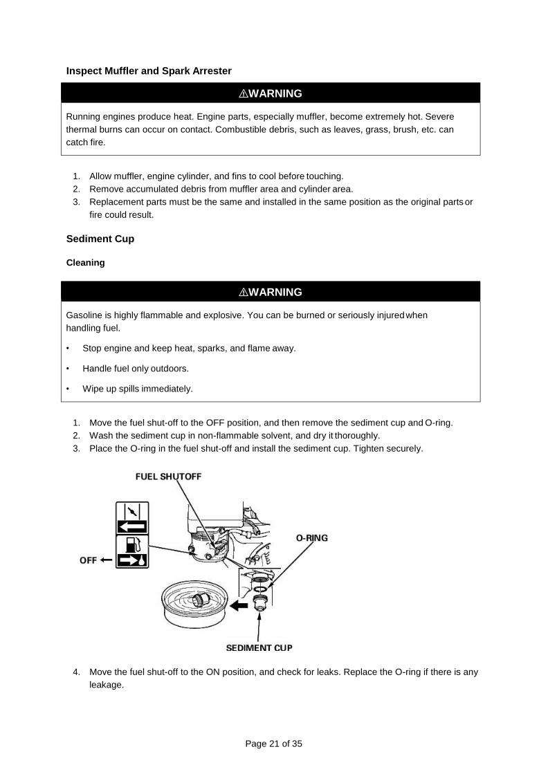
Sediment Cup
Cleaning
⚠WARNING
Gasoline is highly flammable and explosive. You can be burned or seriously injured when
handling fuel.
• Stop engine and keep heat, sparks, and flame away.
• Handle fuel only outdoors.
• Wipe up spills immediately.
1. Move the fuel shut-off to the OFF position, and then remove the sediment cup and O-ring.
2. Wash the sediment cup in non-flammable solvent, and dry it thoroughly.
3. Place the O-ring in the fuel shut-off and install the sediment cup. Tighten securely.
4. Move the fuel shut-off to the ON position, and check for leaks. Replace the O-ring if there is any
leakage.
Page 22 of 35
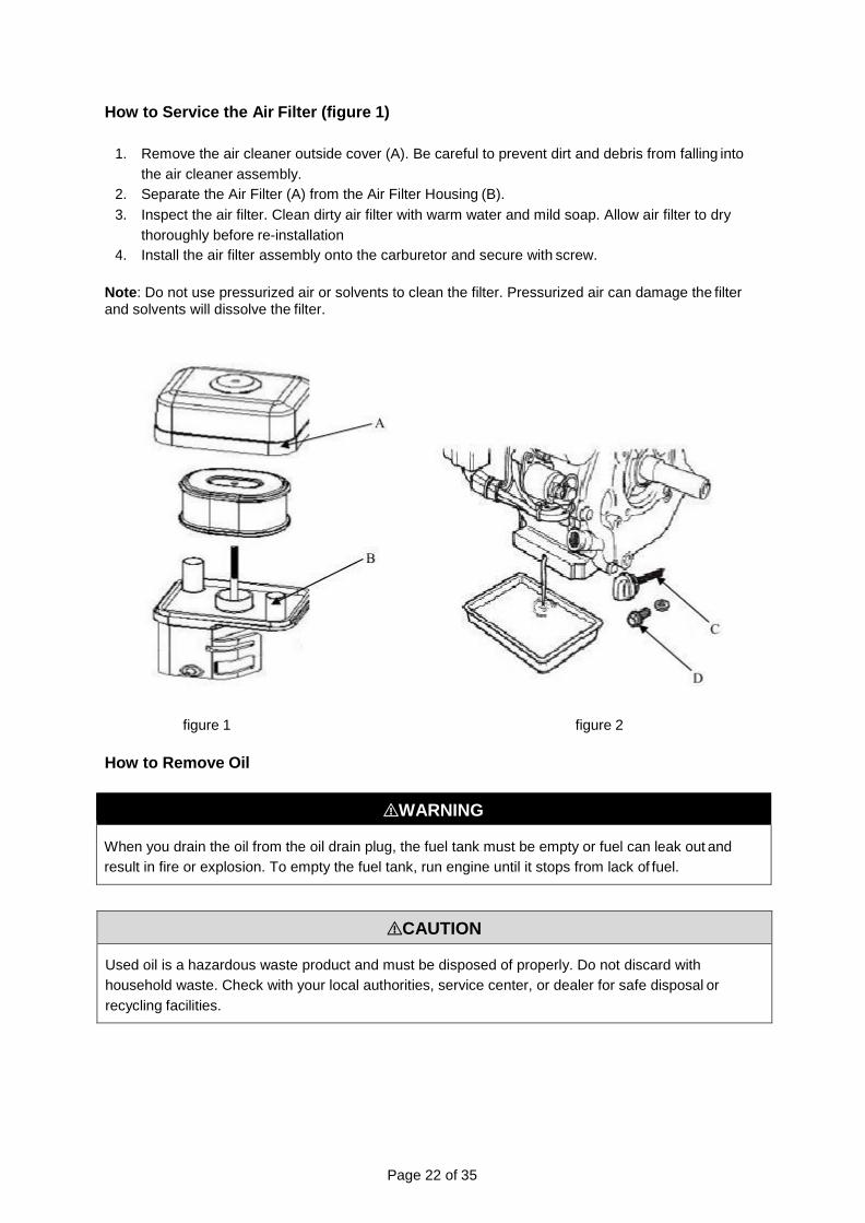
How to Service the Air Filter (figure 1)
1. Remove the air cleaner outside cover (A). Be careful to prevent dirt and debris from falling into
the air cleaner assembly.
2. Separate the Air Filter (A) from the Air Filter Housing (B).
3. Inspect the air filter. Clean dirty air filter with warm water and mild soap. Allow air filter to dry
thoroughly before re-installation
4. Install the air filter assembly onto the carburetor and secure with screw.
Note: Do not use pressurized air or solvents to clean the filter. Pressurized air can damage the filter and solvents will dissolve the filter.
figure 1 figure 2
How to Remove Oil
⚠WARNING
When you drain the oil from the oil drain plug, the fuel tank must be empty or fuel can leak out and
result in fire or explosion. To empty the fuel tank, run engine until it stops from lack of fuel.
⚠CAUTION
Used oil is a hazardous waste product and must be disposed of properly. Do not discard with
household waste. Check with your local authorities, service center, or dealer for safe disposal or
recycling facilities.
Page 23 of 35
Removing Oil The oil must be drained from the Oil Drain Plug (figure 2).
1. Remove the dipstick (C)
2. Please an approved container below the oil drain plug.
3. Remove the Oil drain plug (D) and allow oil to the drain into the approved container.
4. Install Oil drain plug (D) and wrench tighten.
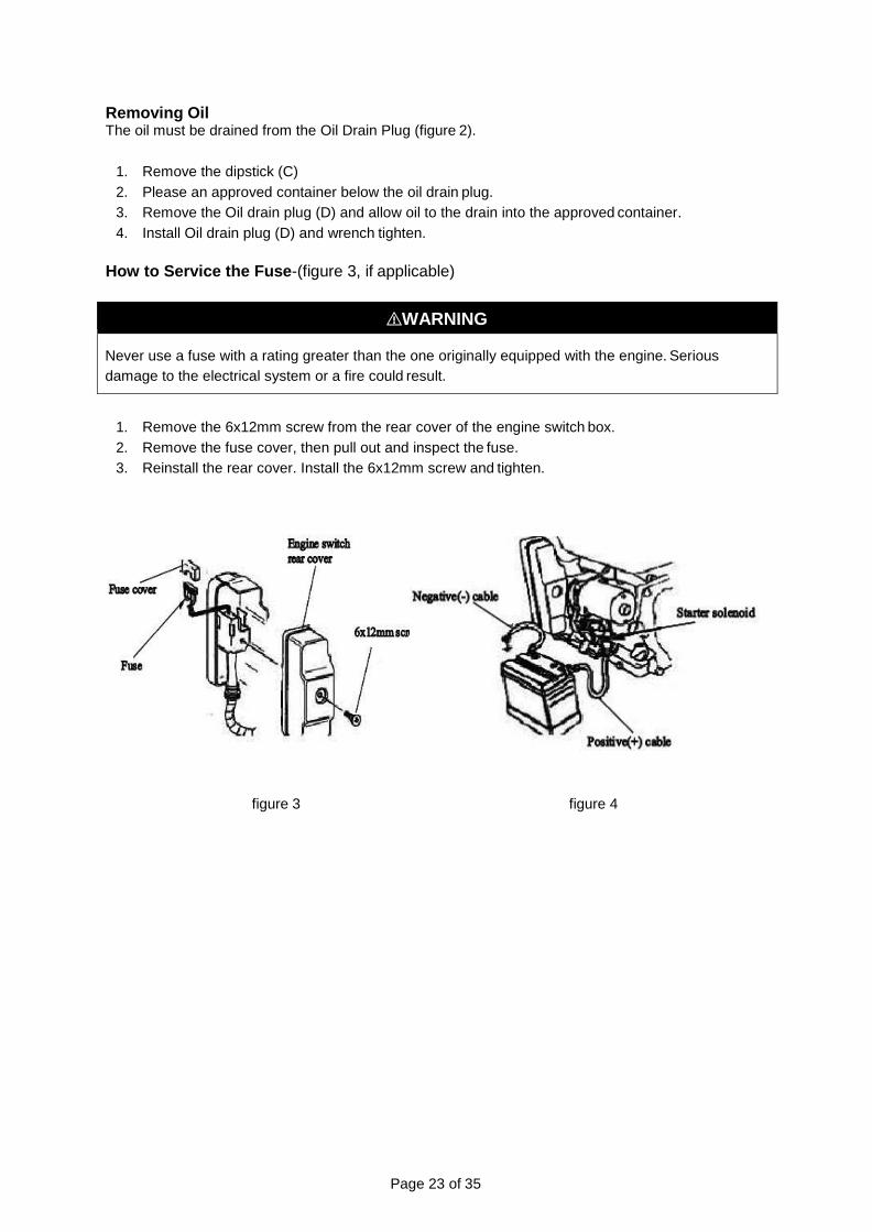
How to Service the Fuse-(figure 3, if applicable)
⚠WARNING
Never use a fuse with a rating greater than the one originally equipped with the engine. Serious
damage to the electrical system or a fire could result.
1. Remove the 6x12mm screw from the rear cover of the engine switch box.
2. Remove the fuse cover, then pull out and inspect the fuse.
3. Reinstall the rear cover. Install the 6x12mm screw and tighten.
figure 3 figure 4

Page 24 of 35
How to Service the Battery (figure 4, if applicable)
⚠WARNING
Be careful not to connect the battery in reverse polarity, as this will short circuit the battery
charging system.
Note: Use a 12-volt battery with an ampere-hour rating of at least 18 Ah.
1. Connect the positive (+) cable to the starter solenoid terminal. 2. Connect the negative (-) cable to an engine mounting bolt or other good engine ground
connection. 3. Connect the positive (+) cable to the positive (+) terminal. 4. Connect the negative (-) cable to the negative (-) terminal.
Failure Possible Cause Corrective Action
If engine will not start.
Out of fuel. If engine is cold, ensure choke lever is set correctly. Add fuel.
Engine flooded. Set choke lever to open/run position.
Dirty or faulty spark plug/engine fails to product spark.
Remove spark plug and clean it. Check the
spacing on the electrode and set the gap to
the correct dimension. See Maintenance
section. If plug is damaged, replace with a
new spark plug.
Ensure the spark plug is installed and wire
is connected.
⚠WARNING
When storing fuel or equipment with fuel in tank:
Store away from furnaces, stoves, water heaters, or other appliances that have a pilot light or other
ignition source because they can ignite vapors.
When transporting equipment:
Transport with fuel tank EMPTY or with fuel shut-off valve OFF.
Troubleshooting
⚠WARNING
Do not crank engine with spark plug removed.
Storage

Page 25 of 35
The following precautions should be taken if storing your engine for a period exceeding 30 days, or for
seasonal storage.
• While engine is still warm, change oil.
• Clean engine of surface debris, chaff or grass.
• Drain all fuel from fuel tank into proper receptacle for storage.
• Remove spark plug. Place 1 teaspoon or 5 ml. of oil into spark plug hole.
• Pull starter rope slowly 8-10 times to properly coat the cylinder bore and piston for storage.
• Replace spark plug and tighten. Any residual oil may burn off in subsequent starts. This may
result in white smoke emission from muffler.
Note: Storing or transporting with the spark plug down will result in hard starting and/or engine smoking.
• Store in a clean dry area.
• When removing unit from storage, only use fresh gasoline. Perform operation checks (see
maintenance schedule) before starting engine.
** Engine power will decrease 3.5% for each 1,000 feet (300 meters) above sea level and 1% for each
10°F (5.6°C) above 77°F (25°C). The engine will operate satisfactorily at an angle up to 15°. Refer to
the equipment operator’s manual for safe allowable operating limits on slopes.
We recommend that you see an authorized service center for all maintenance and service of the
engine and engine parts. Use only our genuine parts.
Page 26 of 35
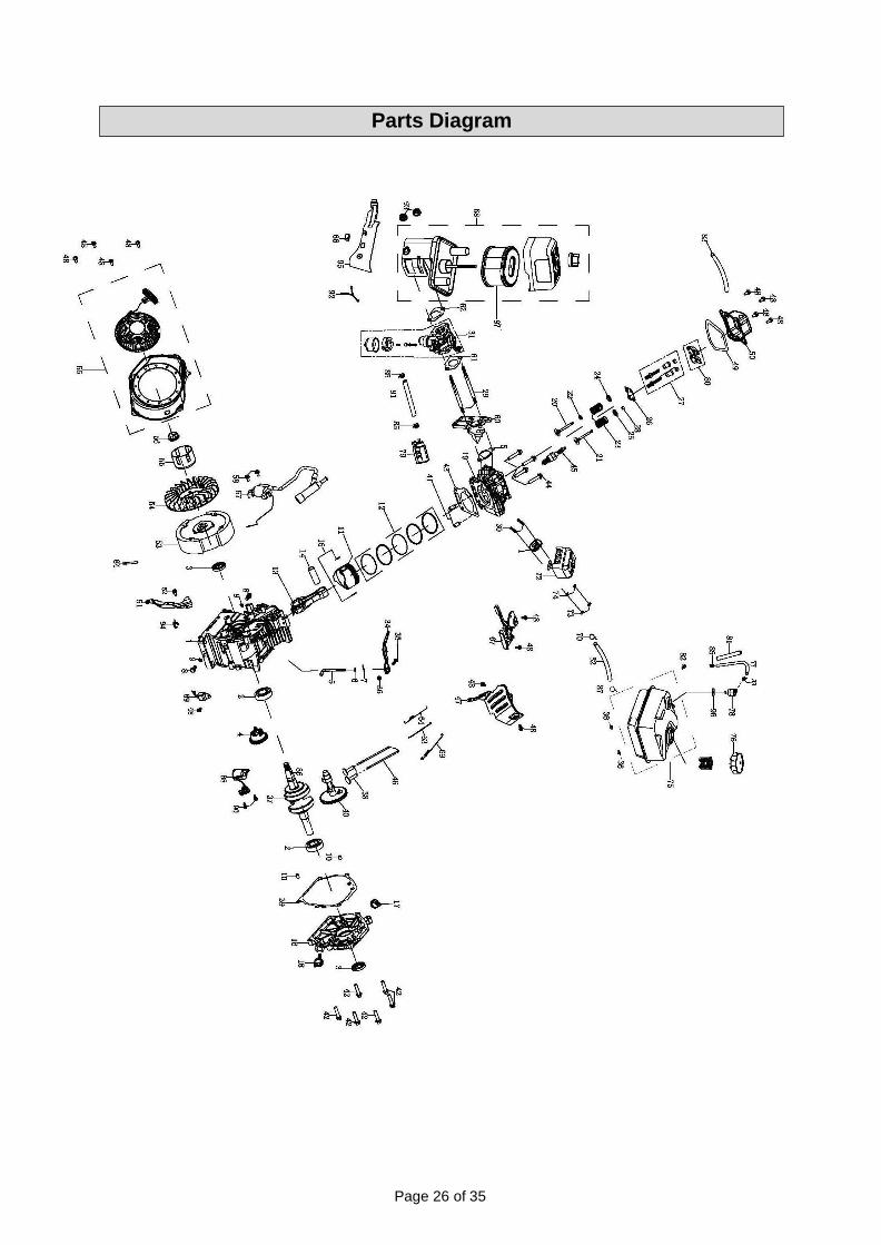
Parts Diagram

Page 27 of 35
Ref Code Part Description Qty Ref Code Part Description Qty
1 240210 CRANKCASE 1 50 241104 COVER COMP,
CYLINDER HEAD 1
2 93009 BALL BEARING 2 51 245702 WIND SHIELD COMP. 1
3 93507 OIL SEAL 2 52 91330 BOLT M6X20 1
4 244302 GOVERNOR ASSEMBLY 1 53 240401 FLYWHEEL ASSEMBLY 1
5 243901 SHAFT, GOVERNOR ARM 1 54 244601 FAN, RECOIL
STARTER 1
6 96804 WASHER, GOVERNOR ARM SHAFT 1 55 244502 PULLEY,STARTER 1
7 243902 PIN,LOCK 1 56 90003 NUT 1
8 91816 BOLT, DRAIN PLUG 2 57 97514 IGNITION COIL ASSY 1
9 94007 WASHER, DRAIN PLUG 2 58 91331 BOLT M6X25 2
10 240901 DOWEL PIN, CASECOVER 2 59 96047 PACKING, INTAKE 1
11 241208 PISTON 1 60 242301 INSULATOR,
CARBURETOR 1
12 241606 SCRAPER RING SET, PISTON 1 61 96051 PACKING,CARBURETO
R 1
13 241503 ROD ASSEMBLY, CONNECTING 1 62 94226 GANGDIAN 1
14 245503 PIN, PISTON 1 63 242701 ROD, GOVERNOR 1
15 241301 CLIP, PISTON 2 64 244201 SPRING, THROTTLE
RETURN 1
16 240105 COVER ASSEMBLY, CRANKCASE 1 65 244740-048 RECOIL STARTER
ASSEMBLY 1
17 241401-276 OIL PLUG 1 66 536001 SWITCH ASSEMBLY 1
18 245601-276 DIPSTICK 1 67 244403 SHROUD ASSY,
UPPER 1
19 241011 CYLINDER HEAD 1 68 242933 AIR CLEANER
ASSEMBLY 1
20 241704 VALVE, IN 1 69 244103 SPRING, GOVERNOR 1
21 245905 VALVE EXHAUST 1 70 94403 CLIP, FUEL LINE 1
22 241806 RETURNER, INTAKE VALVE 1 71 96054 PACKING, EXHAUST 1
23 246001 SPRING, VALVE 2 72 243752 MUFFLER COMP 1
24 241801 SEAT, VALVE SPRING, IN 1 73 90011 NUT M8 2
25 241802 SEAT, VALVE SPRING, EX 1 74 94206 SPRING WASHER 2
26 242202 PLATE, PUSH ROD GUIDE 1 75 243135-048 FUEL TANK ASSEMBLY
1
27 91818 ROCKER ARM TIGHTENINIG BOLTS 2 76 243609 THE CAP 1
28 241804 ROTATOR 1 77 95304 CONNECTING PIPE 1
29 91006 BOLT, STUD 2 78 546606 MANUAL CHOKE
ASSEMBLY 1
30 91007 BOLT, STUD 2 79 243801 CARBON TANK COMP 1
31 242864 CARBURETOR ASSEMBLY 1 80 242101 ROCKER ARM 2
32 95405 FUEL LINE 1 81 95903 TUBE PROTECTOR 1
33 94408 CLIP, FUEL LINE 1 82 91333 BOLT M6X28 1
34 244001 GOVERNOR ARM 1 83 95603 TUBE, BREATHER 1
35 91822 BOLT, GOVERNOR ARM 1 84 599601 CLIP, WIRE HARNESS 1
36 90016 NUT M6 3 85 94409 CLIP, FUEL LINE Ф9.5 3
Parts List
Page 28 of 35
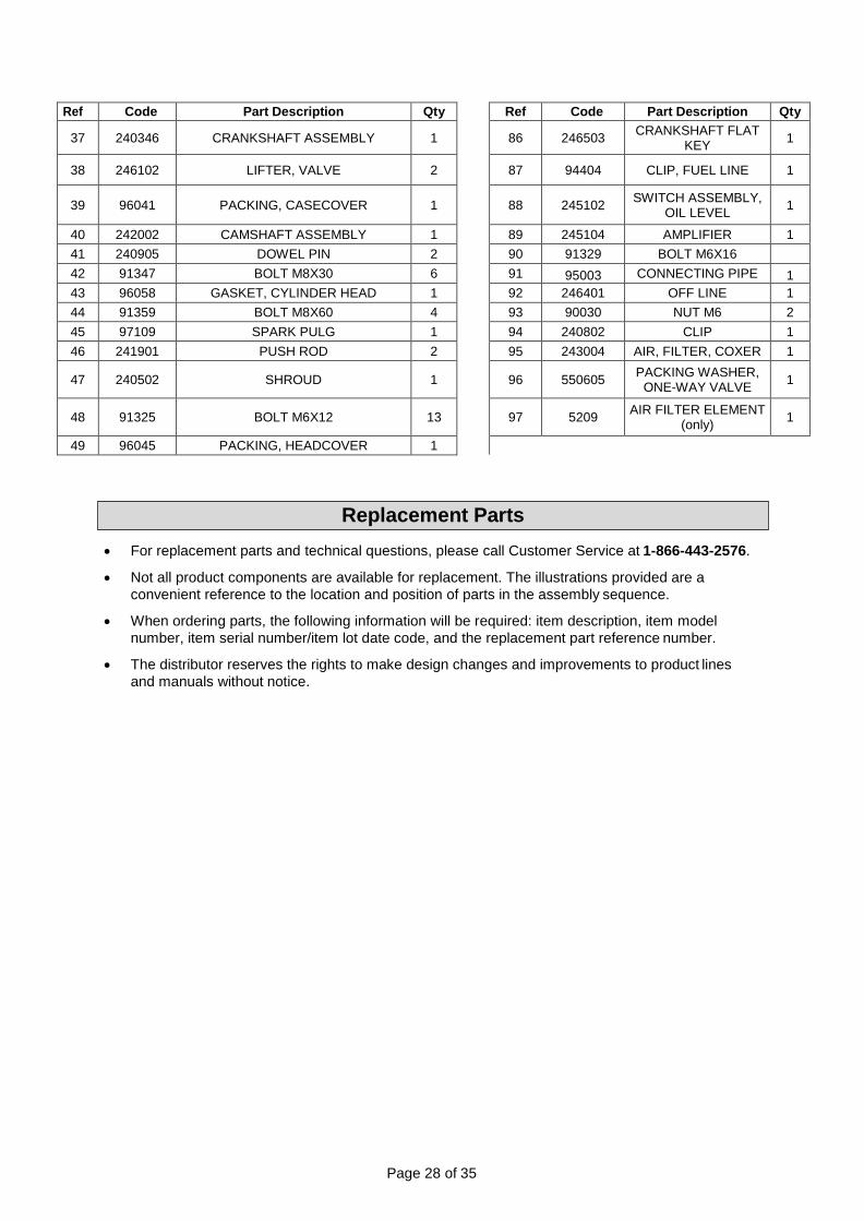
Ref Code Part Description Qty Ref Code Part Description Qty
37 240346 CRANKSHAFT ASSEMBLY 1 86 246503 CRANKSHAFT FLAT
KEY 1
38 246102 LIFTER, VALVE 2 87 94404 CLIP, FUEL LINE 1
39 96041 PACKING, CASECOVER 1 88 245102 SWITCH ASSEMBLY,
OIL LEVEL 1
40 242002 CAMSHAFT ASSEMBLY 1 89 245104 AMPLIFIER 1
41 240905 DOWEL PIN 2 90 91329 BOLT M6X16
42 91347 BOLT M8X30 6 91 95003 CONNECTING PIPE 1
43 96058 GASKET, CYLINDER HEAD 1 92 246401 OFF LINE 1
44 91359 BOLT M8X60 4 93 90030 NUT M6 2
45 97109 SPARK PULG 1 94 240802 CLIP 1
46 241901 PUSH ROD 2 95 243004 AIR, FILTER, COXER 1
47 240502 SHROUD 1 96 550605 PACKING WASHER,
ONE-WAY VALVE 1
48 91325 BOLT M6X12 13 97 5209 AIR FILTER ELEMENT
(only) 1
49 96045 PACKING, HEADCOVER 1
• For replacement parts and technical questions, please call Customer Service at 1-866-443-2576.
• Not all product components are available for replacement. The illustrations provided are a
convenient reference to the location and position of parts in the assembly sequence.
• When ordering parts, the following information will be required: item description, item model
number, item serial number/item lot date code, and the replacement part reference number.
• The distributor reserves the rights to make design changes and improvements to product lines
and manuals without notice.
Replacement Parts

E795771A_2018
U.S EPA AND CALIFORNIA EMISSION CONTROL
WARRANTY STATEMENT
YOUR WARRANTY RIGHTS AND OBLIGATIONS The California Air Resources Board, the United States Environmental Protection Agency (US EPA) and Northern Tool & Equipment Company, Inc. are pleased to explain the emission control system warranty on your 2018 - 2019 small off-road engine.
In the United States and California new small off-road engines must be designed built and equipped to meet the State’s stringent anti-smog standards. Northern Tool & Equipment Company, Inc. must warrant the emission control system on your small off-road engine for the periods of time listed below provided there has been no abuse, neglect or improper maintenance of your small off-road engine.
Your emission control system may include parts such as the carburetor, fuel tanks, cans and lines, fuel injection system, the ignition system and catalytic converter. Also included may be hoses, belts, connectors and other emission related assemblies.
Where a warrantable condition exists, Northern Tool & Equipment Company, Inc. will repair your small off-road engine at no cost to you including diagnosis, parts and labor.
MANUFACTURER’S WARRANTY COVERAGE The emissions control system is warranted for two years. If any emissions-related part on your engine is defective, the part will be repaired or replaced by Northern Tool & Equipment Company, Inc.
OWNER’S WARRANTY RESPONSIBILITIES As the small off-road engine owner, you are responsible for the performance of the required maintenance listed in your owner’s manual. Northern Tool & Equipment Company, Inc. recommends that you retain all receipts covering maintenance on your small off-road engine, but Northern Tool & Equipment Company, Inc. cannot deny warranty solely for the lack of receipts or for your failure to ensure the performance of all scheduled maintenance.
As the small off-road engine owner, you should however be aware that Northern Tool & Equipment Company, Inc. may deny you warranty coverage if your small off-road engine or a part has failed due to abuse, neglect, improper maintenance or unapproved modifications.
You are responsible for presenting your small off-road engine to a Northern Tool & Equipment Company, Inc. distribution center or service center as soon as a problem exists. The warranty repairs should be completed in a reasonable amount of time, not to exceed 30 days.
If you have any questions regarding your warranty rights and responsibilities, contact Northern Tool & Equipment Company, Inc.:
TEL: 1-866-443-2576 or visit: www.northerntool.com
This telephone number is only for the engines which the company name “Northern Tool & Equipment Company, Inc.” on the emission label.

E795771A_2018
DEFECTS WARRANTY COVERAGE Adopted by the Air Resources Board, Northern Tool & Equipment Company, Inc. warrants to the ultimate purchaser and each subsequent purchaser that the small off-road engine (1) has been designed, built and equipped so as to conform with all applicable regulations; and (2) is free from defects in materials and workmanship that cause the failure of a warranted part to conform with those regulations as may be applicable to the terms and conditions stated below:
(a) The warranty period begins on the date the engine is delivered to an ultimate purchaser or first placed into service. The warranty period is two years.
(b) Subject to certain conditions and exclusions as stated below, the warranty on emissions related parts is as follows:
(1) Any warranted part that is not scheduled for replacement as required maintenance in your Owner’s Manual is warranted for the warranty period stated above. If the part fails during the period of warranty coverage, the part will be repaired or replaced by Northern Tool & Equipment Company, Inc. according to Subsection (4) below. Any such part repaired or replaced under the warranty will be warranted for the remainder of the period.
(2) Any warranted part that is scheduled only for regular inspection in your Owner’s Manual is warranted for the warranty period stated above. Any such part repaired or replaced under warranty will be warranted for the remaining warranty period.
(3) Any warranted part that is scheduled for replacement as required maintenance in your Owner’s Manual is warranted for the period of time before the first scheduled replacement date for that part. If the part fails before the first scheduled replacement, the part will be repaired or replaced by Northern Tool & Equipment Company, Inc. according to Subsection (4) below. Any such part repaired or replaced under warranty will be warranted for the remainder of the period prior to the first scheduled replacement point for the part.
(4) Repair or replacement of any warranted part under the warranty provisions herein must be performed at a warranty station at no charge to the owner.
(5) Notwithstanding the provisions herein, warranty services or repairs will be provided at all of our distribution centers that are franchised to service the subject engines.
(6) The engine owner must not be charged for diagnostic labor that leads to the determination that a warranted part is in fact defective, provided that such diagnostic work is performed at a warranty station.
(7) Northern Tool & Equipment Company, Inc. is liable for damages to other engine components proximately caused by a failure under warranty of any warranted part.
(8) Throughout the engine warranty period stated above, Northern Tool & Equipment Company, Inc. will maintain a supply of warranted parts sufficient to meet the expected demand for such parts.
E795771A_2018
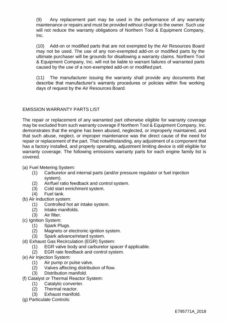
(9) Any replacement part may be used in the performance of any warranty maintenance or repairs and must be provided without charge to the owner. Such use will not reduce the warranty obligations of Northern Tool & Equipment Company, Inc.
(10) Add-on or modified parts that are not exempted by the Air Resources Board may not be used. The use of any non-exempted add-on or modified parts by the ultimate purchaser will be grounds for disallowing a warranty claims. Northern Tool & Equipment Company, Inc. will not be liable to warrant failures of warranted parts caused by the use of a non-exempted add-on or modified part.
(11) The manufacturer issuing the warranty shall provide any documents that describe that manufacturer’s warranty procedures or policies within five working days of request by the Air Resources Board.
EMISSION WARRANTY PARTS LIST
The repair or replacement of any warranted part otherwise eligible for warranty coverage may be excluded from such warranty coverage if Northern Tool & Equipment Company, Inc. demonstrates that the engine has been abused, neglected, or improperly maintained, and that such abuse, neglect, or improper maintenance was the direct cause of the need for repair or replacement of the part. That notwithstanding, any adjustment of a component that has a factory installed, and properly operating, adjustment limiting device is still eligible for warranty coverage. The following emissions warranty parts for each engine family list is covered.
(a) Fuel Metering System:
(1) Carburetor and internal parts (and/or pressure regulator or fuel injection system).
(2) Air/fuel ratio feedback and control system. (3) Cold start enrichment system. (4) Fuel tank.
(b) Air induction system: (1) Controlled hot air intake system. (2) Intake manifolds. (3) Air filter.
(c) Ignition System: (1) Spark Plugs. (2) Magneto or electronic ignition system. (3) Spark advance/retard system.
(d) Exhaust Gas Recirculation (EGR) System: (1) EGR valve body and carburetor spacer if applicable. (2) EGR rate feedback and control system.
(e) Air Injection System: (1) Air pump or pulse valve. (2) Valves affecting distribution of flow. (3) Distribution manifold.
(f) Catalyst or Thermal Reactor System: (1) Catalytic converter. (2) Thermal reactor. (3) Exhaust manifold.
(g) Particulate Controls:

E795771A_2018
(1) Traps, filters, precipitators, and any other device used to capture particulate emissions.
(h) Miscellaneous Items Used in Above Systems: (1) Electronic controls (2) Vacuum, temperature, and time sensitive valves and switches. (3) Hoses, belts, connectors, and assemblies.
Northern Tool & Equipment Company, Inc. will furnish with each new engine written instructions for the maintenance and use of the engine by the owner.

Distributed by:
Northern Tool & Equipment Company, Inc.
Burnsville, Minnesota 55306
www.northerntool.com
Made in China