21.1 design of canals - nptel
TRANSCRIPT
Hydraulics Prof. B.S. Thandaveswara
Indian Institute of Technology Madras
21.1 Design of Canals Many procedures have been developed over the years for the hydraulic design of open
channel sections. The complexity of these procedures vary according to flow conditions
as well as the level of assumption implied while developing the given equation. The
Chezy equation is one of the procedures that was developed by a French engineer in
1768 (Henderson, 1966). The development of this equation was based on the
dimensional analysis of the friction equation under the assumption that the condition of
flow is uniform. A more practical procedure was presented in 1889 by the Irish engineer
Robert Manning (Chow, 1959). The Manning equation has proved to be very reliable in
practice.
The Manning equation invokes the determination of flow velocity based on the slope of
channel bed, surface roughness of the channel, cross-sectional area of flow, and wetted
perimeter of flow. Using this equation, the solution procedures are direct for
determination of flow velocity, slope of channel bed, and surface roughness. However,
the solution for any unknown related to the cross-sectional area of flow and wetted
perimeter involves the implementation of an implicit recursive solution procedure which
cannot be achieved analytically. Many implicit solution procedures such as the Newton-
Raphson, Regula-Falsi (false position), secant, and the Van Wijngaarden-Dekker-Brent
Methods (Press et al., 1992).
One of the important topics in the area of Free surface flows is the design of channels
capable of transporting water between two locations in a safe, cost - effective manner.
Even though economics, safety, and aesthetics must always be considered, in this unit
thrust is given only to the hydraulic aspects of channel design. For that discussion is
confined to the design of channels for uniform flow. The two types of channels
considered are
(1) lined or nonerodible; (2) unlined, earthen, or erodible. There are some basic issues common to both the types and are presented in the
following paragraphs.
Hydraulics Prof. B.S. Thandaveswara
Indian Institute of Technology Madras
1. Shape of the cross section of the canal.
2. Side slope of the canal.
3. Longitudinal bed slope.
4. Permissible velocities - Maximum and Minimum.
5. Roughness coefficient.
6. Free board.
1. Shape of cross section
From the Manning and Chezy equation, it is obvious that the conveyance of a channel
increases as the hydraulic radius increases or as the wetted perimeter decreases. Thus,
there is among all channel cross sections of a specified geometric shape and ares an
optimum set of dimensions for that shape from the viewpoint of hydraulics. Among all
possible channel cross sections, the hydraulically efficient section is a semicircle since,
for a given area, it has the minimum wetted perimeter. The proportions of the
hydraulically efficient section of a specified geometric shape can be easily derived. The
geometric elements of these sections are summarized in Table. It should be noted that ,
the hydraulically efficient section is not necessarily the most economic section.
In practice the following factors are to be kept in mind:
a. The hydraulically efficient section minimizes the area required to convey a specified
discharge. however, the area which required to be excavated to achieve the flow area
required by the hydraulically efficient section may be much larger if one considers the
removal of the over burden.
b. It may not be possible to construct a hydraulically efficient stable section in the
available natural condition. If the channel is to be lined, the cost of the lining may be
comparable with the cost of excavation.
c. The cost of excavation depends on the amount of material that is to removed, in
addition to. Further Topography of the land access to the site also influence the cost of
disposal of the material removed.
d. The slope of the channel bed must be considered also as a variable since it is not
necessarily completely defined by topographic consideration. For example, a reduced
Hydraulics Prof. B.S. Thandaveswara
Indian Institute of Technology Madras
channel slope may require a larger flow area to convey the flow, on the other hand the
cost of excavation of the overburden may be reduced.
2. Side slopes
The side slopes of a channel depend primarily on the engineering properties of the
material through which the channel is excavated. From a practical viewpoint, the
side slopes should be suitable for prelimianary purposes. However, in deep cuts, side
slopes are often steeper above the water surface than they would be in an irrigation
canal excavated in the same material.In many cases, side slopes are determined by the
economics of construction. In this regard following observations are made:
a. In many unlined earthen canals, side slopes are usually 1.5 : 1; However,
side slopes as steep as 1:1 have been used when the channel runs through cohesive
materials.
b. In lined canals, the side slopes are generally steeper than in an unlined canal. If
concrete is the lining material, side slopes greater than 1 : 1 usually require the use of
forms, and with side slopes greater than 0 .75 : 1 the linings must be designed to
withstand earth pressures. Some types of lining require side slopes as flat as those
used for unlined channels.
c. Side slopes through cuts in rock can be vertical if this is desirable.
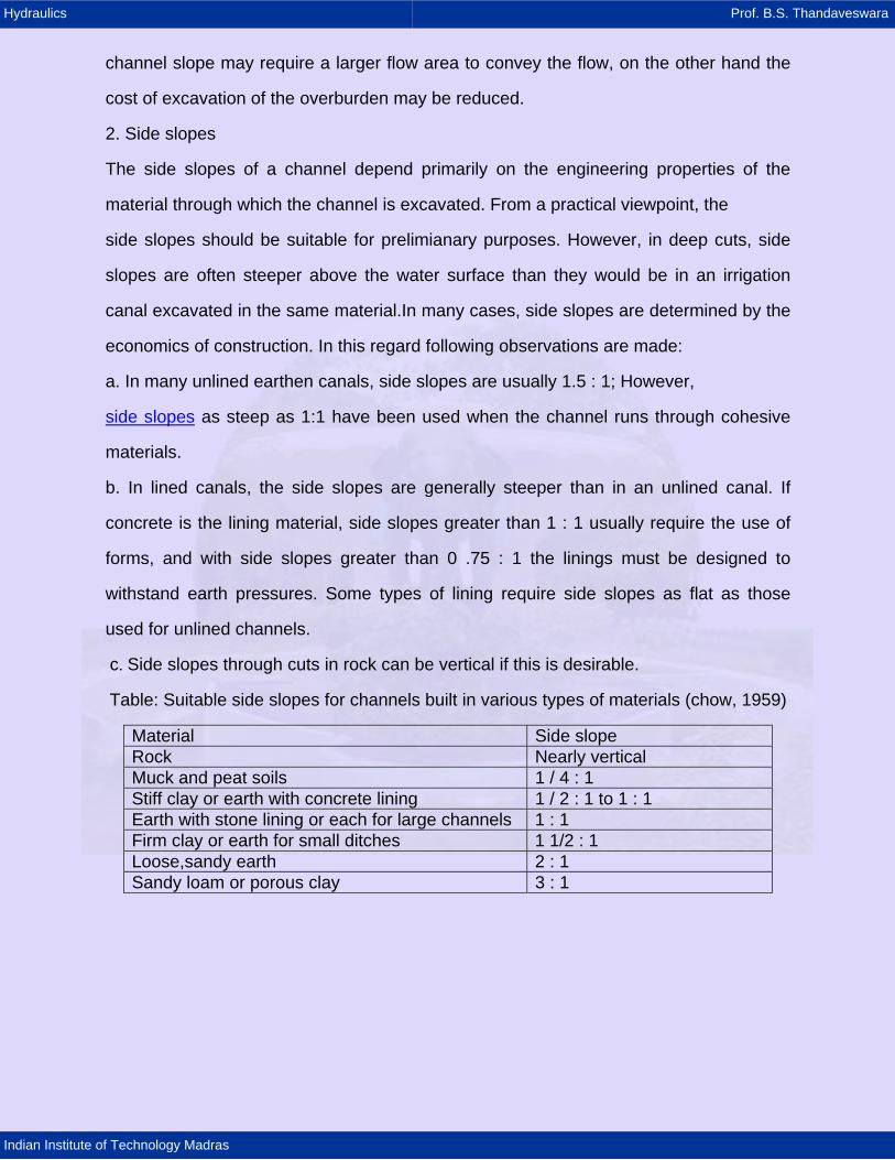
Table: Suitable side slopes for channels built in various types of materials (chow, 1959)
Material Side slope Rock Nearly vertical Muck and peat soils 1 / 4 : 1 Stiff clay or earth with concrete lining 1 / 2 : 1 to 1 : 1 Earth with stone lining or each for large channels 1 : 1 Firm clay or earth for small ditches 1 1/2 : 1 Loose,sandy earth 2 : 1 Sandy loam or porous clay 3 : 1
Hydraulics Prof. B.S. Thandaveswara
Indian Institute of Technology Madras
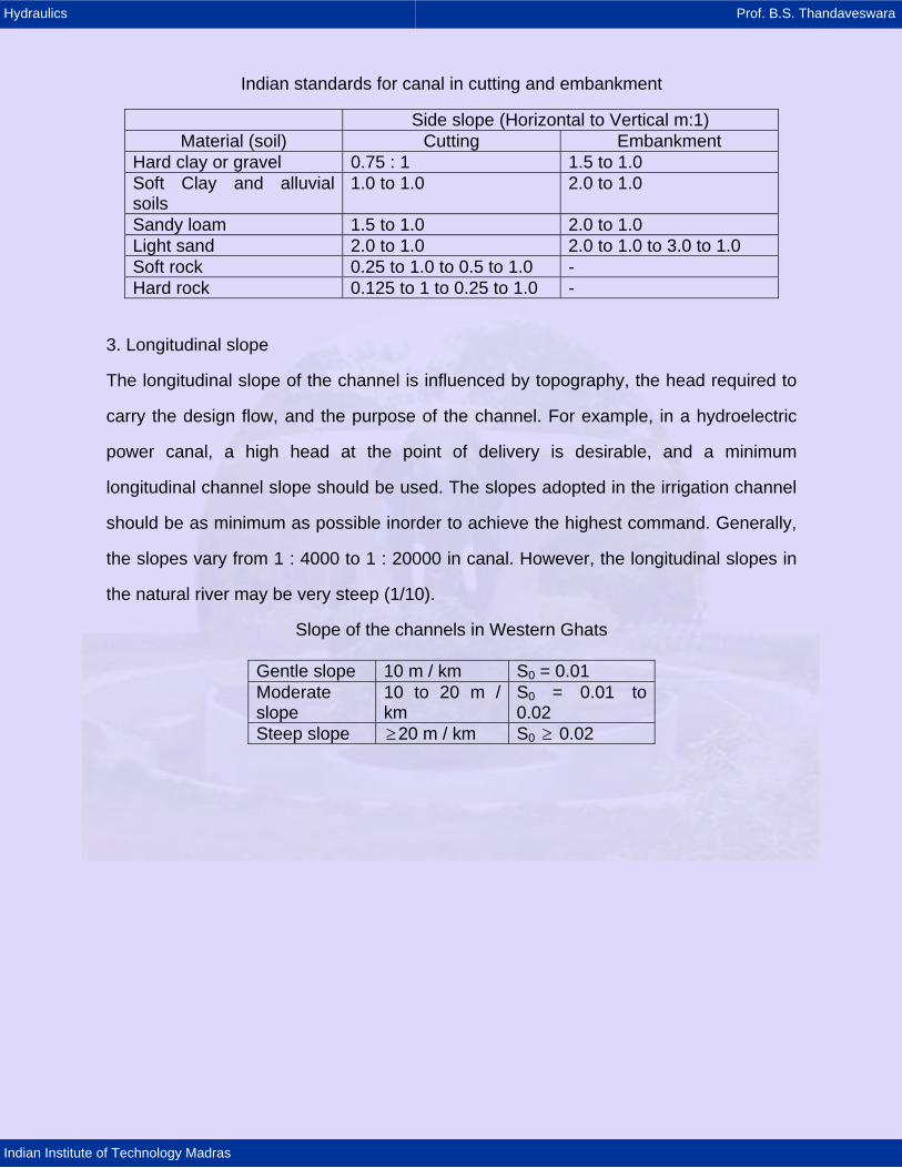
Indian standards for canal in cutting and embankment
Side slope (Horizontal to Vertical m:1) Material (soil) Cutting Embankment
Hard clay or gravel 0.75 : 1 1.5 to 1.0 Soft Clay and alluvial soils
1.0 to 1.0 2.0 to 1.0
Sandy loam 1.5 to 1.0 2.0 to 1.0 Light sand 2.0 to 1.0 2.0 to 1.0 to 3.0 to 1.0 Soft rock 0.25 to 1.0 to 0.5 to 1.0 - Hard rock 0.125 to 1 to 0.25 to 1.0 -
3. Longitudinal slope
The longitudinal slope of the channel is influenced by topography, the head required to
carry the design flow, and the purpose of the channel. For example, in a hydroelectric
power canal, a high head at the point of delivery is desirable, and a minimum
longitudinal channel slope should be used. The slopes adopted in the irrigation channel
should be as minimum as possible inorder to achieve the highest command. Generally,
the slopes vary from 1 : 4000 to 1 : 20000 in canal. However, the longitudinal slopes in
the natural river may be very steep (1/10).
Slope of the channels in Western Ghats
Gentle slope 10 m / km S0 = 0.01 Moderate slope
10 to 20 m / km
S0 = 0.01 to 0.02
Steep slope ≥20 m / km S0 0.02 ≥
Hydraulics Prof. B.S. Thandaveswara
Indian Institute of Technology Madras
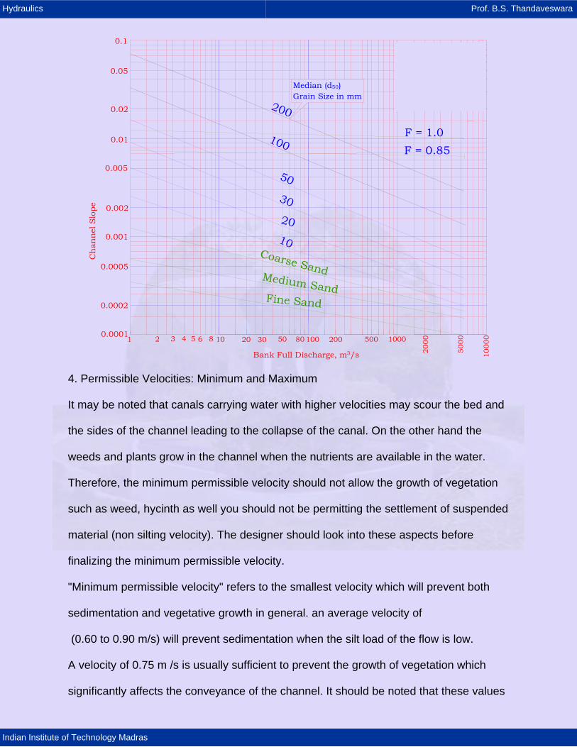
0.1
0.05
0.02
0.01
0.005
0.002
0.001
0.0005
0.0002
0.0001
Median (d50) Grain Size in mm
F = 0.85F = 1.0
Bank Full Discharge, m3/s
4. Permissible Velocities: Minimum and Maximum It may be noted that canals carrying water with higher velocities may scour the bed and the sides of the channel leading to the collapse of the canal. On the other hand the weeds and plants grow in the channel when the nutrients are available in the water. Therefore, the minimum permissible velocity should not allow the growth of vegetation such as weed, hycinth as well you should not be permitting the settlement of suspended material (non silting velocity). The designer should look into these aspects before finalizing the minimum permissible velocity. "Minimum permissible velocity" refers to the smallest velocity which will prevent both sedimentation and vegetative growth in general. an average velocity of (0.60 to 0.90 m/s) will prevent sedimentation when the silt load of the flow is low. A velocity of 0.75 m /s is usually sufficient to prevent the growth of vegetation which significantly affects the conveyance of the channel. It should be noted that these values
Hydraulics Prof. B.S. Thandaveswara
Indian Institute of Technology Madras
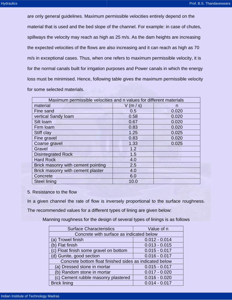
are only general guidelines. Maximum permissible velocities entirely depend on the material that is used and the bed slope of the channel. For example: in case of chutes, spillways the velocity may reach as high as 25 m/s. As the dam heights are increasing the expected velocities of the flows are also increasing and it can reach as high as 70 m/s in exceptional cases. Thus, when one refers to maximum permissible velocity, it is for the normal canals built for irrigation purposes and Power canals in which the energy loss must be minimised. Hence, following table gives the maximum permissible velocity for some selected materials.
Maximum permissible velocities and n values for different materials material V (m / s) n Fine sand 0.5 0.020 vertical Sandy loam 0.58 0.020 Silt loam 0.67 0.020 Firm loam 0.83 0.020 Stiff clay 1.25 0.025 Fine gravel 0.83 0.020 Coarse gravel 1.33 0.025 Gravel 1.2 Disintegrated Rock 1.5 Hard Rock 4.0 Brick masonry with cement pointing 2.5 Brick masonry with cement plaster 4.0 Concrete 6.0 Steel lining 10.0
5. Resistance to the flow
In a given channel the rate of flow is inversely proportional to the surface roughness.
The recommended values for a different types of lining are given below:
Manning roughness for the design of several types of linings is as follows
Surface Characteristics Value of n Concrete with surface as indicated below
(a) Trowel finish 0.012 - 0.014 (b) Flat finish 0.013 - 0.015 (c) Float finish some gravel on bottom 0.015 - 0.017 (d) Gunite, good section 0.016 - 0.017
Concrete bottom float finished sides as indicated below (a) Dressed stone in mortar 0.015 - 0.017 (b) Random stone in mortar 0.017 - 0.020 (c) Cement rubble masonry plastered 0.016 - 0.020 Brick lining 0.014 - 0.017

Hydraulics Prof. B.S. Thandaveswara
Indian Institute of Technology Madras
Asphalt lining (a) Smooth 0.013 (b) Rough 0.016
Concrete lined excavated rock with (a) Good section 0.017 - 0.020 (b) Irregular section 0.022 - 0.027
These values should, however, be adopted only where the channel has flushing
velocity. In case the channel has non-flushing velocity the value of n may increase due
to deposition of silt in coarse of time and should in such cases be taken as that for
earthen channel. The actual value of n in Manning formula evaluated on the basis of
observations taken on Yamuna Power Channel in November 1971 ranged between
0.0175 and 0.0229 at km 0.60 and between 0.0164 and 0.0175 at km 2.05. The higher
value of n evaluated at km 0.60 could be attributed to the deposition of silt in head
reaches of the channel.
Table: Manning Roughness Coefficients
n-value different depth ranges Depth ranges
Lining Category
Lining Type
0 – 15 cm 15 – 60 cm > 60 cm Concrete 0.015 0.013 0.013 Grouted Riprap 0.040 0.030 0.028 Stone Masonry 0.042 0.032 0.030 Soil Cement 0.025 0.022 0.020
Rigid Asphalt 0.018 0.016 0.016 Bare Soil 0.023 0.020 0.020
Unlined Rock Cut 0.045 0.035 0.025
Woven Paper Net 0.016 0.015 0.015 Jute Net 0.028 0.022 0.019 Fiberglass Roving 0.028 0.021 0.019 Straw with Net 0.065 0.033 0.025 Cured Wood Mat 0.066 0.035 0.028
Temporary Synthetic Mat 0.036 0.025 0.021 2.5-cm (d50) 0.044 0.033 0.030
Gravel Riprap
5 -cm (d50) 0.066 0.041 0.034
15-cm (d50) 0.104 0.069 0.035 Rock
Riprap 30-cm (d50) - 0.078 0.040
Hydraulics Prof. B.S. Thandaveswara
Indian Institute of Technology Madras
6. Freeboard
The term freeboard refers to the vertical distance between either the top of the channel
or the top of the channel is carrying the design flow at normal depth. The purpose of
freeboard is to prevent the overtopping of either the lining or the top of the channel
fluctuations in the water surface caused by
(1) wind - driven waves,
(2) tidal action,
(3) hydraulic jumps,
(4) superelevation of the water surface as the flow goes round curves at high velocities,
(5) the interception of storm runoff by the channel,
(6) the occurrence of greater than design depths of flow caused by canal sedimentation
or an increased coefficient of friction, or
(7) temporary mis-operation of the canal system.
There is no universally accepted role for the determination of free board since, waves,
unsteady flow condition, curves etc., influence the free board. Free boards varying from
less than 5% to 30% of the depth are commonly used in design. In semi-circular
channels, when the velocities are less than 0.8 times the critical velocity then 6% of the
diameter as free board have been proved to be adequate.
The freeboard associated with channel linings and the absolute top of the canal above
the water surface can be estimated from the empirical curves. In general, those curves
apply to a channel lined with either a hard surface, a membrane, or compacted earth
with a low coefficient of permeability. For unlined channels, freeboard generally ranges
from 0.3m for small laterals with shallow depths of flow to 1.2m for channels carrying 85
m3 /s at relatively large depths of flow. A prelimimary estimate of freeboard for an
unlined channel can be obtained from USBR formula.
B
B1/ 2
3
F Cyin which F
C is a coefficient. However, it may be noted that C has dim ensions of L .
C var ies from 1.5 at Q 0.57 m / s to
is the freeboard in feet, y is the design depth of flow in feet,
=
=3
2.5 for canal
capacity equal to and more than 85 m / s.
Hydraulics Prof. B.S. Thandaveswara
Indian Institute of Technology Madras
The free board recommended by USBR for channels are given below
Q m3/s Free board FB in m < 0.75 0.45
0.75 - 1.5 0.60 1.5 - 85.0 0.75
> 85 0.90
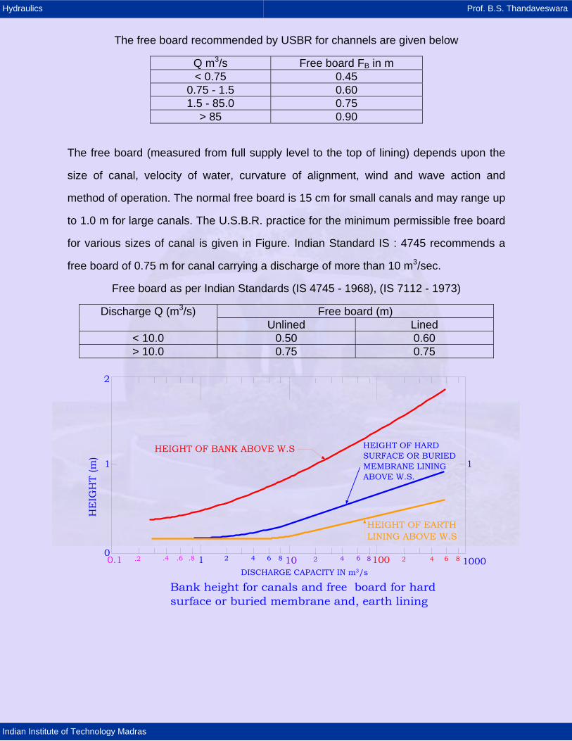
The free board (measured from full supply level to the top of lining) depends upon the
size of canal, velocity of water, curvature of alignment, wind and wave action and
method of operation. The normal free board is 15 cm for small canals and may range up
to 1.0 m for large canals. The U.S.B.R. practice for the minimum permissible free board
for various sizes of canal is given in Figure. Indian Standard IS : 4745 recommends a
free board of 0.75 m for canal carrying a discharge of more than 10 m3/sec.
Free board as per Indian Standards (IS 4745 - 1968), (IS 7112 - 1973)
Free board (m) Discharge Q (m3/s) Unlined Lined
< 10.0 0.50 0.60 > 10.0 0.75 0.75
HEIGHT OF BANK ABOVE W.S HEIGHT OF HARDSURFACE OR BURIEDMEMBRANE LININGABOVE W.S.
HEIGHT OF EARTHLINING ABOVE W.S
DISCHARGE CAPACITY IN m3/s
Bank height for canals and free board for hard surface or buried membrane and, earth lining
1
2
0.1 .2 .4 .6 .8 1 2 4 6 8 10 2 4 6 8 10000
1
100 2 4 6 8
Hydraulics Prof. B.S. Thandaveswara
Indian Institute of Technology Madras
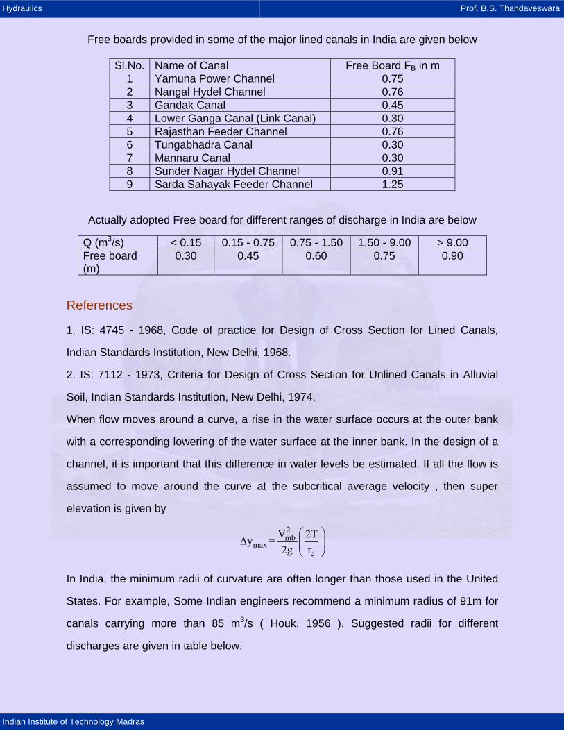
Free boards provided in some of the major lined canals in India are given below
Sl.No. Name of Canal Free Board FB in m 1 Yamuna Power Channel 0.75 2 Nangal Hydel Channel 0.76 3 Gandak Canal 0.45 4 Lower Ganga Canal (Link Canal) 0.30 5 Rajasthan Feeder Channel 0.76 6 Tungabhadra Canal 0.30 7 Mannaru Canal 0.30 8 Sunder Nagar Hydel Channel 0.91 9 Sarda Sahayak Feeder Channel 1.25
Actually adopted Free board for different ranges of discharge in India are below
Q (m3/s) < 0.15 0.15 - 0.75 0.75 - 1.50 1.50 - 9.00 > 9.00 Free board (m)
0.30 0.45 0.60 0.75 0.90
References
1. IS: 4745 - 1968, Code of practice for Design of Cross Section for Lined Canals,
Indian Standards Institution, New Delhi, 1968.
2. IS: 7112 - 1973, Criteria for Design of Cross Section for Unlined Canals in Alluvial
Soil, Indian Standards Institution, New Delhi, 1974.
When flow moves around a curve, a rise in the water surface occurs at the outer bank
with a corresponding lowering of the water surface at the inner bank. In the design of a
channel, it is important that this difference in water levels be estimated. If all the flow is
assumed to move around the curve at the subcritical average velocity , then super
elevation is given by
2mb
maxc
V 2T∆y =2g r
⎛ ⎞⎜ ⎟⎝ ⎠
In India, the minimum radii of curvature are often longer than those used in the United
States. For example, Some Indian engineers recommend a minimum radius of 91m for
canals carrying more than 85 m3/s ( Houk, 1956 ). Suggested radii for different
discharges are given in table below.
Hydraulics Prof. B.S. Thandaveswara
Indian Institute of Technology Madras
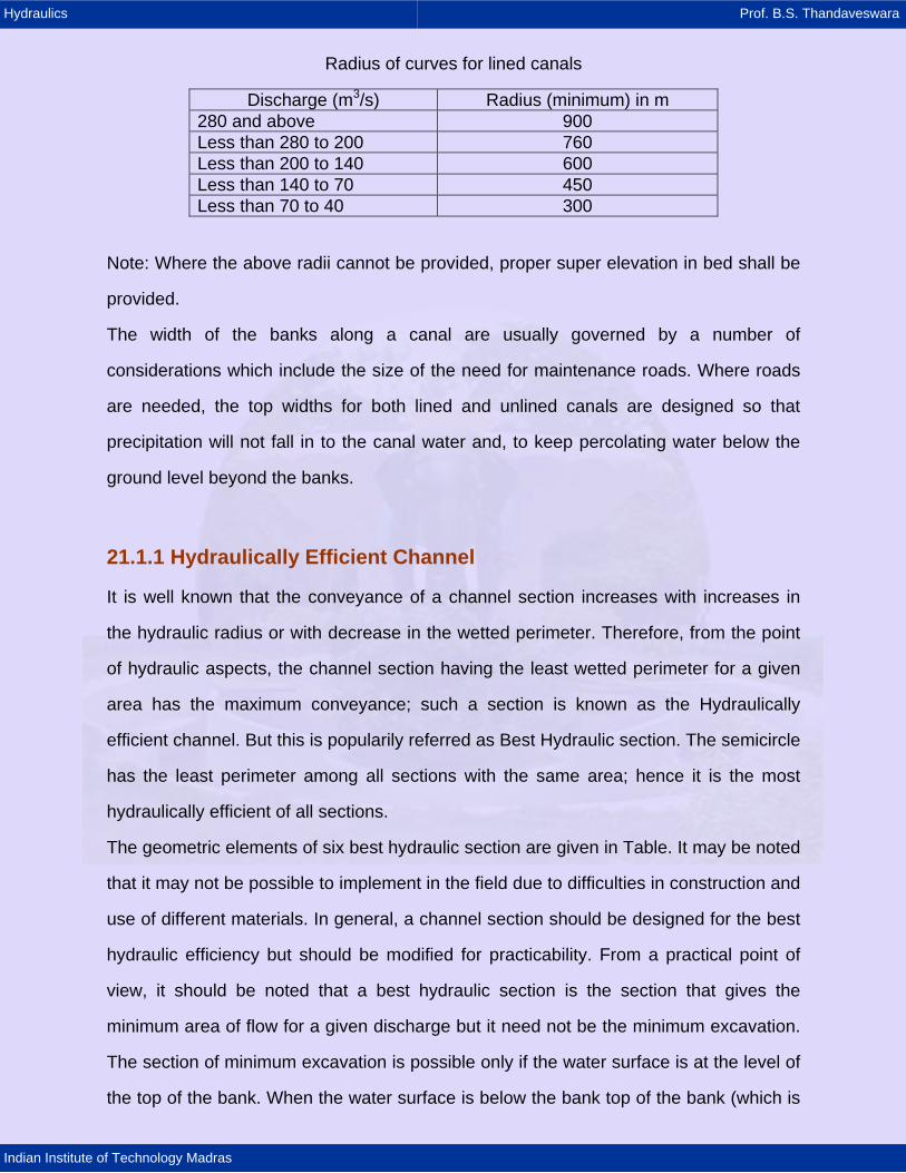
Radius of curves for lined canals
Discharge (m3/s) Radius (minimum) in m 280 and above 900 Less than 280 to 200 760 Less than 200 to 140 600 Less than 140 to 70 450 Less than 70 to 40 300
Note: Where the above radii cannot be provided, proper super elevation in bed shall be
provided.
The width of the banks along a canal are usually governed by a number of
considerations which include the size of the need for maintenance roads. Where roads
are needed, the top widths for both lined and unlined canals are designed so that
precipitation will not fall in to the canal water and, to keep percolating water below the
ground level beyond the banks.
21.1.1 Hydraulically Efficient Channel
It is well known that the conveyance of a channel section increases with increases in
the hydraulic radius or with decrease in the wetted perimeter. Therefore, from the point
of hydraulic aspects, the channel section having the least wetted perimeter for a given
area has the maximum conveyance; such a section is known as the Hydraulically
efficient channel. But this is popularily referred as Best Hydraulic section. The semicircle
has the least perimeter among all sections with the same area; hence it is the most
hydraulically efficient of all sections.
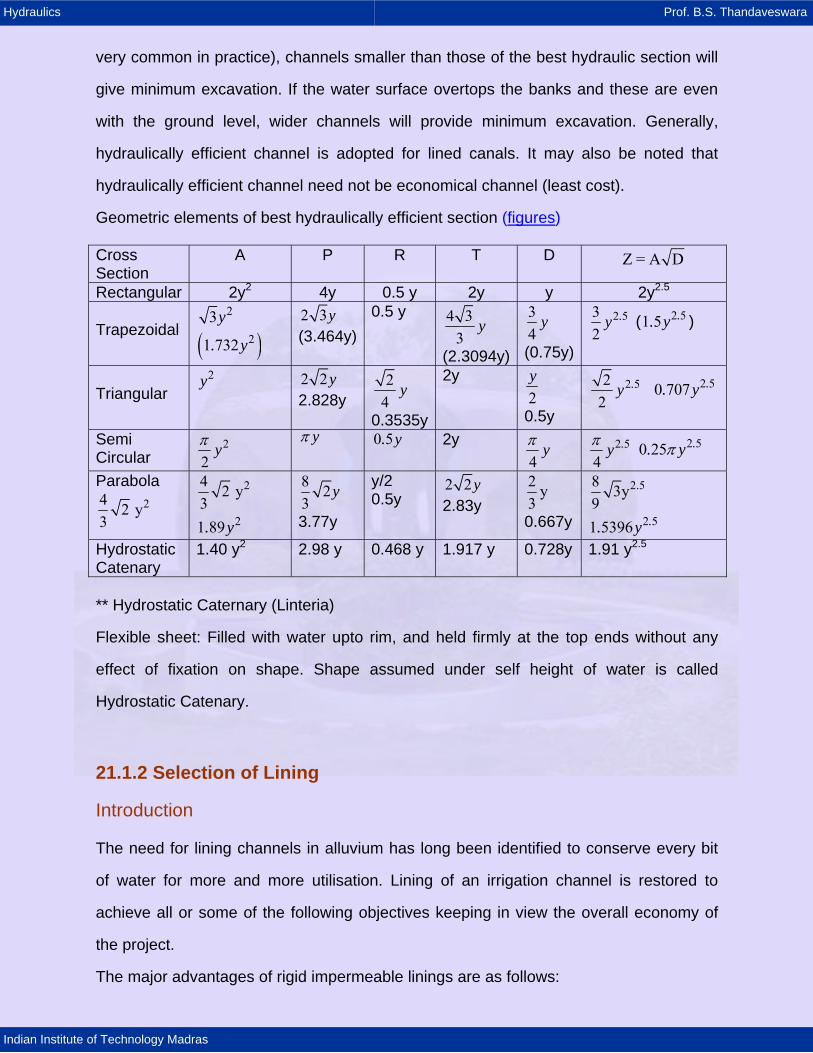
The geometric elements of six best hydraulic section are given in Table. It may be noted
that it may not be possible to implement in the field due to difficulties in construction and
use of different materials. In general, a channel section should be designed for the best
hydraulic efficiency but should be modified for practicability. From a practical point of
view, it should be noted that a best hydraulic section is the section that gives the
minimum area of flow for a given discharge but it need not be the minimum excavation.
The section of minimum excavation is possible only if the water surface is at the level of
the top of the bank. When the water surface is below the bank top of the bank (which is
Hydraulics Prof. B.S. Thandaveswara
Indian Institute of Technology Madras
very common in practice), channels smaller than those of the best hydraulic section will
give minimum excavation. If the water surface overtops the banks and these are even
with the ground level, wider channels will provide minimum excavation. Generally,
hydraulically efficient channel is adopted for lined canals. It may also be noted that
hydraulically efficient channel need not be economical channel (least cost).
Geometric elements of best hydraulically efficient section (figures) Cross Section
A P R T D Z = A D
Rectangular 2y2 4y 0.5 y 2y y 2y2.5
Trapezoidal
23y
( )21 732. y
2 3y (3.464y)
0.5 y 4 33
y
(2.3094y)
34
y
(0.75y)
2 532
.y ( ) 2 51 5 .. y
Triangular
2y 2 2y 2.828y
24
y
0.3535y
2y 2y
0.5y
2 522
.y 2 50 707 .. y
Semi Circular
2
2yπ
yπ 0 5. y 2y 4
yπ 2 5
4.yπ 2 50 25 .. yπ
Parabola 24 2 y
3
24 2 y3
21 89. y
8 23
y
3.77y
y/2 0.5y
2 2y 2.83y
2 y3
0.667y
2.58 3y9
2 51 5396 .. yHydrostatic Catenary
1.40 y2 2.98 y 0.468 y 1.917 y 0.728y 1.91 y2.5
** Hydrostatic Caternary (Linteria)
Flexible sheet: Filled with water upto rim, and held firmly at the top ends without any
effect of fixation on shape. Shape assumed under self height of water is called
Hydrostatic Catenary.
21.1.2 Selection of Lining
Introduction The need for lining channels in alluvium has long been identified to conserve every bit
of water for more and more utilisation. Lining of an irrigation channel is restored to
achieve all or some of the following objectives keeping in view the overall economy of
the project.
The major advantages of rigid impermeable linings are as follows:
Hydraulics Prof. B.S. Thandaveswara
Indian Institute of Technology Madras
(a) Reduction of seepage losses resulting in a saving of water which can be utilised for
additional irrigation.
(b) Prevention of water logging by reducing seepage to water-table. (c) Reduction in area of cross-section (and there by saving in land) due to increase in
permissible velocity by reduction in the value of rugosity and availing of steeper slope,
where available. Minimize excavation costs
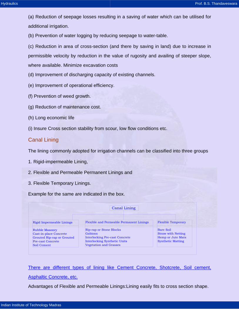
(d) Improvement of discharging capacity of existing channels. (e) Improvement of operational efficiency. (f) Prevention of weed growth. (g) Reduction of maintenance cost. (h) Long economic life (i) Insure Cross section stability from scour, low flow conditions etc. Canal Lining The lining commonly adopted for irrigation channels can be classified into three groups 1. Rigid-impermeable Lining, 2. Flexible and Permeable Permanent Linings and 3. Flexible Temporary Linings. Example for the same are indicated in the box.
Rigid Impermeable Linings
Rubble MasonryCast-in-place ConcreteGrouted Rip-rap or Grouted Pre-cast ConcreteSoil Cement
Flexible and Permeable Permanent Linings
Rip-rap or Stone BlocksGabionsInterlocking Pre-cast ConcreteInterlocking Synthetic UnitsVegetation and Grasses
Flexible Temporary
Bare SoilStraw with NettingHemp or Jute MatsSynthetic Matting
Canal Lining
There are different types of lining like Cement Concrete, Shotcrete, Soil cement,
Asphaltic Concrete, etc.
Advantages of Flexible and Permeable Linings:Lining easily fits to cross section shape.
Hydraulics Prof. B.S. Thandaveswara
Indian Institute of Technology Madras
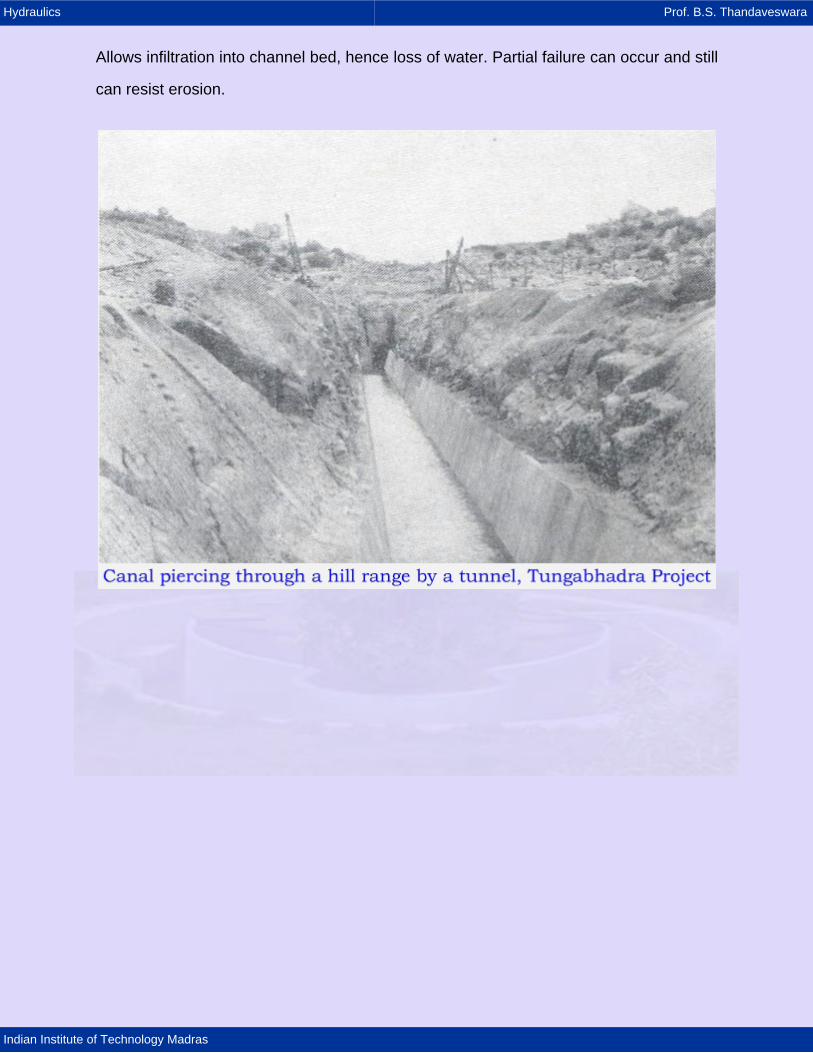
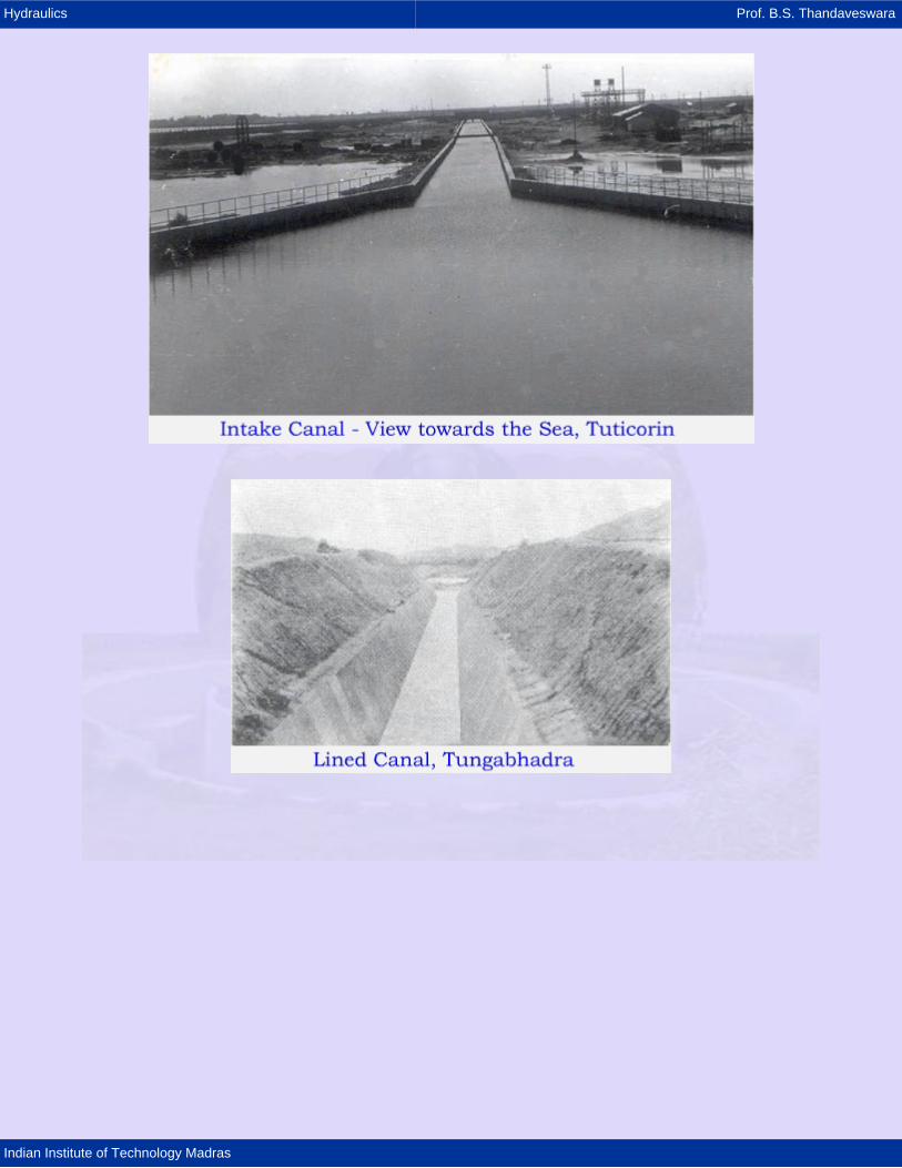
Allows infiltration into channel bed, hence loss of water. Partial failure can occur and still
can resist erosion.

Hydraulics Prof. B.S. Thandaveswara
Indian Institute of Technology Madras
Hydraulics Prof. B.S. Thandaveswara
Indian Institute of Technology Madras

Hydraulics Prof. B.S. Thandaveswara
Indian Institute of Technology Madras
21.1.3 Design of Lined Channels
Lined channels are built for five primary reasons:
1. To permit the transmission of water at high velocities through areas of deep or
difficult excavation in a cost - effective fashion.
2. To permit the transmission of water at high velocity at a reduced construction cost.
3. To decrease canal seepage, thus conserving water and reducing the waterlogging of
lands adjacent to the canal.
4. To reduce the annual cost of operation and maintenance.
5. To ensure the stability of the channel section.
Hydraulics Prof. B.S. Thandaveswara
Indian Institute of Technology Madras
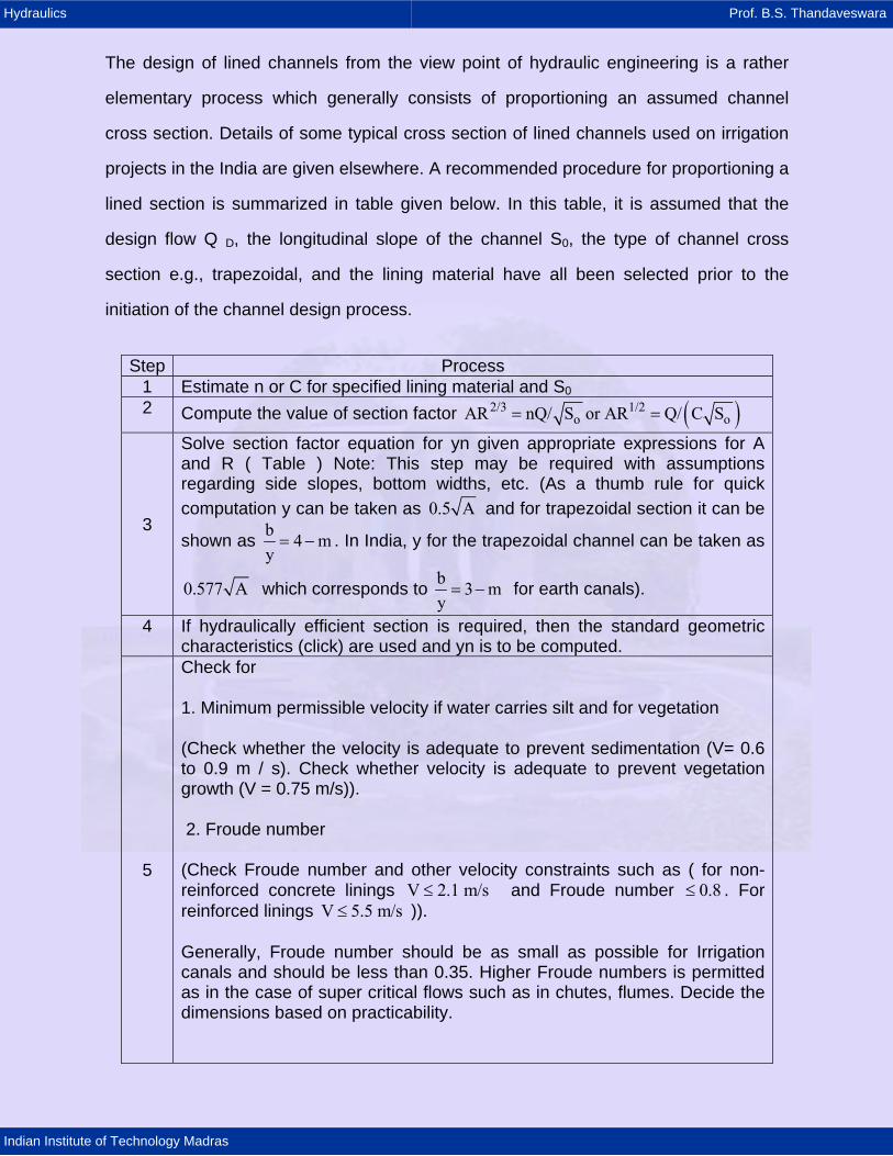
The design of lined channels from the view point of hydraulic engineering is a rather
elementary process which generally consists of proportioning an assumed channel
cross section. Details of some typical cross section of lined channels used on irrigation
projects in the India are given elsewhere. A recommended procedure for proportioning a
lined section is summarized in table given below. In this table, it is assumed that the
design flow Q D, the longitudinal slope of the channel S0, the type of channel cross
section e.g., trapezoidal, and the lining material have all been selected prior to the
initiation of the channel design process.
Step Process 1 Estimate n or C for specified lining material and S02 Compute the value of section factor ( )2/3 1/2
o oAR nQ/ S or AR Q/ C S= =
3
Solve section factor equation for yn given appropriate expressions for A and R ( Table ) Note: This step may be required with assumptions regarding side slopes, bottom widths, etc. (As a thumb rule for quick computation y can be taken as 0.5 A and for trapezoidal section it can be
shown as b 4 my= − . In India, y for the trapezoidal channel can be taken as
0.577 A which corresponds to b 3 my= − for earth canals).
4 If hydraulically efficient section is required, then the standard geometric characteristics (click) are used and yn is to be computed.
5
Check for
1. Minimum permissible velocity if water carries silt and for vegetation
(Check whether the velocity is adequate to prevent sedimentation (V= 0.6 to 0.9 m / s). Check whether velocity is adequate to prevent vegetation growth (V = 0.75 m/s)).
2. Froude number
(Check Froude number and other velocity constraints such as ( for non- reinforced concrete linings V 2.1 m/s≤ and Froude number . For reinforced linings )).
0.8≤V 5.5 m/s≤
Generally, Froude number should be as small as possible for Irrigation canals and should be less than 0.35. Higher Froude numbers is permitted as in the case of super critical flows such as in chutes, flumes. Decide the dimensions based on practicability.
Hydraulics Prof. B.S. Thandaveswara
Indian Institute of Technology Madras
6 Estimate
1. Required height of lining above water surface,
2. Required freeboard, Figure.
Balance excavations costs, costs of channel lining and assess the needs to modify "Hydraulically efficient section".
7 Summarize the results with dimensioned sketch.
Example of Rigid Lined Channel Design: Design a concrete lined channel (rough finish
n = 0.015) to carry 20 m3/s on a slope of 0.0015. Consider the hydraulically efficient
trapezoidal shape.
Solution
For hydraulically efficient trapezoidal channel
( )
2
2/3 1 20
2132 2
83
1 73 3 46 2
0 015 1Q = AR Sn
120 1 73 0 00150 015 2
7 1072 086
/
yA . y , P . y, R
n . ,
y. y ..
y .y . m
= = =
=
⎛ ⎞⎛ ⎞⎜ ⎟= ⎜ ⎟⎜ ⎟⎝ ⎠⎜ ⎟
⎝ ⎠
==
For Trapezoidal channel width is given by
( )o
2b = y, 3
b =1.15y = 2.409 m
3m = 0.5773 i.e., = 603
=
Hydraulics Prof. B.S. Thandaveswara
Indian Institute of Technology Madras
2
2
Q 20Velocity = = = 2.656 m/sA 1.73y
A 1.73yHydraulic mean depth D = = = 0.749y = 1.563 m4T y3
3
VFroude Number = 0 678gD
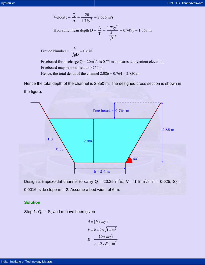
Freeboard for discharge Q = 20m /s is 0.75 m to nearest convenient elevation.Freeboard may be modified to 0.764 m.Hence, the total depth of the channel 2.086 + 0.764 = 2.850 m
.=
Hence the total depth of the channel is 2.850 m. The designed cross section is shown in
the figure.
0.764 m
2.086
0.58
1.0
60o
2.85 m
Free board =
b = 2.4 m
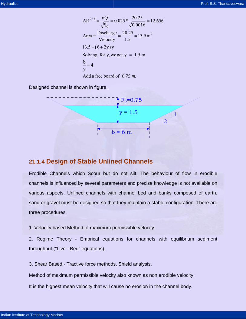
Design a trapezoidal channel to carry Q = 20.25 m3/s, V = 1.5 m3/s, n = 0.025, S0 =
0.0016, side slope m = 2. Assume a bed width of 6 m.
Solution
Step 1: Q, n, S0 and m have been given
( )
( )
2
2
2 1
2 1
A b my
P b y mb my
Rb y m
= +
= + +
+=
+ +
Hydraulics Prof. B.S. Thandaveswara
Indian Institute of Technology Madras
( )
2 /3
0
2
nQ 20.25AR 0.025* 12.656S 0.0016
Discharge 20.25Area = 13.5mVelocity 1.5
13.5 6 2y ySolving for y, weget y 1.5 mb 4yAdd a free board of
0.75 m.
= = =
= =
= +
=
=
Designed channel is shown in figure.
y = 1.5
b = 6 m
Fb=0.75
21
21.1.4 Design of Stable Unlined Channels
Erodible Channels which Scour but do not silt. The behaviour of flow in erodible
channels is influenced by several parameters and precise knowledge is not available on
various aspects. Unlined channels with channel bed and banks composed of earth,
sand or gravel must be designed so that they maintain a stable configuration. There are
three procedures.
1. Velocity based Method of maximum permissible velocity.
2. Regime Theory - Emprical equations for channels with equilibrium sediment
throughput ("Live - Bed" equations).
3. Shear Based - Tractive force methods, Shield analysis.
Method of maximum permissible velocity also known as non erodible velocity:
It is the highest mean velocity that will cause no erosion in the channel body.
Hydraulics Prof. B.S. Thandaveswara
Indian Institute of Technology Madras
When compared with the design process typically used for lined channels, the design of
stable, unlined or erodible, earthen channels is a complex process involving numerous
parameters, most of which cannot be accurately quantified. The complexity of the
erodible channel design process results from the fact that in such channels stability is
dependent not only on hydraulic parameters but also on the properties of the material
which composes the bed and sides of the channel.
A stable channel section is one in which neither objectionable scour nor deposition
occurs. There are three types of unstable sections: (USBR).
The pioneering work of Fortier and Scobey ( 1926 ) was the basis of channel design.
1. The banks and bed of the channel are scoured but no deposition occurs.
Example: When the channel conveys sediment free water (or water with only a very
small amount of sediment) but with adequate energy to erode the channel.
2. Unstable channel with deposition but no scour.
Example: When the water being conveyed carries a large sediment load at a velocity
that permits sedimentation.
3. Unstable channel with both scour and deposition occur.
Example: When the material through which the channel is excavated is susceptible to
erosion and the water being conveyed carries a significant sediment load.
These types of channels can be designed using the method of maximum permissible
velocity.
The following important points are to be noted.
1. First, the maximum permissible velocity is recommended for canals with a sinuous
alignment.
2. Second, these data are for depths of flow less than 0.91 m . For greater depths of
flow, the maximum permissible velocity should be increased by 0.15 m/s.
Hydraulics Prof. B.S. Thandaveswara
Indian Institute of Technology Madras
3. Third, the velocity of the in canals carrying abrasives, such as basalt raveling, should
be reduced by 0.15 m /s.
4. Fourth, channels diverting water from silt - laden river such as Ganga River should be
designed for mean design velocities 0.3 to 0.61 m/s greater than would be allowed for
the same perimeter material if the water were transporting no sediment.
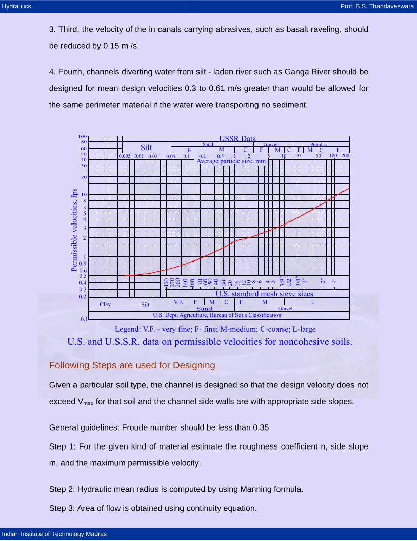
USSR DataSand Gravel PebblesSilt F M C F M C F M C L
Average particle size, mm
U.S. and U.S.S.R. data on permissible velocities for noncohesive soils.Legend: V.F. - very fine; F- fine; M-medium; C-coarse; L-large
U.S. Dept. Agriculture, Bureau of Soils Classification
Clay SiltSand Gravel
V.F. F M C F M
0.1
0.20.30.40.50.60.8
1
2
3456
810
20
30405060
80100
0.005 0.01 0.02 0.05 0.1 0.2 0.5 5 10 20 50 100 20021
L
U.S. standard mesh sieve sizes
Following Steps are used for Designing
Given a particular soil type, the channel is designed so that the design velocity does not
exceed Vmax for that soil and the channel side walls are with appropriate side slopes.
General guidelines: Froude number should be less than 0.35
Step 1: For the given kind of material estimate the roughness coefficient n, side slope
m, and the maximum permissible velocity.
Step 2: Hydraulic mean radius is computed by using Manning formula.
Step 3: Area of flow is obtained using continuity equation.
Hydraulics Prof. B.S. Thandaveswara
Indian Institute of Technology Madras
Step 4: The wetted perimeter is computed using the information obtained in steps 2
and 3.
Step 5: Solve simultaneously for b and y.
Step 6: Add a proper free board. Modify the section for practicality.
Example
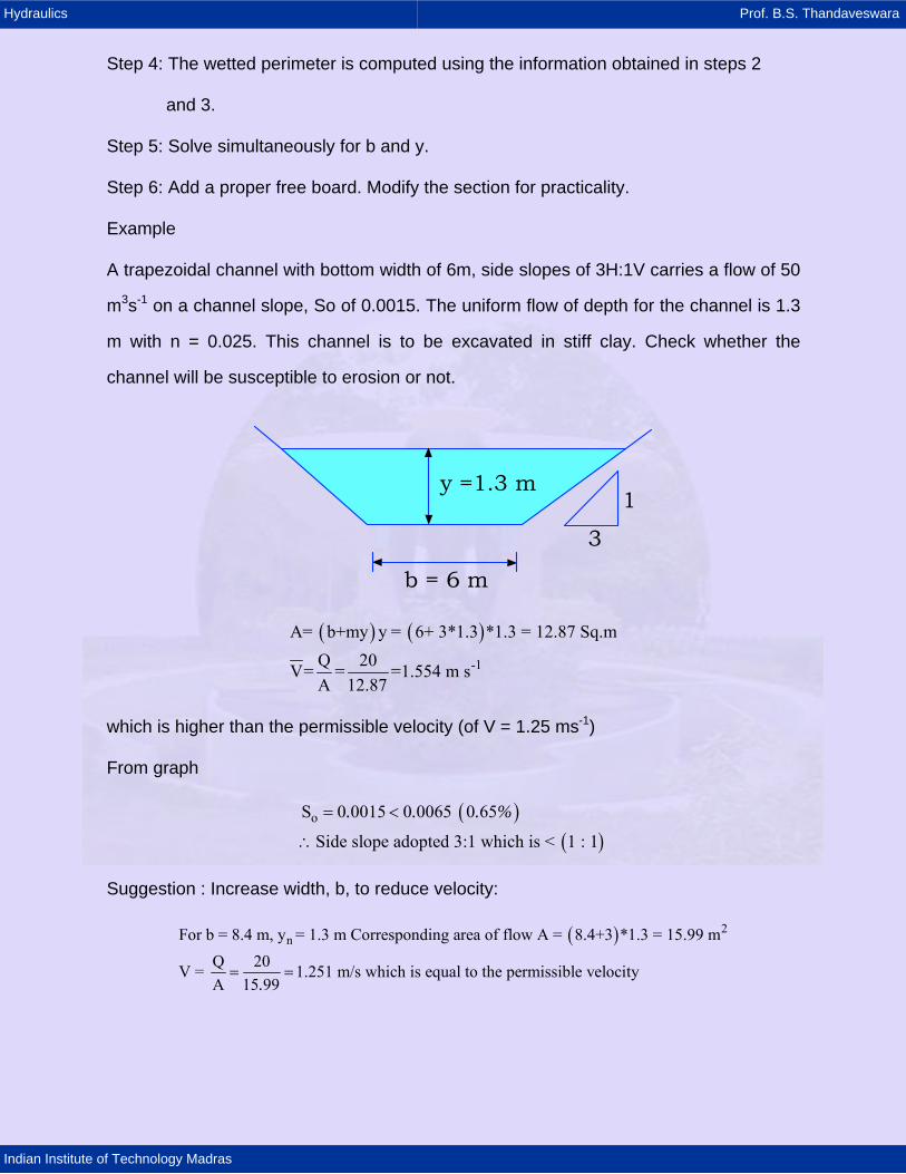
A trapezoidal channel with bottom width of 6m, side slopes of 3H:1V carries a flow of 50
m3s-1 on a channel slope, So of 0.0015. The uniform flow of depth for the channel is 1.3
m with n = 0.025. This channel is to be excavated in stiff clay. Check whether the
channel will be susceptible to erosion or not.
y =1.3 m
b = 6 m
1
3
( ) ( )-1
A= b+my y = 6+ 3*1.3 *1.3 = 12.87 Sq.mQ 20V= = =1.554 m sA 12.87
which is higher than the permissible velocity (of V = 1.25 ms-1)
From graph
( )( )
oS 0 0015 0 0065 0 65
Side slope adopted 3:1 which is < 1 : 1
. . . %= <
∴
Suggestion : Increase width, b, to reduce velocity:
( ) 2nFor b = 8.4 m, y = 1.3 m Corresponding area of flow A = 8.4+3 *1.3 = 15.99 m
Q 20V = 1.251 m/s which is equal to the permissible velocityA 15 99.= =
Hydraulics Prof. B.S. Thandaveswara
Indian Institute of Technology Madras
21.1.5 Method of Tractive Force
However, a design methodology based primarily on experience and observation rather
than physical principles. The first step in developing a rational design process for
unlined, stable, earthen channels is to examine the forces which cause scour. Scour on
the perimeter of a channel occurs when the particles on the perimeter are subjected to
forces of sufficient magnitude to cause particle movement. when a partical rests on the
level bottom of a channel, the force acting to cause movement is the result on the flow
of water past the particle. A particle rests on the slope side of a channel is acted on not
only by the flow - generated forces, but also by a gravitational component which tends
to make the particle roll or slide down the slope. If the resultant of those two forces is
larger than the forces resisting movement, gravity, and cohesion, then erosion of the
channel perimeter occurs. By definition, the tractive force is the force acting on the
partical composing the perimeter of the channel and is the result of the flow of water
past these particles. In parctice, the tractive force is not the force acting on a single
particle, but the force exerted over a certain area of the channel perimeter. This concept
was first stated by duBoys( 1879 ) and restated by Lane ( 1955 ).
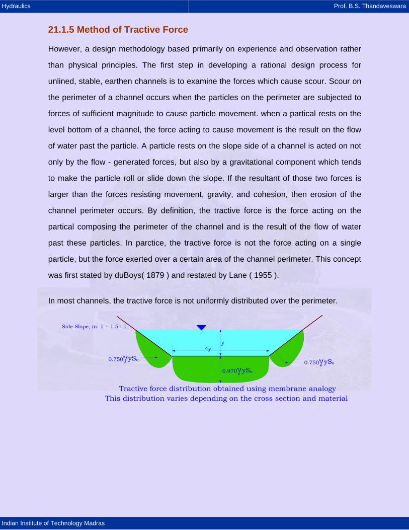
In most channels, the tractive force is not uniformly distributed over the perimeter.
0.750γySo 0.750γySo
0.970γySo
y4y
Side Slope, m: 1 = 1.5 : 1
Tractive force distribution obtained using membrane analogyThis distribution varies depending on the cross section and material
Hydraulics Prof. B.S. Thandaveswara
Indian Institute of Technology Madras
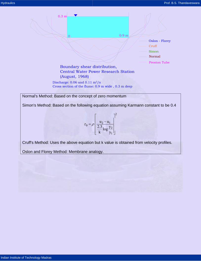
Oslon - FloreyCruff
SimonNormal
Preston Tube
0 0.9 m
0.3 m
Boundary shear distribution, Central Water Power Research Station(August, 1968)
Discharge: 0.06 and 0.11 m3/sCross section of the flume: 0.9 m wide , 0.3 m deep
Normal's Method: Based on the concept of zero momentum
Simon's Method: Based on the following equation assuming Karmann constant to be 0.4
2
2 10
2
1
u uy2.3 log
k y
τ ρ
⎡ ⎤⎢ ⎥−⎢ ⎥=⎢ ⎥⎢ ⎥⎣ ⎦
Cruff's Method: Uses the above equation but k value is obtained from velocity profiles.
Oslon and Florey Method: Membrane analogy.
Hydraulics Prof. B.S. Thandaveswara
Indian Institute of Technology Madras
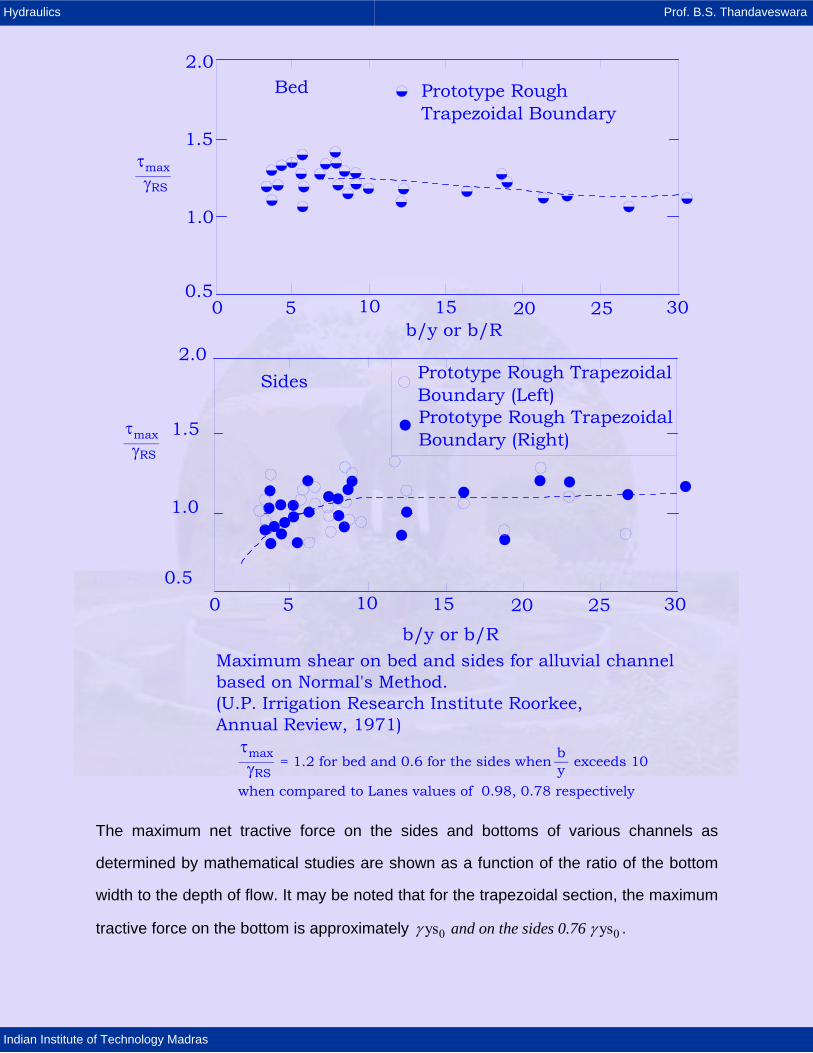
Prototype Rough Trapezoidal Boundary
Bed
0 5 10 15 20 25 300.5
1.0
1.5
2.0
b/y or b/R
τγmax
RS______
Prototype Rough TrapezoidalBoundary (Left)Prototype Rough TrapezoidalBoundary (Right)
0 5 10 15 20 25 30
Maximum shear on bed and sides for alluvial channelbased on Normal's Method.(U.P. Irrigation Research Institute Roorkee,Annual Review, 1971)
0.5
1.0
1.5
2.0Sides
b/y or b/R
τγmax
RS______
τγmax
RS______ = 1.2 for bed and 0.6 for the sides when exceeds 10 b__
ywhen compared to Lanes values of 0.98, 0.78 respectively
The maximum net tractive force on the sides and bottoms of various channels as
determined by mathematical studies are shown as a function of the ratio of the bottom
width to the depth of flow. It may be noted that for the trapezoidal section, the maximum
tractive force on the bottom is approximately 0 0ys ys and on the sides 0.76 γ γ .
Hydraulics Prof. B.S. Thandaveswara
Indian Institute of Technology Madras
The figures show the maximum unit tractive forces in terms of 0ysγ for different by
ratios.
Maximum unit tractive forces in terms of γySOn sides of channels On bottoms of channels
b/y b/y
Rectangle
Trapezoidal, m = 1
Trapezoidal, m = 2
Trapezoidal, m = 1.5
Trapezoidal, m = 2 and 1.5
Rectangle
0 1 32 4 5 6 7 8 9 100 1 32 4 5 6 7 8 9 100
0.1
0.2
0.3
0.4
0.5
0.6
0.7
0.8
0.9
1.0
0
0.1
0.2
0.3
0.4
0.5
0.6
0.7
0.8
0.9
1.0
0 When a particle on the perimeter of a channel is in a state of impending motion, the
forces acting to cause motion are in equilibrium with the forces resisting motion. A
particle on the level bottom of a channel is subject to the unit tractive force on a level
surface and effective area.
Hydraulics Prof. B.S. Thandaveswara
Indian Institute of Technology Madras
0.1 0.2 0.3 0.4 0.6 0.8 1.0 2.0 3.0 4.020
22
24
26
28
30
32
34
36
38
40
42
Particles size in inches (1 inch = 25.4 mm)
Angles repose for non cohesive material
inches
mm
In the above figure the particle size is the diameter of the particle of which 25 percent of
all the particals, measured by weight, are larger.
Lane ( 1955 ) also recognized that sinuous canals scour more easily than canals with
straight alignments. To account for this observation in the tractive force design method,
Lane developed the following definitions.
Straight canals have straight or slightly curved alinments and are typical of canals built
in flat plains.Slightly undulating topography.
Moderately sinuous canals have a degree of curvature which is typical of moderately
rolling topography.
Very sinuous canals have a degree of curvature which is typical of canals in foothills or
mountainous topography. Then, with these definitions, correction factors can be defined
as in Table.
Hydraulics Prof. B.S. Thandaveswara
Indian Institute of Technology Madras
Degree of sinuousness (stream length/ valley length)
Correction Factor
Straight Channels 1.00 Slightly Sinuous Channels 0.90 Moderately Sinuous Channels 0.75 Very Sinuous Channels 0.60
Reference
Craig Fischenich "Stability Thresholds for Stream Restoration Materials", May 2001.
10
2030405060708090
100
200
300
400500600700800900
1000
2000
3000400050006000700080009000
10000
20000
0.1 0.2 0.3 0.4 0.5 1 2 3 4 5 6 7 8 9 10 20 30 40 50 60 70 80 90
0.0030.0040.0050.0060.0070.0080.0090.01
4
3
2
10.90.80.70.60.50.40.30.2
0.10.090.0.
0807
0.06
0.05
0.040.030.02
Fortier & Scobey - Recommended for canals in fine sandwith water containing colloids Line representing relations of tractive forces b/ft2 = 0.5
Diameter in inchesTractive force kg/m2 = diameter in centimeters (approx)
Recommended value forcanals with high content offine sediment in the water
Schoklltach - Recommendedfor canals in sand
U.S.S.R. Canals with2.5 % colloids in water
NUERNBURG KULTURAMPT (NK)
Fortier & Scobey - Recommended for canals, in fine sand and clear water
Recommended values for canals with clear water
Stroub values of critical forceU.S.S.R. Canals with clear water
Recommended values for canalswith low content of fine sedimentin the water
Recommended values for canals incoarse, non-cohesive material size25% or larger
U.S.S.R.Canals with0.1% colloidsin water
NK
MEAN DIAMETER, MILLIMETERS
DESIGN OF SMALL DAMS USBR' 87
NK
Conversion Factor 2 21 lb / ft 47.87 N / m =
Plasticity index (PI) is the difference in percentage of moisture between plastic limit and
liquid limit in Atterberg soil tests. For canal design PI can be taken as 7 as the critical
value. In this figure, for the fine non cohesive , i.e.,average diameters less than 5mm ,
the size specified is the median size of the diameter of a partical of which 50 percent
were larger by weight. Lacey developed the following equations based on the analysis
of large amount of data collected on several irrigation canals in the India.
Hydraulics Prof. B.S. Thandaveswara
Indian Institute of Technology Madras
1/ 2s
1/ 3
s
4 5 / 3 1/ 60 s
P 4.75 Q
f 1.76 d
QR 0.47f
S 3*10 f Q
−
=
=
⎛ ⎞= ⎜ ⎟
⎝ ⎠=
In which P is the wetted perimeter (m), R is the hydraulic mean radius (m), Q is the flow
in m3/s, d is the diameter of the sediment in mm, fs is the silt factor, S0 is the bed slope.
Table: particle size and silt factors for various materials
Material Size (mm) Silt factor Small boulders, cobbles, shingles 64 - 256 6.12 to 9.75
Coarse gravel 8-64 4.68 Fine gravel 4-8 2.0 Coarse sand 0.5-2.0 1.44 - 1.56 Medium sand 0.25-0.5 1.31 Fine sand 0.06-0.25 1.1 - 1.3 Silt (colloidal) 1.0 Fine silt (colloidal) 0.4 - 0.9
Taken from Gupta (1989)
Combining the above equations the following resistance equations similar to the
Manning equation based on the regime theory is obtained.
2/ 3 1/30V 10.8 R S = in which V is the velocity in m/s.
21.1.6 The Tractive Force Method
When water flows in a channel, a force that acts in the direction of flow on the channel
bed is developed. This force, which is nothing but the drag of water on the wetted area
and is known as the tractive force. A particle on the sloping side of a channel is subject
to both a tractive force and a downslope gravitational component. It is noted that the
tractive force ratio is a function of both the side slope angle and the angle of repose of
the material composing the channel perimeter.In the case of cohesive materials and fine
noncohesive materials, the angle of repose is small and can be assumed to be zero;
Hydraulics Prof. B.S. Thandaveswara
Indian Institute of Technology Madras
i.e.. for these materials the forces of cohesion are significantly larger than the
gravitational component tending to make the particles roll downslope.
Consider the shear stress at incipient motion (which just begins to move particles) for
uniform flow.
The tractive force is equal to the gravity force component acting on the body of water,
parallel to the channel bed.
Gravity component of weight of water in the direction of flow is equal to 0ALSγ in
which, γ is the unit weight of water, A is the wetted area, L is the length of the channel
reach, and S0 is the slope. Thus, the average value of the tractive force per unit wetted
area, is equal to 00
ALS RSPL 0
γτ = = γ , in which P is the wetted perimeter and R is the
hydraulic mean radius; For wide rectangular channel, it can be written as 0 0ySτ γ=
The tractive force is also called Drag Force.
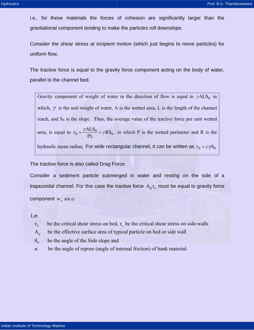
Consider a sediment particle submerged in water and resting on the side of a
trapezoidal channel. For this case the tractive force p sA τ must be equal to gravity force
component sw sin α
b s
p
0
Let τ be the critical shear stress on bed, τ be the critical shear stress on side-walls A be the effective surface area of typical particle on bed or side wall
θ be the angle of the Side slope and α be the angle of repose (angle of internal friction) of bank material.
Hydraulics Prof. B.S. Thandaveswara
Indian Institute of Technology Madras
τsAp
τbAp
myb/2
Plan View
LC
Flow
Ws = submerged weight of the particle
θ0Ws
On the surface of the side slope
θ0 θ0
y
Hydraulics Prof. B.S. Thandaveswara
Indian Institute of Technology Madras
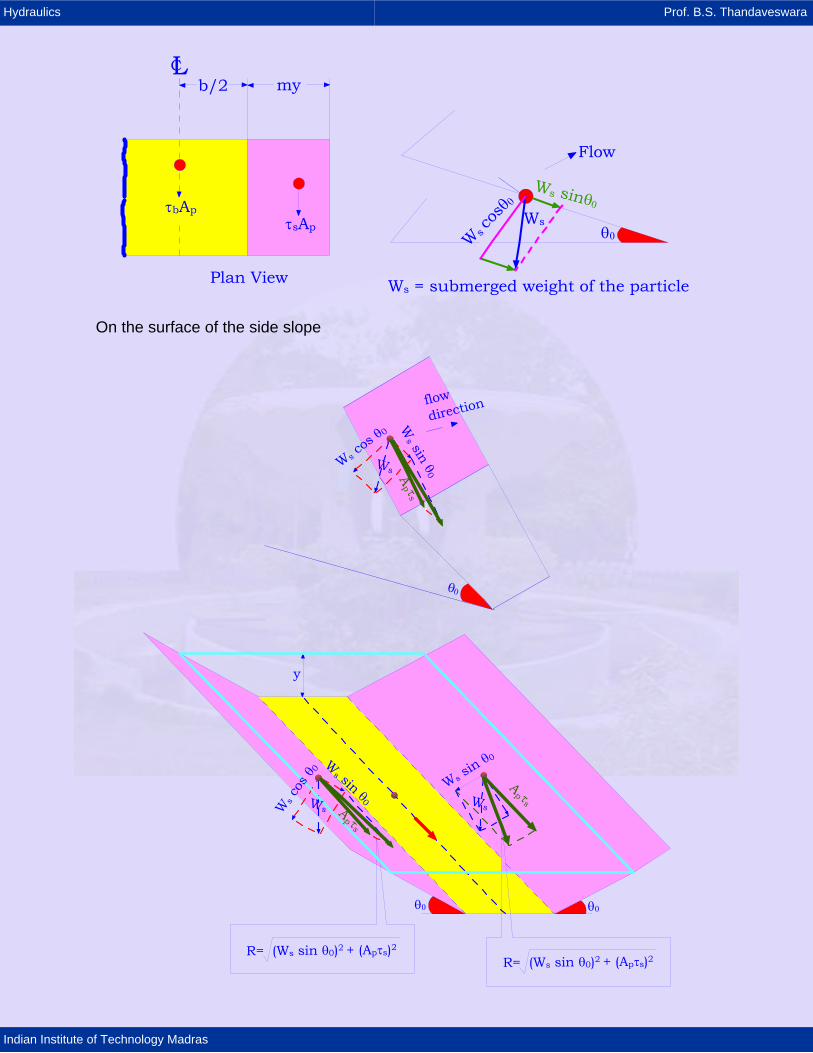
From Force diagram, resultant Force, R:
( ) ( )22s 0 p sR W sinθ + A τ=
Resisting Force, Fs:
( )s 0
s s 0
W cosθ is the weight component normal to side slopetanα is the coefficient of friction due to angle of internal frictionF W cos θ tanα=
Therefore
s
2 2 2s 0 s 0 p
2s 0
s 0 2p
R F at incipient motion.
W cos θ tan W sin θ A
for the unit tractive force that causes impending motion on a sloping surface
W tan θτ tan cos θ 1- A tan α
s
sSolving
α τ
τ
α
=
= +
∴ =
On the channel bed, with being zero it reduces to 0θ
sp b s b
p
W tanαA τ W tanα τA
= → =
Tractive Force Ratio
2 2s
2 2b 0 0
τ sinK 1 1- τ sin
tancostan
α ααθ θ
= = − =
K is the reduction factor of critical stress on the channel side.
Thus the ratio is a function of only side slope angle and angle of repose of the
material
0θ
α .

Hydraulics Prof. B.S. Thandaveswara
Indian Institute of Technology Madras
Example:
Canal cross section: World's largest canalFull supply level at Head Regulator 91.44 mLength upto Rajasthan border 458.00 kmLength in Rajasthan 74.00 km
3 -1
Total 532 km
Bed width at head reach 73.1 mFully supply depth at head reach 7.60 m
Design discharge(head reach) 1133 m s
Gujar 3 -1ath - Rajasthan border 71m sNo. of branches 42Length of distribution Network 66000 kmconcrete lining of 100 mm to 125 mm concrete
Total LiningPhase
5
3 -1
I 150.58 + 93.93 + 39.26 = 283.77Phase II 126.14 + 1.08 +22.60 = 149.82
Total = 435.59 x 10 Sq.m
2) Sardar Sarovar Project
design disharge 86937.2 m s will be the 3rd largest in the world.
Gaz 5 3 -1
5 3 -1
enba, china 1.13 x 10 m s
Tucurri Brazil 1.0 x 10 m sRadial gates of chute spillway 7 nos 18.3m x 18.3mFor sertvice spillway 23 radial gates of 18.3m x 16.75.Dam is 12.0 m concrete gravity damHei
3
ght of dam from foundary 163.00 m
Gross storage 9497.07 m
The design procedure for flexible lining channel consists of following steps:
1. Channels are usually trapezoidal or triangular (with rounded corners) or parabolic.
2. If lined with rip-rap, m > 3, no need to check for blank stability.
3. Channel slopes can be steep depending on application.
4. Most flexible linings give adequate protection upto 0S 0.01≈ .
Hydraulics Prof. B.S. Thandaveswara
Indian Institute of Technology Madras
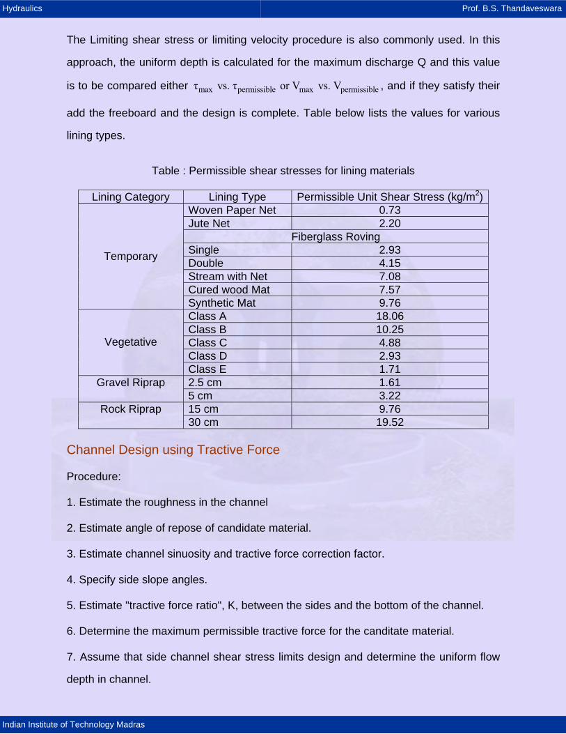
The Limiting shear stress or limiting velocity procedure is also commonly used. In this
approach, the uniform depth is calculated for the maximum discharge Q and this value
is to be compared either , and if they satisfy their
add the freeboard and the design is complete. Table below lists the values for various
lining types.
max permissible max permissibleτ vs. τ or V vs. V
Table : Permissible shear stresses for lining materials
Lining Category Lining Type Permissible Unit Shear Stress (kg/m2)Woven Paper Net 0.73 Jute Net 2.20
Fiberglass Roving Single 2.93 Double 4.15 Stream with Net 7.08 Cured wood Mat 7.57
Temporary
Synthetic Mat 9.76 Class A 18.06 Class B 10.25 Class C 4.88 Class D 2.93
Vegetative
Class E 1.71 2.5 cm 1.61 Gravel Riprap 5 cm 3.22 15 cm 9.76 Rock Riprap 30 cm 19.52
Channel Design using Tractive Force
Procedure:
1. Estimate the roughness in the channel
2. Estimate angle of repose of candidate material.
3. Estimate channel sinuosity and tractive force correction factor.
4. Specify side slope angles.
5. Estimate "tractive force ratio", K, between the sides and the bottom of the channel.
6. Determine the maximum permissible tractive force for the canditate material.
7. Assume that side channel shear stress limits design and determine the uniform flow
depth in channel.
Hydraulics Prof. B.S. Thandaveswara
Indian Institute of Technology Madras
8. Calculate the required bottom width.
9. Check that the permissible tractive force is not exceeded on channel bed.
10. Check that the design velocity exceeds the minimum permitted velocity (usually 0.6
to 0.9 m/s) and check the Froude number of the flow (F= subcritical).
11. Estimate the required freeboard.
Example:
1. Design a trapezoidal channel to carry 20 m3/s through a slightly sinuous channel on a
slope of 0.0015. The channel is to be excavated in coarse alluvium with a 75 percentile
diameter of 2 cm of moderately rounded particles.
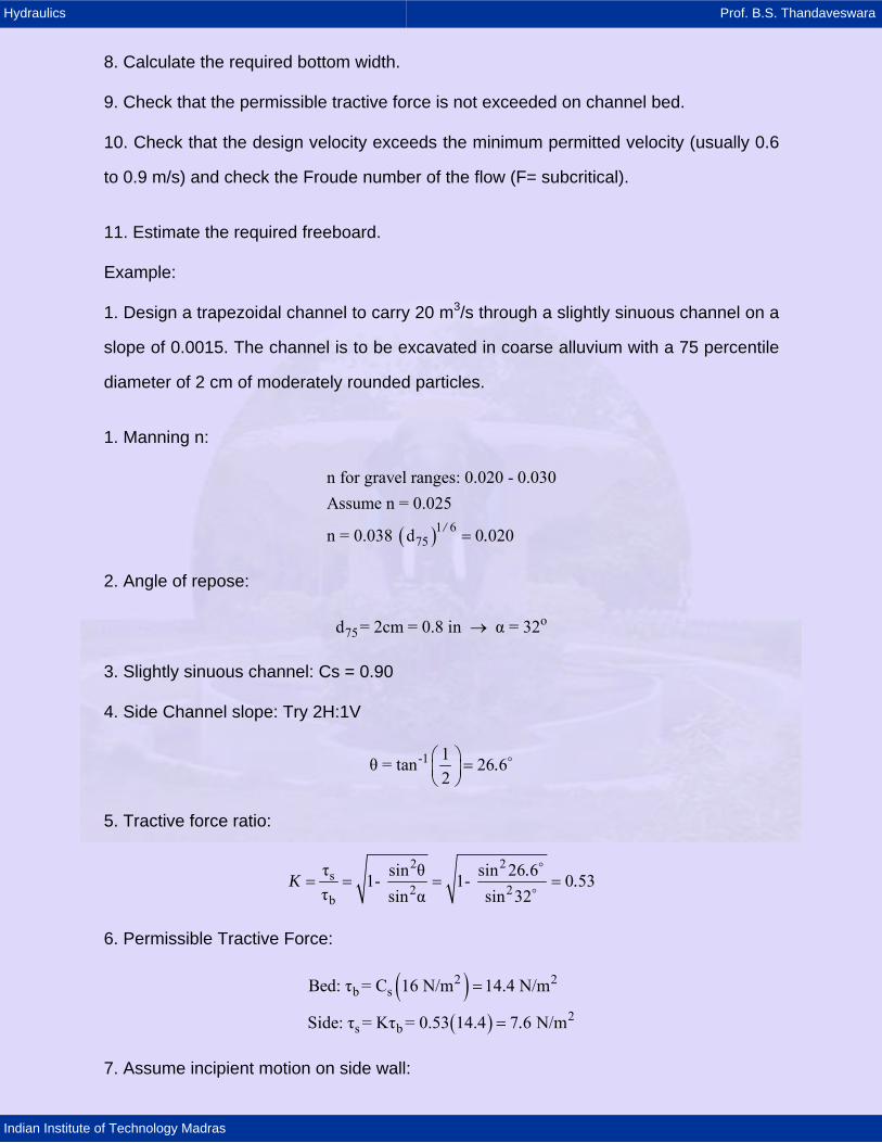
1. Manning n:
( )1 675
n for gravel ranges: 0.020 - 0.030Assume n = 0.025
n = 0.038 d 0 020/ .=
2. Angle of repose:
o75d = 2cm = 0.8 in α = 32→
3. Slightly sinuous channel: Cs = 0.90
4. Side Channel slope: Try 2H:1V
-1 1θ = tan 26 62
.⎛ ⎞ =⎜ ⎟⎝ ⎠
5. Tractive force ratio:
2 2s
2 2b
τ sin θ sin 26 61- 1- 0 53τ sin α sin 32
.K .= = = =
6. Permissible Tractive Force:
( )( )
2 2b s
2s b
Bed: τ = C 16 N/m 14.4 N/m
Side: τ = Kτ = 0.53 14.4 7 6 N/m.
=
=
7. Assume incipient motion on side wall:
Hydraulics Prof. B.S. Thandaveswara
Indian Institute of Technology Madras
( )( )
2s o o
sn
o
τ 0 76γ y S = 7.6 N/mτ 7 6 y 0.68 m
0 76γ S 0 76 9790 0 0015
..
. . .
=
= = =
8. Solve for bottom width b:
( )
5/32/3 1 2 1 2
0 02/3
2 2
1 1 AQ = AR S Sn n P
where A=by+my , P= b+2y 1+mb = 2.42m smallest positive real solution
/ /=
9. Tractive force on bed:
( )( )( ) 2b 0 0
2 2
τ 0 97 γ y S 0 97 γ 0 68 0 0015 9 7 N/m
1 7 N/m 14 4 N/m
. . . . .
. .
= = =
<
10. Check velocities:
( )( ) ( )22 2Area = by + my = 24.2 0.68 2 0.68 17 4 mQ 20V = 1 1 m/sA 17.4V VF=gD Ag
BT = Top width = T+2 my = 26.92 mD = A/T = 0.65 mFroude number = 0.44
.
.
+ =
= =
=⎛ ⎞⎜ ⎟⎝ ⎠
11. Free board:
3For Q = 20 m /s the freeboard will be 0.75 mTotal depth = 0.68 + 0.75=1.43 m
2. Design a straight trapezoidal channel for a design discharge of 20 m3/s. The bed
slope 0.00025 and channel is excavated through the fine grave having particle size of 8
mm. Assume the material to be rounded moderately and water has low concentration of
sediment. Q = 10 m3/s, S0 = 0.00025, moderately rounded. Diameter = 8 mm =
8 0 314925 4
. ".= .
For fine gravel n = 0.025 is assumed
Hydraulics Prof. B.S. Thandaveswara
Indian Institute of Technology Madras
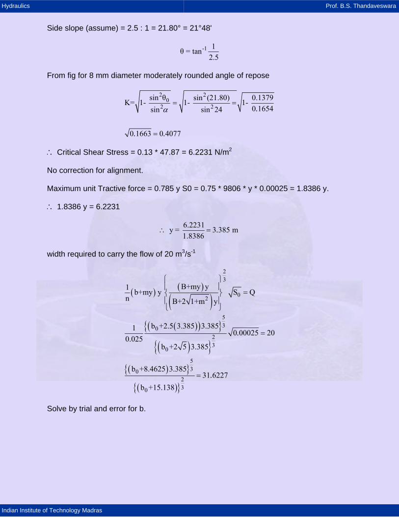
Side slope (assume) = 2.5 : 1 = 21.80° = 21°48'
-1 1θ = tan2.5
From fig for 8 mm diameter moderately rounded angle of repose
2 20
2 2sin θ sin (21.80) 0.1379K= 1- 1- 1-
0 1654sin sin 24
0 1663 0 4077
.
. .
α= =
=
∴ Critical Shear Stress = 0.13 * 47.87 = 6.2231 N/m2
No correction for alignment.
Maximum unit Tractive force = 0.785 y S0 = 0.75 * 9806 * y * 0.00025 = 1.8386 y.
∴ 1.8386 y = 6.2231
6.2231y = 3 385 m1.8386
.∴ =
width required to carry the flow of 20 m3/s-1
( ) ( )
( )( )( ){ }
( ){ }( ){ }
( ){ }
23
02
530
23
0
530
230
B+my y1 b+my y S Qn B+2 1+m y
b +2.5 3.385 3.3851 0 00025 200.025
b +2 5 3.385
b +8.4625 3.38531 6227
b +15.138
.
.
⎧ ⎫⎪ ⎪
=⎨ ⎬⎪ ⎪⎩ ⎭
=
=
Solve by trial and error for b.
Hydraulics Prof. B.S. Thandaveswara
Indian Institute of Technology Madras
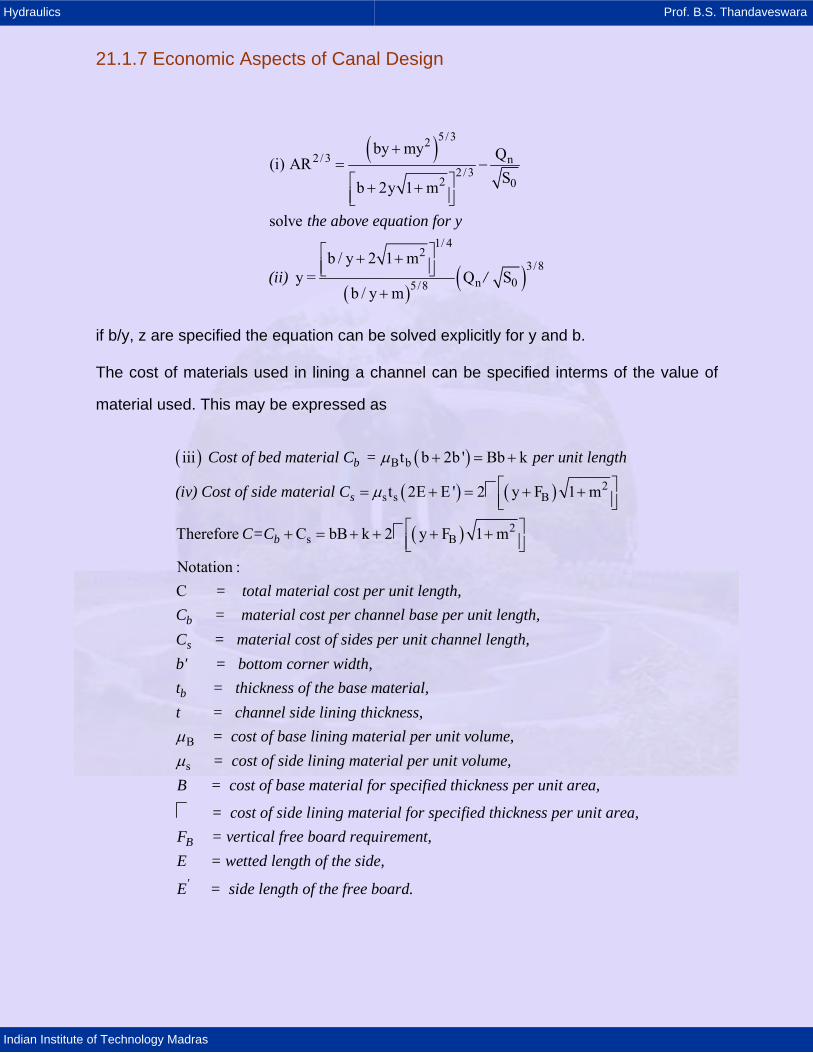
21.1.7 Economic Aspects of Canal Design
( )
( )( )
5/322/ 3 n
2 /32 0
1/ 42
3/8n 05/8
by my Q(i) ARSb 2y 1 m
solve
b / y 2 1 my = Q S
b / y m
+= −⎡ ⎤+ +⎢ ⎥⎣ ⎦
⎡ ⎤+ +⎢ ⎥⎣ ⎦+
the above equation for y
(ii) /
if b/y, z are specified the equation can be solved explicitly for y and b.
The cost of materials used in lining a channel can be specified interms of the value of
material used. This may be expressed as
( ) ( )
( ) ( )
( )
B b
2s s B
2s B
iii t b 2b ' Bb k
t 2E E ' 2 y F 1 m
Therefore C bB k 2 y F 1 m
Notation :C
b
s
b
Cost of bed material C = per unit length
(iv) Cost of side material C
C=C
= total material cost per un
µ
µ
+ = +
⎡ ⎤= + = + +⎢ ⎥⎣ ⎦⎡ ⎤+ = + + + +⎢ ⎥⎣ ⎦
b
s
b
it length,C = material cost per channel base per unit length,C = material cost of sides per unit channel length,b' = bottom corner width,t = thickness of the base materi
B
s
al,t = channel side lining thickness,
= cost of base lining material per unit volume, = cost of side lining material per unit volume,
B = cost of base material for specified
µµ
B
'
thickness per unit area,
= cost of side lining material for specified thickness per unit area,F = vertical free board requirement,E = wetted length of the side,
E = side length of the free board.
Hydraulics Prof. B.S. Thandaveswara
Indian Institute of Technology Madras
Minimum Cost Trapezoidal Section by Optimisation Technique
Lagrange Multiplier technique can be used. Ratio of marginal changes in section factor
are equal to the marginal changes in the costs i.e.
( )
( )
2 / 3
2 / 3
AR Cb b
CARy
y
∂ ∂∂ ∂=
∂∂∂
∂
The above equation represents the minimum cost of the optimal cost subject to the
equation. Substituting, then the optimal solution of the above is given by,
( )
2
1 2 3
2 21
22
3
11/ 2
22 2 1
y yK K K 0b b
BK 20 z 1 1 4 4z z 1
B BK 1 6z z 1 10z
BK 5 then,
2Kby BK K 20 K
which is a function of z and the ratio of the unit costs of the bas
⎛ ⎞ ⎛ ⎞+ + =⎜ ⎟ ⎜ ⎟⎝ ⎠ ⎝ ⎠
⎡ ⎤⎛ ⎞= + − + +⎜ ⎟⎢ ⎥⎝ ⎠⎣ ⎦⎡ ⎤⎛ ⎞ ⎛ ⎞= − + −⎜ ⎟ ⎜ ⎟⎢ ⎥⎝ ⎠ ⎝ ⎠⎣ ⎦
= −
=⎡ ⎤− + +⎢ ⎥⎣ ⎦
0
e to side slope material viz;
B Unit Cost of Base MaterialUnit Cost of Side Material
SolutionSteps
1. S , B, , n, z and Q are given. Determine K1, K2, and K3.
2. Estimate b/y for minimum cost using equati
=
on.
3. Estimate the minimum cost depth of flow using equation.
4. Obtain the minimum cost bottom width by multiplying y times the ratio of b/y.
5. Generate the graphs for y Vs b for different values of B0
n/Q/ and for a given value of z.S
6. Also study the sensitivity of lining cost to variations of side slope (or side slope ratios).
Hydraulics Prof. B.S. Thandaveswara
Indian Institute of Technology Madras
Sample Run
Data
s BQ in cumecs, B, and k in R , F in m0.08, 0.001, 0.014, 0.50, 105.0, 65.0, 15.0, 0.15ResultMinimum Lining cost per unit Length = Rs. 109.51Minimum cost bottom width = 0.186 mMinimum cost depth of flo
( ) ( )
( ) ( )( )
( )( )
( )
1
2
3
2
w = 0.366 m105K 20 0.25 1 1 4 4 0.50 1 0.25 8.318965
105K 1 6 1 0.25 10 0.50 1.615 12.200565
K 5 1.615 8.075
2 8.315by 12.20 12.25 20 1.615 8.315
⎛ ⎞= + − + + =⎜ ⎟⎝ ⎠
⎡ ⎤⎛ ⎞= − + − = −⎜ ⎟⎢ ⎥⎝ ⎠⎣ ⎦= − = −
=⎡ ⎤+ +⎣ ⎦
References
1. Hager, W.H. 1985, Modified venturi channel. Journal of the Irrigation and Drainage
Engineering, ASCE, 3(1): 19-35.
2. Hager, W.H. and P.U. Volkart, 1986, Distribution channels, Journal of Hydraulic
Engineering, ASCE, 112(10): 935-952.
3. Trout T.J., "Channel Design to minimise lining material cost" J. of Irrigation and
Drainage Division Division, ASCE Vol. 105, Dec 1982, pp 242 - 245.
21.1.8 Seepage in Canal
Introduction
Seepage is one of the most serious forms of water loss in an irrigation canal network.
Water lost by seepage cannot be recovered without the use of costly pumping plant. In
addition excessive seepage losses can cause low lying areas of land to become
unworkable. As the water table rises, water logging and soil salinisation can occur,
Hydraulics Prof. B.S. Thandaveswara
Indian Institute of Technology Madras
necessitating the installation of elaborate and costly drainage systems. Furthermore the
cultivable area is reduced, resulting in a loss of potential crop production.
The accurate measurement of seepage in existing irrigation canals enables very
previous reaches to be identified and lined to conserve water; losses amounting to as
much as 40% of the total inflow to a scheme have been recorded. Moreover valuable
information about the long term performance of different types of canal linings in general
use can be obtained, enabling conveying efficiencies to be improved in the future.
Three methods of seepage measurement are in common use at the present, namely:
ponding; inflow/outflow; seepage meter. Other methods of seepage detection are also
used, such as for example, chemical tracers, radioactive tracers, piezometric surveys,
electrical borehole logging, surface resistivity measurements, and remote sensing.
These methods suffer from the disadvantage that they are either more difficult to use or
interpret.
Ponding Method
Ponding is considered to be the most accurate method of seepage measurement. It is
frequently used as standard with which to compare other methods. The procedure, in
principle is simple, a stretch of canal under investigation is isolated and filled with water.
The rate of seepage is determined by one of two methods. In the first, which is the one
usually employed, the rate of fall of the water level is recorded (falling level method).
Alternatively, the rate at which the water must be added to keep the water level constant
is recorded, (constant level method).
In practice the ponding method has certain advantages:
1. The accuracy of measurement is not dependent on the length of the test reach
provided it is sufficient to compensate for normal errors.
2. The requirement for trained manpower is small.
3. Sophisticated equipment is not required for the test.
Hydraulics Prof. B.S. Thandaveswara
Indian Institute of Technology Madras
The disadvantages of the method are
1. Costly bulkheads must be built at each end of the reach if existing structures are not
available.
2. The normal flow through the canal must be stopped for the duration of the test.
Hence the methods is usually restricted to smaller canals.
3. The rate of seepage loss from the test section can vary with time because of the
sealing effect of fine material settling out in the water, or in the case of a canal which is
initially dry, because of the time taken to re saturate, or a combination of both.
4. The rate of seepage loss can be very different from that measured in the canal in
flowing water because of 3.
5. Large quantities of water are required if the canal under test is initially dry.
Inflow / Outflow Method
Next to ponding, inflow/ outflow, is the most commonly used method for the
measurement of seepage. The discharges into, and out of a selection reach of a river or
canal are measured. the rate of seepage is derived from the difference. In comparison
with the ponding method, the inflow/ outflow method has certain advantages:
1. Any impedance to the normal operation of the canal os minimised.
2. No costly bulkheads are required.
3. Seepage is measured with the canal in its normal discharge state, thus eliminating
the effects of silting, algae and fungoidal growth, and distortion of the local seepage
flow.
4. Measurements can be made even when numerous off takes are spread without too
great an increase in overall cost.
The disadvantage of the method on the other hand are
Hydraulics Prof. B.S. Thandaveswara
Indian Institute of Technology Madras
1. The errors in the flow measurement tend to overshadow the seepage losses,
especially in large canals greatly reducing its accuracy.
2. Measurement becomes very labour intensive if a large number of off takes are
present.
3. Only the bulk measurement of seepage, over the test reach is obtained, which can
attain a considerable length because of 4. In large canals very large reaches are
required to improve the accuracy of an individual measurement because of 1. Various
methods are available for the measurement of a canal or river discharge. These can be
divided into two classes: Continuous methods; Occasional methods. Only gauging
structures, ultra-sonic, and electro-magnetic, among the Continuous methods, and
velocity area, and dilution gauging among the Occasional methods are considered to be
potentially accurate enough for the estimation of seepage. Each of these techniques is
outlined briefly below in the context of the inflow/ outflow method.
Velocity Area Method
This method is the mostly used of all discharge measurement techniques. The area of
flow is determined by sounding, and the mean velocity by current metering. The product
of the two giving the discharge. Some care must be taken when selecting a site on a
canal or river however. Ideally the test reach should be straight and free from
obstructions, weeds, or off takes, and have a stable bed. Before beginning a discharge
measurement, a preliminary survey should be carried out to determine the bed profile,
and to ensure that a well-developed velocity distribution exists along the channel. All
soundings should be related to an established datum.
The method of current metering depends on the depth of flow and velocity, ranging from
the use of wading rods to a cable car suspended across the channel. For most gauging
work on irrigation canals however the current metering is usually carried out either with
wading rods of from boat. The accuracy of the measurement depends firstly on a
Hydraulics Prof. B.S. Thandaveswara
Indian Institute of Technology Madras
number of verticals at which velocity readings are taken and to a lesser extent on the
number of levels velocities are measured at on each vertical.
The achievable accuracy can be optimised with the available equipment, time, and
manpower. The length of time given to each current meter reading depends very much
on flow conditions, but during the preliminary tests it is advisable to record for the
recommended 3 minutes while taking readings after each minute for comparison. If very
accurate results are required it is essential that the survey is carried out by an
experienced, well-trained team.
The inflow/ outflow method is very sensitive to canal size.