2103 / 2103ci/gi modem module - teledyne isco · 3.2 magnetic mount antenna. . . . . . . . . . . ....
TRANSCRIPT

2103Ci/GiModem Module
Installation and Operation Guide
Part #69-2003-637 of Assembly #60-2004-637Copyright © 2011. All rights reserved, Teledyne Instruments, Inc.Revision E, August 2016


Foreword
This instruction manual is designed to help you gain a thorough understanding of the operation ofthe equipment. Teledyne Isco recommends that you read this manual completely before placing theequipment in service.
Although Teledyne Isco designs reliability into all equipment, there is always the possibility of amalfunction. This manual may help in diagnosing and repairing the malfunction.
If a problem persists, call or e-mail Teledyne Isco technical support for assistance. Simpledifficulties can often be diagnosed over the phone. For faster service, please have your serialnumber ready.
If it is necessary to return the equipment to the factory for service, please follow the shippinginstructions provided by technical support, including the use of the Return MaterialAuthorization (RMA) specified. Be sure to include a note describing the malfunction. This willaid in the prompt repair and return of the equipment.
Teledyne Isco welcomes suggestions that would improve the information presented in this manualor enhance the operation of the equipment itself.
Teledyne Isco is continually improving its products and reserves the right to change productspecifications, replacement parts, schematics, and instructions without notice.
Contact Information
Customer Service
Phone: (800) 228-4373 (USA, Canada, Mexico)
(402) 464-0231 (Outside North America)
Fax: (402) 465-3022
Email: [email protected]
Technical Support
Phone: Toll Free (800) 775-2965 (Syringe Pumps and Liquid Chromatography)
Email: [email protected]
Return equipment to: 4700 Superior Street, Lincoln, NE 68504-1398
Other Correspondence
Mail to: P.O. Box 82531, Lincoln, NE 68501-2531
Email: [email protected]


iii
2103 Modem Module
Table of Contents
Section 1 Introduction
1.1 Product Description. . . . . . . . . . . . . . . . . . . . . . . . . . . . . . . . . . . . . . . . . . . . . . . . . . 1-11.2 2103Ci/Gi Module Components . . . . . . . . . . . . . . . . . . . . . . . . . . . . . . . . . . . . . . . . 1-21.3 Battery Module Components . . . . . . . . . . . . . . . . . . . . . . . . . . . . . . . . . . . . . . . . . . 1-41.4 Technical Specifications . . . . . . . . . . . . . . . . . . . . . . . . . . . . . . . . . . . . . . . . . . . . . . 1-61.5 Safety Symbols and Hazard Alerts . . . . . . . . . . . . . . . . . . . . . . . . . . . . . . . . . . . . . 1-91.6 Technical Service. . . . . . . . . . . . . . . . . . . . . . . . . . . . . . . . . . . . . . . . . . . . . . . . . . . . 1-9
Section 2 Preparation and Installation
2.1 Unpacking Instructions . . . . . . . . . . . . . . . . . . . . . . . . . . . . . . . . . . . . . . . . . . . . . . 2-12.2 System Power . . . . . . . . . . . . . . . . . . . . . . . . . . . . . . . . . . . . . . . . . . . . . . . . . . . . . . 2-22.3 Installation Preparation . . . . . . . . . . . . . . . . . . . . . . . . . . . . . . . . . . . . . . . . . . . . . . 2-3
2.3.1 Latches - Locking and Unlocking . . . . . . . . . . . . . . . . . . . . . . . . . . . . . . . . . 2-32.3.2 Communication Connectors . . . . . . . . . . . . . . . . . . . . . . . . . . . . . . . . . . . . . 2-52.3.3 Installing the Batteries . . . . . . . . . . . . . . . . . . . . . . . . . . . . . . . . . . . . . . . . . 2-6
2.4 Stacking Modules . . . . . . . . . . . . . . . . . . . . . . . . . . . . . . . . . . . . . . . . . . . . . . . . . . . 2-72.5 Connecting to Flowlink . . . . . . . . . . . . . . . . . . . . . . . . . . . . . . . . . . . . . . . . . . . . . . . 2-92.6 Modem Site Connection . . . . . . . . . . . . . . . . . . . . . . . . . . . . . . . . . . . . . . . . . . . . . 2-132.7 Power Conservation (cellular modules) . . . . . . . . . . . . . . . . . . . . . . . . . . . . . . . . . 2-152.8 Setting Up Text Alarms (cellular modules) . . . . . . . . . . . . . . . . . . . . . . . . . . . . . . 2-172.9 Pushed Data Capability
(cellular modules) . . . . . . . . . . . . . . . . . . . . . . . . . . . . . . . . . . . . . . . . . . . . . . . . . . 2-19
Section 3 2103Ci Cellular Modem Module
3.1 Overview . . . . . . . . . . . . . . . . . . . . . . . . . . . . . . . . . . . . . . . . . . . . . . . . . . . . . . . . . . 3-13.1.1 Data Retrieval . . . . . . . . . . . . . . . . . . . . . . . . . . . . . . . . . . . . . . . . . . . . . . . . 3-13.1.2 Text Messaging . . . . . . . . . . . . . . . . . . . . . . . . . . . . . . . . . . . . . . . . . . . . . . . 3-13.1.3 Stacking / Compatibility . . . . . . . . . . . . . . . . . . . . . . . . . . . . . . . . . . . . . . . . 3-13.1.4 Cellular Service . . . . . . . . . . . . . . . . . . . . . . . . . . . . . . . . . . . . . . . . . . . . . . . 3-13.1.5 2103Ci Label Information . . . . . . . . . . . . . . . . . . . . . . . . . . . . . . . . . . . . . . . 3-2
3.2 Magnetic Mount Antenna . . . . . . . . . . . . . . . . . . . . . . . . . . . . . . . . . . . . . . . . . . . . . 3-2
Section 4 2103Gi Cellular Modem Module
4.1 Overview . . . . . . . . . . . . . . . . . . . . . . . . . . . . . . . . . . . . . . . . . . . . . . . . . . . . . . . . . . 4-14.1.1 Data Retrieval . . . . . . . . . . . . . . . . . . . . . . . . . . . . . . . . . . . . . . . . . . . . . . . . 4-14.1.2 Text Messaging . . . . . . . . . . . . . . . . . . . . . . . . . . . . . . . . . . . . . . . . . . . . . . . 4-14.1.3 Stacking / Compatibility . . . . . . . . . . . . . . . . . . . . . . . . . . . . . . . . . . . . . . . . 4-1
4.2 SIM Card . . . . . . . . . . . . . . . . . . . . . . . . . . . . . . . . . . . . . . . . . . . . . . . . . . . . . . . . . . 4-14.3 Antenna Options . . . . . . . . . . . . . . . . . . . . . . . . . . . . . . . . . . . . . . . . . . . . . . . . . . . . 4-4
4.3.1 Magnetic Mount Antenna . . . . . . . . . . . . . . . . . . . . . . . . . . . . . . . . . . . . . . . 4-44.3.2 In-Street Antenna . . . . . . . . . . . . . . . . . . . . . . . . . . . . . . . . . . . . . . . . . . . . . 4-44.3.3 Manhole Lid-Mount Antenna . . . . . . . . . . . . . . . . . . . . . . . . . . . . . . . . . . . . 4-5

2103 Modem ModuleTable of Contents
iv
Section 5 Modbus Protocol
5.1 Introduction . . . . . . . . . . . . . . . . . . . . . . . . . . . . . . . . . . . . . . . . . . . . . . . . . . . . . . . . 5-15.2 Operation . . . . . . . . . . . . . . . . . . . . . . . . . . . . . . . . . . . . . . . . . . . . . . . . . . . . . . . . . . 5-1
5.2.1 Establishing Communication . . . . . . . . . . . . . . . . . . . . . . . . . . . . . . . . . . . . 5-25.2.2 Module Addressing . . . . . . . . . . . . . . . . . . . . . . . . . . . . . . . . . . . . . . . . . . . . 5-2
5.3 Configurations . . . . . . . . . . . . . . . . . . . . . . . . . . . . . . . . . . . . . . . . . . . . . . . . . . . . . . 5-35.4 Glossary of Terms . . . . . . . . . . . . . . . . . . . . . . . . . . . . . . . . . . . . . . . . . . . . . . . . . . . 5-45.5 Common Acronyms . . . . . . . . . . . . . . . . . . . . . . . . . . . . . . . . . . . . . . . . . . . . . . . . . . 5-55.6 Register Specifications - 2100 Output . . . . . . . . . . . . . . . . . . . . . . . . . . . . . . . . . . . 5-5
5.6.1 Register Addresses . . . . . . . . . . . . . . . . . . . . . . . . . . . . . . . . . . . . . . . . . . . . . 5-6
Section 6 Maintenance
6.1 Overview . . . . . . . . . . . . . . . . . . . . . . . . . . . . . . . . . . . . . . . . . . . . . . . . . . . . . . . . . . 6-16.1.1 Cleaning . . . . . . . . . . . . . . . . . . . . . . . . . . . . . . . . . . . . . . . . . . . . . . . . . . . . . 6-1
6.2 Desiccant . . . . . . . . . . . . . . . . . . . . . . . . . . . . . . . . . . . . . . . . . . . . . . . . . . . . . . . . . . 6-16.2.1 Replacing the Desiccant . . . . . . . . . . . . . . . . . . . . . . . . . . . . . . . . . . . . . . . . 6-26.2.2 Reactivating the Desiccant . . . . . . . . . . . . . . . . . . . . . . . . . . . . . . . . . . . . . . 6-2
6.3 Hydrophobic Filter . . . . . . . . . . . . . . . . . . . . . . . . . . . . . . . . . . . . . . . . . . . . . . . . . . 6-36.4 O-Rings . . . . . . . . . . . . . . . . . . . . . . . . . . . . . . . . . . . . . . . . . . . . . . . . . . . . . . . . . . . 6-36.5 How to Obtain Service . . . . . . . . . . . . . . . . . . . . . . . . . . . . . . . . . . . . . . . . . . . . . . . 6-3
Appendix A Replacement Parts List
A.1 Replacement Parts Diagrams and Listings . . . . . . . . . . . . . . . . . . . . . . . . . . . . . . A-1A.2 2103/Ci/Gi Module . . . . . . . . . . . . . . . . . . . . . . . . . . . . . . . . . . . . . . . . . . . . . . . . . . A-2A.3 2103 Ci Magnetic Mount Antenna. . . . . . . . . . . . . . . . . . . . . . . . . . . . . . . . . . . . . . A-6A.4 2103Gi Magnetic Mount Antenna . . . . . . . . . . . . . . . . . . . . . . . . . . . . . . . . . . . . . . A-8A.5 2103Ci/Gi Buried Antenna. . . . . . . . . . . . . . . . . . . . . . . . . . . . . . . . . . . . . . . . . . . A-10A.6 2191 Battery Module . . . . . . . . . . . . . . . . . . . . . . . . . . . . . . . . . . . . . . . . . . . . . . . A-12
Appendix B Accessories
B.1 How to Order. . . . . . . . . . . . . . . . . . . . . . . . . . . . . . . . . . . . . . . . . . . . . . . . . . . . . . . B-1B.2 General Accessories . . . . . . . . . . . . . . . . . . . . . . . . . . . . . . . . . . . . . . . . . . . . . . . . . B-1
Appendix C Material Safety Data Sheets
C.1 Overview . . . . . . . . . . . . . . . . . . . . . . . . . . . . . . . . . . . . . . . . . . . . . . . . . . . . . . . . . . C-1
List of Figures1-1 2103Ci/Gi Components - top view . . . . . . . . . . . . . . . . . . . . . . . . . . . . . . . . . . . . . . 1-21-2 2103Ci/Gi Components - bottom view . . . . . . . . . . . . . . . . . . . . . . . . . . . . . . . . . . . 1-31-3 Battery module components, top view . . . . . . . . . . . . . . . . . . . . . . . . . . . . . . . . . . 1-41-4 Battery Module Components, Bottom View . . . . . . . . . . . . . . . . . . . . . . . . . . . . . . 1-51-5 2103Ci/Gi Communication connector pins . . . . . . . . . . . . . . . . . . . . . . . . . . . . . . . 1-71-6 Specification drawing: 2103Ci/Gi Cellular module . . . . . . . . . . . . . . . . . . . . . . . . 1-71-7 Specification drawing: 2103Ci/Gi with 2191 battery module . . . . . . . . . . . . . . . . 1-82-1 Unlocking the latch . . . . . . . . . . . . . . . . . . . . . . . . . . . . . . . . . . . . . . . . . . . . . . . . . 2-42-2 Locking the latch . . . . . . . . . . . . . . . . . . . . . . . . . . . . . . . . . . . . . . . . . . . . . . . . . . . 2-42-3 Loading the 2191 Battery module . . . . . . . . . . . . . . . . . . . . . . . . . . . . . . . . . . . . . . 2-62-4 Unlock latch and stow the cap . . . . . . . . . . . . . . . . . . . . . . . . . . . . . . . . . . . . . . . . . 2-72-5 Aligning the modules . . . . . . . . . . . . . . . . . . . . . . . . . . . . . . . . . . . . . . . . . . . . . . . . 2-82-6 Flowlink connect screen . . . . . . . . . . . . . . . . . . . . . . . . . . . . . . . . . . . . . . . . . . . . . . 2-92-7 Site resolution screen . . . . . . . . . . . . . . . . . . . . . . . . . . . . . . . . . . . . . . . . . . . . . . . 2-10

2103 Modem ModuleTable of Contents
v
2-8 Site Information screen . . . . . . . . . . . . . . . . . . . . . . . . . . . . . . . . . . . . . . . . . . . . . 2-112-9 Devices screen - connected to site . . . . . . . . . . . . . . . . . . . . . . . . . . . . . . . . . . . . . 2-122-10 Modem screen - configuring the cellular modem . . . . . . . . . . . . . . . . . . . . . . . . 2-132-11 Devices screen - configuring for Serial-Over-IP
communication (2103Ci shown) . . . . . . . . . . . . . . . . . . . . . . . . . . . . . . . . . . . . . . 2-142-12 Wireless power control window with no program scheduled . . . . . . . . . . . . . . . 2-152-13 Wireless power control window with legacy configuration . . . . . . . . . . . . . . . . 2-162-14 Setting up text messaging and alarm conditions . . . . . . . . . . . . . . . . . . . . . . . . 2-172-15 Data tab . . . . . . . . . . . . . . . . . . . . . . . . . . . . . . . . . . . . . . . . . . . . . . . . . . . . . . . . 2-193-1 2103Ci module serial label . . . . . . . . . . . . . . . . . . . . . . . . . . . . . . . . . . . . . . . . . . . . 3-23-2 2103Ci magnetic mount antenna . . . . . . . . . . . . . . . . . . . . . . . . . . . . . . . . . . . . . . 3-24-1 Accessing the SIM card on the bottom of the module . . . . . . . . . . . . . . . . . . . . . . 4-24-2 SIM card slot and release switch (unlocked position) . . . . . . . . . . . . . . . . . . . . . . 4-24-3 Inserting the SIM card into the module . . . . . . . . . . . . . . . . . . . . . . . . . . . . . . . . . 4-34-4 2103Gi magnetic mount antenna . . . . . . . . . . . . . . . . . . . . . . . . . . . . . . . . . . . . . . 4-44-5 Buried-in-street antenna . . . . . . . . . . . . . . . . . . . . . . . . . . . . . . . . . . . . . . . . . . . . . 4-44-6 Manhole lid-mount antenna . . . . . . . . . . . . . . . . . . . . . . . . . . . . . . . . . . . . . . . . . . 4-54-7 Manhole lid-mount antenna: Installation . . . . . . . . . . . . . . . . . . . . . . . . . . . . . . . . 4-55-1 Configuration example (direct connection shown) . . . . . . . . . . . . . . . . . . . . . . . . . 5-3
List of Tables1-1 2103Ci/Gi Modem Modules Components - Top View . . . . . . . . . . . . . . . . . . . . . . . 1-21-2 2103Ci/Gi Modem Module Components - Bottom View . . . . . . . . . . . . . . . . . . . . . 1-31-3 Battery Module Components - Top View . . . . . . . . . . . . . . . . . . . . . . . . . . . . . . . . 1-41-4 Battery Module Components - Bottom View . . . . . . . . . . . . . . . . . . . . . . . . . . . . . 1-51-5 2103 Ci/Gi Modem Modules Technical Specifications . . . . . . . . . . . . . . . . . . . . . . 1-61-6 Specifications – 2191 Battery Module . . . . . . . . . . . . . . . . . . . . . . . . . . . . . . . . . . . 1-61-7 2103Ci/Gi Communication Connector Pins . . . . . . . . . . . . . . . . . . . . . . . . . . . . . . 1-72-1 Voltage Specifications for 2100 System Components . . . . . . . . . . . . . . . . . . . . . . . 2-2

2103 Modem ModuleTable of Contents
vi

1-1
2103Ci/Gi Modem Modules
Section 1 Introduction
This instruction manual is designed to help you gain a thoroughunderstanding of the operation of the 2103Ci, and 2103GiModem Modules. Teledyne Isco recommends that you read thismanual completely before placing the equipment into service.
Information in this manual pertains to the 2103Ci/Gi cellularmodem modules. Specific differences between the modules areidentified wherever they occur.
Part numbers for ordering associated equipment and accessoriescan be found in Appendices A and B, near the end of this manual.
1.1 Product Description The 2103Ci/Gi Modems are a data communications unit designedto transmit data from Isco’s 2100 Series flow modules, whichmeasure parameters of open channel flow streams. It works inconjunction with Isco’s Flowlink software.
The 2103Ci/Gi Modems can be located anywhere within a stackof up to three other 2100 Series networked modules, using thesame locking mechanism that connects the 2100 Series modulesto each other. The 2103Ci/Gi are compatible with Isco’s 2150Area Velocity flow module, 2110 Ultrasonic flow module, 2160LaserFlow module, 2101 Field Wizard, and 2102 wirelessmodule. It is powered by Isco’s 2191 battery module.
All enclosures are rated NEMA 4X, 6P(IP68). The permanentlysealed enclosures are designed to meet the environmentaldemands of many sewer flow monitoring applications. All connec-tions between modules, sensors, and communication cables lockin place. The locking mechanisms strongly secure the compo-nents and ensure a watertight seal.

2103Ci/Gi Modem ModulesSection 1 Introduction
1-2
1.2 2103Ci/Gi Module Components
Figures 1-1 and 1-2 identify the key components of the 2103Ci/GiModem Module.
Figure 1-1 2103Ci/Gi Components - top view
1 2
3
5
6
4
2103Ci/Gi Cellular Module
Table 1-1 2103Ci/Gi Modem Modules Components - Top View
Item No. Name Description
1 Communication Connector This port is used to connect other modules in a stack, or to a computer using an RS232 cable.
2 Connector Cap Install on the communication connector when it is not in use to protect the connector from moisture damage. When the connec-tor is in use, store the connector cap on the cap holder.
3 Cap Holder Stores the connector cap when the communication connector is in use.
4 Latch Release Push in to unlock the module from a stack.
5 Antenna Cable Connector(2103Ci/Gi)
Used to connect the modem to the magnetic mount antenna.
6 Antenna Cable Connector Plug(2103Ci/Gi)
Insert into the antenna cable connector when the connector is not in use to protect it from damage.

2103Ci/Gi Modem ModulesSection 1 Introduction
1-3
Figure 1-2 2103Ci/Gi Components - bottom view
5
432
1
6
Table 1-2 2103Ci/Gi Modem Module Components - Bottom View
Item No. Name Description
1 Communication and Power Connector
This connects the 2103CiGi to other 2100 Series modules in the stack and is used to transfer data and/or receive power.
2 Connector Plug Insert into the communication connector when not in use to protect the connector from moisture damage. When the connector is in use, store the connector cap in the cap holder.
3 Plug Holder Stores the connector plug when the communication connector is in use.
4 Desiccant Cartridge and Hydrophobic Filter
Prevents moisture from entering the unit.
5 Latch Push in to lock the module in a stack.
6 SIM Card Compartment Cover (2103Gi only)
Remove this cover to access the SIM card for replacement(see Section 4).

2103Ci/Gi Modem ModulesSection 1 Introduction
1-4
1.3 Battery Module Components
Figures 1-3 and 1-4 identify key components of the 2191 BatteryModule.
Figure 1-3 Battery module components, top view
1
2
3
4
5
Table 1-3 Battery Module Components - Top View
Item No. Name Description
1 Communication Connector Connects the modules in the stack, transfers power and data.
2 Connector Cap(Stowed on Cap Holder)
Insert into the communication connector when not in use to protect the connector from moisture damage. When the connector is in use, store the connector cap on the cap holder.
3 Lantern Battery(Alkaline shown)
6V alkaline or rechargeable lead-acid battery, quantity of 2.
4 Door Two circular doors contain the desiccant bags, hold the battery carriers in place, and seal the module case.
5 Battery Carrier Holds batteries in place and transfers power to the connectors.

2103Ci/Gi Modem ModulesSection 1 Introduction
1-5
Figure 1-4 Battery Module Components, Bottom View
2
1
3
4
Table 1-4 Battery Module Components - Bottom View
Item No. Name Description
1 Communication Connector Connects the modules in the stack, transfers power and data.
2 Connector Plug Insert into the communication connector when not in use to protect the con-nector from moisture damage. When the connector is in use, store the con-nector cap in the cap holder.
3 Plug Holder Stores the connector plug when the communication connector is in use.
4 Latch Push in to lock the module in a stack.

2103Ci/Gi Modem ModulesSection 1 Introduction
1-6
1.4 Technical Specifications
Technical specifications for the 2103Ci/Gi Modem Modules aregiven in Table 1-5. Technical specifications for the 2191 BatteryModule are given in Table 1-6.
Following the specification tables are dimensional drawings toassist in planning your installation.
Table 1-5 2103 Ci/Gi Modem Modules Technical Specifications
Dimensions (H x W x D) 2.9 x 10.5 x 7.5 in. 7.4 x 26.7 x 19.1 cm
Weight 2 lbs. (.9 Kg)
Material High-impact molded polystyrene
Enclosure NEMA 4X, 6P, IP68
Power 6.6 to 16.6 VDC, 141 mA typical at 12 VDC, 0.41 mA standby
Operating Temperature -4° to 140°F (-20° to 60°C)
Storage Temperature -40° to 140°F (-40° to 60°C)
Typical Battery Life Up to 254 days*
Serial Port Communication Speeds(not phone or modem)
Up to 38,400 bps
Optional Cellular Communication Serial Over IP (SOIP): CDMA (2103Ci), GPRS (2103Gi)
Error Correction Standards Supported V.42 LAPM, MNP-2, MNP-4, MNP-10
Data Compression Standards Supported V.42 bis, MNP-5
* Actual battery life will vary depending upon configuration. The figure given assumes interrogation with Flowlink once a week, with a site configuration of a 2103Ci/Gi, 2150, and 2191 (using Energizer 529 batteries) and a connection speed of 33600 baud. The 2150 was configured to record level, velocity, flow rate every 15 minutes, total flow, and battery voltage every 24 hours.
Table 1-6 Specifications – 2191 Battery Module
Dimensions (H x W x D) 6.0 x 9.6 x 7.5 in. 15.2 x 24.4 x 19.1 cm
Weight (without batteries) 3.2 lbs. 1.4 kg
Materials ABS plastic, stainless steel
Enclosure (self-certified) NEMA 4X, 6P IP68
Batteries 6V alkaline lantern or lead-acid lantern, quantity 2
Capacity
Alkaline Lantern Batteries 25 Ahrs
Lead-acid Lantern Batteries
5 Ahrs

2103Ci/Gi Modem ModulesSection 1 Introduction
1-7
Figure 1-5 2103Ci/Gi Communication connector pins
Figure 1-6 Specification drawing: 2103Ci/Gi Cellular module
A
BCD
E
F
G
Table 1-7 2103Ci/Gi Communication Connector Pins
Pin Name Description
A LONA Neuron differential transceiver Data A
B LONB Neuron differential transceiver Data B
C VIN+ Positive power supply voltage input (+12 VDC nominal)
D VIN– Negative power supply voltage input (0 VDC nominal)
E RCVUP PC data receiver inverted input
F XMTUP PC data transmit inverted output
G Key Aligns connector pins

2103Ci/Gi Modem ModulesSection 1 Introduction
1-8
Figure 1-7 Specification drawing: 2103Ci/Gi with 2191 battery module

2103Ci/Gi Modem ModulesSection 1 Introduction
1-9
1.5 Safety Symbols and Hazard Alerts
This icon identifies a general hazard and is accompaniedwith details about the hazard. The instruction manualidentifies the hazardous condition and any steps nec-
essary to correct the condition. The manual presents this infor-mation in one of two ways:
CAUTIONCautions identify a potential hazard, which if not avoided, mayresult in minor or moderate injury. This category can also warnyou of unsafe practices, or conditions that may cause propertydamage.
WARNINGWarnings indicate potentially hazardous conditions. If you do not avoid these risks, they could cause you death or serious injury.
1.6 Technical Service Although Teledyne Isco designs reliability into all of itsequipment, you can use this manual to help in diagnosing andresolving many issues. If a problem persists, call or write theTeledyne Isco Technical Service Department for assistance:
Teledyne IscoTechnical Service DepartmentP.O. Box 82531Lincoln, NE 68501866-298-6174 or 402-464-0231FAX: 402-465-3001e-mail: [email protected]
Simple difficulties can often be diagnosed over the phone. If it isnecessary to return the equipment to the factory for service,please follow the shipping instructions provided by the TechnicalService Department, including the use of the Return Authori-zation Number specified. Be sure to include a note describing themalfunction. This will aid in the prompt repair and return of theequipment.

2103Ci/Gi Modem ModulesSection 1 Introduction
1-10
2-1
2103Ci/Gi Modem Module
Section 2 Preparation and Installation
2.1 Unpacking Instructions
When the system arrives, inspect the contents for any damage. Ifthere is damage, contact the delivery company and Teledyne Isco(or its agent) immediately.
WARNINGIf there is any evidence that any items may have been damaged in shipping, do not attempt to install the unit. Please contact Teledyne Isco (or its agent) for advice.
When you unpack the system, check the items against thepacking list. If any parts are missing, contact the deliverycompany and Teledyne Isco’s Customer Service Department.When you report missing part(s), please indicate them by partnumber. In addition to the main packing list, there may be otherpacking lists for various sub-components.
It is recommended that you retain the shipping cartons as theycan be used to ship the unit in the event that it is necessary totransport the system.
Please complete the registration card and return it to TeledyneIsco.
Teledyne IscoCustomer Service Dept.P.O. Box 82531Lincoln, NE 68501 USA
Phone: (800) 228-4373Outside USA & Canada call:
(402) 464-0231
FAX: (402) 465-3022
E-mail: [email protected]

2103Ci/Gi Modem ModuleSection 2 Preparation and Installation
2-2
2.2 System Power Table 2-1 lists the maximum voltages for all Isco 2100 instru-mentation. Regardless of the capabilities of other components,never attempt to connect a module or cable to a system using apower source that exceeds its stated operating range.
WARNINGInjury and/or equipment damage can result from connecting modules or cables to a power source exceeding the specified operating voltage range. Check labeling on all modules and cables for voltage ranges.
NoteAll connected system components should share a commonsupply ground.
Table 2-1 Voltage Specifications for 2100 System Components
Module or Cable Earlier Voltage Range Current Voltage Range Date of Change
2160 N/A 7-16.6 VDC N/A
2150 7-16.6 VDC 7-26 VDC March 2005
2110
7-16.6 VDC
N/A
2101
2103Ci.Gi
2102 10.2-16.6 VDC
21087-26 VDC
2105
RS-232 DB9 Cable 7-16.6 VDC 7-26 VDC January 2009
RS-232 USB Cable 7-26 VDC N/A
Sampler Interface Cable 12VDC (from sampler) N/A (Cable is powered from sampler.)

2103Ci/Gi Modem ModuleSection 2 Preparation and Installation
2-3
2.3 Installation Preparation
The 2100 Series components are often installed in confinedspaces. Some examples of confined spaces include manholes,pipelines, digesters, and storage tanks. These spaces may becomehazardous environments that can prove fatal for those unpre-pared. These spaces are governed by OSHA 1910.146 and requirea permit before entering.
WARNINGAvoid hazardous practices! If you use these instruments in any way not specified in this manual, the protection provided by the instruments may be impaired; this will increase your risk of injury.
WARNINGThe installation and use of this product may subject you to hazardous working conditions that can cause you serious or fatal injuries. Take any necessary precautions before entering a worksite. Install and operate this product in accordance with all applicable safety and health regulations, and local ordinances.
Follow the instructions below to install your 2103Ci/Gi modules.
2.3.1 Latches - Locking and Unlocking
Latches must be operated to stack and unstack the modules, andto gain access to the vent screw. The latch is normally locked, butyou must unlock it to install the module on top of another modulein a stack.
To unlock the latch, push in the latch release on the connectorside of the module (Figure 2-1).
To lock the latch, push in the latch on the desiccant side of themodule (Figure 2-2).
CAUTIONThe latch can be damaged by applying too much force. Neverpress on both sides at the same time. Do not force the latch if itis obstructed. While some degree of pressure must be appliedto slide the latch, the ends of the latches should never be bent.

2103Ci/Gi Modem ModuleSection 2 Preparation and Installation
2-4
Figure 2-1 Unlocking the latch
Latches will “click” when they are fully locked and unlocked.
Figure 2-2 Locking the latch

2103Ci/Gi Modem ModuleSection 2 Preparation and Installation
2-5
2.3.2 Communication Connectors
When a communication connector is not in use, the con-nector should always be capped. The cap seals the connectorto prevent corrosion, prevent moisture from entering the unit,and improve communications.
When a communication connector is in use, store the cap on theholder next to the connector. The communication connector willbe sealed by its mating connector.
CAUTIONCaps PUSH ON and PULL OFF. Do not rotate the caps toremove them from the connectors.
NoteFor modules to correctly stack and lock together, protectivecaps between the modules must be stored on the holders.

2103Ci/Gi Modem ModuleSection 2 Preparation and Installation
2-6
2.3.3 Installing the Batteries The 2191 battery module requires two lantern batteries. Thefigures below show a 6 VDC alkaline battery. Rechargeable 6VDC lead-acid batteries are also available from Teledyne Isco.
To install the batteries, follow the instructions in Figure .2-3.
Figure 2-3 Loading the 2191 Battery module
NoteThe batteries should always be replaced as a pair. Never mixold and new batteries.
1. Load the lantern battery into the carrier.
2. Insert the carrier and battery into the module. Note the position of the carrier’s connector; it must be aligned toward the center of the module.
3. Align the marks indicated and insert the door.
4. Rotate the door 1/4 turn clockwise.Repeat this procedure to install the second battery.

2103Ci/Gi Modem ModuleSection 2 Preparation and Installation
2-7
2.4 Stacking Modules The 2103Ci/Gi can be located anywhere within a stack of up tofour 2100 Series networked modules. It will draw its power fromthe same source as the rest of the stack.
To connect the 2103Ci/Gi with another 2100 Series module:
1. On the top of the 2100 Series module, remove the cap and stow it on the holder. This exposes the communication con-nector on the module.
2. Inspect the module’s communication connector. It should be clean and dry. Damaged O-rings must be replaced.
3. If you are using the metal carrying handle, insert it between the top two modules, with the handle turned toward the rear of the stack (opposite the yellow labels).
4. Unlock the 210Ci/Gi’s latch by pressing in on the latch release.
5. Underneath the 2103Ci/Gi, remove the cap from the lower communication connector and stow it in the holder.
Figure 2-4 Unlock latch and stow the cap
6. Gently press the modules together and lock the 2103Ci/Gi’s latch (desiccant side). The red LED on the front of the unit will blink during the start-up routine to indicate the 2103Ci/Gi is operating.
LEDIndicator

2103Ci/Gi Modem ModuleSection 2 Preparation and Installation
2-8
Figure 2-5 Aligning the modules

2103Ci/Gi Modem ModuleSection 2 Preparation and Installation
2-9
2.5 Connecting to Flowlink
Once the system is installed, you will configure it in a new orexisting site using Isco’s Flowlink software.
NoteThe 2103Ci/Gi Modules require Flowlink 5.12.052 or later.
The first time you connect to the site, you must connect yourcomputer directly to the stack using Isco’s RS232 connect cableor USB port connect cable. Open Flowlink and go to the Connectscreen (Figure 2-6) by either selecting it from the pull downmenu or clicking on the Quick Connect icon.
Make sure the connection Type is Direct, and click on the 2100Instrument icon to connect. Upon initial connection, Flowlinkcreates a site file and adds it to the database. If the systemdetects the addition of a new module to an existing site, it willdisplay the Site Resolution screen (Figure 2-7). Otherwise, it willdisplay the Site Info screen (Figure 2-8).
Figure 2-6 Flowlink connect screen

2103Ci/Gi Modem ModuleSection 2 Preparation and Installation
2-10
To add the new module to an existing site, select the appropriatesite and click OK. To create a new site, select Create a New Site.Click in the name field, enter the name for the site, and click OK.Upon connection, the Site Info tab will appear.
Figure 2-7 Site resolution screen

2103Ci/Gi Modem ModuleSection 2 Preparation and Installation
2-11
Figure 2-8 Site Information screen

2103Ci/Gi Modem ModuleSection 2 Preparation and Installation
2-12
When the module has been added to the system, you will see theDevices screen.
Figure 2-9 Devices screen - connected to site
This window displays all of the modules connected to the site.

2103Ci/Gi Modem ModuleSection 2 Preparation and Installation
2-13
2.6 Modem Site Connection
To begin using the 2103Ci/Gi’s cellular modem, you must set upthe modem’s operation on the Modem screen.
The digital cellular modem provides Serial Over IP (IP) commu-nication. This mode of communication is much faster, and doesnot require analog infrastructure. Phone service with a static IPaddress, rather than a land line, provides efficient communi-cation.
NoteCSD communication is being phased out by Verizon. As of July2012, no new CSD lines can be added, and all CSD service isscheduled to end in 2014.
The default TCP port is 1700, but you can change the portnumber if necessary.
If using a 2103Gi, you must enter the Access Point Name (APN)information provided by your cellular service carrier. The Out-bound box will only become active if you are using Flowlink Prosoftware and have set up the pushed data function (refer toPushed Data Capability (cellular modules), Section 2.9).
Figure 2-10 Modem screen - configuring the cellular modem
Select IP for Serial Over IP communication.
TCP port number (default = 1700)

2103Ci/Gi Modem ModuleSection 2 Preparation and Installation
2-14
Connection Information for the site is set up on the Devicesscreen. Click the Disconnect button to activate the fields.
Serial over IP connection To set up a serial-over-IP connection, select the “TCP” radiobutton on the Devices tab. In the TCP address field, to the left ofthe colon, enter the modem’s IP address from the serial tag onthe back of the 2105Ci, or in the case of the 2105Gi, obtainedfrom your carrier. The default TCP port is 1700, but can be editedif necessary. Click Apply to save your settings.
Figure 2-11 Devices screen - configuring for Serial-Over-IPcommunication (2103Ci shown)
If your cellular service is set up and ready for use through yourservice provider, you can now connect to your interface modulevia cellular connection.For systems using the cellular modem, a Power Control methodis highly recommended to conserve battery power (refer toSection 2.7).
Select TCP radio button.
Enter IP Address

2103Ci/Gi Modem ModuleSection 2 Preparation and Installation
2-15
2.7 Power Conservation (cellular modules)
If you are using a cellular module, you may want to conservebattery power by setting up a Power Control method using theequation builder. Rather than have the internal modem continu-ously enabled, you can specify conditions for when it is poweredup. To begin configuring the power settings, click the WirelessPower Control tab. Then click on Configure Power Control.
NotePower Control applies only to the internal modem, not themodule itself. However, during the specified periods when themodem is disabled, you will only be able to communicate withthe module via direct connection.
Figure 2-12 Wireless power control window with no program scheduled

2103Ci/Gi Modem ModuleSection 2 Preparation and Installation
2-16
Figure 2-13Wireless power control window with legacy configuration

2103Ci/Gi Modem ModuleSection 2 Preparation and Installation
2-17
2.8 Setting Up Text Alarms (cellular modules)
The 2105Ci/Gi is capable of digital text messaging to up to 5 textcapable cellular phones when a programmed alarm conditionoccurs. To program the module for text messaging, you must havethe Short Message Service (SMS) and parameter settings of yourcell phones.
1. Make sure you are connected to the site, and select the Alarms tab (Figure 2-14).
Figure 2-14 Setting up text messaging and alarm conditions
2. Under Alarm Notification, select the Alarm type SMS.
NoteThe Server option (SVR) pushes the alarm to a server, whichthen emails the alarm message to a selected notificationgroup. This capability requires Flowlink Pro client software. Forcomplete information about server alarms, refer to the FlowlinkHelp windows or software manual.
NoteThe Telocator Alphanumeric Protocol option (TAP) has beenretained for legacy systems; you may be unable to obtain anumber or service.

2103Ci/Gi Modem ModuleSection 2 Preparation and Installation
2-18
3. In the Phone Number list box, type the contact telephone numbers. These must be valid SMS phone numbers. You must enter at least one number; you can enter as many as five. When an alarm condition is triggered, the system will try calling each number in the list.
4. You must enter a message to be sent to the phone. In the field labeled Message, type the outgoing text message (maximum of 32 characters).
5. Under “Alarm condition,” select the retry number and interval, and define the alarm condition using the Equa-tion Builder. Defined alarm conditions will appear on the pull-down list.
6. Click the Apply button or press F9 when you are done, to update the module’s settings.

2103Ci/Gi Modem ModuleSection 2 Preparation and Installation
2-19
2.9 Pushed Data Capability(cellular modules)
The 2103Ci/Gi can automatically send data to a designatedserver running Isco Flowlink Pro software. The user-specifiedprimary data transmission interval (5 minutes to 24 hours) canautomatically change to a secondary interval when specific siteconditions occur at the monitoring site. An Oracle® or Microsoft®SQL database is required to use this feature. Contact the factoryfor additional information.To use the data push capability, connect to the interface moduleand select the Data tab.
Figure 2-15 Data tabDetailed Flowlink instructions are beyond the scope of thismanual. Flowlink’s operating instructions are available in aWindows Help format. You can access the Help topics for anactive window by clicking its Help button or by pressing F1 onyour computer’s keyboard. You can also access Help topics byselecting Help from the Flowlink menu.
Cl i ck the Pushed Databutton to set up a schedulefor the data to be pushed to aFlowlink Pro server.

2103Ci/Gi Modem ModuleSection 2 Preparation and Installation
2-20

3-1
2103Ci Modem Module
Section 3 2103Ci Cellular Modem Module
3.1 Overview The 2103Ci Modem Module contains a cellular modem equippedwith Code Division Multiple Access (CDMA) technology. The2103Ci has 1xRTT capability where this service is available.
After the module is installed, you must establish that there is amodem at the site by configuring the module via direct con-nection with Isco’s Flowlink software (see Section 2.5).
3.1.1 Data Retrieval Using a computer running Flowlink, you can call up your moni-toring site to configure the flow module settings and retrieve flowdata.
Detailed operating instructions are available in Flowlink in aWindows Help format, and in the flow module’s Installation andOperation Guide.
3.1.2 Text Messaging Using CDMA technology, the 2103Ci is capable of digital textmessaging to up to 5 text capable cellular phones when a pre-pro-grammed alarm condition occurs.
Consult the Flowlink Help files and manual for details on pro-gramming alarm conditions.
3.1.3 Stacking / Compatibility
The 2103Ci can be located anywhere within a stack of 2100Series modules, or used remotely, powered by an Isco 2191battery module. The 2103Ci is compatible with Teledyne Isco’s2150 Area Velocity flow module, 2110 Ultrasonic flow module,2160 LaserFlow module, 2101 Field Wizard, 2102 Wirelessmodule, 674 Rain Gauge, and accQmin Flow Meter.
CAUTIONNever use the 2103Ci module’s antenna with a 2103C module.
3.1.4 Cellular Service The 2103Ci only works in a CDMA cellular service area. See yourlocal service provider for availability.

2103Ci Modem ModuleSection 3 2103Ci Cellular Modem Module
3-2
3.1.5 2103Ci Label Information
You should record the IP address, printed on the serial label onthe back of the case (Figure 2-1). You will need this informationwhen you configure the unit.
Figure 3-1 2103Ci module serial label
3.2 Magnetic Mount Antenna
The magnetic-mount antenna, included with your system, has a10-foot cable, and should be mounted pointing up. This antennais for general use, and is especially desirable when the system ishoused within an enclosure.
NoteWhen any communication connector is not in use, it shouldalways be capped. The cap will seal the connector to preventcorrosion, prevent moisture from entering the unit, and improvecommunications.
NoteFor the transmitter to comply with FCC Maximum PermissibleExposure (MPE) regulations, the antenna must be located aminimum of 30 centimeters (12 inches) from the human body.
Figure 3-2 2103Ci magnetic mount antenna
2103Ci & Antenna(Cone Shape)

4-1
2103Gi Modem Module
Section 4 2103Gi Cellular Modem Module
4.1 Overview The 2103Gi Modem Module contains a cellular modem equippedwith Global System Mobile (GSM) communication technology,with GPRS service capability.
After the module is installed, you must establish that there is amodem at the site by configuring the module via direct con-nection with Isco’s Flowlink software (see Section 2.5).
4.1.1 Data Retrieval Using a computer running Flowlink, and the appropriate cellularservice, you can call up your monitoring site to configure the flowmodule settings and retrieve flow data.
Detailed operating instructions are available in Flowlink in aWindows Help format, and in the flow module’s Installation andOperation Guide.
4.1.2 Text Messaging Using GSM technology, and with the appropriate SubscriberIdentity Module (SIM) card, the 2103Gi is capable of digital textmessaging to up to five text-capable cellular phones when apre-programmed alarm condition occurs.
Consult the Flowlink Help files and manual for details on pro-gramming alarm conditions.
4.1.3 Stacking / Compatibility
The 2103Gi can be located anywhere within a stack of 2100Series modules, or used remotely, powered by an Isco 2191battery module. The 2103Gi is compatible with Teledyne Isco’s2150 Area Velocity flow module, 2110 Ultrasonic flow module,2160 LaserFlow module, 2101 Field Wizard, and 2102 Wirelessmodule, 674 Rain Gauge, and accQmin Flow Meter.
4.2 SIM Card The data transmission capabilities of the 2103Gi are dependentupon the type of service plan you have through your cell phoneservice provider. The service parameters, or provider, can bechanged by simply replacing the SIM card in your 2103Gi. Checkwith your service provider to verify what data transmission tech-nologies are available for your use.
NoteA Standard (Mini) SIM card is required for any GSM unitsincluding the 2103Gi.

2103Gi Modem ModuleSection 4 2103Gi Cellular Modem Module
4-2
To access the SIM card slot, turn the 2103Gi module over. On thebottom is the round metal cover of the compartment holding thecard. The card is most easily removed by placing a coin in thecenter slot and turning counterclockwise (Figure 4-1).
Figure 4-1 Accessing the SIM card on the bottom of the module
The SIM card is held in the slot in the modem with a smallswitch. To remove or insert the card, push the switch into theunlocked position (away from the card slot).
Figure 4-2 SIM card slot and release switch (unlocked position)
SlotSwitch

2103Gi Modem ModuleSection 4 2103Gi Cellular Modem Module
4-3
Inserting the SIM card is made easier by propping the module ina vertical position. Press the card, oriented as shown on thecircuit board label inside the unit, into the spring-loaded slotuntil it “clicks” in place.
Figure 4-3 Inserting the SIM card into the module
NoteThe SIM card will not work unless the switch is in the lockedposition.
NoteThe modems shown do not necessarily represent the installedmodems.
Press
“Click”
Lockswitch
After inserting the SIM card, slide the releaseswitch into the locked position to secure thecard in place. Then reinstall the metal cover onthe bottom of the module.
To eject the SIM card, slide the switch awayfrom the card and press the edge of the card inso that it “clicks” again. The spring releasethen allows the card to be removed.

2103Gi Modem ModuleSection 4 2103Gi Cellular Modem Module
4-4
4.3 Antenna Options One of three antenna types is included with your system, spec-ified when ordering: the magnetic mount antenna, the in-streetantenna, or the manhole lid-mount antenna.
NoteFor the transmitter to comply with FCC Maximum PermissibleExposure (MPE) regulations, the antenna must be located aminimum of 30 centimeters (12 inches) from the human body.
4.3.1 Magnetic Mount Antenna
The magnetic-mount antenna, included with your system, is 3inches tall, with a 10-foot cable. It should be mounted pointingup. This antenna is for general use, and is especially desirablewhen the system is housed within an enclosure. The antenna’sshape may vary with older units.
Figure 4-4 2103Gi magnetic mount antenna
4.3.2 In-Street Antenna This antenna is 4 inches in diameter and 1.75 inches tall, with a10 foot cable. It is used primarily in manhole applications.
The antenna can be buried next to the manhole, in a hole boredinto the pavement, at a depth leaving the top of the antennaflush with the street. A connecting hole is drilled through themanhole collar for the antenna’s cable. To complete the instal-lation, fill the holes in with cement.
Figure 4-5 Buried-in-street antenna

2103Gi Modem ModuleSection 4 2103Gi Cellular Modem Module
4-5
4.3.3 Manhole Lid-Mount Antenna
This antenna is 6 inches in diameter and 0.705 inches tall (4.575inches tall with manhole and mounting shank included), with a10-foot cable.
A hole is drilled into the manhole cover to accommodate the 3/4"by 4" shank, then the antenna is inserted, cable first, into thehole and fastened in place using the special tool provided withthe antenna.
Figure 4-6 Manhole lid-mount antenna
Figure 4-7 Manhole lid-mount antenna: Installation
NoteWhen any communication connector is not in use, it shouldalways be capped. The cap will seal the connector to preventcorrosion, prevent moisture from entering the unit, and improvecommunications.
Antenna
Manhole lid
Mounting hardware
Mounting shank

2103Gi Modem ModuleSection 4 2103Gi Cellular Modem Module
4-6

5-1
2103Ci/Gi Modem Modules
Section 5 Modbus Protocol
Sections 5.1 through 5.5 give an overview of the basic capabilitiesand operation of Modbus protocol as it applies to Isco 2100 Seriesflow modules.
For a Glossary of Terms and Common Acronyms, see Sections 5.4and 5.5.
5.1 Introduction Modbus is a simple command/response mechanism to read fromand write to specific memory locations called registers. A registeris a holding place for a piece of digital information within theequipment. For data output, the Isco 2100 Series devices useModbus ASCII protocol, the method discussed in this section.Modbus ASCII has more liberal communication timing require-ments. Modbus communication for the Isco 2100 Series providesa standard protocol that can be used to retrieve real-time datafrom a single module or stack of modules at a site, or multiplesites, over a wide area. The data can be sent to a central com-puter for display, data collection, or process control.
Modbus output implementation is independent of Flowlink andcannot alter the Flowlink-programmed configuration of themodule. Modbus cannot be used to retrieve historical data from amodule’s memory.
Due to the wide variety of configurations that can be made withModbus, it is impossible to cover every usable application. Thissection will discuss the overall capabilities and operation ofModbus.
5.2 Operation There are many standard, third party Modbus drivers and OPCservers that may be used to link a remote Modbus device, such asa 2100 Series module, to SCADA or process control software,such as Wonderware™ or Intellution™. The OPC server commu-nicates with the remote instrumentation and accesses registers.The definition of what information is contained and where (theregister number, or address) is decided by the manufacturer(Teledyne Isco).
In a 2100 module, the registers hold, but are not limited to, thecurrent real-time value of the meter’s level, velocity, flow, inputvoltage, temperature, and total flow readings, stored in specifiedregister locations.
By accessing these registers you can obtain the current value ofwhatever parameter you desire. The reading(s) can then be dis-played or stored wherever you designate as a destination; forexample, a process control computer.

2103Ci/Gi Modem ModulesSection 5 Modbus Protocol
5-2
NoteLevel, flow, velocity, and temperature data is stored in metricunits only.
Not all registers are limited to read-only data storage. You canalso use some registers for control purposes. For example, bywriting a “1” value to register 24 (“Identify Module” register), youwill tell a 2100 module to light the LED on the front of themodule. For register definitions for individual modules, includingread/write designation, contact Teledyne Isco.
5.2.1 Establishing Communication
There are several different communications protocols supportedin the 2100 series that require auto-baud rate detection. Becauseof this, each time a modbus connection is made, the module usesa polling mechanism to repeatedly send a command until aresponse is received. It may take up to 20 command retriesbefore the module has identified the baud rate and a response isreceived.
Modbus Protocol Setup The communication settings for Modbus protocol are as follows:
Baud: 9600
Bits: 8
Parity: None
Stop Bits: 1
5.2.2 Module Addressing When connecting to a site via a Modbus OPC server, you use adedicated line of communication to that module or stack from theOPC server, which can be a dedicated communications cable(direct connection) or a dedicated phone number (modem).
When you are using a direct connection, you are dedicating aspecified COM port on the computer, and that COM port deter-mines the site to which you are connecting.
When you are using a modem, the dedicated line is defined bythe site's phone number.
If you connect more than one 2100 Series module at a site, theModbus OPC server, while using the shared communication linefor all of the modules within the network, must have some way todifferentiate between the modules. When sending a command toa specific module, the command has an address field. This allowsthe server software to talk to, as well as control, the specifiedmodule, while ignoring other modules in the same stack or site.
Each module capable of Modbus Protocol communication willautomatically create its own specific ASCII address within thesite, using:
• The model numbers of the modules
• The user-defined module names

2103Ci/Gi Modem ModulesSection 5 Modbus Protocol
5-3
5.3 Configurations A variety of configurations can be made with Modbus, eitherthrough direct connection or through a modem.
In the example shown in Figure 5-1, you are direct-connecting aserver PC to two individual 2100 sites through Modbus, usingthe COM ports on the OPC Server, which are directly connectedto the remote sites.
Connection to the module is made through the RS-232 communi-cation port on the top of the module.
NoteFor low power operation, we recommend connecting the mod-ule(s) to the computer using the straight-through cable (Iscopart number 60-5314-529), which consumes less power,instead of our standard interrogation cable.
In Figure 5-1, the OPC Server PC must have two COM ports.Modbus requires one COM port each, for direct connection ofeach site.
Figure 5-1 Configuration example (direct connection shown)
The operation sequence for the example above can be summa-rized in the following steps:
2150:
1. 2150s take readings from probes.
2. 2150s store readings (level, velocity, flow rate, etc.) in their specified registers.
2150
2150
OPCServer
ProcessControl
COM port 1
COM port 2

2103Ci/Gi Modem ModulesSection 5 Modbus Protocol
5-4
Process Control:
3. The user requests data through Process Control.
4. Process Control asks the OPC server to gather informa-tion.
5. OPC connects to the 2150 stack through the cable (direct connection), takes register data from the specified 2150, and populates the OPC server's holding index.
6. Process Control takes data from the OPC server's holding index and gives data to the user.
Note that Process Control can be either manual or automated inthis example, and that the OPC server and Process Control maybe located physically on the same computer.
5.4 Glossary of Terms ASCII – Short for American Standard Code for InformationInterchange, ASCII is a code that represents English characterswith numbers. Most computers represent text with ASCII code,making it possible for one computer or device to share data withanother. For output, 2100 modules support Modbus ASCII pro-tocol.
Dedicated Line – A telecommunications path reserved for com-munication between two specified points and not shared amongmultiple points.
Modbus Protocol – Modbus Protocol is a messaging structureused to establish master-slave/client server communicationsbetween inte l l igent dev ices. Modbus i s a s implecommand/response mechanism to read from and write to reg-isters.
OPC – OPC (OLE for Process Control) means open connectivityvia open (free for use) standards. It is a series of software stan-dards specifications that fill a need in automation (like printerdrivers did for Windows), acting as a translator for data trans-mission and process control.
The specification defines a standard set of objects, interfaces, andmethods for use in process control and manufacturing auto-mation applications to facilitate interoperability. There are hun-dreds of OPC Data Access servers and clients.
Registers – Registers are locations in memory that have specificdata stored for retrieval or are used for control functions. A reg-ister is a holding place for a piece of digital information withinthe equipment. The definition of what is contained and where(the registry number, or address) is decided by the manufacturer(in this case Teledyne Isco).
SCADA – SCADA (Supervisory Control And Data Acquisition)is a computer system for gathering and analyzing real-time data.SCADA systems are used to monitor and control plant operation,or equipment in industries such as telecommunications, waterand waste control, energy, oil and gas refining, and transpor-tation.

2103Ci/Gi Modem ModulesSection 5 Modbus Protocol
5-5
The SCADA system transfers the information (for example,where a leak has occurred in a pipeline), back to a central site,alerting the home station of the leak, performing necessaryanalysis and control (such as determining if the leak is critical),and displaying the information in a logical and organizedmanner.
SCADA systems can be relatively simple, such as one that mon-itors the environmental conditions of a small office building, orvery complex, such as a system that monitors all the activity in anuclear power plant or a municipal water system.
5.5 Common Acronyms ASCII – American Standard Code for Information Interchange
DCS – Distributed Control Systems
MTU – Master Terminal Unit
OPC – Object Linking and Embedding (OLE) for Process Control
PLC – Programmable Logic Controller
RTU – Remote Terminal Unit
SCADA – Supervisory Control And Data Acquisition
TCP/IP – Transmission Control Protocol/Internet Protocol
5.6 Register Specifications - 2100 Output
All numbers in the Modbus registers are stored most significantbyte first. If the polling device has a byte ordering of least signif-icant byte first (an Intel-based PC, for example), the bytes willneed to be reversed after they are received.
The Modbus ASCII address is used to index the data by modules.
Modbus ASCII address 1 contains information related to the site.The first register contains a 16-bit integer count of the number ofmodules that have data to report. The maximum number ofmodules that can be supported is 4.
Modbus ASCII addresses 2 through the number of the module inthe stack (N) minus 1 contain data from the individual modules.
The Modbus ASCII addresses will be sorted by the modelnumber, and then by module name, which is entered by the userthrough Flowlink. This allows the user to control the ordering ofthe addresses and easily predict what data will be in specific reg-isters. Every measured parameter has a corresponding statusand measurement time that are updated with each mea-surement. The maximum number of supported measurementsfrom all modules in the system is 28.
The Modbus registers are assigned within 30 seconds after the2100 module is powered up. To conserve power for the users whodo not use Modbus communications, no Modbus registers will beupdated with sensor readings until a Modbus master communi-cates with the 2100 module.

2103Ci/Gi Modem ModulesSection 5 Modbus Protocol
5-6
5.6.1 Register Addresses For a table of Modbus output registers for this instrument, pleasecontact Teledyne Isco.
Teledyne IscoTechnical Service DepartmentP.O. Box 82531Lincoln, NE 68501866-298-6174 or 402-464-0231FAX: 402-465-3001
e-mail: [email protected]
NoteIn a system consisting of more than one module, the “top”module (the one being queried) is holding the Modbus data forthe entire system. Although most registry locations are thesame for all 2100 Series modules, some will be determined bythe specific module being interrogated, and its firmware ver-sion.

6-1
2103Ci/Gi Interface Module
Section 6 Maintenance
6.1 Overview The 2103Ci/Gi are designed to perform reliably in adverse condi-tions with a minimal amount of routine service requirements. Tokeep your system working properly, you should check the des-iccant and channel conditions at regular intervals.
Maintenance intervals are affected by many variables. Humiditylevels obviously affect the service life of the desiccant, and theamount of debris in the stream can drastically alter the channelconditions.
Experience is often the best tool to use when establishingminimum maintenance intervals for your system. Until you havegained an understanding of the module’s operation under dif-fering environmental conditions, a weekly maintenance intervalis recommended.
6.1.1 Cleaning The module case may be cleaned using a soft cloth, warm water,and a mild detergent. Do not use an abrasive cleanser, or youmight scratch the surface of the case.
Before cleaning, make sure that all the protective connector capsare in place to avoid damage to any of the connectors. You shouldalso ensure that no water or cleanser enters the desiccant unit.
6.2 Desiccant The 2103Ci/Gi uses desiccant to protect the internal componentsfrom moisture damage. The cartridge is filled with indicatingsilica gel, which is blue or yellow when dry. As the desiccantbecomes saturated, the color changes from blue to pink, or fromyellow to green. Replace the desiccant before the entire length ofthe cartridge turns pink or green.

2103Ci/Gi Interface ModuleSection 6 Maintenance
6-2
6.2.1 Replacing the Desiccant
The desiccant is contained in a cartridge located on the side ofthe 2103Ci/Gi. To remove the cartridge, unscrew the collar andslide the cartridge out of the 2103Ci/Gi. The clear tube revealsthe silica gel desiccant inside.
To replace the silica gel desiccant:
1. Hold the cartridge upright with the collar at the top.
2. As shown in the margin, push the collar off the cartridge.
3. Empty the saturated silica gel beads or granules.
4. Fill the tube with new 3 or reactivated (see Section 6.2.2) silica gel desiccant.
5. Press the collar onto the tube.
6. Slide the cartridge into the module. Tighten the collar to seal the cartridge in place.
6.2.2 Reactivating the Desiccant
Silica gel beads and granules of desiccant can be reactivated.
CAUTIONDesiccant may produce irritating fumes when heated. Observethe following precautions:
• Use a vented oven in a well ventilated room.
• Do not remain in the room while the regeneration is taking place.
• Use the recommended temperature. Avoid heating the desiccant at higher than recommended temperatures.
There is the potential of irritating fumes coming from the des-iccant during reactivation. Because of this, we urge you to usecaution, and to heat the desiccant in a well ventilated room.Material Safety Data Sheets are in the back of this manual.
The desiccant’s ability to remove moisture may lessen with eachsaturation/reactivation cycle, resulting in a need for more fre-quent service. After several cycles, the desiccant may no longerbe effective as it saturates too quickly. At this point, replace thedesiccant.
Silica gel To reactivate the silica gel desiccant, pour the spent desiccantinto a heat resistant container. Never heat the cartridgeassembly; it will melt. Heat the silica gel in a vented convectionoven at 212° to 350°F (100° to 175°C) for two to three hours, oruntil the blue or yellow color returns. Allow the desiccant to cooland store it in an airtight container until ready for use.
Collar
Cartridge

2103Ci/Gi Interface ModuleSection 6 Maintenance
6-3
6.3 Hydrophobic Filter If the 2103Ci/Gi is in a humid location or submerged, a hydro-phobic filter prevents water from entering the desiccant car-tridge. Any amount of water will plug the filter and it must berinsed with clean water and allowed to dry, or replaced to preventinternal damage to the module.
Remove the hydrophobic filter with a 5/8" or 16mm socket. Gentlyscrew in the replacement filter.
If the hydrophobic filter frequently requires replacement, con-sider relocating the modules so that they are better protected.
6.4 O-Rings The communication connectors on the 2103Ci/Gi contain O-ringsthat need periodic treatment with silicone lubricant andreplacement.
Whenever you replace the O-rings, or have removed them fromthe connectors for some reason, you should lubricate the O-ringsby applying lubricant around the circumference of the ring.
NoteDo not use petroleum-based lubricants. Petroleum-basedlubricants will cause the O-ring to swell and eventually deterio-rate. Aerosol silicone lubricant sprays often use petroleumbased propellants. If you are using an aerosol spray, allow afew minutes for the propellant to evaporate before proceeding.
6.5 How to Obtain Service The internal components of the 2103Ci/Gi are not user-ser-viceable. The case is completely sealed to protect the internalcomponents. To repair the unit, the case must be broken openand replaced. If you think your module requires repair, contactIsco’s Technical Service Department.
Corresponding with a Teledyne Isco Technical Service Represen-tative can often resolve the problem without the need to returnthe item. If the difficulty cannot be resolved you will be issued aReturn Authorization Number (RAN) and information onreturning it to the factory.
Teledyne IscoTechnical Service DepartmentP.O. Box 82531Lincoln, NE 68501866-298-6174 or 402-464-0231FAX: 402-465-3001
e-mail: [email protected]

2103Ci/Gi Interface ModuleSection 6 Maintenance
6-4

A-1
2103Ci/Gi Modem Module
Appendix A Replacement Parts List
A.1 Replacement Parts Diagrams and Listings
Replacement parts are called out in illustrations in this section.Reference the call-outs in the accompanying tables to determinethe part number for the item.
Replacement parts can be purchased by contacting TeledyneIsco’s Customer Service Department.
Teledyne IscoCustomer Service DepartmentP.O. Box 82531Lincoln, NE 68501 USA
Phone: (800) 228-4373(402) 464-0231FAX:(402) 465-3022
E-mail:[email protected]

2103Ci/Gi Modem ModuleAppendix A Replacement Parts List
A-2
A.2 2103/Ci/Gi Module

2103Ci/Gi Modem ModuleAppendix A Replacement Parts List
A-3

2103Ci/Gi Modem ModuleAppendix A Replacement Parts List
A-4

2103Ci/Gi Modem ModuleAppendix A Replacement Parts List
A-5
Page intentionally left blank.

2103Ci/Gi Modem ModuleAppendix A Replacement Parts List
A-6
A.3 2103 Ci Magnetic Mount Antenna

2103Ci/Gi Modem ModuleAppendix A Replacement Parts List
A-7

2103Ci/Gi Modem ModuleAppendix A Replacement Parts List
A-8
A.4 2103Gi Magnetic Mount Antenna

2103Ci/Gi Modem ModuleAppendix A Replacement Parts List
A-9
2103Ci/Gi Modem ModuleAppendix A Replacement Parts List
A-10
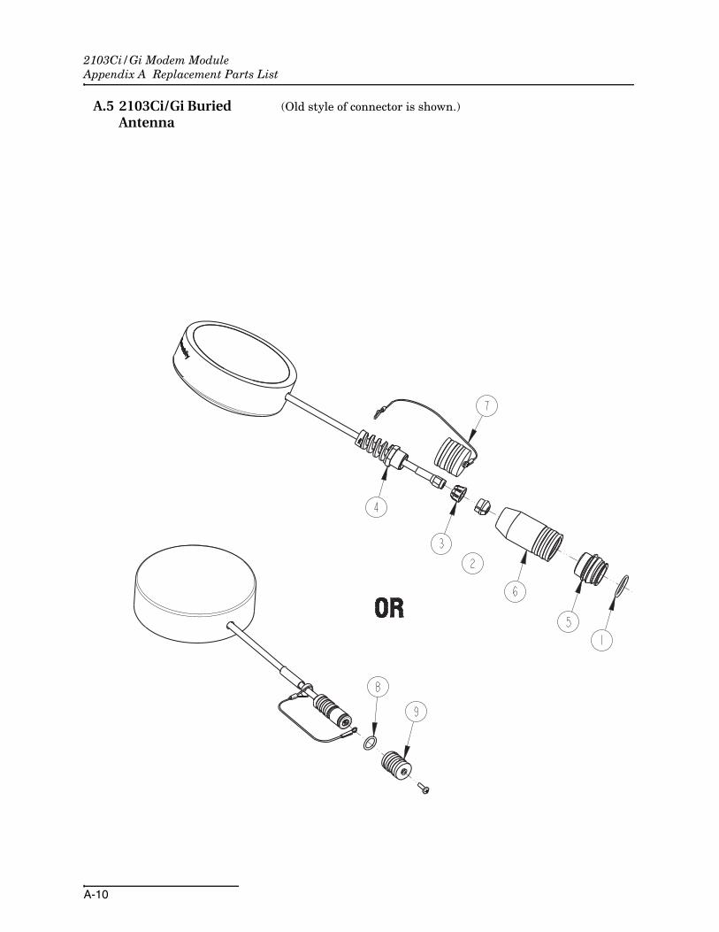
A.5 2103Ci/Gi Buried Antenna
(Old style of connector is shown.)

2103Ci/Gi Modem ModuleAppendix A Replacement Parts List
A-11

2103Ci/Gi Modem ModuleAppendix A Replacement Parts List
A-12
A.6 2191 Battery Module

2103Ci/Gi Modem ModuleAppendix A Replacement Parts List
A-13

2103Ci/Gi Modem ModuleAppendix A Replacement Parts List
A-14

B-1
2103Ci/Gi Modem Module
Appendix B Accessories
B.1 How to Order Accessories can be purchased by contacting Teledyne Isco’s Cus-tomer Service Department.
Teledyne IscoCustomer Service Dept.P.O. Box 82531Lincoln, NE 68501 USA
Phone: (800) 228-4373(402) 464-0231
FAX: (402) 465-3022
E-mail: [email protected]
B.2 General Accessories 2103Ci/Gi Instruction manual . . . . . . . . . . . . . . . . . . 69-2003-637
Alkaline Lantern Battery . . . . . . . . . . . . . . . . . . . . . . 340-2006-02
Rechargeable 6V Lead-acid Lantern Battery. . . . . . . 60-2004-041
Charging Adapter for 6V Lead-acidLantern Battery . . . . . . . . . . . . . . . . . . . . . . . . . . . . . . 60-2004-040
Flowlink and Flowlink Pro Software . . . . . . . . . . . . .(call factory)
Isco Open Channel FlowMeasurement Handbook . . . . . . . . . . . . . . . . . . . . . . . 60-3003-041
Magnetic Mount Antenna for 2103Ci . . . . . . . . . . . . . 60-2004-550
Magnetic Mount Antenna for 2103Gi . . . . . . . . . . . . . 60-2004-551
Buried-In-Street Antenna . . . . . . . . . . . . . . . . . . . . . . 60-2004-564
Manhole Lid Antenna . . . . . . . . . . . . . . . . . . . . . . . . . 60-5314-820
2103Ci/Gi Maintenance Kit. . . . . . . . . . . . . . . . . . . . . 60-2009-004

2103Ci/Gi Modem ModuleAppendix B Accessories
B-2
C-1
2103Ci/Gi Modem Modules
Appendix C Material Safety Data Sheets
C.1 Overview This appendix to the manual provides Material Safety DataSheets for the desiccant used by the 2103Ci/Gi Modem Modules.
Teledyne Isco cannot guarantee the accuracy of the data. Specificquestions regarding the use and handling of the products shouldbe directed to the manufacturer listed on the MSDS.

2103Ci/Gi Modem ModulesAppendix C Material Safety Data Sheets
C-2
MATERIAL SAFETY DATA SHEET
Effective Date March 8, 2005 MSDS Number M163
Section 1 � Product and Company Information
Product Name: Silica gel, indicating, yellow Product Use: Desiccant, absorbent Grades: Silica gel, indicating Synonyms: Amorphous silica gel, SiO2, silicon dioxide (amorphous) Company; Multisorb Technologies, Inc. Street Address: 325 Harlem Road City, State, Zip, Country: Buffalo, NY 14224-1893 USA Telephone Number: (716) 824 8900 [USA] Monday - Friday (8:00 - 5:00 EDT) Fax Number: (716) 824 4091 [USA] Website / E-Mail : multisorb.com
Section 2 � Composition / Information on Ingredients
Component Name CAS Number % by Weight Synthetic amorphous silica gel (SiO2) 112926-00-8 100 Phenolphthalein 77-09-08 100 ppm While this material is not classified, this MSDS contains valuable information critical to the safe handling and proper use of this product. This MSDS should be retained and available for employees and other users of this product.
Section 3 � Hazard Identification Emergency Overview: A yellow bead or granular material that poses little or no immediate hazard.
This material is not combustible. Potential Health Effects: Eyes: Dust and or product may cause eye discomfort and irritation seen as tearing and reddening. Skin: The product dust may cause drying of the skin. Silica gel may get hot enough to burn skin
when it adsorbs moisture rapidly. Use an excess of water to cool the silica gel. Ingestion: Material is not toxic and will pass through the body normally. Inhalation: Slight irritation is possible but none is expected. Medical Effects Generally Aggravated by Exposure: Respiratory ailments. Chronic Effects/Carcinogenity: May cause eye, skin and mucous membrane irritation and drying.

2103Ci/Gi Modem ModulesAppendix C Material Safety Data Sheets
C-3
Section 4 � First Aid Measures Eyes: Rinse the eyes well with water while lifting the eye lids. If irritation persists, consult a
physician. Skin: Wash affected area with soap and water. Ingestion: Ingestion is unlikely, this material will pass through the body normally. Inhalation: Remove the affected person to fresh air and get medical attention if necessary. Notes to Physician: Not applicable
Section 5 � Fire Fighting Measures Flammable Properties: Not flammable
Flash Point: Not applicable Method: Not applicable Flammable Limits: Not flammable
Lower Flammability Limit: Not applicable
Upper Flammability Limit: Not applicable
Autoignition Temperature: Not applicable Hazardous Combustion Products: Not applicable Extinguishing Media: Use extinguishing media that is appropriate for the surrounding fire. Silica gel is
not combustible. Fire Fighting Instructions: Not combustible Unusual Fire and Explosion Hazards: None
Section 6 � Accidental Release Measures Spill: Sweep or vacuum up and place the spilled material in a waste disposal container. Avoid raising dust.
Wash with soap and water after handling.
Section 7 � Handling and Storage Handling: Avoid raising dust and minimize the contact between worker and the material. Practice
good hygienic work practices. Storage: Store in a cool, dry location. Keep in sealed containers away from moisture. The silica gel
will readily adsorb moisture.

2103Ci/Gi Modem ModulesAppendix C Material Safety Data Sheets
C-4
Section 8 � Exposure Controls/Personal Protection Engineering Controls: Use exhaust ventilation to keep the airborne concentrations below the exposure
limits. Respiratory Protection: Use NIOSH approved respirator when the air quality levels exceed the TLV's. Skin Protection: Light gloves will protect against abrasion and drying of the skin. Eye Protection: Safety glasses.
Component Name Exposure Limits OSHA
PEL ACGIH
TLV Other
Recommended Limits
Silica gel
TWA 20 mppcf (80 mg / m3 % SiO2)
TWA 10 mg / m3
NIOSH REL TWA 6 mg / m3
IDLH 3000 mg / m3 Phenolphthalein Not Applicable Not Applicable Not Applicable
Section 9 � Physical and Chemical Properties Appearance: Yellow beads or granules Vapor Density: Not applicable Odor: None Boiling Point: 4046 F (2230 C) Physical State: Solid bead Melting Point: 3110 F (1710 C) PH: Not applicable Solubility: Insoluble in water Vapor Pressure: Not applicable Specific Gravity: 2.1
Section 10 � Stability and Reactivity Stability: Stable Conditions to avoid: Moisture and high humidity environments. Incompatibility: Water, fluorine, oxygen difluoride, chlorine trifluoride Hazardous Decomposition Products: None Hazardous Polymerization: Will not occur

2103Ci/Gi Modem ModulesAppendix C Material Safety Data Sheets
C-5
Section 11 � Toxicological Information
This product and its components are not listed on the NTP or OSHA Carcinogen lists. Animal Toxicology Tests for DOT Hazard classification ( Tests Conducted on finely ground silica gel)
1 - hour LC50 (rat) > 2 mg / l 48 - hour oral LD50 (rat) est. > 31,600 mg / kg 48 - hour dermal LD50 (rabbit) est. > 2,000 mg / kg Considered an ocular irritant Human Toxicology Silica gel is a synthetic amorphous silica not to be confused with crystalline silica. Epidemiological studies indicate low potential for adverse health effects. In the activated form, silica gel acts as a desiccant and can cause a drying irritation of the mucous membranes and skin in cases of severe exposure. Multisorb Technologies Inc. knows of no medical conditions that are abnormally aggravated by exposure to silica gel. The primary route of entry is inhalation of dust.
Section 12 � Ecological Information Not known to have any adverse effect on the aquatic environment. Silica gel is insoluble and non-toxic.
Section 13 � Disposal Information Disposal Information If this product as supplied becomes a waste, it does not meet the criteria of a hazardous waste as defined under the Resource Conservation and Recovery Act (RCRA) 40 CFR 261. Materials of a hazardous nature that contact the product during normal use may be retained on the product. The user of the product must identify the hazards associated with the retained material in order to assess the waste disposal options. Dispose according to federal, state and local regulations.
Section 14 � Transportation Information U.S. Department of Transportation Shipping Name: Not classified as a hazardous material. Not regulated.
Section 15 � Regulatory Information (Not meant to be all inclusive - selected regulations represented) TSCA Listed: Yes DSL/NDSL (Canadian) Listed: Yes OSHA: TWA 20 mppcf (80 mg / m3 % SiO2) for Silica gel NIOSH: REL TWA 6 mg / m3 IDLH 3,000 mg / m3 for silica gel Animal tests conducted in 1976 - 1978. 18 month exposure at 15 mg / m3 showed silica
deposition in respiratory macrophages and lymph nodes, minimum lung impairment, no silicosis. ACGIH: TLV - 10 mg / m3 for Silica gel DOT: Not classified as a hazardous material.

2103Ci/Gi Modem ModulesAppendix C Material Safety Data Sheets
C-6

Index-1
2103Ci/Gi Modem Modules
Index
Numerics2103Ci IP address, 3-2
Aaccessories, B-1alarms, 2-17antenna options
2103Ci, 3-22105Gi, 4-4
Bbattery module
batteries, 2-6components, 1-4
CCDMA modem module, 3-1components
2191 battery module, 1-4bottom view, 1-3identification, 1-2top view, 1-2
connector2103 pinout, 1-7
connectors, 2-5analog modem communication, 1-7
contact information, 2-1, A-1, B-1technical service, 1-9
Ddesiccant, 6-1dimensional drawings, 1-7
Ffilter, 6-3Flowlink
adding a module, 2-10connection, 2-9initial connection, 2-9modem screen, 2-13power conservation, 2-15pushed data, 2-19text messaging, 2-17
GGSM modem module, 4-1
Iinstallation, 2-3
batteries, 2-6connectors, 2-5latches, 2-3
IP connection, 2-14
Llatches, 2-3
stacking modules, 2-7
Mmaintenance, 6-1Modbus
registers, 5-5Modbus output, 5-1modem connection
serial over IP, 2-14modem module
2103Ci, 3-12103Gi, 4-1pushed data, 2-19text messaging, 2-17
modem setup screen, 2-13MSDS, C-1
Oo-rings, 6-3
Pparts, A-1, B-1power, 2-2power conservation, 2-15pushed data, 2-19
Rreplacement parts, A-1
Ssafety information, 1-9, C-1service, 6-3SIM card, 4-1specifications, 1-6stacking, 2-7

2103Ci/Gi Modem ModulesIndex
Index-2
TTCP connection, 2-14technical specifications, 1-6text messaging, 2-17
Compliance Statements
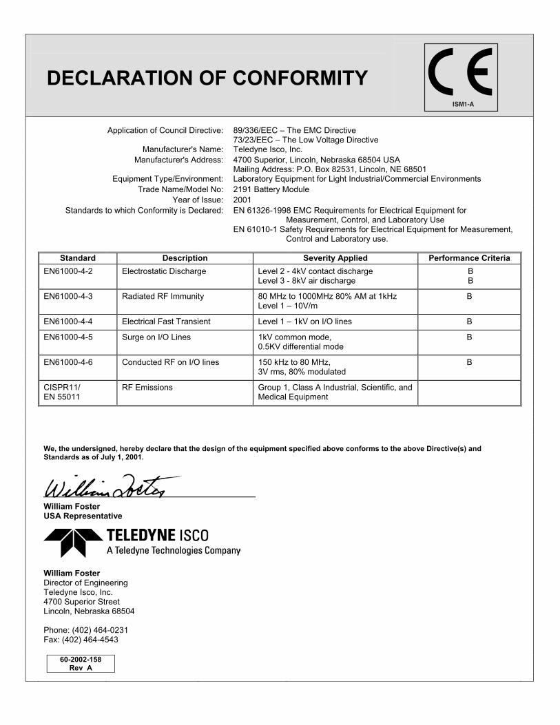
DECLARATION OF CONFORMITY
Application of Council Directive: 89/336/EEC � The EMC Directive 73/23/EEC � The Low Voltage Directive
Manufacturer's Name: Teledyne Isco, Inc. Manufacturer's Address:
4700 Superior, Lincoln, Nebraska 68504 USA Mailing Address: P.O. Box 82531, Lincoln, NE 68501
Equipment Type/Environment: Laboratory Equipment for Light Industrial/Commercial Environments Trade Name/Model No: 2191 Battery Module Year of Issue: 2001 Standards to which Conformity is Declared: EN 61326-1998 EMC Requirements for Electrical Equipment for
Measurement, Control, and Laboratory Use EN 61010-1 Safety Requirements for Electrical Equipment for Measurement,
Control and Laboratory use.
Standard Description Severity Applied Performance Criteria EN61000-4-2 Electrostatic Discharge Level 2 - 4kV contact discharge
Level 3 - 8kV air discharge B B
EN61000-4-3 Radiated RF Immunity 80 MHz to 1000MHz 80% AM at 1kHz Level 1 � 10V/m
B
EN61000-4-4 Electrical Fast Transient Level 1 � 1kV on I/O lines B
EN61000-4-5 Surge on I/O Lines 1kV common mode, 0.5KV differential mode
B
EN61000-4-6 Conducted RF on I/O lines 150 kHz to 80 MHz, 3V rms, 80% modulated
B
CISPR11/ EN 55011
RF Emissions Group 1, Class A Industrial, Scientific, and Medical Equipment
We, the undersigned, hereby declare that the design of the equipment specified above conforms to the above Directive(s) and
Standards as of July 1, 2001.
William Foster USA Representative
William Foster Director of Engineering Teledyne Isco, Inc. 4700 Superior Street Lincoln, Nebraska 68504 Phone: (402) 464-0231 Fax: (402) 464-4543
60-2002-158 Rev A


CE Dec
larat
ion o
f Con
form
ity
DECLARATION OF CONFORMITY
Application of Council Directives*: 2004/108/EC – The EMC Directive 2012/19/EC– The WEEE Directive 1999/5/EC-R&TTE Directive*
Manufacturer's Name: Teledyne Isco
Manufacturer's Address:
4700 Superior, Lincoln, Nebraska 68504 USA Mailing Address: P.O. Box 82531, Lincoln, NE 68501
Equipment Type/Environment: Laboratory Equipment for Light Industrial/Commercial Environments
Trade Name/Model No: 2103Gi 3G
Year of Issue: 2015
Standards to which Conformity is Declared: EN 61326-1:2006 EMC Requirements for Electrical Equipment for Measurement, Control, and Laboratory Use
Standard Description Severity Applied Performance Criteria
EN 61000-4-2:2008 Electrostatic Discharge Level 2 - 4kV contact discharge Level 3 - 8kV air discharge
A
EN 61000-4-3:2006 /A1:200 /A2:2010
Radiated RF Immunity 10V/m, 80 MHz to 1GHz 80% AM at 1kHz 3V/m, 1.4GHz to 12GHz 80% AM at 1kHz 1V/m, 2 GHz to 2.7GHz 80% AM at 1kHz
A A A
EN 61000-4-4:2012 Electrical Fast Transient (EFT) on Mains and I/O
Level 2 – 1kV on AC lines A
EN 61000-4-6:2013 Conducted RF on Mains and I/O lines
150 kHz to 80 MHz, 3V rms, 80% modulated
A
EN 55011:2009/A1:2010
RF Emissions Radiated, below 1 GHz and Conducted, AC Mains
Group 1, Class A Industrial, Scientific, and Medical Equipment
PASS
*Novatel Declaration of Conformity for Model CNN0402 most accompany this Declaration of Conformity
We, the undersigned, hereby declare that the design of the equipment specified above conforms to the above Directive(s) and Standards as of June 3, 2015. USA Representative
Vikas V. Padhye Ph. D. Executive Vice President Teledyne Isco 4700 Superior Street Lincoln, Nebraska 68504 Phone: (402) 464-0231 Fax: (402) 464-0318
60-2002-674 Rev B


Warranty
Teledyne Isco One Year Limited Factory Service Warranty* This warranty exclusively covers Teledyne Isco
instruments, providing a one-year limited warranty
covering parts and labor.
Any instrument that fails during the warranty period due to
faulty parts or workmanship will be repaired at the factory
at no charge to the customer. Teledyne Isco’s exclusive
liability is limited to repair or replacement of defective
instruments. Teledyne Isco is not liable for consequential
damages.
Teledyne Isco will pay surface transportation charges both
ways within the 48 contiguous United States if the
instrument proves to be defective within 30 days of
shipment. Throughout the remainder of the warranty period,
the customer will pay to return the instrument to Teledyne
Isco, and Teledyne Isco will pay surface transportation to
return the repaired instrument to the customer. Teledyne
Isco will not pay air freight or customer’s packing and
crating charges. This warranty does not cover loss, damage,
or defects resulting from transportation between the
customer’s facility and the repair facility.
The warranty for any instrument is the one in effect on date
of shipment. The warranty period begins on the shipping
date, unless Teledyne Isco agrees in writing to a different
date.
Excluded from this warranty are normal wear; expendable
items such as charts, ribbon, lamps, tubing, and glassware;
fittings and wetted parts of valves; and damage due to
corrosion, misuse, accident, or lack of proper maintenance.
This warranty does not cover products not sold under the
Teledyne Isco trademark or for which any other warranty is
specifically stated.
No item may be returned for warranty service without a
return authorization number issued by Teledyne Isco.
This warranty is expressly in lieu of all other warranties
and obligations and Teledyne Isco specifically disclaims
any warranty of merchantability or fitness for a
particular purpose.
The warrantor is Teledyne Isco, 4700 Superior, Lincoln, NE
68504, U.S.A.
* This warranty applies to the USA and countries where Teledyne Isco does not have an authorized dealer.
Customers in countries outside the USA, where Teledyne Isco has an authorized dealer, should contact their
Teledyne Isco dealer for warranty service.
Before returning any instrument for repair, please call, fax, or e-mail the Teledyne Isco Service Department for instructions. Many problems can often be diagnosed and corrected over the phone, or by e-mail, without returning the instrument to the factory. Instruments needing factory repair should be packed carefully, and shipped to the attention of the service department. Small, non-fragile items can be sent by insured parcel post. PLEASE BE SURE TO ENCLOSE A NOTE EXPLAINING THE PROBLEM.
Shipping Address: Teledyne Isco - Attention Repair Service 4700 Superior Street Lincoln, NE 68504 USA
Mailing Address: Teledyne Isco PO Box 82531 Lincoln, NE 68501 USA
Phone: Repair service: (800) 775-2965 (lab instruments) (866) 298-6174 (samplers & flow meters)
Sales & General Information: (800) 228-4373 (USA & Canada) Fax: (402) 465-3001 Email: [email protected]
February 28, 2012 P/N 60-1002-040 Rev G

