21-level three phase cascaded h-bridge multi- level ... · fig.8 output of reference wave and...
TRANSCRIPT
21-LEVEL THREE PHASE CASCADED H-BRIDGE MULTI-LEVEL INVERTER WITH DIFFERENT MULTI-CARRIER LEVEL SHIFT PWM TECHNIQUES AND THEIR THD ANALYSIS Velishala Ramu1, Dr. P. Satish kumar2 and Dr. G.N.Sreenivas3 I. INTRODUCTION Multilevel inverters are becoming more popular as they have tremendous advantages such as low harmonic distortion, improved power quality, reduced voltage stress across the switches, less electromagnetic interference and reduction in the filter size. The three basic topologies of multilevel inverter are the diode clamped, capacitor clamped and Cascaded H-bridge (CHB) multilevel inverter [1].Among these, a survey on CHB [2] has been done and concluded that it has become an attractive topology due to its modularity and simplicity to control.
Pulse width modulation (PWM) techniques play vital role in order to get the desired output in multilevel inverters,. Several modulation techniques have been proposed and introduced in the literature such as: selective harmonic elimination PWM (SHE-PWM), space vector PWM, sinusoidal PWM (SPWM), third harmonic injected PWM (THPWM), 60° modulated sinusoidal PWM (SDPWM) and trapezoidal PWM (TRPWM)
(SVPWM) and multi-carrier PWM (MCPWM). The main challenge associated with the SHE-PWM and SVPWM techniques is, complexity in calculations in multilevel inverter above 5-levels. Different PWM techniques having their own advantages and disadvantages. The MCPWM technique is the most widely used and well accepted because it is the simplest technique to generate multilevel pulses to control individual power switches for any output level inverters by comparing reference signal with triangular signals. The broad classification of multicarrier PWM is based on types of carrier signals and modulating signals. There are five well known carrier signals and are classified as level shifted or vertical shifted signals and phase shifted or Horizontal shifted signal namely; phase disposition (PD), phase opposition and disposition (POD), alternate phase opposition disposition (APOD) and phase shifted (PS) PWM can be used to implement any type of inverters. Recently, in number of literature, authors have proposed the method to mitigate the CHB power balancing problem using level shifted PWM techniques only. SPWM is the commonly used reference signal due to its simplicity to generate it. THPWM, SDPWM and TRPWM reference
1 Assistant Professor, Dept of EEE, UCE, KU Kothagudem, Telangana State, INDIA 2 Assistant Professor, Dept of Elecrical Engineering, UCE, OU Hyderabad, Telangana State, INDIA 3 Professor&HOD of EEE, JNTUH Hyderabad, Telangana State, INDIA
International Journal of Latest Trends in Engineering and Technology Vol.(8)Issue(3), pp.005-013
DOI: http://dx.doi.org/10.21172/1.83.002 e-ISSN:2278-621X
Abstract- Nowadays, the industries demanding morepower with low harmonics for the high power applications. Thus Multilevel Inverter concept has been introduced. The concept of the Multilevel Inverters becoming more popular for the high power applications due to less harmonics and high power ratings. The importance of the multilevel converters has been increased since the last decade. Several topologies have been implemented, amongst these topologies, the Cascaded H-bridge Multilevel Inverter is proposed. Cascaded MLI are ideal for connecting renewable energy sources with an AC grid. Even though the number of modulation techniques are available for controlling the multilevel inverter but, MULTI-CARRIER LEVEL-SHIFT PULSE WIDTH MODULATION TECHNIQUES are frequently used due to its simplicity and easy implementation. In this paper simplified simulation modelling of various multi-carrier level-shift PWM techniques (such as PID, PO, & APOD) are proposed for n-level generation. The proposed modulation techniques are explained for ‘21-LEVEL THREE PHASE CASCADED H-BRIDGE (CHB)’. The simulation of the modulation techniques is set up in MATLAB/Simulink. And an analysis has been made on calculating percentage THD for different multi-carrier level-shift PWM techniques.
Key words—multilevel inverter, cascaded H-bridge, multi-carrier(MC) level shift pulse width modulation techniques,PID,PO,APOD and THD.
21-Level Three Phase Cascaded H-Bridge Multi-Level Inverter With Different Multi-Carrier Level Shift Pwm Techniques And Their Thd Analysis 6
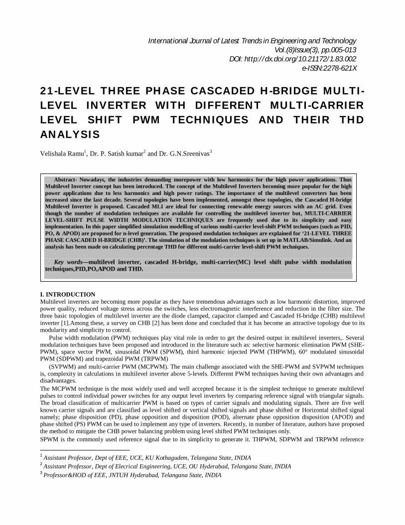
signals are used where linear modulation is required by flattening the top of these reference signals. Carrier signals and modulating signals both provides freedom in amplitude, frequency and phase. So based on combination of carrier signals and modulating signals, number of multilevel PWM output can be generated [5]. The main aim of this paper is to present a simplified way to generate simulation model for various multi-carrier level-shift PWM techniques and their performance analysis based on total harmonic distortion (THD) for 21-level three phase CHB inverter. The generation of various multi-carrier level-shift PWM techniques will be same for any multilevel inverters. The simulation results in MATLAB/SIMULINK platform. The paper is organized as follows Section II-Describes 21-level 3-phase CHB MLI & its connection diagram. Section III & IV- Theoretical method to develop various carrier signals and modulating signal. Section V- Generation of control pulses for inverter Section VI- Simulation results Section VII- Conclusion of the work is summarized. Section VIII-Future scope. II. 21-level 3-phase CHB MLI In this, each individual phase of 21-level 3-phase cascaded MLI constitutes ten cascaded H-cells. (All the ten H-cells are connected in series). The ac outputs of each of the different full-bridge inverter levels are connected in series such that the synthesized voltage waveform is the sum of the each inverter (H-cell) output.
The number of output phase voltage levels (n) in a cascade inverter is defined by n = 2h+1, where h-is the number of Separate dc sources &n-is number of output voltage levels.
Therefore, for n=2(10) +1=21 levels. Each phase produces 21-levels of output through 10 H-cells connected in series with low THD.Figure-1 shows Connection diagram of 3-phase CHB MLI (21-levels).
Fig.1 Three phase 21-level cascaded MLI

Velishala Ramu, Dr. P. Satish kumar and Dr. G.N.Sreenivas 7
III. Multi-carrier Level Shifted PWM (MCLS-PWM) In the MCLS-PWM methods all the carrier signals use triangular signals, cover the total extent range of generated converter output voltage and consist same amplitude and frequency. They are classified basically based on the placement of various carrier signals [3]. For generation of n level, n-1 carrier signals are required. For generation of 21 level, 21-1=20 carrier signals areRequired The MCLS-PWM methods are used in the controlling of inverters where power balancing is not required [3]. Here all the multi-carrier level-shifted PWM techniques are shown for R-phase. (Similarly these methods are carried out for Y & B phases respectively).
A. Phase in-phase Disposition PWM (PID-PWM) In this technique all the carrier waves are selected with same phase and magnitude. This technique compares a reference
sinusoidal wave with multiple triangular carrier waves to generate the switching pulses. For an n-Level inverter, (n-1) carrier signals are used [1].
Fig.2 Method to generate PID-PWMcarrier & reference signals for R-phase Above fig.2 shows the one phase(R-PHASE) arrangement of reference and carrier waveforms to generate switching pulses for the 21- level cascaded multi-level inverter for PID-PWM technique. Likewise PID-PWM is carried out for B, Y-phases respectively.
The reference sinusoidal waveform having peak to peak amplitude of ‘Am’ and frequency of ‘fm’ is compared with every carrier signal. The carrier signals are of the same frequency ‘fc’ and same amplitude ‘A c’. The zero amplitude is concentrated in the middle of the carrier set. If the amplitude of the reference wave is greater than the amplitude of the carrier signal, then the corresponding switch is turned ON. For a CHB multilevel inverter the amplitude modulation index MI is defined
as “The ratio of amplitude of reference wave (Am) to the amplitude of carrier wave (Ac)” & is given by “MI= (Am)/ (Ac)”
The frequency ratio (Mf) is defined as “The ratio of carrier frequency (f-car) to the reference frequency (f-mod)” & is given by
“Mf= (fc)/ (fm)” The inverter gives a zero state output when the sinusoidal signal is lesser than the upper carrier signal but more than the lower carrier wave. When the reference signal is less than first lower carrier wave, the inverter is switched to -1 (-Vdc - state) stage [1]. When the reference signal is higher than first upper carrier wave, the inverter is switched to +1 (+Vdc - state) stage. Likewise all ac outputs of each of the different cascaded H-Bridge inverters in each phase (R, Y, B) are connected in series such that the synthesized voltage waveform is the sum of the each inverter (H-cell) output. 2. Phase Opposition Disposition PWM (POD-PWM)
In case of POD-PWM technique, the carrier signals above the zero axes and below the zero axes are 180° out of phase but the carriers above the zero axes or positive carrier signals are in same phase and the carriers below the zero axes or negative carrier signals are in same phase [3].
Fig.3 Method to generate PO-PWM
21-Level Three Phase Cascaded H-Bridge Multi-Level Inverter With Different Multi-Carrier Level Shift Pwm Techniques And Their Thd Analysis 8
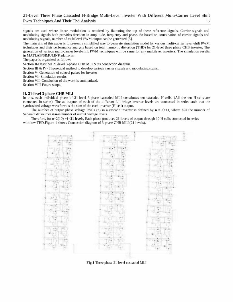
Method to generate PO-PWM carrier & reference signals for R-phase is shown in fig.3 shows the arrangement of single phase (R-PHASE) reference and carrier waveforms to generate switching pulses for the 21- level cascaded multi-level inverter for POD-PWM technique. Likewise PO-PWM is carried out for B, Y-phases respectively. 3. Alternate Phase Opposition Disposition PWM (APODPWM) In this method, the entire carrier signals are alternate 180° shifted with its neighbor is demonstrated i.e. each carrier of this method is phase shifted by 180 degrees from its adjacent carrier [3]. Below fig.4 shows the one phase (R-PHASE) arrangement of reference and carrier waveforms to generate switching pulses for the 21- level cascaded multi-level inverter for APOD-PWM technique. Likewise APOD-PWM is carried out for B, Y-phases respectively.
Fig.4 Method to generate APOD-PWM carrier &reference signals for R-phase. IV. MODULATION SIGNAL (REFERENCE SIGNAL) Sinusoidal PWM
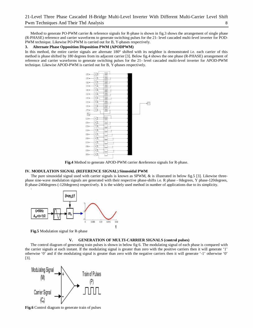
The pure sinusoidal signal used with carrier signals is known as SPWM, & is illustrated in below fig.5 [3]. Likewise three-phase sine-wave modulation signals are generated with their respective phase-shifts i.e. R phase - 0degrees, Y phase-120degrees, B phase-240degrees (-120degrees) respectively. It is the widely used method in number of applications due to its simplicity.
Fig.5 Modulation signal for R-phase
V. GENERATION OF MULTI-CARRIER SIGNALS (control pulses) The control diagram of generating train pulses is shown in below fig 6. The modulating signal of each phase is compared with
the carrier signals at each instant. If the modulating signal is greater than zero with the positive carriers then it will generate ‘1’ otherwise ‘0’ and if the modulating signal is greater than zero with the negative carriers then it will generate ‘-1’ otherwise ‘0’ [3]. Fig.6 Control diagram to generate train of pulses
Velishala Ramu, Dr. P. Satish kumar and Dr. G.N.Sreenivas 9
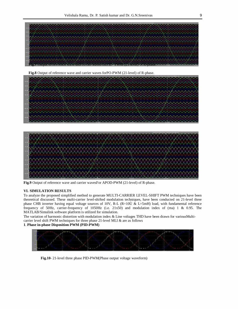
Fig.7 Output of reference wave and carrier waves forPID- PWM (21-level) of R-phase.
Fig.8 Output of reference wave and carrier waves forPO-PWM (21-level) of R-phase. Fig.9 Output of reference wave and carrier wavesFor APOD-PWM (21-level) of R-phase. VI. SIMULATION RESULTS To analyze the proposed simplified method to generate MULTI-CARRIER LEVEL-SHIFT PWM techniques have been theoretical discussed. These multi-carrier level-shifted modulation techniques, have been conducted on 21-level three phase CHB inverter having equal voltage sources of 10V, R-L (R=10Ù & L=5mH) load, with fundamental reference frequency of 50Hz, carrier-frequency of 1050Hz (i.e. 21x50) and modulation index of (ma) 1 & 0.95. The MATLAB/Simulink software platform is utilized for simulation. The variation of harmonic distortion with modulation index & Line voltages THD have been drawn for variousMulti-carrier level shift PWM techniques for three phase 21-level MLI & are as follows 1. Phase in-phase Disposition PWM (PID-PWM)
Fig.10- 21-level three phase PID-PWM(Phase output voltage waveform)
21-Level Three Phase Cascaded H-Bridge Multi-Level Inverter With Different Multi-Carrier Level Shift Pwm Techniques And Their Thd Analysis 10
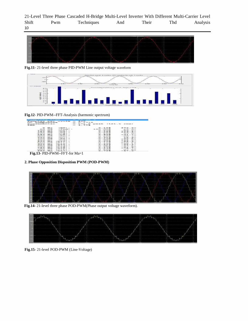
Fig.11- 21-level three phase PID-PWM Line output voltage waveform
Fig.12- PID-PWM--FFT-Analysis (harmonic spectrum)
Fig.13- PID-PWM--FFT-for Ma=1 2. Phase Opposition Disposition PWM (POD-PWM)
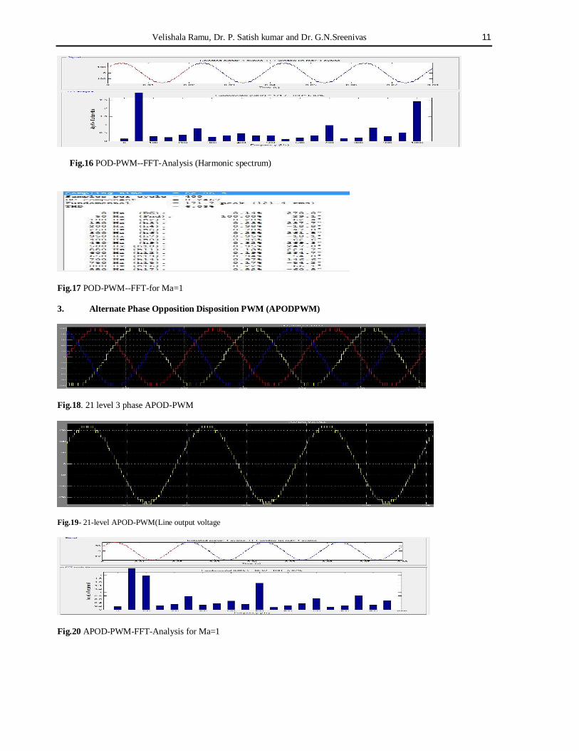
Fig.14- 21-level three phase POD-PWM(Phase output voltage waveform).
Fig.15- 21-level POD-PWM (Line-Voltage)
Velishala Ramu, Dr. P. Satish kumar and Dr. G.N.Sreenivas 11
Fig.16 POD-PWM--FFT-Analysis (Harmonic spectrum)
Fig.17 POD-PWM--FFT-for Ma=1
3. Alternate Phase Opposition Disposition PWM (APODPWM)
Fig.18. 21 level 3 phase APOD-PWM
Fig.19- 21-level APOD-PWM(Line output voltage
Fig.20 APOD-PWM-FFT-Analysis for Ma=1
21-Level Three Phase Cascaded H-Bridge Multi-Level Inverter With Different Multi-Carrier Level Shift Pwm Techniques And Their Thd Analysis 12
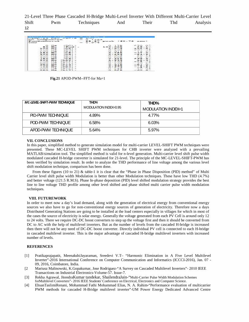
MC-LEVEL-SHIFT-PWM TECHNIQUE THD%
MODULATION INDEX=0.95 THD%
MODULATION INDEX=1 PID-PWM TECHNIQUE 4.89% 4.77%
POD-PWM TECHNIQUE 6.58% 6.03%
APOD-PWM TECHNIQUE 5.64% 5.97%
VII. CONCLUSIONS In this paper, simplified method to generate simulation model for multi-carrier LEVEL-SHIFT PWM techniques were presented. These MC-LEVEL SHIFT PWM techniques for CHB inverter were analyzed with a prevailing MATLAB/simulation tool. The simplified method is valid for n-level generation. Multi-carrier level shift pulse width modulated cascaded H-bridge converter is simulated for 21-level. The principle of the MC-LEVEL-SHIFT-PWM has been verified by simulation result. In order to analyze the THD performance of line voltage among the various level shift modulation technique, comparison has been done.
From these figures (10 to 21) & table-1 it is clear that the “Phase in Phase Disposition (PID) method” of Multi Carrier level shift pulse width Modulation is better than other Modulation techniques. These have low THD (4.7%) and better voltage (121.5 R.M.S). Phase In-phase deposition (PID) level shifted modulation strategy provides the best line to line voltage THD profile among other level shifted and phase shifted multi carrier pulse width modulation techniques.
VIII. FUTUREWORK
In order to meet now a day’s load demand, along with the generation of electrical energy from conventional energy sources we also have to go for non-conventional energy sources of generation of electricity. Therefore now a days Distributed Generating Stations are going to be installed at the load centers especially in villages for which in most of the cases the source of electricity is solar energy. Generally the voltage generated from each PV Cell is around only 12 to 24 volts. There we require DC-DC boost converters to step up the voltage first and then it should be converted from DC to AC with the help of multilevel inverters. But as the number of levels from the cascaded H-bridge is increased then there will not be any need of DC-DC boost converter. Directly individual PV cell is connected to each H-bridge in cascaded multilevel inverter. This is the major advantage of cascaded H-bridge multilevel inverters with increased number of levels.
REFERENCES
[1] Pratikaprajapatit, MeenakshiJayaraman, Sreedevi V.T– “Harmonic Elimination in A Five Level Multilevel
Inverter”-2016 International Conference on Computer Communication and Informatics (ICCCI-2016), Jan. 07 - 09, 2016, Coimbatore, India.
[2 Mariusz Malinowski, K.Gopakumar, Jose Rodriguez-“A Survey on Cascaded Multilevel Inverters”- 2010 IEEE Transactions on Industrial Electronics-Volume-57. Issue-7.
[3] Rekha Agrawal, JitendraKumar tandekar, ShailendraJain-“Multi-Carrier Pulse Width Modulation Schemes forMultilevel Converters”- 2016 IEEE Students' Conference on Electrical, Electronics and Computer Science.
[4] EhsanTaslimiRenani, Mohammad Fathi Mohammad Elias, N. A. Rahim-“Performance evaluation of multicarrier PWM methods for cascaded H-Bridge multilevel inverter”-UM Power Energy Dedicated Advanced Centre
Fig.21 APOD-PWM--FFT-for Ma=1

Velishala Ramu, Dr. P. Satish kumar and Dr. G.N.Sreenivas 13
(UMPEDAC), Level 4, Wisma R&D, UM, JalanPantai Baharu, 59990 Kuala Lumpur, Malaysia. [5] K.L.Dheeraj, M.Diwakar, M.DurgaRaj, M.Eswar, K.NagaVenkatesh-“THD Analysis of Cascaded MLI for
Various PWM Techniques”- international journal of engineering trends And technology (IJETT)-Volume-11 number 3-May 2014.