2.1 general
TRANSCRIPT

2.1 GENERAL
2.1.1 EQUIPMENT LIST 2.1.2 AUXILIARY POWER CONSUMPTION LIST 2.1.3 TECHNICAL DESCRIPTION - PLANT OVERALL
LIST TOTAL 15 PAGE
(Including Cover)
● PROJECT CODE : A50346EA ● PROJECT NAME : NUEVA VENTANAS 240MW COAL FIRED
POWER PROJECT
● DOCUMENT No. : WD000-EM440-00001 ● TITLE : EQUIPMENT LIST – MECHANICAL
● OWNER: EMPRESA ELÉCTRICA VENTANAS S.A.
Purpose □ For Review □ For Approval □ For Construction □ For Bid ■ As Built
F 2009/11/30 K.H.Choi W.S.Kim C.H.Choi As Built M.H.Han H.S.Woo B.I.Moon
3 2009/04/02 K.H.Choi W.S.Kim C.H.Choi For Information M.H.Han H.S.Woo B.I.Moon
2 2008/07/14 K.H.Choi M.S.Han C.H.Choi For Information M.H.Han H.S.Woo B.I.Moon
1 2008/04/14 E.S.Lee M.S.Han C.H.Choi For Information M.H.Han H.S.Woo B.I.Moon
0 2007/05/31 E.S.Lee M.S.Han C.H.Choi For Information M.H.Han H.S.Woo B.I.Moon
PREPA REVIEW APPR REVIEW REVIEW APPR Rev.No. DATE
HEC DESCRIPTION
POSCO E&C
Owner :
EMPRESA ELÉCTRICA VENTANAS S.A
Contractor :
Nueva Ventanas 240MW Coal Fired Power Project
Equipment List - Mechanical
Rev. F
SERVICE TOTAL OPER.
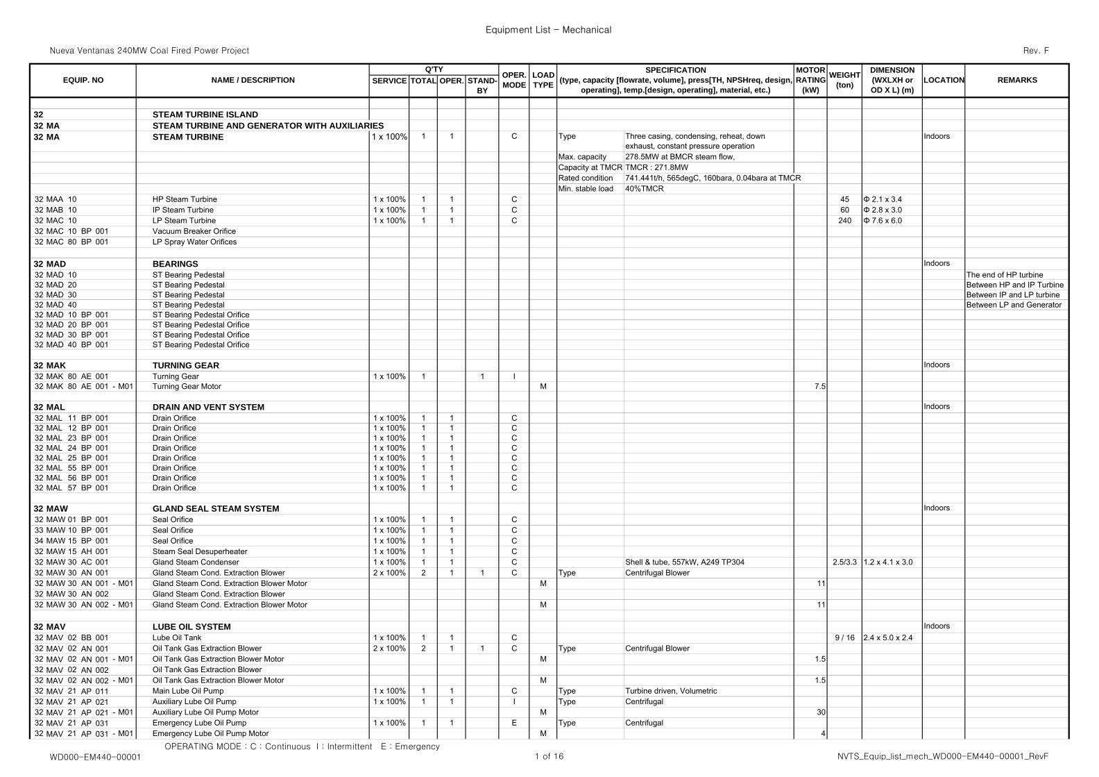
32 STEAM TURBINE ISLAND32 MA STEAM TURBINE AND GENERATOR WITH AUXILIARIES32 MA STEAM TURBINE 1 x 100% 1 1 C Type Three casing, condensing, reheat, down
exhaust, constant pressure operationIndoors
Max. capacity 278.5MW at BMCR steam flow, Capacity at TMCR TMCR : 271.8MWRated condition 741.441t/h, 565degC, 160bara, 0.04bara at TMCRMin. stable load 40%TMCR
32 MAA 10 HP Steam Turbine 1 x 100% 1 1 C 45 Φ 2.1 x 3.432 MAB 10 IP Steam Turbine 1 x 100% 1 1 C 60 Φ 2.8 x 3.032 MAC 10 LP Steam Turbine 1 x 100% 1 1 C 240 Φ 7.6 x 6.032 MAC 10 BP 001 Vacuum Breaker Orifice 32 MAC 80 BP 001 LP Spray Water Orifices
32 MAD BEARINGS Indoors32 MAD 10 ST Bearing Pedestal The end of HP turbine32 MAD 20 ST Bearing Pedestal Between HP and IP Turbine32 MAD 30 ST Bearing Pedestal Between IP and LP turbine32 MAD 40 ST Bearing Pedestal Between LP and Generator32 MAD 10 BP 001 ST Bearing Pedestal Orifice32 MAD 20 BP 001 ST Bearing Pedestal Orifice32 MAD 30 BP 001 ST Bearing Pedestal Orifice32 MAD 40 BP 001 ST Bearing Pedestal Orifice
32 MAK TURNING GEAR Indoors32 MAK 80 AE 001 Turning Gear 1 x 100% 1 1 I32 MAK 80 AE 001 - M01 Turning Gear Motor M 7.5
32 MAL DRAIN AND VENT SYSTEM Indoors32 MAL 11 BP 001 Drain Orifice 1 x 100% 1 1 C32 MAL 12 BP 001 Drain Orifice 1 x 100% 1 1 C32 MAL 23 BP 001 Drain Orifice 1 x 100% 1 1 C32 MAL 24 BP 001 Drain Orifice 1 x 100% 1 1 C32 MAL 25 BP 001 Drain Orifice 1 x 100% 1 1 C32 MAL 55 BP 001 Drain Orifice 1 x 100% 1 1 C32 MAL 56 BP 001 Drain Orifice 1 x 100% 1 1 C32 MAL 57 BP 001 Drain Orifice 1 x 100% 1 1 C
32 MAW GLAND SEAL STEAM SYSTEM Indoors32 MAW 01 BP 001 Seal Orifice 1 x 100% 1 1 C33 MAW 10 BP 001 Seal Orifice 1 x 100% 1 1 C34 MAW 15 BP 001 Seal Orifice 1 x 100% 1 1 C32 MAW 15 AH 001 Steam Seal Desuperheater 1 x 100% 1 1 C32 MAW 30 AC 001 Gland Steam Condenser 1 x 100% 1 1 C Shell & tube, 557kW, A249 TP304 2.5/3.3 1.2 x 4.1 x 3.032 MAW 30 AN 001 Gland Steam Cond. Extraction Blower 2 x 100% 2 1 1 C Type Centrifugal Blower32 MAW 30 AN 001 - M01 Gland Steam Cond. Extraction Blower Motor M 1132 MAW 30 AN 002 Gland Steam Cond. Extraction Blower32 MAW 30 AN 002 - M01 Gland Steam Cond. Extraction Blower Motor M 11
32 MAV LUBE OIL SYSTEM Indoors32 MAV 02 BB 001 Lube Oil Tank 1 x 100% 1 1 C 9 / 16 2.4 x 5.0 x 2.432 MAV 02 AN 001 Oil Tank Gas Extraction Blower 2 x 100% 2 1 1 C Type Centrifugal Blower32 MAV 02 AN 001 - M01 Oil Tank Gas Extraction Blower Motor M 1.532 MAV 02 AN 002 Oil Tank Gas Extraction Blower32 MAV 02 AN 002 - M01 Oil Tank Gas Extraction Blower Motor M 1.532 MAV 21 AP 011 Main Lube Oil Pump 1 x 100% 1 1 C Type Turbine driven, Volumetric32 MAV 21 AP 021 Auxiliary Lube Oil Pump 1 x 100% 1 1 I Type Centrifugal 32 MAV 21 AP 021 - M01 Auxiliary Lube Oil Pump Motor M 3032 MAV 21 AP 031 Emergency Lube Oil Pump 1 x 100% 1 1 E Type Centrifugal 32 MAV 21 AP 031 - M01 Emergency Lube Oil Pump Motor M 4
MOTORRATING
(kW)
OPER.MODE
LOADTYPE REMARKSWEIGHT
(ton)
DIMENSION(WXLXH orOD X L) (m)
LOCATIONSPECIFICATION
(type, capacity [flowrate, volume], press[TH, NPSHreq, design,operating], temp.[design, operating], material, etc.)
STAND-BY
EQUIP. NOQ'TY
NAME / DESCRIPTION
OPERATING MODE : C : Continuous I : Intermittent E : EmergencyWD000-EM440-00001 1 of 16 NVTS_Equip_list_mech_WD000-EM440-00001_RevF
Nueva Ventanas 240MW Coal Fired Power Project
Equipment List - Mechanical
Rev. F
SERVICE TOTAL OPER.MOTORRATING
(kW)
OPER.MODE
LOADTYPE REMARKSWEIGHT
(ton)
DIMENSION(WXLXH orOD X L) (m)
LOCATIONSPECIFICATION
(type, capacity [flowrate, volume], press[TH, NPSHreq, design,operating], temp.[design, operating], material, etc.)
STAND-BY
EQUIP. NOQ'TY
NAME / DESCRIPTION
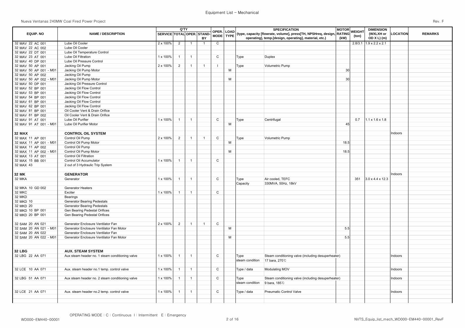
32 MAV 22 AC 001 Lube Oil Cooler 2 x 100% 2 1 1 C 2.8/3.1 1.9 x 2.2 x 2.132 MAV 22 AC 002 Lube Oil Cooler 32 MAV 22 DT 001 Lube Oil Temperature Control 32 MAV 23 AT 001 Lube Oil Filtration 1 x 100% 1 1 C Type Duplex32 MAV 40 DP 001 Lube Oil Pressure Control 32 MAV 50 AP 001 Jacking Oil Pump 2 x 100% 2 1 1 I Type Volumetric Pump32 MAV 50 AP 001 - M01 Jacking Oil Pump Motor M 3032 MAV 50 AP 002 Jacking Oil Pump 32 MAV 50 AP 002 - M01 Jacking Oil Pump Motor M 3032 MAV 50 DP 001 Jacking Oil Pressure Control 32 MAV 52 BP 001 Jacking Oil Flow Control 32 MAV 53 BP 001 Jacking Oil Flow Control 32 MAV 54 BP 001 Jacking Oil Flow Control 32 MAV 61 BP 001 Jacking Oil Flow Control 32 MAV 62 BP 001 Jacking Oil Flow Control 32 MAV 81 BP 001 Oil Cooler Vent & Drain Orifice32 MAV 81 BP 002 Oil Cooler Vent & Drain Orifice32 MAV 91 AT 001 Lube Oil Purifier 1 x 100% 1 1 C Type Centrifugal 0.7 1.1 x 1.6 x 1.832 MAV 91 AT 001 - M01 Lube Oil Purifier Motor M 45
32 MAX CONTROL OIL SYSTEM Indoors32 MAX 11 AP 001 Control Oil Pump 2 x 100% 2 1 1 C Type Volumetric Pump32 MAX 11 AP 001 - M01 Control Oil Pump Motor M 18.532 MAX 11 AP 002 Control Oil Pump 32 MAX 11 AP 002 - M01 Control Oil Pump Motor M 18.532 MAX 13 AT 001 Control Oil Filtration 32 MAX 15 BB 001 Control Oil Accumulator 1 x 100% 1 1 C32 MAX 43 2 out of 3 Hydraulic Trip System
32 MK GENERATOR Indoors32 MKA Generator 1 x 100% 1 1 C Type Air cooled, TEFC 351 3.0 x 4.4 x 12.3
Capacity 330MVA, 50Hz, 18kV32 MKA 10 GD 002 Generator Heaters32 MKC Exciter 1 x 100% 1 1 C32 MKD Bearings32 MKD 10 Generator Bearing Pedestals 32 MKD 20 Generator Bearing Pedestals 32 MKD 10 BP 001 Gen Bearing Pedestal Orifices 32 MKD 20 BP 001 Gen Bearing Pedestal Orifices
32 SAM 20 AN 021 Generator Enclosure Ventilator Fan 2 x 100% 2 1 1 C32 SAM 20 AN 021 - M01 Generator Enclosure Ventilator Fan Motor M 5.532 SAM 20 AN 022 Generator Enclosure Ventilator Fan32 SAM 20 AN 022 - M01 Generator Enclosure Ventilator Fan Motor M 5.5
32 LBG AUX. STEAM SYSTEM32 LBG 22 AA 071 Aux steam header no. 1 steam conditioning valve 1 x 100% 1 1 C Type Steam conditioning valve (including desuperheater) Indoors
steam condition 17 bara, 270℃
32 LCE 10 AA 071 Aux. steam header no.1 temp. control valve 1 x 100% 1 1 C Type / data Modulating MOV Indoors
32 LBG 51 AA 071 Aux steam header no. 2 steam conditioning valve 1 x 100% 1 1 C Type Steam conditioning valve (including desuperheater) Indoorssteam condition 9 bara, 185℃
32 LCE 21 AA 071 Aux. steam header no.2 temp. control valve 1 x 100% 1 1 C Type / data Pneumatic Control Valve Indoors
OPERATING MODE : C : Continuous I : Intermittent E : EmergencyWD000-EM440-00001 2 of 16 NVTS_Equip_list_mech_WD000-EM440-00001_RevF
Nueva Ventanas 240MW Coal Fired Power Project
Equipment List - Mechanical
Rev. F
SERVICE TOTAL OPER.MOTORRATING
(kW)
OPER.MODE
LOADTYPE REMARKSWEIGHT
(ton)
DIMENSION(WXLXH orOD X L) (m)
LOCATIONSPECIFICATION
(type, capacity [flowrate, volume], press[TH, NPSHreq, design,operating], temp.[design, operating], material, etc.)
STAND-BY
EQUIP. NOQ'TY
NAME / DESCRIPTION
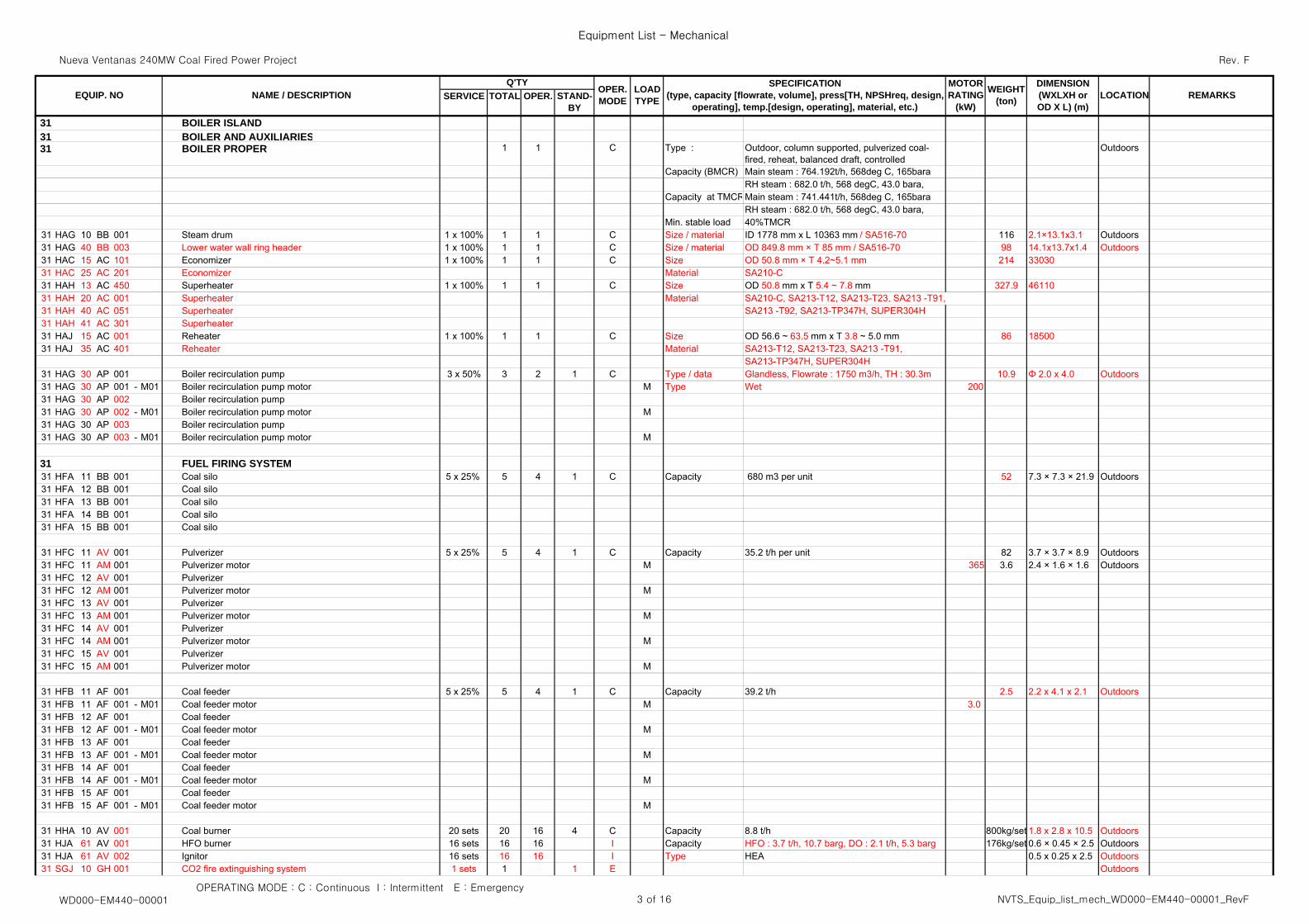
31 BOILER ISLAND31 BOILER AND AUXILIARIES31 BOILER PROPER 1 1 C Type : Outdoor, column supported, pulverized coal-
fired, reheat, balanced draft, controlledOutdoors
Capacity (BMCR) Main steam : 764.192t/h, 568deg C, 165baraRH steam : 682.0 t/h, 568 degC, 43.0 bara,
Capacity at TMCRMain steam : 741.441t/h, 568deg C, 165baraRH steam : 682.0 t/h, 568 degC, 43.0 bara,
Min. stable load 40%TMCR31 HAG 10 BB 001 Steam drum 1 x 100% 1 1 C Size / material ID 1778 mm x L 10363 mm / SA516-70 116 2.1×13.1x3.1 Outdoors31 HAG 40 BB 003 Lower water wall ring header 1 x 100% 1 1 C Size / material OD 849.8 mm × T 85 mm / SA516-70 98 14.1x13.7x1.4 Outdoors31 HAC 15 AC 101 Economizer 1 x 100% 1 1 C Size OD 50.8 mm × T 4.2~5.1 mm 214 3303031 HAC 25 AC 201 Economizer Material SA210-C31 HAH 13 AC 450 Superheater 1 x 100% 1 1 C Size OD 50.8 mm x T 5.4 ~ 7.8 mm 327.9 4611031 HAH 20 AC 001 Superheater Material SA210-C, SA213-T12, SA213-T23, SA213 -T91, 31 HAH 40 AC 051 Superheater SA213 -T92, SA213-TP347H, SUPER304H31 HAH 41 AC 301 Superheater31 HAJ 15 AC 001 Reheater 1 x 100% 1 1 C Size OD 56.6 ~ 63.5 mm x T 3.8 ~ 5.0 mm 86 1850031 HAJ 35 AC 401 Reheater Material SA213-T12, SA213-T23, SA213 -T91,
SA213-TP347H, SUPER304H31 HAG 30 AP 001 Boiler recirculation pump 3 x 50% 3 2 1 C Type / data Glandless, Flowrate : 1750 m3/h, TH : 30.3m 10.9 Φ 2.0 x 4.0 Outdoors31 HAG 30 AP 001 - M01 Boiler recirculation pump motor M Type Wet 20031 HAG 30 AP 002 Boiler recirculation pump31 HAG 30 AP 002 - M01 Boiler recirculation pump motor M31 HAG 30 AP 003 Boiler recirculation pump31 HAG 30 AP 003 - M01 Boiler recirculation pump motor M
31 FUEL FIRING SYSTEM31 HFA 11 BB 001 Coal silo 5 x 25% 5 4 1 C Capacity 680 m3 per unit 52 7.3 × 7.3 × 21.9 Outdoors31 HFA 12 BB 001 Coal silo31 HFA 13 BB 001 Coal silo31 HFA 14 BB 001 Coal silo31 HFA 15 BB 001 Coal silo
31 HFC 11 AV 001 Pulverizer 5 x 25% 5 4 1 C Capacity 35.2 t/h per unit 82 3.7 × 3.7 × 8.9 Outdoors31 HFC 11 AM 001 Pulverizer motor M 365 3.6 2.4 × 1.6 × 1.6 Outdoors31 HFC 12 AV 001 Pulverizer31 HFC 12 AM 001 Pulverizer motor M31 HFC 13 AV 001 Pulverizer31 HFC 13 AM 001 Pulverizer motor M31 HFC 14 AV 001 Pulverizer31 HFC 14 AM 001 Pulverizer motor M31 HFC 15 AV 001 Pulverizer31 HFC 15 AM 001 Pulverizer motor M
31 HFB 11 AF 001 Coal feeder 5 x 25% 5 4 1 C Capacity 39.2 t/h 2.5 2.2 x 4.1 x 2.1 Outdoors31 HFB 11 AF 001 - M01 Coal feeder motor M 3.031 HFB 12 AF 001 Coal feeder31 HFB 12 AF 001 - M01 Coal feeder motor M31 HFB 13 AF 001 Coal feeder31 HFB 13 AF 001 - M01 Coal feeder motor M31 HFB 14 AF 001 Coal feeder31 HFB 14 AF 001 - M01 Coal feeder motor M31 HFB 15 AF 001 Coal feeder31 HFB 15 AF 001 - M01 Coal feeder motor M
31 HHA 10 AV 001 Coal burner 20 sets 20 16 4 C Capacity 8.8 t/h 800kg/set 1.8 x 2.8 x 10.5 Outdoors31 HJA 61 AV 001 HFO burner 16 sets 16 16 I Capacity HFO : 3.7 t/h, 10.7 barg, DO : 2.1 t/h, 5.3 barg 176kg/set 0.6 × 0.45 × 2.5 Outdoors31 HJA 61 AV 002 Ignitor 16 sets 16 16 I Type HEA 0.5 x 0.25 x 2.5 Outdoors31 SGJ 10 GH 001 CO2 fire extinguishing system 1 sets 1 1 E Outdoors
OPERATING MODE : C : Continuous I : Intermittent E : EmergencyWD000-EM440-00001 3 of 16 NVTS_Equip_list_mech_WD000-EM440-00001_RevF
Nueva Ventanas 240MW Coal Fired Power Project
Equipment List - Mechanical
Rev. F
SERVICE TOTAL OPER.MOTORRATING
(kW)
OPER.MODE
LOADTYPE REMARKSWEIGHT
(ton)
DIMENSION(WXLXH orOD X L) (m)
LOCATIONSPECIFICATION
(type, capacity [flowrate, volume], press[TH, NPSHreq, design,operating], temp.[design, operating], material, etc.)
STAND-BY
EQUIP. NOQ'TY
NAME / DESCRIPTION
OPERATING MODE : C : Continuous I : Intermittent E : EmergencyWD000-EM440-00001 4 of 16 NVTS_Equip_list_mech_WD000-EM440-00001_RevF
Nueva Ventanas 240MW Coal Fired Power Project
Equipment List - Mechanical
Rev. F
SERVICE TOTAL OPER.MOTORRATING
(kW)
OPER.MODE
LOADTYPE REMARKSWEIGHT
(ton)
DIMENSION(WXLXH orOD X L) (m)
LOCATIONSPECIFICATION
(type, capacity [flowrate, volume], press[TH, NPSHreq, design,operating], temp.[design, operating], material, etc.)
STAND-BY
EQUIP. NOQ'TY
NAME / DESCRIPTION
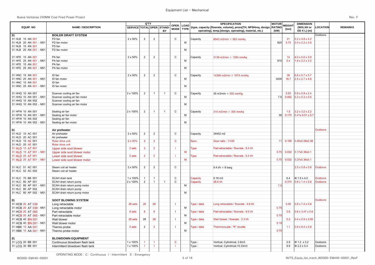
31 BOILER DRAFT SYSTEM Outdoors31 HLB 15 AN 001 FD fan 2 x 50% 2 2 C Capacity 6543 m3/min × 563 mmAq 21 5.2 x 4.8 x 4.231 HLB 25 AN 001 - M01 FD fan motor M 820 5.75 2.0 x 2.2 x 3.031 HLB 15 AN 001 FD fan 31 HLB 25 AN 001 - M01 FD fan motor M
31 HFE 15 AN 001 PA fan 2 x 50% 2 2 C Capacity 3139 m3/min × 1293 mmAq 14 4.0 x 5.0 x 3.031 HFE 25 AN 001 - M01 PA fan motor M 910 5.4 1.8 x 2.2 x 3.2 31 HFE 15 AN 001 PA fan31 HFE 25 AN 001 - M01 PA fan motor M
31 HNC 15 AN 001 ID fan 2 x 50% 2 2 C Capacity 14399 m3/min × 1073 mmAq 39 6.6 x 5.7 x 5.731 HNC 25 AN 001 - M01 ID fan motor M 3430 16.7 2.5 x 2.7 x 4.831 HNC 15 AN 001 ID fan31 HNC 25 AN 001 - M01 ID fan motor M
31 HHQ 10 AN 001 Scanner cooling air fan 2 x 100% 2 1 1 C Capacity 35 m3/min × 550 mmHg 0.62 0.9 x 0.9 x 2.431 HHQ 10 AN 001 - M01 Scanner cooling air fan motor M 7.5 0.052 0.3 x 0.3 x 0.531 HHQ 10 AN 002 Scanner cooling air fan31 HHQ 10 AN 002 - M01 Scanner cooling air fan motor M
31 HFW 10 AN 001 Sealing air fan 2 x 100% 2 1 1 C Capacity 315 m3/min × 305 mmAq 1.5 3.2 x 3.2 x 2.231 HFW 10 AN 001 - M01 Sealing air fan motor M 30 0.175 0.41x 0.51 x 0.731 HFW 10 AN 002 Sealing air fan31 HFW 10 AN 002 - M01 Sealing air fan motor M
31 Air preheater Outdoors31 HLD 10 AC 001 Air preheater 2 x 50% 2 2 C Capacity 34452 m231 HLD 20 AC 001 Air preheater31 HLD 10 AE 001 Rotor drive unit 2 x 50% 2 2 C Spec. Gear ratio : 1/120 11 0.109 0.45x0.58x0.3831 HLD 20 AE 001 Rotor drive unit31 HLD 15 AT 001 Upper side soot blower 2 sets 2 2 I Type Part retractable / flowrate : 5.4 t/h31 HLD 15 AT 001 - M01 Upper side soot blower motor M 0.75 0.032 0.17x0.36x0.131 HLD 25 AT 001 Lower side soot blower 2 sets 2 2 I Type Part retractable / flowrate : 5.4 t/h31 HLD 25 AT 001 - M01 Lower side soot blower motor M 0.75 0.032 0.27x0.36x0.1
31 HLC 51 AC 001 Steam coil air heater 2 x 50% 2 2 C 9.4 t/h × 8 barg 2.5 x 5.8 x 0.6 Outdoors31 HLC 52 AC 002 Steam coil air heater
31 HLC 70 BB 001 SCAH drain tank 1 x 100% 1 1 C Capacity 6.18 m3 6.4 Φ 1.5 x 4.0 Outdoors31 HLC 80 AP 001 SCAH drain return pump 2 x 100% 2 1 1 C Capacity 26.6 t/h 0.374 0.6 x 1.4 x 0.8 Outdoors31 HLC 80 AP 001 - M01 SCAH drain return pump motor M 7.531 HLC 80 AP 002 SCAH drain return pump31 HLC 80 AP 002 - M01 SCAH drain return pump motor M
31 SOOT BLOWING SYSTEM Outdoors31 HCB 20 AT 039 Long retractable 26 sets 26 26 I Type / data Long retractable / flowrate : 4.6 t/h 0.95 0.6 x 7.4 x 0.631 HCB 20 AT 039 - M01 Long retractable motor M 0.7531 HCB 20 AT 065 Part retractable 8 sets 8 8 I Type / data Part retractable / flowrate : 8.0 t/h 0.6 0.6 x 3.47 x 0.631 HCB 20 AT 065 - M01 Part retractable motor M 0.7531 HCB 40 BN 001 Wall blower 28 sets 28 28 I Type / data Wall blower / flowrate : 3.3 t/h 0.2 0.4 x 0.9 x 0.5531 HCB 40 BN 001 - M01 Wall blower motor M 0.1831 HBK 10 AA 041 Thermo probe 2 sets 2 2 I Type / data Thermocouple : "K" double 1.1 0.6 x 8.2 x 0.831 HBK 10 AA 041 - M01 Thermo probe motor M 0.75
31 BLOWDOWN EQUIPMENT31 LCQ 20 BB 001 Continuous blowdown flash tank 1 x 100% 1 1 C Type : Vertical, Cylindrical, 2.6m3 2.9 Φ 1.2 x 3.2 Outdoors31 LCQ 30 BB 001 Intermittent blowdown flash tank 1 x 100% 1 1 I Type : Vertical, Cylindrical,15.33m3 9.9 Φ 2.2 x 5.4 Outdoors
OPERATING MODE : C : Continuous I : Intermittent E : EmergencyWD000-EM440-00001 5 of 16 NVTS_Equip_list_mech_WD000-EM440-00001_RevF
Nueva Ventanas 240MW Coal Fired Power Project
Equipment List - Mechanical
Rev. F
SERVICE TOTAL OPER.MOTORRATING
(kW)
OPER.MODE
LOADTYPE REMARKSWEIGHT
(ton)
DIMENSION(WXLXH orOD X L) (m)
LOCATIONSPECIFICATION
(type, capacity [flowrate, volume], press[TH, NPSHreq, design,operating], temp.[design, operating], material, etc.)
STAND-BY
EQUIP. NOQ'TY
NAME / DESCRIPTION
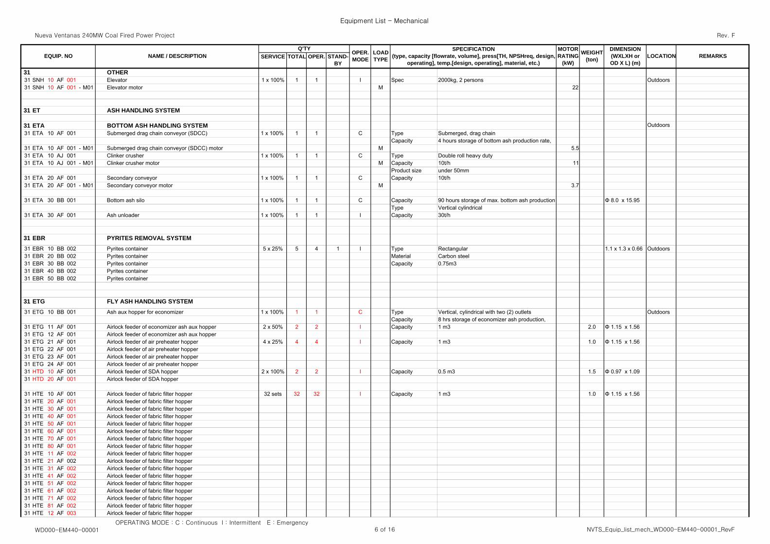
31 OTHER31 SNH 10 AF 001 Elevator 1 x 100% 1 1 I Spec 2000kg, 2 persons Outdoors31 SNH 10 AF 001 - M01 Elevator motor M 22
31 ET ASH HANDLING SYSTEM
31 ETA BOTTOM ASH HANDLING SYSTEM Outdoors31 ETA 10 AF 001 Submerged drag chain conveyor (SDCC) 1 x 100% 1 1 C Type Submerged, drag chain
Capacity 4 hours storage of bottom ash production rate,31 ETA 10 AF 001 - M01 Submerged drag chain conveyor (SDCC) motor M 5.531 ETA 10 AJ 001 Clinker crusher 1 x 100% 1 1 C Type Double roll heavy duty31 ETA 10 AJ 001 - M01 Clinker crusher motor M Capacity 10t/h 11
Product size under 50mm31 ETA 20 AF 001 Secondary conveyor 1 x 100% 1 1 C Capacity 10t/h31 ETA 20 AF 001 - M01 Secondary conveyor motor M 3.7
31 ETA 30 BB 001 Bottom ash silo 1 x 100% 1 1 C Capacity 90 hours storage of max. bottom ash production Φ 8.0 x 15.95 Type Vertical cylindrical
31 ETA 30 AF 001 Ash unloader 1 x 100% 1 1 I Capacity 30t/h
31 EBR PYRITES REMOVAL SYSTEM31 EBR 10 BB 002 Pyrites container 5 x 25% 5 4 1 I Type Rectangular 1.1 x 1.3 x 0.66 Outdoors31 EBR 20 BB 002 Pyrites container Material Carbon steel31 EBR 30 BB 002 Pyrites container Capacity 0.75m331 EBR 40 BB 002 Pyrites container31 EBR 50 BB 002 Pyrites container
31 ETG FLY ASH HANDLING SYSTEM31 ETG 10 BB 001 Ash aux hopper for economizer 1 x 100% 1 1 C Type Vertical, cylindrical with two (2) outlets Outdoors
Capacity 8 hrs storage of economizer ash production,31 ETG 11 AF 001 Airlock feeder of economizer ash aux hopper 2 x 50% 2 2 I Capacity 1 m3 2.0 Φ 1.15 x 1.56 31 ETG 12 AF 001 Airlock feeder of economizer ash aux hopper31 ETG 21 AF 001 Airlock feeder of air preheater hopper 4 x 25% 4 4 I Capacity 1 m3 1.0 Φ 1.15 x 1.56 31 ETG 22 AF 001 Airlock feeder of air preheater hopper31 ETG 23 AF 001 Airlock feeder of air preheater hopper31 ETG 24 AF 001 Airlock feeder of air preheater hopper31 HTD 10 AF 001 Airlock feeder of SDA hopper 2 x 100% 2 2 I Capacity 0.5 m3 1.5 Φ 0.97 x 1.09 31 HTD 20 AF 001 Airlock feeder of SDA hopper
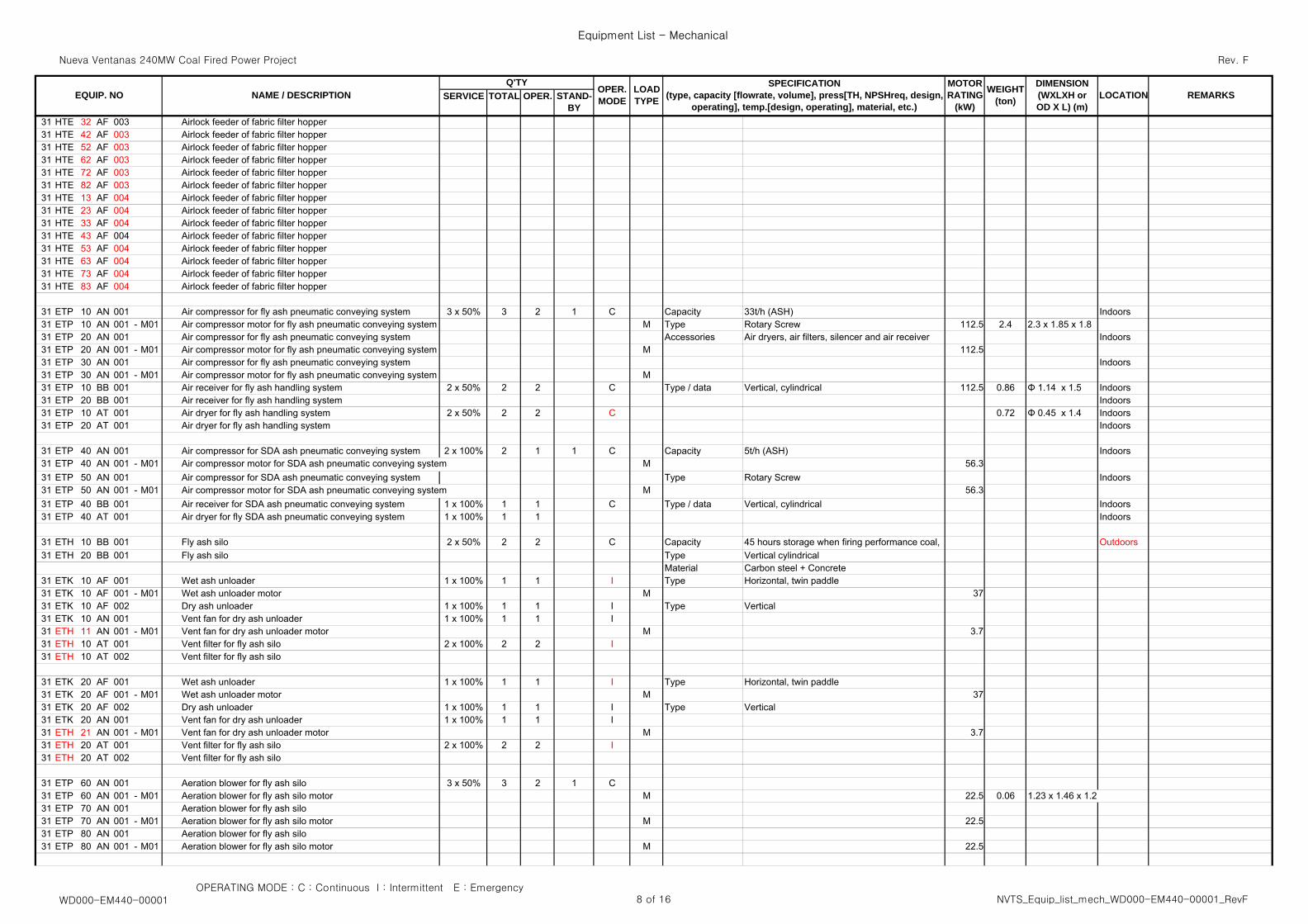
31 HTE 10 AF 001 Airlock feeder of fabric filter hopper 32 sets 32 32 I Capacity 1 m3 1.0 Φ 1.15 x 1.56 31 HTE 20 AF 001 Airlock feeder of fabric filter hopper31 HTE 30 AF 001 Airlock feeder of fabric filter hopper31 HTE 40 AF 001 Airlock feeder of fabric filter hopper31 HTE 50 AF 001 Airlock feeder of fabric filter hopper31 HTE 60 AF 001 Airlock feeder of fabric filter hopper31 HTE 70 AF 001 Airlock feeder of fabric filter hopper31 HTE 80 AF 001 Airlock feeder of fabric filter hopper31 HTE 11 AF 002 Airlock feeder of fabric filter hopper31 HTE 21 AF 002 Airlock feeder of fabric filter hopper31 HTE 31 AF 002 Airlock feeder of fabric filter hopper31 HTE 41 AF 002 Airlock feeder of fabric filter hopper31 HTE 51 AF 002 Airlock feeder of fabric filter hopper31 HTE 61 AF 002 Airlock feeder of fabric filter hopper31 HTE 71 AF 002 Airlock feeder of fabric filter hopper31 HTE 81 AF 002 Airlock feeder of fabric filter hopper31 HTE 12 AF 003 Airlock feeder of fabric filter hopper
OPERATING MODE : C : Continuous I : Intermittent E : EmergencyWD000-EM440-00001 6 of 16 NVTS_Equip_list_mech_WD000-EM440-00001_RevF
Nueva Ventanas 240MW Coal Fired Power Project
Equipment List - Mechanical
Rev. F
SERVICE TOTAL OPER.MOTORRATING
(kW)
OPER.MODE
LOADTYPE REMARKSWEIGHT
(ton)
DIMENSION(WXLXH orOD X L) (m)
LOCATIONSPECIFICATION
(type, capacity [flowrate, volume], press[TH, NPSHreq, design,operating], temp.[design, operating], material, etc.)
STAND-BY
EQUIP. NOQ'TY
NAME / DESCRIPTION
31 HTE 22 AF 003 Airlock feeder of fabric filter hopper
OPERATING MODE : C : Continuous I : Intermittent E : EmergencyWD000-EM440-00001 7 of 16 NVTS_Equip_list_mech_WD000-EM440-00001_RevF
Nueva Ventanas 240MW Coal Fired Power Project
Equipment List - Mechanical
Rev. F
SERVICE TOTAL OPER.MOTORRATING
(kW)
OPER.MODE
LOADTYPE REMARKSWEIGHT
(ton)
DIMENSION(WXLXH orOD X L) (m)
LOCATIONSPECIFICATION
(type, capacity [flowrate, volume], press[TH, NPSHreq, design,operating], temp.[design, operating], material, etc.)
STAND-BY
EQUIP. NOQ'TY
NAME / DESCRIPTION
31 HTE 32 AF 003 Airlock feeder of fabric filter hopper31 HTE 42 AF 003 Airlock feeder of fabric filter hopper31 HTE 52 AF 003 Airlock feeder of fabric filter hopper31 HTE 62 AF 003 Airlock feeder of fabric filter hopper31 HTE 72 AF 003 Airlock feeder of fabric filter hopper31 HTE 82 AF 003 Airlock feeder of fabric filter hopper31 HTE 13 AF 004 Airlock feeder of fabric filter hopper31 HTE 23 AF 004 Airlock feeder of fabric filter hopper31 HTE 33 AF 004 Airlock feeder of fabric filter hopper31 HTE 43 AF 004 Airlock feeder of fabric filter hopper31 HTE 53 AF 004 Airlock feeder of fabric filter hopper31 HTE 63 AF 004 Airlock feeder of fabric filter hopper31 HTE 73 AF 004 Airlock feeder of fabric filter hopper31 HTE 83 AF 004 Airlock feeder of fabric filter hopper
31 ETP 10 AN 001 Air compressor for fly ash pneumatic conveying system 3 x 50% 3 2 1 C Capacity 33t/h (ASH) Indoors31 ETP 10 AN 001 - M01 Air compressor motor for fly ash pneumatic conveying system M Type Rotary Screw 112.5 2.4 2.3 x 1.85 x 1.831 ETP 20 AN 001 Air compressor for fly ash pneumatic conveying system Accessories Air dryers, air filters, silencer and air receiver Indoors31 ETP 20 AN 001 - M01 Air compressor motor for fly ash pneumatic conveying system M 112.531 ETP 30 AN 001 Air compressor for fly ash pneumatic conveying system Indoors31 ETP 30 AN 001 - M01 Air compressor motor for fly ash pneumatic conveying system M31 ETP 10 BB 001 Air receiver for fly ash handling system 2 x 50% 2 2 C Type / data Vertical, cylindrical 112.5 0.86 Φ 1.14 x 1.5 Indoors31 ETP 20 BB 001 Air receiver for fly ash handling system Indoors31 ETP 10 AT 001 Air dryer for fly ash handling system 2 x 50% 2 2 C 0.72 Φ 0.45 x 1.4 Indoors31 ETP 20 AT 001 Air dryer for fly ash handling system Indoors
31 ETP 40 AN 001 Air compressor for SDA ash pneumatic conveying system 2 x 100% 2 1 1 C Capacity 5t/h (ASH) Indoors31 ETP 40 AN 001 - M01 Air compressor motor for SDA ash pneumatic conveying system M 56.331 ETP 50 AN 001 Air compressor for SDA ash pneumatic conveying system Type Rotary Screw Indoors31 ETP 50 AN 001 - M01 Air compressor motor for SDA ash pneumatic conveying system M 56.331 ETP 40 BB 001 Air receiver for SDA ash pneumatic conveying system 1 x 100% 1 1 C Type / data Vertical, cylindrical Indoors31 ETP 40 AT 001 Air dryer for fly SDA ash pneumatic conveying system 1 x 100% 1 1 Indoors
31 ETH 10 BB 001 Fly ash silo 2 x 50% 2 2 C Capacity 45 hours storage when firing performance coal, Outdoors31 ETH 20 BB 001 Fly ash silo Type Vertical cylindrical
Material Carbon steel + Concrete31 ETK 10 AF 001 Wet ash unloader 1 x 100% 1 1 I Type Horizontal, twin paddle31 ETK 10 AF 001 - M01 Wet ash unloader motor M 3731 ETK 10 AF 002 Dry ash unloader 1 x 100% 1 1 I Type Vertical31 ETK 10 AN 001 Vent fan for dry ash unloader 1 x 100% 1 1 I31 ETH 11 AN 001 - M01 Vent fan for dry ash unloader motor M 3.731 ETH 10 AT 001 Vent filter for fly ash silo 2 x 100% 2 2 I31 ETH 10 AT 002 Vent filter for fly ash silo
31 ETK 20 AF 001 Wet ash unloader 1 x 100% 1 1 I Type Horizontal, twin paddle31 ETK 20 AF 001 - M01 Wet ash unloader motor M 3731 ETK 20 AF 002 Dry ash unloader 1 x 100% 1 1 I Type Vertical31 ETK 20 AN 001 Vent fan for dry ash unloader 1 x 100% 1 1 I31 ETH 21 AN 001 - M01 Vent fan for dry ash unloader motor M 3.731 ETH 20 AT 001 Vent filter for fly ash silo 2 x 100% 2 2 I31 ETH 20 AT 002 Vent filter for fly ash silo
31 ETP 60 AN 001 Aeration blower for fly ash silo 3 x 50% 3 2 1 C31 ETP 60 AN 001 - M01 Aeration blower for fly ash silo motor M 22.5 0.06 1.23 x 1.46 x 1.2 31 ETP 70 AN 001 Aeration blower for fly ash silo31 ETP 70 AN 001 - M01 Aeration blower for fly ash silo motor M 22.531 ETP 80 AN 001 Aeration blower for fly ash silo31 ETP 80 AN 001 - M01 Aeration blower for fly ash silo motor M 22.5
OPERATING MODE : C : Continuous I : Intermittent E : EmergencyWD000-EM440-00001 8 of 16 NVTS_Equip_list_mech_WD000-EM440-00001_RevF
Nueva Ventanas 240MW Coal Fired Power Project
Equipment List - Mechanical
Rev. F
SERVICE TOTAL OPER.MOTORRATING
(kW)
OPER.MODE
LOADTYPE REMARKSWEIGHT
(ton)
DIMENSION(WXLXH orOD X L) (m)
LOCATIONSPECIFICATION
(type, capacity [flowrate, volume], press[TH, NPSHreq, design,operating], temp.[design, operating], material, etc.)
STAND-BY
EQUIP. NOQ'TY
NAME / DESCRIPTION
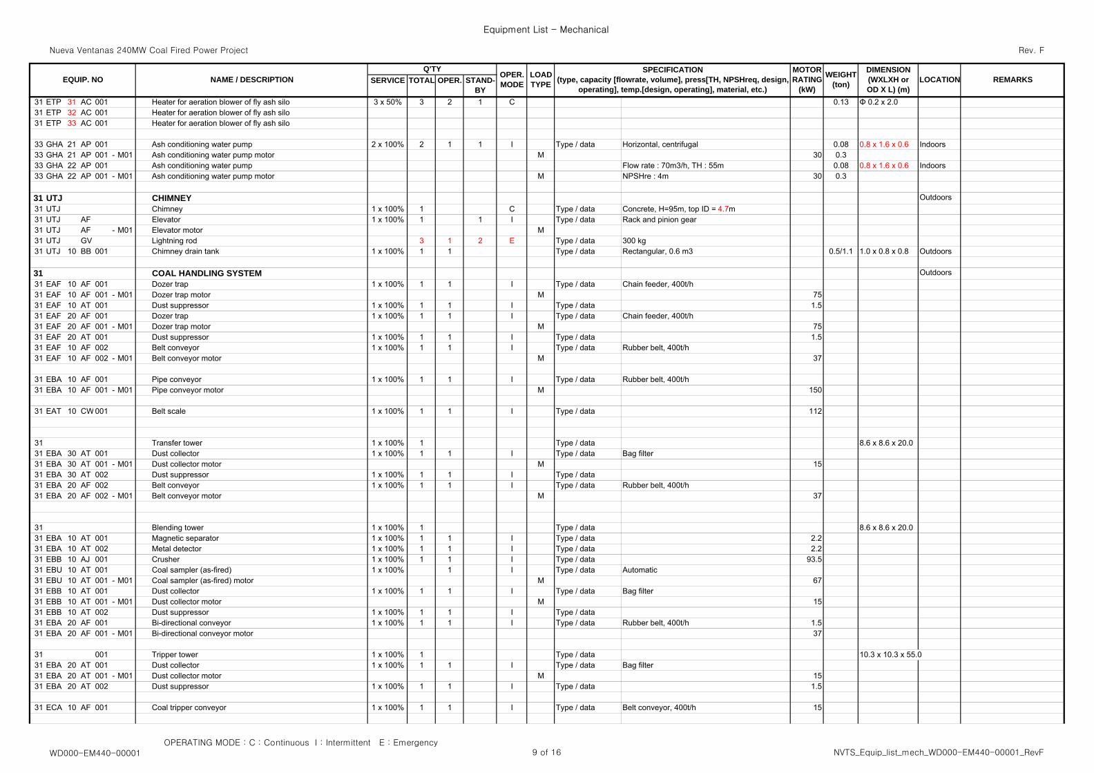
31 ETP 31 AC 001 Heater for aeration blower of fly ash silo 3 x 50% 3 2 1 C 0.13 Φ 0.2 x 2.031 ETP 32 AC 001 Heater for aeration blower of fly ash silo31 ETP 33 AC 001 Heater for aeration blower of fly ash silo
33 GHA 21 AP 001 Ash conditioning water pump 2 x 100% 2 1 1 I Type / data Horizontal, centrifugal 0.08 0.8 x 1.6 x 0.6 Indoors33 GHA 21 AP 001 - M01 Ash conditioning water pump motor M 30 0.333 GHA 22 AP 001 Ash conditioning water pump Flow rate : 70m3/h, TH : 55m 0.08 0.8 x 1.6 x 0.6 Indoors33 GHA 22 AP 001 - M01 Ash conditioning water pump motor M NPSHre : 4m 30 0.3
31 UTJ CHIMNEY Outdoors31 UTJ Chimney 1 x 100% 1 C Type / data Concrete, H=95m, top ID = 4.7m31 UTJ AF Elevator 1 x 100% 1 1 I Type / data Rack and pinion gear31 UTJ AF - M01 Elevator motor M31 UTJ GV Lightning rod 3 1 2 E Type / data 300 kg31 UTJ 10 BB 001 Chimney drain tank 1 x 100% 1 1 Type / data Rectangular, 0.6 m3 0.5/1.1 1.0 x 0.8 x 0.8 Outdoors
31 COAL HANDLING SYSTEM Outdoors31 EAF 10 AF 001 Dozer trap 1 x 100% 1 1 I Type / data Chain feeder, 400t/h31 EAF 10 AF 001 - M01 Dozer trap motor M 7531 EAF 10 AT 001 Dust suppressor 1 x 100% 1 1 I Type / data 1.531 EAF 20 AF 001 Dozer trap 1 x 100% 1 1 I Type / data Chain feeder, 400t/h31 EAF 20 AF 001 - M01 Dozer trap motor M 7531 EAF 20 AT 001 Dust suppressor 1 x 100% 1 1 I Type / data 1.531 EAF 10 AF 002 Belt conveyor 1 x 100% 1 1 I Type / data Rubber belt, 400t/h31 EAF 10 AF 002 - M01 Belt conveyor motor M 37
31 EBA 10 AF 001 Pipe conveyor 1 x 100% 1 1 I Type / data Rubber belt, 400t/h31 EBA 10 AF 001 - M01 Pipe conveyor motor M 150
31 EAT 10 CW 001 Belt scale 1 x 100% 1 1 I Type / data 112
31 Transfer tower 1 x 100% 1 Type / data 8.6 x 8.6 x 20.031 EBA 30 AT 001 Dust collector 1 x 100% 1 1 I Type / data Bag filter31 EBA 30 AT 001 - M01 Dust collector motor M 1531 EBA 30 AT 002 Dust suppressor 1 x 100% 1 1 I Type / data31 EBA 20 AF 002 Belt conveyor 1 x 100% 1 1 I Type / data Rubber belt, 400t/h31 EBA 20 AF 002 - M01 Belt conveyor motor M 37
31 Blending tower 1 x 100% 1 Type / data 8.6 x 8.6 x 20.031 EBA 10 AT 001 Magnetic separator 1 x 100% 1 1 I Type / data 2.231 EBA 10 AT 002 Metal detector 1 x 100% 1 1 I Type / data 2.231 EBB 10 AJ 001 Crusher 1 x 100% 1 1 I Type / data 93.531 EBU 10 AT 001 Coal sampler (as-fired) 1 x 100% 1 I Type / data Automatic31 EBU 10 AT 001 - M01 Coal sampler (as-fired) motor M 6731 EBB 10 AT 001 Dust collector 1 x 100% 1 1 I Type / data Bag filter31 EBB 10 AT 001 - M01 Dust collector motor M 1531 EBB 10 AT 002 Dust suppressor 1 x 100% 1 1 I Type / data31 EBA 20 AF 001 Bi-directional conveyor 1 x 100% 1 1 I Type / data Rubber belt, 400t/h 1.531 EBA 20 AF 001 - M01 Bi-directional conveyor motor 37
31 001 Tripper tower 1 x 100% 1 Type / data 10.3 x 10.3 x 55.031 EBA 20 AT 001 Dust collector 1 x 100% 1 1 I Type / data Bag filter31 EBA 20 AT 001 - M01 Dust collector motor M 1531 EBA 20 AT 002 Dust suppressor 1 x 100% 1 1 I Type / data 1.5
31 ECA 10 AF 001 Coal tripper conveyor 1 x 100% 1 1 I Type / data Belt conveyor, 400t/h 15
OPERATING MODE : C : Continuous I : Intermittent E : EmergencyWD000-EM440-00001 9 of 16 NVTS_Equip_list_mech_WD000-EM440-00001_RevF
Nueva Ventanas 240MW Coal Fired Power Project
Equipment List - Mechanical
Rev. F
SERVICE TOTAL OPER.MOTORRATING
(kW)
OPER.MODE
LOADTYPE REMARKSWEIGHT
(ton)
DIMENSION(WXLXH orOD X L) (m)
LOCATIONSPECIFICATION
(type, capacity [flowrate, volume], press[TH, NPSHreq, design,operating], temp.[design, operating], material, etc.)
STAND-BY
EQUIP. NOQ'TY
NAME / DESCRIPTION
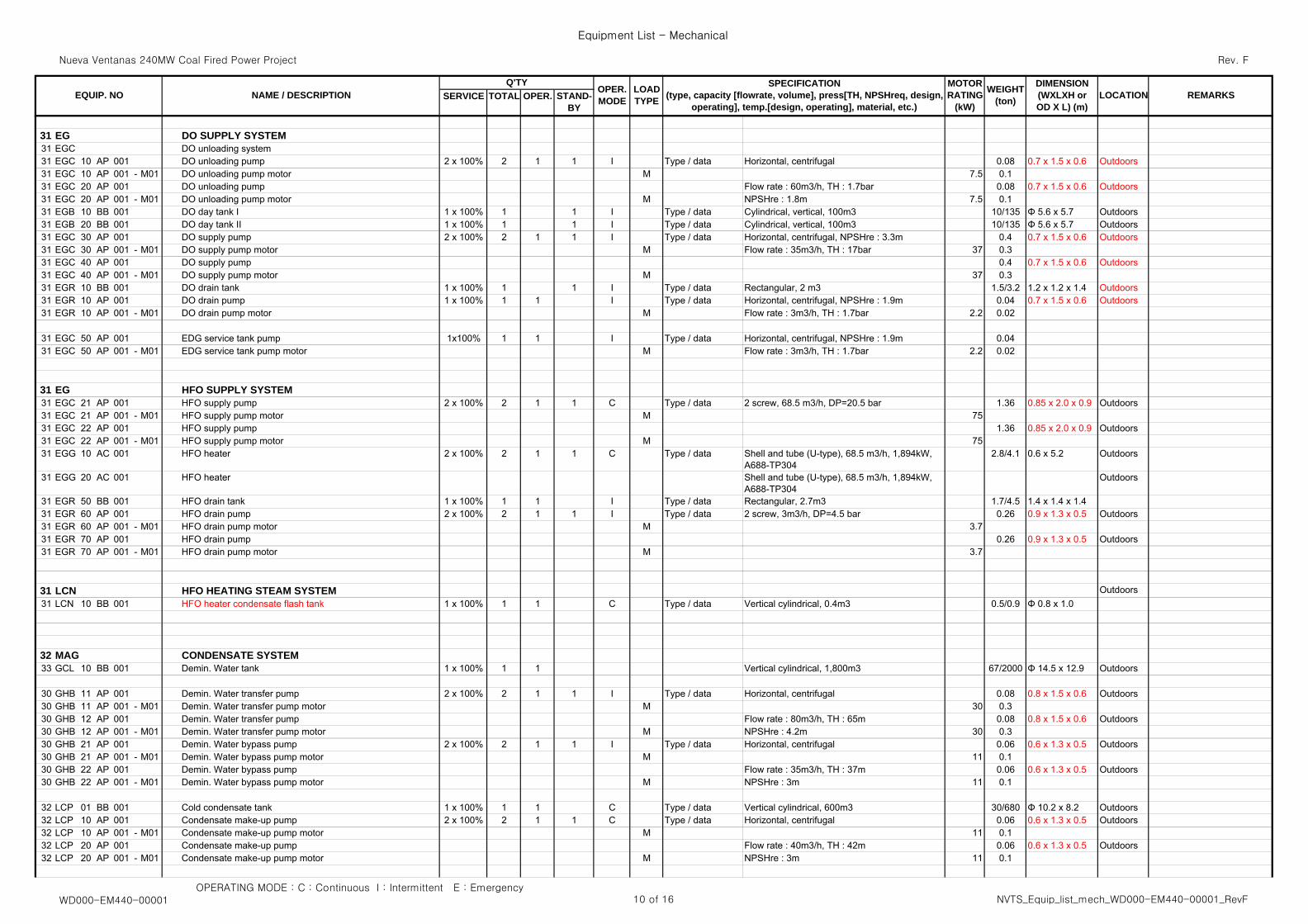
31 EG DO SUPPLY SYSTEM31 EGC DO unloading system31 EGC 10 AP 001 DO unloading pump 2 x 100% 2 1 1 I Type / data Horizontal, centrifugal 0.08 0.7 x 1.5 x 0.6 Outdoors31 EGC 10 AP 001 - M01 DO unloading pump motor M 7.5 0.131 EGC 20 AP 001 DO unloading pump Flow rate : 60m3/h, TH : 1.7bar 0.08 0.7 x 1.5 x 0.6 Outdoors31 EGC 20 AP 001 - M01 DO unloading pump motor M NPSHre : 1.8m 7.5 0.131 EGB 10 BB 001 DO day tank I 1 x 100% 1 1 I Type / data Cylindrical, vertical, 100m3 10/135 Φ 5.6 x 5.7 Outdoors31 EGB 20 BB 001 DO day tank II 1 x 100% 1 1 I Type / data Cylindrical, vertical, 100m3 10/135 Φ 5.6 x 5.7 Outdoors31 EGC 30 AP 001 DO supply pump 2 x 100% 2 1 1 I Type / data Horizontal, centrifugal, NPSHre : 3.3m 0.4 0.7 x 1.5 x 0.6 Outdoors31 EGC 30 AP 001 - M01 DO supply pump motor M Flow rate : 35m3/h, TH : 17bar 37 0.331 EGC 40 AP 001 DO supply pump 0.4 0.7 x 1.5 x 0.6 Outdoors31 EGC 40 AP 001 - M01 DO supply pump motor M 37 0.331 EGR 10 BB 001 DO drain tank 1 x 100% 1 1 I Type / data Rectangular, 2 m3 1.5/3.2 1.2 x 1.2 x 1.4 Outdoors31 EGR 10 AP 001 DO drain pump 1 x 100% 1 1 I Type / data Horizontal, centrifugal, NPSHre : 1.9m 0.04 0.7 x 1.5 x 0.6 Outdoors31 EGR 10 AP 001 - M01 DO drain pump motor M Flow rate : 3m3/h, TH : 1.7bar 2.2 0.02
31 EGC 50 AP 001 EDG service tank pump 1x100% 1 1 I Type / data Horizontal, centrifugal, NPSHre : 1.9m 0.0431 EGC 50 AP 001 - M01 EDG service tank pump motor M Flow rate : 3m3/h, TH : 1.7bar 2.2 0.02
31 EG HFO SUPPLY SYSTEM31 EGC 21 AP 001 HFO supply pump 2 x 100% 2 1 1 C Type / data 2 screw, 68.5 m3/h, DP=20.5 bar 1.36 0.85 x 2.0 x 0.9 Outdoors31 EGC 21 AP 001 - M01 HFO supply pump motor M 7531 EGC 22 AP 001 HFO supply pump 1.36 0.85 x 2.0 x 0.9 Outdoors31 EGC 22 AP 001 - M01 HFO supply pump motor M 7531 EGG 10 AC 001 HFO heater 2 x 100% 2 1 1 C Type / data Shell and tube (U-type), 68.5 m3/h, 1,894kW,
A688-TP3042.8/4.1 0.6 x 5.2 Outdoors
31 EGG 20 AC 001 HFO heater Shell and tube (U-type), 68.5 m3/h, 1,894kW,A688-TP304
Outdoors
31 EGR 50 BB 001 HFO drain tank 1 x 100% 1 1 I Type / data Rectangular, 2.7m3 1.7/4.5 1.4 x 1.4 x 1.431 EGR 60 AP 001 HFO drain pump 2 x 100% 2 1 1 I Type / data 2 screw, 3m3/h, DP=4.5 bar 0.26 0.9 x 1.3 x 0.5 Outdoors31 EGR 60 AP 001 - M01 HFO drain pump motor M 3.731 EGR 70 AP 001 HFO drain pump 0.26 0.9 x 1.3 x 0.5 Outdoors31 EGR 70 AP 001 - M01 HFO drain pump motor M 3.7
31 LCN HFO HEATING STEAM SYSTEM Outdoors31 LCN 10 BB 001 HFO heater condensate flash tank 1 x 100% 1 1 C Type / data Vertical cylindrical, 0.4m3 0.5/0.9 Φ 0.8 x 1.0
32 MAG CONDENSATE SYSTEM33 GCL 10 BB 001 Demin. Water tank 1 x 100% 1 1 Vertical cylindrical, 1,800m3 67/2000 Φ 14.5 x 12.9 Outdoors
30 GHB 11 AP 001 Demin. Water transfer pump 2 x 100% 2 1 1 I Type / data Horizontal, centrifugal 0.08 0.8 x 1.5 x 0.6 Outdoors30 GHB 11 AP 001 - M01 Demin. Water transfer pump motor M 30 0.330 GHB 12 AP 001 Demin. Water transfer pump Flow rate : 80m3/h, TH : 65m 0.08 0.8 x 1.5 x 0.6 Outdoors30 GHB 12 AP 001 - M01 Demin. Water transfer pump motor M NPSHre : 4.2m 30 0.330 GHB 21 AP 001 Demin. Water bypass pump 2 x 100% 2 1 1 I Type / data Horizontal, centrifugal 0.06 0.6 x 1.3 x 0.5 Outdoors30 GHB 21 AP 001 - M01 Demin. Water bypass pump motor M 11 0.130 GHB 22 AP 001 Demin. Water bypass pump Flow rate : 35m3/h, TH : 37m 0.06 0.6 x 1.3 x 0.5 Outdoors30 GHB 22 AP 001 - M01 Demin. Water bypass pump motor M NPSHre : 3m 11 0.1
32 LCP 01 BB 001 Cold condensate tank 1 x 100% 1 1 C Type / data Vertical cylindrical, 600m3 30/680 Φ 10.2 x 8.2 Outdoors32 LCP 10 AP 001 Condensate make-up pump 2 x 100% 2 1 1 C Type / data Horizontal, centrifugal 0.06 0.6 x 1.3 x 0.5 Outdoors32 LCP 10 AP 001 - M01 Condensate make-up pump motor M 11 0.132 LCP 20 AP 001 Condensate make-up pump Flow rate : 40m3/h, TH : 42m 0.06 0.6 x 1.3 x 0.5 Outdoors32 LCP 20 AP 001 - M01 Condensate make-up pump motor M NPSHre : 3m 11 0.1
OPERATING MODE : C : Continuous I : Intermittent E : EmergencyWD000-EM440-00001 10 of 16 NVTS_Equip_list_mech_WD000-EM440-00001_RevF
Nueva Ventanas 240MW Coal Fired Power Project
Equipment List - Mechanical
Rev. F
SERVICE TOTAL OPER.MOTORRATING
(kW)
OPER.MODE
LOADTYPE REMARKSWEIGHT
(ton)
DIMENSION(WXLXH orOD X L) (m)
LOCATIONSPECIFICATION
(type, capacity [flowrate, volume], press[TH, NPSHreq, design,operating], temp.[design, operating], material, etc.)
STAND-BY
EQUIP. NOQ'TY
NAME / DESCRIPTION
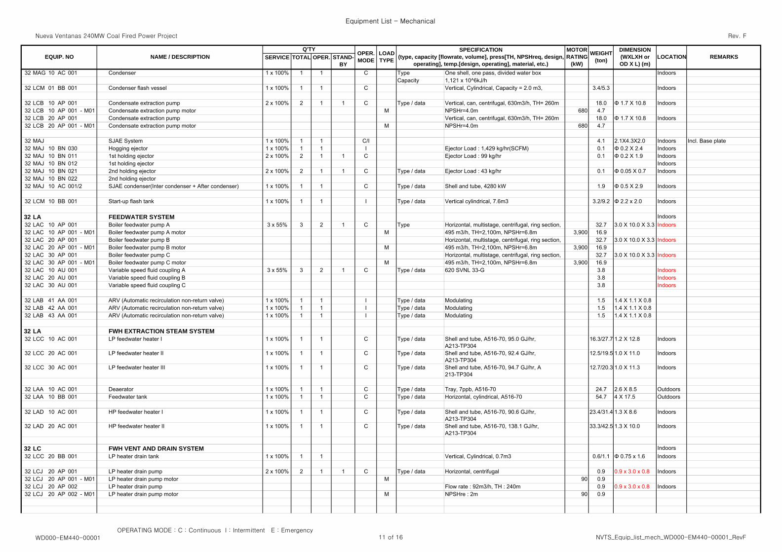
32 MAG 10 AC 001 Condenser 1 x 100% 1 1 C Type One shell, one pass, divided water box IndoorsCapacity 1,121 x 10^6kJ/h
32 LCM 01 BB 001 Condenser flash vessel 1 x 100% 1 1 C Vertical, Cylindrical, Capacity = 2.0 m3, 3.4/5.3 Indoors
32 LCB 10 AP 001 Condensate extraction pump 2 x 100% 2 1 1 C Type / data Vertical, can, centrifugal, 630m3/h, TH= 260m 18.0 Φ 1.7 X 10.8 Indoors32 LCB 10 AP 001 - M01 Condensate extraction pump motor M NPSHr=4.0m 680 4.732 LCB 20 AP 001 Condensate extraction pump Vertical, can, centrifugal, 630m3/h, TH= 260m 18.0 Φ 1.7 X 10.8 Indoors32 LCB 20 AP 001 - M01 Condensate extraction pump motor M NPSHr=4.0m 680 4.7
32 MAJ SJAE System 1 x 100% 1 1 C/I 4.1 2.1X4.3X2.0 Indoors Incl. Base plate32 MAJ 10 BN 030 Hogging ejector 1 x 100% 1 1 I Ejector Load : 1,429 kg/hr(SCFM) 0.1 Φ 0.2 X 2.4 Indoors32 MAJ 10 BN 011 1st holding ejector 2 x 100% 2 1 1 C Ejector Load : 99 kg/hr 0.1 Φ 0.2 X 1.9 Indoors32 MAJ 10 BN 012 1st holding ejector Indoors32 MAJ 10 BN 021 2nd holding ejector 2 x 100% 2 1 1 C Type / data Ejector Load : 43 kg/hr 0.1 Φ 0.05 X 0.7 Indoors32 MAJ 10 BN 022 2nd holding ejector32 MAJ 10 AC 001/2 SJAE condenser(Inter condenser + After condenser) 1 x 100% 1 1 C Type / data Shell and tube, 4280 kW 1.9 Φ 0.5 X 2.9 Indoors
32 LCM 10 BB 001 Start-up flash tank 1 x 100% 1 1 I Type / data Vertical cylindrical, 7.6m3 3.2/9.2 Φ 2.2 x 2.0 Indoors
32 LA FEEDWATER SYSTEM Indoors32 LAC 10 AP 001 Boiler feedwater pump A 3 x 55% 3 2 1 C Type Horizontal, multistage, centrifugal, ring section, 32.7 3.0 X 10.0 X 3.3 Indoors32 LAC 10 AP 001 - M01 Boiler feedwater pump A motor M 495 m3/h, TH=2,100m, NPSHr=6.8m 3,900 16.932 LAC 20 AP 001 Boiler feedwater pump B Horizontal, multistage, centrifugal, ring section, 32.7 3.0 X 10.0 X 3.3 Indoors32 LAC 20 AP 001 - M01 Boiler feedwater pump B motor M 495 m3/h, TH=2,100m, NPSHr=6.8m 3,900 16.932 LAC 30 AP 001 Boiler feedwater pump C Horizontal, multistage, centrifugal, ring section, 32.7 3.0 X 10.0 X 3.3 Indoors32 LAC 30 AP 001 - M01 Boiler feedwater pump C motor M 495 m3/h, TH=2,100m, NPSHr=6.8m 3,900 16.932 LAC 10 AU 001 Variable speed fluid coupling A 3 x 55% 3 2 1 C Type / data 620 SVNL 33-G 3.8 Indoors32 LAC 20 AU 001 Variable speed fluid coupling B 3.8 Indoors32 LAC 30 AU 001 Variable speed fluid coupling C 3.8 Indoors
32 LAB 41 AA 001 ARV (Automatic recirculation non-return valve) 1 x 100% 1 1 I Type / data Modulating 1.5 1.4 X 1.1 X 0.8 32 LAB 42 AA 001 ARV (Automatic recirculation non-return valve) 1 x 100% 1 1 I Type / data Modulating 1.5 1.4 X 1.1 X 0.8 32 LAB 43 AA 001 ARV (Automatic recirculation non-return valve) 1 x 100% 1 1 I Type / data Modulating 1.5 1.4 X 1.1 X 0.8
32 LA FWH EXTRACTION STEAM SYSTEM32 LCC 10 AC 001 LP feedwater heater I 1 x 100% 1 1 C Type / data Shell and tube, A516-70, 95.0 GJ/hr,
A213-TP30416.3/27.7 1.2 X 12.8 Indoors
32 LCC 20 AC 001 LP feedwater heater II 1 x 100% 1 1 C Type / data Shell and tube, A516-70, 92.4 GJ/hr,A213-TP304
12.5/19.5 1.0 X 11.0 Indoors
32 LCC 30 AC 001 LP feedwater heater III 1 x 100% 1 1 C Type / data Shell and tube, A516-70, 94.7 GJ/hr, A213-TP304
12.7/20.3 1.0 X 11.3 Indoors
32 LAA 10 AC 001 Deaerator 1 x 100% 1 1 C Type / data Tray, 7ppb, A516-70 24.7 2.6 X 8.5 Outdoors32 LAA 10 BB 001 Feedwater tank 1 x 100% 1 1 C Type / data Horizontal, cylindrical, A516-70 54.7 4 X 17.5 Outdoors
32 LAD 10 AC 001 HP feedwater heater I 1 x 100% 1 1 C Type / data Shell and tube, A516-70, 90.6 GJ/hr,A213-TP304
23.4/31.4 1.3 X 8.6 Indoors
32 LAD 20 AC 001 HP feedwater heater II 1 x 100% 1 1 C Type / data Shell and tube, A516-70, 138.1 GJ/hr,A213-TP304
33.3/42.5 1.3 X 10.0 Indoors
32 LC FWH VENT AND DRAIN SYSTEM Indoors32 LCC 20 BB 001 LP heater drain tank 1 x 100% 1 1 Vertical, Cylindrical, 0.7m3 0.6/1.1 Φ 0.75 x 1.6 Indoors
32 LCJ 20 AP 001 LP heater drain pump 2 x 100% 2 1 1 C Type / data Horizontal, centrifugal 0.9 0.9 x 3.0 x 0.8 Indoors32 LCJ 20 AP 001 - M01 LP heater drain pump motor M 90 0.932 LCJ 20 AP 002 LP heater drain pump Flow rate : 92m3/h, TH : 240m 0.9 0.9 x 3.0 x 0.8 Indoors32 LCJ 20 AP 002 - M01 LP heater drain pump motor M NPSHre : 2m 90 0.9
OPERATING MODE : C : Continuous I : Intermittent E : EmergencyWD000-EM440-00001 11 of 16 NVTS_Equip_list_mech_WD000-EM440-00001_RevF
Nueva Ventanas 240MW Coal Fired Power Project
Equipment List - Mechanical
Rev. F
SERVICE TOTAL OPER.MOTORRATING
(kW)
OPER.MODE
LOADTYPE REMARKSWEIGHT
(ton)
DIMENSION(WXLXH orOD X L) (m)
LOCATIONSPECIFICATION
(type, capacity [flowrate, volume], press[TH, NPSHreq, design,operating], temp.[design, operating], material, etc.)
STAND-BY
EQUIP. NOQ'TY
NAME / DESCRIPTION
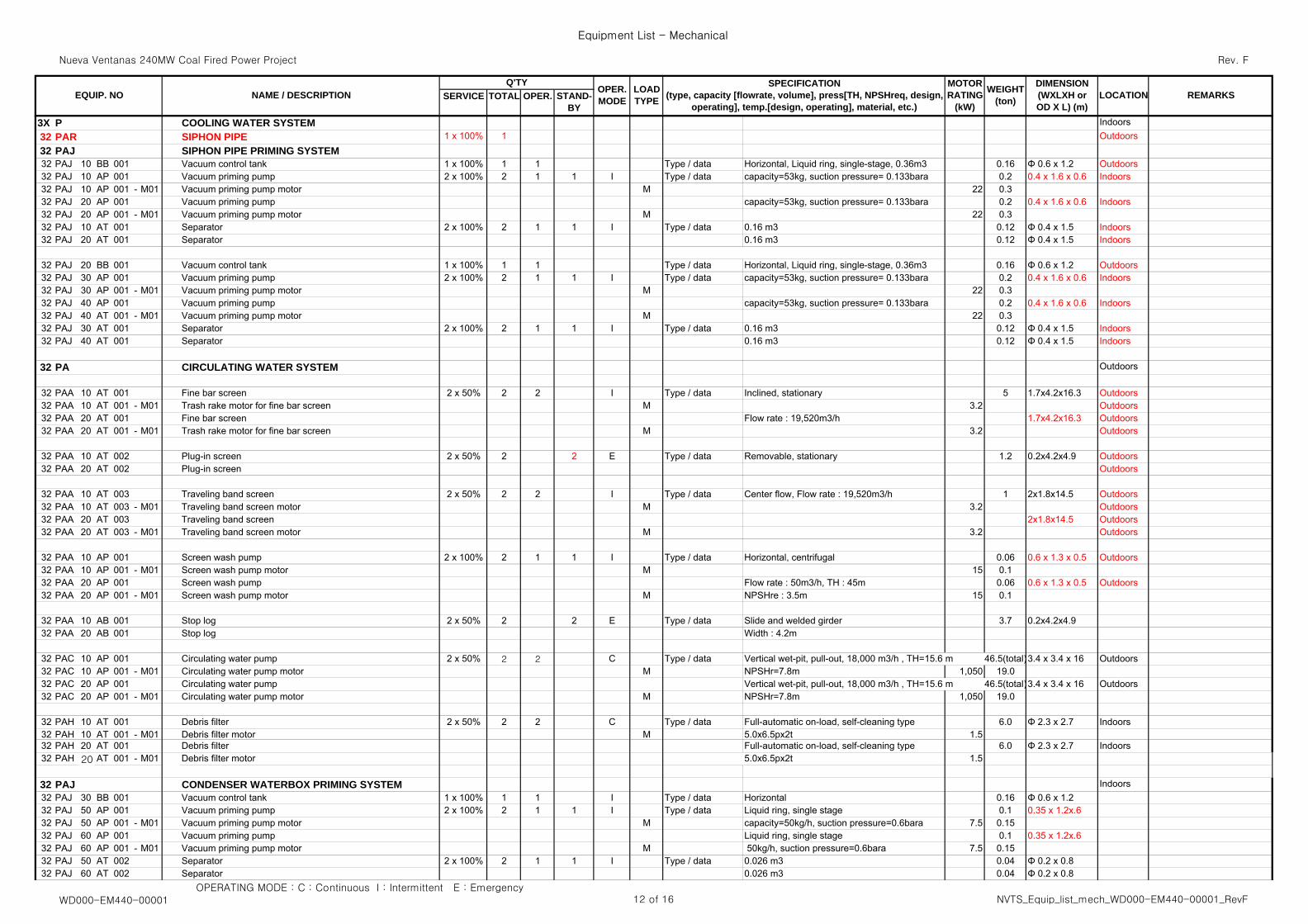
3X P COOLING WATER SYSTEM Indoors32 PAR SIPHON PIPE 1 x 100% 1 Outdoors32 PAJ SIPHON PIPE PRIMING SYSTEM32 PAJ 10 BB 001 Vacuum control tank 1 x 100% 1 1 Type / data Horizontal, Liquid ring, single-stage, 0.36m3 0.16 Φ 0.6 x 1.2 Outdoors32 PAJ 10 AP 001 Vacuum priming pump 2 x 100% 2 1 1 I Type / data capacity=53kg, suction pressure= 0.133bara 0.2 0.4 x 1.6 x 0.6 Indoors32 PAJ 10 AP 001 - M01 Vacuum priming pump motor M 22 0.332 PAJ 20 AP 001 Vacuum priming pump capacity=53kg, suction pressure= 0.133bara 0.2 0.4 x 1.6 x 0.6 Indoors32 PAJ 20 AP 001 - M01 Vacuum priming pump motor M 22 0.332 PAJ 10 AT 001 Separator 2 x 100% 2 1 1 I Type / data 0.16 m3 0.12 Φ 0.4 x 1.5 Indoors32 PAJ 20 AT 001 Separator 0.16 m3 0.12 Φ 0.4 x 1.5 Indoors
32 PAJ 20 BB 001 Vacuum control tank 1 x 100% 1 1 Type / data Horizontal, Liquid ring, single-stage, 0.36m3 0.16 Φ 0.6 x 1.2 Outdoors32 PAJ 30 AP 001 Vacuum priming pump 2 x 100% 2 1 1 I Type / data capacity=53kg, suction pressure= 0.133bara 0.2 0.4 x 1.6 x 0.6 Indoors32 PAJ 30 AP 001 - M01 Vacuum priming pump motor M 22 0.332 PAJ 40 AP 001 Vacuum priming pump capacity=53kg, suction pressure= 0.133bara 0.2 0.4 x 1.6 x 0.6 Indoors32 PAJ 40 AT 001 - M01 Vacuum priming pump motor M 22 0.332 PAJ 30 AT 001 Separator 2 x 100% 2 1 1 I Type / data 0.16 m3 0.12 Φ 0.4 x 1.5 Indoors32 PAJ 40 AT 001 Separator 0.16 m3 0.12 Φ 0.4 x 1.5 Indoors
32 PA CIRCULATING WATER SYSTEM Outdoors
32 PAA 10 AT 001 Fine bar screen 2 x 50% 2 2 I Type / data Inclined, stationary 5 1.7x4.2x16.3 Outdoors32 PAA 10 AT 001 - M01 Trash rake motor for fine bar screen M 3.2 Outdoors32 PAA 20 AT 001 Fine bar screen Flow rate : 19,520m3/h 1.7x4.2x16.3 Outdoors32 PAA 20 AT 001 - M01 Trash rake motor for fine bar screen M 3.2 Outdoors
32 PAA 10 AT 002 Plug-in screen 2 x 50% 2 2 E Type / data Removable, stationary 1.2 0.2x4.2x4.9 Outdoors32 PAA 20 AT 002 Plug-in screen Outdoors
32 PAA 10 AT 003 Traveling band screen 2 x 50% 2 2 I Type / data Center flow, Flow rate : 19,520m3/h 1 2x1.8x14.5 Outdoors32 PAA 10 AT 003 - M01 Traveling band screen motor M 3.2 Outdoors32 PAA 20 AT 003 Traveling band screen 2x1.8x14.5 Outdoors32 PAA 20 AT 003 - M01 Traveling band screen motor M 3.2 Outdoors
32 PAA 10 AP 001 Screen wash pump 2 x 100% 2 1 1 I Type / data Horizontal, centrifugal 0.06 0.6 x 1.3 x 0.5 Outdoors32 PAA 10 AP 001 - M01 Screen wash pump motor M 15 0.132 PAA 20 AP 001 Screen wash pump Flow rate : 50m3/h, TH : 45m 0.06 0.6 x 1.3 x 0.5 Outdoors32 PAA 20 AP 001 - M01 Screen wash pump motor M NPSHre : 3.5m 15 0.1
32 PAA 10 AB 001 Stop log 2 x 50% 2 2 E Type / data Slide and welded girder 3.7 0.2x4.2x4.932 PAA 20 AB 001 Stop log Width : 4.2m
32 PAC 10 AP 001 Circulating water pump 2 x 50% 2 2 C Type / data Vertical wet-pit, pull-out, 18,000 m3/h , TH=15.6 m 46.5(total)3.4 x 3.4 x 16 Outdoors32 PAC 10 AP 001 - M01 Circulating water pump motor M NPSHr=7.8m 1,050 19.032 PAC 20 AP 001 Circulating water pump Vertical wet-pit, pull-out, 18,000 m3/h , TH=15.6 m 46.5(total)3.4 x 3.4 x 16 Outdoors32 PAC 20 AP 001 - M01 Circulating water pump motor M NPSHr=7.8m 1,050 19.0
32 PAH 10 AT 001 Debris filter 2 x 50% 2 2 C Type / data Full-automatic on-load, self-cleaning type 6.0 Φ 2.3 x 2.7 Indoors32 PAH 10 AT 001 - M01 Debris filter motor M 5.0x6.5px2t 1.532 PAH 20 AT 001 Debris filter Full-automatic on-load, self-cleaning type 6.0 Φ 2.3 x 2.7 Indoors32 PAH 20 AT 001 - M01 Debris filter motor 5.0x6.5px2t 1.5
32 PAJ CONDENSER WATERBOX PRIMING SYSTEM Indoors32 PAJ 30 BB 001 Vacuum control tank 1 x 100% 1 1 I Type / data Horizontal 0.16 Φ 0.6 x 1.2 32 PAJ 50 AP 001 Vacuum priming pump 2 x 100% 2 1 1 I Type / data Liquid ring, single stage 0.1 0.35 x 1.2x.632 PAJ 50 AP 001 - M01 Vacuum priming pump motor M capacity=50kg/h, suction pressure=0.6bara 7.5 0.1532 PAJ 60 AP 001 Vacuum priming pump Liquid ring, single stage 0.1 0.35 x 1.2x.632 PAJ 60 AP 001 - M01 Vacuum priming pump motor M 50kg/h, suction pressure=0.6bara 7.5 0.1532 PAJ 50 AT 002 Separator 2 x 100% 2 1 1 I Type / data 0.026 m3 0.04 Φ 0.2 x 0.832 PAJ 60 AT 002 Separator 0.026 m3 0.04 Φ 0.2 x 0.8
OPERATING MODE : C : Continuous I : Intermittent E : EmergencyWD000-EM440-00001 12 of 16 NVTS_Equip_list_mech_WD000-EM440-00001_RevF
Nueva Ventanas 240MW Coal Fired Power Project
Equipment List - Mechanical
Rev. F
SERVICE TOTAL OPER.MOTORRATING
(kW)
OPER.MODE
LOADTYPE REMARKSWEIGHT
(ton)
DIMENSION(WXLXH orOD X L) (m)
LOCATIONSPECIFICATION
(type, capacity [flowrate, volume], press[TH, NPSHreq, design,operating], temp.[design, operating], material, etc.)
STAND-BY
EQUIP. NOQ'TY
NAME / DESCRIPTION
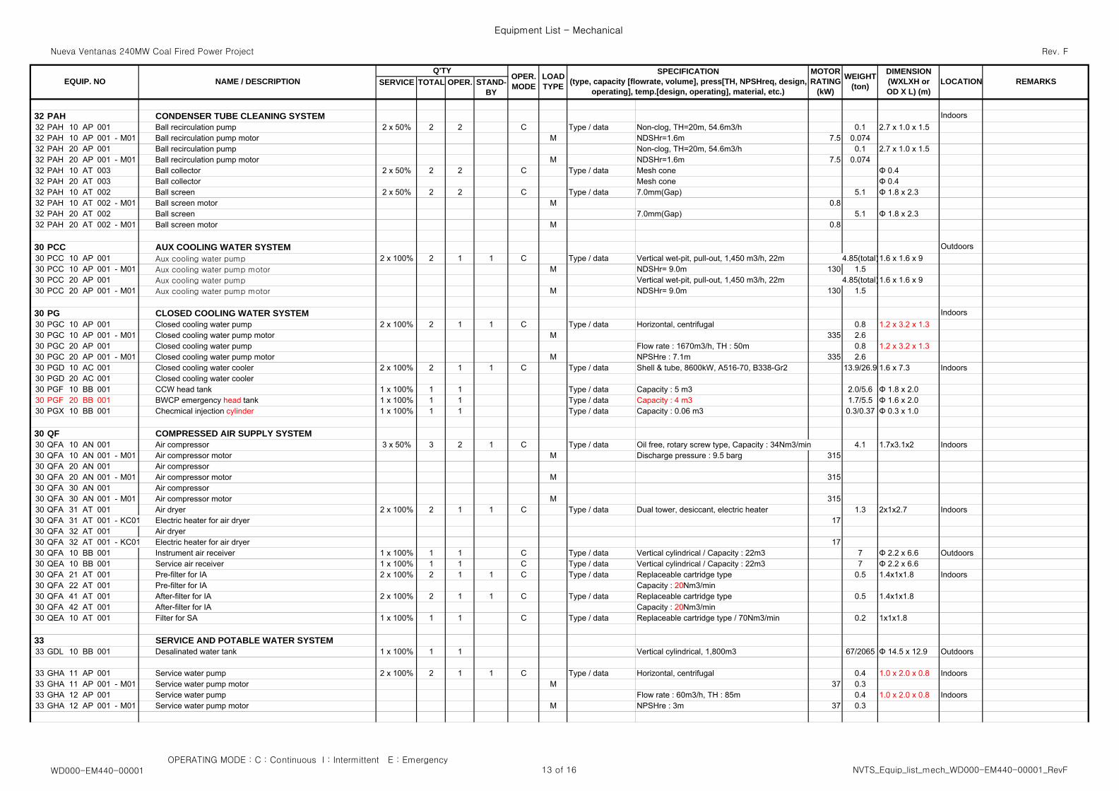
32 PAH CONDENSER TUBE CLEANING SYSTEM Indoors32 PAH 10 AP 001 Ball recirculation pump 2 x 50% 2 2 C Type / data Non-clog, TH=20m, 54.6m3/h 0.1 2.7 x 1.0 x 1.532 PAH 10 AP 001 - M01 Ball recirculation pump motor M NDSHr=1.6m 7.5 0.07432 PAH 20 AP 001 Ball recirculation pump Non-clog, TH=20m, 54.6m3/h 0.1 2.7 x 1.0 x 1.532 PAH 20 AP 001 - M01 Ball recirculation pump motor M NDSHr=1.6m 7.5 0.07432 PAH 10 AT 003 Ball collector 2 x 50% 2 2 C Type / data Mesh cone Φ 0.432 PAH 20 AT 003 Ball collector Mesh cone Φ 0.432 PAH 10 AT 002 Ball screen 2 x 50% 2 2 C Type / data 7.0mm(Gap) 5.1 Φ 1.8 x 2.332 PAH 10 AT 002 - M01 Ball screen motor M 0.832 PAH 20 AT 002 Ball screen 7.0mm(Gap) 5.1 Φ 1.8 x 2.332 PAH 20 AT 002 - M01 Ball screen motor M 0.8
30 PCC AUX COOLING WATER SYSTEM Outdoors30 PCC 10 AP 001 Aux cooling water pump 2 x 100% 2 1 1 C Type / data Vertical wet-pit, pull-out, 1,450 m3/h, 22m 4.85(total)1.6 x 1.6 x 930 PCC 10 AP 001 - M01 Aux cooling water pump motor M NDSHr= 9.0m 130 1.530 PCC 20 AP 001 Aux cooling water pump Vertical wet-pit, pull-out, 1,450 m3/h, 22m 4.85(total)1.6 x 1.6 x 930 PCC 20 AP 001 - M01 Aux cooling water pump motor M NDSHr= 9.0m 130 1.5
30 PG CLOSED COOLING WATER SYSTEM Indoors30 PGC 10 AP 001 Closed cooling water pump 2 x 100% 2 1 1 C Type / data Horizontal, centrifugal 0.8 1.2 x 3.2 x 1.330 PGC 10 AP 001 - M01 Closed cooling water pump motor M 335 2.630 PGC 20 AP 001 Closed cooling water pump Flow rate : 1670m3/h, TH : 50m 0.8 1.2 x 3.2 x 1.330 PGC 20 AP 001 - M01 Closed cooling water pump motor M NPSHre : 7.1m 335 2.630 PGD 10 AC 001 Closed cooling water cooler 2 x 100% 2 1 1 C Type / data Shell & tube, 8600kW, A516-70, B338-Gr2 13.9/26.9 1.6 x 7.3 Indoors30 PGD 20 AC 001 Closed cooling water cooler30 PGF 10 BB 001 CCW head tank 1 x 100% 1 1 Type / data Capacity : 5 m3 2.0/5.6 Φ 1.8 x 2.030 PGF 20 BB 001 BWCP emergency head tank 1 x 100% 1 1 Type / data Capacity : 4 m3 1.7/5.5 Φ 1.6 x 2.030 PGX 10 BB 001 Checmical injection cylinder 1 x 100% 1 1 Type / data Capacity : 0.06 m3 0.3/0.37 Φ 0.3 x 1.0
30 QF COMPRESSED AIR SUPPLY SYSTEM30 QFA 10 AN 001 Air compressor 3 x 50% 3 2 1 C Type / data Oil free, rotary screw type, Capacity : 34Nm3/min 4.1 1.7x3.1x2 Indoors30 QFA 10 AN 001 - M01 Air compressor motor M Discharge pressure : 9.5 barg 31530 QFA 20 AN 001 Air compressor30 QFA 20 AN 001 - M01 Air compressor motor M 31530 QFA 30 AN 001 Air compressor30 QFA 30 AN 001 - M01 Air compressor motor M 31530 QFA 31 AT 001 Air dryer 2 x 100% 2 1 1 C Type / data Dual tower, desiccant, electric heater 1.3 2x1x2.7 Indoors30 QFA 31 AT 001 - KC01 Electric heater for air dryer 1730 QFA 32 AT 001 Air dryer30 QFA 32 AT 001 - KC01 Electric heater for air dryer 1730 QFA 10 BB 001 Instrument air receiver 1 x 100% 1 1 C Type / data Vertical cylindrical / Capacity : 22m3 7 Φ 2.2 x 6.6 Outdoors30 QEA 10 BB 001 Service air receiver 1 x 100% 1 1 C Type / data Vertical cylindrical / Capacity : 22m3 7 Φ 2.2 x 6.630 QFA 21 AT 001 Pre-filter for IA 2 x 100% 2 1 1 C Type / data Replaceable cartridge type 0.5 1.4x1x1.8 Indoors30 QFA 22 AT 001 Pre-filter for IA Capacity : 20Nm3/min30 QFA 41 AT 001 After-filter for IA 2 x 100% 2 1 1 C Type / data Replaceable cartridge type 0.5 1.4x1x1.830 QFA 42 AT 001 After-filter for IA Capacity : 20Nm3/min30 QEA 10 AT 001 Filter for SA 1 x 100% 1 1 C Type / data Replaceable cartridge type / 70Nm3/min 0.2 1x1x1.8
33 SERVICE AND POTABLE WATER SYSTEM33 GDL 10 BB 001 Desalinated water tank 1 x 100% 1 1 Vertical cylindrical, 1,800m3 67/2065 Φ 14.5 x 12.9 Outdoors
33 GHA 11 AP 001 Service water pump 2 x 100% 2 1 1 C Type / data Horizontal, centrifugal 0.4 1.0 x 2.0 x 0.8 Indoors33 GHA 11 AP 001 - M01 Service water pump motor M 37 0.333 GHA 12 AP 001 Service water pump Flow rate : 60m3/h, TH : 85m 0.4 1.0 x 2.0 x 0.8 Indoors33 GHA 12 AP 001 - M01 Service water pump motor M NPSHre : 3m 37 0.3
OPERATING MODE : C : Continuous I : Intermittent E : EmergencyWD000-EM440-00001 13 of 16 NVTS_Equip_list_mech_WD000-EM440-00001_RevF
Nueva Ventanas 240MW Coal Fired Power Project
Equipment List - Mechanical
Rev. F
SERVICE TOTAL OPER.MOTORRATING
(kW)
OPER.MODE
LOADTYPE REMARKSWEIGHT
(ton)
DIMENSION(WXLXH orOD X L) (m)
LOCATIONSPECIFICATION
(type, capacity [flowrate, volume], press[TH, NPSHreq, design,operating], temp.[design, operating], material, etc.)
STAND-BY
EQUIP. NOQ'TY
NAME / DESCRIPTION
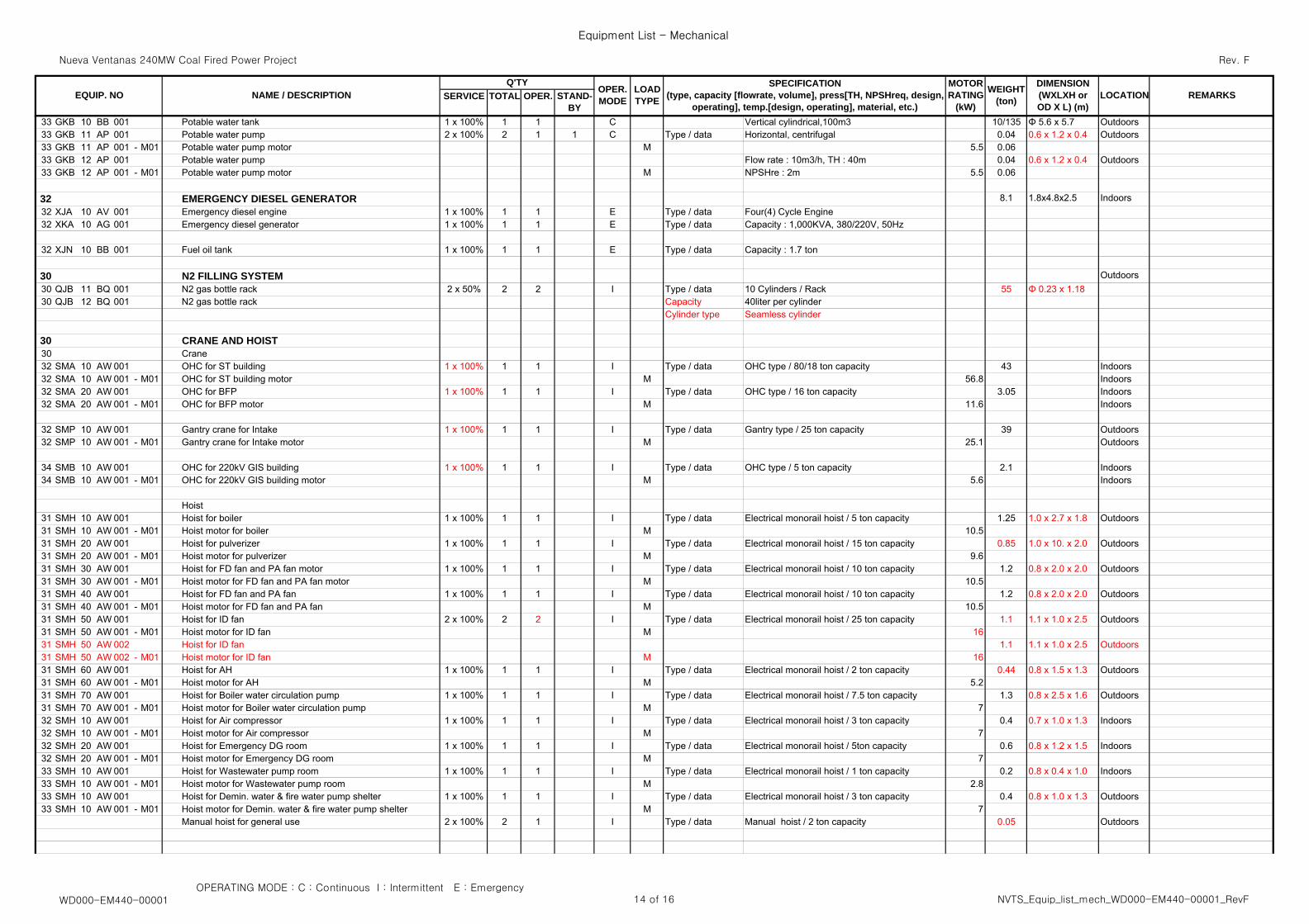
33 GKB 10 BB 001 Potable water tank 1 x 100% 1 1 C Vertical cylindrical,100m3 10/135 Φ 5.6 x 5.7 Outdoors33 GKB 11 AP 001 Potable water pump 2 x 100% 2 1 1 C Type / data Horizontal, centrifugal 0.04 0.6 x 1.2 x 0.4 Outdoors33 GKB 11 AP 001 - M01 Potable water pump motor M 5.5 0.0633 GKB 12 AP 001 Potable water pump Flow rate : 10m3/h, TH : 40m 0.04 0.6 x 1.2 x 0.4 Outdoors33 GKB 12 AP 001 - M01 Potable water pump motor M NPSHre : 2m 5.5 0.06
32 EMERGENCY DIESEL GENERATOR 8.1 1.8x4.8x2.5 Indoors32 XJA 10 AV 001 Emergency diesel engine 1 x 100% 1 1 E Type / data Four(4) Cycle Engine32 XKA 10 AG 001 Emergency diesel generator 1 x 100% 1 1 E Type / data Capacity : 1,000KVA, 380/220V, 50Hz
32 XJN 10 BB 001 Fuel oil tank 1 x 100% 1 1 E Type / data Capacity : 1.7 ton
30 N2 FILLING SYSTEM Outdoors30 QJB 11 BQ 001 N2 gas bottle rack 2 x 50% 2 2 I Type / data 10 Cylinders / Rack 55 Φ 0.23 x 1.1830 QJB 12 BQ 001 N2 gas bottle rack Capacity 40liter per cylinder
Cylinder type Seamless cylinder
30 CRANE AND HOIST30 Crane32 SMA 10 AW 001 OHC for ST building 1 x 100% 1 1 I Type / data OHC type / 80/18 ton capacity 43 Indoors32 SMA 10 AW 001 - M01 OHC for ST building motor M 56.8 Indoors32 SMA 20 AW 001 OHC for BFP 1 x 100% 1 1 I Type / data OHC type / 16 ton capacity 3.05 Indoors32 SMA 20 AW 001 - M01 OHC for BFP motor M 11.6 Indoors
32 SMP 10 AW 001 Gantry crane for Intake 1 x 100% 1 1 I Type / data Gantry type / 25 ton capacity 39 Outdoors32 SMP 10 AW 001 - M01 Gantry crane for Intake motor M 25.1 Outdoors
34 SMB 10 AW 001 OHC for 220kV GIS building 1 x 100% 1 1 I Type / data OHC type / 5 ton capacity 2.1 Indoors34 SMB 10 AW 001 - M01 OHC for 220kV GIS building motor M 5.6 Indoors
Hoist31 SMH 10 AW 001 Hoist for boiler 1 x 100% 1 1 I Type / data Electrical monorail hoist / 5 ton capacity 1.25 1.0 x 2.7 x 1.8 Outdoors31 SMH 10 AW 001 - M01 Hoist motor for boiler M 10.531 SMH 20 AW 001 Hoist for pulverizer 1 x 100% 1 1 I Type / data Electrical monorail hoist / 15 ton capacity 0.85 1.0 x 10. x 2.0 Outdoors31 SMH 20 AW 001 - M01 Hoist motor for pulverizer M 9.631 SMH 30 AW 001 Hoist for FD fan and PA fan motor 1 x 100% 1 1 I Type / data Electrical monorail hoist / 10 ton capacity 1.2 0.8 x 2.0 x 2.0 Outdoors31 SMH 30 AW 001 - M01 Hoist motor for FD fan and PA fan motor M 10.531 SMH 40 AW 001 Hoist for FD fan and PA fan 1 x 100% 1 1 I Type / data Electrical monorail hoist / 10 ton capacity 1.2 0.8 x 2.0 x 2.0 Outdoors31 SMH 40 AW 001 - M01 Hoist motor for FD fan and PA fan M 10.531 SMH 50 AW 001 Hoist for ID fan 2 x 100% 2 2 I Type / data Electrical monorail hoist / 25 ton capacity 1.1 1.1 x 1.0 x 2.5 Outdoors31 SMH 50 AW 001 - M01 Hoist motor for ID fan M 1631 SMH 50 AW 002 Hoist for ID fan 1.1 1.1 x 1.0 x 2.5 Outdoors31 SMH 50 AW 002 - M01 Hoist motor for ID fan M 1631 SMH 60 AW 001 Hoist for AH 1 x 100% 1 1 I Type / data Electrical monorail hoist / 2 ton capacity 0.44 0.8 x 1.5 x 1.3 Outdoors31 SMH 60 AW 001 - M01 Hoist motor for AH M 5.231 SMH 70 AW 001 Hoist for Boiler water circulation pump 1 x 100% 1 1 I Type / data Electrical monorail hoist / 7.5 ton capacity 1.3 0.8 x 2.5 x 1.6 Outdoors31 SMH 70 AW 001 - M01 Hoist motor for Boiler water circulation pump M 732 SMH 10 AW 001 Hoist for Air compressor 1 x 100% 1 1 I Type / data Electrical monorail hoist / 3 ton capacity 0.4 0.7 x 1.0 x 1.3 Indoors32 SMH 10 AW 001 - M01 Hoist motor for Air compressor M 732 SMH 20 AW 001 Hoist for Emergency DG room 1 x 100% 1 1 I Type / data Electrical monorail hoist / 5ton capacity 0.6 0.8 x 1.2 x 1.5 Indoors32 SMH 20 AW 001 - M01 Hoist motor for Emergency DG room M 733 SMH 10 AW 001 Hoist for Wastewater pump room 1 x 100% 1 1 I Type / data Electrical monorail hoist / 1 ton capacity 0.2 0.8 x 0.4 x 1.0 Indoors33 SMH 10 AW 001 - M01 Hoist motor for Wastewater pump room M 2.833 SMH 10 AW 001 Hoist for Demin. water & fire water pump shelter 1 x 100% 1 1 I Type / data Electrical monorail hoist / 3 ton capacity 0.4 0.8 x 1.0 x 1.3 Outdoors33 SMH 10 AW 001 - M01 Hoist motor for Demin. water & fire water pump shelter M 7
Manual hoist for general use 2 x 100% 2 1 I Type / data Manual hoist / 2 ton capacity 0.05 Outdoors
OPERATING MODE : C : Continuous I : Intermittent E : EmergencyWD000-EM440-00001 14 of 16 NVTS_Equip_list_mech_WD000-EM440-00001_RevF
Nueva Ventanas 240MW Coal Fired Power Project
Equipment List - Mechanical
Rev. F
SERVICE TOTAL OPER.MOTORRATING
(kW)
OPER.MODE
LOADTYPE REMARKSWEIGHT
(ton)
DIMENSION(WXLXH orOD X L) (m)
LOCATIONSPECIFICATION
(type, capacity [flowrate, volume], press[TH, NPSHreq, design,operating], temp.[design, operating], material, etc.)
STAND-BY
EQUIP. NOQ'TY
NAME / DESCRIPTION
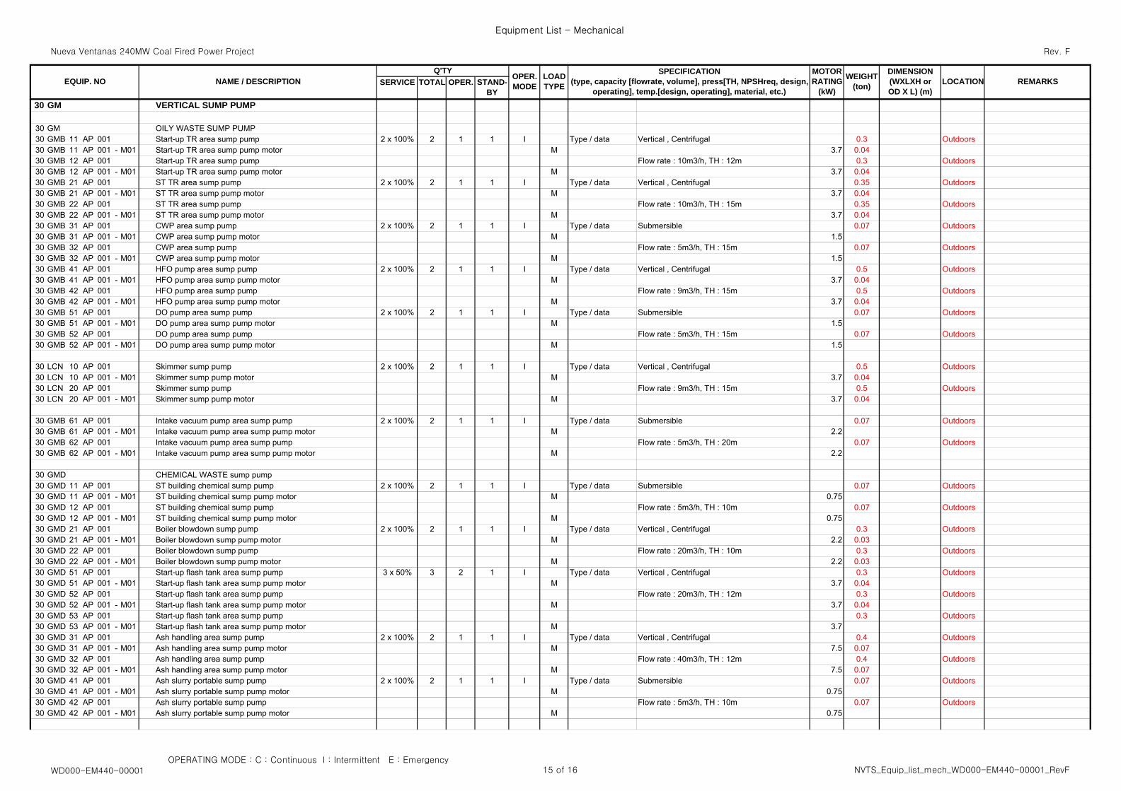
30 GM VERTICAL SUMP PUMP
30 GM OILY WASTE SUMP PUMP30 GMB 11 AP 001 Start-up TR area sump pump 2 x 100% 2 1 1 I Type / data Vertical , Centrifugal 0.3 Outdoors30 GMB 11 AP 001 - M01 Start-up TR area sump pump motor M 3.7 0.0430 GMB 12 AP 001 Start-up TR area sump pump Flow rate : 10m3/h, TH : 12m 0.3 Outdoors30 GMB 12 AP 001 - M01 Start-up TR area sump pump motor M 3.7 0.0430 GMB 21 AP 001 ST TR area sump pump 2 x 100% 2 1 1 I Type / data Vertical , Centrifugal 0.35 Outdoors30 GMB 21 AP 001 - M01 ST TR area sump pump motor M 3.7 0.0430 GMB 22 AP 001 ST TR area sump pump Flow rate : 10m3/h, TH : 15m 0.35 Outdoors30 GMB 22 AP 001 - M01 ST TR area sump pump motor M 3.7 0.0430 GMB 31 AP 001 CWP area sump pump 2 x 100% 2 1 1 I Type / data Submersible 0.07 Outdoors30 GMB 31 AP 001 - M01 CWP area sump pump motor M 1.530 GMB 32 AP 001 CWP area sump pump Flow rate : 5m3/h, TH : 15m 0.07 Outdoors30 GMB 32 AP 001 - M01 CWP area sump pump motor M 1.530 GMB 41 AP 001 HFO pump area sump pump 2 x 100% 2 1 1 I Type / data Vertical , Centrifugal 0.5 Outdoors30 GMB 41 AP 001 - M01 HFO pump area sump pump motor M 3.7 0.0430 GMB 42 AP 001 HFO pump area sump pump Flow rate : 9m3/h, TH : 15m 0.5 Outdoors30 GMB 42 AP 001 - M01 HFO pump area sump pump motor M 3.7 0.0430 GMB 51 AP 001 DO pump area sump pump 2 x 100% 2 1 1 I Type / data Submersible 0.07 Outdoors30 GMB 51 AP 001 - M01 DO pump area sump pump motor M 1.530 GMB 52 AP 001 DO pump area sump pump Flow rate : 5m3/h, TH : 15m 0.07 Outdoors30 GMB 52 AP 001 - M01 DO pump area sump pump motor M 1.5
30 LCN 10 AP 001 Skimmer sump pump 2 x 100% 2 1 1 I Type / data Vertical , Centrifugal 0.5 Outdoors30 LCN 10 AP 001 - M01 Skimmer sump pump motor M 3.7 0.0430 LCN 20 AP 001 Skimmer sump pump Flow rate : 9m3/h, TH : 15m 0.5 Outdoors30 LCN 20 AP 001 - M01 Skimmer sump pump motor M 3.7 0.04
30 GMB 61 AP 001 Intake vacuum pump area sump pump 2 x 100% 2 1 1 I Type / data Submersible 0.07 Outdoors30 GMB 61 AP 001 - M01 Intake vacuum pump area sump pump motor M 2.230 GMB 62 AP 001 Intake vacuum pump area sump pump Flow rate : 5m3/h, TH : 20m 0.07 Outdoors30 GMB 62 AP 001 - M01 Intake vacuum pump area sump pump motor M 2.2
30 GMD CHEMICAL WASTE sump pump30 GMD 11 AP 001 ST building chemical sump pump 2 x 100% 2 1 1 I Type / data Submersible 0.07 Outdoors30 GMD 11 AP 001 - M01 ST building chemical sump pump motor M 0.7530 GMD 12 AP 001 ST building chemical sump pump Flow rate : 5m3/h, TH : 10m 0.07 Outdoors30 GMD 12 AP 001 - M01 ST building chemical sump pump motor M 0.7530 GMD 21 AP 001 Boiler blowdown sump pump 2 x 100% 2 1 1 I Type / data Vertical , Centrifugal 0.3 Outdoors30 GMD 21 AP 001 - M01 Boiler blowdown sump pump motor M 2.2 0.0330 GMD 22 AP 001 Boiler blowdown sump pump Flow rate : 20m3/h, TH : 10m 0.3 Outdoors30 GMD 22 AP 001 - M01 Boiler blowdown sump pump motor M 2.2 0.0330 GMD 51 AP 001 Start-up flash tank area sump pump 3 x 50% 3 2 1 I Type / data Vertical , Centrifugal 0.3 Outdoors30 GMD 51 AP 001 - M01 Start-up flash tank area sump pump motor M 3.7 0.0430 GMD 52 AP 001 Start-up flash tank area sump pump Flow rate : 20m3/h, TH : 12m 0.3 Outdoors30 GMD 52 AP 001 - M01 Start-up flash tank area sump pump motor M 3.7 0.0430 GMD 53 AP 001 Start-up flash tank area sump pump 0.3 Outdoors30 GMD 53 AP 001 - M01 Start-up flash tank area sump pump motor M 3.730 GMD 31 AP 001 Ash handling area sump pump 2 x 100% 2 1 1 I Type / data Vertical , Centrifugal 0.4 Outdoors30 GMD 31 AP 001 - M01 Ash handling area sump pump motor M 7.5 0.0730 GMD 32 AP 001 Ash handling area sump pump Flow rate : 40m3/h, TH : 12m 0.4 Outdoors30 GMD 32 AP 001 - M01 Ash handling area sump pump motor M 7.5 0.0730 GMD 41 AP 001 Ash slurry portable sump pump 2 x 100% 2 1 1 I Type / data Submersible 0.07 Outdoors30 GMD 41 AP 001 - M01 Ash slurry portable sump pump motor M 0.7530 GMD 42 AP 001 Ash slurry portable sump pump Flow rate : 5m3/h, TH : 10m 0.07 Outdoors30 GMD 42 AP 001 - M01 Ash slurry portable sump pump motor M 0.75
OPERATING MODE : C : Continuous I : Intermittent E : EmergencyWD000-EM440-00001 15 of 16 NVTS_Equip_list_mech_WD000-EM440-00001_RevF
Nueva Ventanas 240MW Coal Fired Power Project
Equipment List - Mechanical
Rev. F
SERVICE TOTAL OPER.MOTORRATING
(kW)
OPER.MODE
LOADTYPE REMARKSWEIGHT
(ton)
DIMENSION(WXLXH orOD X L) (m)
LOCATIONSPECIFICATION
(type, capacity [flowrate, volume], press[TH, NPSHreq, design,operating], temp.[design, operating], material, etc.)
STAND-BY
EQUIP. NOQ'TY
NAME / DESCRIPTION
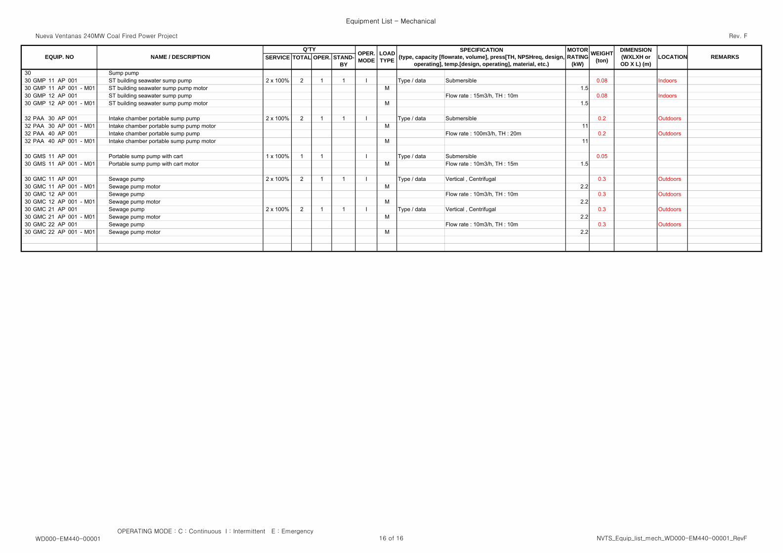
30 Sump pump30 GMP 11 AP 001 ST building seawater sump pump 2 x 100% 2 1 1 I Type / data Submersible 0.08 Indoors30 GMP 11 AP 001 - M01 ST building seawater sump pump motor M 1.530 GMP 12 AP 001 ST building seawater sump pump Flow rate : 15m3/h, TH : 10m 0.08 Indoors30 GMP 12 AP 001 - M01 ST building seawater sump pump motor M 1.5
32 PAA 30 AP 001 Intake chamber portable sump pump 2 x 100% 2 1 1 I Type / data Submersible 0.2 Outdoors32 PAA 30 AP 001 - M01 Intake chamber portable sump pump motor M 1132 PAA 40 AP 001 Intake chamber portable sump pump Flow rate : 100m3/h, TH : 20m 0.2 Outdoors32 PAA 40 AP 001 - M01 Intake chamber portable sump pump motor M 11
30 GMS 11 AP 001 Portable sump pump with cart 1 x 100% 1 1 I Type / data Submersible 0.0530 GMS 11 AP 001 - M01 Portable sump pump with cart motor M Flow rate : 10m3/h, TH : 15m 1.5
30 GMC 11 AP 001 Sewage pump 2 x 100% 2 1 1 I Type / data Vertical , Centrifugal 0.3 Outdoors30 GMC 11 AP 001 - M01 Sewage pump motor M 2.230 GMC 12 AP 001 Sewage pump Flow rate : 10m3/h, TH : 10m 0.3 Outdoors30 GMC 12 AP 001 - M01 Sewage pump motor M 2.230 GMC 21 AP 001 Sewage pump 2 x 100% 2 1 1 I Type / data Vertical , Centrifugal 0.3 Outdoors30 GMC 21 AP 001 - M01 Sewage pump motor M 2.230 GMC 22 AP 001 Sewage pump Flow rate : 10m3/h, TH : 10m 0.3 Outdoors30 GMC 22 AP 001 - M01 Sewage pump motor M 2.2
OPERATING MODE : C : Continuous I : Intermittent E : EmergencyWD000-EM440-00001 16 of 16 NVTS_Equip_list_mech_WD000-EM440-00001_RevF
APPRO APPRO
VAL VAL
2009/11/30
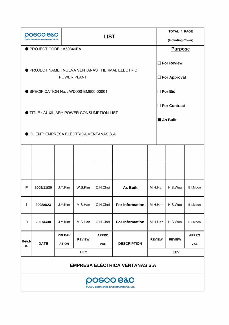
LISTTOTAL 4 PAGE
(Including Cover)
● PROJECT CODE : A50346EA
● PROJECT NAME : NUEVA VENTANAS THERMAL ELECTRIC
● TITLE : AUXILIARY POWER CONSUMPTION LIST
POWER PLANT
● SPECIFICATION No. : WD000-EM600-00001
● CLIENT: EMPRESA ELÉCTRICA VENTANAS S.A.
Purpose
□ For Review
□ For Approval
□ For Bid
□ For Contract
■ As Built
F M.H.HanJ.Y.Kim W.S.Kim
For Information1 J.Y.Kim M.S.Han C.H.Choi2008/9/23
DESCRIPTIONREVIEW
0 2007/6/30 For InformationJ.Y.Kim M.S.Han C.H.Choi M.H.Han
REVIEW
HEC EEV
EMPRESA ELÉCTRICA VENTANAS S.A
Rev.No. DATE
PREPAR
ATIONREVIEW
C.H.Choi As Built H.S.Woo B.I.Moon
M.H.Han H.S.Woo B.I.Moon
H.S.Woo B.I.Moon
Nueva Ventanas 240MW Coal Fired Power Project
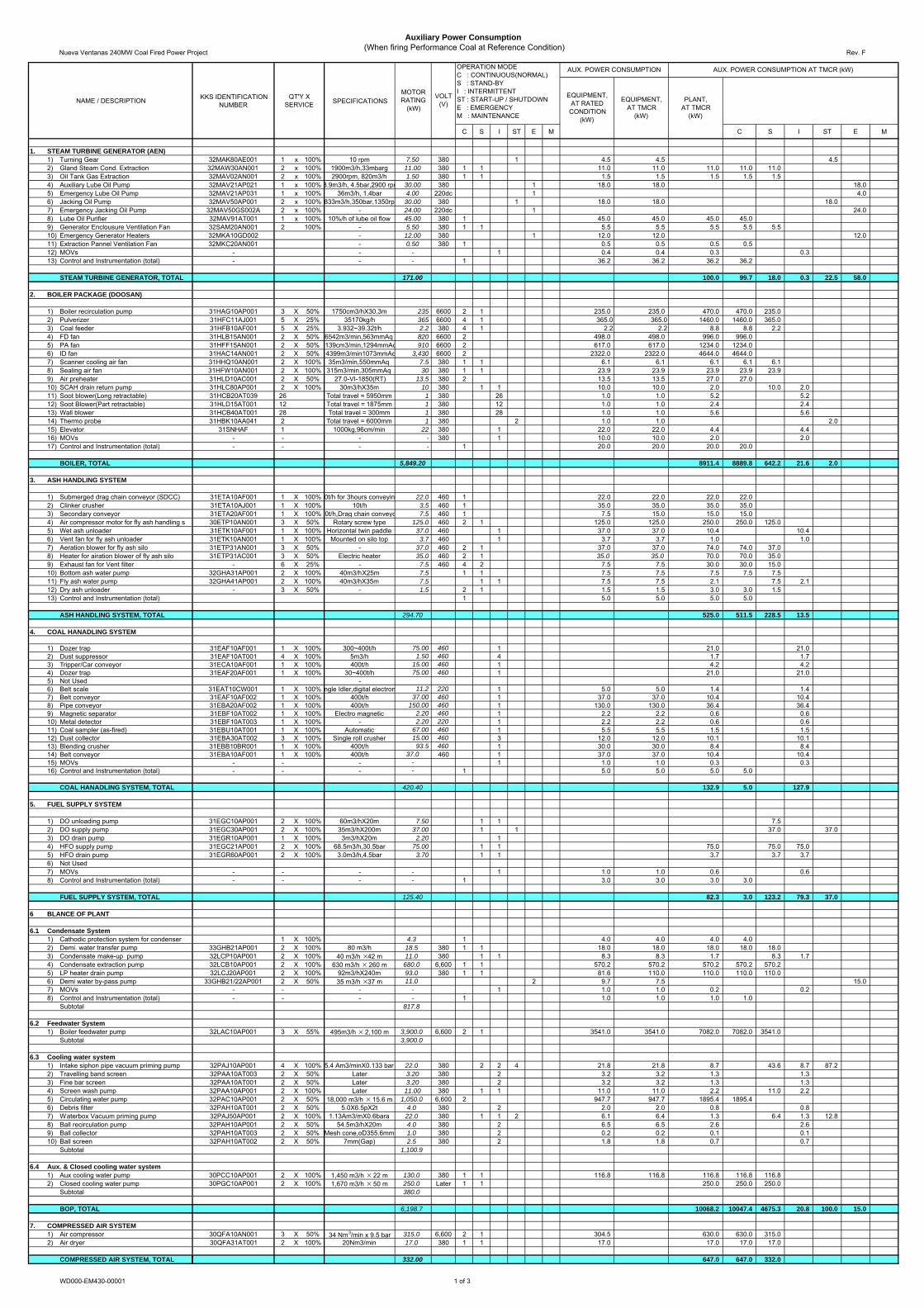
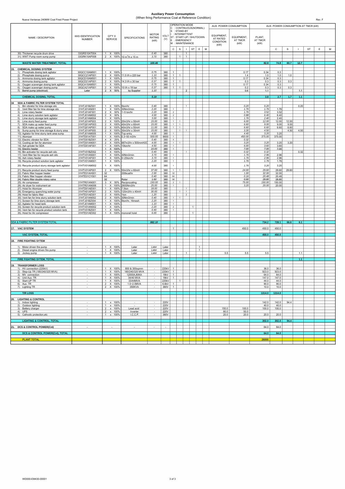
Auxiliary Power Consumption(When firing Performance Coal at Reference Condition)
Rev. F
KKS IDENTIFICATIONNUMBER SPECIFICATIONS
C S I ST E M C S I ST E M
1. STEAM TURBINE GENERATOR (AEN)1) Turning Gear 32MAK80AE001 1 x 100% 10 rpm 7.50 380 1 4.5 4.5 4.52) Gland Steam Cond. Extraction 32MAW30AN001 2 x 100% 1900m3/h,33mbarg 11.00 380 1 1 11.0 11.0 11.0 11.0 11.03) Oil Tank Gas Extraction 32MAV02AN001 2 x 100% 2900rpm, 820m3/h 1.50 380 1 1 1.5 1.5 1.5 1.5 1.54) Auxiliary Lube Oil Pump 32MAV21AP021 1 x 100% 8.9m3/h, 4.5bar,2900 rpm 30.00 380 1 18.0 18.0 18.05) Emergency Lube Oil Pump 32MAV21AP031 1 x 100% 36m3/h, 1.4bar 4.00 220dc 1 4.06) Jacking Oil Pump 32MAV50AP001 2 x 100% 833m3/h,350bar,1350rp 30.00 380 1 18.0 18.0 18.07) Emergency Jacking Oil Pump 32MAV50GS002A 2 x 100% - 24.00 220dc 1 24.08) Lube Oil Purifier 32MAV91AT001 1 x 100% 10%/h of lube oil flow 45.00 380 1 45.0 45.0 45.0 45.09) Generator Enclousure Ventilation Fan 32SAM20AN001 2 100% - 5.50 380 1 1 5.5 5.5 5.5 5.5 5.510) Emergency Generator Heaters 32MKA10GD002 - 12.00 380 1 12.0 12.0 12.011) Extraction Pannel Ventilation Fan 32MKC20AN001 - 0.50 380 1 0.5 0.5 0.5 0.512) MOVs - - - 1 0.4 0.4 0.3 0.313) Control and Instrumentation (total) - - - 1 36.2 36.2 36.2 36.2
STEAM TURBINE GENERATOR, TOTAL 171.00 100.0 99.7 18.0 0.3 22.5 58.0
2. BOILER PACKAGE (DOOSAN)
1) Boiler recirculation pump 31HAG10AP001 3 X 50% 1750cm3/hX30.3m 235 6600 2 1 235.0 235.0 470.0 470.0 235.02) Pulverizer 31HFC11AJ001 5 X 25% 35170kg/h 365 6600 4 1 365.0 365.0 1460.0 1460.0 365.03) Coal feeder 31HFB10AF001 5 X 25% 3.932~39.32t/h 2.2 380 4 1 2.2 2.2 8.8 8.8 2.24) FD fan 31HLB15AN001 2 X 50% 6542m3/min,563mmAq 820 6600 2 498.0 498.0 996.0 996.05) PA fan 31HFF15AN001 2 X 50% 3139cm3/min,1294mmAq 910 6600 2 617.0 617.0 1234.0 1234.06) ID fan 31HAC14AN001 2 X 50% 14399m3/min1073mmAq 3,430 6600 2 2322.0 2322.0 4644.0 4644.07) Scanner cooling air fan 31HHQ10AN001 2 X 100% 35m3/min,550mmAq 7.5 380 1 1 6.1 6.1 6.1 6.1 6.18) Sealing air fan 31HFW10AN001 2 X 100% 315m3/min,305mmAq 30 380 1 1 23.9 23.9 23.9 23.9 23.99) Air preheater 31HLD10AC001 2 X 50% 27.0-VI-1850(RT) 13.5 380 2 13.5 13.5 27.0 27.010) SCAH drain return pump 31HLC80AP001 2 X 100% 30m3/hX35m 10 380 1 1 10.0 10.0 2.0 10.0 2.011) Soot blower(Long retractable) 31HCB20AT039 26 Total travel = 5950mm 1 380 26 1.0 1.0 5.2 5.212) Soot Blower(Part retractable) 31HLD15AT001 12 Total travel = 1875mm 1 380 12 1.0 1.0 2.4 2.413) Wall blower 31HCB40AT001 28 Total travel = 300mm 1 380 28 1.0 1.0 5.6 5.614) Thermo probe 31HBK10AA041 2 Total travel = 6000mm 1 380 2 1.0 1.0 2.015) Elevator 31SNHAF 1 1000kg,96cm/min 22 380 1 22.0 22.0 4.4 4.416) MOVs - - - - 380 1 10.0 10.0 2.0 2.017) Control and Instrumentation (total) - - - - 1 20.0 20.0 20.0 20.0
BOILER, TOTAL 5,849.20 8911.4 8889.8 642.2 21.6 2.0
3. ASH HANDLING SYSTEM
1) Submerged drag chain conveyor (SDCC) 31ETA10AF001 1 X 100% 0t/h for 3hours conveyin 22.0 460 1 22.0 22.0 22.0 22.02) Clinker crusher 31ETA10AJ001 1 X 100% 10t/h 3.5 460 1 35.0 35.0 35.0 35.03) Secondary conveyor 31ETA20AF001 1 X 100% 0t/h,Drag chain conveyo 7.5 460 1 7.5 15.0 15.0 15.04) Air compressor motor for fly ash handling s 30ETP10AN001 3 X 50% Rotary screw type 125.0 460 2 1 125.0 125.0 250.0 250.0 125.05) Wet ash unloader 31ETK10AF001 1 X 100% Horizontal twin paddle 37.0 460 1 37.0 37.0 10.4 10.46) Vent fan for fly ash unloader 31ETK10AN001 1 X 100% Mounted on silo top 3.7 460 1 3.7 3.7 1.0 1.07) Aeration blower for fly ash silo 31ETP31AN001 3 X 50% - 37.0 460 2 1 37.0 37.0 74.0 74.0 37.08) Heater for airation blower of fly ash silo 31ETP31AC001 3 X 50% Electric heater 35.0 460 2 1 35.0 35.0 70.0 70.0 35.09) Exhaust fan for Vent filter - 6 X 25% - 7.5 460 4 2 7.5 7.5 30.0 30.0 15.010) Bottom ash water pump 32GHA31AP001 2 X 100% 40m3/hX25m 7.5 1 1 7.5 7.5 7.5 7.5 7.511) Fly ash water pump 32GHA41AP001 2 X 100% 40m3/hX35m 7.5 1 1 7.5 7.5 2.1 7.5 2.112) Dry ash unloader - 3 X 50% - 1.5 2 1 1.5 1.5 3.0 3.0 1.513) Control and Instrumentation (total) 1 5.0 5.0 5.0 5.0
ASH HANDLING SYSTEM, TOTAL 294.70 525.0 511.5 228.5 13.5
4. COAL HANADLING SYSTEM
1) Dozer trap 31EAF10AF001 1 X 100% 300~400t/h 75.00 460 1 21.0 21.02) Dust suppressor 31EAF10AT001 4 X 100% 5m3/h 1.50 460 4 1.7 1.73) Tripper/Car conveyor 31ECA10AF001 1 X 100% 400t/h 15.00 460 1 4.2 4.24) Dozer trap 31EAF20AF001 1 X 100% 30~400t/h 75.00 460 1 21.0 21.05) Not Used -6) Belt scale 31EAT10CW001 1 X 100% ngle Idler,digital electron 11.2 220 1 5.0 5.0 1.4 1.47) Belt conveyor 31EAF10AF002 1 X 100% 400t/h 37.00 460 1 37.0 37.0 10.4 10.48) Pipe conveyor 31EBA20AF002 1 X 100% 400t/h 150.00 460 1 130.0 130.0 36.4 36.49) Magnetic separator 31EBF10AT002 1 X 100% Electro magnetic 2.20 460 1 2.2 2.2 0.6 0.610) Metal detector 31EBF10AT003 1 X 100% - 2.20 220 1 2.2 2.2 0.6 0.611) Coal sampler (as-fired) 31EBU10AT001 1 X 100% Automatic 67.00 460 1 5.5 5.5 1.5 1.512) Dust collector 31EBA30AT002 3 X 100% Single roll crusher 15.00 460 3 12.0 12.0 10.1 10.113) Blending crusher 31EBB10BR001 1 X 100% 400t/h 93.5 460 1 30.0 30.0 8.4 8.414) Belt conveyor 31EBA10AF001 1 X 100% 400t/h 37.0 460 1 37.0 37.0 10.4 10.415) MOVs - - - - 1 1.0 1.0 0.3 0.316) Control and Instrumentation (total) - - - - 1 5.0 5.0 5.0 5.0
COAL HANADLING SYSTEM, TOTAL 420.40 132.9 5.0 127.9
5. FUEL SUPPLY SYSTEM
1) DO unloading pump 31EGC10AP001 2 X 100% 60m3/hX20m 7.50 1 1 7.52) DO supply pump 31EGC30AP001 2 X 100% 35m3/hX200m 37.00 1 1 37.0 37.03) DO drain pump 31EGR10AP001 1 X 100% 3m3/hX20m 2.20 14) HFO supply pump 31EGC21AP001 2 X 100% 68.5m3/h,30.5bar 75.00 1 1 75.0 75.0 75.05) HFO drain pump 31EGR60AP001 2 X 100% 3.0m3/h,4.5bar 3.70 1 1 3.7 3.7 3.76) Not Used7) MOVs - - - - 1 1.0 1.0 0.6 0.68) Control and Instrumentation (total) - - - - 1 3.0 3.0 3.0 3.0
FUEL SUPPLY SYSTEM, TOTAL 125.40 82.3 3.0 123.2 79.3 37.0
6 BLANCE OF PLANT
6.1 Condensate System1) Cathodic protection system for condenser 1 X 100% 4.3 1 4.0 4.0 4.0 4.02) Demi. water transfer pump 33GHB21AP001 2 X 100% 80 m3/h 18.5 380 1 1 18.0 18.0 18.0 18.0 18.03) Condensate make-up pump 32LCP10AP001 2 X 100% 40 m3/h ×42 m 11.0 380 1 1 8.3 8.3 1.7 8.3 1.74) Condensate extraction pump 32LCB10AP001 2 X 100% 630 m3/h × 260 m 680.0 6,600 1 1 570.2 570.2 570.2 570.2 570.25) LP heater drain pump 32LCJ20AP001 2 X 100% 92m3/hX240m 93.0 380 1 1 81.6 110.0 110.0 110.0 110.06) Demi water by-pass pump 33GHB21/22AP001 2 X 50% 35 m3/h ×37 m 11.0 2 9.7 7.5 15.07) MOVs - - - - 1 1.0 1.0 0.2 0.28) Control and Instrumentation (total) - - - - 1 1.0 1.0 1.0 1.0
Subtotal 817.8
6.2 Feedwater System1) Boiler feedwater pump 32LAC10AP001 3 X 55% 495m3/h × 2,100 m 3,900.0 6,600 2 1 3541.0 3541.0 7082.0 7082.0 3541.0
Subtotal 3,900.0
6.3 Cooling water system1) Intake siphon pipe vacuum priming pump 32PAJ10AP001 4 X 100% 5.4 Am3/minX0.133 bar 22.0 380 2 2 4 21.8 21.8 8.7 43.6 8.7 87.22) Travelling band screen 32PAA10AT003 2 X 50% Later 3.20 380 2 3.2 3.2 1.3 1.33) Fine bar screen 32PAA10AT001 2 X 50% Later 3.20 380 2 3.2 3.2 1.3 1.34) Screen wash pump 32PAA10AP001 2 X 100% Later 11.00 380 1 1 11.0 11.0 2.2 11.0 2.25) Circulating water pump 32PAC10AP001 2 X 50% 18,000 m3/h × 15.6 m 1,050.0 6,600 2 947.7 947.7 1895.4 1895.46) Debris filter 32PAH10AT001 2 X 50% 5.0X6.5pX2t 4.0 380 2 2.0 2.0 0.8 0.87) Waterbox Vacuum priming pump 32PAJ50AP001 2 X 100% 1.13Am3/mX0.6bara 22.0 380 1 1 2 6.1 6.4 1.3 6.4 1.3 12.88) Ball recirculation pump 32PAH10AP001 2 X 50% 54.5m3/hX20m 4.0 380 2 6.5 6.5 2.6 2.69) Ball collector 32PAH10AT003 2 X 50% Mesh cone,oD355.6mm 1.0 380 2 0.2 0.2 0.1 0.110) Ball screen 32PAH10AT002 2 X 50% 7mm(Gap) 2.5 380 2 1.8 1.8 0.7 0.7
Subtotal 1,100.9
6.4 Aux. & Closed cooling water system1) Aux cooling water pump 30PCC10AP001 2 X 100% 1,450 m3/h × 22 m 130.0 380 1 1 116.8 116.8 116.8 116.8 116.82) Closed cooling water pump 30PGC10AP001 2 X 100% 1,670 m3/h × 50 m 250.0 Later 1 1 250.0 250.0 250.0
Subtotal 380.0
BOP, TOTAL 6,198.7 10068.2 10047.4 4675.3 20.8 100.0 15.0
7. COMPRESSED AIR SYSTEM1) Air compressor 30QFA10AN001 3 X 50% 34 Nm3/min x 9.5 bar 315.0 6,600 2 1 304.5 630.0 630.0 315.02) Air dryer 30QFA31AT001 2 X 100% 20Nm3/min 17.0 380 1 1 17.0 17.0 17.0 17.0
COMPRESSED AIR SYSTEM, TOTAL 332.00 647.0 647.0 332.0
AUX. POWER CONSUMPTION AT TMCR (kW)
PLANT,AT TMCR
(kW)
QT'Y XSERVICENAME / DESCRIPTION
VOLT(V)
OPERATION MODEC : CONTINUOUS(NORMAL)S : STAND-BYI : INTERMITTENTST : START-UP / SHUTDOWNE : EMERGENCYM : MAINTENANCE
MOTORRATING
(kW)
AUX. POWER CONSUMPTION
EQUIPMENT,AT RATED
CONDITION(kW)
EQUIPMENT,AT TMCR
(kW)
WD000-EM430-00001 1 of 3
Nueva Ventanas 240MW Coal Fired Power Project
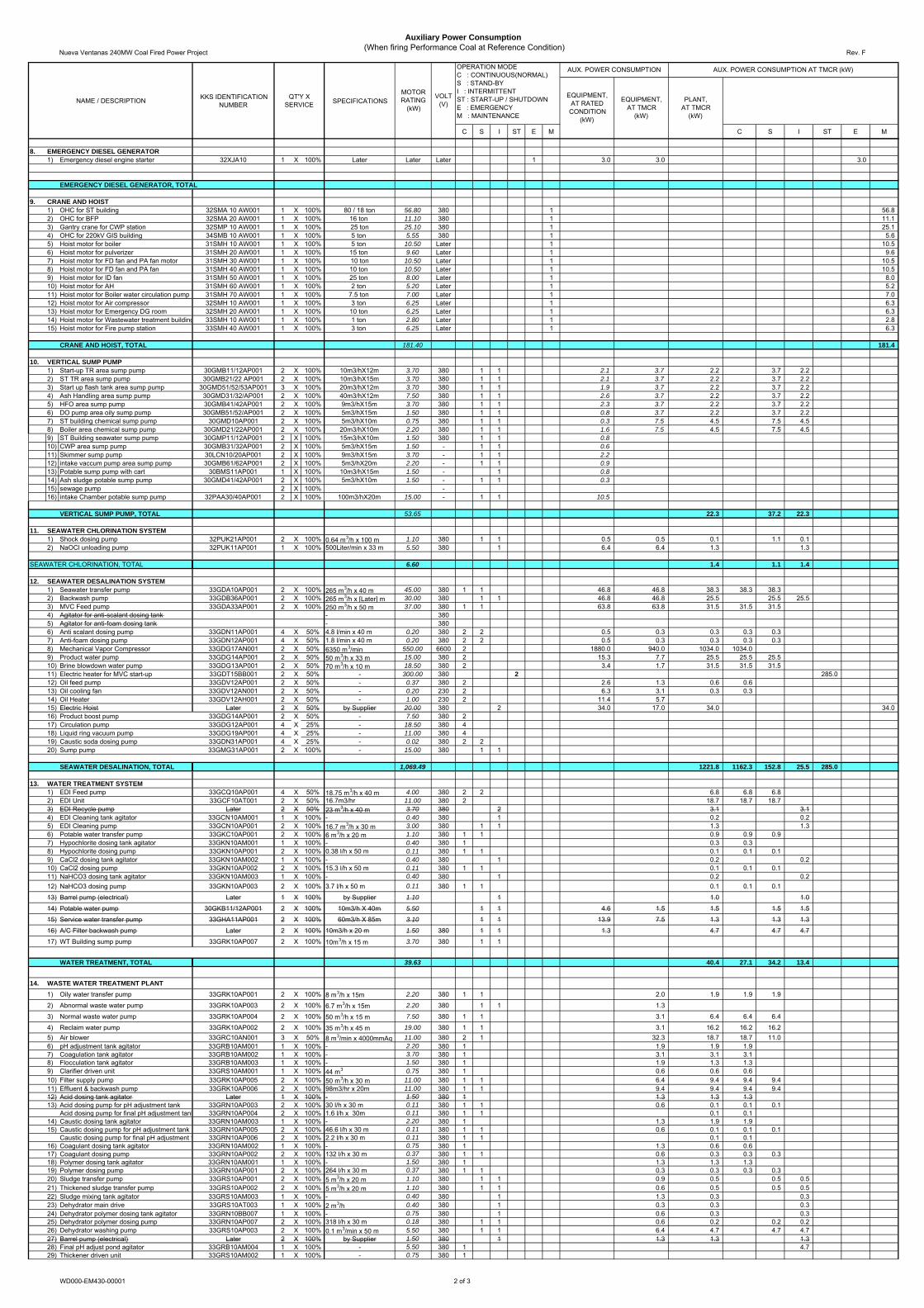
Auxiliary Power Consumption(When firing Performance Coal at Reference Condition)
Rev. F
KKS IDENTIFICATIONNUMBER SPECIFICATIONS
C S I ST E M C S I ST E M
AUX. POWER CONSUMPTION AT TMCR (kW)
PLANT,AT TMCR
(kW)
QT'Y XSERVICENAME / DESCRIPTION
VOLT(V)
OPERATION MODEC : CONTINUOUS(NORMAL)S : STAND-BYI : INTERMITTENTST : START-UP / SHUTDOWNE : EMERGENCYM : MAINTENANCE
MOTORRATING
(kW)
AUX. POWER CONSUMPTION
EQUIPMENT,AT RATED
CONDITION(kW)
EQUIPMENT,AT TMCR
(kW)
8. EMERGENCY DIESEL GENERATOR1) Emergency diesel engine starter 32XJA10 1 X 100% Later Later Later 1 3.0 3.0 3.0
EMERGENCY DIESEL GENERATOR, TOTAL
9. CRANE AND HOIST1) OHC for ST building 32SMA 10 AW001 1 X 100% 80 / 18 ton 56.80 380 1 56.82) OHC for BFP 32SMA 20 AW001 1 X 100% 16 ton 11.10 380 1 11.13) Gantry crane for CWP station 32SMP 10 AW001 1 X 100% 25 ton 25.10 380 1 25.14) OHC for 220kV GIS building 34SMB 10 AW001 1 X 100% 5 ton 5.55 380 1 5.65) Hoist motor for boiler 31SMH 10 AW001 1 X 100% 5 ton 10.50 Later 1 10.56) Hoist motor for pulverizer 31SMH 20 AW001 1 X 100% 15 ton 9.60 Later 1 9.67) Hoist motor for FD fan and PA fan motor 31SMH 30 AW001 1 X 100% 10 ton 10.50 Later 1 10.58) Hoist motor for FD fan and PA fan 31SMH 40 AW001 1 X 100% 10 ton 10.50 Later 1 10.59) Hoist motor for ID fan 31SMH 50 AW001 1 X 100% 25 ton 8.00 Later 1 8.010) Hoist motor for AH 31SMH 60 AW001 1 X 100% 2 ton 5.20 Later 1 5.211) Hoist motor for Boiler water circulation pump 31SMH 70 AW001 1 X 100% 7.5 ton 7.00 Later 1 7.012) Hoist motor for Air compressor 32SMH 10 AW001 1 X 100% 3 ton 6.25 Later 1 6.313) Hoist motor for Emergency DG room 32SMH 20 AW001 1 X 100% 10 ton 6.25 Later 1 6.314) Hoist motor for Wastewater treatment building 33SMH 10 AW001 1 X 100% 1 ton 2.80 Later 1 2.815) Hoist motor for Fire pump station 33SMH 40 AW001 1 X 100% 3 ton 6.25 Later 1 6.3
CRANE AND HOIST, TOTAL 181.40 181.4
10. VERTICAL SUMP PUMP1) Start-up TR area sump pump 30GMB11/12AP001 2 X 100% 10m3/hX12m 3.70 380 1 1 2.1 3.7 2.2 3.7 2.22) ST TR area sump pump 30GMB21/22 AP001 2 X 100% 10m3/hX15m 3.70 380 1 1 2.1 3.7 2.2 3.7 2.23) Start up flash tank area sump pump 30GMD51/52/53AP001 3 X 100% 20m3/hX12m 3.70 380 1 1 1.9 3.7 2.2 3.7 2.24) Ash Handling area sump pump 30GMD31/32/AP001 2 X 100% 40m3/hX12m 7.50 380 1 1 2.6 3.7 2.2 3.7 2.25) HFO area sump pump 30GMB41/42AP001 2 X 100% 9m3/hX15m 3.70 380 1 1 2.3 3.7 2.2 3.7 2.26) DO pump area oily sump pump 30GMB51/52/AP001 2 X 100% 5m3/hX15m 1.50 380 1 1 0.8 3.7 2.2 3.7 2.27) ST building chemical sump pump 30GMD10AP001 2 X 100% 5m3/hX10m 0.75 380 1 1 0.3 7.5 4.5 7.5 4.58) Boiler area chemical sump pump 30GMD21/22AP001 2 X 100% 20m3/hX10m 2.20 380 1 1 1.6 7.5 4.5 7.5 4.59) ST Building seawater sump pump 30GMP11/12AP001 2 X 100% 15m3/hX10m 1.50 380 1 1 0.810) CWP area sump pump 30GMB31/32AP001 2 X 100% 5m3/hX15m 1.50 - 1 1 0.611) Skimmer sump pump 30LCN10/20AP001 2 X 100% 9m3/hX15m 3.70 - 1 1 2.212) intake vaccum pump area sump pump 30GMB61/62AP001 2 X 100% 5m3/hX20m 2.20 - 1 1 0.913) Potable sump pump with cart 30BMS11AP001 1 X 100% 10m3/hX15m 1.50 - 1 0.814) Ash sludge potable sump pump 30GMD41/42AP001 2 X 100% 5m3/hX10m 1.50 - 1 1 0.315) sewage pump 2 X 100% -16) intake Chamber potable sump pump 32PAA30/40AP001 2 X 100% 100m3/hX20m 15.00 - 1 1 10.5
VERTICAL SUMP PUMP, TOTAL 53.65 22.3 37.2 22.3
11. SEAWATER CHLORINATION SYSTEM1) Shock dosing pump 32PUK21AP001 2 X 100% 0.64 m3/h x 100 m 1.10 380 1 1 0.5 0.5 0.1 1.1 0.12) NaOCl unloading pump 32PUK11AP001 1 X 100% 500Liter/min x 33 m 5.50 380 1 6.4 6.4 1.3 1.3
SEAWATER CHLORINATION, TOTAL 6.60 1.4 1.1 1.4
12. SEAWATER DESALINATION SYSTEM1) Seawater transfer pump 33GDA10AP001 2 X 100% 265 m3/h x 40 m 45.00 380 1 1 46.8 46.8 38.3 38.3 38.32) Backwash pump 33GDB36AP001 2 X 100% 265 m3/h x [Later] m 30.00 380 1 1 46.8 46.8 25.5 25.5 25.53) MVC Feed pump 33GDA33AP001 2 X 100% 250 m3/h x 50 m 37.00 380 1 1 63.8 63.8 31.5 31.5 31.54) Agitator for anti-scalant dosing tank - 3805) Agitator for anti-foam dosing tank - 3806) Anti scalant dosing pump 33GDN11AP001 4 X 50% 4.8 l/min x 40 m 0.20 380 2 2 0.5 0.3 0.3 0.3 0.37) Anti-foam dosing pump 33GDN12AP001 4 X 50% 1.8 l/min x 40 m 0.20 380 2 2 0.5 0.3 0.3 0.3 0.38) Mechanical Vapor Compressor 33GDG17AN001 2 X 50% 6350 m3/min 550.00 6600 2 1880.0 940.0 1034.0 1034.09) Product water pump 33GDG14AP001 2 X 50% 50 m3/h x 33 m 15.00 380 2 15.3 7.7 25.5 25.5 25.510) Brine blowdown water pump 33GDG13AP001 2 X 50% 70 m3/h x 10 m 18.50 380 2 3.4 1.7 31.5 31.5 31.511) Electric heater for MVC start-up 33GDT15BB001 2 X 50% - 300.00 380 2 285.012) Oil feed pump 33GDV12AP001 2 X 50% - 0.37 380 2 2.6 1.3 0.6 0.613) Oil cooling fan 33GDV12AN001 2 X 50% - 0.20 230 2 6.3 3.1 0.3 0.314) Oil Heater 33GDV12AH001 2 X 50% - 1.00 230 2 11.4 5.715) Electric Hoist Later 2 X 50% by Supplier 20.00 380 2 34.0 17.0 34.0 34.016) Product boost pump 33GDG14AP001 2 X 50% - 7.50 380 217) Circulation pump 33GDG12AP001 4 X 25% - 18.50 380 418) Liquid ring vacuum pump 33GDG19AP001 4 X 25% - 11.00 380 419) Caustic soda dosing pump 33GDN31AP001 4 X 25% - 0.02 380 2 220) Sump pump 33GMG31AP001 2 X 100% - 15.00 380 1 1
SEAWATER DESALINATION, TOTAL 1,069.49 1221.8 1162.3 152.8 25.5 285.0
13. WATER TREATMENT SYSTEM1) EDI Feed pump 33GCQ10AP001 4 X 50% 18.75 m3/h x 40 m 4.00 380 2 2 6.8 6.8 6.82) EDI Unit 33GCF10AT001 2 X 50% 16.7m3/hr 11.00 380 2 18.7 18.7 18.73) EDI Recycle pump Later 2 X 50% 23 m3/h x 40 m 3.70 380 2 3.1 3.14) EDI Cleaning tank agitator 33GCN10AM001 1 X 100% - 0.40 380 1 0.2 0.25) EDI Cleaning pump 33GCN10AP001 2 X 100% 16.7 m3/h x 30 m 3.00 380 1 1 1.3 1.36) Potable water transfer pump 33GKC10AP001 2 X 100% 6 m3/h x 20 m 1.10 380 1 1 0.9 0.9 0.97) Hypochlorite dosing tank agitator 33GKN10AM001 1 X 100% - 0.40 380 1 0.3 0.38) Hypochlorite dosing pump 33GKN10AP001 2 X 100% 0.38 l/h x 50 m 0.11 380 1 1 0.1 0.1 0.19) CaCl2 dosing tank agitator 33GKN10AM002 1 X 100% - 0.40 380 1 0.2 0.210) CaCl2 dosing pump 33GKN10AP002 2 X 100% 15.3 l/h x 50 m 0.11 380 1 1 0.1 0.1 0.111) NaHCO3 dosing tank agitator 33GKN10AM003 1 X 100% - 0.40 380 1 0.2 0.212) NaHCO3 dosing pump 33GKN10AP003 2 X 100% 3.7 l/h x 50 m 0.11 380 1 1 0.1 0.1 0.1
13) Barrel pump (electrical) Later 1 X 100% by Supplier 1.10 1 1.0 1.0
14) Potable water pump 30GKB11/12AP001 2 X 100% 10m3/h X 40m 5.50 1 1 4.6 1.5 1.5 1.5 1.5
15) Service water transfer pump 33GHA11AP001 2 X 100% 60m3/h X 85m 3.10 1 1 13.9 7.5 1.3 1.3 1.3
16) A/C Filter backwash pump Later 2 X 100% 10m3/h x 20 m 1.50 380 1 1 1.3 4.7 4.7 4.7
17) WT Building sump pump 33GRK10AP007 2 X 100% 10m3/h x 15 m 3.70 380 1 1
WATER TREATMENT, TOTAL 39.63 40.4 27.1 34.2 13.4
14. WASTE WATER TREATMENT PLANT1) Oily water transfer pump 33GRK10AP001 2 X 100% 8 m3/h x 15m 2.20 380 1 1 2.0 1.9 1.9 1.9
2) Abnormal waste water pump 33GRK10AP003 2 X 100% 6.7 m3/h x 15m 2.20 380 1 1 1.3
3) Normal waste water pump 33GRK10AP004 2 X 100% 50 m3/h x 15 m 7.50 380 1 1 3.1 6.4 6.4 6.4
4) Reclaim water pump 33GRK10AP002 2 X 100% 35 m3/h x 45 m 19.00 380 1 1 3.1 16.2 16.2 16.25) Air blower 33GRC10AN001 3 X 50% 8 m3/min x 4000mmAq 11.00 380 2 1 32.3 18.7 18.7 11.06) pH adjustment tank agitator 33GRB10AM001 1 X 100% - 2.20 380 1 1.9 1.9 1.97) Coagulation tank agitator 33GRB10AM002 1 X 100% - 3.70 380 1 3.1 3.1 3.18) Flocculation tank agitator 33GRB10AM003 1 X 100% - 1.50 380 1 1.9 1.3 1.39) Clarifier driven unit 33GRS10AM001 1 X 100% 44 m3 0.75 380 1 0.6 0.6 0.610) Filter supply pump 33GRK10AP005 2 X 100% 50 m3/h x 30 m 11.00 380 1 1 6.4 9.4 9.4 9.411) Effluent & backwash pump 33GRK10AP006 2 X 100% 98m3/hr x 20m 11.00 380 1 1 9.4 9.4 9.4 9.412) Acid dosing tank agitator Later 1 X 100% - 1.50 380 1 1.3 1.3 1.313) Acid dosing pump for pH adjustment tank 33GRN10AP003 2 X 100% 30 l/h x 30 m 0.11 380 1 1 0.6 0.1 0.1 0.1
Acid dosing pump for final pH adjustment tank 33GRN10AP004 2 X 100% 1.6 l/h x 30m 0.11 380 1 1 0.1 0.114) Caustic dosing tank agitator 33GRN10AM003 1 X 100% - 2.20 380 1 1.3 1.9 1.915) Caustic dosing pump for pH adjustment tank 33GRN10AP005 2 X 100% 46.6 l/h x 30 m 0.11 380 1 1 0.6 0.1 0.1 0.1
Caustic dosing pump for final pH adjustment t 33GRN10AP006 2 X 100% 2.2 l/h x 30 m 0.11 380 1 1 0.1 0.116) Coagulant dosing tank agitator 33GRN10AM002 1 X 100% - 0.75 380 1 1.3 0.6 0.617) Coagulant dosing pump 33GRN10AP002 2 X 100% 132 l/h x 30 m 0.37 380 1 1 0.6 0.3 0.3 0.318) Polymer dosing tank agitator 33GRN10AM001 1 X 100% - 1.50 380 1 1.3 1.3 1.319) Polymer dosing pump 33GRN10AP001 2 X 100% 264 l/h x 30 m 0.37 380 1 1 0.3 0.3 0.3 0.320) Sludge transfer pump 33GRS10AP001 2 X 100% 5 m3/h x 20 m 1.10 380 1 1 0.9 0.5 0.5 0.521) Thickened sludge transfer pump 33GRS10AP002 2 X 100% 5 m3/h x 20 m 1.10 380 1 1 0.6 0.5 0.5 0.522) Sludge mixing tank agitator 33GRS10AM003 1 X 100% - 0.40 380 1 1.3 0.3 0.323) Dehydrator main drive 33GRS10AT003 1 X 100% 2 m3/h 0.40 380 1 0.3 0.3 0.324) Dehydrator polymer dosing tank agitator 33GRN10BB007 1 X 100% - 0.75 380 1 0.6 0.3 0.325) Dehydrator polymer dosing pump 33GRN10AP007 2 X 100% 318 l/h x 30 m 0.18 380 1 1 0.6 0.2 0.2 0.226) Dehydrator washing pump 33GRS10AP003 2 X 100% 0.1 m3/min x 50 m 5.50 380 1 1 6.4 4.7 4.7 4.727) Barrel pump (electrical) Later 2 X 100% by Supplier 1.50 380 1 1.3 1.3 1.328) Final pH adjust pond agitator 33GRB10AM004 1 X 100% - 5.50 380 1 4.729) Thickener driven unit 33GRS10AM002 1 X 100% - 0.75 380 1
WD000-EM430-00001 2 of 3
Nueva Ventanas 240MW Coal Fired Power Project
Auxiliary Power Consumption(When firing Performance Coal at Reference Condition)
Rev. F
KKS IDENTIFICATIONNUMBER SPECIFICATIONS
C S I ST E M C S I ST E M
AUX. POWER CONSUMPTION AT TMCR (kW)
PLANT,AT TMCR
(kW)
QT'Y XSERVICENAME / DESCRIPTION
VOLT(V)
OPERATION MODEC : CONTINUOUS(NORMAL)S : STAND-BYI : INTERMITTENTST : START-UP / SHUTDOWNE : EMERGENCYM : MAINTENANCE
MOTORRATING
(kW)
AUX. POWER CONSUMPTION
EQUIPMENT,AT RATED
CONDITION(kW)
EQUIPMENT,AT TMCR
(kW)
30) Thickener recycle drum drive 33GRS10AT004 1 X 100% - 0.40 380 131) WWT Pump room sump pump 33GRK10AP008 2 X 100% 10 m3/h x 15 m 3.70 380 1 1
WASTE WATER TREATMENT, TOTAL 100.46 82.8 74.8 60.7 12.7
15. CHEMICAL DOSING SYSTEM1) Phosphate dosing tank agitator 30QCC10AM001 1 X 100% - 0.75 380 1 0.17 0.34 0.32) Phosphate dosing pum p 30QCC21AP001 2 X 100% 11.5 l/h x 220 bar 1.10 380 1 1 1.4 1.0 1.0 1.03) Ammonia dosing tank agitator 30QCD10AM001 1 X 100% - 0.75 380 1 0.17 0.34 0.34) Ammonia dosing pump 30QCD21AP001 2 X 100% 14.3 l/h x 30 bar 0.37 380 1 1 0.3 0.3 0.3 0.35) Oxygen scavenger dosing tank agitator 30QCA10AM001 1 X 100% - 0.75 380 1 0.17 0.34 0.36) Oxygen scavenger dosing pump 30QCA21AP001 2 X 100% 10 l/h x 18 bar 0.37 380 1 1 0.2 0.3 0.3 0.37) Barrel pump (electrical) Later 2 X 50% by Supplier 1.10 2 0.6 1.1 1.1
CHEMICAL DOSING, TOTAL 5.19 3.8 2.7 1.7 1.1
16 SDA & FABRIC FILTER SYSTEM TOTAL1) Bin vibrator for lime storage silo 31HTJ01BZ001 1 X 100% 5ton/hr 0.40 380 1 0.20 0.20 0.202) Vent filter fan for lime storage silo 31HTJ01AN001 1 X 100% 30Nm3/min 2.20 380 1 1.76 1.76 1.763) Lime rotary feeder 31HTJ01AF001 2 X 50% 1~5 ton/hr 2.20 380 2 1.76 3.52 3.524) Lime slurry solution tank agitator 31HTJ01AM002 2 X 50% - 4.00 380 2 0.88 6.40 6.405) Lime slurry storage tank agitator 31HTJ01AM004 1 X 100% - 3.00 380 1 1.76 2.40 2.406) Lime slurry feed pump 31HTJ01AP003 2 X 100% 20m3/hr x 50mH 15.00 380 1 1 6.00 12.00 12.00 12.007) SDA make up water feed pump 31HTQ01AP003 2 X 100% 40m3/hr x 60mH 15.00 380 1 1 6.60 9.00 9.00 9.008) SDA make up water pump 31HTQ01AP001 2 X 100% 40m3/hr x 50mH 11.00 380 1 1 6.60 6.60 6.60 6.609) Sump pump for lime storage & slurry area 31HTJ01AP005 2 X 100% 30m3/hr x 30mH 15.00 380 1 1 3.30 4.50 4.50 4.5010) Agitator for lime slurry tank area sump 31HTJ01AM005 1 X 100% Top entry 4.00 380 1 4.40 3.20 3.2011) Atomizer 31HTD01AT001 1 X 100% 0.3~50 m3/hr 500.00 6600 1 450.00 375.00 375.0012) Electric vibrator for SDA 31HTD01BZ001 4 X 25% - 0.40 380 4 0.3213) Cooling air fan for atomizer 31HTD01AN001 2 X 100% 887m3/hr x 500mmH2O 4.00 380 1 1 3.20 3.20 3.20 3.2014) Ash grinder for SDA 31HTD01AF001 1 X 100% 10ton/hr 4.50 380 1 6.00 3.60 3.6015) Electric heater 1 X 100% - 10.00 380 1 7.00 7.00 7.0016) Bin activator for recycle ash silo 31HTV01BZ002 1 X 100% - 0.40 380 1 0.32 0.32 0.3217) Vent filter fan for recycle ash silo 31HTV01AN001 1 X 100% 30Nm3/min 3.70 380 1 1.76 2.96 2.9618) Ash rotary feeder 31HTV01AF001 1 X 100% 5~25ton/hr 3.70 380 1 1.76 2.96 2.9619) Recycle product solution tank agitator 31HTV01AM001 1 X 100% - 2.20 380 1 1.76 1.76 1.76
20) Recycle product slurry storage tank agitator 31HTV01AM002 1 X 100% - 4.00 380 1 1.76 3.20 3.20
21) Recycle product slurry feed pump 31HTV01AP001 2 X 100% 50m3/hr x 60mH 37.00 380 1 1 24.00 29.60 29.60 29.6022) Fabric filter hopper heater 31HTE01AH001 32 200kcal/hr 2.00 380 32 1.00 32.00 32.0023) Fabric filter hopper vibrator 31HTE01CY001 64 - 0.40 380 64 0.16 20.48 20.4824) Fabric filter double rotary valve 32 Rotor 1.50 380 32 0.90 28.80 28.8025) Air compressor 31HTR01AN001 3 X 50% Reciprocating 150.00 380 2 1 75.00 150.00 150.0026) Air dryer for instrument air 31HTR01AN006 1 X 100% 2600Nm3/hr 25.00 380 1 3.20 20.00 20.0027) Hoist for Atomizer 31HTD01AE001 1 X 100% 7.5ton 18.00 380 128) Emergency quenching water pump 31HTH01AP001 2 X 100% 120m3/hr x 40mH 30.00 380 1 129) Hoist for fabric filter 31HTE01AE001 2 X 100% 1ton 1.20 380 230) Vent fan for lime slurry solution tank 31HTJ01AN002 2 X 100% 30Nm3/min 0.40 380 1 131) Screen for lime slurry storage tank 31HTJ01BZ004 1 X 100% 5ton/hr, 16mesh 2.20 380 132) Agitator for head tank 31HTJ01AM001 1 X 100% - 1.10 380 133) Screen for recycle product solution tank 31HTV01AN002 1 X 100% - 2.20 380 2 134) Vent fan for recycle product solution tank 31HTV01BZ001 1 X 100% - 0.40 380 135) Hoist for Air compressor 31HTE01AE002 1 X 100% monorail hoist 6.00 380 1
SDA & FABRIC FILTER SYSTEM TOTAL 882.10 734.2 728.1 66.6 6.1
17. VAC SYSTEM 1 450.0 450.0 450.0
VAC SYSTEM, TOTAL 450.0 450.0
18. FIRE FIGHTING SYTEM
1) Motor driven fire pump - 1 X 100% Later Later Later 12) Diesel engine driven fire pump - 1 X 100% Later Later Later 13) Jockey pump - 1 X 100% Later Later Later 1 5.5 5.5 5.5 1.1
FIRE FIGHTING SYTEM, TOTAL 1.1
19. TRANSFORMER LOSS1) HV connection (220kV) - 1 X 100% 800 & 300sqmm - 220kV 1 36.0 36.02) Step-Up TR (180/240/320 MVA) - 1 X 100% 180/240/320 MVA - 220kV 1 923.0 923.03) MV connection - 1 X 100% 12000A,80KA - 18kV 1 64.0 64.04) Unit Aux. TR - 1 X 100% 34/40 MVA - 18kV 1 147.0 147.05) Start-UP TR - 1 X 100% 33/44MVA - 220kV 1 44.0 44.06) Aux. TR - 2 X 100% 1.0~2.5MVA - 6.6kV 1 90.0 90.07) Lighting TR - 2 X 100% 350KVA - 380V 1 10.0 10.0
T/R LOSS 1314.0 1314.0
20. LIGHTING & CONTROL1) Indoor lighting - 1 x 100% - - 220V 142.0 142.0 94.42) Outdoor lighting - 1 x 100% - - 220V 40.0 40.03) Battery charger - 2 x 100% Lead acid - 220V 150.0 100.0 100.0 100.04) UPS - 2 x 100% Inverter - 220V 80.0 50.05) Cathodic protection,etc - 1 x 100% I.C.C.P. - 380V 20.0 20.0 20.0 20.0
LIGHTING & CONTROL, TOTAL 302.0 302.0 94.4
21. DCS & CONTROL POWER(CnI) - - - - - 64.0 64.0
DCS & CONTROL POWER(CnI), TOTAL 64.0 64.0
PLANT TOTAL 26000
WD000-EM430-00001 3 of 3
SPECIFICATION TOTAL 226 PAGE (Including Cover)
● PROJECT CODE : A50346EA ● PROJECT NAME : NUEVA VENTANAS 240MW COAL FIRED
POWER PROJECT ● DOCUMENT No. : WD000-EM241-00004
● TITLE : TECHNICAL DESCRIPTION – PLANT OVERALL
(MECHANICAL) ● OWNER: EMPRESA ELÉCTRICA VENTANAS S.A.
Purpose □ For Review
□ For Approval
□ For Construction
□ For Bid
□ For Information
■ AS BUILT
F 2009/11/30 J.Y.Kim W.S. Kim C.H.Choi AS BUILT J.S. Lee M.H.Han B.I. Moon
2 2009/2/20 J.Y.Kim W.S. Kim C.H.Choi For Construction J.S. Lee M.H.Han B.I. Moon
1 2008/12/31 J.Y.Kim M.S.Han C.H.Choi For Construction J.S. Lee M.H.Han B.I. Moon
0 2008/7/31 J.Y.Kim M.S.Han C.H.Choi For Construction J.S. Lee H.S.Woo B.I. Moon
A 2008/5/19 J.Y.Kim M.S.Han C.H.Choi For Review J.S. Lee H.S.Woo B.I. Moon
PREP REVIEW APPR REVIEW REVIEW APPR Rev.No. DATE
HEC DESCRIPTION
POSCO E&C
Owner:
EMPRESA ELÉCTRICA VENTANAS S.A. Contractor:
NUEVA VENTANAS 240MW COAL FIRED POWER PROJECT Technical Description – Plant Overall (Mechanical) Rev. F
WD000-EM241-00003 i
CONTENTS
1. GENERAL ........................................................................................................................................ 1
1.1 Introduction ................................................................................................................................. 1
1.2 Project Description (1.1) ........................................................................................................... 1
1.3 Description of Main Equipment and Systems (2.4) .............................................................. 2
1.4 Contractor’s Terminal Points (2.3)........................................................................................... 6
2. FACILITY DESIGN BASES (3) ........................................................................................................ 8
2.1 Site Information .......................................................................................................................... 8
2.2 Design Codes and Standards (3.4)......................................................................................... 9
2.3 Facility Design Bases (2.4.4) ................................................................................................. 11
2.4 Quantity of Starts Over 30 years Design Life (3.5)..................................................................... 12
2.5 Frequency Limits (3.6) ............................................................................................................ 13
2.6 Voltage Limits (3.7).................................................................................................................. 13
2.7 Reactive Power (3.8) ............................................................................................................... 13
2.8 Fuel and Lime Specification (3.9) .......................................................................................... 14
2.9 Mechanical Criteria (4) ............................................................................................................ 24
2.10 Noise Criteria .......................................................................................................................... 31
3. PULVERIZED COAL FIRED BOILER (4.3) ................................................................................... 33
3.1 Function..................................................................................................................................... 33
3.2 Design Bases............................................................................................................................ 33
3.3 Description ................................................................................................................................ 37
4. STEAM TURBINE AND GENERATOR (4.6) ................................................................................. 72
4.1 Function..................................................................................................................................... 72
4.2 Design Bases............................................................................................................................ 72
4.3 Description ................................................................................................................................ 73
5. MAIN AND REHEAT STEAM SYSTEM......................................................................................... 97
5.1 Function..................................................................................................................................... 97
5.2 Design Bases............................................................................................................................ 97
5.3 Description ................................................................................................................................ 97
6. AUXILIARY STEAM SYSTEM (4.29) ........................................................................................... 102
6.1 Function................................................................................................................................... 102
6.2 Design Bases.......................................................................................................................... 102
6.3 Description .............................................................................................................................. 103
NUEVA VENTANAS 240MW COAL FIRED POWER PROJECT Technical Description – Plant Overall (Mechanical) Rev. F
WD000-EM241-00003
ii
7. FEEDWATER SYSTEM (4.10)..................................................................................................... 105
7.1 Function................................................................................................................................... 105
7.2 Design Bases.......................................................................................................................... 105
7.3 Description .............................................................................................................................. 106
8. FEEDWATER HEATING SYSTEM (4.7)...................................................................................... 110
8.1 Function................................................................................................................................... 110
8.2 Design Bases.......................................................................................................................... 110
8.3 Description .............................................................................................................................. 115
9. CONDENSER AND CONDENSATE SYSTEM (4.7, 4.11) .......................................................... 123
9.1 Function................................................................................................................................... 132
9.2 Design Bases.......................................................................................................................... 132
9.3 Description .............................................................................................................................. 132
10. COOLING WATER SYSTEM (4.11) ......................................................................................... 132
10.1 Function ................................................................................................................................. 132
10.2 Design Bases........................................................................................................................ 132
10.3 Description ............................................................................................................................ 134
11. CLOSED COOLING WATER SYSTEM (4.12) ......................................................................... 141
11.1 Function ................................................................................................................................. 141
11.2 Design Bases........................................................................................................................ 142
11.3 Description ............................................................................................................................ 143
12. FUEL OIL SUPPLY SYSTEM (4.20) ........................................................................................ 148
12.1 Function ................................................................................................................................. 148
12.2 Design Bases........................................................................................................................ 148
12.3 Description ............................................................................................................................ 150
13. COAL HANDLING SYSTEM (4.18) .......................................................................................... 155
13.1 Function ................................................................................................................................. 155
13.2 Design Bases........................................................................................................................ 155
13.3 Description ............................................................................................................................ 156
14. ASH HANDLING SYSTEM (4.19)............................................................................................. 160
14.1 Function ................................................................................................................................. 160
14.2 Design Bases........................................................................................................................ 160
14.3 Description ............................................................................................................................ 162
15. SERVICE AND INSTRUMENT AIR SYSTEM (4.14) ............................................................... 168
NUEVA VENTANAS 240MW COAL FIRED POWER PROJECT Technical Description – Plant Overall (Mechanical) Rev. F
WD000-EM241-00003
iii
15.1 Function ................................................................................................................................. 168
15.2 Design Bases........................................................................................................................ 168
15.3 Description ............................................................................................................................ 169
16. DRAINAGE SYSTEM (4.28)..................................................................................................... 172
16.1 Function ................................................................................................................................. 172
16.2 Design Bases........................................................................................................................ 172
16.3 Description ............................................................................................................................ 174
17. SELECTIVE CATALYTIC REDUCTION (SCR) SYSTEM – OPTIONAL (4.4) ......................... 178
17.1 Function ................................................................................................................................. 178
17.2 Owner’s decision .................................................................................................................. 178
18. FLUE GAS DESULFURIZATION (FGD) SYSTEM (4.32) ........................................................ 179
18.1 Function ................................................................................................................................. 179
18.2 Design Bases........................................................................................................................ 179
18.3 Description ............................................................................................................................ 179
19. CHEMICAL DOSING SYSTEM (4.17.3.3)................................................................................ 185
19.1 Function ................................................................................................................................. 185
19.2 Design Bases........................................................................................................................ 185
19.3 Description ............................................................................................................................ 186
20. SEAWATER HYPOCHLORITE DOSING SYSTEM................................................................. 188
20.1 Function ................................................................................................................................. 188
20.2 Design Bases........................................................................................................................ 188
20.3 Description ............................................................................................................................ 190
21. DESALINATED WATER SUPPLY SYSTEM (4.15.1.2, 4.17) .................................................. 192
21.1 Function ................................................................................................................................. 192
21.2 Design Bases........................................................................................................................ 192
21.3 Description ............................................................................................................................ 194
22. DEMINERALIZED WATER SUPPLY SYSTEM (4.15.1.3, 4.17.3)........................................... 196
22.1 Function ................................................................................................................................. 196
22.2 Design Bases........................................................................................................................ 196
22.3 Description ............................................................................................................................ 196
23. POTABLE WATER SYSTEM (4.15.1.4, 4.15.1.6, 4.15.2.2)..................................................... 199
23.1 Function ................................................................................................................................. 199
23.2 Design Bases........................................................................................................................ 199
NUEVA VENTANAS 240MW COAL FIRED POWER PROJECT Technical Description – Plant Overall (Mechanical) Rev. F
WD000-EM241-00003
iv
23.3 Description ............................................................................................................................ 199
24. WASTEWATER TREATMENT SYSTEM (4.17.4).................................................................... 201
24.1 Function ................................................................................................................................. 201
24.2 Design Bases........................................................................................................................ 201
24.3 Description ............................................................................................................................ 203
25. WATER RECLAIMING SYSTEM (4.15.1.5, 4.15.2.1, 4.15.2.4)............................................... 206
25.1 Function ................................................................................................................................. 206
25.2 Design Bases........................................................................................................................ 206
25.3 Description ............................................................................................................................ 206
26. STEAM AND WATER SAMPLING SYSTEM (6.5.8)................................................................ 208
26.1 Function ................................................................................................................................. 208
26.2 Design Bases........................................................................................................................ 208
26.3 Description ............................................................................................................................ 209
27. FIRE DETECTION AND PROTECTION SYSTEM (4.13) ........................................................ 210
27.1 Function ................................................................................................................................. 210
27.2 Design Bases........................................................................................................................ 210
26.3 Description ............................................................................................................................ 210
28. NITROGEN STORAGE AND SUPPLY SYSTEM (4.26) .......................................................... 211
28.1 Function ................................................................................................................................. 211
28.2 Design Bases........................................................................................................................ 211
29. HEATING, VENTILATION AND AIR CONDITIONING SYSTEM (4.27) .................................. 213
29.1 Function ................................................................................................................................. 213
29.2 Design Bases........................................................................................................................ 213
29.3 Description ............................................................................................................................ 216
NUEVA VENTANAS 240MW COAL FIRED POWER PROJECT Technical Description – Plant Overall (Mechanical) Rev. F
WD000-EM241-00003
1
1. GENERAL 1.1 Introduction
This description introduces and provides a general understanding of the system functions, design bases and description of the Overall Plant (mechanical systems), including process systems and major technical features of the Nueva Ventanas (NVTS, Plant), will have a nominal output of 240MW, in Quintero Bay in the Central Coast of Chile. It is noted that this description has been prepared by updating and improving the design criteria for mechanical systems were prepared in excerpting and summarizing the design criteria from the Technical Specification of the EPC Agreement with some additional criteria. This document has been updated with the Contractor’s review and improvement of actual engineering and design. However, the document may be improved to reflect the actual engineering and design as required.
For the descriptions for electrical and C&I (control and instrumentation) part, please refer to the related documents such as :
i. For electrical : ELECTRICAL SYSTEM (Doc. No. Later)
ii. For C&I : OVERALL CONTROL PHILOSOPHY AND CONTROL SYSTEM CONFIGURATION (Doc. No. WD700-EJ200-00002)
Also, it is advised that for the specific details the related detailed design documents should be referred to, which have been issued during the detail design stage.
Note : The numbers in parentheses at the end of title for each subclause indicate the Clause number of the Owner’s Technical Specification.
1.2 Project Description (1.1)
The Nueva Ventanas Thermal Electric Power Station is constructed in Ventanas, at the north side of the existing coal-fired Units N ° 1 and 2. The Site lies at the shore line of Quintero Bay in the Central Coast of Chile, within the land of the existing Ventanas Power Station at Quintero Bay on the Central Coast of Chile. Ventanas is a coastal village in the Region V of Chile. Main cooling water for the Facility will be supplied from the sea. New intake and discharge pipes connecting the Facility to the ocean will be constructed and will include a circulating water pump station, circulating water pump intake structure, and a circulating water flow discharge structure. The power block for the Facility will consist of one pulverized coal Boiler and one reheat condensing extraction Steam Turbine Generator (STG). The boiler shall be capable of using heavy fuel oil for operation of the Facility between 10% and 40% TMCR load during start-up operation and HFO may also be used to continuously fuel the Facility for an indefinite time at 100% BMCR steam flow rate operation. Diesel oil will be used for ignition and start up operation up to 30% TMCR.
NUEVA VENTANAS 240MW COAL FIRED POWER PROJECT Technical Description – Plant Overall (Mechanical) Rev. F
WD000-EM241-00003
2
The supply shall include a complete Flue Gas Desulphurization System (FGD) of Semi Dry Absorber (SDA) type. Ash and scrubber waste collection systems and ash processing and handling systems will be provided. Facilities for ash loading from silos onto trucks will be provided. The steam cycle shall be based on a steam turbine with a nominal operating pressure not less than 160bara and operating temperature equal to or greater than 565°C. Exhaust from the steam turbine shall be condensed in a condenser operating under a vacuum. Power cycle makeup water, firewater, potable water, service water, and other Facility water uses shall be met by a seawater desalinization plant and a demineralization system. Demineralized water shall be provided by a mechanical vapor compression seawater evaporation unit (MVC Unit). Desalinated water will be treated in a new demineralization plant using two Electrodeionization (EDI) Units. The product water TDS concentration from the MVC unit shall be < 4ppm, the maximum acceptable concentration being < 10ppm. The steam turbine generator will be connected to a new 220kV grid system and an existing 110kV grid system. The 220kV substation at the Facility shall be GIS (Gas Insulated Switchyard). Start-up auxiliary power may be taken from either the 220kV grid system or the 110kV grid system. Control system package for the STG will be divided between the central control room in the existing building and new control building. Supervisory control devices will be installed in existing building and the other cabinets in a new control building. Local control system shall be provided for the applicable balance-of-plant systems such as coal handling system, ash handling system, fabric filter system, flue gas desulphurization system, water treatment system, waste water treatment system, compressed air system, emergency diesel generator, water sampling system, sump pumps, chemical dosing system, continuous emission monitoring system (CEMS), cooling water intake facilities, hypo-chlorination system, condenser tube cleaning system, debris filters, fire detection and protection system, HVAC system, etc. A Facility-universal designation numbering system utilizing four-level breakdown KKS will be applied for the equipment identification. The layout of the Plant shall take into consideration the direction of power lines, cooling water intake and discharge, access road, coal storage, and prevailing winds. All requirements and recommendations of NFPA 850 with regard to layout of the Facility will be complied with.
1.3 Description of Main Equipment and Systems (2.4)
1.3.1. General (2.4.1)
The Facility shall include, but not be limited to, fuel preparation and handling system, lime Facility (as a sorbent for SO2 capture in a SDA), balance of plant equipment to complete the boiler island (Air Preheater, Fabric Filter, ID Fans, etc), Turbine Generator Set, Water-Steam Cycle, Water Treatment Plant, PLC controls and Distributed Control System (DCS).
NUEVA VENTANAS 240MW COAL FIRED POWER PROJECT Technical Description – Plant Overall (Mechanical) Rev. F
WD000-EM241-00003
3
1.3.2. General Outline Design Characteristics (2.4.2)
The main control building will contain the electronic equipment room, the electrical medium and low voltage room, DC room, HVAC, and control room for the Facility. This building will be located at the north side of the boiler. The new operating control will be adjacent to the existing operating control rooms for Ventanas Units 1 and 2, North of North wall of existing operating control rooms. An interconnecting bridge with walkway shall be provided between the existing facility and the Facility. A new coal handling conveyor system (including stockyard reclaiming) shall be provided. The coal will be delivered to the coal yard in two piles (one for Bituminous and the other for Subbituminous) by the Owner. Contractor’s coal system shall be provided with the required blending function. The new coal handling system shall be capable of handling coals from 0 to 4 inches in size at 400 mtph. 2 (two) chain feeder dozer traps, single line pipe conveyors (one or more as required), tripper tower, tripper, control system and accessory equipment will be included. The junction point for the dozer traps and belt conveyor will be located approximately at the coordinates of X = 219.487, Y = 116.611 and X = 217.948, Y = 145.240, which have been selected by the Owner during the detailed design stage. A mill system with 5 x 25% pulverizers will be sized to reach BMCR with 4 operating pulverizers in the degraded condition. Fly ash will be separated from flue gas in high efficiency fabric filter and SO2 will be absorbed in a Semi Dry Absorber (SDA) system. Coal silo capacity shall be for 16 hours operation at BMCR considering Bituminous coal N°4. Fly ash system will be designed for pneumatic transport. Ash from boiler hoppers and fabric filter hoppers will be conveyed to the fly ash storage silo. Dust collection system will remove the ash from the transport air before the air is released to the environment. The ash will be unloaded from the silo into trucks for disposal. Bottom ash for PC boiler will be collected in a Submerged Drag Chain Conveyor (SDCC) system. The bottom ash will be dewatered and stored in a single silo for truck loading. 1 (one) lime handling system shall be provided with a lime powder storage silo. Powder Lime will be pneumatically stocked in two(2) silos by means of trucks. Each lime silo shall be also for 3 days capacity burning the blending coal of maximum 54% percentage of Bituminous coal N°4 and 46% Subbitiminous coal N°9 in the mix. Sea water will be used for condenser cooling, desalinization plant and others by means of circulating water and sea water transfer system, consisting of siphon intake, screening plant, pump pit and discharge pipe to the seal pit and submerged pipe into the sea. The siphon pipe will be supported by a new off shore structure. Design shall incorporate the most economical water discharge location using High Density Polyethylene Plastic Material (HDPE) or Glassfiber Reinforced Plastic (GRP) discharge pipe material. The Facility will be connected to the Central Interconnected System (“SIC”) by means of a new double circuit, 220 kV, 29.7 km long transmission line. The connection to the SIC is at the Quillota substation. A new GIS 220 kV Substation will be constructed for the Facility connection. Scope of
NUEVA VENTANAS 240MW COAL FIRED POWER PROJECT Technical Description – Plant Overall (Mechanical) Rev. F
WD000-EM241-00003
4
supply will include the bushing to connect 220 kV outgoing lines. Outgoing 220 kV lines are not included in the Contract. The Facility will generate power at 18 kV generator voltage and steps up the voltage to 220 kV through one single transformer. The generator will have an auxiliary transformer to 6.6 kV to feed 6.6 kV motors and step-down transformers for the Facility 380 volt loads. A new start up transformer 220/6.6 kV will be provided and connected with the substation busbar. Contract shall include power cables from step-up and station transformer to GIS. Cables shall be 220 kV, cross link polyethylene (“XLPE”), copper power cable, or advanced updated technology. Generator and turbine protection will consider the incorporation of one reverse power relay. One 220 kV circuit breaker will be provided to permit synchronizing of steam turbine generator to the grid. The generator protective relaying system will be of a solid state all-inclusive relay package in line with accepted international practices. Static excitation system with solid state voltage regulator, field circuit breaker to shutdown the generator, or different modern and updated technology will be acceptable. The generator design, the electrical system and the control system designs shall consider the safety and quality electrical requirements for generators and power plants connected to the national grid according to the technical regulations (“Norma Técnica de Seguridad y Calidad de Servicio”) from the electrical authority of Chile (www.cdec-sic.cl), LEY N°20.018 of 2005, DFL N°1 of 1982, Reglamento Centro de Desapachos SING y SIC. The Facility’s grounding system will be designed in accordance with the corresponding standards such as IEEE 80 and NFPA for protection against lightning. Grounding grid will be designed in accordance with the corresponding standards adequate for the ground fault levels of the Facility. The copper cable will be sized in accordance with the electrical requirements specified in relevant sections in this Technical Specification. The main power distribution system will be configured in such a way that auxiliary loads can be supplied from two separate buses by means of interlocked tie breakers at 6.6 kV and 380 V levels. Automatic transfer switches will be provided to ensure power supply continuity. 1 (one) emergency diesel generator power supply will be provided for emergency electrical feeding during Facility black out periods and for safe shutdown of the Facility. Duplicate 100% redundant battery chargers, 220 VAC invertors, 220 VDC battery racks and distribution panels should be supplied to provide power to critical equipment and protective relaying systems. The Facility DCS will be of modern state of the art design and philosophy to perform the major control functions to monitor the boiler, turbine, and auxiliary equipment. All the controls required for start up, normal operation and shut down will be located in a new room near the existing central control room in the existing Control Building for Units 1 & 2, under environmental controlled conditions (heating, cooling, lighting, noise). The system configuration will consist of DCS controllers (power supply units, central processing unit (“CPU”), input/output units and interface units), advanced new generation design operator interface console, printers, peripherals and data-highway cable system. Redundancy will be required for operator interface work stations, main data-highway cables, power supplies and DCS CPU elements. Closed circuit television system (“CCTV”) shall be provided for combustion supervision. Of preference, the software shall be open access like Windows or UNIX, or compatible with them.
NUEVA VENTANAS 240MW COAL FIRED POWER PROJECT Technical Description – Plant Overall (Mechanical) Rev. F
WD000-EM241-00003
5
The generator governor control cubicle, to be connected to the protection interlock panel, will include relevant functions such as speed control, load control, load limit control, initial main steam pressure regulator, condenser vacuum breaker, turbine follow mode, main stop valve testing in service according to Subcontractor’s standard, etc. The instrument panel in the central control room will include a master alarm annunciator, CCTV monitors, video recorders, etc. Emissions monitoring equipment shall be provided in accordance with the Environmental Impact Statement (EIS) approval resolutions. The heavy fuel oil (HFO) system shall be considered as back up fuel for starting up and for emergency operation. The boiler shall be capable of burning HFO at 100% BMCR steam flow rate operation. The HFO system shall be provided with heating, filtering/metering and pumping station. The system shall take the fuel from the existing HFO day tank. The new diesel oil (DO) system shall include two day tanks, filtering/metering and pumping station and necessary interconnecting pipework. The new system shall be interconnected with the necessary pipework in order to be used by existing plant and/or the Facility.
1.3.3. Main Equipment and Systems (2.4.4) The following is main equipment and systems of the Facility :
1) 1 (one) pulverized coal fired boiler, including - Ductwork, FDF, PAF and IDF, fabric filter system - Pneumatic fly ash system with discharge system for truck unloading from silo - Bottom ash handling system with discharge system for truck unloading from silo
2) Coal handling and conveying system from the existing coal stockyard 3) New DO system, including day tanks, pumps, piping and connection to the existing
DO tanks 4) New HFO system, including pumps, heaters, piping and connection to the existing
HFO tanks 5) SDA system, including powder lime handling system with silos and fabric filter system.
6) 1 (one) steam turbine generator set
7) 1 (one) steam surface condenser with air ejectors, water priming vacuum pumps and
tube cleaning system
8) Circulating water system, including siphon vacuum, sea water screening and pumps, circulating water pumps, discharge system and auxiliaries
9) Feedwater system & deaeration, including piping; heat exchangers; deaerator,
feedwater tank and pumps; condensate extraction pumps, drain pumps, and the balance of auxiliaries.
10) Sea water desalination plant of the MVC technology
11) Demineralizing plant using 2 (two) Electrodeionization (EDI) units
NUEVA VENTANAS 240MW COAL FIRED POWER PROJECT Technical Description – Plant Overall (Mechanical) Rev. F
WD000-EM241-00003
6
12) Wastewater draining and treatment system for Facility liquid wastes
13) Electrical power and start-up, auxiliaries and unit transformers
14) HV, MV, LV and DC electrical systems
15) I&C System for automation and operation 16) Distributed Control System (DCS) for automation and operation
17) Control room digital monitors and appurtenances
18) 220 kV GIS electrical substation, 6 bays sections and double bus connection bay
1.3.4. Balance of Plant (2.4.5)
1) Compressed air system 2) Potable water supply
3) Fire fighting system 4) Heating, ventilating and air conditioning (HVAC) system
5) Equipment for monitoring and measurement as requested for environmental control
6) Complete piping system, including general and specialized piping, hangers, supports,
etc.
7) Cranes, hoists and elevators as required for operation and maintenance
1.4 Contractor’s Terminal Points (2.3)
1.4.1. Mechanical Equipment / Piping (2.3.1) 1) M1 : Not used. 2) P1 : Connection flange of the existing coal yard fire fighting system which is adjacent
to the existing diesel oil day tank area. Refer to point P1 in Drawing No. NV-SLT-P-010.
3) P2 : Connection flange of branch point on existing diesel oil tank filling line. Refer to point P2 in Drawing NV-SLT-P-010.
4) P3 : Connection flange of branch point on the existing suction manifold for the existing
HFO transfer pumps. Refer to point P3 in Drawing No. NV-SLT-P-010.
5) P4 : Connection flange of branch point on the existing HFO return line to the existing HFO tanks. Refer to point P4 in Drawing No. NV-SLT-P-010.
6) P5 : Connection flange of auxiliary steam line for receiving the auxiliary steam from the
existing plant at the boundary limit of NVTS. Refer to point P5 in Drawing No. NV-SLT-P-010.
NUEVA VENTANAS 240MW COAL FIRED POWER PROJECT Technical Description – Plant Overall (Mechanical) Rev. F
WD000-EM241-00003
7
7) P6 : Not used.
8) P7 : Connection flange of potable water line for receiving the potable water from the
existing potable water distribution line at the boundary limit of NVTS. Refer to point P7 in Drawing No. NV-SLT-P-010.
1.4.2. Electrical Connections (2.3.2)
1) Connection of the generated energy
(A) In the new 220 kV GIS outlets bushings to the overhead line, double circuit, located inside of the existing Central Ventanas property limits. Refer to point E1 in Drawing No. NV-SLT-P-010.
(B) In the new 220 kV GIS outlet bushings to the existing 110kV switchyard cable
connection, provided 220kV GIS feeder (bay only). Refer to point E2 in Drawing No. NV-SLT-P-010.
2) Connection to Station Transformer
In the busbar of the GIS, Contractor shall install all the necessary equipment to connect the new station transformer to the new GIS busbar, e.g. 220 kV breakers, isolators, current transformers, voltage transformers, protection relays, etc. Refer to point E3 in Drawing No. NV-SLT-P-010.
3) SCADA signal to National Network
In the SCADA intermediate cabinet to be supplied, at the control room of new substation. All analogue signals shall be 4 to 20 mA i.e. voltage, current, power MVAr. The digital signal shall be non-voltage contact i.e. breaker open. Refer to point E4 in Drawing No. NV-SLT-P-010.
4) Telephone connection
In the telephone intermediate cabinet to be supplied, installed in the same place of the new PABX, also to be supplied. Refer to point E5 in Drawing No. NV-SLT-P-010.
1.4.3. Civil work (2.3.3)
1) Sewage Water (Sanitary Water)
To the connection point of the sewage water system for existing Unit 1 and 2 which is located adjacent to the battery limits of NVTS. Refer to point C1 in Drawing No. NV-SLT-P-010.
2) Road
Connection to the road of existing unit 1 and 2. Refer to point C2 in Drawing No. NV-SLT-P-010.
NUEVA VENTANAS 240MW COAL FIRED POWER PROJECT Technical Description – Plant Overall (Mechanical) Rev. F
WD000-EM241-00003
8
2. FACILITY DESIGN BASES (3)
2.1 Site Information
2.1.1. Ambient Conditions (3.1.1)
In general the whole region has a Mediterranean-like climate with mild wet winters and long dry summers. The Facility shall be designed to operate at the minimum and maximum rated output for the range of site ambient and local conditions as defined below. Meteorological conditions of the region correspond to a temperate zone with rains concentrated in winter months and a six month dry season. The meteorological characteristics of the Site are: 1) Barometric pressure : 1.016 bar 2) Elevation
- Plant grade elevation : EL(+) 5.1m above mean sea level - Plant floor elevation : EL(+) 5.3m above mean sea level
3) Ambient temperature: - Max. : 31 °C - Min : 0°C - Average : 14.9 °C
4) Relative humidity: - Max : 100 % - Average : 86 %
5) Wind velocity : Max 150 km/hr 6) Wind predominant direction:
- Night : East-southeast (ESE) - Day : West-southwest (WSW)
7) Rainfall: - Annual average rainfall : 341 mm - Max Monthly rainfall average (July) : 106.4 mm - Max Monthly rainfall (July) : 390.9 mm - Maximum rainfall for 24-hour period : 85 mm/ 24 hrs - Maximum rainfall for 1 hour period : 15 mm
8) Seawater temperature range : 12-21°C
2.1.2. Seismic Conditions (3.1.2)
Ventanas is an earthquake prone zone. Earthquakes originate from two primary seismic zones that affect Quintero Bay. The first zone is characterized by large subduction earthquake of Richter magnitude Ms = 8.5 with epicenters off-shore and a focal depth of 40 km. The second zone is continental, and is located between la Ligua and Petorca, approximately 40 to 70 Km to the northeast of Quintero bay. Therefore the zone is characterized as a UBC Zone 4. Subduction sources shall be evaluated on Site specific basis. The danger of tsunamis or swells caused by submarine seismic is high, and waves are not expected to exceed 4 m over the high tide.
NUEVA VENTANAS 240MW COAL FIRED POWER PROJECT Technical Description – Plant Overall (Mechanical) Rev. F
WD000-EM241-00003
9
2.2 Design Codes and Standards (3.4)
The Work must be performed according to the most recent relevant codes, standards, accident prevention regulations, and Applicable Laws and Applicable Permits. All material and equipment supplied and all work carried out as well as calculation sheets, drawings, quality and class of goods, methods of inspection, construction peculiarities of equipment and parts and acceptance of partial plants, as far as these are beyond the special requirements of the specifications, shall comply in every respect with the technical codes of the International Standard Organization (ISO). IEC recommendations shall apply to the electrical equipment. Goods and special guarantees beyond the scope of ISO and IEC shall conform at least to one of the following standards and codes listed herein-after :
ACI : American Concrete Institute
AIEE : American Institute of Electrical Engineers
AIJ : Architectural Institute of Japan
AISC : American Institute of Steel Construction
AISE : American Iron and Steel Engineers
AISI : American Iron and Steel Institute
ANSI : American National Standards Institute
API : American Petroleum Institute
ASCE : American Society of Civil Engineers
AASHTO: American Association of State Highway and Transportation Officials
ASHRAE : American Society of Heating, Refrigerating and Air Conditioning Engineers
ASME : American Society of Mechanical Engineers
ASTM : American Society for Testing and Materials
AWS : American Welding Society Code
CRD : US Corps of Engineers
BS : British Standards
DIN : Deutsche Industrie Norm
HEI : Heat Exchanger Institute
IEC : International Electrotechnical Commission
NUEVA VENTANAS 240MW COAL FIRED POWER PROJECT Technical Description – Plant Overall (Mechanical) Rev. F
WD000-EM241-00003
10
IEE : Institute of Electrical Engineers
IEEE : Institute of Electrical and Electronic Engineers
IPCEA : : Insulated Power Cable Engineers Association
ISO : International Organization for Standardization
NEMA : National Electrical Subcontractors Association
NFPA : National Fire Protection Association (NFPA850 specifically, other NFPA codes as applicable)
MS : Subcontractor's Standard
OSHA : Occupational Safety and Health Administration
SSPC : Structural Steel Paint Council
UBC : Uniform Building Code
AWWA : American Water Works Association
VDE : Verband Deutscher Elektrotechniker
JIS: Japanese Industrial Standards
KS: Korean Industrial Standards
EN: European Norm (subject to Owner’s approval)
Other international standards, which ensure a quality, equal to or higher than the standards mentioned above may be accepted, but only if these are submitted in the English language edition. Where a specific standard is referred to, it is understood that the international equivalent standard is also acceptable subject to the Owner‘s comments. If any conflict exists between any code of practice or design standard listed herein and local codes or standards, the more stringent document requirements shall be used. Alternative international codes and standards may be used based on Owner’s comments provided their requirements are not less stringent than those in the codes and standards listed above. Contractor shall supply three copies, in English, of each alternative code of practice or design standard that is proposed by Contractor as being appropriate for use on this project. In general, material to be used for all installations shall meet the requirements of appropriate ASTM standards. Alternative equivalent international or local materials may be proposed for use, but they are subject to Owner’s comments. Contractor shall address Owner’s comments to Owner’s satisfaction. Where a conflict exists between any standards and this Specification, the most stringent requirements shall apply. Selective combining of criteria from multiple codes and/or standards for components, systems or structures will not be permitted. The codes, standards and specifications referenced in this Technical Specification shall include addenda and amendments and shall govern in all cases where references to them
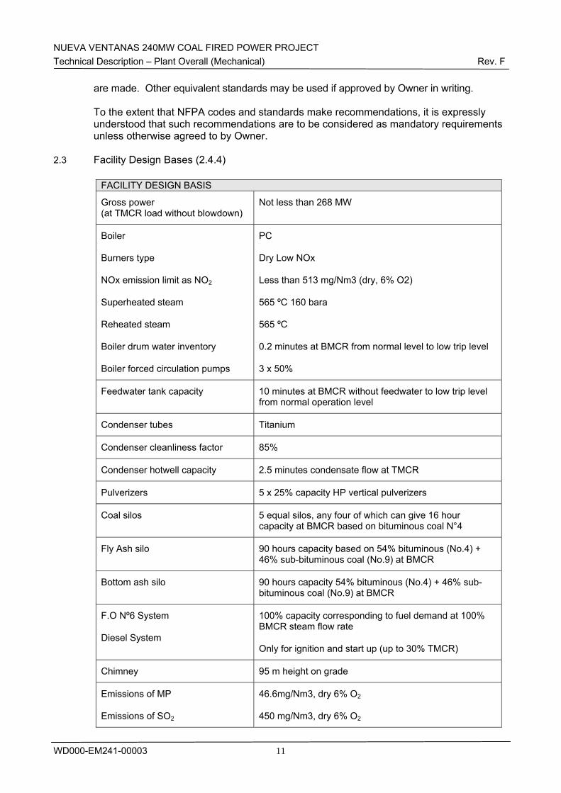
NUEVA VENTANAS 240MW COAL FIRED POWER PROJECT Technical Description – Plant Overall (Mechanical) Rev. F
WD000-EM241-00003
11
are made. Other equivalent standards may be used if approved by Owner in writing. To the extent that NFPA codes and standards make recommendations, it is expressly understood that such recommendations are to be considered as mandatory requirements unless otherwise agreed to by Owner.
2.3 Facility Design Bases (2.4.4)
FACILITY DESIGN BASIS
Gross power (at TMCR load without blowdown)
Not less than 268 MW
Boiler
Burners type
NOx emission limit as NO2
Superheated steam
Reheated steam
Boiler drum water inventory
Boiler forced circulation pumps
PC
Dry Low NOx
Less than 513 mg/Nm3 (dry, 6% O2)
565 ºC 160 bara
565 ºC
0.2 minutes at BMCR from normal level to low trip level
3 x 50%
Feedwater tank capacity 10 minutes at BMCR without feedwater to low trip level from normal operation level
Condenser tubes Titanium
Condenser cleanliness factor 85%
Condenser hotwell capacity 2.5 minutes condensate flow at TMCR
Pulverizers 5 x 25% capacity HP vertical pulverizers
Coal silos 5 equal silos, any four of which can give 16 hour capacity at BMCR based on bituminous coal N°4
Fly Ash silo 90 hours capacity based on 54% bituminous (No.4) + 46% sub-bituminous coal (No.9) at BMCR
Bottom ash silo 90 hours capacity 54% bituminous (No.4) + 46% sub-bituminous coal (No.9) at BMCR
F.O Nº6 System
Diesel System
100% capacity corresponding to fuel demand at 100% BMCR steam flow rate
Only for ignition and start up (up to 30% TMCR)
Chimney 95 m height on grade
Emissions of MP
Emissions of SO2
46.6mg/Nm3, dry 6% O2
450 mg/Nm3, dry 6% O2
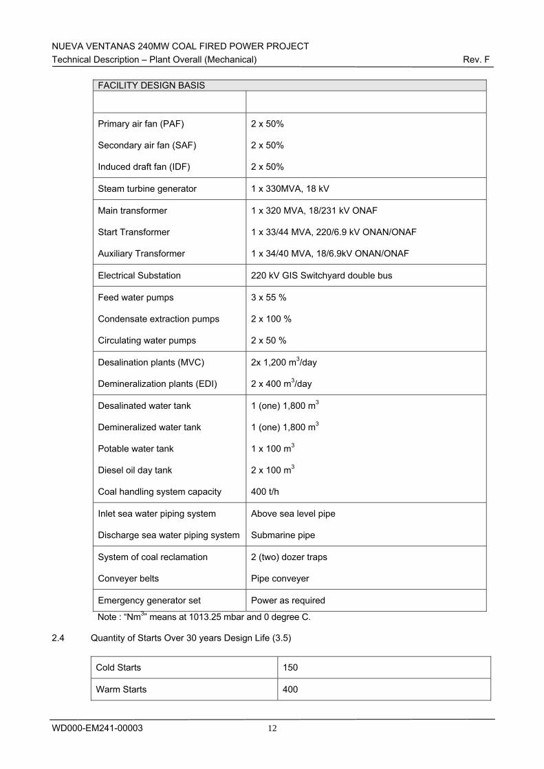
NUEVA VENTANAS 240MW COAL FIRED POWER PROJECT Technical Description – Plant Overall (Mechanical) Rev. F
WD000-EM241-00003
12
FACILITY DESIGN BASIS
Primary air fan (PAF)
Secondary air fan (SAF)
Induced draft fan (IDF)
2 x 50%
2 x 50%
2 x 50%
Steam turbine generator 1 x 330MVA, 18 kV
Main transformer
Start Transformer
Auxiliary Transformer
1 x 320 MVA, 18/231 kV ONAF
1 x 33/44 MVA, 220/6.9 kV ONAN/ONAF
1 x 34/40 MVA, 18/6.9kV ONAN/ONAF
Electrical Substation 220 kV GIS Switchyard double bus
Feed water pumps
Condensate extraction pumps
Circulating water pumps
3 x 55 %
2 x 100 %
2 x 50 %
Desalination plants (MVC)
Demineralization plants (EDI)
2x 1,200 m3/day
2 x 400 m3/day
Desalinated water tank
Demineralized water tank
Potable water tank
Diesel oil day tank
Coal handling system capacity
1 (one) 1,800 m3
1 (one) 1,800 m3
1 x 100 m3
2 x 100 m3
400 t/h
Inlet sea water piping system
Discharge sea water piping system
Above sea level pipe
Submarine pipe
System of coal reclamation
Conveyer belts
2 (two) dozer traps
Pipe conveyer
Emergency generator set Power as required
Note : “Nm3” means at 1013.25 mbar and 0 degree C.
2.4 Quantity of Starts Over 30 years Design Life (3.5)
Cold Starts 150
Warm Starts 400
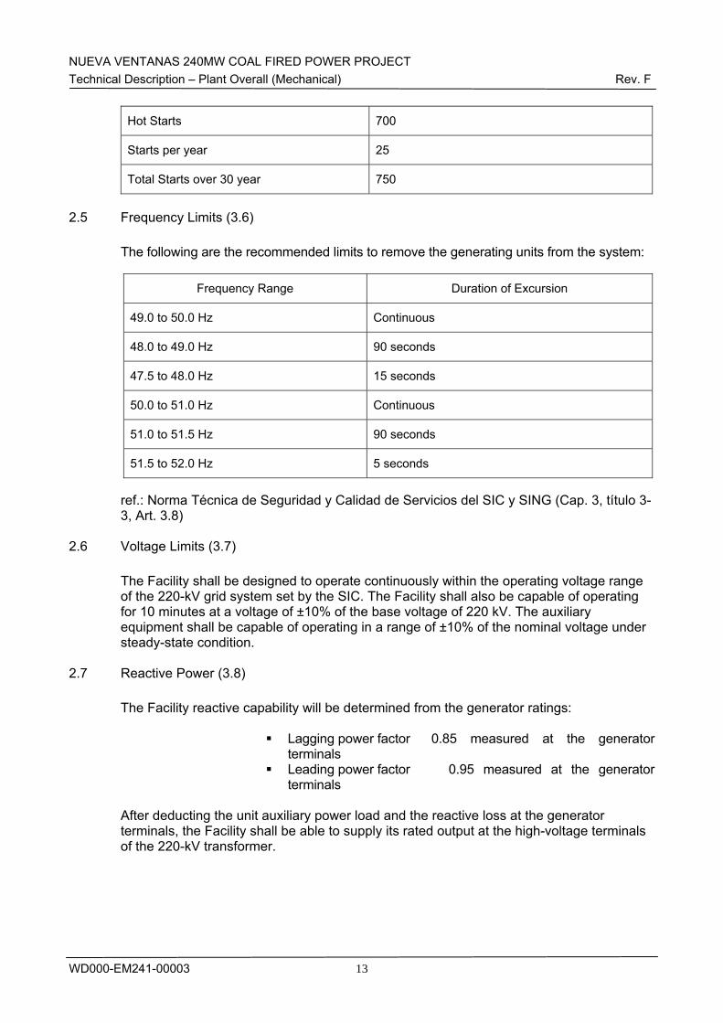
NUEVA VENTANAS 240MW COAL FIRED POWER PROJECT Technical Description – Plant Overall (Mechanical) Rev. F
WD000-EM241-00003
13
Hot Starts 700
Starts per year 25
Total Starts over 30 year 750
2.5 Frequency Limits (3.6)
The following are the recommended limits to remove the generating units from the system:
Frequency Range Duration of Excursion
49.0 to 50.0 Hz Continuous
48.0 to 49.0 Hz 90 seconds
47.5 to 48.0 Hz 15 seconds
50.0 to 51.0 Hz Continuous
51.0 to 51.5 Hz 90 seconds
51.5 to 52.0 Hz 5 seconds
ref.: Norma Técnica de Seguridad y Calidad de Servicios del SIC y SING (Cap. 3, título 3-3, Art. 3.8)
2.6 Voltage Limits (3.7)
The Facility shall be designed to operate continuously within the operating voltage range of the 220-kV grid system set by the SIC. The Facility shall also be capable of operating for 10 minutes at a voltage of ±10% of the base voltage of 220 kV. The auxiliary equipment shall be capable of operating in a range of ±10% of the nominal voltage under steady-state condition.
2.7 Reactive Power (3.8)
The Facility reactive capability will be determined from the generator ratings:
Lagging power factor 0.85 measured at the generator terminals
Leading power factor 0.95 measured at the generator terminals
After deducting the unit auxiliary power load and the reactive loss at the generator terminals, the Facility shall be able to supply its rated output at the high-voltage terminals of the 220-kV transformer.
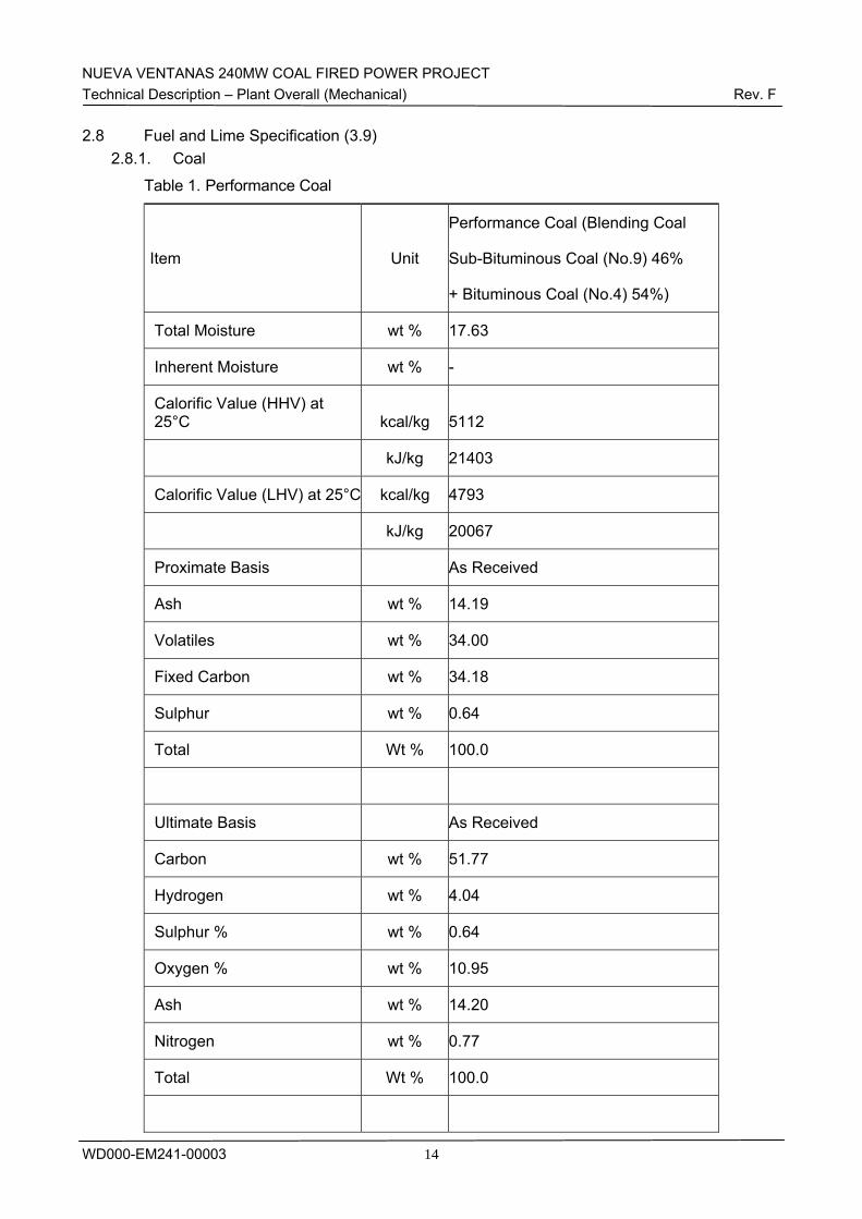
NUEVA VENTANAS 240MW COAL FIRED POWER PROJECT Technical Description – Plant Overall (Mechanical) Rev. F
WD000-EM241-00003
14
2.8 Fuel and Lime Specification (3.9) 2.8.1. Coal
Table 1. Performance Coal
Item Unit
Performance Coal (Blending Coal
Sub-Bituminous Coal (No.9) 46%
+ Bituminous Coal (No.4) 54%)
Total Moisture wt % 17.63
Inherent Moisture wt % -
Calorific Value (HHV) at 25°C kcal/kg 5112
kJ/kg 21403
Calorific Value (LHV) at 25°C kcal/kg 4793
kJ/kg 20067
Proximate Basis As Received
Ash wt % 14.19
Volatiles wt % 34.00
Fixed Carbon wt % 34.18
Sulphur wt % 0.64
Total Wt % 100.0
Ultimate Basis As Received
Carbon wt % 51.77
Hydrogen wt % 4.04
Sulphur % wt % 0.64
Oxygen % wt % 10.95
Ash wt % 14.20
Nitrogen wt % 0.77
Total Wt % 100.0
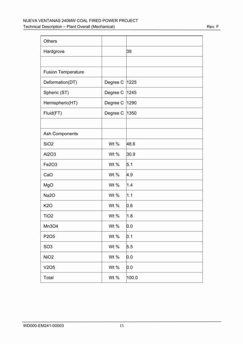
NUEVA VENTANAS 240MW COAL FIRED POWER PROJECT Technical Description – Plant Overall (Mechanical) Rev. F
WD000-EM241-00003
15
Others
Hardgrove 39
Fusion Temperature
Deformation(DT) Degree C 1225
Spheric (ST) Degree C 1245
Hemispheric(HT) Degree C 1290
Fluid(FT) Degree C 1350
Ash Components
SiO2 Wt % 48.6
Al2O3 Wt % 30.9
Fe2O3 Wt % 5.1
CaO Wt % 4.9
MgO Wt % 1.4
Na2O Wt % 1.1
K2O Wt % 0.6
TiO2 Wt % 1.8
Mn3O4 Wt % 0.0
P2O5 Wt % 0.1
SO3 Wt % 5.5
NiO2 Wt % 0.0
V2O5 Wt % 0.0
Total Wt % 100.0
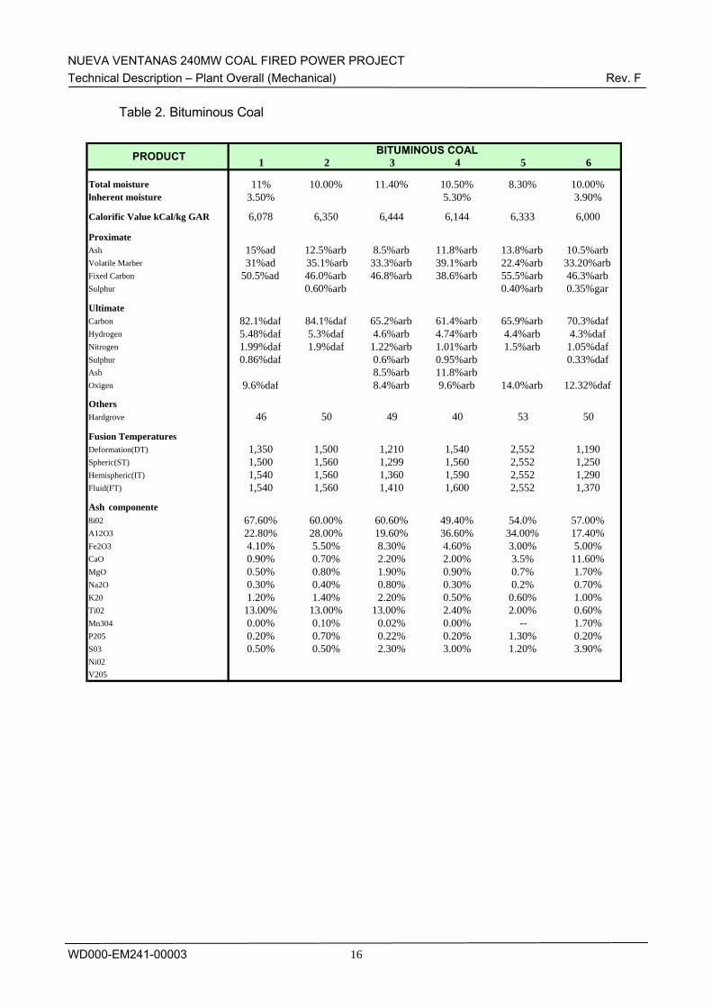
NUEVA VENTANAS 240MW COAL FIRED POWER PROJECT Technical Description – Plant Overall (Mechanical) Rev. F
WD000-EM241-00003
16
Table 2. Bituminous Coal
1 2 3 4 5 6
Total moisture 11% 10.00% 11.40% 10.50% 8.30% 10.00%lnherent moisture 3.50% 5.30% 3.90%
Calorific Value kCal/kg GAR 6,078 6,350 6,444 6,144 6,333 6,000
Proximate Ash 15%ad 12.5%arb 8.5%arb 11.8%arb 13.8%arb 10.5%arbVolatile Marber 31%ad 35.1%arb 33.3%arb 39.1%arb 22.4%arb 33.20%arbFixed Carbon 50.5%ad 46.0%arb 46.8%arb 38.6%arb 55.5%arb 46.3%arbSulphur 0.60%arb 0.40%arb 0.35%gar
Ultimate Carbon 82.1%daf 84.1%daf 65.2%arb 61.4%arb 65.9%arb 70.3%dafHydrogen 5.48%daf 5.3%daf 4.6%arb 4.74%arb 4.4%arb 4.3%dafNitrogen 1.99%daf 1.9%daf 1.22%arb 1.01%arb 1.5%arb 1.05%dafSulphur 0.86%daf 0.6%arb 0.95%arb 0.33%dafAsh 8.5%arb 11.8%arbOxigen 9.6%daf 8.4%arb 9.6%arb 14.0%arb 12.32%daf
Others Hardgrove 46 50 49 40 53 50
Fusion Temperatures Deformation(DT) 1,350 1,500 1,210 1,540 2,552 1,190Spheric(ST) 1,500 1,560 1,299 1,560 2,552 1,250Hemispheric(IT) 1,540 1,560 1,360 1,590 2,552 1,290Fluid(FT) 1,540 1,560 1,410 1,600 2,552 1,370
Ash componente 8i02 67.60% 60.00% 60.60% 49.40% 54.0% 57.00%A12O3 22.80% 28.00% 19.60% 36.60% 34.00% 17.40%Fe2O3 4.10% 5.50% 8.30% 4.60% 3.00% 5.00%CaO 0.90% 0.70% 2.20% 2.00% 3.5% 11.60%MgO 0.50% 0.80% 1.90% 0.90% 0.7% 1.70%Na2O 0.30% 0.40% 0.80% 0.30% 0.2% 0.70%K20 1.20% 1.40% 2.20% 0.50% 0.60% 1.00%Ti02 13.00% 13.00% 13.00% 2.40% 2.00% 0.60%Mn304 0.00% 0.10% 0.02% 0.00% -- 1.70%P205 0.20% 0.70% 0.22% 0.20% 1.30% 0.20%S03 0.50% 0.50% 2.30% 3.00% 1.20% 3.90%Ni02 V205
BITUMINOUS COALPRODUCT
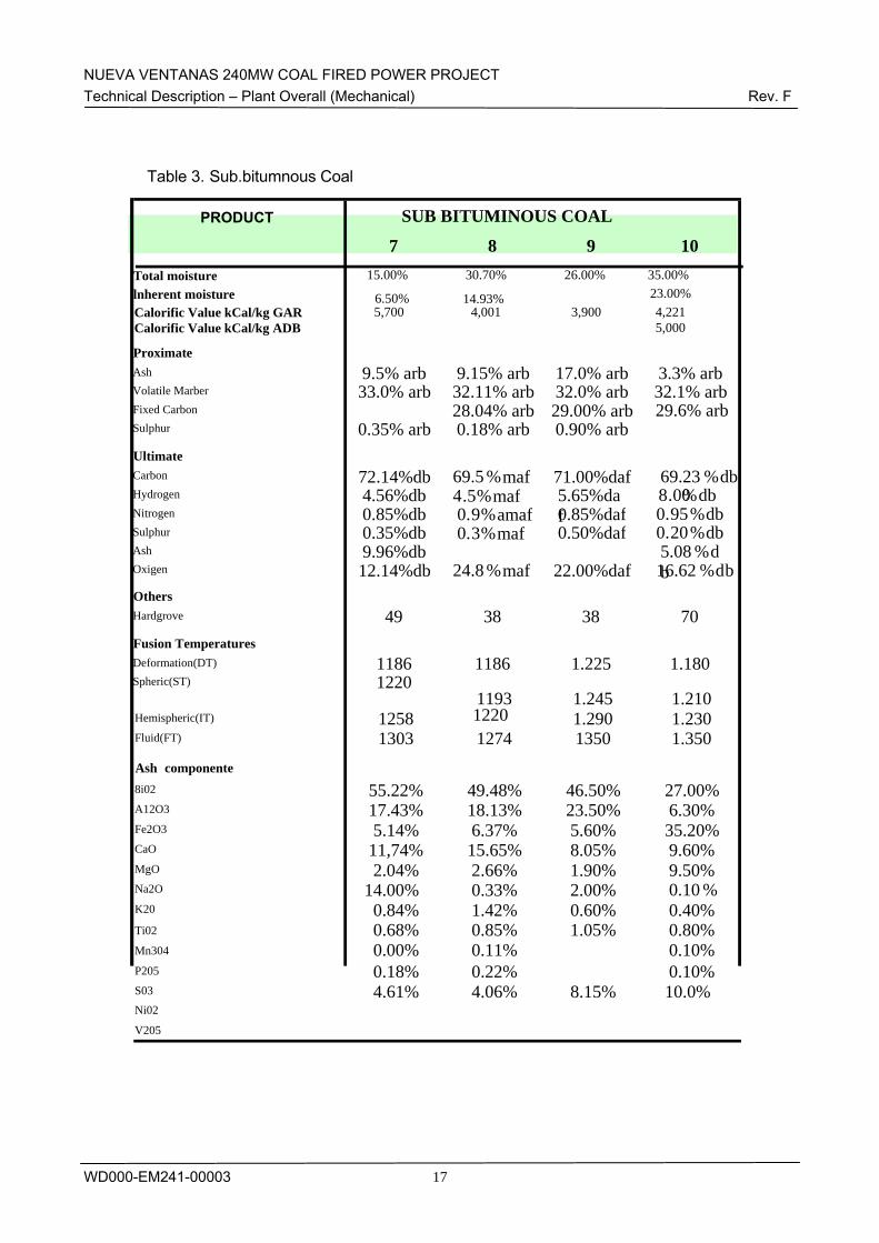
NUEVA VENTANAS 240MW COAL FIRED POWER PROJECT Technical Description – Plant Overall (Mechanical) Rev. F
WD000-EM241-00003
17
Table 3. Sub.bitumnous Coal
7 8 9 10
Total moisture 15.00% 30.70% 26.00% 35.00% lnherent moisture 6.50% 14.93% 23.00% Calorific Value kCal/kg GAR Calorific Value kCal/kg ADB
5,700 4,001 3,900 4,221 5,000
Proximate Ash 9.5% arb 9.15% arb 17.0% arb 3.3% arbVolatile Marber 33.0% arb 32.11% arb 32.0% arb 32.1% arbFixed Carbon 28.04% arb 29.00% arb 29.6% arbSulphur 0.35% arb 0.18% arb 0.90% arb Ultimate Carbon 72.14%db 69.5 %maf 71.00%daf 69.23 %dbHydrogen 4.56%db 4.5%maf 5.65%da
f8 . 00 %db
Nitrogen 0.85%db 0.9%amaf 0.85%daf 0. 95 %db Sulphur 0.35%db 0.3%maf 0.50%daf 0. 20 %db Ash 9.96%db 5.08 %d
b Oxigen 12.14%db 24.8 %maf 22.00%daf 16.62 %d bOthers Hardgrove 49 38 38 70 Fusion TemperaturesDeformation(DT) 1186 1186 1.225 1.180 Spheric(ST) 1220
1193 1.245 1.210 Hemispheric(IT) 1258 1220 1.290 1.230 Fluid(FT) 1303 1274 1350 1.350
Ash componente 8i02 55.22% 49.48% 46.50% 27.00% A12O3 17.43% 18.13% 23.50% 6.30% Fe2O3 5.14% 6.37% 5.60% 35.20% CaO 11,74% 15.65% 8.05% 9.60% MgO 2.04% 2.66% 1.90% 9.50% Na2O 14.00% 0.33% 2.00% 0.10 % K20 0.84% 1.42% 0.60% 0.40% Ti02 0.68% 0.85% 1.05% 0.80% Mn304 0.00% 0.11% 0.10% P205 0.18% 0.22% 0.10% S03 4.61% 4.06% 8.15% 10.0% Ni02 V205
SUB BITUMINOUS COALPRODUCT
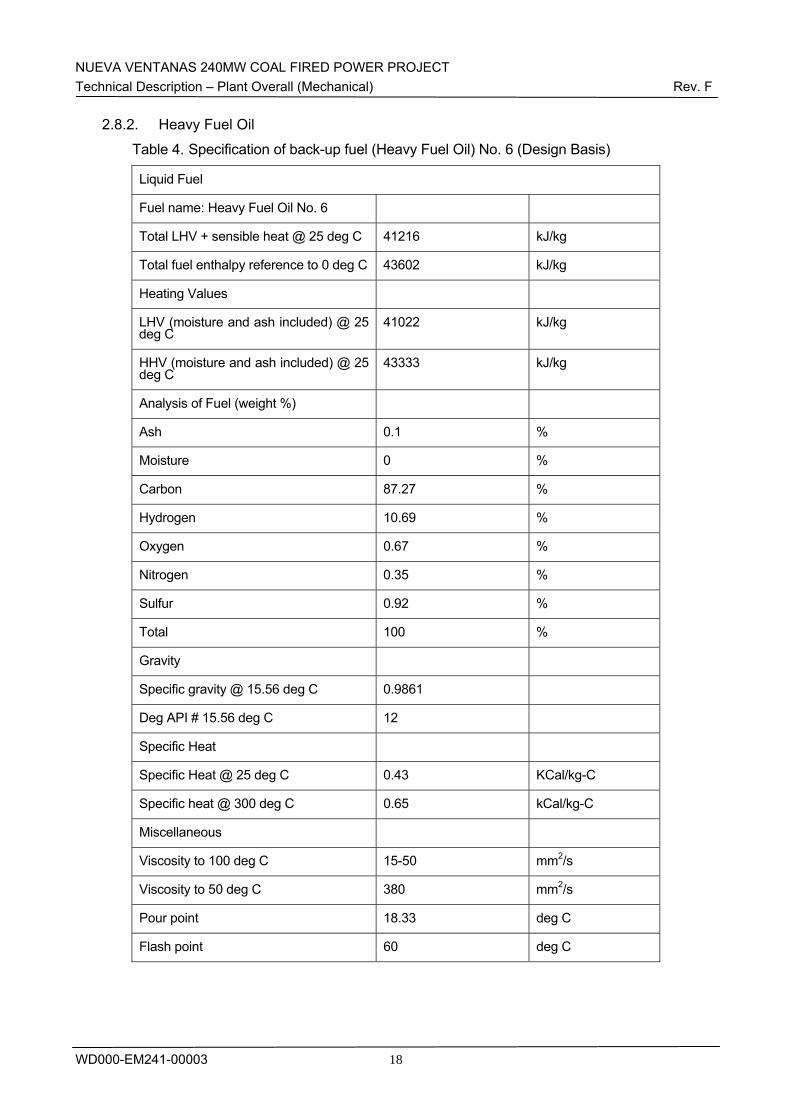
NUEVA VENTANAS 240MW COAL FIRED POWER PROJECT Technical Description – Plant Overall (Mechanical) Rev. F
WD000-EM241-00003
18
2.8.2. Heavy Fuel Oil
Table 4. Specification of back-up fuel (Heavy Fuel Oil) No. 6 (Design Basis)
Liquid Fuel
Fuel name: Heavy Fuel Oil No. 6
Total LHV + sensible heat @ 25 deg C 41216 kJ/kg
Total fuel enthalpy reference to 0 deg C 43602 kJ/kg
Heating Values
LHV (moisture and ash included) @ 25 deg C
41022 kJ/kg
HHV (moisture and ash included) @ 25 deg C
43333 kJ/kg
Analysis of Fuel (weight %)
Ash 0.1 %
Moisture 0 %
Carbon 87.27 %
Hydrogen 10.69 %
Oxygen 0.67 %
Nitrogen 0.35 %
Sulfur 0.92 %
Total 100 %
Gravity
Specific gravity @ 15.56 deg C 0.9861
Deg API # 15.56 deg C 12
Specific Heat
Specific Heat @ 25 deg C 0.43 KCal/kg-C
Specific heat @ 300 deg C 0.65 kCal/kg-C
Miscellaneous
Viscosity to 100 deg C 15-50 mm2/s
Viscosity to 50 deg C 380 mm2/s
Pour point 18.33 deg C
Flash point 60 deg C
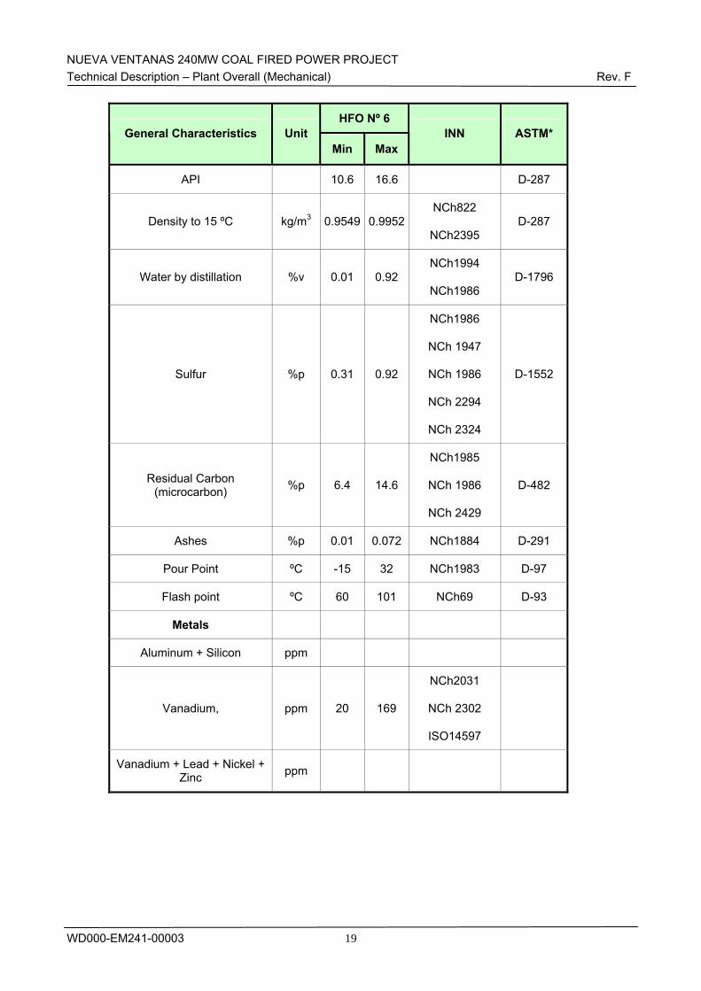
NUEVA VENTANAS 240MW COAL FIRED POWER PROJECT Technical Description – Plant Overall (Mechanical) Rev. F
WD000-EM241-00003
19
HFO Nº 6 General Characteristics Unit
Min MaxINN ASTM*
API 10.6 16.6 D-287
Density to 15 ºC kg/m3 0.9549 0.9952NCh822
NCh2395 D-287
Water by distillation %v 0.01 0.92 NCh1994
NCh1986 D-1796
Sulfur %p 0.31 0.92
NCh1986
NCh 1947
NCh 1986
NCh 2294
NCh 2324
D-1552
Residual Carbon (microcarbon) %p 6.4 14.6
NCh1985
NCh 1986
NCh 2429
D-482
Ashes %p 0.01 0.072 NCh1884 D-291
Pour Point ºC -15 32 NCh1983 D-97
Flash point ºC 60 101 NCh69 D-93
Metals
Aluminum + Silicon ppm
Vanadium, ppm 20 169
NCh2031
NCh 2302
ISO14597
Vanadium + Lead + Nickel + Zinc ppm
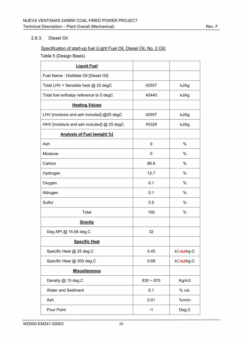
NUEVA VENTANAS 240MW COAL FIRED POWER PROJECT Technical Description – Plant Overall (Mechanical) Rev. F
WD000-EM241-00003
20
2.8.3. Diesel Oil Specification of start-up fuel (Light Fuel Oil, Diesel Oil, No. 2 Oil)
Table 5 (Design Basis)
Liquid Fuel
Fuel Name : Distillate Oil [Diesel Oil]
Total LHV + Sensible heat @ 25 degC 42557 kJ/kg
Total fuel enthalpy reference to 0 degC 45440 kJ/kg
Heating Values
LHV [moisture and ash included] @25 degC 42557 kJ/kg
HHV [moisture and ash included] @ 25 degC 45329 kJ/kg
Analysis of Fuel [weight %]
Ash 0 %
Moisture 0 %
Carbon 86.6 %
Hydrogen 12.7 %
Oxygen 0.1 %
Nitrogen 0.1 %
Sulfur 0.5 %
Total 100 %
Gravity
Deg API @ 15.56 deg.C 32
Specific Heat
Specific Heat @ 25 deg.C 0.45 kCalJ/kg-C
Specific Heat @ 300 deg.C 0.69 kCalJ/kg-C
Miscellaneous
Density @ 15 deg.C 830 ~ 870 Kg/m3
Water and Sediment 0.1 % vol.
Ash 0.01 %m/m
Pour Point -1 Deg.C
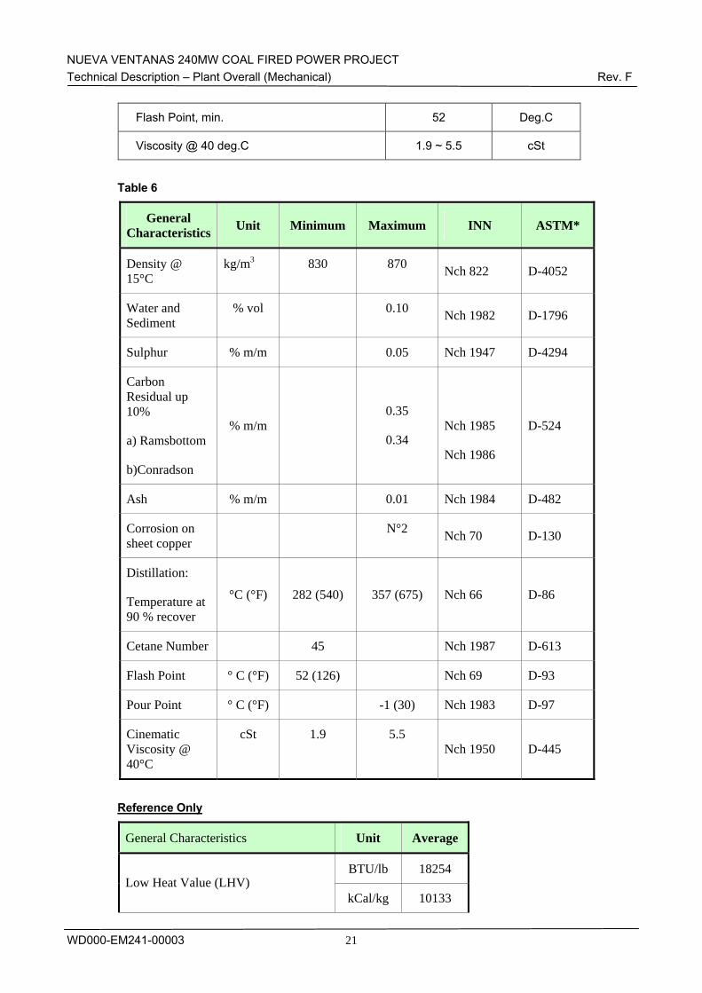
NUEVA VENTANAS 240MW COAL FIRED POWER PROJECT Technical Description – Plant Overall (Mechanical) Rev. F
WD000-EM241-00003
21
Flash Point, min. 52 Deg.C
Viscosity @ 40 deg.C 1.9 ~ 5.5 cSt
Table 6
General Characteristics Unit Minimum Maximum INN ASTM*
Density @ 15°C
kg/m3 830 870 Nch 822 D-4052
Water and Sediment
% vol 0.10 Nch 1982 D-1796
Sulphur % m/m 0.05 Nch 1947 D-4294
Carbon Residual up 10%
a) Ramsbottom
b)Conradson
% m/m
0.35
0.34
Nch 1985
Nch 1986
D-524
Ash % m/m 0.01 Nch 1984 D-482
Corrosion on sheet copper
N°2 Nch 70 D-130
Distillation:
Temperature at 90 % recover
°C (°F) 282 (540) 357 (675) Nch 66 D-86
Cetane Number 45 Nch 1987 D-613
Flash Point ° C (°F) 52 (126) Nch 69 D-93
Pour Point ° C (°F) -1 (30) Nch 1983 D-97
Cinematic Viscosity @ 40°C
cSt 1.9 5.5 Nch 1950 D-445
Reference Only
General Characteristics Unit Average
BTU/lb 18254 Low Heat Value (LHV)
kCal/kg 10133
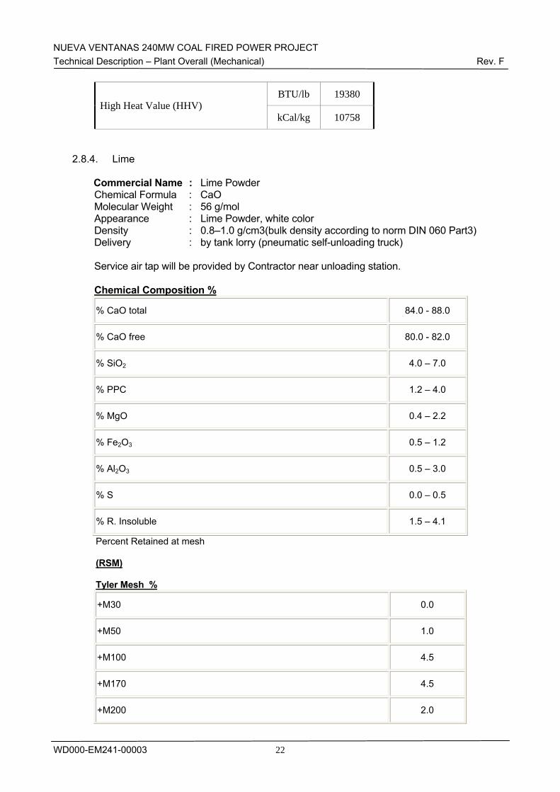
NUEVA VENTANAS 240MW COAL FIRED POWER PROJECT Technical Description – Plant Overall (Mechanical) Rev. F
WD000-EM241-00003
22
BTU/lb 19380 High Heat Value (HHV)
kCal/kg 10758
2.8.4. Lime Commercial Name : Lime Powder Chemical Formula : CaO Molecular Weight : 56 g/mol Appearance : Lime Powder, white color Density : 0.8–1.0 g/cm3(bulk density according to norm DIN 060 Part3) Delivery : by tank lorry (pneumatic self-unloading truck)
Service air tap will be provided by Contractor near unloading station.
Chemical Composition %
% CaO total 84.0 - 88.0
% CaO free 80.0 - 82.0
% SiO2 4.0 – 7.0
% PPC 1.2 – 4.0
% MgO 0.4 – 2.2
% Fe2O3 0.5 – 1.2
% Al2O3 0.5 – 3.0
% S 0.0 – 0.5
% R. Insoluble 1.5 – 4.1
Percent Retained at mesh
(RSM)
Tyler Mesh %
+M30 0.0
+M50 1.0
+M100 4.5
+M170 4.5
+M200 2.0
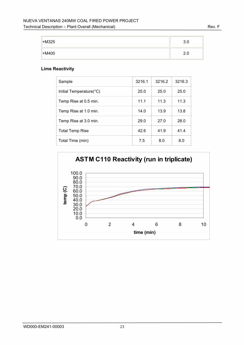
NUEVA VENTANAS 240MW COAL FIRED POWER PROJECT Technical Description – Plant Overall (Mechanical) Rev. F
WD000-EM241-00003
23
+M325 3.0
+M400 2.0
Lime Reactivity
Sample 3216.1 3216.2 3216.3
Initial Temperature(°C) 25.0 25.0 25.0
Temp Rise at 0.5 min. 11.1 11.3 11.3
Temp Rise at 1.0 min. 14.0 13.9 13.8
Temp Rise at 3.0 min. 29.0 27.0 28.0
Total Temp Rise 42.6 41.9 41.4
Total Time (min) 7.5 8.0 8.0
ASTM C110 Reactivity (run in triplicate)
0.010.020.030.040.050.060.070.080.090.0
100.0
0 2 4 6 8 10
time (min)
tem
p (C
)
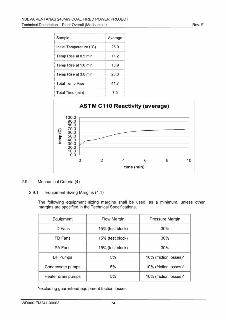
NUEVA VENTANAS 240MW COAL FIRED POWER PROJECT Technical Description – Plant Overall (Mechanical) Rev. F
WD000-EM241-00003
24
Sample Average
Initial Temperature (°C) 25.0
Temp Rise at 0.5 min. 11.2
Temp Rise at 1.0 min. 13.9
Temp Rise at 3.0 min. 28.0
Total Temp Rise 41.7
Total Time (min) 7.5
ASTM C110 Reactivity (average)
0.010.020.030.040.050.060.070.080.090.0
100.0
0 2 4 6 8 10
time (min)
tem
p (C
)
2.9 Mechanical Criteria (4)
2.9.1. Equipment Sizing Margins (4.1)
The following equipment sizing margins shall be used, as a minimum, unless other margins are specified in the Technical Specifications.
Equipment Flow Margin Pressure Margin
ID Fans 15% (test block) 30%
FD Fans 15% (test block) 30%
PA Fans 15% (test block) 30%
BF Pumps 5% 10% (friction losses)*
Condensate pumps 5% 10% (friction losses)*
Heater drain pumps 5% 10% (friction losses)*
*excluding guaranteed equipment friction losses.
NUEVA VENTANAS 240MW COAL FIRED POWER PROJECT Technical Description – Plant Overall (Mechanical) Rev. F
WD000-EM241-00003
25
2.9.2. General Mechanical Requirements (4.2) This section covers the general mechanical requirements for the Facility. All equipment shall be suitably designed and constructed for safe, proper and continuous unattended operation under all operating conditions without strain, vibration, corrosion or other operating difficulties. The equipment should conform to high standards of engineering design, workmanship and construction and should be capable of operating efficiently and without excessive wear or maintenance.
1) Castings and Forging The quality requirements DIN 1681, DIN 17245, DIN 17445 or equivalent other industry standards should be taken as the minimum requirements and tolerances for castings and forgings. Depending on the differing requirements in respect of freedom of defects, cast steel according to DIN 17245 (Table 3) is to be supplied preferentially in the quality grades 1 (less 32 bar, 400°C) and III (above 80 bar, 480°C). The technical requirements of castings, forgings and wrought products for STG and its auxiliary equipment shall be in accordance with the Subcontractor’s standard practices. 2) Iron Castings Cast iron is not to be used for any part of equipment, which is in tension or which is subjected to impact, or to a working temperature exceeding 100°C. Materials for iron castings should comply with the following specifications according to the standards DIN 1691, DIN 1692, DIN 1693, DIN 1694 and DIN 17006 or equivalent other international standards. 3) Steel Forging The quality requirements of DIN 2821, DIN 7522 or other equivalent international standards, together with the other provisions of this specification should be taken as the minimum requirements for steel forging. All forging are to be manufactured from basic electric steel or fully killed acid open-hearth steel. Consideration shall be given to the use of vacuum-degassed steels in appropriate cases. Forging shall be free of cracks externally or internally, extensive non-metallic inclusions and surface defects which cannot be removed by subsequent machining. Each forging shall be suitably marked with an identification number, which shall be transferred throughout all final machining stages. The identification number shall be marked on all documents and test certificates relative to the forging. 4) Welding All welding shall comply with the requirements of AWS and ASME as applicable. All quality control and inspection of welding (both during fabrication and construction) shall be in accordance with the QA/QC Manual. UNI EN can be applied with Owner’s approval.
NUEVA VENTANAS 240MW COAL FIRED POWER PROJECT Technical Description – Plant Overall (Mechanical) Rev. F
WD000-EM241-00003
26
5) Lubrication Lubrication of equipment shall be done with the same lubricant under all climatic conditions. The Contractor shall submit a comprehensive list of lubricants including among other information, the characteristics of the lubricants, name, service and estimated consumption rate for equipment. 6) Miscellaneous Pumps The following represents general requirements for pumps. The special requirements for important pumps (e.g. feedwater pumps, main condensate pumps, and main cooling water pumps) are stated in the respective chapter. All pumps shall be so designed that they are suitable for continuous operation unless otherwise specified. Pumps installed for parallel operation or as standby sets are to be of the same design, i.e. interchangeable. Lifting lugs and eyes and other special tackle shall be provided as necessary to permit easy handling of the pump and its components. Standard-type pumps with suitable characteristics shall be considered. All accessories and the overall design of pump sets are to be such that they are suitable for automatic operation as planned for the relevant systems.
7) Pump Design All pumps shall be designed to withstand a test pressure of 1.5 times the maximum possible shut-off pressure and following the Subcontractor’s standards. All pump parts and accessories in contact with the pumped fluid shall be constructed of materials specifically designed for the conditions and nature of the pumped fluid, and be resistant to erosion and corrosion. Preferably, pumps shall be provided with mechanical shaft seals of the highest quality and reliability. In all cases where pumps are fitted with stuffing boxes, the shafts shall be provided with protective sleeves in a suitable material. In accordance with the individual requirements, devices for cooling, heating, flushing or locking the shaft seals shall be provided. The pump glands or mechanical seals shall be so arranged that packing or fitting of replacement seals can be carried out with the minimum of disruption to plant operation. Liquid sealing shall be provided for operating under vacuum conditions. The pump casing shall be design to allow the withdrawal of the impeller and shaft from the casing without disturbing any of the main pipework and valves carrying the pumped fluid. In general, all horizontal pumps with draw-out rotors shall be fitted with a coupling to facilitate disassembly without removing the motor. Pullout design shall be applied to the circulating water pumps. For other vertical pumps, Subcontractor’s standard design shall be applied.
NUEVA VENTANAS 240MW COAL FIRED POWER PROJECT Technical Description – Plant Overall (Mechanical) Rev. F
WD000-EM241-00003
27
Each horizontal pump shall be mounted with its drive on a common base plate of rigid construction. Vertical pumps shall be provided with foundation frames. For submersible pumps suitable frames shall be provided in the pump sump. It shall however be possible to remove these pumps without entering the sump. Pumps must be carefully set to ensure that the net positive suction head available under all operating conditions will be adequate for the type of pump employed. The NPSH values shall be referred to the least favorable operating conditions - lowest atmospheric pressure, lowest level of water on the suction side of the pump, and highest temperature of the pumped fluid. A safety margin over the maximum required NPSH shall be provided according to the Subcontractor’s recommendations and corresponding standards. Static balancing and, as far as applicable dynamic balancing of individual parts and of the assembled pump shall be carried out on the rotating parts of centrifugal pumps if required according to the Subcontractor’s standard practices. Where necessary the pumps shall be fitted with devices to ensure a minimum flow.
8) Bearings All bearings shall be designed according to specifications provided by the Subcontractor.
9) Pump Characteristics When multiple pumps are installed for the same service, they shall be suitable for unrestricted parallel operation. The pump flow and head characteristics should be such that the head will continuously increase with decreasing flow, with maximum head being reached at zero flow.
10) Pump Fittings All pumps shall be installed with isolating valves, a non-return valve and suction and discharge pressure gauges unless otherwise stated in accordance with Subcontractor’s standard. All couplings shall be supplied with removable type guards. Couplings and gears must have a rated capacity of the greatest of (1) 110% of the maximum potential power transmission requirement or (2) the Subcontractor’s standard recommendation. All pumps other than submersible pumps shall have temporary strainers fitted in the suction pipework during all initial running and commissioning. Permanent strainers shall be provided as recommended by Subcontractor’s standard specification or as may be prudent and in accordance with Good Industry Practices. Vent valves shall be provided for all pumps at suitable locations on the pump casing unless the pump is self-venting. Drainage facilities shall be provided on all pump casings or adjacent pipework to facilitate the pump maintenance. All positive displacement pumps shall be fitted with appropriate discharge relief valves capable of venting the maximum pump flow either to the suction side of the pump or to the supply tank.
NUEVA VENTANAS 240MW COAL FIRED POWER PROJECT Technical Description – Plant Overall (Mechanical) Rev. F
WD000-EM241-00003
28
11) Piping
Refer to Design Criteria for Piping. 12) Valves Refer to Design Criteria for Piping. 13) Materials Requirements for Piping Components and Valves Refer to Design Criteria for Piping.
14) Guidelines for the Design and Construction of Pressure Vessels
Pressure vessels shall be designed, manufactured and tested in accordance with the requirements of the ASME Boiler and Pressure Vessel Code, section VIII "Pressure Vessels" or equivalent recognized standard. All flanged connections to pressure vessels shall conform to at least pressure class 150 according to ASME B16.5.
Threaded connections shall conform to pressure class 3000 according to ASME B16.11.
The pressure vessels shall be provided with connections for all pipework, together with connection and tapping points for instrumentation. Drains, relief valves, and any access stairways and handrails necessary for safe operation and easy maintenance shall be provided.
If any degree of vacuum can occur the pressure vessel shall be designed for full vacuum even if vacuum breakers are installed on the vessel.
Cold condensate tank shall be designed in accordance with the API Standard 650. Corrosion allowance shall be considered. In addition to the nozzles necessary for the process technology, the items listed below shall be provided as a minimum.
• 1(one) manhole (minimum nominal bore 500 mm) for vessels of 1.0 m diameter and above
• 2 (two) handholds (minimum size 200 mm) for vessels below 1.0 m diameter
• 2 (two) spare nozzles
• 1 (one) drain nozzle
All nozzles shall be provided with flanges and must allow an elastic pipe arrangement is possible.
Manhole covers of nominal diameter 500 mm and larger shall be provided with swinging arms.
Vessels standing vertically shall have legs made of steel tubing. Welded-on supporting feet shall support vertical vessels suspended from steel structures or ceilings.
NUEVA VENTANAS 240MW COAL FIRED POWER PROJECT Technical Description – Plant Overall (Mechanical) Rev. F
WD000-EM241-00003
29
The saddle plates welded to the vessel shall be of the same material as the vessel. All vessels are to be provided with a Subcontractor's nameplate at an easily visible spot and shall be provided with the following information:
• Subcontractor's name or Subcontractor's symbol
• Serial number
• Year of construction
• Capacity in cubic meters
• Test pressure
• Identification number in accordance with the plant classification system
• Description of the vessel itself
15) Insulation
All insulation shall comply with ASTM standards for thermal insulation material. Insulation and cladding for piping, valves, specialties, gas ducts, and equipment shall be provided to:
• Reduce noise if required to meet the environmental noise criteria
• Provide personnel protection
• Minimize thermal losses
The following or approved equal materials shall be used for hot equipment and piping for temperatures up to:
• 590°C - calcium silicate, rock or mineral wool
• 370°C - calcium silicate, cellular glass, rock or mineral wool
When there are several layers of insulation, it must be ensured that there is sufficient overlapping of the insulation at the joints. The overlapping in the lagging should ensure that no rain water can enter and soak the insulation. The drum metal temperature probes shall be properly guarded against false reading by rain water contacting the probes.
The insulation and lagging shall be arranged with expansion joints, if required, so that all surfaces shall be effectively insulated whether in the hot or cold position and to prevent cracking or distortion of the insulation due to thermal expansion of the equipment. Corner flashing shall be fastened to provide a tight fit and accommodate the thermal expansion.
Special attention shall be paid to the ease of maintenance of each part of the Facility and straightforward access to insulated components requiring maintenance shall be possible.
The basis for calculation of thermal insulation thickness shall be a surface temperature of 60°C at an ambient temperature of 15° C and at a wind velocity of 1 m/s.
NUEVA VENTANAS 240MW COAL FIRED POWER PROJECT Technical Description – Plant Overall (Mechanical) Rev. F
WD000-EM241-00003
30
Insulation for personnel protection shall be such that surface temperatures do not exceed 60°C.
Insulation for condensation prevention shall be applied to equipment operating at temperatures below the maximum dew point, where condensation could form to the detriment of Facility structures or equipment or cause discomfort to operating personnel.
Asbestos is not allowed to be used for insulation or any other purposes in the Facility. Mineral wool mats must be stable, in shape, chemically inert, free of sulphur and alkali, resistant to water and steam, non-flammable and capable of withstanding continuous exposure to the pipe or equipment design temperature. The insulating mats used for insulation of stainless steel equipment shall have a chloride content of less than 0.15%.
The density of mineral wool mats shall be not less than 100 kg/m3 under a loading of 100 kg/m2.
The Subcontractor must state the nominal thickness of the mats on the mats. The thermal conductivity of the material at 100° C shall not exceed 0.055 W/m2. All insulated equipment shall be provided with a jacket of aluminium sheeting or galvanized sheeting, which must have the following minimum thickness:
Outer insulation diameter
up to 350 mm
Sheet thickness
0.8 mm
Outer insulation diameter
Above 350 mm
Sheet thickness
1.0 mm
Tanks and other large
Equipment
Sheet thickness
1.2 mm
Tank tops to be accessible for opening of manhole or inspection of instruments shall be provided with insulation strong enough to support a person’s weight. The sheets shall be secured and connected at the longitudinal seams with stainless self-tapping screws (five screws per meter).
At the longitudinal and circumferential joints the sheets shall overlap by at least 50 mm so as to drain off spilled liquid and not to trap the liquid in the insulation.
The seams and penetrations of any sheet metal insulating jacket installed outdoors shall be sealed against penetration of water by means of a suitable insulating tape.
The inside of the aluminium jacket shall be protected against contact corrosion from the wire mesh of the insulating mats by suitable means (e.g. Kraft paper).
In the case of the greater insulation thickness (60 mm upwards) spacers shall be provided to ensure a uniform insulating thickness on all sides and a perfectly circular shape of the sheet metal jacket.
NUEVA VENTANAS 240MW COAL FIRED POWER PROJECT Technical Description – Plant Overall (Mechanical) Rev. F
WD000-EM241-00003
31
All flanges and fittings shall be provided with two-piece or multi-part caps made of aluminium sheet of the specified thickness.
The shaped caps of the welded-in fittings shall be made longer by approximately twice the insulation thickness so that the welding seams will be exposed after removal of the cap. Where possible, the caps should be fitted with a clamping strip or lever hook to facilitate assembly.
All manholes when possible shall be provided with removable insulated covers secured with easily accessible clamps or screws.
Tanks and other devices shall be insulated in the same way as pipes, except that the insulating material must not be attached by wire but by using strong galvanized steel bands.
Spacers shall be welded to devices only if essential for satisfactory retention of insulation and provided it is approved in writing by the device Subcontractor.
Compensators are to be insulated with detachable, two-piece or multiparty caps. The sheet metal jacket shall be formed of aluminium sheets. The insulation mats are to be secured in the sheet metal caps by means of hooks and clips.
In the case of trace-heated pipelines, the heating pipes shall be provided with an aluminium radiation plate. The radiation plate shall be attached eccentrically to the pipe axis in the area of the tracing only.
Whenever insulation is necessary only for the protection of personnel, it shall be applied around that portion of the pipeline length or to that surface of the equipment that is located within 2.50 m above the tread surface of, or within 1.20 m horizontally beyond the side or end of any floor, platform, walkway, stair or ladder.
Where necessary, drain lines and valves shall be provided with a contact guard of min. 30-mm thickness against accidental contact, and this shall be installed in the same way as the other insulation. In the case of insulating against condensation, the outer protection of the insulation must not only provide a mechanical barrier but also it must be installed so as to be vapor-tight, to avoid the entry of moisture through water vapor diffusion into the insulating layer.
For this purpose bitumen sealers, bitumen binders or special paint finishes shall be used.
16) Test and Inspection Test and inspection of all equipment shall be in accordance with the Test and Inspection Plan contained in the QA/QC Program and Plan.
2.10 Noise Criteria Sound levels measured in accordance with Applicable Laws at any section of the property on the Site will be no more than the dB(A) level required by Applicable Laws and/or Applicable Permits when the Facility is operating at any and all loads which shall be demonstrated by Contractor in a Completed Performance Test, taking into account the operation of Owner’s existing adjacent facilities.
NUEVA VENTANAS 240MW COAL FIRED POWER PROJECT Technical Description – Plant Overall (Mechanical) Rev. F
WD000-EM241-00003
32
NUEVA VENTANAS 240MW COAL FIRED POWER PROJECT Technical Description – Plant Overall (Mechanical) Rev. F
WD000-EM241-00003
33
3. PULVERIZED COAL FIRED BOILER (4.3)
3.1 Function
The functions of the Pulverized Coal Fired Boiler are: to generate the steam using the coals such as bituminous coals, blending of bituminous and
sub.bituminous coals as main fuel and heavy fuel oil as support and emergency fuel. to feed the steam to the Steam Turbine. to feed the steam to the sootblowers. to feed the steam to the auxiliary steam system during start-up and low load operation.
3.2 Design Bases The boiler and its auxiliaries are designed with the following design bases:
3.2.1. Codes and Standards The boiler and its auxiliaries are designed and manufactured in accordance with the following codes and standards, including manufacturer’s design criteria and practices :
ANSI American National Standards Institute ASME American Society of Mechanical Engineers ASTM American Society for Testing and Materials NFPA National Fire Protection Association AISC American Institute of Steel Construction UBC Uniform Building Codes Manufacturer’s design criteria and practices
and other applicable international codes and standards 3.2.2. Capacity Criteria of Boiler and its Associated Equipment
1) Boiler Maximum Continuous Rating Boiler Maximum Continuous Rating (BMCR) is 103% of TMCR (steam turbine maximum continuous steam flow rate) at the rated conditions required for plant output guarantee (measured at the economizer inlet). This steam flow rate at BMCR is calculated as 103 % of the feedwater flow rate at the inlet of economizer as referred to the heat balance diagram for TMCR, after deducted the sampling flowrate (assumed as 500kg/h) from boiler, that is, Main steam flow rate at BMCR load = 103% x (FW flowrate at economiser inlet for TMCR load minus sampling flowrate) = 103% x (741,941kg/h – 500kg/h) = 103% x (741,441kg/h) = 763,684 kg/h
2) Fuels and boiler design criteria The boiler shall be capable of generating the steam flow required at BMCR load when firing any of the bituminous coals (No.1 to No.6), or any of the blended coals made by mixing the specified subbituminous coals No. 9 (max 46% coal in blending ratio) with any of the bituminous coals (No.1 to No.6). The maximum % of each subbituminous coal in blending ratio shall be as follows:
− Subbituminous coal No. 7 : 100% − Subbituminous coal No. 8 : 31% − Subbituminous coal No. 9 : 46%
NUEVA VENTANAS 240MW COAL FIRED POWER PROJECT Technical Description – Plant Overall (Mechanical) Rev. F
WD000-EM241-00003
34
− Subbituminous coal No. 10 : 26% The guaranteed plant performance shall be based on the Performance Coal (blend of 46% subbituminous coal (No.9) and 54% bituminous coal (No.4)). The boiler shall be designed such that the steam temperatures at the outlet header of reheater can be maintained within 568ºC±5ºC between 65%TMCR and 100%BMCR at steady state and constant pressure without gas recirculation fans when firing any of the bituminous coals (100% of No.1 to No.6), and the blending of subbituminous coal and bituminous coal (54%(min.)). The minimum stable load of the boiler shall be 40% of TMCR with any uniformly blended coal during normal operation and without any supplementary fuel. Heavy fuel oil shall be used for operation of the power plant between 10% and 40% TMCR load during start-up operation, and for emergencies, expected to be one week every five years of plant operation at 100% BMCR steam flow rate with lower superheated and reheated steam temperatures than those at BMCR when firing coal. The expected range of sulfur percentage of heavy fuel oil shall be within 0.92%wt (max.), 0.68%wt (average) and 0.31%wt (min.). The temperatures of main steam and reheat steam will be varied according to the load levels. Diesel oil will be used for ignition and start up operation up to 30% TMCR.
3) Capacity criteria of pulverizers Expected performance curves shall be prepared based on the characteristics of bituminous coals (No.1 to No.6) and blending coals of any specified subbituminous coal and any specified bituminous coal (54 %( min.)). The expected performance curves shall have the capacity terms in the vertical line (y - axis) and the terms of kinds of coals of bituminous coals (No.1 to 6), and blending coals of subbituminous coal and bituminous coal (54%(min.)) in the horizontal line (x - axis).
4) Capacity criteria for coal silo and ash silo
− Coal silo : According to the coal consumption at BMCR when firing bituminous coal No.4.
− Ash silo : According to the ash generation at BMCR when firing blending coal of 54% bituminous coal No. 4 and 46% subbituminous coal N°9.
3.2.3. The boiler will be designed:
1) for outdoor installation without roof
2) for balanced draft type
3) for constant pressure and based load operation
4) for controlled (assisted) circulation type
5) to use the diesel oil for ignition and initial start-up upto 30% TMCR
6) to use the heavy fuel oil for start-up operation between 10% TMCR and 40%TMCR load
7) to use the bituminous coal for normal operation
8) to use the blending coal of bituminous coal and subbituminous coal according to the
NUEVA VENTANAS 240MW COAL FIRED POWER PROJECT Technical Description – Plant Overall (Mechanical) Rev. F
WD000-EM241-00003
35
capacity criteria of the boiler for normal operation
9) to use the heavy fuel oil in case of interruption of coal supply system for an intermediate time at 100% BMCR steam flow rate operation
10) 5 (five) x 25% pulverizers to be sized to reach BMCR with 4 operating pulverizers in the degraded condition immediately before overhaul
11) to be possible for change from coal or coal blends mixture to oil or only coal and vice versa must be possible without load reduction
12) to be suitable for raising pressure on diesel oil alone
13) to be supplied the steam for sootblowers from intermediate superheater stage
14) to be built with ASME stamps
3.2.4. The boiler will be provided with:
1) centrifugal fan design with backward curved airfoil blades. The control of the fans shall be done by variable inlet vanes.
2) steam heated air heaters designed so that the boiler exit gas temperature does not drop below the acid dew point
3) regenerative air preheaters with two types of drives (one is normal main, the other one is standby)
4) chimney of a height of 95 m above grade (+5.1m above mean sea level), including an elevator which allows to raise at least two persons and the weight of equipment for the maintenance of the CEMS probes system
5) drain and blowdown system (one continuous blowdown flash tank and one intermittent blowdown tank)
6) complete structural steelwork for boiler, coal silos, elevator shaft, pipe bridge and belt conveyor bridges and for auxiliary equipment
7) roof and dust proof cladding for tripper conveyor gallery
8) dust proof enclosure of all conveyor bridges (except pipe conveyor)
9) all necessary lagging, metallic cladding and insulation for all the equipment covered by this specification
10) complete enclosure for steam drum and partial enclosure for burner operating floors.
11) weather hoods, etc.
12) sootblowers for boiler furnace walls, economizer, superheaters and reheater, airheaters
13) coal mixture and handling system (five equal silos, any four of which can give 16 hour capacity at BMCR based on bituminous coal No. 4)
14) coal preparation and firing equipment, including coal pulverizers, coal feeders, sealing air supply system and associated auxiliaries
NUEVA VENTANAS 240MW COAL FIRED POWER PROJECT Technical Description – Plant Overall (Mechanical) Rev. F
WD000-EM241-00003
36
15) primary air system, including hot and cold air ducts and dampers
16) inerting system for pulverizers with steam, complete with all relevant equipment
17) sealing air supply system, complete with ducts and filters
18) diesel oil ignition and firing system
19) heavy oil firing system
20) combustion air system, including air ductworks, forced draft fan (2X50%), regenerative type air heaters, steam heated air preheaters and condensate return system
21) flue gas system, including flue gas duct works, induced draft fan (2X50%) with inlet vane controllers
22) utility stations for air, steam and water from connection branch of main distribution supply up to the consumer
23) provisions for stand-still conservation (nitrogen storage) of the steam generator
24) coal feeders of gravimetric type
25) Low NOx type coal burner in order not to exceed the emission limits
26) 2 (two) access stairs
27) 1 (one) elevator
3.2.5. Boiler operating conditions
3.2.5.1 At TMCR
1) Fuel fired Performance Coal HFO
2) HP steam at SH outlet - steam pressure : 165.0 bara 164.1 bara - steam temperature : 568.0 °C 517.0 °C - steam flow : 741,941 kg/h 741,941 kg/h
3) IP steam at HRH outlet - steam pressure : 42.31 bara 38.93 bara - steam temperature : 568.0 °C 486.0 °C - steam flow : 669,889 kg/h 650,822 kg/h
4) Feedwater at eco. inlet - FW pressure : 180.1 bara 179.2 bara - FW temperature : 255.2 °C 250.1 °C - FW flow : 741,941 kg/h 741,941 kg/h
5) Cold reheat steam at terminal point - Steam pressure : 44.75 bara 41.14 bara - Steam temperature : 372.4 °C 322.9 °C - Steam flow : 669,889 kg/h 650,822 kg/h
6) Exhaust gas temperature
at air preheater outlet : 131 °C 138 °C
NUEVA VENTANAS 240MW COAL FIRED POWER PROJECT Technical Description – Plant Overall (Mechanical) Rev. F
WD000-EM241-00003
37
7) Higher heating value (at 15°C) : 21,403 kJ/kg 43,333 kJ/kg
8) Boiler efficiency : 86.35 % 77.10 % (Based on energy balance method in the ASME PTC 4)
9) Fuel consumption : 112,128 kg/h 57,840 kg/h
3.3 Description
3.3.1. General Description Pulverised coal fired boiler with drum balanced draft controlled circulation will be supplier by Doosan heavy industries. 1) Steam generator description
a) Unit description The unit is a Controlled Circulation Radiant Reheat (CC+RR) steam generator. Major auxiliary equipment provided by or through DHI (Doosan Heavy Industries) consists of air preheaters and gravimetric coal feeders, air and gas duct control & shutoff dampers and slide gates,a soot blowing system and gas temperature probe, cranes(hoists),water gauges and water level indicators,scanner and pulverizer seal air booster fans,forced draft (FD) and primary air (PA), induced draft ID) fans,pulverizer,boiler circulating pump &,safety and SH power relief valves,and miscellaneous valves and instrumentation used in the system. The boiler is designed to generate steam in the most efficient manner,while minimizing the amount of heat lost during steam generation. Incorporated in the boiler design and controls are a number of safety features to ensure optimum safety during normal and emergency operating conditions. The steam generator consists of the furnace area (front),and back pass area (rear) through which the flue gases pass before entering the air heaters. After leaving the air heaters the flue gases continue through the flue gas cleaning equipment,ID fans and then to the stack. Located around the steam generator are the various auxiliary systems which are necessary to meet the specific air,fuel and water requirements for steam generation.
b) Component description
The steam generator is of the open bottom,top supported design. The steam generator consists of drums, headers and tube assemblies located throughout the steam generator structure to provide for the flow of water and the processing of steam. The components are part of the pressure part structure and are designed to meet specific flow requirements. The furnace is the area where combustion of the fuel takes place and is formed by four waterwalls of welded tube panels. The furnace wall tubes are supplied from the lower furnace waterwall drums. Water and saturated steam generated in the furnace wall tubes collects in the upper waterwall headers and is discharged into the steam drum.
NUEVA VENTANAS 240MW COAL FIRED POWER PROJECT Technical Description – Plant Overall (Mechanical) Rev. F
WD000-EM241-00003
38
Superheater and reheater assemblies located in the upper region of the furnace and backpass use the heat from the flue gases to increase the temperature of the steam to the design values. The flue gas passing across the economizer banks in the backpass heats the incoming feedwater that flows through the economizer tubes. The furnace has been designed for oil and pulverized coal firing. Fuel firing is directed through the corner furnace windboxes which house the oil and coal firing equipment. Five individual pulverizers supply the pulverized coal to the furnace. Bottom ash produced in the combustion process is removed by the furnace bottom ash system. Most of the fly ash remaining in the flue gas is removed by the flue gas cleaning equipment. Combustion air for fuel firing is supplied by the FD fans through associated ductwork and air heating equipment. Flue gases carrying the products of combustion are removed and delivered to the stack by the ID fans.
2) Water and steam circuits
a) Description
In a Controlled Circulation steam generator,boiler circulating pumps placed in the downcomer circuits ensure proper circulation of water through the waterwalls. Orifices installed in the inlet of each water circuit maintain an apportionate flow of water through the circuit. Feedwater enters the unit through the economizer and is mixed with boiler water in the steam drum. Water flows from the steam drum through the downcomers to the pump suction manifold. The boiler circulating pumps take water from the suction manifold and discharge it,via the pump discharge lines,into the furnace front drum. Furnace lower right and left side drums assure proper distribution of the water to the furnace lower rear drum. In the furnace lower front,side and rear drums,the boiler water passes through orifices that feed the furnace wall tubes and the economizer recirculating line. From the furnace lower front,rear and side drums,the water rises through furnace waterwall tubes where it absorbs heat. The front wall tubes,rear wall tubes,rear wall hanger tubes,rear arch tubes,furnace screen tubes, furnace extended side wall tubes,and furnace side wall tubes form parallel flow paths. The resulting mixture of water and steam collects in the waterwall outlet headers and is discharged into the steam drum through the riser tubes. In the steam drum,the steam and water are separated. The steam then goes to the superheater and water is returned to the water side of the steam drum to be recirculated.
b) Steam drum internals The function of the steam drum internals is to separate the water from the steam generated in the furnace walls and to reduce the dissolved solids content of the steam to below the prescribed limit. Separation is generally performed in three stages,with the first two stages occurring in the turbo-separators and the final stage taking place at the top of the drum just before the steam enters the connecting tubes.
NUEVA VENTANAS 240MW COAL FIRED POWER PROJECT Technical Description – Plant Overall (Mechanical) Rev. F
WD000-EM241-00003
39
The steam/water mixture entering the top of the steam drum from the furnace risertubes sweeps down along both sides of the drum through the narrow annulus formed by a baffle extending over the length of the drum. The baffle is eccentric with the drum shell and effects adequate velocity and uniform heat transfer, thereby maintaining the entire drum surface at a uniform temperature. At the lower end of the baffle the steam/water mixture is forced upward through two rows of turboseparators. The primary stage of the turbo-separator is formed by two concentric cans. Spinner blades impart a centrifugal motion to the mixture of steam and water flowing upward through the inner can,thereby throwing the water to the outside and forcing the steam to the inside. The water is collected by a skim-off lip above the spinner blades and is returned to the lower part of the drum through the annulus between the two cans. The steam proceeds up to the secondary separator stage. The secondary stage consists of two opposed banks of closely spaced,thin, corrugated metal plates which direct the steam through a tortuous path,forcing entrained water against the corrugated plates. Since the velocity is relatively low,this water does not get picked up again,but runs down the plates and off the second stage lips at the two steam outlets. From the secondary separators the steam flows upward to the third and final stage of separators. This stage consists of four rows of corrugated plate dryers extending the length of the drum. The steam flows with relatively low velocity through the path formed by the closely spaced layers of corrugated plates. Water runs down the plates into the drain trough located between the rows of plate dryers. Drain pipes return this water to the water side of the steam drum.
c) Economizer The function of the economizer is to preheat the boiler feedwater before it is introduced into the steam drum by recovering some of the heat of the flue gases leaving the boiler. The economizer is located below the rear horizontal superheater assemblies in the lower section of the boiler back pass. It is arranged in horizontal rows in such a manner that each row is in line in relation to the row above and below. All tube circuits originate from the economizer inlet header,and discharge into two economizer junction headers that are connected with the economizer outlet header by two rows of economizer hanger tubes. Feedwater is supplied to the economizer inlet header via feed stop and check valves. The feedwater flow is upward through the economizer,that is,in counterflow to the hot flue gases. Most efficient heat transfer is thereby accomplished,while the possibility of steam generation within the economizer is minimized by the upward water flow. From the outlet header,the feedwater is led to the steam drum through economizer links. The economizer,recirculating line,which connects the economizer inlet header with the furnace lower rear drum, provides a means of ensuring water flow through the economizer during start-ups. This helps prevent steaming. The valve in this line must be open during unit start-up until continuous feedwater flow is established.
NUEVA VENTANAS 240MW COAL FIRED POWER PROJECT Technical Description – Plant Overall (Mechanical) Rev. F
WD000-EM241-00003
40
The frequency with which soot blowers are used depends entirely on local conditions. When the economizer is first placed in operation,the economizer soot blowers should be blown about once every shift. Observation of the increase in draft loss between blowings will determine how long an interval may be set as a standard. In many cases,it has been found that blowing the economizer soot blowers once a day or less is sufficient.
d) Boiler circulating pumps The unit is equipped with three boiler circulating pumps to provide controlled circulation of the boiler water through the waterwall system. The pumps are suspended from a common suction manifold,from which they take their suction, and discharge into the lower front waterwall drum. Each pump has two discharge lines,each equipped with a stop/check valve. The boiler circulating pumps,each consist of a single stage centrifugal pump and a submerged,or wet,stator induction motor mounted in a common pressure vessel. The vessel is made up of three main parts: the pump casing,the motor housing and the motor cover. To protect pump during start-up, following items shall be checked ; 1. Suction vessel water level normal Low water level in suction vessel may cause pump troubles such as cavitation, pump dry operation and so on. 2. Suction valve open Pump must be started up and operated with suction valve opened. 3. Motor cooler cooling water flow low It is very important to maintain necessary cooling water flow to motor cooler to keep motor from overheating and fatal damage to motor. Even though alarm criteria is 70% of normal flow, cooling water system should be designed to facilitate the supply of rated cooling water. 4. Heat barrier cooling water flow low It is very important to maintain necessary cooling water flow to heat barrier to keep motor from being damaged by heat from pump side especially during stand-by condition. Even though alarm criteria is 70% of normal flow, cooling water system should be designed to facilitate the supply of rated cooling water. 5. Motor cavity temperature high high Pump must be started up with motor cavity temperature below 65℃ to avoid damage to motor during start-up.
e) Superheater (a) Steam flow
The superheater is composed of five basic stages or sections; namely the superheater (SH) vertical platen,or finishing,section,the SH division panel section,the low temperature superheater (LTSH) pendant section,the LTSH
NUEVA VENTANAS 240MW COAL FIRED POWER PROJECT Technical Description – Plant Overall (Mechanical) Rev. F
WD000-EM241-00003
41
horizontal section,and the back pass wall and roof section. The SH vertical platen section is located directly above the furnace in front of the furnace arch. And it is located directly above the furnace between the front wall and the SH vertical platen section. The LTSH pendant section is located in the furnace rear back pass directly behind the pack pass front wall screen tubes and above the LTSH horizontal section. The LTSH horizontal section is located above the economizer in the furnace back pass. The back pass wall and roof section forms the back pass side wall tubes,back pass front wall tubes,back pass front wall screen tubes,back pass roof tubes, back pass rear wall tubes. From the steam drum,the main steam flow is through the connecting pipes to the roof inlet header located furnace front upper part. From the roof inlet header, the steam flows through the furnace roof tubes to the roof outlet header and the back pass upper side inlet headers. From the back pass upper side inlet headers,the steam flow is through the backpass side wall tubes to the back pass lower side outlet headers and the back pass front wall inlet headers. From the back pass front wall inlet headers,the steam flow is through the back pass front wall tubes and back pass front wall screen tubes,the back pass roof tubes,and the back pass rear wall tubes to the LTSH horizontal inlet header. From the LTSH horizontal inlet header,the steam flows through the LTSH horizontal lower and upper assemblies and the LTSH pendant assemblies to the LTSH outlet header. From here,the steam is carried to the SH desuperheaters by the SH links. The SH links from the SH desuperheaters carry steam to the SH division inlet headers. These headers supply steam through the SH division panels to the SH division outlet headers. From the SH division outlet headers, the steam is carried to the SH vertical platen inlet header. This header supplies steam through the SH vertical platen assemblies to the SH vertical platen outlet headers and the SH outlet leads. NOTE: Fluid (steam) cooled spacer tubes originating at the SH division inlet headers, and discharging through the fluid cooled spacer riser tubes into the SH platen inlet headers,maintain the alignment of the division panels and SH vertical platen assemblies and prevent them from swaying excessively. Additional fluid (steam) cooled spacer tubes,originating from the back pass lower front header, maintain alignment of the SH vertical platen assemblies and the reheater vertical spaced platen front assemblies and discharge through the associated fluid cooled spacer riser tubes into the SH division outlet headers. Superheated steam from the SH vertical platen outlet header goes to the high pressure stages of the turbine via the main steam lines. After passing through the high pressure stages of the turbine,steam is returned
NUEVA VENTANAS 240MW COAL FIRED POWER PROJECT Technical Description – Plant Overall (Mechanical) Rev. F
WD000-EM241-00003
42
to the reheater via the cold reheat lines.
(b) Protection and control
As long as there is a fire in the furnace,adequate protection must be provided for the superheater elements. This is especially important during periods when there is no demand for steam,such as when starting up or shutting down the unit. During these periods of no steam flow through the turbine,adequate flow through the superheater is assured by means of drains and vents in the superheater headers and links and the main steam piping. Safety valves on the main steam lines,set below the lowest set steam drum safety valve,provide another means of protection by assuring adequate flow through the superheater should steam demand suddenly and unexpectedly drop. A power control valve on each of the superheater outlet leads,set below the lowest set superheater safety valve,is provided as a working valve to give an initial indication of excessive steam pressure. The valves are each equipped with a shutoff valve to permit isolation for maintenance. The relieving capacity of the power control valves is not included in the total relieving capacity of the safety valves required by the Boiler Code. During all start-ups,care must be taken not to overheat the superheater elements. The firing rate must be controlled to prevent the furnace exit gas temperature from exceeding 537℃. The temperature probe located in the upper furnace side wall should be used to measure the furnace exit gas temperatures. Thermocouples installed on various superheater terminal tubes above the furnace roof serve to provide a continuous indication of element metal temperatures during start-up and when the unit is carrying load. In addition to the permanent thermocouples,temporary thermocouples provide supplementary means of establishing temperature characteristics during initial operation.
(c) General
It is essential that suitable arrangements are made to assure cleanliness of the external and internal surfaces of the superheater at all times. Fly ash and/or slag accumulations result in unequal gas distribution,inefficient heat transfer,and possible localized overheating. Suitably located soot blowers,operated in the proper cycle,normally provide adequate means of keeping surfaces clean. The external surfaces of the superheater should be inspected regularly for cleanliness. Slagging must be kept to a minimum by proper use of soot blowers. Extreme buildups must be removed immediately. Local slagging may become a cause of overheating of element tubes,possibly resulting in tube failures. Furthermore,it may restrict the gas flow causing uneven heat transfer and creating further operating difficulties. Proper feedwater treatment,and control of steam quality and carry-over are essential to assure cleanliness of interior surfaces of superheaters.
NUEVA VENTANAS 240MW COAL FIRED POWER PROJECT Technical Description – Plant Overall (Mechanical) Rev. F
WD000-EM241-00003
43
Overloads,fluctuating load,high water level,foaming,high concentrations, etc.,all contribute to deposits on interior surfaces. Accumulation of these deposits inside the tubes will lead to unit failure. Care must be taken to assure that condensate quality spray water is used for the desuperheaters to avoid carryover of solids into the superheater and the turbine blades. Periodic checks of steam pressure drops across the superheater under identical load conditions usually indicate whether or not solid deposits are present within the elements.
f) Superheater desuperheater
Spray-type superheater (SH) desuperheaters is installed in the connecting links between the low temperature superheater (LTSH) outlet header and the SH division inlet headers. Temperature reduction is accomplished by spraying water into the path of the steam through a nozzle at the inlet end of the desuperheater. It is essential that the spray water be chemically pure and free of suspended and dissolved solids, containing only approved volatile organic treatment material,in order to prevent chemical deposition in the superheater and carry-over of solids to the turbine. During start-up of the unit,if desuperheating is used to match the outlet steam temperature to the turbine metal temperatures,care must be exercised so as not to spray down below a minimum of 11°C above the saturation temperature at the existing operating pressure. Desuperheating spray is not particularly effective at the low steam flows of start-up. Spray water may not be completely evaporated but be carried through the heat absorbing sections to the turbine where it can be the source of considerable damage. During start-up,alternate methods of steam temperature control should be considered.
g) Reheater (a) Steam flow
The reheater is composed of four stages,or sections; namely,the reheater (RH) vertical platen (finishing) front section,the RH vertical rear section,the RH radiant wall front section and the RH radiant wall side section. The RH vertical platen front (finishing) assemblies are located above the furnace arch between the furnace rear hanger tubes and the SH vertical platen section. The RH vertical rear assemblies are located above the furnace arch between the furnace screen tubes and the furnace rear hanger tubes. The RH radiant wall sections cover approximately the upper third of the furnace front and side waterwalls. The reheat steam flow is as follows: After passing through the high pressure stages of the turbine,steam is returned to the reheater via the cold reheat lines. The reheater desuperheaters are located in the cold reheat lines. Steam enters the reheater through the RH radiant wall front inlet headers and
NUEVA VENTANAS 240MW COAL FIRED POWER PROJECT Technical Description – Plant Overall (Mechanical) Rev. F
WD000-EM241-00003
44
the RH radiant wall side inlet headers. From the RH radiant wall front inlet headers, the steam flows through the RH radiant wall front tubes to the RH radiant wall front outlet headers. Steam from the RH radiant wall side inlet headers flows through the RH radiant wall side tubes to the RH radiant wall side outlet headers. From the RH radiant wall front and side outlet headers,the steam is carried by the RH vertical rear inlet links to the RH vertical rear inlet header. Steam from this header flows through the RH vertical rear assemblies,the RH vertical platen front assemblies to the RH vertical platen front outlet headers and RH outlet leads.
(b) Protection and control
As long as there is a fire in the furnace,adequate protection must be provided for the reheater elements. This is especially important during periods when there is no demand for steam,such as when starting up or shutting down the unit. Reheater drains and vents provide the means to boil off residual water in the reheater elements during initial firing of the boiler. Reheater safety valves,located on the hot and cold reheat piping,serve to protect the reheater should steam flow through the reheater be suddenly interrupted. During all start-ups,care must be taken not to overheat the reheater elements. The firing rate must be controlled to keep the furnace exit gas temperature from exceeding 537℃. The temperature probe,located in the upper furnace side wall,should be used to measure the furnace exit gas temperatures. Thermocouples installed on various reheater terminal tubes above the furnace roof serve to provide a continuous indication of element metal temperatures during start-up,and when the unit is carrying load. In addition to the permanent thermocouples,temporary thermocouples provide supplementary means of establishing temperature characteristics during initial operation. Steam temperature control is provided by means of windbox nozzle tilts and desuperheaters.
(c) General
It is essential that suitable arrangements are made to assure cleanliness of the external and internal surfaces of the reheater at all times. Fly ash and/or slag accumulations result in unequal gas distribution,inefficient heat transfer,and possible localized overheating. Suitably located soot blowers,operated in the proper cycle,normally provide adequate means of keeping surfaces clean. The external surfaces of the reheater should be inspected regularly for cleanliness. Slagging must be kept to a minimum by proper use of soot blowers. Extreme buildups must be removed immediately. Local slagging may become a cause of overheating of element tubes possibly resulting in tube failures. Furthermore,it may restrict the gas flow causing uneven heat transfer and creating further operating difficulties.
NUEVA VENTANAS 240MW COAL FIRED POWER PROJECT Technical Description – Plant Overall (Mechanical) Rev. F
WD000-EM241-00003
45
Proper feedwater treatment,and control of steam quality and carry-over are essential to assure cleanliness of interior surfaces of reheaters. Overloads,fluctuating load,high water level,foaming,high concentrations,etc.,all contribute to deposits on interior surfaces. Accumulation of these deposits inside the tubes will lead to unit failure. Care must be taken to assure that condensate quality spray water is used for the desuperheaters to avoid carryover of solids into the reheater and the turbine blades. Periodic checks of steam pressure drops across the reheater under identical load conditions usually indicate whether or not solid deposits are present within the elements.
h) Reheater desuperheater Spray-type reheater desuperheaters is installed in the cold reheat lines leading to the RH radiant wall front inlet headers to permit reduction of steam temperature when necessary,and to maintain the temperatures at design values,within the limits of the nozzle capacity. Temperature reduction is accomplished by spraying water into the path of the steam through a nozzle at the inlet end of the desuperheater. It is essential that the spray water be chemically pure and free of suspended and dissolved solids, containing only approved volatile organic treatment material,in order to prevent chemical deposition in the reheater and carry-over of solids to the turbine. During start-up of the unit,if desuperheating is used to match the outlet steam temperature to the turbine metal temperatures,care must be exercised so as not to spray down below a minimum of 11°C above the saturation temperature at the existing operating pressure. Desuperheating spray is not particularly effective at the low steam flows of start-up. Spray water may not be completely evaporated but be carried through the heat absorbing sections to the turbine where it can be the source of considerable damage. During start-up,alternate methods of steam temperature control should be considered.
3) Air and gas system
a) Air and flue gas system (a) Air/gas flow
Air and gas flow through the unit is handled by the forced draft (FD) fans, induced draft (ID) fans, and primary air (PA) fans. Scanner cooling air booster fans and pulverizer seal air booster fans assure that air pressures are adequate to overcome resistance in their respective systems. The air is utilized for: (1) Combustion - Secondary Air and Overfire Air. (2) Cooling - Flame Scanners. (3) Conveying and Drying of Pulverized Coal - Primary Air. (4) Sealing - Pulverizers and Coal Pipes.
NUEVA VENTANAS 240MW COAL FIRED POWER PROJECT Technical Description – Plant Overall (Mechanical) Rev. F
WD000-EM241-00003
46
(5) Sealing - Feeders. Secondary Air and Overfire Air – Combustion The secondary air for combustion is preheated by means of Ljungstrom tri-sector air heaters, one for each set of FD and ID fans. The air heater air inlet and outlet ducts are interconnected to provide a balanced airflow to the furnace and to make it possible to operate the unit at reduced rating with only one set of fans and one air heater in service. To assist in reducing the amount of NOx formed in the furnace, overfire air can be admitted to the furnace through the two upper levels of furnace main windbox Close Coupled Overfire Air (CCOFA) nozzles and through each three levels of Separated Overfire Air (SOFA) register nozzles, located above the main windboxes. Control of unit air flow is obtained by positioning the FD fan inlet vane and the ID fan inlet vane, while the distribution of secondary air to the windbox compartments is controlled by secondary air dampers. The steam heater coils at the Air Preheater air inlets are used to control the air preheater cold end temperature for corrosion control. Flame Scanner Cooling Air Flame scanner cooling air is supplied from atmosphere. Either of two 100% fans serving the flame scanner air manifold can be used to supply the cooling air pressure required. A filter upstream of each of the fans helps to assure clean air for cooling. An alarm system should indicate when a filter requires service. A scanner fan should be in service whenever a fire is in the furnace and should be kept in service until the unit is shut down and the flame scanners are cooled to their acceptable high temperature limit. Primary Air - Conveying and Drying of Pulverized Coal The air used to convey and dry the pulverized coal is referred to as primary air. Two primary air (PA) fans supply the air to the pulverizer primary air system. To assure proper drying in the pulverizers, both hot and cold air must be available; therefore, a portion of the air from the primary air fans passes through the tri-sector air preheaters. The PA fan inlet vanes are controlled to maintain a predetermined pressure in the pulverizer primary air ducts. The flow of air from the hot and cold air ducts is controlled by the hot and cold air control dampers at each pulverizer to deliver the necessary total primary air flow requirement for the pulverizer and also to maintain a predetermined outlet temperature. If a PA fan is not available for service and the other fan is operating, it must be isolated from the system by closing its outlet shutoff dampers. The number of pulverizers in service is then limited. Seal Air - Pulverizers and Coal Pipes Seal air for the pulverizer bowl hub, journal assemblies, journal springs, and
NUEVA VENTANAS 240MW COAL FIRED POWER PROJECT Technical Description – Plant Overall (Mechanical) Rev. F
WD000-EM241-00003
47
pulverizer discharge dampers is taken from the cold primary air duct to the pulverizers. Either of two booster fans in the supply duct can be used to ensure a flow of air into the pulverizer openings under all normal operating conditions. A shutoff valve in the seal air duct at each pulverizer inlet can be closed when the pulverizer is out of service for maintenance. A mechanical filter upstream of the booster fans is used to remove dust, etc. from the air supply, thus assuring a clean air supply for the pulverizer bowl hub and journals. A power operated valve in each purge air duct to the coal pipes operates in conjunction with the pulverizer discharge valves to provide a positive seal air pressure in the coal pipes when the discharge valves are closed. Seal Air – Feeders Seal air for the feeders is taken direct from the cold air duct to the pulverizers. Feeder seal air prevents hot gases from the pulverizer from entering the feeder. A shutoff valve in each feeder seal air duct makes it possible to isolate the feeders for maintenance.
(b) Flue gas flow
Flue gases travel upward in the furnace and downward through the rear gas pass and SCR system to the tri-sector air heaters. In the air preheaters, the residual heat of the flue gases is utilized to preheat the combustion and pulverizer primary air. From the tri-sector air preheaters, the gases pass through the precipitators, the ID fans, and to the stack.
(c) Operational procedures
Shutoff dampers at each FD, ID, and PA fan inlet or outlet may be used to isolate the fans for maintenance. An air preheater may be isolated by closing the associated duct dampers.
b) Scanner air system (a) Description
The scanner air system is designed to provide adequate cooling air to the flame scanners under all normal operating conditions and to initiate corrective action or alarms under adverse operating conditions. The scanner air system consists of a series of ducts which supply air taken from atmosphere air, boosted to the required pressure by either of two 100% scanner air fans, to the scanner cooling air manifolds at the tangential windboxes.
(b) Scanner air
Either of the two booster fans in the scanner cooling air system ensures an adequate supply of cooling air to the scanners during normal unit operating conditions. A supply of clean, cool air must be available to the flame scanners whenever the
NUEVA VENTANAS 240MW COAL FIRED POWER PROJECT Technical Description – Plant Overall (Mechanical) Rev. F
WD000-EM241-00003
48
furnace temperature is above 212°F (100°C). CAUTION : With the furnace hot, all flame scanners must be removed from the furnace with loss of the scanner cooling air fans. An example could be a plant electrical power failure, with the boiler on line. A filter located immediately upstream of each of the scanner booster fans removes dust and dirt which may be introduced into the system from the atmosphere. Differential pressure switches across the filters may be used to initiate "plugged" or "no filter" alarms. A differential pressure gauge may provide the operator with a local indication of the filter condition. It is recommended that pressure readings be taken and recorded immediately after a new filter is installed, and that periodic readings (at least once per shift) be taken thereafter to assist in establishing a filter cleaning schedule. The scanner fans must be powered from a reliable power source. As soon as the BMS is engaged, an alarm will appear and the primary scanner air fan will automatically receive a start command. This start command is initiated whenever the scanner air duct-to-furnace differential pressure is below the setting of the scanner fan control pressure switch [approximately 6 in. w.g. (152 mm H2O) pressure drop across the most remote scanners]. Once the minimum pressure is satisfied, the alarm will automatically reset and not activate unless the differential pressure drops below the set point. The initial low differential pressure will activate an additional alarm after a time delay of approximately 10 seconds, if the minimum differential pressure is not reached. After a start command, the primary fan must satisfy the minimum differential pressure within five seconds or the secondary fan is given a start command. If the secondary scanner fan satisfies the pressure requirement before the 10 seconds expires, the delayed alarm will not be activated. CAUTION : Scanner cooling air is very important. Should the secondary scanner air fan automatically start, it is important to quickly find the reason and resolve the problem.
c) Pulverizer seal air system Seal air for the pulverizer bowl hub, journal assemblies, journal springs and pulverizer discharge dampers is taken from the cold primary air duct to the pulverizers. Either of 2 two booster fans in the supply duct can ensure a flow of air into the pulverizer openings under all normal operating conditions. A power operated shutoff valve in the seal air duct at each pulverizer can be closed when the pulverizer is out of service for maintenance. A power operated shutoff damper in the seal air line to the coal pipes is utilized to admit seal air to the coal pipes for cooling when the pulverizer is isolated. The seal air damper is open whenever the pulverizer discharge valves are closed and is closed whenever the pulverizer discharge valves are open. A mechanical filter upstream of the booster fans removes dirt and dust from the air, ensuring a clean air supply for the pulverizer. The pulverizer seal air shutoff valves are always kept wide open. They are closed only when a pulverizer is isolated for maintenance. (a) Seal air to pulverizers
NUEVA VENTANAS 240MW COAL FIRED POWER PROJECT Technical Description – Plant Overall (Mechanical) Rev. F
WD000-EM241-00003
49
An adequate supply of clean seal air for the pulverizer is provided by the two booster fans and the filter in the seal air system. One fan normally runs continuously, with the self-positioning, transfer damper directing flow from the operating fan. The non-operating fan may be isolated for maintenance by closing the associated manual inlet shutoff damper.
(b) Seal air for feeders
Seal air for the feeders is also taken from the cold primary air duct to the pulverizers. A shutoff damper in each feeder purge air duct makes it possible to isolate a feeder for maintenance.
4) Fuel firing system
a) Pulverized coal system (a) Introduction
The system for direct firing of pulverized coal utilizes ALSTOM (ABB CE) pulverizers to pulverize the coal and a tangential firing system to admit the pulverized coal, together with the air required for combustion (secondary air), to the furnace. Crushed coal is fed to each pulverizer by its feeder (at a rate to suit the load demand). Primary air is supplied from the primary air fans to dry the coal as it is being pulverized. A portion of the primary air is pre-heated in the Ljungstrom Tri-sector air preheater. The hot and cold primary air are proportionally mixed prior to admission to the pulverizer to provide the required drying, indicated by the pulverizer outlet temperature. The primary air transports the pulverized coal through the coal piping system to the coal nozzles in the windbox assemblies. The primary air flow is measured in the air inlet duct to each pulverizer and controlled to maintain the velocities required to transport the coal through the pulverizer and coal piping. As the pulverized coal and air mixture is discharged from the coal nozzles, it is directed toward the center of the furnace to form a firing circle. Fully preheated secondary air for combustion enters the furnace around the pulverized coal nozzles and through the auxiliary air compartments directly adjacent to the coal nozzle compartments. The pulverized coal and air streams entering the furnace are initially ignited by a suitable ignition source at the nozzle exit. Above a predictable minimum loading condition the ignition becomes self-sustaining. Combustion is completed as the gases spiral up in the furnace.
(b) Combustion of pulverized coal in tangentially fired furnaces The velocity of the primary air and coal mixture inside the fuel nozzle tip is greater than the speed of flame propagation. Upon leaving the nozzle tip, the stream of coal and air rapidly spreads out and decreases in ve-locity, especially at the outer fringes where eddies form as the stream mixes with secondary air. Here flame propagation and fuel speeds equalize, resulting in ignition. As the stream advances into the furnace, ignition spreads until the entire mass is burning completely.
NUEVA VENTANAS 240MW COAL FIRED POWER PROJECT Technical Description – Plant Overall (Mechanical) Rev. F
WD000-EM241-00003
50
A large portion of the products of combustion is carried out of the furnace with the flue gas; the remainder is discharged through the furnace bottom into the ash hopper. The cyclonic mixing action provided by tangential firing turbulently mixes the burning coal particles in a constantly changing air and gas atmosphere. As the main part of the gases spiral upward in the furnace, the relatively dense solid particles are subjected to sustained turbulence, which removes the products of combustion from the particles and as-sists in the natural diffusion of oxygen through the gas film that surrounds the particles.
(c) Pulverizers The pulverizer basically is a grinding chamber with a classifier mounted above it. The pulverizing takes place in a rotating bowl in which cen-trifugal force moves the coal, delivered by the feeder, outward across the grinding ring (bull ring). Rolls revolve on journals that are attached to the separator body. They pulverize the coal sufficiently to enable the air stream through the pulverizer to pick up the coal. Springs, acting through the journal heads, provide the necessary pressure between the grinding surfaces and the coal. The rolls do not touch the grinding ring, even when the pulverizer is empty. Tram iron and other foreign material are discharged through the tramp iron spout into the pyrites hopper. The air and pulverized coal mixture passes upward into the classifier where deflector blades change the direction of the flow abruptly, causing coarse particles to be returned to the bowl for further grinding. Fine particles remaining in suspension pass through the classifier, through the pulverizer discharge valves and the coal piping to the windbox nozzles. The raw, crushed coal is delivered from the bunkers to the individual feeders, which in turn feed the coal at a controlled rate to the pulverizers. In order to avoid overloading the pulverizer motor due to overfeeding, an interrupting circuit should be used to reduce the coal feed if the motor should become overloaded and to start the coal feed again when the motor load becomes normal.
(d) Coal pipe slide gate valves
Coal pipe slide gate valves are provided in the coal pipes to the windbox coal nozzles to prevent furnace gases from traveling back into the pulverizer when it is opened for inspection or maintenance with the boiler in operation. The slide gates are usually located near the windboxes, between the inlet elbows and the coal nozzles. However, if this is not possible, they should be located as close to the windboxes as possible. NOTE : If the coal pipe slide gate valves are closed for an extended period of time (no air flow through the pulverizer and coal piping), slag bridging may occur on the coal nozzle tips. After opening the slide gate valves, and before placing the pulverizer in operation, visually inspect the coal nozzle tips for slag blockage and remove, if necessary. The coal pipe slide gate valves are provided to move manually the gates. They
NUEVA VENTANAS 240MW COAL FIRED POWER PROJECT Technical Description – Plant Overall (Mechanical) Rev. F
WD000-EM241-00003
51
require manual operation and are normally left open. The valves are to be closed only for the time the associated pulverizer(s) is open for inspection or maintenance. The valves have limit switches for position indication and should be either fully open or fully closed.
(e) Pulverized coal piping Each pulverizer supplies an entire elevation of windbox nozzles. By distributing the fuel in this fashion a balanced fire is maintained regardless of which pulverizers are out of service. Orifice plates are installed in the coal piping leaving the pulverizers, to compensate for unequal resistance to flow due to different lengths of piping to the windboxes.
b) Tilting tangential firing system (a) System description
In the tangential firing system, the furnace is considered to be the burner. Fuel and air are introduced into the furnace through windbox assemblies located in the furnace corners. The fuel and air streams from the windbox nozzles are directed toward concentric firing circles, swirling clockwise as viewed from above, in the center of the furnace. The cyclonic action that is characteristic of this type of firing is most effective in mixing the fuel and air through turbulence and diffusion, thereby completing combustion of the fuel within the prescribed furnace gas flow path. The windboxes are designed to distribute all of the supporting combustion air into the furnace through distinct zones: (1) Primary air, which is the portion used to dry and transport pulverized coal
from the pulverizers to the furnace. (2) Fuel air, which is the portion of secondary air admitted to the furnace through
air annulus around the fuel nozzles. (3) Auxiliary air, which is the balance of the secondary air required to complete
combustion. It is injected into the furnace through the air nozzles located between fuel elevations.
(4) Overfire air, which is a portion of secondary air admitted to the furnace
through Close-Coupled Overfire Air (CCOFA) nozzles located in the main windbox above the top coal elevation and through Separate Overfire Air (SOFA) nozzles located above the main windboxes. This technique produces staged combustion by introducing a portion of the secondary air above the primary firing zone, which in turn reduces the amount of available oxygen in the main combustion zone where NOx is generated.
It is important to understand that the total quantity of combustion air being introduced to the furnace is not being changed; it is the distribution of the air that is changing.
(b) Airflow control and distribution
Total airflow control to the boiler is accomplished by regulating the forced draft fan dampers. Combustion air distribution is accomplished by means of the individual windbox compartment secondary air dampers. This secondary airflow
NUEVA VENTANAS 240MW COAL FIRED POWER PROJECT Technical Description – Plant Overall (Mechanical) Rev. F
WD000-EM241-00003
52
is labeled as fuel air, auxiliary air, or OFA. Fuel air is admitted through operating coal or oil elevations compartment dampers, while offset and straight auxiliary air is admitted between, below and above these operating coal elevations. In order to ensure safe light-off conditions, the pre-operational purge airflow (at least 30% of full load airflow) is maintained during the entire warm-up period until the unit is on the line and the boiler load has reached the point where the airflow must be increased to accommodate further load increase. To provide proper air distribution for purging and suitable air velocities for lighting off, all auxiliary air dampers should be open during the purge, light-off and warm-up periods. After the unit is on the line, the total required amount of air (total airflow) is a function of the unit load. Proper airflow at a given load depends on the characteristics of the fuel fired and the amount of excess air required to satisfactorily burn the fuel. Excess air can best be determined through flue gas analysis. Windbox Airflow Distribution Proper secondary air distribution is important for ignition stability when lighting off individual fuel nozzles, firing at low loads, maintaining the furnace O2 balance, and achieving optimum low NOx combustion conditions. Combustion air (secondary air) is admitted to the fuel compartments, auxiliary air and OFA compartments through sets of opposed blade - louvered dampers. These windbox compartment dampers are used to proportion the amount of secondary air admitted to fuel, auxiliary, and OFA elevations. By varying the windbox compartment damper position, the air distribution is affected as follows: Opening the fuel-air dampers or closing the auxiliary air dampers increases the airflow around the fuel nozzle; Closing the fuel air dampers or opening the auxiliary air dampers decreases the airflow directly around the fuel stream. Each set of dampers is operated by pneumatic damper drive cylinders located outside of the windbox. These drive cylinders at each elevation are automatically operated by the SADCS. Each damper elevation can also be manually positioned from the control room. Coal Elevation Dampers When firing coal, initially the fuel air damper positions are closed when placing the feeder in service, and are released to the control system after 50 seconds. Under normal operation, the SADCS(Secondary Air Damper Control System) controls these fuel air dampers based on the associated mill feeder speed. Auxiliary Elevation Dampers The auxiliary compartments contain two CFS nozzles surrounding a center, nonoffset, straight auxiliary air nozzle. These fully partitioned, three section auxiliary compartments are sufficiently oversized to allow biasing between the amount of offset air versus straight air flowing around each coal elevation. The control system has an operator adjustable bias feature impacting the ratio of CFS to straight airflow throughout the boiler load range. This feature will provide additional flexibility and means of control over the local ignition point
NUEVA VENTANAS 240MW COAL FIRED POWER PROJECT Technical Description – Plant Overall (Mechanical) Rev. F
WD000-EM241-00003
53
stoichiometry. During unit commissioning, a zero % bias providing equal damper positions between the offset CFS and adjacent straight auxiliary air streams, respectively, will be confirmed or modified as necessary. Oil Elevation Dampers When an oil elevation is in service for warm-up or stabilizing the adjacent coal compartment, the center oil compartment fuel air damper is opened to a pre-set, 50% open fixed position after the third oil gun is placed in service. Like the coal fuel air dampers, these oil fuel air damper set points are field fine tuned as needed. Overfire Airflow Control OFA flow control is key to minimizing NOx emissions. The OFA flow control system consists of two CCOFA elevations located at the top of the main windbox, four LSOFA elevations, and four HSOFA elevations. The secondary airflow through all OFA elevations are independently controlled with pneumatically operated opposed blade dampers.
c) HEA Ignitors (a) Ignition system
The high energy arc (HEA) ignitor is designed to serve as an ignition torch for adjacent warm-up or load carrying oil guns. It ignites the liquid fuel by use of a high energy electrical discharge in the fuel/air stream and must be a component of the furnace safeguard supervisory system, Or other furnace safety system that can assure the fuel has been successfully ignited. Components provided with the furnace safeguard supervisory system are the HEA ignitor, oil guns, and discriminating flame sensing system which is Capable of sensing individual oil gun flame envelopes. The retract mechanism is bolted to the windbox by means of a mounting plate.
(b) Operation
Operation of the ignition system is not independent of the rest of the fuel firing system. Therefore, operating procedures for the HEA ignitors are discussed in detail in the section, Furnace Safeguard Supervisory System.
d) WRTE Retractable oil guns
(a) General description
The four main windbox assemblies on each boiler are each equipped with three elevations of wide range, tilting, external (WRTE) mix oil guns. The oil guns, fire air atomized oil, and are used for light-off and warm-up and load carrying at a controlled rate. The oil guns are also used for ignition and stabilization of pulverized coal at adjacent elevations. The retract mechanism is bolted to the windbox by means of a mounting plate.
(b) Normal operation
NUEVA VENTANAS 240MW COAL FIRED POWER PROJECT Technical Description – Plant Overall (Mechanical) Rev. F
WD000-EM241-00003
54
In addition to any features provided by the control system, the following basic rules always apply: (1) Prior to initial firing:
a. Before inserting an oil gun, inspect the gun for proper assembly of nozzle plates. Make sure stationary union gaskets are in place. Replace the gaskets each time the coupling is broken.
b. Check the fuel supply system and the position of all manual valves. c. Purge the furnace for at least five minutes.
Make sure that the ignitors associated with the oil guns to be lit off are operating properly. Always use an ignitor to ignite an oil gun. Never attempt to light off one gun from another gun in service.
d. When lighting off a gun, verify by visual observation that ignition takes place immediately after opening the oil supply valve. If ignition does not take place or is very unstable, shut down the oil gun and remove the gun for servicing after scavenging.
NOTE: Do not relight the same gun unless the cause of non-ignition has been determined and corrected.
(2) When placing an oil gun in service, always admit air to the gun before the oil. (3) When taking the oil gun out of service, it must be scavenged. Shut off the oil
first, then open the air crossover (scavenge) valve, admitting air through both ports immediately after shutdown. After scavenging, close all valves.
NOTE: Before scavenging an oil gun, the adjacent ignitor must be available for service. If the adjacent ignitor is not available, do not scavenge the gun. Remove the gun from the guide pipe and clean it manually.
If an oil gun is shut down in an emergency situation, without scavenging, it must be removed from the guide pipe and cleaned.
(4) It is essential to give careful attention to oil combustion conditions during
initial firing of a cold furnace. Potentially damaging deposits of oil vapors and carbon on surfaces may occur by carryover of unburned fuel during this critical period.
(5) Poor combustion conditions are generally indicated by the following:
a. Unstable ignition point b. Smoky tails on the flame c. Visible haze in the furnace outlet
(6) Incomplete combustion can be caused by the following : a. Inadequate atomization due to low oil temperature and/or improper oil or
atomizing air pressures b. Fouled nozzle parts due to insufficient cleaning c. Improper secondary air distribution due to less than optimal positioning of
the oil compartment damper d. Low windbox to furnace differential pressure
NUEVA VENTANAS 240MW COAL FIRED POWER PROJECT Technical Description – Plant Overall (Mechanical) Rev. F
WD000-EM241-00003
55
3.3.2. Operation Principle 1) Performance
These principles of steam generator operation are presented to acquaint operators with basic operation and care of a large,tangentially fired,controlled circulation steam generator.
A. All steam generating equipment is designed for a specific purpose. When supplied
with feedwater at a specific temperature,the steam generator will deliver a definite quantity of steam at the design pressure and temperature. Operating at conditions that exceed the design limitations will shorten the life of the steam generator and its components.
B. The concentration of solids entrained in the steam leaving the steam drum will
depend to a great extent on the quality of the feedwater. Suitable makeup water treatment and an adequate blowdown program should be employed to control the boiler water alkalinity and the concentration of silica,dissolved solids,and suspended solids in the boiler water. Adequate mechanical deaeration of the feedwater should be provided and steps should be taken to control the level of metal oxides entering the boiler in the feedwater.
C. The quantity of fuel consumed is generally measured and recorded. The method
used will depend on the nature of the fuel and the equipment available for measuring. A representative fuel sample should be obtained periodically. The services of a competent laboratory should be employed to analyze the fuel with respect to chemical constituents,calorific value,viscosity (liquid fuels) and other physical characteristics that could have an unfavorable influence on unit operation and efficiency.
D. An analysis of the flue gases leaving the steam generator is invaluable as an index of
complete,economical combustion. Combustion should be completed before the gases leave the furnace. The presence of carbon monoxide (CO) in the flue gas indicates incomplete combustion.
The best percentage of excess air to use to ensure complete combustion depends upon the nature of the fuel and the design of the fuel firing equipment,as well as other factors. The most desirable excess air for different rates of evaporation must be established for each installation.
Use of an Orsat is the most reliable means of analyzing flue gases. It should be used as a check,even when other instruments are provided to furnish this data. For determination of the percentage of CO,CO2 and O2,gas samples should be obtained at the back pass outlet upstream of the air heater.
E. When the heat transfer surfaces are kept clean,the temperature of the flue gases leaving the air heater and the draft loss through the unit will generally be constant for a given rating and percentage of excess air. This illustrates the desirability of keeping accurate records of performance from the start of operation. Operating data should be recorded in a form that will facilitate the comparison of data taken under similar operating conditions.
When the equipment is new,standards should be established to serve as a measure of satisfactory operation. Then,if operating conditions deviate from the
NUEVA VENTANAS 240MW COAL FIRED POWER PROJECT Technical Description – Plant Overall (Mechanical) Rev. F
WD000-EM241-00003
56
established standards,steps can be taken to determine and correct the cause of discrepancies.
2) Filling and Venting
When filling the boiler,open the boiler vents. The boiler should be filled through the economizer,into the steam drum. Observe the following precautions for the boiler circulating pumps:
1. Ensure that the boiler circulating pumps have been properly filled and vented. 2. Open the suction valve (if so equipped) and discharge valves on the first boiler
circulating pump to be started. 3. Open the bypass valves around the other boiler circulating pumps. 4. Establish purge flow to the pumps to ensure that leakage is from the pump motor
cavity to the pump casing. Fill the boiler until the water level is close to the top of the gauge glass to prevent the water from dropping out of sight when the first boiler circulating pumps is started. If hot water (hot relative to the boiler metal temperatures) is used to fill the boiler,use care; feed slowly to avoid severe temperature strains on the drums and headers. The steam drum purge and bleed vent,which vents the outer drum shell,should be closed prior to starting the first boiler circulating pump. The regular steam drum vents should be closed just before the unit is fired. The back pass lower header and LTSH inlet header drains should remain open until all air is vented from the boiler.
3) Start up
In order to detect an incorrect firing condition promptly,ensure that the instruments used to monitor operating conditions are in good working order before lighting off. Draft readings,temperature readings,pressure readings,and a reliable indication of how much excess air is being used are prerequisites for intelligent operation. Prior to lighting off the steam generator,the drainable portions (header, inlet, outlet, and connecting links and piping) of the superheater should be drained through lines free from back pressure and vented at the outlet. To protect the superheater element from overheating,the superheater outlet drain (starting vent and drain) must remain open to ensure a flow of steam through the superheater until the unit has gone on the line and is carrying load. During start-up,when there is no steam flow through the reheater,residual moisture in the reheater elements must be boiled off. This is accomplished by opening the drains on the reheater headers and piping before lighting off. During initial firing and prior to carrying load,the firing rate must be controlled to keep the furnace exit gas temperature below 538° C until the turbine is synchronized and steam flow through the superheater and reheater is established. Temperature probe installed at the furnace outlet near the first gas-touched superheat/reheat surface enable continuous measurement of furnace exit gas temperatures.
NUEVA VENTANAS 240MW COAL FIRED POWER PROJECT Technical Description – Plant Overall (Mechanical) Rev. F
WD000-EM241-00003
57
During the initial start-up of a new unit,the firing rate increase should be relatively slow to allow the team generator to be inspected for expansion movements and clearances. Subsequent start-ups can be done at the fastest rate possible within the 538°C furnace exit gas temperature limitation. Always make firing adjustments on “manual" during this period; never attempt a start up with the combustion control for feedwater control equipment on “automatic”. The boiler circulating pumps must be in good running condition,and the alarm devices and interlocks,provided for protection of the steam generator and the pumps,should be tested before each start-up. Controlled circulation steam generators are provided with an economizer recirculating line that connects the economizer inlet header with a lower waterwall drum or header. This arrangement provides a means of supplying water to the economizer during initial firing of the steam generator to prevent economizer steaming. The valve in the recirculating line should remain open until continuous feedwater flow is established, and then the valve can be closed. Prior to lighting off,check all instrumentation and safety interlocks to be sure they are in good working order. Verify proper operation of all instrumentation such as gauges,transmitters,and recorders during initial operation.
4) Shut down
The time required for shutting down the steam generator and the procedures to be followed will depend on the nature of the shutdown (normal shutdown to cold, normal shutdown to hot standby,or emergency shutdown) and whether the steam generator is to be entered for inspection and/or maintenance. The anticipated duration of the outage should be considered during the shutdown process to determine the proper steps for laying up the unit for corrosion protection. Immediately after the unit is off the line (turbine valves closed) and all fires are extinguished,superheater and reheater drains are opened as required for the desired pressure reduction. Fans and boiler circulating pumps may be operated as required to achieve the desired cooling rate and uniformity of cooling.
5) Water Level
Before lighting a fire,the operator should check the water level in the steam drum. Ensure that the gauge is showing the correct level by blowing down the water column and gauge glass. A liberal blowdown will usually clear the drain valve seats of any foreign matter. The gauge glass should be blown down several times at low pressure while warming up a new steam generator. Routine checks of the water gauge should be made at least once per shift while the unit is in operation. If the action of the water in the gauge is sluggish when the drain valve is opened or closed,investigate the cause and correct the condition immediately. To protect the gauge glass,blowdowns should be kept to a minimum during normal operation. The water level should be slightly above the recommended operating level before putting a boiler circulating pump in service. This is necessary to prevent the level from
NUEVA VENTANAS 240MW COAL FIRED POWER PROJECT Technical Description – Plant Overall (Mechanical) Rev. F
WD000-EM241-00003
58
falling out of sight on the water gauge when the boiler circulating pump is started. The water level in the gauge glass should be observed periodically during normal operation even though the steam generator may be equipped with a reliable feedwater regulator and/or remote water level indicator. While steaming,the boiler should be protected from rapid changes in feedwater temperature. The feedwater flow to the boiler should correspond rather closely to the steaming rate and should not be shut off completely while the steam generator is being fired. The gauge glass center line is normally set to indicate normal level inside the drum at full pressure conditions. If the steam generator is operated at significantly reduced pressure,the level indicated at the gauge glass center line will correspond to a lower than normal actual level inside the drum,due to the difference in temperature between the water in the glass and the water inside the drum. Any adjustment of the water level should be gradual. If the water level is too high,carry-over or even priming may occur,especially if the steam demand is large and rapidly fluctuating. Perhaps the most serious emergency that may be encountered is low water level. As mentioned in previous paragraphs, the water level must be watched continuously, and the water gauges should be checked periodically to ensure proper operation. Protection of water level transmission lines should be provided to avoid freezing or other damage to these lines. Do not rely solely on high and low level alarms. If the water level falls out of sight in the water gauge due to failure of the feedwater supply or neglect of the operator (except in the case of momentary fluctuations that might occur with extraordinary changes in load), appropriate action should be taken at once to extinguish the fire. Any decision to continue to operate, even if only for a short time at a reduced rating,would have to be made by someone in authority who is thoroughly familiar with the circumstances that led to the emergency and is absolutely certain that the water level can be restored without damaging the boiler and/or boiler circulating pumps.
6) Warm up and Expansion
While the boiler is being brought up to pressure,provision should be made for gradually heating and adequately draining all cold steam piping. During initial firing,periodically check the expansion movements of the steam generator and make sure the casing,headers and piping move freely with respect to the structural steel. Expansion markers should be installed at suitable locations to facilitate inspection. Periodic checks should be made during the life of the steam generator to determine that expansion movement continues to occur in a normal,uniform manner. All hangers on the steam generator and related piping should be checked periodically for proper settings and functioning.
7) Air Heater
An abnormal increase in draft loss across the gas and/or air side of an air heater indicates that deposits are building up. Every precaution should be taken to keep the gas swept surfaces of the air heater clean. Operate the air heater soot blowers as frequently as necessary. Water washing equipment and/or other cleaning devices should be used as necessary to prevent air heater plugging.
NUEVA VENTANAS 240MW COAL FIRED POWER PROJECT Technical Description – Plant Overall (Mechanical) Rev. F
WD000-EM241-00003
59
If oil is being fired,make certain the fuel is being burned completely. Watch the temperature of the gas leaving the air heater,particularly when starting up the unit. Use air heater cleaning devices to remove accumulations of combustible deposits. A sudden and abnormal increase in the gas outlet temperature would indicate that a fire has developed. In this event,the unit should be shut down immediately and steps taken to quench the fire. The exit gas temperature will rise with increasing load and fall with decreasing load. If a log is kept of the load,the exit gas temperature,and the soot blowing schedule, the operator will soon be able to recognize an abnormally high or low exit gas temperature. If the exit gas temperature is below normal for the load at which the unit is being operated,look for very low excess air (very high CO2,maybe some CO and smoke). High exit gas temperature may be caused by such conditions as high excess air, dirty waterwalls,secondary combustion,a dirty air heater and/or a fire in the air heater.
8) Soot Blowers
Soot blowers should be operated as often as necessary to keep the externals of heat transfer surfaces clean. A high economizer exit gas temperature and/or erratic steam temperature control action may be an indication of the need for soot blowing. By recording and comparing this exit gas temperature at various loads and furnace conditions,a proper soot blowing schedule can be established. It will be more difficult to use the soot blowers effectively if,during a period of neglect,a considerable amount of fly ash or slag is allowed to build up. Never use soot blowers on a cold boiler. When soot blowing,always be sure that the combustion rate is high enough so that the fires are not extinguished. The requirements of the steam temperature control system can be used as an indication of fouling in the furnace,superheater,and reheater,since desuperheater spray water quantity,fuel nozzle tilt movement,and quantity of gas recirculation (if provided) reflect the changes in tube surface cleanliness. If the soot blowing medium is steam,proper drainage of the soot blower piping system is very important in preventing pressure parts erosion. There should be absolutely no water pockets in the piping. Let the steam blow freely and long enough to heat the lines thoroughly before operating the soot blowers.
9) Steam Temperature Control
The function of the steam temperature control equipment is to maintain design superheat and reheat temperatures over the specified control range. Localized overheating caused by poor distribution of steam flow at low loads can damage tubing if maximum steam temperature values are exceeded. The steam temperature control system may include any or all of the following equipment: 1. Fuel and air nozzle tilts (reheat temperature control).
NUEVA VENTANAS 240MW COAL FIRED POWER PROJECT Technical Description – Plant Overall (Mechanical) Rev. F
WD000-EM241-00003
60
2. Spray water desuperheaters (superheat and reheat temperature control). 3. Gas recirculation system (reheat temperature control, if provided)
10) Fuel and Air Nozzle Tilts
To verify proper operation of the nozzle tilts and to prevent slag accumulation between the moving nozzle tips,the tilts should be stroked manually through their full range periodically. In most units,the fuel and air nozzles can be tilted through a 60 degree range,from 30 degrees up to 30 degrees down. Raising or lowering the flame provides,in effect,a furnace with an adjustable amount of heat absorbing surface. The nozzle tilt drive units in the four corners of the furnace should operate in unison (simultaneously) in response to control signals from the reheat steam temperature control. An increase in reheat steam temperature beyond the control set point moves the tilts down,and a decrease of steam temperature below the set point moves the tilts up in proportional increments. A change in unit load will produce a change in the superheat and reheat steam temperatures. In anticipation of this temperature change,a load change signal is usually introduced into the master temperature controller either from the steam flow or air flow transmitter. This permits the steam temperature control to initiate corrective action,that is,move the tilts up or down or change the desuperheater water flow before the temperature change occurs,thereby decreasing temperature fluctuations. When the nozzle tilts reach the minimum tilt position and further reheat steam temperature reduction is required,control is automatically sequenced to the reheater desuperheater.
11) Desuperheaters
Reheater desuperheaters are normally provided for emergency use only. They are used to reduce excessive reheat steam temperature when the nozzle tilt control has reached the lower limit. The automatic control signal to the spray water control valves is normally from the same source as the one actuating the nozzle tilt drives.
12) General
Regardless of the means provided for controlling superheat and reheat steam temperatures,there are a number of factors that may produce abnormal steam temperatures. With a new or extremely clean coal or oil fired steam generator,it may be necessary to operate for a period of time before normal deposits build up on the furnace walls. Meanwhile,some difficulty may be experienced in obtaining the predicted steam temperature. Abnormally low steam temperatures may be produced by: 1. Insufficient excess air. 2. Higher than design feedwater temperature. 3. Lower than design reheater inlet temperature. 4. Excessive moisture carry-over from the boiler 5. A fouled superheater or reheater (externally or internally).
NUEVA VENTANAS 240MW COAL FIRED POWER PROJECT Technical Description – Plant Overall (Mechanical) Rev. F
WD000-EM241-00003
61
6. Leaking desuperheater spray water valves. 7. Poorly adjusted control equipment. Cleaning all the furnace walls at once may give an extremely low steam temperature ; however,neglecting to clean the furnace may lead to other difficulties. The superheat steam temperature will drop suddenly and recover if the boiler is priming. The temperature fluctuations increase in frequency and severity as the total solids or alkalinity in the boiler water increases. The following conditions can produce steam temperatures abnormally high for a given rate of evaporation: 1. A dirty furnace. 2. Too much excess air. 3. Lower than design feedwater temperature. 4. Higher than design reheater inlet temperature. 5. Irregular ignition or delayed combustion. 6. Poorly adjusted control equipment. If the steam temperature is generally too high,the furnace should be cleaned thoroughly and completely as often as necessary to keep the temperature down. As slag develops in the furnace,the heat absorption rate of the furnace will be decreased materially and the steam temperature and overall performance of the steam generator will be affected. Continuously increasing steam temperature with no change in steam flow indicates progressive fouling of the furnace. If slagging becomes acute,localized ash accumulations may obstruct portions of the superheater or reheater and produce high mass gas velocities in the free areas, and overheating of superheater and/or reheater tubes may occur. The operators should develop a suitable procedure for using the wall blowers to deslag the furnace. Soot blowers will give best results if the ash is not sticky. Frequent furnace inspections should be made by visual observation through observation ports to see that slag does not accumulate on the lower furnace walls, around the windbox openings,and in convection areas of the superheater and reheater. Such accumulations,if found,should be removed promptly. Effectiveness of soot blowing operations with respect to steam temperature controlresponses should be continually evaluated in order to detect and prevent abnormal conditions.
13) Superheater and Reheater
Consideration for protecting the superheater and reheater is a controlling factor in determining how rapidly a Controlled Circulation steam generator should be brought up to pressure. The superheater and reheater elements should be heated as evenly as possible,and the maximum temperature of the flue gases entering the first gas touched superheater and/or reheater elements (the furnace exit gas temperature) should be carefully monitored and controlled during start-up. The furnace exit gas temperatures are normally measured by means of a temperature probe(s) traversing across the width of the furnace. The point of maximum temperature must be determined each time the firing pattern is changed. The maximum furnace exit gas temperature should be limited to 538°C until the turbine is
NUEVA VENTANAS 240MW COAL FIRED POWER PROJECT Technical Description – Plant Overall (Mechanical) Rev. F
WD000-EM241-00003
62
synchronized and steam flow through the reheater is established. To ensure the superheater element loops are clear of condensate,provision must be made for adequate flow of steam through the superheater while starting up. Drain and vent valves in the outlet headers and/or the main steam line should be opened before the steam generator is fired and kept open until the unit is steaming under load. These start-up drains and/or vents may be throttled gradually as steam drum pressure increases,provided sufficient flow through the superheater is ensured at all times. When the turbine is synchronized and carrying load,an adequate steam flow will be ensured and the superheater start-up drains and/or vents may be closed. When the unit is carrying load,the temperature of the gases surrounding the superheater and reheater surfaces is quite high. A sudden interruption of cooling steam flow could cause the superheater or reheater tubes to overheat and subsequently fail. It is imperative that all fuel be tripped immediately when an interruption of steam flow occurs. There will be no flow through the reheater unless the turbine is operating. Safety valves at the superheater outlet provide a measure of protection by opening to establish a flow path through the superheater if normal steam flow is interrupted. These safety valves are set to “pop" before the steam drum safety valves. Reheater safety valves will open to relieve the pressure of steam trapped in the reheater. Care must be exercised to avoid carry-over of water and solids to the superheater and turbine. Steam samples should be taken at frequent intervals to detect evidence of carry-over. Steam conductivity recorders are commonly used for this purpose. Sampling connections are normally provided in the superheater connecting tubes leaving the steam drum. Carry-over may be caused by abnormally high water level,especially if the steaming rate is high. If carry-over is suspected,steps should be taken immediately to investigate and eliminate the conditions causing the carry-over. If the investigation indicates that the carry-over is not a result of improper water condition,the steam drum internals and the water level control and indicating equipment should be inspected at the first possible opportunity. Deposits of solid materials in superheaters and reheaters can affect heat transfer and also lead to corrosion. Superheaters and reheaters containing stainless steel tubing are particularly vulnerable to stress corrosion cracking in the presence of such chemicals as caustics and chlorides. Therefore,introduction of solid materials, either through carryover or during filling operations (hydrostatic testing, chemical cleaning),must be avoided.
3.3.3. Closed and Open Loop Controls
1) Combustion control
The purpose of the combustion control system will be to maintain to constant preselected steam output and allocate the required combustion air to the burners in an adjustable ratio as function of firing fuel rate. The load control loop shall consist of a master controller which shall transmit set signals to the fuel flow controllers and to the combustion to air controllers. In the event of outage of one FD fan, one ID fan, one primary air fan, or one to air preheater , the boiler load shall be immediately reduced via extreme-value devices to suit the available air supply.
NUEVA VENTANAS 240MW COAL FIRED POWER PROJECT Technical Description – Plant Overall (Mechanical) Rev. F
WD000-EM241-00003
63
2) Fuel control
The boiler shall be designed for firing coal. Heavy fuel oil (HFO) will be used in accordance with manufacturer’s recommendations. For coal, the boiler shall attain its MCR. Diesel oil will be used for ignition and start up to 30% MCR , HFO also can be used for start up operation from 10% load of MCR. The combustion control shall be designed to accept coal firing and HFO/Diesel during short periods only (starting up, emergencies, etc.), whereby also each mixes of coal and oil must be possible to be fired under automatic control. During simultaneous burning of two fuels, each one of them shall be possible to be changed to manual, whilst the other is on automatic. Controlling the total fuel flow depending on the load requirement, i.e. one of the fuels will be kept on manual and to other will perform the control functions. The oil fuel shall be controlled by common control valves for all burners. To avoid oil burner shut down through low fuel pressure the oil fuel shall have to minimum pressure control loop as back-up or shall apply feed-forward via carries far-value devices. Burner overloading shall be prevented by limitation of the maximum fuel pressure. The coal flow shall be controlled by controlling the feeder speed. Minimum and maximum speed of the coal feeders shall be limited. The fuel to controller must act upon the coal feeders via to synchronizing coal control to synchronize the pulverized in operation.
3) Combustion air flow control
The purpose of this control system is to maintain a constant fuel/combustion air ratio under all possible load conditions and varying types/qualities of fuels. To achieve this goal, the following systems shall be guided by automatic controllers:
The primary air to the pulverizers.
The secondary air. The total control of air flow to the boiler shall be by adjustment of the FD-fans inlet vane control. Each burner shall be provided with the possibility for the adjustment of secondary to air flow. A position for control the inlet vanes shall be provided to assure that during boiler operation the FD-fans load is equally distributed between the two fans. Deficiency of air shall be prevented by extreme-value devices, under that on load reduction, the reduction of air lags and the reduction of fuel shall be done it, and with increasing load, the increase of air supply leads to the increase of fuel supply. To prevent to boiler shut-down by the trip signal "air deficiency" a minimum, air flow limiting control shall be provided. The total primary air shall be controlled by controlling the primary air for each pulverizer. The primary air fan discharge pressure shall be controlled by adjustment of the primary air fan inlet vane control. To eliminate the disturbance caused by changing fuel quality and to ensure efficient
NUEVA VENTANAS 240MW COAL FIRED POWER PROJECT Technical Description – Plant Overall (Mechanical) Rev. F
WD000-EM241-00003
64
operation, the total air flow shall be corrected automatically with the O2 content of the flue gas by means of separate controller. Beside that, it shall be possible to determinate the total air flow dependent on the total fuel consumption via fuel/air ratio manual setting, for oil and coal. All to air flow measurements shall be temperature and pressure corrected. The combustion air flow control shall be possible to be changed to constant flow control by the open loop system (logic control) for boiler purging. In the event of outage of one FD-Fan, control of the air supply shall take place via the remaining FD-Fan. The inlet vane of the tripped fan shall then be closed.
4) Pulverizer discharge temperature control
The pulverizer discharge temperature shall be controlled by mixing the hot and cold primary air. A synchronizing control shall be provided to control the position of the primary air fan inlet vanes to ensure synchronous operation of the two primary air fans, in case that this scheme be applied.
5) Furnace pressure control
The furnace pressure shall be controlled by the ID-fans inlet vanes. A position control for the two inlet vanes shall be provided to assure that load is equally distributed between the two fans. The furnace pressure shall be measured at representative points in the furnace, free from turbulence. A means of purging the impulse line with compressed air shall be provided at the furnace pressure transmitter. During the purge procedure the transmitter shall be isolated from the impulse line and the previously measured signal shall be stored. A means of damping the measured signal electronically shall be provided. In the event of outage of one ID-fan control furnace pressure shall take place via the remaining ID-fan. The inlet vane of the tripped fan shall then be closed.
6) Drum water level control
For the boiler drum level control, two control valves shall be provided in the feedwater line. Up to 30 % boiler load, the low-load or start-up valve is operative. At 30 % boiler load this valve should close and thereafter, up to 100 % boiler load, the feedwater flow shall be controlled by the main feedwater control valve. The transition from the low-load valve to the main feedwater valve and vice versa must ensure smooth operation and be made automatically by DCS(logic control). In single element control, the low-load or start-up valve is regulated to eliminate a deviation between drum level and setting, so that the drum level is maintained at a constant value. The system is interlocked so that low-load or start-up valve is fully opened when the feed water control is changed over the threee element control. A three element control scheme based on drum level and steam/feedwater flow is preferred and the valve shall be designed for the highest possible pressure before the
NUEVA VENTANAS 240MW COAL FIRED POWER PROJECT Technical Description – Plant Overall (Mechanical) Rev. F
WD000-EM241-00003
65
valve. The drum level measurement shall be suitably compensated so that no drift in the zero and span calibration occurs when the to boiler starts from cold to the normal operating conditions. The drum level condensing vessel shall be equipped with an external filling point connected to the feedwater line. To reduce control valve throttling losses, the differential pressure across these valves shall be controlled by the speed controllers of the feedwater pumps, in case such type of pumps are installed. For logic circuit it shall be ensured that, in the event of outage of all feed pumps, the feedwater control valves remains in their instantaneous position and are prevented from opening to the full extent through lack of feedwater flow. The feed pump control, in case variable speed drives are installed. The feed pumps shall operate in synchronism. Synchronous running shall be affected via the delivery rate of the individual pumps. The scoop tubes of the speed adjusting devices of those feed pumps which are not operating shall be driven to a position representing the average of the positions of all the scoop tubes.
7) Level control of water in the boiler continuous blow-down flash tank
A level control loop with discharge control valve in the outlet line of the blow-down tank shall prevent a maximum predetermined water level from being exceeded in the blow-down flash tank.
8) Superheated steam temperature control
In the load range from 60 % to 100 % of MCR the superheat temperature shall be controlled to a constant value. This shall be achieved by feedwater injection into the superheated steam between the second and third stage of superheating and before the final stage of superheating, as a minimum. Each of the desuperheaters control loops shall be provided with a complete, independent control system to be designed either as a cascade control or a two-loop control. The steam flow signal shall be fed forward as the disturbance variable. Normal operating procedures like soot blowing shall not lead to temperature disturbances greater than ± 5 °C.
9) Reheat steam temperature control
The control system shall maintain constant the temperature of reheated steam at the boiler outlet in the range from 60 or 65 % to 100 % of MCR using flue gas recirculation and/or spray water injection. In case of gas recirculation system be offered, preferably, during normal operation the reheated steam temperature shall be controlled by the flow of recirculated flue gases. The control shall act on the final control elements of the vanes in the gas recirculation fans. The control shall be performed with one or two flue gas recirculating fans, depending on the required gas flow for maintaining the set steam temperature. Provision shall be made for automatic switch-on of the standby unit, which shall be smooth and shock-free, without disturbing the system. If both fans are running, synchronous operation shall be maintained by controlling the position of the vanes.
NUEVA VENTANAS 240MW COAL FIRED POWER PROJECT Technical Description – Plant Overall (Mechanical) Rev. F
WD000-EM241-00003
66
The injection control circuit shall be set 5 °C higher than the temperature set for the flue gas recirculation control loop and shall become operative during transient conditions or emergencies only. This control shall be affected via spray-type desuperheaters. This spray control system shall have the same composition as that for superheated steam temperature control.
10) Metal temperature control at the cold end of the air preheater
A temperature control shall be provided to maintain the metal temperature at the cold end of the regenerative air preheaters above flue gas dew point level. The controlled variable shall be derived from the flue gas temperature and the air outlet temperature of the steam-heated air preheater. The mean value acts on the controller of the steam control valve in front of the steam-heated air preheater.
11) Boiler controls open loop boiler protection
The BPS shall be integrated with, but other process controller in DCS and shall perform all the safety instrumented functions associated with the boiler. This system shall have its own dedicated hard-wired inputs and outputs to the field and shall be connected to the I&C system via redundant high speed data links for the purpose of operator interface, logging, reporting and diagnostics alarming.
The following signals as a minimum must be incorporated in the "boiler protection" safety interlock scheme:
FD-fans and PA-fans out of service.
ID-fans out of service.
Regenerative air pre-heaters out of service.
Drum water level less than min. and greater than max.
"Boiler emergency off" operated locally with the Emergency Stop or in the central control room.
Flue gas damper(s) not open.
Furnace pressure (2 out of 3) greater than max.
Combustion air flow less than min.
Cooling air pressure less than min.
Combustion air flow less than min.
All flame failures.
For limiting the maximum drum level a level control shall be supplied which shall open the drum emergency discharge valve when drum level is too high. The design of the valve shall pay special regard to flashing of the saturated water.
12) Combustion air supply
NUEVA VENTANAS 240MW COAL FIRED POWER PROJECT Technical Description – Plant Overall (Mechanical) Rev. F
WD000-EM241-00003
67
The combustion air supply shall be designed as a self-contained manually initiated automatic system. Following operation of the push bottom, the sequence control must automatically run through all steps from starting the FD-fan right through to completion of boiler purging, i.e. as far as readiness for ignition, without any further manual intervention. The purging time and ignition safety time shall be realized using high-grade technology, e.g. a 2-channel-system. Like the start-up sequence, the shut-down sequence shall also be realized automatically following manual initiation by pushbutton in the central control room. The control program for combustion air supply comprises at least controls for the following:
Start-up and shut-down of the ID and FD fan including the associated ancillaries.
Start-up and shut-down of the regenerative air pre-heater including lubricating oil system.
Switching on and off the controllers of the combustion air control and furnace pressure control
Opening and closing of burner air register
Opening and closing of the flue gas dampers before and after the regenerative air pre-heater.
Purging of the boiler prior to ignition and following unsuccessful ignition of the first burner.
The individual steps of the program shall be displayed on the displays in text form. The following interlocks and trip criteria shall be provided as a minimum:
Forced draught fan start-up condition:
- Lubricating oil system satisfactory (pressure, level, etc., if applicable).
- Inlet vane setting closed
- Furnace pressure less than max
Forced draught fan stop commands:
- Motor slot temperature greater than max.
- Motor bearing temperature greater than max.
- FD-fan bearing temperature greater than max.
- Furnace pressure (2 out of 3) greater than max.
- Damper position in flue gas system less than min.
- Lubricating oil system failure (if applicable).
Induced draught fan stop commands:
NUEVA VENTANAS 240MW COAL FIRED POWER PROJECT Technical Description – Plant Overall (Mechanical) Rev. F
WD000-EM241-00003
68
- Motor slot temperature greater than max.
- Motor bearing temperature greater than max.
- Fan bearing temperature greater than max.
- Lubricating oil system failure (if applicable).
Regenerative air pre-heater start condition:
- Lubricating oil supply on.
- Lubricating oil pressure greater than min.
- Regenerative air pre-heater stop command released.
- Regenerative air pre-heater bearing temperature greater than max.
- Vibration greater than max.
- Motor bearing temperature greater than max.
- Lubricating oil system failure.
- Fire protection activated.
The sequence of automatic steps in this case shall be indicated by the manufacturer. This sequence will include the automatic closing of all air and flue gas dampers before and after the air heater, the release of fire extinguishing water and/or inertizing steam and eventually the stop of the all rotation. The FD-fans, ID-fans and regenerative air preheaters shall be interlocked such that the FD-fans cannot be operated unless the associated air preheater and one ID-fan is in operation. If a start-up bypass on the flue gas side of the regenerative air preheater is provided, it shall be manually opened before start-up and automatically closed if the flue gas temperature has reached a predetermined value. In the event of outage of one regenerative air preheater the associated FD-fan and primary air fan shall be stopped and the flue gas damper of the regenerative air preheater shall be closed to avoid damage of the regenerative air preheater. In case of outage of the regenerative air heater main drive automatic change over to the auxiliary drive coupled with alarm to the central control room shall be actuated.
13) Oil burner start-up and shut-down
Oil burner start-up and shut-down shall be initiated remotely from the central control room. The start-up programmed is required to run automatically and without further manual intervention, following initiation by push button, through all the stages from the boiler purged condition right through to the completion of burner ignition. The shut-down program likewise shall run automatically without further manual intervention following initiation by push button, through all the control steps necessary to shut-down an operating burner right through to, and including, automatic burner purge. The automatic control of dampers, gate valves, emergency shut-off valves, ignition
NUEVA VENTANAS 240MW COAL FIRED POWER PROJECT Technical Description – Plant Overall (Mechanical) Rev. F
WD000-EM241-00003
69
devices, and etc. shall be effected via these burner programs. Burner selection shall be performed manually. The burner start-up and shut-down shall be capable of being initiated manually from a local control panel including all necessary push buttons and indication lights. These individual controls shall only be capable for operation if release of the local control has been affected beforehand by means of HMI from the central control room. The burner flame monitoring device shall be installed for main flame scanning in a suitable location. Ambient conditions shall be taken in care for device isolation. Flame scanners shall be capable of differentiating between the flame of its associated burner and extraneous lights caused by other burners or by the hot furnace wall. They shall not be affected by the radiation or temperature of the refractory. The scanning head shall be designed in such a way that it remains clean over a long period of time and is also easily removable for cleaning purposes. Flame monitors shall be equipped with self-checking facilities. For the burner programs the following interlocks shall be provided as a minimum:
Burner start condition:
- Fuel oil pressure greater than min.
- Boiler purging carried out.
- "Boiler protection" not activated.
- Atomizing steam pressure greater than min.
- Burner air registers in ignition position.
- Burner shut-off valves closed.
- Flame scanner not activated.
Burner shut-down condition:
- Flame failure.
- Running period of start-up procedure is exceeded.
- "Boiler protection" activated.
- Fuel pressure before burner less than min.
- Flame monitor self-check failure.
14) Coal burners start-up and shut-down
Similarly to the oil burners the start-up and shut-down of the coal burners shall be implemented via manually remotely initiated automatic systems from the central control room. Following operation of the push button from the CCR, the sequence control shall automatically run through all steps from starting the igniters and subsequently the coal feeder right through to completion of burner start-up like the start-up sequence, the
NUEVA VENTANAS 240MW COAL FIRED POWER PROJECT Technical Description – Plant Overall (Mechanical) Rev. F
WD000-EM241-00003
70
shut-down sequence shall also be affected following manual initiation of push button from the CCR. The automatic control of dampers, gate valves, ignition devices etc. shall be affected via these automatic programs. The individual steps of the programs shall be indicated separately by annunciation in the unit-related desk of the central control room, by a text description. For the burner flame monitoring device the requirements are the same as listed under "oil burner start-up and shut-down".
15) Pulverizers
The starting and stopping of the pulverizers with all necessary interlocks shall be affected by way of an automatic system. The following trip criteria shall be provided as a minimum:
Outlet temperature greater than max.
Lubricating oil system failure.
Bearing temperature greater than max.
Vibration greater than max.
Fire protection activated.
Motor slot temperature greater than max.
16) Primary air fans
The starting and stopping of the primary air fans with all necessary interlocks shall be affected by way of an automatic system. The following trip criteria shall be provided as a minimum:
Motor slot temperature greater than max.
Bearings temperature greater than max.
Vibration greater than max.
Lubricating oil system failure (if applicable)
3.3.4. Reference (P&ID) - WD110-EM103-00001 P & ID FOR BOILER WATER & STEAM SYSTEM(1/4) - WD110-EM103-00002 P & ID FOR BOILER WATER & STEAM SYSTEM(2/4) - WD110-EM103-00003 P & ID FOR BOILER WATER & STEAM SYSTEM(3/4) - WD110-EM103-00004 P & ID FOR BOILER WATER & STEAM SYSTEM(4/4) - WD140-EM103-00005 P & ID FOR BLOW DOWN SYSTEM - WD120-EM103-00006 P & ID FOR COMBUSTION AIR & FLUE GAS SYSTEM (1/2) - WD120-EM103-00007 P & ID FOR COMBUSTION AIR & FLUE GAS SYSTEM (2/2) - WD930-EM103-00008 P & ID FOR FUEL FIRING SYSTEM (1/3) - WD930-EM103-00009 P & ID FOR FUEL FIRING SYSTEM (2/3) - WD130-EM103-00010 P & ID FOR FUEL FIRING SYSTEM (3/3) - WD130-EM103-00011 P & ID FOR BURNER DETAIL
NUEVA VENTANAS 240MW COAL FIRED POWER PROJECT Technical Description – Plant Overall (Mechanical) Rev. F
WD000-EM241-00003
71
- WD130-EM103-00012 P & ID FOR COAL FEEDER & PULVERIZER SYSTEM - WD120-EM103-00013 P & ID FOR PRIMARY AIR SEALING AIR SYSTEM - WD140-EM103-00014 P & ID FOR SOOT BLOWING SYSTEM - WD370-EM103-00015 P & ID FOR STEAM COIL AIR HEATE SYSTEM - WD190-EM103-00016 P & ID FOR BOILER WATER CIRCULATION PUMP - WD360-EM103-00017 P & ID FOR CLOSED COOLING WATER SYSTEM - WD390-EM103-00018 P & ID FOR SERVICE WATER SYSTEM - WD390-EM103-00019 P & ID FOR SERVICE AIR SYSTEM - WD390-EM103-00020 P & ID FOR SEALING AIR SYSTEM OF OBSERVATION DOOR - WD390-EM103-00021 P & ID FOR INSTRUMENT AIR SYSTEM (1/4) - WD390-EM103-00022 P & ID FOR INSTRUMENT AIR SYSTEM (2/4) - WD390-EM103-00023 P & ID FOR INSTRUMENT AIR SYSTEM (3/4) - WD390-EM103-00024 P & ID FOR INSTRUMENT AIR SYSTEM (4/4) - WD125-EM103-AP201 P & ID FOR GAS AIR HEATER
3.3.5. Simplified Flow Diagram
NUEVA VENTANAS 240MW COAL FIRED POWER PROJECT Technical Description – Plant Overall (Mechanical) Rev. F
WD000-EM241-00003
72
4. STEAM TURBINE AND GENERATOR (4.6)
4.1 Function
The function of Steam Turbine and Generator is: to generate the electrical power admitting the steam from 1 (one) pulverized coal-fired boiler in
order to supply the power to the Grid system. 4.2 Design Bases
The steam turbine and generator are designed with the following design bases: 4.2.1. Codes and Standards
The steam turbine and generator are designed and manufactured in accordance with the following codes and standards, including manufacturer’s design criteria and practices :
IEC International Electrotechnical Commission ISO International Organization of Standardization ANSI American National Standards Institute ASME American Society of Mechanical Engineers IEEE Institute of Electrical and Electronic Engineers DIN Deutsche Industrie Norm Manufacturer’s design criteria and practices
and other applicable international codes and standards 4.2.2. Capacity Criteria of Steam Turbine and Generator
1) Turbine Maximum Continuous Rating (TMCR): The turbine maximum rating to be continuously operated for Plant normal operation at the rated conditions.
2) STG max. capability : The power output that the turbine can produce with the governing (control) valves fully open, at the specified terminal conditions of heat balance at BMCR load when firing performance coal.
3) The generator is sized to cover the capacity of steam turbine generator at the specified terminal conditions of heat balance for STG max. capability.
4) Boiler Maximum Continuous Rating (BMCR)
Refer to the Clause 3.2.2 Capacity Criteria of Boiler.
4.2.3. The steam turbine and generator will be designed:
1) for indoor installation
2) for reheat condensing turbine
3) for constant pressure and base load operation
4) for a nominal operating pressure not less than 160bara and operating temperature equal to or greater than 565°C
5) for prevention of water induction into the steam turbine according to the ASME recommendation
4.2.4. The steam turbine and generator will be provided with designed:
1) 2 (two) emergency stop valves complete, including the necessary blow-out provisions, with valve test system at turbine MCR-operation according to the Subcontractor’s
NUEVA VENTANAS 240MW COAL FIRED POWER PROJECT Technical Description – Plant Overall (Mechanical) Rev. F
WD000-EM241-00003
73
recommendations
2) hydraulically operated control valves for the HP section of the turbine.
3) hydraulically operated combined or separate intercept/emergency stop valves before the IP section of the turbine
4) 1 (one) turning device, complete, including manual turning equipment
5) explosion diaphragms for LP outer casing
6) 1 (one) gland steam and sealing steam system
7) 1 (one) turbine oil system
4.2.5. Operating Condition
4.2.5.1 At TMCR
1) Fuel fired : Performance coal HFO
2) Output at generator terminal, gross : 271,891kW 239,300kW (after deducting excitation loss)
3) Main steam conditions - Flow : 741.441t/h 741.441t/h - Pressure : 160.0bara 160.0bara - Temperature : 565.0℃ 514.0℃
4) Cold reheat steam conditions - Flow : 669.889t/h 650.822t/h - Pressure : 45.35bara 41.69bara - Temperature : 373.5℃ 324.0℃
5) Hot reheat steam conditions - Flow : 669.889t/h 650.822t/h - Pressure : 40.35bara 37.09bara - Temperature : 565.0℃ 483.0℃
6) LP exhaust steam conditions - Flow : 495.189t/h 472.618t/h - Pressure : 0.04bara 0.038bara - Temperature : 28.96℃ 28.08℃
7) Condenser cooling water (seawater)
- Temperature : 15.0℃ 15.0℃ - Temperature rise : 7.6℃ -
4.3 Description
Steam turbine and generator with the following features will be supplied by Ansaldo Energia, Ltd.
Type : Reheat, three cylinder, tandem compound, single pressure, double flow condensing, extraction, down exhaust flow
Model : RH-TCDF 43 S/N : 0369TT Capacity : 272 MW
NUEVA VENTANAS 240MW COAL FIRED POWER PROJECT Technical Description – Plant Overall (Mechanical) Rev. F
WD000-EM241-00003
74
4.3.1. General description
This description gives an overview of the systems used to operate the steam turboset and of the connections between the systems. External systems, connected to the turboset, are only briefly described. The functions mentioned herein refer to the following documents: P.&I.D. Steam Turbine Steam Seal and Drain WD250-ER103-00524 P.&I.D. Steam Turbine Lube Oil System WD220-ER103-00525 P.&I.D. Steam Turbine Control and Protection WD240-ER103-00526 P.&I.D. Steam Turbine Supervisory System WD210-ER103-00527 P.&I.D. Steam Turbine measuring alarm and trip list WD210-ER445-00538 The alphanumeric identification codes used in this description refer to the components and circuits shown in the relevant diagrams. MAA12AA001/2 means MAA12AA001 and MAA12AA002 MAA11/12AA001 means MAA11AA001 and MAA12AA001 1) Main steam system
The steam turbine is of the three cylinder type. It consists of a high pressure turbine MAA10, a single flow MP turbine MAB10 and a double flow LP turbine MAC10. The HP live steam enters the HP turbine through the stop valves MAA11/12AA001 and the control valves MAA11/12AA011 and expands in the blading of the HP turbine. After the last stage of the HP blading, the steam is sent to the boiler for reheating. The hot reheat steam enters the IP turbine MAB10 through the stop valves MAB11/12AA001 and the control valves MAB11/12AA011, and expands in the IP turbine blading. After the last stage of the IP blading the steam flow enters the cross-over pipe and expands in the blading of the double flow LP turbine MAC10. At the LP turbine exhaust (vertical type), the expanded steam flows into the condenser cooled by water.
2) Gland steam system The task of the gland steam system can be summarized as follows: It prevents that: - Air is sucked into those turbine parts which are under vacuum (LP turbine). - Steam from the turbine glands and valve stem seals is blown into the machine house. To fulfil these tasks the following systems are provided: - Sealing steam systems MAW10/15 - Leak-off system MAW30
A. Sealing steam systems MAW10/15
The gland steam pressure controller maintains a slight overpressure (1.03 bar) in the system MAW10/15. This value was chosen in accordance with the above mentioned requirements. During standstill, no-load and low-load operation of the turbine the steam flowing from the HP turbine section into the system MAW10 via the glands is insufficient to maintain the desired pressure.
NUEVA VENTANAS 240MW COAL FIRED POWER PROJECT Technical Description – Plant Overall (Mechanical) Rev. F
WD000-EM241-00003
75
To meet the demands of these modes of operation, additional steam is added via the corresponding control valve MAW10AA071 fed by Auxiliary steam. With increasing load the additional steam supply is stopped and the system is self fed by the steam flowing from the HP turbine glands. The exhaust valve MAW15AA071 discharges excessive steam into the condenser if the pressure in system MAW10/15 is too high and control valve MAW10AA071 is closed. The temperature controller, the water injection valve MAW15AA072 and the cooling unit MAW15AH001 are provided to permit the required cooling of the gland steam MAW15 for the glands of the LP-turbine (the set value of the temperature controller is approx. 200°C). An alarm is provided if the temperature is too low (150°C) or too high (250°C).
B. Leak-off system MAW30
This system has a pressure slightly below atmospheric pressure (about 0,98 bara). It is connected to the outer chambers of the turbine seals and to the valve stem seals of the stop and control valves. The fans MAW30AN001/2 (2 x 100%, one normally in operation, the other one in stand by), running when the gland system is in operation, create a slight under pressure in the gland steam condenser MAW30AC001. This under pressure ensures that no steam leaks to the outside. The leakage steam and the air flowing in from the outside are led to the gland steam condenser. The steam is condensed and the air is ejected to the atmosphere.
C. Operating guidelines All the feeding lines of seals system (Auxiliary steam) must be drained adequately in all operating conditions. The seal system is normally put in service by using auxiliary steam. Seal system can be put in operation only if the turbine is rotating (on turning gear). The auxiliary steam provided has to be at these minimum following characteristics, correct for sealing system: · Pressure: 15 bar · Temperature: 250°C, 20K at least minimum required superheating Air extraction from the main condenser can start when the sealing system is in operation and the temperature of steam feeding the low pressure gland in LP turbine is more than 150°C. During normal operation at 100% load, the sealing system is self-fed. During plant load reduction/run down, when the system doesn’t feed itself, the seals must be fed by auxiliary steam. In case of malfunction/damage of desuperheating valve (fails open) the water flow is discharge by means of a continuous drain located downstream desuperheating
NUEVA VENTANAS 240MW COAL FIRED POWER PROJECT Technical Description – Plant Overall (Mechanical) Rev. F
WD000-EM241-00003
76
system. In this way LP leakages are protected and the correct functions of system are guaranteed. If the system is not able to guarantee the turbine sealing, in order to avoid thermal shocks on turbine caused by air coming-in, it is necessary to break the vacuum in the condenser and stop the turbine.
3) Lube oil and hydraulic system
a. Lube oil system The lube oil system is fed by a turbine shaft driven main oil pump MAV11AP011 and by an auxiliary oil pump MAV21AP021. The auxiliary pump is of the vertical-centrifugal type with AC drive. In case of a pressure loss in the system, the auxiliary pump is switched-on via three pressure transmitters MAV40CP103/4/5 and the corresponding logic in the control system. In case of emergency, the DC-motor-driven emergency lube oil pump MAV21AP031 takes over, bypassing the cooling and filtering systems, and lubricates the bearings to permit a safe run-down of the turbine. Two lube oil coolers MAV22AC001/2, each of 100% capacity, are installed for cooling the lube oil. Downstream of the coolers the temperature controller MAV22DT101, which is medium controlled, maintains the oil temperature at a constant value by passing part of the oil. Then the lube oil flows cross a double changeover filter MAV23AT001. The constant pressure valve MAV40DP101 holds the pressure in the system upstream the bearings at a constant value (1,5 barg). Coolers and filters are continuously vented to the oil tank, through orifices. The lube oil vapour extractors MAV02AN001/2 (2 x 100 %, one normally in operation, one in standby) maintains a slight vacuum in the lube oil tank, in the oil drain pipes and in the bearing pedestals. This not only efficiently removes the oil vapour from the tank, but also prevents oil leakages through the bearing pedestal oil baffles. Two butterfly valves are arranged upstream of the lube oil vapour extractors for adjusting the vacuum in the lube oil tank. The lube oil is supervised, upstream of the bearings, with three pressure transmitters MAV40CP103/4/5 whose outputs are processed in a 2-out-of-3 logic for turbine safety purposes, the auto-start of the redundant and the emergency oil pumps. If lube oil pressure is less than 60% of nominal pressure or turbine speed is less than 90% of the nominal one, the auxiliary lube oil pump MAV21AP021 is started immediately and the emergency lube oil pump MAV21AP031 with a delay of 15 seconds without turbine trip (emergency oil pump MAV21AP031 is started if the auxiliary pump is unavailable). If lube oil pressure is less than 40% of nominal pressure, the emergency lube oil pump MAV21AP031 is started immediately and the turbine is tripped.
NUEVA VENTANAS 240MW COAL FIRED POWER PROJECT Technical Description – Plant Overall (Mechanical) Rev. F
WD000-EM241-00003
77
Pressure switch MAV40CP206 starts the emergency pump when the lube oil pressure is less than 40% of the nominal one (the pressure switch is mounted directly on emergency pump start panel) The lube oil tank level is supervised with three level transmitters MAV02CL101/2/3 whose outputs are processed in a logic for turbine safety purposes. Oil tank temperature is measured by the thermo resistance MAV02CT101.
b. Jacking oil system The highly loaded turbine/generator journal bearings are supplied with jacking oil. The lifting of the rotor with jacking oil during turning gear and start-up operations prevents metal-to-metal contact between bearing and rotor. This reduces considerably the friction coefficient in the bearings and the torque to be provided by the turning gear. The jacking oil system is not only used during start-up, but also during shutdown so that lifting of the turbine rotor is also ensured in case of a collapse of the hydrodynamic lubricating film. The pump is switched-off during start-up when the rotor speed reaches 90% of rated speed. The pump is switched-on during shut-down, when the rotor speed reaches 90% of rated speed. The journal bearings MAD31, MAD41, MKD11, MKD21 and the thrust bearing MAD21 are supplied with jacking oil. The main jacking oil pump MAV50AP001 (AC electric motor driven) and the emergency jacking oil pump MAV50AP002 (DC motor driven) are located on the lube oil tank and fed by the lube oil system. The pumps are of piston type. Downstream the pump, the oil reaches a header and then goes to the various bearings by separate pipes. Flow control valves MAV52/53/54/61/62AA001 are mounted outside of the bearings pedestals. They permit accurate adjustment of the oil flow. The oil returns back to the tank through the same discharge pipes of lube oil. The emergency jacking oil pump is started, when jacking oil is requested, in case of unavailability of AC motor driven pump or in case of oil low pressure (90% of nominal value) in jacking oil system (MAV50CP101). The jacking oil pumps cannot be started if the lube oil pressure decreases below 0,3 bar; this is a protection of pumps against dry run. The system is secured against overpressure by a relief valve MAV50DP101. If both the pumps are unavailable is impossible proceed to start-up.
c. Turning gear system Continuous rotation of the rotor line with the turning gear ensures adequate ventilation, which prevents the development of temperature gradients and thus the deformation of rotor and turbine casings. Turning gear operation is required: · Prior to start-up · During shutdown. The turning gear mounted on the thrust bearing pedestal MAD20 consists mainly of the drive motor MAK80AE001, the gear, the bevel wheel set and the tumbler pinion. During turning gear operation the motor drives the shaft via the gear and the tumbler
NUEVA VENTANAS 240MW COAL FIRED POWER PROJECT Technical Description – Plant Overall (Mechanical) Rev. F
WD000-EM241-00003
78
pinion, engaging with the rotor toothed rim. During run-up the driving force is reversed, forcing the tumbler pinion out of the rotor toothed rim. The tumbler arm lifts off immediately and engages with the catch, separating the turning gear from the shaft. When the tumbler lifts off, a limit switch is actuated switching off the drive motor. During shutdown of the turboset, the drive motor is switched on automatically. As soon as the rotor reaches zero speed, the solenoid MAK80AE701 moves the tumbler pinion to engage. The tumbler pinion engages with the rotor toothed rim and the turning gear operation is started to move the rotor at 11 rpm. If for some reason the control system fails, the turning gear can be actuated manually. The turbine can be turn only if jacking oil is available.
d. Hydraulic actuation system
The lube oil is used for hydraulic actuators operation. Two motorized hydraulic pumps MAX11AP001/2 are provided to supply the hydraulic system. The pumps are of the screw type with AC-drive. Usually one of the pumps is in operation while the other is on standby. In case of a pressure loss in the system the second pump is switched on via the pressure transmitter MAX16CP101 and the corresponding logic in the control system. A manual test valve MAX16AA501 is provided to test the auto-start of the pump on stand-by. The pressure relief valves MAX11DP001 and MAX15DP001protects the system against excessive pressure (set to 54 barg). The control fluid is passing through the double filter MAX13AT001. The two filters elements are connected in parallel and have a switch-over valve. An accumulator MAX15BB001 (with nitrogen pre-charged at 27bar) dampers possible pressure fluctuations and covers the dead time during switch-over of the pumps. Downstream the accumulator the hydraulic oil is fed into the control and safety system.
4.3.2. In the case of “Fire Fighting” event, caused in a relevant Turbine lube oil area, for more than five seconds, the turbine is shut down, as well as the hydraulic oil pumps, afterwards the operator can stop (from the main control room) the lube and jacking oil pumps, with the exception of the emergency lube oil pump, that can be stopped form the local control panel (located on the electric starter) only.System Operation and Control
1) General
The control and safety systems control and protect the turboset. The control system works on the electro-hydraulic principle, i.e. the control functions are executed electronically. The control variables for the valve strokes are electric signals, which are converted into hydraulic forces by electro-hydraulic converters. Each turbine control valve has its own electrohydraulic converter. The actual values of the process parameters are acquired by measuring transducers, which transmit electronic standardized signals to the controllers. The main functions of the safety system are to protect the turboset from possible damage, which could occur as a result of not allowed operating conditions. These main functions are performed hydraulically according to the fail-safe circuit principle, i.e. hydraulic pressure opens, spring force closes. Most of the trips are initiated electronically.
2) Turbine safety system S90
NUEVA VENTANAS 240MW COAL FIRED POWER PROJECT Technical Description – Plant Overall (Mechanical) Rev. F
WD000-EM241-00003
79
The safety system operates on binary logic and has only 2 operational states: “off” or “on” i.e. nohydraulic fluid pressure or full pressure. Detailed description of Turbine Control and Protection is included in a separate document i.e. “STCS - Steam Turbine Control System description”. a. Features of the safety system
Central system with common 2-out-of-3 tripping. All trips act directly on three trip solenoid valves MAX43AA111/2/3 which are connected hydraulically in such a way that the turbine is only tripped if at least two trip solenoid valves have responded. The main stop valves MAA11/12AA001 and MAB11/12AA001 are controlled via the central tripping unit MAX43/44 and the pertinent central hydraulic safety system MAX51. If this system is depressurised, the stop valves close under spring force (fail-safe principle). Each control valve actuator is provided with an electro-hydraulic converter, which is fed by the central safety system (fail-safe). The trips can be tested. The control and stop valves can be tested individually. The 2-out-of-3 logic is fault-tolerant, i.e. a single fault will not cause a turbine trip. The faulty channel can be repaired during normal operation so that the availability is considerably higher than that of a 1-out-of-2 logic. The 2-out-of-3 logic is implemented in the hydraulic part, which permits testing of the entire safety chain. A further advantage of the 2-out-of-3 logic is that no additional components as, for example, separating relays are necessary for testing the safety system.
b. Principle of turbine trips
The emergency trip is initiated via three solenoid valves MAX43AA111/2/3, which are controlled via three channels. At least two of the three solenoid valves must be moved to cause a trip.
c. Connection to the electro-hydraulic control system In order to increase safety, two independent connections to the electro-hydraulic turbine control system are provided of: · A direct hydraulic connection via the safety system for feeding the electro-hydraulic converters MAA11AU031, MAA12AU031, MAB11AU031, MAB12AU031. With pressure less safety system the control valves are also closed via the electro-hydraulic converters.
· An electro-hydraulic connection via the pressure switches MAX44CP201/2/3 in the safety system, which respond if the safety system is depressurised. In the relevant part of the electronic turbine controller the actuating signal to the electro-hydraulic converters becomes zero, the control valves are closed and the turbine controller is set to zero.
3) Turbine control system The design and principle of operation of the electronic steam turbine controller are described in separate instructions “STCS - Steam Turbine Control System description”
4) Hydraulic components of the safety and control system
a. The 2-out-of-3 tripping unit MAX43 The 2-out-of-3 tripping unit MAX43 is the connecting element between the electronic and the hydraulic safety system. The trip signals are transmitted to the trip solenoid valves MAX43AA111/112/113. As already mentioned, the 2-out-of-3 logic is implemented in the hydraulic part of the unit.
NUEVA VENTANAS 240MW COAL FIRED POWER PROJECT Technical Description – Plant Overall (Mechanical) Rev. F
WD000-EM241-00003
80
To initiate a turbine trip, line MAX51BR001 must be depressurised via discharge amplifier MAX44AA011. This is done by depressurising the system via two of the three discharge amplifiers MAX43AA121/122/123, which are part of the corresponding trip channels. If, for example, trip solenoid valve MAX43AA112 trips, the fluid supplied from the hydraulic system through the manual test valve MAX43AA512 is drained to the tank via check valve MAX43AA152. This causes the discharge amplifier MAX43AA122 to move into its depressurised position. MAX51BR001, however, is still pressurized. If now, for example, trip solenoid valve MAX43AA111 also trips, its corresponding discharge amplifier MAX43AA121 moves to its depressurised position and permits the fluid to return to the tank through MAX43AA122 and MAX43AA121. This combined effect causes the discharge amplifier MAX44AA011 to drain line MAX51BR001 into the tank. The turbine is tripped. The discharge amplifier MAX44AA011 increases the discharge capacity of the 2-out-of-3 tripping unit. It is a so-called seat valve with control edges, which open only. Because of these features, the discharge amplifier is a safe element and can, therefore, not be tested during operation.
b. Sequence valve MAX44AA001 The output of the 2-out-of-3 tripping unit is connected with the sequence valve MAX44AA001 which permits the use of a so-called “2-pipe system". This means that the hydraulic safety system used so far is combined with the hydraulic supply system. The advantages of the 2-pipe system are: · Reduced fire risk when using mineral oil as hydraulic fluid because of fewer
leakage possibilities and shorter pipeline lengths. · Simpler maintenance. · Easier access to hydraulic components. The sequence valve MAX44AA001 has four positions. The position 1 shown on the P&ID applies if the steam turbine is tripped. In this case, the safety system to the turbine valves (MAX51BR001) can be fed with oil through orifice MAX44BP003 but is drained at the same time to the tank by the valve MAX44AA001. The valve MAX44AA001 maintains this position when the turbine is tripped because its pilot system, which is fed by orifice MAX44BP001, is drained through check valve MAX44AA052 into system MAX51. When the steam turbine is reset, the discharge amplifiers MAX43AA121/122/123 close and the system MAX51 is pressurized through orifice MAX44BP002. Because of the pressure increase in this system, the pilot system of the sequence valve MAX44AA001 cannot be drained through check valve MAX44AA052. This causes the piston of MAX44AA001 to shift slowly to the left into position 2, closing the drain path of the system MAX51BR001 to the tank and the system is filled up through the orifice MAX44BP003. The piston of the sequence valve now moves into position 3 and opens additional paths to permit filling up of the whole 2-out-of-3 tripping unit with fluid. During normal turbine operation the piston of the sequence valve MAX44AA001 is in its far left position 4 and permits direct oil supply from the hydraulic pump into the safety system. Since the piston of the sequence valve does not move when the turbine is in normal operation, the sequence valve MAX44AA001 must be testable during operation.
NUEVA VENTANAS 240MW COAL FIRED POWER PROJECT Technical Description – Plant Overall (Mechanical) Rev. F
WD000-EM241-00003
81
The valve is tested by deenergizing one of the three trip solenoid valves. If, for example, trip solenoid valve MAX43AA112 is de-energized, the discharge amplifier MAX43AA122 moves into its depressurised position and causes, via sequence valve and check valve MAX43AA163, a pressure drop in the sequence valve pilot system (system between check valve MAX44AA052 and orifice MAX44BP001). The piston of the sequence valve moves to the right into position 3, restricting the flow from the pilot system to the tank through the sequence valve and the check valve MAX43AA163. At a certain piston travel, the pressure in the pilot system has stabilized; the piston has carried out a partial stroke, which is indicated by the limit switch MAX44CG001.
c. Control valves MAA11/12AA011 and MAB11/12AA011 (Note: the following description is given for control valve MAA11AA011 but applies also to the other control valves) The turbine control valve MAA11AA011 is actuated by a hydraulically controlled actuator, which works on the fail-safe principle: hydraulic pressure opens, spring force closes. The actuator of the control valve is equipped with a quick-operating electro-hydraulic proportional valve MAA11AU031 that controls the hydraulic flow to the power piston of the actuator via a plate valve type discharge amplifier MAA11AA041. The plate valve operates as an “open/close” valve with extremely short stroke times. If a defined change of the actuating signal in closing direction is exceeded, the plate valve opens and the control valve moves at limit speed. In order to intercept the movement of the control valve actuator at a pre-defined intermediate position, an analogue position controller is used. As long as a defined change is not exceeded, the valve does not open and the hydraulic flow to the power piston is controlled only by the proportional valve. The stroke transmitter MAA11CG011 of the valve and the position transmitter MAA11CG031 of the electro hydraulic converter feed back the position signals to the valve position controller in order to close the control circuit. In case of an emergency trip the integrated plate valve MAA11AA041 is opened directly by the depressurised hydraulic supply system. This ensures that the control valves also close quickly in case of a trip.
d. The stop valve MAA11/12AA001 and MAB11/12AA001
(Note: the following description is given for stop valve MAA11AA001 but applies also to the other stop valves.) The stop valve MAA11AA001 is balanced single seat valve, operated by hydraulic actuators with simple pilot control, which permits only open-close positions. The valve work in accordance with the fail-safe principle: hydraulic pressure opens, spring force closes. Control is effected by a plate valve MAA11AA005 which acts as a discharge amplifier in case of an emergency trip and ensures a closing time of less than 0.2 seconds. A double coiled solenoid valve MAA11AA501A/B is provided to close the valve during the tightness test.
5) Test systems As a rule, all safety-relevant parts of the safety system, which do not move during turbine operation, have to be tested at defined intervals. Exceptions are the discharge amplifiers of the control and stop valves and the discharge amplifier MAX44AA011. These elements are so-called plate valves and their special design permits to treat
NUEVA VENTANAS 240MW COAL FIRED POWER PROJECT Technical Description – Plant Overall (Mechanical) Rev. F
WD000-EM241-00003
82
them as “safe parts”. Main stop and control valves must be checked with full stroke test performed once a month, the same for the stop valves. If the valve test is not successful, the turbine must be shut down via reverse power within 6 hours. a. Test of the safety channels
(Note: Description is given for channel 1. It applies accordingly to the other two channels.) When the test is activated, the trip solenoid valve MAX43AA111 is de-energized. This causes the discharge amplifier to move into its depressurised position. The pilot system of the sequence valve is partially depressurised via check valve MAX43AA162 and the sequence valve moves into the partial stroke position. The limit switch MAX43CG001, sensing the partial stroke position, is used as feed back signal, which indicates that the test was successful. The following elements are tested with this test:
Trip solenoid valve MAX43AA111 Discharge amplifier MAX43AA121 Sequence valve MAX44AA001 Digital output from Turbine Trip System channel 1 to trip solenoid valve
MAX43AA111. A manual isolating valve MAX43AA511 permits isolation of the trip solenoid valve MAX43AA111from the hydraulic fluid supply. It enables the exchange of the trip solenoid valve without tripping the turbine.
b. Real overspeed test Steam turbine is supplied with two overspeed protection devices, one set to 110% (located on turbine trip system) and another device set to 112% (located on Steam Turbine Control System) both this devices are settable as described on doc. “STCS Description”. This test must be performed every year, testing one every six month or before a turbine overhaul.
c. Test for stop valves
Total test stroke for MAA11/12AA001 and MAB11/12AA001 stop valves. (Note: The following description is given for stop valve MAA11AA001 but applies also to the other stop valves.) The test is carried out automatically. This test must be performed with the turbine running that means the stop valve is completely wide open. The stop valve MAA11AA001 test sequence is performed energizing the solenoid MAA11AA501A so that the oil flow out from the hydraulic actuator and consequently to generate a total closure of the stop valve; the stroke is signalled by means of position transmitter MAA11CG001 that let the solenoid MAA11AA501B to be de-energized and after the complete re-opening of the valve under the test process MAA11AA001. This sequence must be carried out within 10 seconds, otherwise an alarm is generated and the turbine must be stopped within 6 hours.
NUEVA VENTANAS 240MW COAL FIRED POWER PROJECT Technical Description – Plant Overall (Mechanical) Rev. F
WD000-EM241-00003
83
This test must be performed once a month. Others directives are reported on “Steam Turbine Control System Description”. Tightness test for MAA11/12AA001 and MAB11/12AA001 stop valves (Note: The following description is given for stop valve MAA11AA001 but applies also to the other stop valves.) Also this test is performed automatically. When Turbine is on turning gear and the turbine is reset solenoid MAA11AA501A is energized with a closure of stop valve MAA11AA001, at the same time, control valve is slowly open wide. The test is accomplished successfully if, with the minimum boiler load the speed turbine doesn’t exceed the 5% of the nominal speed condition. During test condition, the operator must particularly pay attention to the speed turbine; in the case the turbine exceed the 5% of nominal speed turbine, the operator will shut-down the turbine manually. At the end of the test, when accomplished successfully test, control valve is closed and solenoid MAA11AA501A is energized to open the stop valve. This test is carried out once a year or after the valve check revision. Others directives are reported on “Steam Turbine Control System Description”.
6) Reverse power protection The electric protection system must be equipped with two redundant reverse power relays. They protect the turbine against damage if there is no steam flow through the turbine and the generator is acting as a motor. Both reverse power relays act on the two generator breaker tripping coils and open the generator breaker with a certain delay. When the turbine is tripped, the reverse power relays open the generator breaker with a delay of one second. When the turbine is not tripped, the reverse power relays open the generator breaker with a delay of 15 seconds. This extended delay shall prevent opening of the generator breaker in case of transient control (for example, at generator synchronization).
7) Vacuum breaking system The vacuum breaking system has the task to make the full vacuum breaking in case of an emergency. It has a considerable breaking effect on the rotor so that the critical speed ranges can be passed quickly. It shall be turned on when the speed is lower than 50% of the nominal one. To break the vacuum, the vacuum breaking valve MAC10AA041 must be opened by the operator manually, from the control room. If the valve is opened, air enters the condenser neck and the pressure in the condenser increases. The condenser pressure is measured by three pressure transmitters MAC10CP101/2/3. Vacuum breaking is not permitted when turbine is in operation to avoid exposure of the last stage blades to excessive vibrations.
8) Water injection into the LP exhaust To prevent overheating due to ventilation, water is injected into the exhaust chambers of the turbine, which absorbs the ventilation heat by evaporation and discharges it as steam. Water injection ensures effective cooling without spraying water directly onto the blading (danger of erosion). Water injection valve MAC80AA061 is kept open when the turbine speed is above 50% and the turbine load is less than 10%, or when the LP exhaust steam is over 85°C (MAC10CT101); the valve closes when the above mentioned temperature is less than 75°C
NUEVA VENTANAS 240MW COAL FIRED POWER PROJECT Technical Description – Plant Overall (Mechanical) Rev. F
WD000-EM241-00003
84
9) Drain system
a. General The drain system performs the following functions:
Removal of condensate to protect the turbine from water damage and prevent water
hammers in the pipelines. Warming-up of housings and pipes. Maintaining constant temperatures so that no condensation occurs
during operation and no excessive thermal stresses occur during start-up.
Non-availability of power plants is often caused by damages due to water flowing from the extraction lines into the turbine and faulty or unsuitable drain systems, which can cause water hammers in the steam lines. This drain concept for steam lines has been especially designed to prevent such damage.
b. Classification of the drains According to their function, the drains can be classified as follows:
Start-up drains: Removal of condensate collected during start-up. All these drains are operated by pneumatic or motorized actuators. They are open during start-up until the turbine has reached a load of 15% in automatic mode.
Continuous drains: Removal of the water, which collects where continuous condensation occurs.
10) Extraction system
a. General In order to protect the turbine against overspeed and water backflow, check valves (power assisted) and isolating shut off valves are installed in the extraction lines. The check valves power assisted are actuated by an air/spring actuator fed by two normally energized solenoid valves; the valves close de-energizing the solenoid valves (for ex. the valve LBC20AA061 with its solenoid valve LBC20AA701. The solenoid LBC20AA711 is used for test). During normal operation, the check valves are kept fully or partially open by the steam flow, depending on the momentary load. They close under the following circumstances:
If the steam flow in the pipe is interrupted or reversed, the check valves close under the influence of their own weight (independently of the servomotors).
NUEVA VENTANAS 240MW COAL FIRED POWER PROJECT Technical Description – Plant Overall (Mechanical) Rev. F
WD000-EM241-00003
85
If the safety system is depressurized. If an excessive level occurs in a feed heater, the corresponding check
valve is closed by a level signal (redundant data acquisition) If acceleration limiter comes in action (e.g. after full load rejection)
b. Criteria for the location of the check valves The first check valve must be located as closed as possible to the turbine in order to reduce the entrapped energy which can expand into the turbine and speed up the rotor in case of a load rejection or a turbine trip. It must be located in the first horizontal pipe downstream of the steam. A maximum distance of approx. 10 meters from the turbine connection should not be exceeded. If a second check valve is required (depends on the energy at the extraction point which can be released and create and create overspeed or the risk of water steam backflow), its location must be near to water and/or steam source.
c. Criteria for the location of the motorized shutoff valves Water entering an extraction line can cause water hammering. Therefore the shutoff valves in the steam line (if provided) must be located as close as possible to the possible water source. They must be located on the top of the heat exchanger.
11) Turbine Supervisory Instrumentation system (TSI) The turbine and generator must be supervised to ensure that it is not running in unsafe conditions. The turbine supervision system is an inductive/electronic type system which monitors aspect of expansion due to thermal changes, thrust position and vibrations. Specifically the equipment supplied by Ansaldo is capable of obtaining readings on:
Rotor relative vibrations Differential expansion channel Axial position (thrust bearing wear) Absolute case expansion Key-phasor
Non-touching inductive probes are used for axial position and differential expansion supervision. The probes detect a gap voltage and convert this value into a proportional measure for shaft displacement or differential expansion. Absolute expansion is measured by a transmitter consisting of a feeler rod and a differential coil pair. The process parameters measured are used for:
indication or trend recording alarm annunciation, if a limit value is exceeded trip initiation, if it is necessary
a. Rotor relative vibrations
A running turbine generates vibrations that can be observed on many sections of the machine. The most important reasons for vibration are mechanical imperfections of the rotor, rubbing and exterior excitation. If high vibration levels were accepted and no preventives were taken, the turboset could be seriously damaged. However, if the vibrations are closely monitored and analysed at a lower level, they will often indicate changing operating conditions and an early stage of mechanical failure. The bearing vibrations are detected using two no-contact transducer mutually bent by 90° and 45° from vertical axis and one dedicated electronic card which treats the
NUEVA VENTANAS 240MW COAL FIRED POWER PROJECT Technical Description – Plant Overall (Mechanical) Rev. F
WD000-EM241-00003
86
signal coming from the transducer situated on the turbine, obtaining output on tag board as continuous measurements. For vibration signal are set thresholds through software comparison for alarm and turbine trip.
b. Differential expansion channel Differential expansion channel can be explained as the difference in mutual position of the rotor and casing during operation, compared to their mutual position in cold position. The deviation in mutual position between rotor and casing during operation is caused by the individual thermal expansion rates of the components and a certain lateral contraction of turbine rotors. Extreme temperature distributions during operation increase stress to the turbine on one hand and they lead to the elimination of the axial clearances on the other hand. Differential expansion is determined by measuring the clearances between probes, fitted on the casing and the turbine shaft. No-contact proximity sensors measure the gap and they convert this measurement into a proportional voltage. Differential expansion can be measured as follows: the differential expansion measure is detected using two proximity probes and one dedicated electronic card. The range of a proximity sensor is limited and the shaft is sometimes subjected to relatively large displacements. Therefore one sensor is arranged to measure against a conical surface amplifying its range. The real distance between the sensor and the shaft corresponds to the shaft displacement multiplied by the sine of the cone angle. There is also a vertical displacement of the shaft due to either to shaft lift by the jacking oil or to vibrations. This is compensated by providing a second sensor which measures against a cylindrical surface on the shaft. A difference is formed from the two sensors so as to eliminate the vertical displacement. The measured value from the second sensor has to be divided by the cosine of the cone angle to allow a comparison of the signals. For such measure is it set thresholds through software comparison for alarm.
c. Axial position (thrust bearing wear) Axial position is principally the result of reaction type blading in the steam turbines. To supervise axial position as well as the proper working of the thrust bearing itself, axial displacement of the rotor is measured by shaft position probes. In the case of the double-flow LP turbine, the axial forces created in each section compensate each other. In case of single-flow HP turbine, axial force is partially compensating by the balancing piston. However, a complete compensation of the axial position is not desired, since that this would mean an unstable axial position of the rotor and oscillation, which would damage the thrust bearing. The resulting thrust of the whole turbine is finally absorbed by the thrust bearing. Axial displacement in the position of the turbine rotor is detected using three no-contact transducers, mounted in the front pedestal, and one dedicated electronic card which treats the signal coming from the transducer contained inside the turbine, giving an output continuous signals, significant of the measure. The clearance between the sensor and the collar is measured inductively and it is
NUEVA VENTANAS 240MW COAL FIRED POWER PROJECT Technical Description – Plant Overall (Mechanical) Rev. F
WD000-EM241-00003
87
converted into a voltage signal in the proximeter. For such measures are set thresholds through software comparison for alarm and turbine trip. The instrument is coupled to the turbine through a supporting bracket and mounting the transducer in correspondence with the front side of the thrust bearing.
d. Absolute case expansion During normal operating conditions, turbine casings dilate whenever they are subjected to temperature changes. These changes occur with a certain gradient as the expansions due to them. Sudden changes in these expansions are not correlated with temperature changes. They indicate an impediment to free expansion such as insufficient clearances of the sliding keys of the turbine casing. For this reason the absolute expansion is detected at a location where it can be observed on a large scale, the front side of the HP turbine. The transmitter is constituted by a feeler rod and a differential coil pair. The transmitter is bolded to the front bearing pedestal and its feeler rod measures against the turbine casing. The signal is used for indication and recording.
e. Phase angle channel The phase angle is detected using a no-contact transducer type and one dedicated card, which elaborates the reference signal generated by the transducer, housed in the turbine by the a notch on the rotor, and the peak amplitude filtered signal of the vibrations regarding each bearing. The output is a signal expressed in degrees (0/360°) referred to the angle existing between the reference point of 0° (rotor notch) and the signal of vibrations regarding each bearing. The instrument is coupled to the turbine through a supporting bracket and mounting the transducer in correspondence with the front side of the thrust bearing. Further relevant directives are reported on “Steam Turbine Control System Description”.
4.4 Operation Principle
4.4.1. Limiting Factors One or more of the following factors may limit the change of certain operating states: Thermal stress Transient operation such as starting, shutting-down and load changes, imposes an additional thermal stress on the existing stresses due to pressure, centrifugal forces and temperature. In order not to reduce the fatigue life of the machine these superimposed thermal stresses must be limited. This is accomplished by proper control of the temperature gradient and rate of load change. Rates of load change are determined for each machine, dependent on steam conditions and turbine geometry. Vibration
NUEVA VENTANAS 240MW COAL FIRED POWER PROJECT Technical Description – Plant Overall (Mechanical) Rev. F
WD000-EM241-00003
88
Excessive vibration of a turbine can be caused by improper balancing, a bowed rotor or passing through critical speed ranges if the speed change is carried out too slowly. Rotor vibration should be checked before rolling and if higher than usual, the turbine should be left on turning gear until the reading returns to normal. In this way, excessive vibration and rubbing of blades and gland seals can be eliminated. The calculated locations of the critical speeds are verified during commissioning. The machine should be accelerated rapidly through each critical speed. The vibration levels will increase noticeably when passing through the critical speed ranges and return to normal once the critical range is passed. Differential expansion Rapid loading or unloading can produce excessive temperature differentials between rotor and casing. This is due to the difference in mass and surface area of the parts involved. Normally differential expansion caused by these temperature differentials should be no problem as it has been taken into account during turbine design. Alarm and trip set For alarm and trip sets see the document “Steam turbine instrument setup list”, TXMA*S538 (WD210-ER445-00538).
4.4.2. TURNING GEAR OPERATION It is important that the unit is operated on turning gear for a sufficient period of time, even if the turbogroup is cold. Check if: control voltage is available supervisory units are operating; turbine shaft position and differential expansions are
in the normal operation range level in lube oil tank is correct; refill, if necessary control equipment is functioning properly
Before start-up the turbine must be on turning gear for the following min. periods of time:
Shaft standstill Min. turning time
less than 1 day 2 hours
up to 7 days 6 hours
7 -30 days 12 hours more than 30 days 24 hours
In case the above mentioned times can not be met, the turbogroup should be operated in a speed range of 500÷600 rpm for approximately 20 minutes. Important: Do not keep the turbine operating in critical speed ranges! In case of extended shut down periods (weeks or months) as it might be the case when the unit is on emergency standby, the turning gear shall be operated periodically, e.g. once a week tot 6 hours. 1) Control system
Check that:
NUEVA VENTANAS 240MW COAL FIRED POWER PROJECT Technical Description – Plant Overall (Mechanical) Rev. F
WD000-EM241-00003
89
control voltage is available and the control and monitoring equipment working properly
main voltage is available operating and supervisory instruments are operating
2) Instrument air
Establish instrument air supply at nominal pressure for all air-consumers, i.e. air controlled control valves, drain valves, etc.
3) Starting the lube oil Functional Group Check the lube oil level in the lube oil tank. The oil level shall be just below the maximum level. When the lube oil pumps are placed into operation, the oil level shall fall to the normal operating level.
4.4.3. DRAWING VACUUM Check all gate valves after a longer standstill and make sure that the pumps are ready for operation. See also separate operating instructions for condenser, feed heaters and feed water plant.
1) Main cooling water
The water box vent and the main cooling water pumps must be put into operation according to plantrelated instructions. Check that the water boxes of the condenser are full and that the cooling water flows through the condenser.
2) Closed cooling water system The closed cooling water system is put into operation according to plant-related instructions. The system (cooler, tank etc.) must be vented carefully.
3) Instrument air supply 4)
Check that the control air system is operating and if the air pressure is sufficient.
5) Control pumps After switching on the group the selected pump starts. Check if the pump pressure is sufficient (40barg red in Control Room by Pressure Transmitter MAX16CP101).
6) Drain system Switch on the function group drain system. Check that all internal drains and all warm-up drains are open (Limit Switch signals of drain valves in Control Room).
7) Gland steam system
Start the functional group "Gland steam system": the preselected gland steam condenser extraction fan will start automatically. As soon as the auxiliary steam pressure before the motorized stop valve has reached the required minimum value the supply valve opens. The control of the gland steam pressure and the gland steam temperature for the LP gland seal starts automatically.
NUEVA VENTANAS 240MW COAL FIRED POWER PROJECT Technical Description – Plant Overall (Mechanical) Rev. F
WD000-EM241-00003
90
There may be no shaft standstill after gland steam admission. Observe speed indication. In case of non-availability of the main condensate system or failure of the water injection to the gland steam system, the vacuum in the condenser must be broken and the gland steam system must be stopped.
8) Switching on the vacuum system Switch on the vacuum system for normal operation and start-up, according to plant related instructions.
9) Closing the vacuum breakers
Close the vacuum breaker as soon as the condenser evacuation is in operation. Check if the valve disk of the closed valve is covered by water (vacuum tightness).
10) Warming up the steam lines
Warm up and drain the steam lines according to the special instructions of the pipeline supplier.
4.4.4. START-UP The steam turbine is started-up admitting steam through the main control valves (MAA11/12AA011) and reheat control valves (MAB11/12AA011). The run up gradients are defined according the turbine thermal status (see Starting Curves WD210-ER250-00519). 1) Definition
There are three start-up procedures, one for a cold start, one for a warm and one for hot start. The turbine thermal status (cold, warm, hot) is defined considering the lowest of “calculated average HP rotor temperature” and “calculated average IP rotor temperature”. 1. The turbine is "cold", i.e. the metal temperature is less than or equal to 150°C (cold
start-up) 2. The turbine is "warm", i.e. the abovementioned metal temperature is higher than
150°C and less than 350°C (warm start-up). 3. The turbine is "hot", i.e. the metal temperature exceeds 350°C (hot start-up). Condition 1 occurs only after a standstill of about 4-5 days Cold starts occur after extended standstills during which repairs may have been made. It is therefore important to thoroughly check the unit prior to start-up to ensure that all adjustments made to gate valves and switches are in proper position for start up.
2) Steam condition required for cold start The steam must be superheated by at least 20°C, before steam is admitted to the turbine. In case of a cold start it is advantageous to start with low pressures and temperatures; the pressure should be, however, not below the plant-related minimum value with boiler steam pressure and 16 bara (20°C superheated) for the auxiliary steam to feed sealing system.
3) Cold start
NUEVA VENTANAS 240MW COAL FIRED POWER PROJECT Technical Description – Plant Overall (Mechanical) Rev. F
WD000-EM241-00003
91
1. The condenser pressure should be <0.25 bara for opening the main stop valves and <0.2 bara for start-up.
2. Build up safety oil pressure by switching on the function group safety system. All the stop valves are. The control valves remain closed.
3. Check if the steam upstream the main stop valves (MAA11/12AA001) and the reheat stop valves (MAB11/12AA001) is superheated by at least 20°C. Check the temperature recorders, allow pressures and temperatures to stabilize and check the temperature upstream of the valve casings.
4. Check if differential expansion is in admissible limits, see also 5.3.3 5. Temperature limits for the lube oil (measured in the lube oil tank):
On steam admission to the turbogroup, the lube oil temperature should be at least 25°C.
The oil temperature should be at least 30°C at 50% of the nominal speed and at least 40°C at full nominal speed.
6. Run up to synchronous speed. Usually the turbogroup is run up automatically to nominal speed by the steam turbine control system. The turbine runs up to nominal speed. Check thoroughly if all readings of the operation supervisory equipment are within the admissible limits.
7. During run-up the vibrations must be observed continuously. Decrease the speed temporarily in case of unusual vibrations. Wait and try once again to run up (no unusual vibrations allowed).
NOTE: Experience has shown that the majority of suddenly arising vibration problems is caused by "rubbing of the rotor". This is very dangerous and the reason must be found out immediately. 8. The run-up may never be stopped in critical speed ranges. Critical speed ranges:
Range 1: 850 - 1550 rpm Range 2: 2100 - 2700 rpm
9. Function of the Rotor Stress Evaluator The start-up is supervised and controlled by the thermal stress evaluator, via the starting probe in the HP and IP wheel chamber section. The shortest start-up time is achieved by making use of 100% of the allowable thermal stress (as calculated). Alarm and turbine trip occur by the following conditions Thermal stress = + 105% --> Alarm, after 60 min. --> trip . Thermal stress = + 125% --> Alarm, after 30 min. --> trip . Thermal stress = - 125% --> Alarm, after 30 min. --> trip
For steam turbine protection, the highest stress value of the HP and IP stress calculation is selected. If the thermal stress evaluator is not available (e.g. due to disturbance), the measured temperature at the starting probe accordingly must not exceed the values given under 5.3.1, 5.3.2.
10. The auxiliary lube oil pump and the jacking oil pump are automatically switched off, as soon as 90% of the nominal turbine speed is reached.
11. Further checks during run-up and at nominal speed: lube oil temperature bearing metal temperatures differential expansion steam and metal temperatures
12. Observe the special instructions for the generator.
4) Warm and hot start-up Required steam condition far a warm start
NUEVA VENTANAS 240MW COAL FIRED POWER PROJECT Technical Description – Plant Overall (Mechanical) Rev. F
WD000-EM241-00003
92
Principally the same applies as to a cold start, the following must be observed additionally: It’s suggested that the live steam temperature, according to the selected start-up mode, is at least 50°C higher than the momentary average rotor temperature of the HP turbine (check the temperature upstream of the valve casing); in any case the live steam must be 20°C superheated.
Warm start-up/hot start-up procedure The procedure is the same as outlined in section 4.3 except that the turbine is loaded rapidly in order to avoid inadmissible cooling down of the turbine. Therefore, start the turbine in accordance with the warm and the hot start-up curves in the relevant diagram.
4.4.5. SYNCHRONIZING AND LOADING 1) Synchronizing
Synchronize according to separate instructions. The unit will be loaded immediately to a minimum load, typically 5%, to prevent disconnection from the grid by the reverse power relay after synchronizing.
2) Drains When the function group drain system is switched on, the pneumatic turbine drain valves remain open until the IP wheel chamber pressure of 15% is attained as follow shown:
Drains Close condition MAL11AA461 15% load MAL12AA461 15% load MAL23AA461 15% load MAL24AA461 15% load MAL25AA461 15% load
MAL55 continuous drain MAL56 continuous drain MAL57 continuous drain
3) Loading The turbine will load according to the allowable load-up rate. The allowable load up rate depends on turbine initial thermal condition (cold, warm, hot). Loading and unloading are controlled by the thermal stress evaluator. The thermal stress is evaluated based on the temperature measurement obtained from the starting probes located in the HP and IP admission sections. A permissible margin for loading is evaluated by comparing the actual stress with the maximum allowable stress; this stress ratio is called the relative stress.
NUEVA VENTANAS 240MW COAL FIRED POWER PROJECT Technical Description – Plant Overall (Mechanical) Rev. F
WD000-EM241-00003
93
Under steady state conditions of the turbine, the relative stress is small and the permissible margin for loading is large. During load increases, the relative stress increases above 80% to 100%, the margin for loading is decreased, and the set point of the loading gradient drops from 100% to 0%. If the relative stress increases above 100%, the steam turbine is unloaded. If negative relative stress values occur during the load increase, the turbine is also unloaded. If the thermal stress evaluator is not available, the operator has to load the turbine according the following criteria:
4) Cold Start-up and loading up (standard value)
max. allowable step max. allowable gradient
positive negative positive negative
°F (°C) °F (°C) °F/min (°C/min) °F/min
(°C/min) metal temperature (measuring point starting probe)
180 (100) -117 (-65) 3.6 (2.0) -2.5 (-1.4)
The max allowable gradient must be observed if the whole allowable step is utilized.
5) By load change (normal operating range, standard value)
max. allowable step max. allowable gradient
positive negative positive negative
°F (°C) °F (°C) °F/min (°C/min) °F/min (°C/min)
metal temperature (measuring point starting probe)
108 (60) -72 (-40) 2.16 (1.2) -1.44 (-0.8)
The max allowable gradient must be observed if the whole allowable step is utilized.
6) Differential expansion during loading
The differential expansion must be observed during loading and must be within the limits determined during commissioning. Positive expansion (+): Shaft is longer than cylinder Negative expansion (-): Shaft is shorter than cylinder Admissible operational values must not be exceeded. Loading provokes positive, unloading negative differential expansion (see also 8.3).
NUEVA VENTANAS 240MW COAL FIRED POWER PROJECT Technical Description – Plant Overall (Mechanical) Rev. F
WD000-EM241-00003
94
4.4.6. LP exhaust water injection Check that the LP exhaust water injection closes on a generator load higher than 10% or when the LP exhaust steam temperature is under 75 °C
4.4.7. LOAD CHANGES Make sure that during changes of state the admissible values are not exceeded. The thermal stress measured by the starting probe and calculated by Rotor Stress Evaluator should not exceed the +100%. If Rotor Stress Evaluator is not available observe the values given in chapter 5.3.2. The alarm limits of the differential expansion may not be exceeded. Load changes of turbine realized with constant steam temperature, near to nominal value, don’t given high thermal stress and then don’t produces sensible reduction of margin of load.
4.4.8. SHUT-DOWN 1) Normal Shutdown
a) Load reduction
Turbine unloading is carried on reducing control valve opening to about 10%. After this, the turbine is tripped. For the scope of effect an following start up, the turbine steam flow is reduced (from 100% to 75% and after quickly to 10% and then to the turbine trip) maintained unchanged the temperature in may to have hot rotor and restart with speed gradient and high load. In case of operations on turbine, the reduction load happens reducing in gradual mode the turbine steam flow and temperature (SH and RH) in may to cooling the turbine during the operation. During the turboset load reduction pay attention to thermal stresses measure from RSE.
b) Drains Check that all internal and external drains will be opened by the function group at the turbine load below as follow shown:
Drains Close condition
MAL11AA461 15% load MAL12AA461 15% load MAL23AA461 15% load MAL24AA461 15% load MAL25AA461 15% load
MAL55 continuous drain MAL56 continuous drain MAL57 continuous drain
c) Hood spray
NUEVA VENTANAS 240MW COAL FIRED POWER PROJECT Technical Description – Plant Overall (Mechanical) Rev. F
WD000-EM241-00003
95
Check that the LP exhaust water injection valve is open at a generator load below 10% and turbine speed higher than 50% or if exhaust steam temperature is greater than 85 °C.
d) Auxiliary lube oil pump Check if the auxiliary lube oil pump starts at 2700 rpm. In case its unavaiability the emergency lube oil pump is automatically switched-on.
e) Turning gear operation Check, that the jacking oil pump starts at 2700 rpm. In case of unavaiability of the main pump, the emergency jacking oil pump is automatically swiched-on. The function group is switched on automatically as soon as the speed drops below 100 rpm. The rotor must come to a speed below 11 rpm before the turning gear is engaged. Should the turning gear not engage after 1 minute due to a failure, engage manually and start the motor. Should the turning gear not work turn the shaft by 180° as follows: __ every 5 minutes during the first 2 hours __ every 10 minutes during the next 10 hours __ every 30 minutes until the average rotor temperature has dropped to 150°C If the shaft should stick in the casing due to distortion, turning shall not be forced. In this case, the shaft must be kept at standstill until full temperature stabilization is reached and the shaft is again free to rotate.
f) Vacuum break In case of emergency the vacuum can be broken by opening the vacuum breaker. Important: vacuum break to turbine speed near to nominal speed could provoke blade damage. A very thorough inspection should be made after such an incident.
g) Gland steam supply As soon as the vacuum is fully broken, close the isolating motorized valve (MAW01AA041) of the gland steam supply by switching OFF the gland steam functional group. Check, if the gland steam exhaust ventilator is out of operation.
h) Miscellaneous Shut down the hydraulic system of the steam turbine.
i) Shut down of the turning gear Keep the turning gear in operation until the turbogroup is restarted again or until the metal temperature has dropped to 150°C. Shut-down then the turning gear and the lube oil supply functional group, as well as the cooling water supply to the lube oil cooler. Important: DANGER of corrosion!
NUEVA VENTANAS 240MW COAL FIRED POWER PROJECT Technical Description – Plant Overall (Mechanical) Rev. F
WD000-EM241-00003
96
When the turbogroup is not running, make absolutely sure that no steam enters the turbine through leaking valves.
2) Emergency Shutdown
In case of an emergency the turbogroup can be switched off immediately by actuating the emergency trip. The chronological sequence is the same as for "normal Shutdown".
NUEVA VENTANAS 240MW COAL FIRED POWER PROJECT Technical Description – Plant Overall (Mechanical) Rev. F
WD000-EM241-00003
97
5. MAIN AND REHEAT STEAM SYSTEM
5.1 Function
The functions of the main and reheat steam system are : to deliver the main steam from the HP superheater outlet header of boiler to the main stop
valve on the inlet of HP turbine (HP steam) to deliver the hot reheat steam from the reheater outlet header of boiler to the intercept valve
on the inlet of IP turbine (IP steam) 5.2 Design Bases
The main steam system is designed with the following design bases:
5.2.1. Codes and Standards
The main steam system design is based on the criteria set forth in the following codes and standards:
ASME Boiler and Pressure Vessel Code – Section I. ASME B31.1 Power Piping ASME TDP – 1 Recommended Practices Manufacturer’s design criteria and practices
And other applicable international cods and standards
5.2.2. The main steam system will be designed : 1) to maintain the temperatures of steams 2,to fit with the inlet steam conditions of steam
turbine, which are delivered from the boiler superheater and reheater outlet.
2) to limit the piping nozzle loads at boiler and turbine to those allowed by the respective manufacturers
3) to provide means for warming up of each line of main steam and reheat steam during plant start-up time.
5.3 Description
5.3.1. Main steam system (HP steam) The main steam system originates at the SH outlet header (Superheater platen finish outlet header) nozzle of the boiler. A common main steam line (DN450) is divided into two branches (DN350) which are connected with two main stop valves (MAA11 AA001, MAA12 AA001) upstream of two inlets of HP turbine to deliver the main steam to the HP turbine. At the main steam line upstream of each main stop valve, a low point drain drip pot (DN200) is provided, including drain line (DN50) which is routed to the start-up flash tank. Each drain line has a pneumatic-operated drain valve (XV 32LBA41AA461, XV 32LBA42AA461) with a manual isolation valve at its upstream. The condensate drain or low temperature steam in the drip pot is disposed below the preset temperature (TT32LBA21CT102, TT32LBA22CT102). The low temperature steam in the main steam line is disposed to the start-up flash tank by the preset steam temperature. Two warm-up steam line with motor-operated valves (MOV 32LBA31AA441, MOV 32LBA32AA441) upstream of main stop valve are installed to expel
NUEVA VENTANAS 240MW COAL FIRED POWER PROJECT Technical Description – Plant Overall (Mechanical) Rev. F
WD000-EM241-00003
98
the low temperature steam to the condenser flash vessel during the Plant start-up operation. These motor-operated warm-up valves are of inching operated type, and those will be used to adjust the low temperature steam flow rate to the start-up flash tank as necessary during the Plant start-up operation. The pipeworks of the main and reheat steam system is shown in the P&I diagrams of main and reheat steam system (1/3) (Drawing No. WD310-EM103-00001). Notes : 1) The main stop valve (MAA11 AA001, MAA12 AA001) and main steam governor valve
(MAA11 AA011, MAA12 AA011) for steam turbine are of combined type. A drain line (DN25) to condenser flash vessel is provided between each main stop valve and governor valve.
2) The main stop valve and governor valve are provided with a steam line (DN50) to lead
gland leaked steam to the gland steam supply header (DN300) via a common low pressure steam line (DN80).
3) A motorized start-up vent (DN200, MOV, 31LBA10 AA541) and two safety valves
(PSV, 31LBA10AA191, 31LBA10 AA192) are provided on the main steam line within the boiler manufacturer’s scope of works.
4) Also, a manual isolation valve (31LBA10 AA001) is provided on the main steam line
downstream of boiler SH outlet header, which is supplied by boiler manufacturer.
5.3.2. Reheat steam system (IP steam)
The reheat steam system consists of cold reheat steam system and hot reheat steam system.
5.3.2.1 The cold reheat steam system originates at the outlet of HP exhaust of the turbine. Cold reheat steam line is connected with the reheater vertical rear inlet header via front inlet headers.
A common cold reheat steam line (DN600) from the outlet (DN700) of HP exhaust of turbine is divided into two branches (DN550) and connected with two front inlet headers. Note : A reheater desuperheater and two safety valves are provided on the common cold reheat steam line upstream of front inlet headers within the boiler manufacturer’s scope of works. A branch line (DN300) from the cold reheat steam line is provided with auxiliary steam line (DN200) to auxiliary steam header 1 and Extraction steam line (DN200) to HP FWH II. At the cold reheat steam line, a low point drain drip pot (DN350) is provided and a drain line (DN50) is routed to the start-up flash tank. The drain line has one pneumatic-operated drain valve (XV 32LBC30AA461) with a manual isolation valve at the upstream of the motor-operated drain valve. The condensate drain in the drip pot is disposed by the level switch (LSH 32LBC10CL202).
NUEVA VENTANAS 240MW COAL FIRED POWER PROJECT Technical Description – Plant Overall (Mechanical) Rev. F
WD000-EM241-00003
99
An auxiliary steam supply line with a motor-operated valve (MOV 32 LBC63 AA041) is provided for warming up the cold reheat steam line by supplying aux steam during the Plant start-operation. The motor-operated valve is of inching operated type, and that will be inching-operated to adjust the aux steam flow rate as necessary during the Plant start-up operation.
5.3.2.2 The hot reheat steam system originates at the reheater outlet header (Reheater vert front outlet header) nozzle of the boiler. A common hot reheat steam line (DN650) is divided into two branches (DN550) which are connected with two reheat stop valves (MAB11 AA001, MAB12 AA001) upstream of two inlets of IP turbine to deliver the IP steam to the IP turbine. At the hot reheat steam line upstream of each reheat stop valve, a low point drain drip pot (DN350) is provided, including drain line (DN50) which is routed to the start-up flash tank. Each drain line has a pneumatic-operated drain valve (XV 32LBB41AA461, 32LBB42AA461) with a manual isolation valve at the upstream of the motor-operated drain valve. The condensate drain or low temperature steam in the drip pot is disposed below the preset temperature (TT32LBB21CT102, 22CT102). The low temperature steam in the reheat steam line is disposed to the condenser flash vessel by the preset steam temperature. Two warm-up steam line with motor-operated valves (MOV 32LBB31AA441, MOV 32LBB32AA441) upstream of reheat stop valve are installed to expel the low temperature steam to the start-up flash tank during the Plant start-up operation. The motor-operated war-up valve are of inching operated type, and those will be used to adjust the low temperature steam flow rate to the start-u flash tank as necessary during the Plant start-up operation. The pipeworks of the main and reheat steam system is shown in the P&I diagrams of main and reheat steam system (2/3) and (3/3) (Drawing No. WD310-EM103-00002 and -00003). Notes : 1) The reheat stop valve (MAB11 AA001, MAB12 AA001) and IP steam control valve
(MAB11 AA011, MAB12 AA011) are of combined type. A drain line (DN25) to condenser flash box is provided between main stop valve and governor valve.
2) A safety valve (PSV, 31LBB10AA191) is provided on the hot reheat steam line.
5.3.3. Turbine Bypass System
1) The Plant has been planned so as not to be provided with the turbine bypass system.
5.4 Operation Principle
5.4.1. Main Steam System 1) Preparation
NUEVA VENTANAS 240MW COAL FIRED POWER PROJECT Technical Description – Plant Overall (Mechanical) Rev. F
WD000-EM241-00003
100
Condensing system in operation Circulating water system in operation
Condensate drain system in operation
2) Start-up and Shutdown
Start-up The start-up of the Main steam system mainly depends on the material warm-up to avoid material stresses and condensed water drops entering the turbine. Warming-up Warm up of the main steam line is initiated as soon as the boiler generates steam with the main steam isolation valve in open position. The initial pressure and temperature control is done by the drain system in boiler back pass and firing rate of boiler. As soon as the steam temperature criteria for steam admission to the ST, sufficient steam quality and quantity, are achieved, the ST can be started by opening the ST MSV. Main steam warm-up prior to ST start-up is controlled by opening and closing of the warm-up and drain valves. The warm-up and drain valves are kept shut during boiler shutdown in order to keep the piping system warm, under pressure and isolated from atmosphere. Drains valve operation The drain valves open according to the boiler conditions and if the superheating drops below 10 K to warm up the piping system and to remove condensate during boiler start-up. The drain stations close when the steam superheating is higher than 20K. The superheating is the difference between the actual temperature and the saturation temperature at the actual pressure. Control of Warm-up Drain Valves upstream ST MSVs : The warm-up valves are kept open and will dump main steam to the condenser flash vessel until the steam temperature is suitable for turbine start-up. Shutdown In case that superheat is lower than 10K on main and reheat steam line during ST shutdown, all the drain and warm-up lines will open.
5.4.2. Reheat Steam System
1) Preparations
NUEVA VENTANAS 240MW COAL FIRED POWER PROJECT Technical Description – Plant Overall (Mechanical) Rev. F
WD000-EM241-00003
101
Condensing system in operation
Circulating water system in operation
Condensate drain system in operation
.
2) 2) Start-up and Shutdown Start-up The start-up of the reheat steam piping system consists mainly of the material warm-up to avoid condensed water drops entering the turbine. The control of the drain and warm-up valves in the reheat steam lines is activated. This means water and steam are dumped until the reheat steam is sufficiently superheated. As soon as steam admission to HP turbine through MSV commences, the pressure in the reheat system increases. The turbine admission steam stop valve open according to the ST start-up program. The reheat steam supply to the steam turbine can be started by opening of the turbine control valve if the requirements for steam quality and quantity are fulfilled. Reheat steam piping warm-up prior to ST start-up is controlled by opening and closing of the warmup and drain valves. Drain and Warm-up Valve Control: Drain lines are equipped with drain pot for the reception of deposits. The drain valve in the reheat steam piping system opens if the superheating drops below 10K to warm up the piping section upstream steam turbine. The warm-up valve closes if the steam superheating is higher than 20K. The superheating is the difference between the actual temperature and the saturation temperature of the actual pressure. The drain and warm-up valves are kept closed during boiler shutdown in order to maintain the reheat steam pressure. Shutdown If boiler is out of operation for a certain period, the shutdown of the reheat steam System will be initiated by boiler shutdown or trip procedure.
5.5 Reference
P&ID : Main and reheat system, WD310-EM103-00001/2/3 Control logic diagram :
NUEVA VENTANAS 240MW COAL FIRED POWER PROJECT Technical Description – Plant Overall (Mechanical) Rev. F
WD000-EM241-00003
102
6. AUXILIARY STEAM SYSTEM (4.29)
6.1 Function
The functions of the auxiliary steam system are :
1) Auxiliary steam header 1 to provide the auxiliary steam to Camiche CFPP to receive the auxiliary steam from Campiche CFPP to provide the gland sealing steam to the steam turbine gland to provide the auxiliary steam for HFO burner atomizing to provide the steam for pulverizer inerting to provide the steam for regenerative air heater sootblowing to provide the auxiliary steam for deaerator pegging to provide the auxiliary steam for SCR ammonia vaporizing system, if required (in
future) to provide the motive steam for SJAE
2) Auxiliary steam header 2 to receive the auxiliary steam from the existing plant to provide the auxiliary steam for SDA lime conditioning to provide the auxiliary steam for HFO heating to provide the auxiliary steam for deaerator feed tank heating to provide the auxiliary steam for steam coil air heater to provide the auxiliary steam to the Campiche CFPP to receive the auxiliary steam from the Campiche CFPP
6.2 Design Bases
The auxiliary steam system is designed with the following design bases :
6.2.1. Codes and Standards
The auxiliary steam piping design is based on the criteria set forth in the following codes and standards :
ASME B31.1 Power Piping ASME TDP – 1 Recommended Practices Manufacturer’s design criteria and practices And other applicable international cods and standards
6.2.2. The auxiliary steam system is designed :
1) The auxiliary steam system includes auxiliary steam header 1 and auxiliary steam header 2.
2) Auxiliary steam to header 1 is taken from the low temperature superheater (LTSH) of the boiler and cold reheat line.
3) The design and operating conditions of the auxiliary steam headers are as follows : Header 1 Header 2
a. Operating conditions Pressure, barg 16.0 8.0 Temperature, deg C 270 185
(Range) (225 to 300) (180 to 190)
NUEVA VENTANAS 240MW COAL FIRED POWER PROJECT Technical Description – Plant Overall (Mechanical) Rev. F
WD000-EM241-00003
103
b. Mechanical design conditions Pressure, barg 20.0 12.0 Temperature, deg C 350 250
c. The velocities in the auxiliary steam piping are ranged : Low pressure steam line above 5bar 20 - 35 m/s. Low pressure steam line below 5bar 15 - 25 m/s. Pressure reducing steam line (high pressure) 15 - 60 m/s. Pressure reducing steam line (low pressure) 35 - 80 m/s.
4) The terminal point between the Owner and the Contractor will be as follows :
Connection flange of auxiliary steam line for receiving the auxiliary steam from the existing plant at the boundary limit of NVTS. (Refer to the P&I diagram of Aux Steam System (DWG No. WD310-EM103-0010)).
6.3 Description
6.3.1. General description The auxiliary steam system consists of the auxiliary steam header 1 and header 2. Each header is provided with a LP steam letdown station (pressure reducing and temperature conditioning station).
The auxiliary steam headers are located in the operating floor of ST building. The headers 1 and 2 are designed to provide the auxiliary steam to Campiche CFPP, and to receive that from Campiche CFPP. The pipeworks of the auxiliary steam system are shown in the P&I diagrams of auxiliary steam system (WD310-EM103-00010). 1) Auxiliary steam header 1
Auxiliary steam header 1 is designed to provide the turbine gland sealing steam, HFO burner atomizing, SJAE motive steam, pulverizer inerting steam, air heater sootblowing steam, deaerator pegging, and SCR ammonia vaporizing system (in future). Downstream of LP steam letdown station, a safety valve is provided to protect the auxiliary steam header and piping from being over-pressurized in the event of transient situation of pressure reducing valve operation. The auxiliary steam header 1 is provided with condensate drain drip pot (DN150) and drain line (DN50) to the start-up flash tank.
2) Auxiliary steam header 2
Auxiliary steam to header 2 is designed to use for the SDA lime conditioning, CRH steam line warming-up, deaerator feed tank heating, HFO heating, and steam coil air heating. Further, this header 2 is designed to receive the auxiliary steam from the existing unit and Campiche CFPP. Accordingly, the auxiliary steam header 2 is interconnected with the auxiliary steam line of the existing unit and Campiche CFPP for receiving the auxiliary steam.
NUEVA VENTANAS 240MW COAL FIRED POWER PROJECT Technical Description – Plant Overall (Mechanical) Rev. F
WD000-EM241-00003
104
Downstream of LP steam letdown station, a safety valve is provided to protect the auxiliary steam header and piping from being over-pressurized in the event of transient situation of pressure reducing valve operation. The auxiliary steam header 2 is provided with drain drip pot (DN150) and condensate drain line (DN50) to the start-up flash tank.
6.4 Operation Principle
6.4.1. Preparation
Condensate system in operation
Condensate drain system in operation
Boiler in operation
6.4.2. Start-up and Shutdown System start-up using Low Temperature Superheater (LTSH) Live steam for auxiliary steam system from start-up is supplied from LTSH after boiler start-up. The auxiliary steam system will be warmed up via the provided steam traps and drain valves and is pressurized up to the operating pressure.
System 운전 개시에 필요한 구체적인 압력/온도 기준 명기 (Aux. Header 1 / 2 각각) Condensate line MOV open등 구체적인 valve 작동 순서 명기 Drain 운전 Scheme 정확히 기술할 것. (중요)
Change over from LTSH to CRH line When pressure of cold reheat steam reaches 20 barg, motorized shut-off valve on LTSH steam piping is closed and that on cold reheat steam header is opened to supply live steam to auxiliary steam system, both auxiliary steam header 1 and 2.
CRH로 교체되는 Load %등 관련 Change-over 또는 Return 절차 구체화 할 것.
6.5 Reference
P&ID : Auxiliary steam system, WD310-EM103-00010 Control logic diagram
NUEVA VENTANAS 240MW COAL FIRED POWER PROJECT Technical Description – Plant Overall (Mechanical) Rev. F
WD000-EM241-00003
105
7. FEEDWATER SYSTEM (4.10)
7.1 Function
The functions of the feedwater system are : to supply the feedwater from the deaerator feedwater tank to the steam drum of boiler via
economizer. to supply the spray water to the attemperating system for the superheater and reheater
7.2 Design Bases The feedwater system (FW) is designed with the following design bases:
7.2.1. Codes and Standards The feedwater system design is based on the criteria set forth in the following codes and standards :
ASME Boiler and Pressure Vessel Code – Section I and VIII ASME B31.1 – Power Piping Heat Exchange Institute (HEI) Standards Hydraulic Institute (HI) Standards for Centrifugal Pumps Manufacturer’s design criteria and practices
And other applicable international cods and standards
7.2.2. The feed water system and boiler feed pumps are designed and provided with : The feedwater system is from the outlets of feedwater tank for deaerator to the boiler terminal point upstream of economizer.
1) The design flow rate of feedwater pumps is determined to cover the boiler feedwater requirements, including the cycle make-up of 3% at BMCR operation, and is determined from the estimated flow rate with appropriate margin to cover the whole operating range.
2) Each pump is designed to “be capable of supplying water to the boiler at a pressure of 3% higher than the highest setting of drum safety valve on the boiler” as required in the ASME Sec. I, Clause PG-61.1.
3) 3 (three) x 55% multistage ring section type boiler feedwater pumps, electrical motor and hydraulic fluid variable speed drive complete with couplings and coupling guards, minimum-flow system with minimum-flow valve, flow-measuring device, warm-up line, restriction orifice(s) required, pipework, valves, etc.
4) 3 (three) complete lubricating oil systems, including main and auxiliary oil pumps, oil tanks, oil coolers, oil filters, etc.
5) The boiler feed pumps are variable speed, driven through a VOITH fluid drive.
6) Automatic changeover to the load point previously in use must be possible without delay.
7) The minimum-flow valves are to be automatically actuated. The minimum flow lines are to be run separately for each pump to the feedwater tank. The relief line on the pump suction side is to be run separately for each pump to the drain ditch.
8) On the suction side a separate line to the feedwater tank connects each pump. It is required a verification in order to assure that no flashing will occur in the feedwater pumps during transients.
9) Strainers are included in the suction lines to protect the pumps from damage under all
NUEVA VENTANAS 240MW COAL FIRED POWER PROJECT Technical Description – Plant Overall (Mechanical) Rev. F
WD000-EM241-00003
106
operating conditions.
10) The velocities in the suction pipes of the pumps during full load operation are in the limits.
7.2.3. The velocities in the suction pipes of the pumps during full load operation are in the
limit of 2.8m/sec. For discharge pipes of the pumps, these are in the limit of 5.0 m/s. The feedwater system discharge piping and valves have a design pressure determined by the feedwater pump discharge pressure at pump design capacity plus additional pressure due to driver overspeed as limited by overspeed or overpressure trip. The pump discharge pressure is 194barg at the pump design capacity. The pump shutoff head is 232barg. The system design pressure is assumed as 240barg. The normal operating temperature at the suction of the feedwater pump is 184.5°C. The piping design temperature is 210 °C.
7.3 Description
7.3.1. General description Three(3) boiler feed pumps with the following features will be supplied by Hyundai Heavy Industries Co., Ltd.
Type : Ring Section Model : 250HMR10
The feedwater system is from the outlets of feedwater tank for deaerator to the inlet of boiler terminal point upstream of economizer. Three (3) x 55% boiler feedwater pumps are located in the feedwater pump room on the ground floor (FL +0.000m) at the east side of ST building. The pump capacity is 495 m3/h at 2,100m total head, each. Two (2) are in normal operation, and the remaining one (1) is on standby. The overflow of the feedwater tank is led into the condenser, and the drain out into the cold condensate tank. The boiler feed pumps deliver the required feedwater flow rate to the boiler under all operating cases. Boiler feed pumps take their suctions from the feedwater tank, individually and discharge the feedwater to the boiler economizer through HP FWH I and II on a common discharge line. Individual automatic minimum flow recirculation valve (ARV, combined NRV / recirculation) for the boiler feed pump is provided downstream of boiler feed pump. The spray water for superheater desuperheater is supplied from the feedwater supply line upstream of HP FWH I. The spray water for reheater desuperheater is supplied from the interstage take-off of the boiler feed pump.
NUEVA VENTANAS 240MW COAL FIRED POWER PROJECT Technical Description – Plant Overall (Mechanical) Rev. F
WD000-EM241-00003
107
HP fill and purge water for boiler circulation pump is supplied from the feedwater supply line upstream of HP FWH I. A chemical dosing line for ammonia injection is provided on the feedwater tank. Also, a chemical dosing line for hydrazine injection is provided on the feedwater tank and each feedwater tank outlet line to feedwater pump. A flush connection is provided on each feedwater tank outlet line to feedwater pump. The pipeworks of the feedwater system are shown in the P&I diagrams of feedwater system (1/2) and (2/2) (Drawing No. WD330-EM103-00001 and -00002). 1) Boiler feed pumps
The boiler feed pump is of a horizontal, centrifugal, multistage, ring section type. The pump is provided with constant speed electric motor and variable speed fluid drive, complete bearing cooling and seal cooling system, automatic minimum flow recirculation valve (ARV) and anti-flashing orifice. The feedwater pump characteristic curve is steady for the whole operating load range i.e., the discharge pressure decreases continuously as the discharge flow is increased from zero to rated duty. The journal bearing for the pump is of sleeve type. The axial thrust of the HP pump rotor is balanced by a balance disk reacting according to the feed water pressure. The gland seals shall be of the mechanical seal type. A relief valve is provided downstream of each pump suction shut off valve. The relief valve prevents excessive pressure in the low pressure piping which might be caused by leakage of feed water back through pump discharge check and shut off valve. A strainer and differential pressure switch with alarm is provided on the suction side of each feed pump. The driving motors are of air-cooled type, and its speed is 3,000 rpm. Each pump is provided with a VOITH variable speed hydraulic fluid coupling.
7.3.2. System Operation and Control The feedwater tank level is controlled by throttling the level control valve (LCV, 32LCA70AA071) located on the condensate line upstream of the deaerator. Normally two (2) boiler feed pumps are operated with full automatic control during the plant start-up, normal operation and shutdown and the remaining one (1) is on standby. The standby pump is automatically started up upon failure of running pump. During the boiler operation, the standby pump is always ready for immediate automatic start on failure of the running pump. For the standby pump, the hot water for warm-up is supplied from the pressurised boiler feed pump discharge line through NRV. The operating status of the standby pump will be monitored in the main control room. The variable speed hydraulic fluid drive controls the feed flow rates depending on the level in the boiler steam drum.
NUEVA VENTANAS 240MW COAL FIRED POWER PROJECT Technical Description – Plant Overall (Mechanical) Rev. F
WD000-EM241-00003
108
The boiler feed pump is switched off in case that the feedwater tank level is low low, and each pump is protected against suction pressure failure by a pressure switch.
The minimum required water flow rates through boiler feed pump are controlled by the automatic minimum recirculation control valve (ARV) on the minimum flow line to ensure that, whenever the pump is running, there is an adequate flow of water through it. The minimum flow rate is 110m3/h, which is approximately 23% of the design flow rate.
This minimum flow system protects the feed pump if their main throughput falls short of a certain flow rate set by the pump manufacturer. The minimum flow returns to the feedwater tank via restriction (anti flashing) orifice and its flowing status is monitored at the main control room. The ARV is used for minimum flow recirculation during start-up operation and used for warming-up of boiler feed pump when it is on standby. The feedwater in the deaerator and feedwater tank delivered by the condensate extraction pump, is heated and warmed by feeding the auxiliary steam from the auxiliary steam header 2. The heating steam could be fed into the deaerator from the auxiliary steam header 2 during the Plant start-up, if the auxiliary steam is available. Also, during the plant shut-down or overhaul, that could be fed into the deaerator to maintain the required minimum feed water temperature in the tank at 105 °C. In order to maintain properly the steam pressure in the deaerator at the transient conditions such as plant trip, the pegging steam from the aux steam header 1 is supplied into the deaerator. This will contribute not to affect the NPSH available for boiler feed pump at the transient conditions of the Plant operation.
7.4 Operation Principle
7.4.1. Preparations At first, the feedwater system is filled by the demi. water transfer pump. For the first filling after the piping system has been drained, the suction valves of the feedwater pumps and the discharge valves and the vent valves are opened. The feedwater piping system is filled and vented up to the boiler economizer inlet shutoff valve by a demi. water transfer pump. All vent valves are closed one after another until the system is vented completely. For repairing one pump during unit operation the corresponding pump inlet and outlet shutoff valves have to be closed. For refilling one pump system after repairing, the pump inlet isolating valve is opened while the outlet valves are kept closed. When the pump system has been completely filled and vented, the pump discharge valve is opened.
7.4.2. Start-up and Shutdown Start-up of the boiler feed pump is possible only when the water level of feedwater storage tank is not low. The boiler feed pump can be started in minimum flow operation with closed economizer inlet shutoff valves.
NUEVA VENTANAS 240MW COAL FIRED POWER PROJECT Technical Description – Plant Overall (Mechanical) Rev. F
WD000-EM241-00003
109
7.4.3. Operation, Closed and Open Loop Controls The control system starts the first boiler feed pump upon receipt of start signal from Unit Coordination Program, if the following criteria are fulfilled: • Closed Cooling Water System IN OPERATION • FW system vent Release Confirmed by Operator • Condensate Supply System IN OPERATION • Feedwater Storage Tank Level Not Low • FW Pump NPSH Pressure (calc) > MIN Further FW Pump starts, if one of the following criteria is fulfilled: • FW Discharge Pressure <MIN • FW Mass Flow > MAX Cases for a failure of one FW Pump could be: • SWGR Fault INITIATE • Boiler Feed Pump Lube oil system fault INITIATE • Boiler Feed Pump NPSH Pressure (calc) < MIN • Boiler Feed Pump/Motor/HC Bearing Temp > MAX • Boiler Feed Pump Motor winding Temp > MAX • Boiler Feed Pump Seal water suction/discharge Temp > MAX • Boiler Feed Pump Vibration > MAX The Automatic switch over function will start the pump which is in stand by mode. The actual NPSH value is gained by calculating the saturated pressure related to the suction temperature, which is then compared with the actual pressure on the suction side of each feedwater pump.
Feedwater tank level control 추가 바람. BFP LLWL Trip 추가 Feedwater warm-up 추가 BFP warmup 있나? Pegging steam control 포함여부
7.5 Reference
• P&ID : Feed Water System (1/2), WD330-EM103-00001 • P&ID : Feed Water System (2/2), WD330-EM103-00002 • P&ID : Boiler Water & Steam System (4/4), WD110-EM103-00001
NUEVA VENTANAS 240MW COAL FIRED POWER PROJECT Technical Description – Plant Overall (Mechanical) Rev. F
WD000-EM241-00003
110
8. FEEDWATER HEATING SYSTEM (4.7) 8.1 Function
The functions of the feedwater heating system are : to heat the condensate from the surface condenser hot well to the deaerator through the SJAE
condenser, gland steam condenser and LP feedheaters (I, II and III). to deaerate the condensate water from the condensate system. to heat and warm-up the feedwater in the feedwater tank. to heat the feedwater from the deaerator feedwater tank to the economizer through the HP
feedheaters (I and II). 8.2 Design Bases
The feedwater heating system is designed with the following design bases : 8.2.1. Codes and Standards
The feedwater heating system design is based on the criteria set forth in the following codes and standards :
ASME Boiler and Pressure Vessel Code – Section VIII ASME B31.1 Power Piping ASME TDP – 1 Recommended Practices HEI Heat Exchange Institute Standards Manufacturer’s design criteria and practices
And other applicable international cods and standards
8.2.2. The feedwater heating system is designed according to the following SPECIFIED DESIGN DATA as a minimum requirements.
SPECIFIED DESIGN DATA MINIMUM REQUIREMENTS
FEEDWATER HEATING SYSTEM UNIT DATA
Number of feedwater preheating stages 6
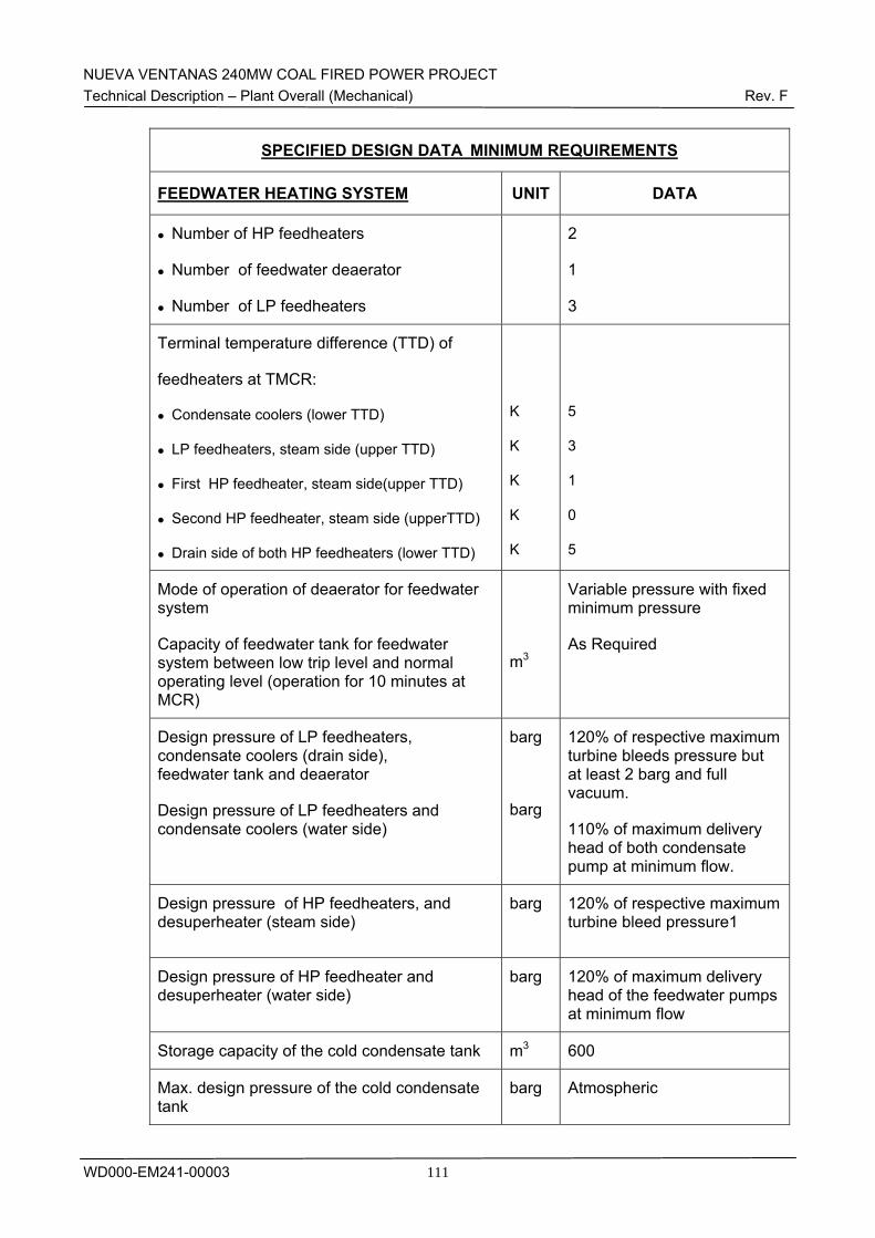
NUEVA VENTANAS 240MW COAL FIRED POWER PROJECT Technical Description – Plant Overall (Mechanical) Rev. F
WD000-EM241-00003
111
SPECIFIED DESIGN DATA MINIMUM REQUIREMENTS
FEEDWATER HEATING SYSTEM UNIT DATA
Number of HP feedheaters
Number of feedwater deaerator
Number of LP feedheaters
2
1
3
Terminal temperature difference (TTD) of
feedheaters at TMCR:
Condensate coolers (lower TTD)
LP feedheaters, steam side (upper TTD)
First HP feedheater, steam side(upper TTD)
Second HP feedheater, steam side (upperTTD)
Drain side of both HP feedheaters (lower TTD)
K
K
K
K
K
5
3
1
0
5
Mode of operation of deaerator for feedwater system
Capacity of feedwater tank for feedwater system between low trip level and normal operating level (operation for 10 minutes at MCR)
m3
Variable pressure with fixed minimum pressure
As Required
Design pressure of LP feedheaters, condensate coolers (drain side), feedwater tank and deaerator
Design pressure of LP feedheaters and condensate coolers (water side)
barg
barg
120% of respective maximum turbine bleeds pressure but at least 2 barg and full vacuum.
110% of maximum delivery head of both condensate pump at minimum flow.
Design pressure of HP feedheaters, and desuperheater (steam side)
barg
120% of respective maximum turbine bleed pressure1
Design pressure of HP feedheater and desuperheater (water side)
barg
120% of maximum delivery head of the feedwater pumps at minimum flow
Storage capacity of the cold condensate tank m3 600
Max. design pressure of the cold condensate tank
barg Atmospheric
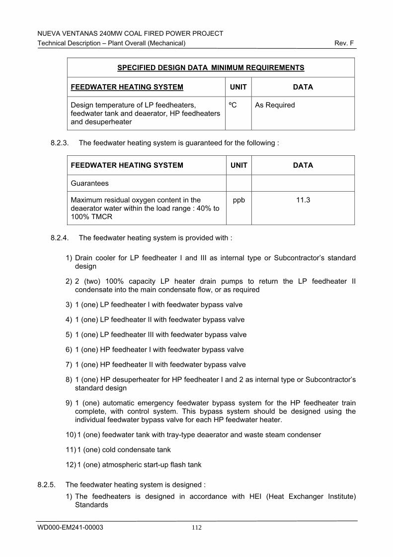
NUEVA VENTANAS 240MW COAL FIRED POWER PROJECT Technical Description – Plant Overall (Mechanical) Rev. F
WD000-EM241-00003
112
SPECIFIED DESIGN DATA MINIMUM REQUIREMENTS
FEEDWATER HEATING SYSTEM UNIT DATA
Design temperature of LP feedheaters, feedwater tank and deaerator, HP feedheaters and desuperheater
ºC As Required
8.2.3. The feedwater heating system is guaranteed for the following :
FEEDWATER HEATING SYSTEM UNIT DATA
Guarantees
Maximum residual oxygen content in the deaerator water within the load range : 40% to 100% TMCR
ppb 11.3
8.2.4. The feedwater heating system is provided with :
1) Drain cooler for LP feedheater I and III as internal type or Subcontractor’s standard
design
2) 2 (two) 100% capacity LP heater drain pumps to return the LP feedheater II condensate into the main condensate flow, or as required
3) 1 (one) LP feedheater I with feedwater bypass valve
4) 1 (one) LP feedheater II with feedwater bypass valve
5) 1 (one) LP feedheater III with feedwater bypass valve
6) 1 (one) HP feedheater I with feedwater bypass valve
7) 1 (one) HP feedheater II with feedwater bypass valve
8) 1 (one) HP desuperheater for HP feedheater I and 2 as internal type or Subcontractor’s standard design
9) 1 (one) automatic emergency feedwater bypass system for the HP feedheater train complete, with control system. This bypass system should be designed using the individual feedwater bypass valve for each HP feedwater heater.
10) 1 (one) feedwater tank with tray-type deaerator and waste steam condenser
11) 1 (one) cold condensate tank
12) 1 (one) atmospheric start-up flash tank 8.2.5. The feedwater heating system is designed :
1) The feedheaters is designed in accordance with HEI (Heat Exchanger Institute) Standards
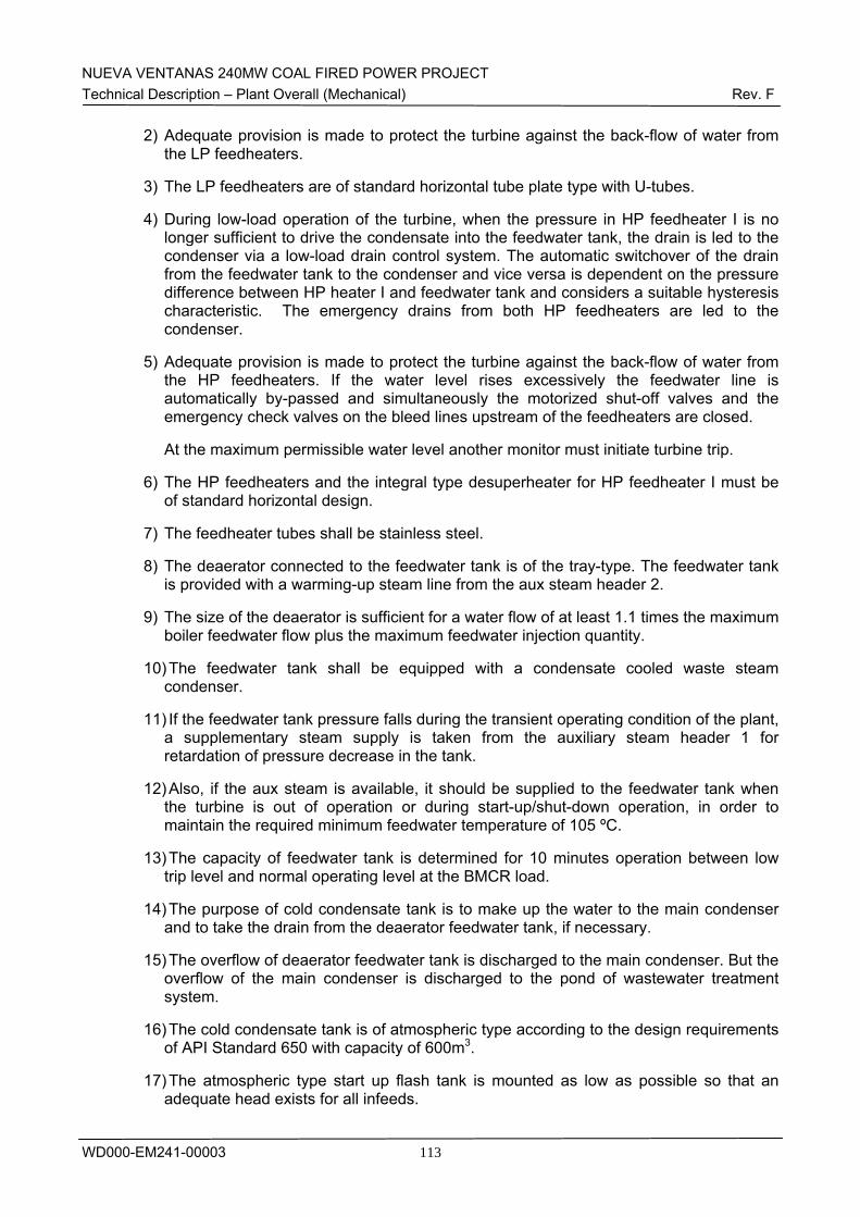
NUEVA VENTANAS 240MW COAL FIRED POWER PROJECT Technical Description – Plant Overall (Mechanical) Rev. F
WD000-EM241-00003
113
2) Adequate provision is made to protect the turbine against the back-flow of water from the LP feedheaters.
3) The LP feedheaters are of standard horizontal tube plate type with U-tubes.
4) During low-load operation of the turbine, when the pressure in HP feedheater I is no longer sufficient to drive the condensate into the feedwater tank, the drain is led to the condenser via a low-load drain control system. The automatic switchover of the drain from the feedwater tank to the condenser and vice versa is dependent on the pressure difference between HP heater I and feedwater tank and considers a suitable hysteresis characteristic. The emergency drains from both HP feedheaters are led to the condenser.
5) Adequate provision is made to protect the turbine against the back-flow of water from the HP feedheaters. If the water level rises excessively the feedwater line is automatically by-passed and simultaneously the motorized shut-off valves and the emergency check valves on the bleed lines upstream of the feedheaters are closed.
At the maximum permissible water level another monitor must initiate turbine trip.
6) The HP feedheaters and the integral type desuperheater for HP feedheater I must be of standard horizontal design.
7) The feedheater tubes shall be stainless steel.
8) The deaerator connected to the feedwater tank is of the tray-type. The feedwater tank is provided with a warming-up steam line from the aux steam header 2.
9) The size of the deaerator is sufficient for a water flow of at least 1.1 times the maximum boiler feedwater flow plus the maximum feedwater injection quantity.
10) The feedwater tank shall be equipped with a condensate cooled waste steam condenser.
11) If the feedwater tank pressure falls during the transient operating condition of the plant, a supplementary steam supply is taken from the auxiliary steam header 1 for retardation of pressure decrease in the tank.
12) Also, if the aux steam is available, it should be supplied to the feedwater tank when the turbine is out of operation or during start-up/shut-down operation, in order to maintain the required minimum feedwater temperature of 105 ºC.
13) The capacity of feedwater tank is determined for 10 minutes operation between low trip level and normal operating level at the BMCR load.
14) The purpose of cold condensate tank is to make up the water to the main condenser and to take the drain from the deaerator feedwater tank, if necessary.
15) The overflow of deaerator feedwater tank is discharged to the main condenser. But the overflow of the main condenser is discharged to the pond of wastewater treatment system.
16) The cold condensate tank is of atmospheric type according to the design requirements of API Standard 650 with capacity of 600m3.
17) The atmospheric type start up flash tank is mounted as low as possible so that an adequate head exists for all infeeds.
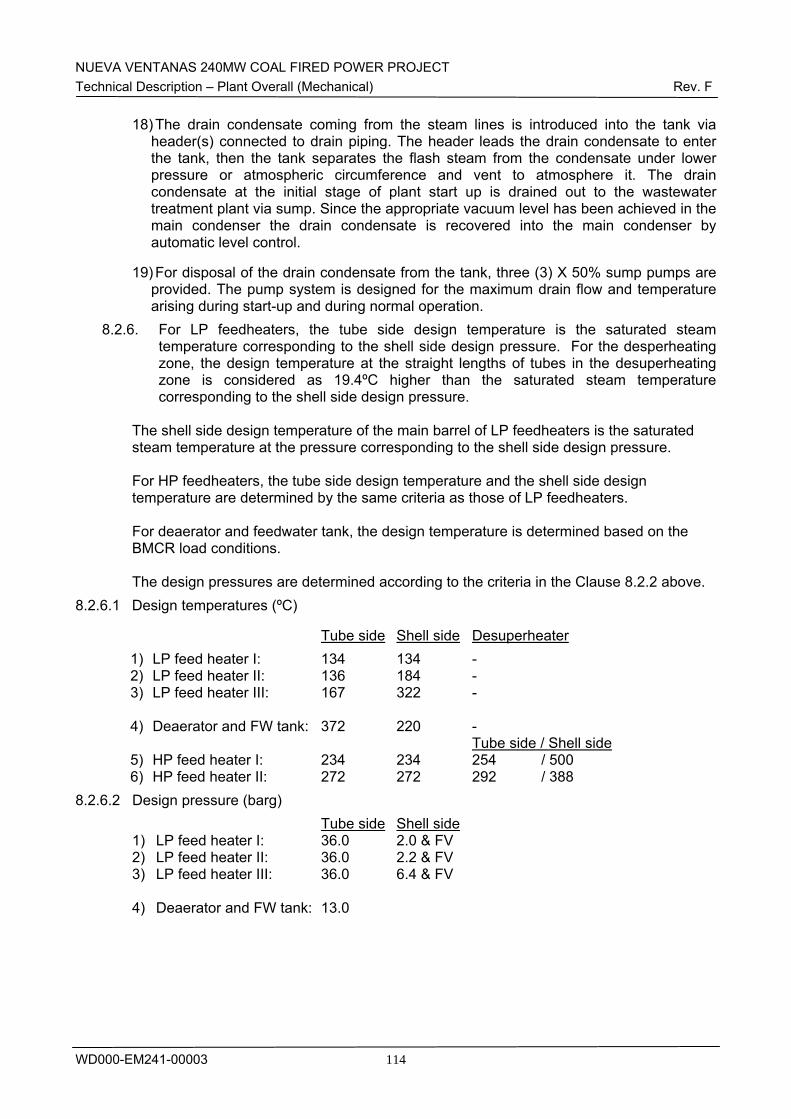
NUEVA VENTANAS 240MW COAL FIRED POWER PROJECT Technical Description – Plant Overall (Mechanical) Rev. F
WD000-EM241-00003
114
18) The drain condensate coming from the steam lines is introduced into the tank via header(s) connected to drain piping. The header leads the drain condensate to enter the tank, then the tank separates the flash steam from the condensate under lower pressure or atmospheric circumference and vent to atmosphere it. The drain condensate at the initial stage of plant start up is drained out to the wastewater treatment plant via sump. Since the appropriate vacuum level has been achieved in the main condenser the drain condensate is recovered into the main condenser by automatic level control.
19) For disposal of the drain condensate from the tank, three (3) X 50% sump pumps are provided. The pump system is designed for the maximum drain flow and temperature arising during start-up and during normal operation.
8.2.6. For LP feedheaters, the tube side design temperature is the saturated steam temperature corresponding to the shell side design pressure. For the desperheating zone, the design temperature at the straight lengths of tubes in the desuperheating zone is considered as 19.4ºC higher than the saturated steam temperature corresponding to the shell side design pressure.
The shell side design temperature of the main barrel of LP feedheaters is the saturated steam temperature at the pressure corresponding to the shell side design pressure. For HP feedheaters, the tube side design temperature and the shell side design temperature are determined by the same criteria as those of LP feedheaters. For deaerator and feedwater tank, the design temperature is determined based on the BMCR load conditions. The design pressures are determined according to the criteria in the Clause 8.2.2 above.
8.2.6.1 Design temperatures (ºC)
Tube side Shell side Desuperheater 1) LP feed heater I: 134 134 - 2) LP feed heater II: 136 184 - 3) LP feed heater III: 167 322 - 4) Deaerator and FW tank: 372 220 -
Tube side / Shell side 5) HP feed heater I: 234 234 254 / 500 6) HP feed heater II: 272 272 292 / 388
8.2.6.2 Design pressure (barg) Tube side Shell side
1) LP feed heater I: 36.0 2.0 & FV 2) LP feed heater II: 36.0 2.2 & FV 3) LP feed heater III: 36.0 6.4 & FV 4) Deaerator and FW tank: 13.0
NUEVA VENTANAS 240MW COAL FIRED POWER PROJECT Technical Description – Plant Overall (Mechanical) Rev. F
WD000-EM241-00003
115
5) HP feed heater I: 312 29.2 & FV 6) HP feed heater II: 312 56.0 & FV
8.3 Description
8.3.1. General description The feedwater heating system includes three (3) LP feed heaters, one (1) deaerator with feedwater tank, and two (2) HP feed heaters. These feedwater heaters with the following features will be supplied by Bumwoo engineering Co., Ltd. LP feedwater heater I
Type : two(2) zone, U-tube, horizontal S/N : 07SK001-01
LP feedwater heater II
Type : one(1) zone, U-tube, horizontal S/N : 07SK001-02
LP feedwater heater III
Type : two(2) zone, U-tube, horizontal S/N : 07SK001-03
HP feedwater heater I
Type : three(3) zone, U-tube, horizontal S/N : 07SK001-04
HP feedwater heater II
Type : three(3) zone, U-tube, horizontal S/N : 07SK001-05
Deaerator and feedwater tank with the following features will be supplied by Bumwoo engineering Co.,ltd.
Type : tray and spray S/N : 07SK001-008
LP feed heater I is installed in the transition area above tube bundle of the main condenser. Two (2) LP turbine extraction steam lines are routed and connected to the header in the transition area of the main condenser, and connected with the LP feed heater I shell side by three (3) outlet branches from the header. LP feed heater II is installed on the mezzanine floor of the ST building (FL+6,000). One (1) LP turbine extraction line is routed and divided into two (2) lines to connect with the LP feed heater II shell side. LP feed heater III is installed on the mezzanine floor of the ST building (FL+6,000). One (1) IP turbine exhaust line is routed to connect with the LP feed heater III shell side. One (1) x 100% deaerator and feedwater tank with 150 m3 storage capacity is located on the deaerator floor (FL+22.400m) above the feedwater pump station at the east side of ST building.
NUEVA VENTANAS 240MW COAL FIRED POWER PROJECT Technical Description – Plant Overall (Mechanical) Rev. F
WD000-EM241-00003
116
HP feed heater I is installed on the operating floor of the ST building (FL+12,000). One (1) IP turbine inter-stage extraction line is routed to connect with the HP feed heater I shell side. HP feed heater II is installed on the operating floor of the ST building (FL+12,000). HP turbine extraction line, which is branched off from the cold reheat line, is routed to connect with the HP feed heater II shell side. Two (2) x 100% LP heater drain pumps are installed on the pit floor near the condenser and condensate extraction pumps (CEP) in the ST building (FL. –2,500).
One (1) LP heater drain tank is installed on the drain line from LP FWH II underneath the mezzanine floor (FL. + 6,000). 1) LP feed heaters
The LP feed heaters are of the horizontal, shell and tube type. The tube material is stainless steel.
2) Deaerator and feedwater tank
The deaerator and feedwater tank is of the horizontal straight cylindrical type made of fabricated welded carbon steel plates. The deaerator is of the spray and tray type with its spray nozzles located on top of the deaerator. The deaerator and feedwater tank is equipped with the necessary connections for receiving condensate and chemicals, and distribution facilities for direct-contact heating by steam and for the reception of return flows from the minimum flow device of the boiler feed pumps. The heating steam is distributed into the deaerator shell. The steam path in the deaerator and its internals which is subjected to the flow of undeaerated or partially deaerated water are made of stainless steel of adequate quality to withstand corrosion. The oxygen concentration of the water in the feedwater tank after deaerated is controlled not to exceed 7 ppb during the Plant normal operation. The deaerator is equipped with a safety valve for protection against high pressure and vent piping with silencer. The feed water tank is provided with overflow and drain.
2) HP feed heaters (32LAD10AC001 and -20AC001)
The HP feed heaters are of the horizontal, shell and tube type. The tube material is stainless steel.
3) LP heater drain pumps (32LCJ20AP001 and -20AP002)
The LP heater drain pumps are of the horizontal, centrifugal type.
4) LP heater drain tank (32LCC20BB001)
A LP heater drain tank is installed on the mezzanine floor to ensure the sufficient NPSH available of the LP drain pump. A condensate filling line (DN25) is provided upstream of the pump suction for cooling the drain from LP feed heater II if the drain
NUEVA VENTANAS 240MW COAL FIRED POWER PROJECT Technical Description – Plant Overall (Mechanical) Rev. F
WD000-EM241-00003
117
temperature is higher than the value which is preset for keeping the required NPSH available.
The drain and vent system are designed in accordance with the requirements of ASME TDP-1 for prevention of water induction to turbine. The pipeworks of the feedwater heating system are shown in the P&I diagrams of : - FWH extraction steam system (1/2) and (2/2) (Drawing No. WD330-EM103-00004 and
-00005). - FWH vent and drain system (1/2) and (2/2) (Drawing No. WD330-EM103-00006 and -
00007).
8.3.2. System Operation and Control
1) The normal drain from the LP feedheater I is discharged to the condenser.
2) The emergency drains from the LP feedheater II and III are discharged to the condenser.
3) The normal drains from the LP feedheater II are returned to the main condensate line by the LP heater drain pumps.
4) The normal drains from LP feedheater III is drained to shell side of LP feedheater II.
5) The water in the LP heater drain tank is cooled by mixing the condensate from the valve sealing water (condensate) delivery line in order to maintain sufficient NPSH available for LP heater drain pumps as necessary.
6) The feedwater tank level is controlled by throttling the level control valve (LCV, 32LCA70AA071) located on the condensate line upstream of the deaerator.
7) The deaerator pressure is maintained normally according to the IP turbine interstage extraction pressure, but abnormally the pressure may be maintained at the pressure corresponding to the turbine load by throttling the pressure control valve (PCV, 32LBG47AA071) located upstream of deaerator on the auxiliary steam line from the aux steam header 1.
8) If the feedwater tank pressure falls during the transient operation of the plant, a supplementary steam is supplied from the auxiliary steam header 1 for maintaining the required minimum steam pressure in the deaerator and feedwater tank.
9) Also, if the aux steam is available, it should be supplied to the feedwater tank when the turbine is out of operation or during start-up/shut-down operation, in order to maintain the required minimum feedwater temperature of 105 ºC.
10) The drain from the deaerator feedwater tank is discharged into the cold condensate tank.
11) The overflow of deaerator feedwater tank is discharged to the main condenser. And the overflow of the main condenser is discharged to the pond of wastewater treatment system.
12) The normal drains from the HP feedheater I and II are discharged to the deaerator.
13) During low-load operation of the turbine, when the pressure in HP feedheater I is no longer sufficient to drive the condensate into the feedwater tank, the drain is led to the
NUEVA VENTANAS 240MW COAL FIRED POWER PROJECT Technical Description – Plant Overall (Mechanical) Rev. F
WD000-EM241-00003
118
condenser via a low-load drain control system. The automatic switchover of the drain from the feedwater tank to the condenser and vice versa is dependent on the pressure difference between HP heater I and feedwater tank and considers a suitable hysteresis characteristic.
14) The emergency drains from both HP feedheater I and II are led to the condenser.
15) In order to protect the turbine against the back-flow of water from the HP feedheaters, the feedwater line is automatically by-passed if the water level rises excessively, and simultaneously the motorized shut-off valves and the emergency check valves on the bleed lines upstream of the feedheaters are closed.
At the maximum permissible water level another monitor must initiate turbine trip.
8.4 Operation Principle
8.4.1. Preparation
Condensate system in operation Feedwater system in operation
STG in operation
Closed cooling water system in operation
8.4.2. Start-up and Shutdown The deaerator should be placed into service as soon as sufficient heating steam is available. The deaerator is placed into service by admitting warming steam from the Auxiliary Steam System. Once the deaerator has been stabilized, the continuous vent is adjusted as required for proper feedwater deaeration. If warming steam is unavailable at unit start-up, deaeration is provided by oxygen scavenger injection (Refer to Chemical Treatment System Description). Prior to admitting steam to the turbine, all extraction line drain valves should be verified automatically opened. Below 15% turbine load, the extraction line drain valves should be open. Automatic heater level may be unstable at low loads and require temporary operation in manual. At start-up, the start-up vent line and continuous vent line for high pressure feedwater heater should be open to the deaerator and such vent line for low pressure feedwater heater to the condenser flash vessel. The deaerator startup vents should be opened to atmosphere and the normal vent to the atmosphere should be opened to its normal run position (to be determined by operation).
As the unit increases above 25% load, all start-up vents are closed. All continuous vents remain open with the high pressure feedwater heaters continuously venting to the
NUEVA VENTANAS 240MW COAL FIRED POWER PROJECT Technical Description – Plant Overall (Mechanical) Rev. F
WD000-EM241-00003
119
deaerator, the low pressure feedwater heaters continuously venting to the condenser flash vessel; and the deaerator continuously venting to atmosphere. During normal operation, steam flows from the turbine extractions to the feedwater heaters and deaerator through fully opened extraction line power-assisted check valves and extraction isolation valves. The extraction line drain valves automatically close as turbine load increases above 15%. Feedwater heater level controls are in automatic with level steady and drain flow out of the normal control valves. Especially, if level of LP feedwater heater II and LP heater drain tank is maintained steadily as normal level, one (1) unit of LP heater drain pump is started through minimum recirculation line and is controlled by discharge control valve. All relief valves should be free to move with no restriction of movement due to outside interference (chains, boards, wires, tags, etc.).
8.4.3. Operation, Closed and Open Loop controls
Valve 별로 구분하지 말고 주요 Protection Logic 별로 구분바람. 예) - Heater start-up 절차 including Warming-up - Heater level control (각 Level별 Action 확인) LL L - Alarm H – Alarm, other drain HH-Extraction isolation등등 - 1) HP feedwater heater II
Extraction Line Check Valve (32LBQ20AA061)
In case of high-high level of feedwater heater or turbine trip, this valve will be closed.
Extraction Line Shutoff Valve (32LBQ20AA041) The extraction line shutoff valve is automatically positioned by the DCS operator’s station. The operator can position the valve at any point between full open and full close. The shutoff valve closes for HP feedwater heater II experiencing a high-high level indication for turbine water induction protection.
Normal Drain Control Valve (32LCH31AA071) The control valve is automatically modulated by the DCS as required to maintain proper heater water level (32LAD20CL101A/B/C). If desired, the control valve can also be manually positioned from the DCS operator’s station. The valve closes on high-high level in HP Feedwater heater I. The valve fails closed.
Emergency Drain Control Valve (32LCH40AA071)
NUEVA VENTANAS 240MW COAL FIRED POWER PROJECT Technical Description – Plant Overall (Mechanical) Rev. F
WD000-EM241-00003
120
The control valve is automatically modulated by the DCS as required to maintain proper heater water level when an emergency level is indicated ((32LAD20CL101A/B/C). If desired, the control valve can also be manually positioned from the DCS operator’s station, but will transfer the controls to auto upon high level. The valve fails open.
Motorized Feedwater Bypass & Isolation Valves (32LAB60AA041/042/841) In case of high-high level of HP Feedwater heater II, motorized isolation valves (32LAB60AA041/042) are closed and motorized bypass valve(32LAB60AA841) is open.
2) HP feedwater heater I
Extraction Line Check Valves (32LBQ10AA061/062) In case of high-high level of HP FWH heater I or turbine trip, this valve will be closed.
Extraction Line Shutoff Valve (32LBQ10AA461/2) The extraction line shutoff valve is automatically positioned by the DCS operator’s station. The operator can position the valve at any point between full open and full close. The shutoff valve closes for HP feedwater heater I experiencing a high-high level indication for turbine water induction protection.
Extraction Line drain Valves (32LBQ10AA061/062) The extraction line drain valves are automatically positioned by the DCS operator’s station. The valves are open at start-up and turbine trip and closes automatically at 15% or greater load. This function overrides manual positioning of the valves. The valves fail open.
Normal Drain Control Valve (32LCH11AA071) The control valve is automatically modulated by the DCS as required to maintain proper heater water level (32LAD10CL101A/B/C). If desired, the control valve can also be manually positioned from the DCS operator’s station. The valve closes on high-high level in HP Feedwater heater I. The valve fails closed.
Emergency Drain Control Valve (32LCH20AA071) The control valve is automatically modulated by the DCS as required to maintain proper heater water level when an emergency level is indicated ((32LAD10CL101A/B/C). If desired, the control valve can also be manually positioned from the DCS operator’s station, but will transfer the controls to auto upon high level. The valve fails open. If pressure difference between shell of HP feedwater heater I and deaerator is lower than predetermined valve, which is larger than static head between them, this valve will be open.
Motorized Feedwater Bypass & Isolation Valves (32LAB50AA041/042/841) In case of high-high level of HP Feedwater heater I, motorized isolation valves (32LAB50AA041/042) are closed and motorized bypass valve(32LAB50AA841) is open.
3) Deaerator & Feedwater tank
NUEVA VENTANAS 240MW COAL FIRED POWER PROJECT Technical Description – Plant Overall (Mechanical) Rev. F
WD000-EM241-00003
121
Feedwater Tank Overflow Control Valve (32LCK10AA441) The Deaerator control valve is automatically modulated by the DCS on high high Deaerator level to prevent Turbine water induction. The Deaerator overflow control discharges to the Condenser hotwell. If desired, the control valve can also be manually positioned from the DCS operator’s station, but will transfer the controls to auto upon high level. The valve fails open.
Extraction Line Shutoff Valve (32LBD10AA041) The extraction line isolation valve is automatically positioned by the DCS operator’s station. The operator can position the valve at any point between full open and full close. The isolation valve closes for the deaerator experiencing a high-high level for turbine water induction protection.
Extraction Line Check Valves (32LBD10AA061/062) Upon turbine trip, these valves for turbine overspeed protection. The valve fails open.
Extraction Line drain Valves (32LBD10AA462) The extraction line drain valves are automatically positioned by the DCS operator’s station. The valves are open at start-up and turbine trip and closes automatically at 15% or greater load. This function overrides manual positioning of the valves. The valves fail open.
Deaerator Pegging Control Valve (32LBG47AA071) Deaerator pegging control valve will open in case of turbine trip for BFP protection against pressure decay. Prior to start-up, this valve will be used to warm-up feedwater temperature.
4) LP feedwater heater III
Extraction Line Check Valves (32LBS30AA061) In case of high-high level of LP FWH III or turbine trip, this valve will be closed.
Extraction Line Shutoff Valve (32LBS30AA041) The extraction line shutoff valve is automatically positioned by the DCS operator’s station. The operator can position the valve at any point between full open and full close. The shutoff valve closes for LP feedwater heater III experiencing a high-high level indication for turbine water induction protection.
Extraction Line Drain Valves (32LBS30AA461/462) The extraction line drain valves are automatically positioned by the DCS operator’s station. The valves are open at start-up and turbine trip and closes automatically at 15% or greater load. This function overrides manual positioning of the valves. The valves fail open.
Normal Drain Control Valve (32LCJ60AA071) The control valve is automatically modulated by the DCS as required to maintain proper heater water level (32LCC20CL101A/B/C). If desired, the control valve can
NUEVA VENTANAS 240MW COAL FIRED POWER PROJECT Technical Description – Plant Overall (Mechanical) Rev. F
WD000-EM241-00003
122
also be manually positioned from the DCS operator’s station. The valve closes on high-high level in LP Feedwater heater II. The valve fails closed.
Emergency Drain Control Valve (32LCH40AA071) The control valve is automatically modulated by the DCS as required to maintain proper heater water level when an emergency level is indicated ((32LCC30CL101A/B/C). If desired, the control valve can also be manually positioned from the DCS operator’s station, but will transfer the controls to auto upon high level. The valve fails open.
5) LP feedwater heater II
Extraction Line Check Valves (32LBS20AA061) In case of high-high level of LP FWH II or turbine trip, this valve will be closed.
Extraction Line Shutoff Valve (32LBS20AA041) The extraction line shutoff valve is automatically positioned by the DCS operator’s station. The operator can position the valve at any point between full open and full close. The shutoff valve closes for LP feedwater heater II experiencing a high-high level indication for turbine water induction protection.
Extraction Line Drain Valves (32LBS20AA461/462) The extraction line drain valves are automatically positioned by the DCS operator’s station. The valves are open at start-up and turbine trip and closes automatically at 15% or greater load. This function overrides manual positioning of the valves. The valves fail open.
LP Heater Drain Tank Level Control Valve (32LCJ30AA071) The control valve is automatically modulated by the DCS as required to maintain proper heater water level (32LCC20CL101A/B/C). If desired, the control valve can also be manually positioned from the DCS operator’s station. The valve closes on high-high level in deaerator feedwater tank. The valve fails closed.
Emergency Drain Control Valve (32LCJ50AA071) The control valve is automatically modulated by the DCS as required to maintain proper heater water level when an emergency level is indicated ((32LCC20CL101A/B/C). If desired, the control valve can also be manually positioned from the DCS operator’s station, but will transfer the controls to auto upon high level. The valve fails open.
Minimum Recirculation Shut-off Valve (32LCJ42AA071) The Shut-off valve is automatically turned on and off by discharge flow rate (32LCJ30CF001) as required to maintain proper flow rate of LP heater drain pump higher than its minimum flow rate when an emergency level is indicated ((32LAD20CL101A/B/C). The valve fails closed.
6) LP feedwater heater I
NUEVA VENTANAS 240MW COAL FIRED POWER PROJECT Technical Description – Plant Overall (Mechanical) Rev. F
WD000-EM241-00003
123
Normal Drain Control Valve (32LCJ11AA071) The control valve is automatically modulated by the DCS as required to maintain proper heater water level (32LCC10CL101A/B/C). If desired, the control valve can also be manually positioned from the DCS operator’s station. The valve fails closed.
Emergency Drain Control Valve (32LCJ13AA071) The control valve is automatically modulated by the DCS as required to maintain proper heater water level when an emergency level is indicated ((32LAC10CL101A/B/C). If desired, the control valve can also be manually positioned from the DCS operator’s station, but will transfer the controls to auto upon high level. The valve fails open.
Motorized Feedwater Bypass & Isolation Valves (32LCA40AA041/042/841) In case of high-high level of LP Feedwater heater I, motorized isolation valves (32 LCA40AA041/042) are closed and motorized bypass valve(32 LCA40AA841) is open.
8.5 Reference
P&ID : FWH Extraction System, WD310-EM103-00004/5 FWH Vent and Drain System, WD310-EM103-00006/7 Feedwater System (2/2), WD330-EM103-00002 Condensate System (3/3), WD320-EM103-00003
Control logic diagram
9. CONDENSER AND CONDENSATE SYSTEM (4.7, 4.11)
9.1 Function
The functions of the condenser and condensate system are : to deliver the condensate from the surface condenser hotwell to deaerator via the
SJAE condenser, gland steam condenser and LP feedheaters (I, II and III). to supply the condensate for :
- LP turbine exhaust hood spray, - Condenser flash vessel spray, - Start-up flash tank spray, - Valve sealing, - Gland steam desuperheater, - Aux steam system desuperheating, - CCW head tank make-up, - Chemical dosing system make-up, - Drain cooling upstream of LP heater drain pump
NUEVA VENTANAS 240MW COAL FIRED POWER PROJECT Technical Description – Plant Overall (Mechanical) Rev. F
WD000-EM241-00003
124
9.2 Design Bases The condenser and condensate system is designed with the following design bases :
9.2.1. Codes and Standards The condenser and condensate system design is based on the criteria set forth in the following codes and standards :
ASME Boiler and Pressure Vessel Code – Section VIII ASME B31.1 Power Piping ASME TDP – 1 Recommended Practices HEI Heat Exchange Institute Standards HI Hydraulic Institute Standards Manufacturer’s design criteria and practices
And other applicable international cods and standards 9.2.2. The condenser and condensate system are provided with:
The condensate system is from the condenser to the inlet of deaerator with feedwater tank. 1) 1 (one) condenser with condenser flash vessel (box), including titanium tubes, sealing
water system, vacuum breaker, automatic venting of the cooling water chambers at outage of cooling water pumps
2) Steam jet air ejectors of 2 (two) 100% ejectors for normal operation and 1 (one) hogging ejector for start-up.
3) 2 (two) x 100% condensate extraction pumps complete with motor drive and minimum flow device
4) Separate corrosion protection system covering the main condenser as an impressed current cathodic protection system
5) 1 (one) x 100% gland steam condenser is capable of removing the condensation heat of the gland steam which is separated from the steam turbine.
9.2.3. The condenser and condensate system are designed : 1) The surface condenser is designed in accordance with the HEI standards.
2) In dimensioning the heat exchanger surfaces it is assumed that all the load cases are met even if 10% of the condenser tubes are blocked. Under-cooling of the condensate is avoided. The pressure design on the steam side must at least cover the range from full vacuum to 1 bar gauge and, on the water side from full vacuum to 3 bar gauge.
3) The water side of the condenser is operated on the single pass system and is divided into two independent halves. Each half is so dimensioned that the turbine generator can be operated with correspondingly decreased load while the other half is out of action. The tube plates are made of Titanium or Titanium clad.
4) Each half of the water chamber contains venting and water drain connections of adequate size. Sufficient and automatically actuated venting at the cooling water side in case of sudden outage of the main cooling water pumps is provided. The water side of the condenser is designed so that satisfactory functioning of the debris filter equipment is ensured.
5) The water boxes are made of carbon steel with at least 3 mm rubber lining
6) The maximum static head between the highest point (center of condenser top tube) in
NUEVA VENTANAS 240MW COAL FIRED POWER PROJECT Technical Description – Plant Overall (Mechanical) Rev. F
WD000-EM241-00003
125
the main cooling water system and the seal pit should not exceed 8 m.
7) In addition, the condenser is suitable for accepting all drains occurring during start-up or operation.
8) The capacity of the condenser hotwell corresponds to a condensate flow of at least 2.5 minutes at TMCR.
9) The surface condenser is sized to maintain the vacuum of 0.04 bara at a design cooling (sea) water temperature of 15 . The temperature rise of the circulating water ℃in the surface condenser is 7.6 at the design condition.℃
10) The condensate extraction pump suction head is the sum of the condenser full vacuum plus the static head from the condenser water level to the pump nozzle center line minus the suction strainer loss and piping friction losses, including 10% margin, between condenser and pump inlet at pump rated capacity.
11) The pump discharge head is the sum of the 115% of deaerator operating pressure, deaerator spray nozzle losses, LP heater losses, piping losses from pump discharge to deaerator including 10% margin, losses of level control valve (LCV 32LCA70AA071) and flow meter (FE 32LCA40CF001), losses of SJAE condenser and GSC, LP FWH I, II and III, and static head from the pump nozzle center line to deaerator inlet nozzles.
12) The capacity of steam jet air ejector system is such that a vacuum of 0.3 bar abs. for start-up of the steam turbine is achieved within approx. 30 minutes.
9.2.4. The design flow rate of condensate extraction pumps is sized to cover the condensate requirements on the basis of Heat Balance for the BMCR load at reference conditions.
9.2.5. The velocities in the condensate delivery lines during full load operation are in the range
of 1.8 to 3.0 m/s.
The condensate system piping and valves have a design pressure determined by the condensate pump shutoff pressure. The max. allowable pressure of the system is 33barg which is the shut-off head of condensate extraction pump. The system design pressure is 33barg. The normal operating temperature of the condensate system is 29.5℃. The design temperature is 90 ℃.
9.3 Description
9.3.1. General Description
The condensate system is from the condenser to the inlet of deaerator with feedwater tank.
The condensate system includes one (1) main condenser, one (1) steam jet air ejector system with inter-after condenser, two (2) condensate extraction pumps, one (1) gland steam condenser, one (1) cold condensate tank, two (2) condensate make-up pumps, , associated piping, valves, instrumentation, etc.
One (1) x 100% main condenser is located on the ground floor (FL+0.000) in the ST building. The condenser heat duty is 1,121 x 106 kJ/h. The condenser is connected to the LP turbine exhaust hood end under the LP turbine, and is installed perpendicular to the STG axes.
NUEVA VENTANAS 240MW COAL FIRED POWER PROJECT Technical Description – Plant Overall (Mechanical) Rev. F
WD000-EM241-00003
126
The condenser is provided with an air removal system to maintain the condenser vacuum in all operation conditions, and to achieve the vacuum rapidly during start-up, which comprises steam jet air ejectors of two (2) 100% ejectors for normal operation and one (1) hogging ejector for start-up, including inter and after condenser, and is located on the mezzanine floor of the ST building (FL+6,000).
The condenser is provided with an impressed current cathodic protection system as separate corrosion protection system. Two(2) x 100% condensate extraction pumps are located on the pit floor (FL-3,000) of ground floor in the ST building. The pump capacity is 630 m3/h at 260m total head, each. One (1) is in normal operation, and the remaining one (1) is on standby. One (1) x 100% gland steam condenser is located on the mezzanine floor of the ST building (FL+6,000).
The gland steam condenser is installed for recovering the condensation heat of the gland steam which is leaked from the steam turbine. Steam leaking past the turbine glands is utilised for heating condensate water in a gland steam condenser. The gland steam condenser drainage is led to the main condenser.
The condensate is delivered by means of two (2) x 100% condensate extraction pumps from the main condenser hotwell to the deaerator via the following equipment, such as :
SJAE condenser Gland steam condenser LP feedheater I LP feedheater II LP feedheater III
The condensate also is delivered to the various equipment and system, such as : LP turbine exhaust hood spray Condenser flash vessel spray Start-up flash tank spray Valve sealing Gland steam desuperheater Aux steam system desuperheating CCW head tank make-up Chemical dosing system make-up Drain cooling upstream of LP heater drain pump
The LP heater drain from LP heater II is delivered into the main condensate line upstream of LP heater III by the LP heater drain pumps.
For safe operation of LP heater drain pumps, LP drain tank is installed between LP feedheater II and LP drain tank suction line.
The condensate system is provided with a recirculation line to protect the pump from overheating or instability at low pump flow.
The condensate system is provided with an overflow line to discharge the condensate to the abnormal waste water pond when reaches the condenser hotwell level high.
A sampling line and chemical injection line (for dosing of Ammonia) are provided on the condensate delivery line downstream of the condensate pumps.
Condensate make-up system includes one (1) cold condensate tank and two (2) x 100% condensate make-up pumps with bypass line.
NUEVA VENTANAS 240MW COAL FIRED POWER PROJECT Technical Description – Plant Overall (Mechanical) Rev. F
WD000-EM241-00003
127
The cold condensate tank of 600m3 is located outside of the ST building. The cold condensate tank is filled by the demineralised water pumps which are installed near the demineralised water tank (1,800m3).
The condensate make-up pumps (2x100%) are located near the cold condensate tank. The pump capacity is 40 m3/h at 42m total head, each.
Initial water filling to the deaerator can be made using the demineralised water pumps for cold start-up of the Plant, if necessary.
The pipeworks of the condensate system are shown in the P&I diagrams of condensate system (1/3, 2/3, 3/3) (Drawing No. WD320-EM103-00001 to 00003).
1) Main condenser
The condenser with the following features will be supplied by Bumwoo engineering Co. Ltd. Type : Surface Condenser S/N : 07PC002-01
The main condenser is of the surface, single-shell, one-pass type which is divided into two (2) halves with tube and tube sheets fitted with a flash vessel. The flash vessel for the surface condenser is provided to avoid any impingement directly upon the main condenser tube.
The tube plates are made of Titanium or Titanium clad.
The surface condenser is sized to maintain the vacuum of 0.04 bara at a design cooling (sea) water temperature of 15 . The temperature rise of the circ℃ ulating water in the surface condenser is 7.6 at the design condition.℃
The main condenser provides a heat sink of adequate capacity to condensate the exhaust steam coming from the steam turbine. The heat from this main condenser is rejected to seawater.
The condenser hotwell capacity of 30m3 is sized for a minimum of 2.5 minutes condensate for TMCR between normal water level and low trip level.
The condensate stored in the condenser hotwell is sufficient to deliver the condensate to the deaerator using the condensate extraction pumps during any transient condition.
2) Condensate extraction pumps
The condensate extraction pumps with the following features will be supplied by Hyundai heavy industries, Co. Ltd. Type : Centrifugal, Vertical, Can Model : 500X300VWDB6M
The condensate extraction pumps are of centrifugal, vertical canned type, and take their suction from the condenser hotwell. Then the pump delivers the condensate to the deaerator through the steam jet air ejector (SJAE) condenser, gland steam condenser (GSC), LP feed heater I, II and III.
The condensate extraction pumps with electric motor are used to deliver the required quantity of water to satisfy the condensate water requirements under the various operating conditions of steam cycle.
NUEVA VENTANAS 240MW COAL FIRED POWER PROJECT Technical Description – Plant Overall (Mechanical) Rev. F
WD000-EM241-00003
128
A suction strainer with differential pressure switch and backwashing facility is fitted to each pump.
The condensate extraction pumps are provided with the seal water connections. The driving motors are of air-cooled type, and its speed is 1,500 rpm.
3) Air removal system
The steam jet air ejector system is provided for hogging and holding operation.
The air removal system function is to remove the air and the non-condensable gases from the condenser and to exhaust them to the atmosphere.
The air removal system consists of one (1) x 100% hogging steam jet air ejector for start-up operation and two (2) x 100% holding steam jet air ejectors for normal operation. The air removal system is provided with an inter and after condenser.
The capacity of steam jet air ejector system is such that a vacuum of 0.3 bar abs. for start-up of the steam turbine is achieved within approx. 30 minutes. This vacuum may also be attained in a slightly longer period in case that no sealing steam is supplied to the turbine shaft glands.
For these steam jet air ejectors, the auxiliary steam from aux steam header 1 (at 16barg, 270℃) is used for evacuating the entrained air or non-condensable gases from the inside of main condenser.
During start-up operation, a hogging steam jet air ejector in operation. During normal operation, one (1) holding SJAE is in operation and the remaining one (1) is on standby. The steam condensed in the SJAE condenser is cooled by the main condensate.
4) Gland steam condenser (GSC, supplied by turbine manufacturer)
One (1) x 100% gland steam condenser is capable of removing the condensation heat of the gland steam which is separated from the steam turbine.
5) Condensate make-up system
The cold condensate tank is of atmospheric, vertical, cylindrical type, which is designed in accordance with the requirements of API 650.
The condensate make-up water pumps are horizontal, centrifugal type.
9.3.2. System Operation and Control
1) Condenser
During start-up, normal operation, shutdown and trip of the Steam Turbine, the LP steam is exhausted into the condenser.
Before start-up of the condenser (admitting steam into the main condenser) the following criteria must be fulfilled :
Circulating water system is in operation
Main condenser hotwell and condensate system are normalized
Overflow from the main condenser when reaches the condenser hotwell level high, is led into the abnormal wastewater pond. An overflow control valve (LCV
NUEVA VENTANAS 240MW COAL FIRED POWER PROJECT Technical Description – Plant Overall (Mechanical) Rev. F
WD000-EM241-00003
129
32LCA34AA071) is provided on the main condensate line downstream of the gland steam condenser and is opened in case of condenser high level.
The condenser make-up system automatically maintains the proper amount of water in the condenser hotwell.
Normal condensate make-up into the condenser is provided from the cold condensate tank. It is automatically controlled by condenser hotwell level transmitter (LIT 32MAG10CL101A, -101B, -101C).
The water side of the condenser is operated on the single pass system and is divided into two (2) independent halves. Each half is so dimensioned that the turbine generator can be operated with correspondingly decreased load while the other half is out of operation.
By dividing the cooling water side into two (2) parallel flows and two (2) independent tube nests, the main condenser is capable of condensing at least more than 50% of the full load exhaust steam if one condenser half is out of operation for repair or maintenance works without exceeding the max allowable cooling water outlet temperature of 30℃ at the max. cooling water inlet temperature of 21℃ and triggering low vacuum unloading or alarm.
In case that one condenser half is out of operation, the expected maximum Plant load is approx. 90% of the full load exhaust steam without exceeding the cooling water outlet temperature of 30℃ at the inlet temperature of 15℃.
2) Condensate extraction pumps
During normal operation of the Plant, one (1) pump is operated in covering the required condensate water quantity to the deaerator. The remaining one (1) is on standby.
The condensate extraction pumps are operated with full automatic control during the Plant start-up, normal operation and shutdown time.
The standby pump is capable of automatically starting up within minimum available time upon failure of running pump.
The recirculation control valve (FCV, 32LCA35AA071) downstream of the gland steam condenser ensures the required minimum flow rate of the condensate extraction pumps to protect the pump by preventing an inadmissible warming up of the pump and evaporation of condensate in the pump, which could lead to cavitations.
The minimum flow control is executed by a flow measuring (FE, 32LCA40CF001), with transmitter, which automatically modulates a flow control valve to recirculate the condensate back to the hotwell when required according to the boiler load. During normal operation the condensate recirculation control valve is closed.
Permanent vent lines from each pump back to the condenser keep the suction sides vented.
For the first filling or a refilling after the piping system has been drained, the LP heater I inlet valves are closed, the pump suction and discharge isolation valves are open. The suction pipe and the CEP up to minimum recirculation valve is then filled through gravity flow and vented via permanent vent lines at each CEP back to the condenser.
For repairing one pump during unit operation, the corresponding pump isolation valves
NUEVA VENTANAS 240MW COAL FIRED POWER PROJECT Technical Description – Plant Overall (Mechanical) Rev. F
WD000-EM241-00003
130
have to be closed in following sequence:
1) Pump discharge isolation valve
2) Pump suction isolation valve
3) Pump vent valve in the vent line to condenser
4) Seal water isolating valve.
For refilling one pump after repairing, the seal water isolating valve has to be opened, then the permanent vent line of the running CEP has to be closed and the vent line of the repaired pump is opened and the pump will be evacuated. Then the suction isolation valve is opened while the discharge isolation valve is kept closed. Then the permanent vent line shall be opened again. When the pump system has been completely filled and vented, the discharge isolation valve can be opened.
3) Air removal system
One (1) hogging steam jet air ejector is in operation for hogging prior to start-up of the turbine during the Plant start-up. The hogging steam jet ejector is operated until the main condenser vacuum is reached to 0.3 bara from the atmosphere under hogging operation.
During normal operation of the Plant, two (2) holding steam jet air ejectors are used with one (1) unit in operation and the remaining one (1) on standby.
4) Condensate make-up system
During start-up operation of the Plant, one (1) condensate make-up pump is in operation, and the remaining one (1) is on standby. The condensate from the cold condensate tank can be made up through bypass line (DN150) during the Plant normal operation.
9.3.3. Start-up and Shutdown
Prior to start-up of the condensate extraction pumps the condenser hotwell is filled up to the start-up level by activating the hotwell level control and opening of the condensate make-up pump discharge level control valve. The discharge side must be filled and vented. The gland steam condenser inlet and outlet valves must be open and the bypass valve is closed. The pump minimum recirculation and condenser over flow control system are normalized. Then the pump can be started in minimum flow operation. The minimum flow is returned to the condenser hotwell.
If auxiliary steam system and condensate system is in operation, start hogging ejector opening motive steam shut-off valve(32LBG81AA061) and suction shut-off valve(32LDC22AA061) for hogging ejector to increase vacuum in condenser shell. After condenser vacuum reaches 0.3 bara, holding ejector is switched from hogging ejector with closing motive steam and suction shut-off valves for hogging ejector and opening motive steam shut-off valve(32LBG82AA061) and suction shut-off valve (32LDC21AA061).
9.3.4. Operation, Closed and Open Loop Controls
----- 각 주요 Control 및 Protection으로 구분할 것. 예) Condenser Hotwell level control Condenser HHWL dumping operation
NUEVA VENTANAS 240MW COAL FIRED POWER PROJECT Technical Description – Plant Overall (Mechanical) Rev. F
WD000-EM241-00003
131
CEP Minimum flow protection 등등 The control system activates the Condensate Extraction Pump and starts the pump upon receipt of start signal from Unit Coordination Program, if the following criteria are fulfilled:
• Closed Cooling Water System (PGA) IN OPERATION
• Demineralized Water Supply System (GHB) IN OPERATION
• Condenser Hotwell Level > MIN
• Condensate System Vent Release Confirmed by Operator
• CEP Discharge Pressure > MIN
Under normal operating conditions condensate is pumped by one (1) pump to the deaerator. The second pump will be switched on depending on CEP Discharge Pressure.
Reasons for a failure of a condensate extraction pump could be:
• SWGR fault INITIATE
• Motor Bearing Temp. > High High
• CEP Motor Winding Temp > MAX
• CEP Bearing Oil Temp > MAX
The Automatic switch over function will start the pump which is in stand by.
Condition for a trip off all Condensate Extraction Pumps could be:
• Condenser Level < Low
• Feedwater Storage Tank Level > high high
The condensate level in the condenser hotwell is controlled via:
Condenser Make-Up Water Valve (32LCP10AA071)
Condenser Overflow Valve (32LCA34AA071)
The condensate recirculation valve (FCV-32LCA35AA071) is controlled by the condensate flow measured by flow element (32LCA40CF001). During normal operation the condensate control valve is closed.
9.4 Reference
• P&ID : Condensate System (1/3), WD320-EM103-00001 • P&ID : Condensate System (2/3), WD320-EM103-00002 • P&ID : Condensate System (3/3), WD320-EM103-00003
NUEVA VENTANAS 240MW COAL FIRED POWER PROJECT Technical Description – Plant Overall (Mechanical) Rev. F
WD000-EM241-00003
132
COOLING WATER SYSTEM (4.11)
The cooling water system is composed of the circulating water (CW) system and auxiliary cooling water (ACW) system.
10.1 Function
The function of the circulating water system are : to take the sea water from the sea to the intake basin through intake siphon pipes to screen the sea water in the intake basin to supply the circulating (sea) water to the surface condenser to condense LP turbine
exhaust steam for reuse in the turbine cycle The functions of the aux. cooling water system are :
to supply the aux. cooling (sea) water to the closed cooling water coolers to remove waste heat from the coolers of various Plant equipment.
to fill CW pipe downstream of CWP with the seawater through the inter-connection pipe between aux. cooling water pump discharge and circulating water pump discharge pipe at the initial start-up.
to supply the seawater to the desalination plant to produce desalinated water of appropriate quality and quantity necessary for feeding water to demineralisation plant.
10.2 Design Bases The cooling water system is designed with the following design bases :
10.2.1. Codes and Standards The cooling water system design is based on the criteria set forth in the following codes and standards :
ANSI ANSI/HI 9.8 Pump Intake Design ASME B31.1 Power Piping AWWA American Water Works Association HI Hydraulic Institute Standards Manufacturer’s design criteria and practices
And other applicable international cods and standards 10.2.2. The cooling water system will be provided with :
1) 2 (two) x 50% main circulating water pump sets, considering 50% obstructed band screens and fouling in the circulating water pipe, and at lowest sea water level
2) 1 (one) engaging and disengaging provision to handle the stop logs with gantry crane.
3) Separate corrosion protection system covering the CW system from the CW pumps to the pipe connections at the seal pit (i.e. CW pipes and valves, debris filter) as an impressed current cathodic protection system
4) Seal pit of reinforced concrete type
5) 2 (two) x 50% screening systems, consisting of travelling band screen, plug-in screen, fine bar screen, stop log
6) Siphon intake system, consisting of two intake siphon pipes with vacuum priming pump system
7) 2 (two) x 100% water-ring type vacuum priming pumps for the cooling water side of the
NUEVA VENTANAS 240MW COAL FIRED POWER PROJECT Technical Description – Plant Overall (Mechanical) Rev. F
WD000-EM241-00003
133
condenser.
6) 2 (two) x 50% debris filter for circulating water system, suitable for backwashing during continuous operation
7) 2 (two) x 50% condenser tube cleaning system suitable for continuous washing during operation
8) 2 (two) x 100% auxiliary cooling water pump sets, complete with drive motor, coupling with coupling protection
9) 1 (one) duplex-type filter with valve by-pass for the auxiliary cooling water pump discharge line
10) Pipe works and valves to allow for reverse flow flushing on the seawater side of closed cooling water coolers for flushing purposes of the auxiliary cooling water system
10.2.3. The cooling water system will be designed :
1) The pumps shall be suitable for running up to a flow 10% in excess of the design flow in each pump.
2) The design flow of each main circulating water pump is to be 50% of the total cooling water requirements at BMCR.
3) Primary function of seal pit is to prevent the influx of air at the CW Pipe and to maintain the siphon head for the condenser. Water height on weir crest to maintain siphon head shall be considered for backwater and overflow water.
4) The condenser discharge pipes shall terminate at the seal pit. From the seal pit the circulating water will be discharged to the sea by means of GRP (Glassfiber Reinforced Pipe) fastened to the sea bed. The length shall be approximately 200 m. The final location and length of discharge pipe and outfall shall be decided at the detail engineering phase by a recirculation study to assure that no thermal short circuit will occur between the three power stations.
5) For the intake siphon pipe, water inlet velocity of approximately 0.30 m/s to 0.50 m/s. Following this structure, a horizontal 437 m with piles bents as bearing is required. The final location and length of intake shall be decided during the detailed design stage with a thermal recirculation study to avoid thermal short circuit between the three power stations.
6) Protection shall be provided to eliminate the risk of high-speed reverse rotation on the circulating water pumps. Pumps shall be adequate for free back rotation in case that reserve flow occurs.
7) Circulating water pumps will have an individual motor enclosure according to the Subcontractor standard.
8) A computer-based hydraulic study (surge analysis) of the entire CW system and a physical model for the inlet structure of the circulating water pumps shall be made.
9) Delivery head (design) of main circulating water pumps : According to static height difference, pressure losses of condenser, debris filter, fittings, valves, header, piping, etc., calculated with normal piping roughness at normal seawater level plus 10% of the total pressure losses of the complete circulating water system at a minimum.
10) The pump drive motor is to be designed to meet the whole range of requirements.
NUEVA VENTANAS 240MW COAL FIRED POWER PROJECT Technical Description – Plant Overall (Mechanical) Rev. F
WD000-EM241-00003
134
11) Stop logs shall be designed for pressure corresponding to maximum sea water level and completely drained circulating water system.
- Leakage rate at closed stop logs per meter seal length : 0.2 l/s
- Size of balance valves : DN 200
12) With stop logs in place the complete circulating water system can be drained with a submersible pump.
13) Mechanical reverse rotation locks for circulating water pumps and auxiliary cooling water pumps.
10.2.4. The design flow rate of circulating water pumps (CWP) is sized to cover the cooling water requirements on the basis of Heat Balance for the BMCR load at reference conditions.
The CWP total head is the sum of the piping losses from pump discharge to seal pit, including 10% margin, losses of debris filter and main condenser at the rated capacity, and static head from the intake sump sea water low level to the seal pit water level.
10.2.5. The velocities in the circulating water delivery lines during full load operation are in the
range of 2.2 m/s.
The circulating water system piping and valves have a design pressure determined considering the circulating water pump shutoff pressure. The max. allowable pressure of the system is 3.7barg, which is the system design pressure. The shut-off head of circulating water pumps is 2.9barg.
The normal operating temperature of the circulating water system is 15℃. The design temperature is 60 ℃.
10.3 Description
10.3.1. General Description
The cooling water system is composed of the circulating water (CW) system and auxiliary cooling water (ACW) system.
10.3.1.1 Circulating water system
Two(2) circulating water pumps with the following features will be supplied by Hyundai Heavy Industries Co., Ltd.
Type : Ring Section Model : 250HMR10
The circulating water system is from the intake siphon pipes to the seal pit.
The circulating water system includes two (2) intake siphon pipes with vacuum priming system, two (2) x 50% screening systems (intake facilities) consisting of travelling band screen, plug-in screen, fine bar screen and stop log, two (2) x 50% circulating water pumps, two (2) hydraulic actuated butter-fly type isolating and non-return valves, two(2) x 50% debris filters, two (2) x 50% condenser tube cleaning system, two (2) x 100% condenser vacuum priming pumps for the condenser cooling water side, associated piping, valves, instrumentation, etc.
NUEVA VENTANAS 240MW COAL FIRED POWER PROJECT Technical Description – Plant Overall (Mechanical) Rev. F
WD000-EM241-00003
135
Two (2) x 50% siphon pipes (DN1800, ID 72”) are provided upstream of the intake station. The siphon pipe is buried underground for 75m from the intake station to the seabed.
Each siphon pipe is provided with two (2) x 100% vacuum priming pumps and one (1) vacuum control tank. The vacuum priming pumps are installed on the ground elevation (EL. +0.000) near the intake station, and the vacuum control tank is installed on the sump pit floor (EL.- 9.500) adjacent to the vacuum priming pump station near the intake station. The vacuum pump takes its suction at the high point of intake siphon pipes routed above sea near the seashore.
Two (2) trains of fine bar screens with trash rake, plug-in screens, travelling band screens with screen wash system consisting of two (2) x 100% screen wash pumps, and two (2) stop logs are installed in the intake station.
The stop logs are used commonly for isolation of each chamber upstream of fine bar screen and on the division wall of the chambers downstream of intake siphon pipe outlets.
Two (2) x 50% circulating water pumps (CWPs) are located on the pump pit floor (EL – 3,900) in the circulating water pump station. The CWPs capacity are 18,000 m3/h at 15.6m total head, each.
The discharge pipe size of each CWP is DN1800 (ID 72”). The pipes are combined to one common line (DN 2400, ID 96”) at the outside of intake station. This common line is divided into two (2) pipes of DN1800 (ID 72”) for connection with two (2) inlet nozzles of main condenser inlet water box before entering the ST building.
Each outlet nozzle (DN1800) of the main condenser outlet water boxes is connected to one common discharge line (DN 2400). The cooling water passed out the main condenser is returned to the sea through the discharge pipe downstream of the seal pit. The seal pit is located at the south side of the intake station.
A manual isolating valve is provided on the interconnecting pipe between aux. cooling water pump discharge pipe and the circulating water pipe, which is used to fill with water initially the CW pipe.
A hydraulically actuated isolating and non-return valve (combined function) is installed on each of the CWP discharge lines.
Two (2) x 50% debris filters are installed on the circulating water line upstream of main condenser in the ST building.
Two (2) x 50% on-load tube cleaning system of Taprogge type with sponge balls are provided for cleaning the condenser tube inside.
A motorized vent is installed on the high point of each divided water box of condenser inlet and outlet.
A butterfly type isolation valve is installed at the cooling water inlet and outlet of the main condenser.
Two (2) x 100% water box vacuum priming pumps are installed on the ground floor (EL+0.000) near the condenser.
One (1) gantry crane of 25tons is installed on the intake station. And one (1) engaging and disengaging device is provided for handling the stop logs with gantry crane.
A provision for future installation of revolving chain bar screen is made in the concrete structure of intake station between the travelling band screen and plug-in screen.
NUEVA VENTANAS 240MW COAL FIRED POWER PROJECT Technical Description – Plant Overall (Mechanical) Rev. F
WD000-EM241-00003
136
The pipeworks of the circulating water system is shown in the P&I diagrams of circulating water systems (1/3, 2/3, 3/3) (Drawing no. WD510-EM103-00001, -00002 and -00003).
1) Intake siphon pipes with vacuum priming system
Two (2) x 50% intake siphon pipe is carbon steel, and coated internally for anti-corrosion.
The vacuum priming pump is of water ring section type, and the vacuum control tank is of horizontal cylindrical type.
2) Screening system (Intake facilities)
The fine bar screen is of stationery type with trash rake, and its bar spacing is thirty (30) mm. The fine bar screen is fabricated of stainless steel.
The plug–in screen is of stationery type, and its opening size is five (5) mm. The plug-in screen is fabricated of stainless steel.
The travelling band screen is of center flow and rotating type, and its opening size is five (5) mm. The travelling screen is fabricated of stainless steel.
3) Circulating water pumps
Two (2) x 50% circulating water pumps are of the centrifugal, vertical, mixed flow, suspended wet well type.
4) Debris filters and condenser tube cleaning system
Two (2) x 50% debris filters are of self-cleaning type with small bypass.
Two (2) x 50% tube cleaning system is of on-line sponge ball type.
5) Condenser vacuum priming system
Two (2) x 100% condenser vacuum priming pumps are of water ring section type, and the vacuum control tank is of horizontal cylindrical type.
10.3.1.2 Aux cooling system
Two(2) auxiliary cooling water pumps with the following features will be supplied by Hyundai Heavy Industries Co., Ltd.
Type : Ring Section Model : 250HMR10
The aux cooling water system is from the aux cooling water pumps in the CW pump station to the junction point of aux cooling water pipe on the common circulating water pipe upstream of the seal pit.
The aux cooling water system includes two (2) aux cooling water pumps, one (1) duplex strainer with bypass, and reverse flow flush lines, associated piping, valves, instrumentation, etc.
Two (2) x 100% aux cooling water pumps (ACWPs) are located near the CWPs on the pump pit floor (EL. – 3,900) in the CW pump station. The ACWP capacity is 1,450 m3/h at 22m total head, each.
The discharge pipe of each ACWP is DN500 (ID 20”) and is combined to one common line with DN500 (ID 20”) in the CW pump station. This combined common line is divided
NUEVA VENTANAS 240MW COAL FIRED POWER PROJECT Technical Description – Plant Overall (Mechanical) Rev. F
WD000-EM241-00003
137
into two (2) pipes of DN500 (ID 20”) for the connection with the inlet nozzles of two (2) x 100% closed cooling water coolers in the ST building, which are of shell and tube type.
A duplex strainer with bypass is installed on the ACWP discharge common line in the circulating water pump station.
Reverse flow flushing line is provided for closed cooling water cooler (CCW cooler) flushing.
An interconnection pipe with manual isolating valve is installed on the interconnection pipe between the ACWP discharge pipe and the CWP discharge pipe. This line is used for initial filling of the CWP discharge line before CWP start up.
Two (2) x 275m3/h seawater transfer pumps for desalination plant are installed in the CW pump station, and take their suction from pump sump pit. The pumps deliver the sea water to the desalination plant via the sea water storage pond.
The pipeworks of the aux. cooling water system is shown in the P&I diagram of aux. cooling water system (Drawing no. WD360-ED103-00001).
a) Aux. cooling water pumps and duplex strainer with bypass
Two (2) x 100 % aux. cooling water pumps are of the centrifugal, vertical, mixed flow, suspended wet well type. The strainer is of duplex type with bypass.
b) Sea water transfer pumps
Two (2) x 100 % seawater transfer pumps are of the centrifugal, vertical, mixed flow, suspended wet well type.
10.3.2. System Operation and Control
10.3.2.1 Circulating water system
The circulating water system are used to take the sea water from the sea to the intake basin through intake siphon pipes, to screen the sea water in the intake basin and to supply the circulating (sea) water to the surface condenser.
The circulating water is taken from the sea through the intake siphon pipes with vacuum priming system, and screened by the intake facilities consisting of fine bar screen and travelling band screen. The screening equipment, including the screen wash system, is operated intermittently during the Plant normal operation.
a) Intake siphon pipes with vacuum priming system
The time required for vacuum priming of each siphon pipe will take approximately three (3) hours with two (2) x 100% vacuum pump operation. During normal operation of the CW system, one (1) vacuum pump will be operated.
b) Screening system (Intake facilities)
The fine bar screen is used to avoid passage of large size debris (bigger than 30mm) which may cause clogging or structural damage to the self-cleaning type travelling band screen. The screened debris and trashes are taken out by the trash rake periodically from the bar screen into the sluiceway near the bar screen.
Those collected in the sluice channel are disposed to the seal pit by periodic flushing water from the discharge of the circulating water pump.
NUEVA VENTANAS 240MW COAL FIRED POWER PROJECT Technical Description – Plant Overall (Mechanical) Rev. F
WD000-EM241-00003
138
The travelling bend screen is used to avoid passage of debris bigger than 5 mm which may cause clogging the condenser tube. The collected debris is flushed out from the screen panels into the sluiceway near the travelling band screen by a high-velocity spray system with two (2) x 100% screen wash pumps.
The screen wash cycle of traveling band screen is automatically initiated upon attainment of a preset differential pressure across the screens. High differential pressure across the screen panel, which is measured by the ultrasonic level probes, is annunciated in the central control room. Manual control is also provided.
In the "auto" mode, the screen wash cycle is initiated automatically on high differential head across the screens, with automatic pump shutdown when the wash cycle is completed. Concurrently, the screen revolves to provide complete panel cleaning and to prevent debris from standing and drying out on the screens. The screen wash cycle may also be started or stopped manually.
The wash and flush water with debris and trashes in the sluice channel are disposed to the sea via the seal pit located near the intake structure during normal operation. In case of abnormal cases, if much quantity of debris and trashes are screened and removed from the fine bar screen, that should be treated by manual from the junction pit of two sluice channels of bar screen and traveling band screen.
c) Circulating water pump (CWP)
The circulating water is delivered to the main condenser and eventually discharged to the seal pit. Two (2) x 50% pumps are normally operated and delivery the cooling (sea) water to the main condenser.
Each of two (2) CWPs takes its suction from the pump sump pit of the CW pump station and delivers the circulating water through the main condenser to the CW discharge pipe via the seal pit.
During start-up, the CWP is started either from the central control room or locally with its discharge valve partially opened after filled the CW pipe with water using the aux. cooling water pumps, if the CW pipe is empty. The CWP should be started after the CW piping has been filled. Then, the discharge valve should be fully opened.
During normal operation, the pump bearing and packing is self-lubricated with sea water which flows through the inside of the pump column pipe. No external lubricating water is provided.
When the CWP is shutdown, the respective hydraulic assisted discharge isolating and non-return valve is automatically closed to prevent seawater back flow to the pump sump through the pump.
The pump discharge valve may be operated by local manual override of the automatic controls.
d) Condenser vacuum priming system
Two (2) x 100% watering section pumps are used to remove air from the water boxes of condenser in the CW loop and provide the effective siphon action.
e) Debris filter and condenser tube cleaning system
The debris filter is used to screen additionally the debris which may be passed through the traveling band screen. The screened debris is removed by back washing.
NUEVA VENTANAS 240MW COAL FIRED POWER PROJECT Technical Description – Plant Overall (Mechanical) Rev. F
WD000-EM241-00003
139
The tube cleaning system circulates abrasive sponge balls through the condenser tubes. The tube cleaning system is completely automatic and capable of performing the tube cleaning procedure at regular intervals under normal full load operation.
f) Seal pit
The circulating water from the main condenser outlet water boxes flows to the seal pit via the burried discharge pipe. This piping enters the seal pit below the water level maintained by the weir crest in the seal pit. The water level upstream of weir in the seal pit contributes to keep the water pressure in the uppermost main condenser tubes, which is greater than the vapor pressure in the tubes.
The seal pit excludes air from the circulating water discharge piping, and keeps the water level in the pit to maintain a siphon of the circulating water system. The circulating water returns to the sea from the seal pit to the outfall via the discharge pipe.
g) Hypo-chlorine dosing
Hypo-chlorine dosing is provided to prevent fouling, scaling or corrosion of the CW pipeline and sea water side of condenser water boxes and tubes. (For the details, refer to the Section 20, Seawater Hypo-chlorite Dosing System.)
10.3.2.2 Aux. cooling water system
The aux. cooling water system are used to supply the aux. cooling (sea) water to the closed cooling water coolers to remove the waste heat from the coolers of various Plant equipment, and to fill CW pipe downstream of CWP with seawater through the inter-connection pipe between aux. cooling water pump discharge and circulating water pump discharge pipe at the initial start-up of the Plant or after CW system overhaul.
a) Aux. cooling water pump (ACWP)
The auxiliary cooling water system with two (2) x 100% ACWPs is delivered to the closed cooling water cooler and eventually discharged to the seal pit.
Each of two (2) ACWPs takes its suction from the pump sump pit of the CW pump station. One (1) pump is for normal operation and the other is on standby.
The aux cooling (sea) water from the closed cooling water cooler is returned to the sea via the seal pit.
During startup, the ACWP is started either from the central control room or locally.
At the initial start-up of the Plant or after CW system overhaul, the aux. cooling water pump may be used to fill CW pipe with the seawater through the inter-connection pipe between aux. cooling water pump and circulating water pump discharge pipes.
During all periods of Plant operation, the aux. cooling water system delivers seawater continuously to the closed cooling water coolers, vacuum pump heat exchangers and chlorination system using one (1) of the ACW pumps. The pump is stopped and started from the central control room. The standby pump automatically starts on a low header pressure.
b) Duplex strainer
The duplex strainer with bypass, which is installed on the ACWP discharge common line in the circulating water pump station, is used to screen additionally the debris
NUEVA VENTANAS 240MW COAL FIRED POWER PROJECT Technical Description – Plant Overall (Mechanical) Rev. F
WD000-EM241-00003
140
which may be passed through the traveling band screen. The screened debris is removed by manual.
Bypass may be used during the strainer inspection and cleaning.
c) Reverse flow flushing line
As necessary, the operator can flush the closed cooling water cooler tube side using the reverse flow flushing line manually.
d) Seawater transfer pump for desalination plant
The sea water transfer system with two (2) x 100% pumps delivers the sea water to the sea water storage pond for desalination plant.
Each of two (2) pumps takes its suction from the pump sump pit of the CW pump station. One (1) pump is for normal operation and the other is on standby.
For the details, refer to the Section 21, Desalinated Water Supply System.
10.3.2.3 Operation, Closed and Open Loop Control
1) NRV position during startup
• 0 % Closed position. Release of criteria for CWP
• 10 % intermediate position, protection shut off of CWP if this position is not reached within 10 seconds.
• 40 % intermediate position, protection shutoff of CWP if this position is not reached within 60 seconds.
• 50 % intermediate position for single pump operation (to be confirmed later)
• 100 % Open position
2) Pressure measurement downstream CWPs
• > High High Protective shut off of CWP, if the signal is maintained more than 60 seconds
• > High Alarm for pressure high
• < Low Alarm for pressure low
• < Low Low Protective shutoff of CWP, if the signal is maintained more than 60 seconds
3) Level measurement upstream pump chambers
• Not low Permissive for CWP starts
• Low Alarm for level low
• Low Low Protective shutdown of CWP
NUEVA VENTANAS 240MW COAL FIRED POWER PROJECT Technical Description – Plant Overall (Mechanical) Rev. F
WD000-EM241-00003
141
10.3.3. Reference
• P&ID : Circulating Water System (1/3), WD510-EM103-00001 • P&ID : Circulating Water System (2/3), WD510-EM103-00002 • P&ID : Circulating Water System (3/3), WD510-EM103-00003 • P&ID : Aux. Cooling Water System (2/3), WD360-EM103-00001
11. CLOSED COOLING WATER SYSTEM (4.12)
11.1 Function
The functions of the closed cooling water (CCW) system are :
NUEVA VENTANAS 240MW COAL FIRED POWER PROJECT Technical Description – Plant Overall (Mechanical) Rev. F
WD000-EM241-00003
142
to supply the demineralised cooling water for steam turbine lube oil coolers, steam turbine generator air coolers, pumps, steam and water sample coolers, air compressors, and any other equipment requiring the cooling water,
to remove the waste heat from the coolers of various Plant equipment using the demineralised cooling water (secondary side – hot ) and
to reject the waste heat to the auxiliary cooling seawater (primary side – cold) via the closed cooling water coolers.
11.2 Design Bases The closed cooling water system is designed with the following design bases :
11.2.1. Codes and Standards The closed cooling water system design is based on the criteria set forth in the following codes and standards :
ASME Boiler and Pressure Vessel Code – Section VIII ASME B31.1 Power Piping TEMA Tubular Exchanger Manufacturer’s Association Manufacturer’s design criteria and practices
And other applicable international cods and standards 11.2.2. The closed cooling water system will be provided with and designed :
1) 2 (two) x 100 % capacity closed cooling water pumps of centrifugal type, which are installed for the demineralized secondary closed cooling water circuit.
2) 2 (two) x 100% capacity closed cooling water coolers of shell and tube type, which have the capacity to dissipate the total heat rejected within the system with the Plant operating at cooling load at the maximum ambient temperature of 31°C.
3) The cooler cooling tube material shall be Titanium.
4) For flushing purposes the coolers shall be equipped with the necessary pipework and valves to allow for reverse flow flushing on the seawater side.
5) 2 (two) simplex strainers shall be provided on the heat exchanger closed cooling water system.
6) Delivery head for the closed cooling water pump shall be in accordance with the static height difference, pressure losses of the heat exchangers, fittings, valves, piping, etc.
7) The pumps shall be operated for extended periods under minimum flow conditions using a suitable by-pass system.
8) The pumps and coolers are sized to supply the demineralized cooling water of 27°C to the secondary closed cooling water circuit when the coolers are supplied with seawater of max. 21°C in the primary cooling water circuit. The temperature rises for cooler design are 5.5oC for the primary side (cold) and 5 oC for secondary side (hot).
9) 1 (one) closed cooling water head tank is provided at the high level to maintain a constant head at the cooling pump suction and to provide volume control for the system. The head tank is sized to accommodate thermal expansion and contraction of the demineralized cooling water and any surging in the secondary closed cooling circuit.
The closed cooling water head tank will be large enough to compensate level variations at the start-up and shut down of the closed cooling water pumps as well as after cooling of equipment required in case of unit black-out.
NUEVA VENTANAS 240MW COAL FIRED POWER PROJECT Technical Description – Plant Overall (Mechanical) Rev. F
WD000-EM241-00003
143
10) The elevated closed cooling water overhead tank maintains the pressure and equalizes the volume.
11) The overflow pipe is dimensioned according to the maximum possible make-up water inflow.
12) Consumers that require after-cooling in case of a unit black out shall be connected to the high level tank via separate connections.
13) The head tank has the following function: Compensation of volume difference in case of water temperature changes Demineralized cooling water reserves for system losses Maintaining of constant system pressure
14) A nozzle connection with valve for grab sampling for analysing of water quality is included.
15) A manual chemical dosing for the closed cooling system is provided for prevention of corrosion, scale and slime production on the equipment, inner pipes of cooling water system, which occurs serious operational problems for the system such as the decrease of heat transfer rate, increase of pressure drop through the system, etc.
11.2.3. The velocity in the closed cooling water lines during the operation is within 3.5m/s. The head requirement for the pumps of the secondary cooling water circuit is decided to cover the static head and the friction losses through CCW coolers, equipment coolers, piping, valves, fittings, strainer, etc., but is independent of the static head by head tank elevation.
The max. working pressure of the system is 8 barg, which is the shut-off head of closed cooling water pump plus static head by CCW head tank elevation. The system design pressure is 10 barg.
The normal operating temperature of the system is 32°C. The design temperature is 70 °C.
11.3 Description
11.3.1. General Description The closed cooling water system includes two (2) closed cooling water pumps, two (2) closed cooling water coolers, one (1) CCW head tank, one (1) BWCP emergency head tank, two (2) simplex strainers, re-circulation bypass line with isolation valve, one (1) chemical injection cylinder, associated piping, valves, instrumentation, etc. The closed cooling water pumps and coolers are installed on the ground floor (FL.+0.000m) of the ST building.
The CCW head tank is installed on the deaerator floor (FL.+18.000m) in order to cover the top elevation of the generator coolers which are the highest component in the closed cooling water system, and maintains constant suction head of the closed cooling water pumps.
The head tank is connected to the pipeline at the suction side of the closed cooling water pumps by a pipe (DN100), and provides necessary water buffer volume due to variation of water temperature and water leakage from the system.
NUEVA VENTANAS 240MW COAL FIRED POWER PROJECT Technical Description – Plant Overall (Mechanical) Rev. F
WD000-EM241-00003
144
The head tank is provided with high and low level alarm, and a make-up connection is provided with a control valve modulated by the level control system of the tank. For after-cooling of generator air cooler, a pipeline (30PGA50, BR001, DN80) with motor operated valve is provided between CCW head tank and generator air coolers.
The BWCP emergency head tank is installed on the coal silo floor (EL.+28.900m).
The emergency head tank is provided for supplying the cooling water required for after-cooling of boiler water recirculation pumps at shutdown of the closed cooling water pumps or in case of unit black-out. The boiler water recirculation pumps are installed below the suction manifold downstream of down-comers, which are located upstream of boiler lower drum). For after-cooling of BWCP, a pipeline (30PGA71, BR001, DN50) with manual valve is provided between BWCP emergency head tank and BCWPs.
A re-circulation bypass line (DN200) with isolation valve (lock-closed normally) is provided from the discharge header of CCW pumps to the suction header of CCW pumps. The recirculation bypass line can be used during commissioning or overhaul of the pump system when required for pump running test under the minimum flow condition.
The piping system of the closed cooling water system is shown in the P&I diagram of closed cooling water system (Drawing No. WD360-EM103-00002).
a) Closed cooling water system
The closed cooling water system is designed to ensure satisfactory distribution of cooling water to each cooling point (equipment cooler) and includes the piping for make-up of demineralized water to the system.
The closed cooling water system provides a closed cycle circuit for removing heat from the equipment coolers in the power plant and rejecting it to the aux cooling water system.
The closed cooling water pumps circulates the demineralized water through the closed system, and the closed cooling water cooler rejects the heat dissipated from the equipment coolers to the aux cooling water system. The closed cooling water system is of the closed type with indirect coolers, which has a closed demineralized-water flow circuit in the secondary side and a seawater flow circuit in the primary side.
The closed cooling water flows to the cooling section of equipment through the closed cooling water cooler and returns to the suction of the closed cooling water pump. The closed cooling water cooler rejects heat to the seawater from the auxiliary cooling water pumps, and the seawater is discharged to the seal weir structure.
The closed cooling water system continuously supplies the corrosion-inhibited demineralized water to the equipment coolers in the plant systems as cooling medium.
The system distributes the demineralised cooling water to the coolers of various equipment which are located in the Steam Turbine building, BFP station, air compressor room and boiler area. Demineralized cooling water is supplied to the following coolers :
NUEVA VENTANAS 240MW COAL FIRED POWER PROJECT Technical Description – Plant Overall (Mechanical) Rev. F
WD000-EM241-00003
145
ST lube oil coolers ST generator air coolers Boiler feed water pumps and hydraulic variable speed coupling CEP motor bearing cooler LP heater drain pumps Air compressor lube oil coolers and after coolers Sample coolers Boiler aux equipment (pulverizers, SCAH drain pumps, boiler water re-circulation pumps,
furnace access doors, regenerative air heaters, PA fans, FD fans, ID fans) CWP motor bearing coolers Vacuum priming pumps for condenser water boxes Vacuum priming pumps for intake siphon pipes Others
b) Closed cooling water pumps
Two (2) x 1,670 m3/h capacity closed cooling water pumps (2x100%) are arranged upstream of two (2) closed cooling water coolers. Two (2) closed cooling water pumps are of centrifugal, horizontal, and single stage.
c) Closed cooling water coolers
Two (2) x 8,600 kW capacity closed cooling water coolers (2x100%) are arranged downstream of two (2) closed cooling water pumps. Two (2) closed cooling water coolers are of shell & tube type. The cooling water cooler is of horizontal and identical. And it is designed to use the closed cooling water on the shell side and the sea water in the tubes.
d) Closed cooling water head tank
One (1) closed cooling water head tank is of horizontal, cylindrical, open to the atmosphere through a small vent. The CCW head tank is provided for volume control of thermal expansion and contraction, surge capability, system make-up and venting and adequate net positive suction head (NPSH) for the closed cooling water pumps.
e) Boiler water recirculation pumps One (1) BCWP emergency head tank is of horizontal, cylindrical, open to the atmosphere through a small vent.
The BCWP emergency head tank is provided for after-cooling of the BWCPs during the emergency case.
f) Manual chemical dosing system
Manual chemical dosing system, including one (1) chemical injection cylinder is provided for the closed cooling water system, which is located in the mezzanine floor of the ST building.
NUEVA VENTANAS 240MW COAL FIRED POWER PROJECT Technical Description – Plant Overall (Mechanical) Rev. F
WD000-EM241-00003
146
Through one (1) closed cooling water chemical injection cylinder is added the corrosion inhibitor to the secondary circuit of closed cooling water system. The chemical injection cylinder outlet is connected to the pipe line at the suction side of the closed cooling water pumps.
11.3.2. System Operation and Control 1) Operation of closed cooling water pumps
One (1) x 100% capacity closed cooling water pump is operated normally to circulate the demineralized cooling water through coolers of Plant equipment via one (1) x 100% closed cooling water cooler. One (1) x 100% pump and one (1) x 100% cooler are on stand-by. If any failure of pump in operation occur and the cooling water pressure downstream of closed cooling water pump decreases to the set point, the standby pump is started automatically.
The stand-by closed cooling water cooler is blocked during the normal operation and the seawater will not flow through the cooler.
The closed cooling water cooler should be used in shift by one week or others in order to avoid corrosion by stagnant water. To shift operation of the cooler in the central control room, a motor operated valve is installed on the cooling water outlet line of each cooler.
2) CCW head tank water level control The initial filling of water to the system and the normal make-up to the head tank are done from the condensate make-up pump (32LCP10AP001, 32LCP20AP001) and CEP (32LCB10AP001, 32LCB10AP001), respectively, through the head tank.
In order to maintain normal water level in the head tank, a level control valve (LCV, 32LCP21AA071) is provided at the inlet of the head tank.
The tank level high and low cause an alarm to the operator station by level switch. If the tank level is low due to control valve failure, the bypass valve of level control station on make-up water line has to be opened manually. At high level, an alarm is also given to check any failure of make-up control valve.
No water is circulated through the head tank, thus avoiding any mixing of air and cooling water.
3) Sampling and chemical injection to the closed cooling water system Grab sampling of closed cooling water is taken periodically for analysing the water quality at the closed cooling water pump discharge header.
According to the analysis results, the manual chemical injection to the system should be made to feed the required amount of chemical into the closed cooling water system in allowing a re-circulation flow from the CCW cooler discharge to the CCW pump suction side by manual open of the inlet and outlet valves of chemical injection cylinder.
4) After-cooling of generator air coolers and boiler water re-circulation pumps The closed cooling water can be supplied to the generator air coolers and boiler water re-circulation pumps for after-cooling at shut down of the closed cooling water pumps or in case of unit black-out.
For after-cooling of boiler water re-circulation pumps, a water supply line (30PGA50 BR001, DN80) with check valve (30PGA50AA001) is provided between closed cooling water head tank and BWCPs.
NUEVA VENTANAS 240MW COAL FIRED POWER PROJECT Technical Description – Plant Overall (Mechanical) Rev. F
WD000-EM241-00003
147
11.3.3. Start-up and Shutdown
During start-up of the plant, the closed cooling water system (PGA) is started before the water/steam cycle. The system is taken into operation by the unit coordination program and remains in operation at least until the plant is completely shutdown. The PGA-system is started before start-up of any connected component / system.
11.3.4. Operation, Closed and Open Loop Control 1) Closed cooling water pumps
Pump discharge pressure (30PGA21CP501)
• < Low1 Standby pump startup (redundant with 30PGA22CP501)
• < Low2 Alarm: pressure too low; shut off the pumps for dry run protection
Tank Level Control - 현재 System 과 다름. 수정바람.
• Low Filling MOV open (10GHC50AA811); Alarm in case that low level maintain over 5 minutes
• High Filling MOV closed (10GHC50AA811)
2) Closed cooling water cooler One (1) of the closed cooling water coolers is isolated on the closed cooling water side. The inlet valves of the cooler in stand-by condition are kept open while the outlet valves are kept closed (on closed cooling water sides), in order to maintain the stand-by cooler in a filled and vented condition, ready for changeover.
In case the temperature in the closed cooling water system rises beyond an acceptable limit, a manual changeover to the stand-by cooler has to be initiated. Therefore, the valves of the stand-by cooler have to be opened and the valves of the faulty cooler have to be closed, at the closed cooling water side. The isolated cooler has to be inspected, cleaned and put in stand-by condition again.
Discharge temperature (30PGA31CT101)
• > High2 Alarm : Discharge temperature too high
• > High1 Alarm : Discharge temperature too high; Manual change over to standby cooler
11.3.5. Reference
• P&ID : Closed Cooling Water System, WD360-EM103-00002
NUEVA VENTANAS 240MW COAL FIRED POWER PROJECT Technical Description – Plant Overall (Mechanical) Rev. F
WD000-EM241-00003
148
12. FUEL OIL SUPPLY SYSTEM (4.20)
The fuel oil supply system is composed of the diesel oil (DO) supply system and heavy fuel oil (HFO) supply system.
12.1 Function
The functions of the DO supply system are : to unload the diesel oil to the new diesel oil day tanks from the tank lorry to supply the diesel oil to the boiler from the day tank to supply the diesel oil to the emergency diesel generator from the day tanks to deliver the diesel oil to the existing diesel oil day tanks (for Unit 1 and 2)
The functions of the HFO supply system are :
to supply the heavy fuel oil to the boiler from the existing storage tank to preheat the heavy fuel oil to return the heavy fuel oil to the existing HFO tank from the boiler
12.2 Design Bases The fuel oil supply system is designed with the following design bases:
12.2.1. Codes and Standards The fuel oil supply system design is based on the criteria set forth in the following codes and standards :
ASME B31.1 Power Piping API American Petroleum Institute TEMA Tubular Exchanger Manufacturer Association NFPA National Fire Protection Association Manufacturer’s design criteria and practices
And other applicable international cods and standards 12.2.2. Fuel Oil Specification
Refer to the Clause 2.8.
12.2.3. The fuel oil supply system will be provided :
1) 2 (two) x 100 m3 diesel oil day tanks. One is for new plant, and the other is for the existing unit with connection pipes.
2) 2 (two) x 100% diesel oil unloading pumps
3) 2 (two) x 100% diesel oil supply pumps
4) 1 (one) x diesel oil drain pump
5) 1 (one) x diesel oil drain tank
6) 2 (two) x 100% heavy fuel oil supply pumps
7) 2 (two) x 100% heavy fuel oil heaters
8) 1 (one) x 100% flash tank
9) 2 (two) x HFO drain pumps with a steam-heated base or steam heated jacket and have appropriate connections for steam and condensate
NUEVA VENTANAS 240MW COAL FIRED POWER PROJECT Technical Description – Plant Overall (Mechanical) Rev. F
WD000-EM241-00003
149
10) 1 (one) x HFO drain tank
11) All piping, valves, pump, control and instrumentation to connect to the existing HFO storage tanks
12) The heavy fuel oil pipelines shall be equipped with electrical trace heating
13) The diesel oil system shall be interconnected between equal fuel day tank system with the necessary interconnecting pipework in order to be used by the existing plant and/or NVTS Unit.
14) A new truck discharge station shall be supplied for Diesel Oil.
15) Trace heating for heavy fuel oil system (electrical)
16) 2 (two) fire detectors (smoke detectors), complete with all accessories, arranged inside around the diesel oil tank top in equal distances
17) The foam fire fighting system for the diesel oil day tanks
18) The terminal points between the Owner and the Contractor will be as follows : Connection flange of branch point on the existing diesel oil day tank filling line. Refer
to the P&I diagram of DO supply system (DWG No. WD930-EM103-0001). Connection flange of branch point on the existing suction manifold for the existing
HFO transfer pumps. Refer to the P&I diagram of HFO supply system (DWG No. WD930-EM103-0002).
Connection flange of branch point on the existing HFO return line to the existing HFO tanks. Refer to the P&I diagram of HFO supply system (DWG No. WD930-EM103-0002).
12.2.4. The fuel oil supply system will be designed :
1) Equipment for the fuel systems shall be of the outdoor design.
2) The diesel oil supply system will be sized for covering 30% TMCR load.
3) The heavy fuel oil supply system will be sized for covering 100% capacity corresponding demand at 100% BMCR steam flow rate.
4) All pumps and filters of the heavy fuel oil system must be capable of being electrially heated.
5) The steam for heating shall be supplied from the auxiliary steam header 2. Accumulated condensate shall be collected and fed back to the oily waste water pond and reclaim water pond via skimmer sump.
6) The diesel oil day tanks shall be designed in accordance with the requirements of API Standard 650. The tank roof shall be of the self-supported cone type.
12.2.5. The velocities in the fuel oil lines during the operation is less than 0.5m/s on pump suction line, and 1.5m/s on discharge line.
The max. working pressure downstream of DO supply pumps is 21 barg, which is the shut-off head of DO supply pump. The system design pressure is 21 barg. The normal operating temperature of the DO system is the ambient temperature, and the design temperature is 60°C. The head requirement for the pumps is decided to cover the burner pressure, static head and friction losses through HFO heater, piping, valves, fittings, strainer, etc.
NUEVA VENTANAS 240MW COAL FIRED POWER PROJECT Technical Description – Plant Overall (Mechanical) Rev. F
WD000-EM241-00003
150
The max. working pressure downstream of HFO supply pumps is 23 barg, which is the differential pressure for relief valve setting of HFO supply pump. The system design pressure is 23 barg.
The normal operating temperature of the HFO system is 60°C upstream of HFO heater, and 110°C downstream of HFO heater. The HFO temperature downstream of HFO heater may be adjusted according to the actual HFO viscosity characteristics during the commissioning test. The design temperature of the HFO system is 80°C upstream of HFO heater, and 130°C downstream of HFO heater.
12.3 Description
12.3.1. General Description
12.3.1.1 DO supply system
The DO supply system is from the unloading station to the terminal point of boiler fuel oil system which is within the boiler supplier’s scope of work.
The DO supply system consists of a DO truck unloading station and two (2) day tanks, a DO pump station and a DO drain system.
These DO supply system includes two (2) x 100% DO unloading pumps, two (2) DO day tanks, two (2) x 100% DO supply pumps, one (1) DO drain tank, one (1) DO drain pump. The system includes also a pressure control valve on the DO supply pump discharge header, simplex strainers on DO supply pump suction lines, associated piping, valves, instrumentation, etc.
The DO truck unloading station is located in front of the DO pumping station at the south side of the DO oil tank farm near the seal pit. The DO pumping station is of the shelter type.
Two (2) x 100% DO unloading pumps are located on the operating floor of DO pump station (EL. +0.000). Each DO unloading pump capacity is 60 m3/hat differential pressure of 1.7bar.
A flow meter is installed downstream of discharge header of the DO unloading pumps for measuring of the DO unloading capacity.
Two (2) x 100% DO day tanks located within the DO tank farm on the ground elevation near the cooling water intake station. Each DO day tank capacity is 100m3.
Two (2) x 100% DO supply pumps are located on the operating floor of DO pump station (EL. +0.000). Each DO supply pump capacity is 34 m3/h at total head of 200m (differential pressure of 17bar).
A pressure control valve is installed on the DO supply pump discharge header for maintaining constantly the DO supply pressure required for the boiler burner operation.
One (1) DO drain tank and one (1) drain pump are installed in the sump floor (EL.-2.700m) for collecting of the drains from the DO pumps and strainers, DO pipe lines, which are located at the DO pumping station. The DO drain tank volume is 2m3. DO drain pump capacity is 3m3/h at total head of 20m (differential pressure of 1.7bar).
A diesel oil return line is provided for returning the diesel oil from the boiler side as well as the drain tank.
Equipment drains from the DO pumps and strainers, and line drain from pipe lines are
NUEVA VENTANAS 240MW COAL FIRED POWER PROJECT Technical Description – Plant Overall (Mechanical) Rev. F
WD000-EM241-00003
151
collected into the drain tank by gravity through drain lines. The drain in the tank is returned to the DO day tank for reuse.
A sampling point is provided on the truck unloading station and tanks, respectively.
The pipe-works are shown in the P&I diagrams of DO supply system (Drawing no. WD930-EM103-00001).
1) DO unloading pumps
Two (2) x 100% DO unloading pumps are of the centrifugal, single stage, horizontal type.
2) DO supply pumps
Two (2) x 100% DO supply pumps are of the centrifugal, multi-stage, horizontal type.
3) DO drain pump
One (1) DO drain pump is of the centrifugal, single stage, horizontal type.
4) DO day tanks
Two (2) DO tanks are of the vertical, cylindrical, cone roof type API 650 tank.
5) DO drain tank
One (1) DO drain tank is of the rectangular, vertical type.
10.3.1.3 HFO supply system
The HFO supply system is from the branch point for connection of HFO supply pump suction header in the existing HFO storage tank farm, to the terminal point of boiler fuel oil system which is within the boiler supplier’s scope of work.
The HFO supply system consists of two (2) existing HFO storage tanks (by Owner), a HFO pumping and heating station and a HFO drain system.
The Contractor’s HFO supply system includes two (2) x 100% HFO supply pumps, one (1) HFO drain tank, two (2) HFO drain pumps. The system includes also a pressure control valve on the HFO supply pump discharge header, simplex strainers on HFO supply pump suction lines, associated piping, valves, instrumentation, etc.
The HFO pumping and heating station is located at the south side of the ST building near the coal tripper tower. The HFO pumping and heating station is provided with shelter.
Two (2) x 100% HFO supply pumps are located on the sump floor of HFO pumping station (EL.-1.200). Each HFO supply pump capacity is 68.5m3/h at differential pressure of 20.5bar.
Two (2) x 100% capacity HFO heaters are located on the ground floor of HFO pumping and heating station. Each HFO heater capacity is 1,894kW.
One (1) 100% flash tank is located on the ground floor of HFO pumping and heating station. The flash tank volume is 0.4 m3.
A pressure control valve is installed on the HFO supply pump discharge header for maintaining constantly the HFO supply pressure required for the boiler burner operation.
NUEVA VENTANAS 240MW COAL FIRED POWER PROJECT Technical Description – Plant Overall (Mechanical) Rev. F
WD000-EM241-00003
152
Two (2) x 100% capacity HFO drain pumps are installed in the sump floor (EL.-3,800) for collecting of the drains from the HFO pumps and strainers, HFO heater and pipe lines, which are located at the HFO pumping station. The HFO drain tank volume is 2.7m3. Each HFO drain pump capacity is 3 m3/h at differential pressure of 3.8bar.
A heavy fuel oil return line is provided for returning the oil from the boiler side.
Equipment drains from the HFO pumps, filters and HFO heaters, and line drains from pipelines are collected into the drain tank by gravity through drain lines. The drain in the tank is returned to the HFO day tank for reuse.
A sampling point is provided on the suction line upstream of HFO supply pumps.
The pipe-works are shown in the P&I diagrams of HFO supply system (Drawing no. WD930-EM103-00002) and of HFO heating steam system (Drawing no. WD310-EM103-00011).
1) HFO supply pumps
Two (2) x 100% HFO supply pumps are of the rotary screw, horizontal type.
2) HFO drain pumps
Two (2) HFO drain pumps are of the rotary screw, horizontal type.
3) HFO drain tank
One (1) HFO drain tank is of the rectangular, vertical type.
4) HFO heaters
Two (2) HFO heaters are of horizontal, tubular type.
5) Flash tank
One (1) flash tank is of atmospheric, vertical, cylindrical type.
12.3.1 System Operation and Control
10.3.2.1 DO supply system
The DO supply system is used to unload the diesel oil from the truck to the DO day tanks, and to supply the diesel oil to the boiler burner for boiler start-up operation.
The diesel oil should be refilled into the day tank whenever the tank oil level is lowered to refilling level. The diesel oil is usually used for boiler ignition and start-up operation upto 10% TMCR. The diesel system is designed for boiler operation upto 30% TMCR.
Also, the diesel oil system is designed to able to deliver the oil to the existing DO day tank for the existing plant Unit 1 and 2 with interconnection piping.
a) DO unloading pumps
The DO unloading pump delivers the diesel oil to the DO day tank. One (1) x 100% pump is normally operated during diesel oil unloading from the truck. The other is on stand by.
The DO unloading pump takes its suction from the truck tank lorry and delivers the diesel oil to the designated DO day tank.
NUEVA VENTANAS 240MW COAL FIRED POWER PROJECT Technical Description – Plant Overall (Mechanical) Rev. F
WD000-EM241-00003
153
b) DO supply pumps
The DO supply pump delivers the diesel oil to the boiler burner. One (1) x 100% pump is normally operated during start-up operation of the boiler. The other is on stand by.
The DO pump takes its suction from the DO day tank, and delivers the diesel oil to the boiler burner system via the common discharge header, of which pressure is controlled to the preset value.
c) DO drain pump
The DO drain pump delivers the diesel oil to the DO day tank. One (1) x 100% pump is operated when returns the oil in the drain tank to DO day tank.
Level measurement in the DO day tanks • > High High (5050mm) Protective shutdown of DO unloading pump • > High (4800mm) MOV(31EGA14AA041, 31EGA15AA041) closed • < Low (1800mm) Operation of DO supply pump is permissive • < Low Low (450mm) Protective shutdown of DO supply pump Oil temperature in the DO day tanks
• > High (60℃) Alarm for temperature high Discharge oil flowrate of DO unloading pump • > High (60m3/h) Alarm for high flowrate Suction oil pressure of DO unloading pump • < Low (0.05barg) DO unloading pump stop Discharge oil pressure of DO supply pump • > High (16.5barg) Alarm for high pressure • Normal set point of PCV(31EGD24AA071) : 14 barg
10.3.2.2 HFO supply system
The HFO supply system is used to deliver the heavy fuel oil from the existing HFO storage tanks to the boiler burner system for boiler start-up operation or back-up of the Plant operation.
The heavy fuel oil is usually used for boiler start-up operation from 10% to 40% TMCR. The HFO supply system is designed for boiler operation upto 100% BMCR steam flow rate.
a) HFO supply pumps
The HFO supply pump delivers the heavy fuel oil to the boiler burner. One (1) x 100% pump is normally operated during boiler start-up operation or back-up operation of the Plant. The other is on stand by.
The HFO pump takes its suction from the existing common suction line downstream
NUEVA VENTANAS 240MW COAL FIRED POWER PROJECT Technical Description – Plant Overall (Mechanical) Rev. F
WD000-EM241-00003
154
of the existing HFO storage tank suction heater, and delivers the heavy fuel oil to the boiler burner system via the common discharge header, of which pressure is controlled to the preset value.
b) HFO drain pumps
The HFO drain pump delivers the heavy fuel oil to the existing HFO storage tank. One (1) x 100% pump is operated when returns the oil in the drain tank to the existing HFO storage tank. The other is on stand by.
c) HFO heaters
The heavy fuel oil is preheated from 60°C to 110°C by the HFO heater. One (1) heater is normally operated during boiler operation. The other is on stand by.
The condensates from the heater operation is collected into the condensate skimmer sump after separated the flash steam due to excess enthalpy of the condensate collected in the atmospheric flash tank.
Suction oil pressure of HFO supply pump • < Low (0.1barg) HFO supply pump stop
수치 재확인 negative pressure도 가능함. Discharge oil pressure of HFO supply pump • > High High (22barg) Alarm for too high pressure • > High (20.5barg) Alarm for high pressure • Normal set point of PCV(31EGD63AA071) : 20 barg Outlet oil temperature of HFO heater
• > High (120℃) Alarm for high temperature • Normal set point of TCV(31LBG64AA071) : 110℃ Inlet aux. steam pressure of HFO heater
굳이 필요 있나? 차라리 Aux steam header 에 부여할 것.
• > High (9barg) Alarm for high pressure • < Low (6.5barg) Alarm for low pressure • < Low Low (5.5barg) Alarm for too low pressure Inlet aux. steam temperature of HFO heater
• > High (185℃) Alarm for high temperature
12.4 Reference P&ID : DO SUPPLY SYSTEM, WD930-EM103-00001
P&ID : HFO SUPPLY SYSTEM, WD930-EM103-00002
P&ID : HFO HEATING STEAM SYSTEM, WD310-EM103-00011
12.5 Simplified Flow Diagram

NUEVA VENTANAS 240MW COAL FIRED POWER PROJECT Technical Description – Plant Overall (Mechanical) Rev. F
WD000-EM241-00003
155
13. COAL HANDLING SYSTEM (4.18)
13.1 Function
The functions of the coal handling system are: to reclaim the coal from the existing coal stockyard to the pipe conveyor to adjust the coal flow rates of bituminous coal and sub-bituminous coal according to the
blending ratio recommended by the boiler manufacturer to crush and blend the bituminous coal and the sub-bituminous coal by blending crusher to transfer the coal to the boiler silos using pipe conveyor
13.2 Design Bases
The coal handling system is designed with the following design bases:
13.2.1 Codes and Standards
The coal handling system design is based on the criteria set forth in the following codes and standards :
CEMA Conveyors Equipment Manufacturer’s Association (Belt Conveyors for Bulk Materials, 6th Edition)
NFPA National Fire Protection Association AFBMA Anti-Friction Bearing Subcontractors Association MSHA Mine Safety and Health Administration (Where Applicable) RMA Rubber Subcontractors Association MPTA/RMA Standard (Sec. 2.1.9) SAE Society of Automotive Engineers Manufacturer’s design criteria and practices
And other applicable international cods and standards
13.2.2 Coal Specification
Refer to the Clause 2.8.
13.2.3 The coal handling system will be provided with :
1) 2 (two) 400 t/h chain feeder dozer traps for fuel feeding and blending and delivery to belt conveyor.
2) 1 (one) 400 t/h surface reclaim belt conveyor to transfer tower
3) 1 (one) tramp iron self-cleaning electro magnetic separator
4) 1(one) metal detector for magnetic and non-magnetic metals
5) 1 (one) “As Fired” automatic coal sampler or equivalent with primary and secondary collection
6) 1 (one) 400 t/h belt conveyor from transfer tower to blending tower
7) 1 (one) 400 t/h pipe conveyor from blending tower to tripper tower
8) 1 (one) Horizontal tripper car/conveyor system for distribution of coal to the individual
NUEVA VENTANAS 240MW COAL FIRED POWER PROJECT Technical Description – Plant Overall (Mechanical) Rev. F
WD000-EM241-00003
156
silos
9) 1 (one) electronic conveyor belt scale
13.2.4 The coal handling system will be designed :
1) The design of the system shall be based on 24 hours per day, 7 days per week continuous service.
2) The coal unloading and storage system of the power station will use the existing coal stockyard facilities. The supply will include the reclaiming stockyard two dozer traps, belt conveyors to the transfer tower and blending tower, LV electrical equipment, pipe conveyor to the tripper tower top discharge chute and the tripper conveyor system for distributing the coal to the silos of the boiler.
3) The coal will be received using the existing facilities consisting of dock and trestle, stationary unloaders, coal handling system up to stockyard, stockpile area, dozers and mobile equipment. The stockpile area is considered that it is sufficient for storage of the coals needed by the existing Units 1, 2 and the new Unit.
4) Blending of different kinds of coals will be needed and the new system design has to consider this requirement.
5) The new system shall be provided for coal reclaiming from the existing stockyard, conveying, blending of coal handling system will be capable of handling coal up to 4 inches, sampling, weighting, metering, delivery and distribution to boiler silos.
6) Belt conveyor speed shall be based on the design capacity, minimum density and 90% CEMA loading.
7) For calculation of storage volumes and volumetric capacity, rates, selection of conveyor belt widths, etc., the aerated (loose) density shall be used.
8) The dozer trap shall be designed for the capacity: 30 to 400 mtph, density : 0.80 t/m3 , feed : 4” or less Coal and use with a D-8 dozer.
9) The sampling system shall be based on producing a representative sample for each lot size of 1,200 tons or one 50# sample per Unit per day.
13.3 Description
13.3.1 General Description
The Coal handling system will be supplied by Decker International Inc.
The coal handling system is from the dozer traps to be installed in the existing coal stockyard to the tripper conveyor above the boiler coal silos.
The coal handling system includes two (2) chain feeder dozer traps, two (2) belt conveyors, one (1) belt scale, one (1) magnetic separator, one (1) metal detector, one (1) as-fired coal sampler, one (1) blending crusher, one (1) coal pipe conveyor, one (1) coal tripper conveyor, dust collectors and dust suppressors.
In the coal handling system, one (1) coal transfer tower, one (1) coal blending tower and one (1) tripper tower are included.
The coal handling system is arranged at the south side of the boiler plant. The existing coal stockyard is located at the south-east side of the Plant, where is at the east side of
NUEVA VENTANAS 240MW COAL FIRED POWER PROJECT Technical Description – Plant Overall (Mechanical) Rev. F
WD000-EM241-00003
157
the existing power plants (Unit 1 and Unit 2).
Two (2) x 400t/h chain feeder dozer traps, two (2) 400t/h belt conveyors and one (1) transfer tower are located at the west side of the existing coal stockyard, which is upstream of the blending tower.
From the blending tower to the tripper tower, one (1) x 400t/h pipe conveyor is provided.
The blending tower is designed to be provided with the diverter chute to transfer the coal to the coal conveyer for the Campiche Coal Fired Power Plant.
The tripper tower is located at the south side of the boiler coal silo.
Downstream of the tripper tower, a coal tripper conveyor is located in the coal tripper gallery above the coal tripper gallery.
A belt scale, a magnetic separator, a metal detector and a sampling system are installed on the belt conveyor downstream of second dozer trap, upstream of the transfer tower.
One (1) blending crusher is installed in the blending tower, and a chute for bypass of blending crusher is provided for avoiding interruption of coal transportation to coal silos even if the blending crusher is out of service.
A dust collector system is installed at the head pulley area of conveyors in the blending tower and tripper tower, respectively.
The dust collector system for the tripper tower is designed to take the dust-contaminated air from the discharge chute area of pipe conveyor in the tripper tower as well as tripper conveyor above the coal silos.
Also, a dust suppressor is installed at the discharge area of dozer trap chain conveyors, at the head pulley area of conveyors in the transfer tower, blending tower and tripper tower, respectively.
The coal conveying system is shown in the P&I diagrams of coal handling system (Drawing no. WD530-EM103-00001).
1) Dozer traps
Two (2) x 400t/h dozer traps are of the chain feeder type with flow control from 30t/h to 400t/h.
2) Belt conveyors
Two (2) x 400t/h belt conveyor is of the rubber belt type.
3) Belt scale
One (1) belt scale is of electronic type.
4) Magnetic separator
One (1) magnetic separator is of tramp iron self-cleaning electro type.
5) Metal detector
One (1) metal detector is for magnetic and non-magnetic metals.
6) As-fired coal sampler
NUEVA VENTANAS 240MW COAL FIRED POWER PROJECT Technical Description – Plant Overall (Mechanical) Rev. F
WD000-EM241-00003
158
One (1) as-fired coal sampler is of automatic.
7) Blending crusher
One (1) blending crusher is of the rotary type.
8) Pipe conveyor
One (1) coal pipe conveyor is made of rubber.
9) Coal tripper conveyor
One (1) coal tripper is of horizontal, rubber belt type.
10) Dust collectors
Three (3) dust collectors is of fabric filter type with duct system for taking the dust-contaminated air.
11) Dust suppressors
Four (4) dust suppressors are of water spray type.
13.4 Operation Principle
The coal handling system is used to transfer the coals from the existing coal stockpile to the coal silos of boiler.
The coal should be refilled into the coal silos whenever the silo coal level is lowered to refilling level. The coal is used for boiler operation from approx. 20% to 100% TMCR as well as BMCR load.
1) Coal blending ratio
The boiler shall be capable of generating the steam flow required at BMCR load when firing any of the bituminous coals (No.1 to No.6), or any of the blended coals made by mixing the specified subbituminous coals No. 9 (max 46% coal in blending ratio) with any of the bituminous coals (No.1 to No.6).
The maximum % of each subbituminous coal in blending ratio shall be as follows:
− Sub.bituminous coal No. 7 : 100% − Sub.bituminous coal No. 8 : 31% − Sub.bituminous coal No. 9 : 46% − Sub.bituminous coal No. 10 : 26%
The guaranteed plant performance will be based on the Performance Coal (blend of 46% subbituminous coal (No.9) and 54% bituminous coal (No.4)).
2) Dozer traps and coal blending ratio control
The dozer traps are used for reclaiming and transferring the coals to boiler coal silos from the existing coal yard. The chain conveyor of dozer traps is designed to be possible the adjustment of coal flow rate from 30t/h to 400t/h as necessary.
The flow rate adjustment is necessary for blending the bituminuous coal and the sub.bituminous coal according to the boiler manufacturer’s recommended blending ratio, which will be possible to combust stably coal blends in the furnace. This flow adjustment is made by manually as required according to the characteristics of coals in the coal stockyard.
NUEVA VENTANAS 240MW COAL FIRED POWER PROJECT Technical Description – Plant Overall (Mechanical) Rev. F
WD000-EM241-00003
159
3) Blending crusher and conveyor bypass operation
The blending crusher is used to break the coals above 50mm (2”), upto max. 100mm (4”) to below 50mm(2”). The coals can be effectively crushed and blended through the crushing process. If the blending crusher is out of service, the coal is bypassed to the pipe conveyor directly through the bypass chute. This bypass operation is manually made after the operator has been alarmed due to operational trouble of blending crusher.
4) Tripper conveyor start and system equipment run
The tripper conveyor system starts its operation when the coal level of silo is lowered to refilling level. With this tripper conveyor starting, all the equipment of coal handling system starts to run sequentially.
5) Dust collection system
The dust collection system starts its operation when the coal conveyor is run sequentially.
6) Dust suppressor system
The dust suppressor system may manually start its operation if necessary when its respective conveyor is run.
13.5 Reference P&ID : COAL HANDLING SYSTEM, WD530-EM103-00001 Flow Diagram : COAL HANDLING SYSTEM 1 - 3, WD530-EM102-00001 Flow Diagram : COAL HANDLING SYSTEM 2 - 3, WD530-EM102-00002 Flow Diagram : COAL HANDLING SYSTEM 3 - 3, WD530-EM102-00003
13.6 Simplified Flow Diagram
NUEVA VENTANAS 240MW COAL FIRED POWER PROJECT Technical Description – Plant Overall (Mechanical) Rev. F
WD000-EM241-00003
160
14. ASH HANDLING SYSTEM (4.19)
The ash handling system is composed of the bottom ash handling system, fly ash handling system and pyrites removal system.
14.1 Function
14.1.1 The functions of the bottom ash handling system are : to receive and cool the ashes from the PC furnace (bottom ash) to grind or crush the ashes from the PC furnace (bottom ash), if needed to convey the bottom ash to the bottom ash silo using the bottom ash conveying system to store the ashes in the silos to load the ashes into trucks from the silos
14.1.2 The functions of the fly ash handling system are : to extract and receive the fly ashes into the airlock feeders from the economizer hoppers, SDA
hopper, regenerative air preheaters (AH), fabric filter hoppers to transfer the fly ash to the fly ash silo using the fly ash pneumatic conveying system to store the ashes in the silos to load the ashes into trucks from the silos to recycle the ashes from the fabric filter to the SDA recycle silo
14.1.3 The functions of the pyrites removal system are : to take out manually the pyrites from the pyrite hopper of pulverizers to the pyrite removal
container to discharge manually the pyrites into the secondary conveyor from the pyrite removal
container 14.2 Design Bases
The ash handling system is designed with the following design bases: 14.2.1 Codes and Standards
The ash handling system design is based on the criteria set forth in the following codes and standards :
ASME B31.1 Power Piping CEMA Conveyor Equipment Manufacturer’s Association Manufacturer’s design criteria and practices
And other applicable international cods and standards 14.2.2 Ash properties
Refer to the Clause 2.8.
NUEVA VENTANAS 240MW COAL FIRED POWER PROJECT Technical Description – Plant Overall (Mechanical) Rev. F
WD000-EM241-00003
161
14.2.3 The ash handling system will be provided with :
1) Bottom ash handling system will consist of : 1 (one) set of submerged drag chain conveyor 1 (one) medium ash crusher 1 (one) bottom ash silo with outlet device for withdrawal by truck loading Water spray system into silo bottom hopper, poke holes and access platform, etc. according to
manufacturer’s recommended practices in viewpoints of breaking bridge of ashes in the silo Bottom ash silo Emergency outlet devices to truck or ground
2) Fly ash handling system will consist of : Ash aux. hoppers under the economizer hopper, regenerative air pre-heater, SDA and fabric
filter, including one ash intake valve and one automatic opening gate for each hopper. 3 X 50% capacity compressors for the pneumatic conveyor system (to transfer or recycle the
fly ashes from fabric filter hoppers to the fly ash silo or SDA recycle silo) 2 X 100% capacity compressors for the pneumatic conveyor system (to transfer the fly ash
from the crusher downstream of SDA hopper to the fly ash silo) 2 x 50% capacity fly ash silos 3 x 50% fly ash silo aeration blowers
14.2.4 The ash handling system will be designed :
1) General features
The design of the fly ash and bottom ash handling systems shall be based on the following considerations:
The ash disposal area will be located outside the boundary of the power station. Transportation of ash shall be made by trucks (which are not included in this contract) so that discharge facilities for truck loading have to be provided.
The location of trucking facilities (silos, etc.) shall allow a centralized handling of fly and bottom ash irrespective of the design variant chosen.
The route of the trucks for ash transportation shall not interfere with the operation area of the boiler.
The ash handling system shall be designed and constructed in view of a "dust free" operation. When selecting the individual equipment special attention shall be paid to resistance against
erosion. Suitable erosion resistant linings (e.g. for bottom ash hoppers, conveyor discharge chutes,
pneumatic pipes bends, etc.) shall be provided. Fly ash silo capacity : for 90 hours capacity based on 54% bituminous (No.4) + 46% sub-
bituminous coal (No.9) at BMCR Bottom ash silo capacity : for 90 hours capacity 54% bituminous (No.4) + 46% sub-bituminous
coal (No.9) at BMCR 2) Bottom ash handling system
The bottom ash will be extracted, cooled, grounded (if needed) and conveyed to storage in the bottom ash silo from withdrew by truck loading to the authorized ash deposit.
No liquid effluents will be permitted from this system. 3) Fly ash handling system
The fly ash handling system shall be of the pneumatic type. The ash silo is cylindrical and consists of welded steel plates. The tapered silo fluidization outlet. The fly ash silo shall be provided with 2 outlets of dry removal outlet and wet removal outlet. Waste air from the fly ash silo shall be removed via adequate filters. The fly ash silo bottom discharge will be dry or wetted.
NUEVA VENTANAS 240MW COAL FIRED POWER PROJECT Technical Description – Plant Overall (Mechanical) Rev. F
WD000-EM241-00003
162
4) Pyrites removal system The pyrites removal system shall be of manual type.
14.3 Description
14.3.1 General Description Ash handling system will be supplied by BAEKDOO Industries, Co. Ltd.
14.3.1.1 Bottom ash handling system
The bottom ash handling system is from the transition chute outlet of PC boiler furnace bottom to the bottom ash silo unloader.
The bottom ash handling system includes one (1) submerged drag chain conveyor, one (1) clinker crusher, one (1) secondary conveyor, one (1) bottom ash silo, and one (1) bottom ash unloader.
On the bottom ash silo hopper area, a water spray piping system is installed.
The bottom ash handling system equipment is arranged under the transition chute of PC boiler furnace bottom and at the south side of the boiler plant.
One (1) 100% submerged drag chain conveyor and one (1) clinker crusher are located under the transition chute of PC boiler furnace bottom.
One (1) 100% secondary conveyor is located between the clinker crusher located downstream of SDCC and bottom ash silo.
One (1) 100% bottom ash silo is located at the south side of the boiler plant.
One (1) ash handling area sump is located near the bottom ash silo at the south side of the boiler plant.
A utility station of service water and service air is provided at the bottom ash silo area.
The bottom ash conveying equipment is shown in the P&I diagrams of ash handling system (Drawing no. WD540-EM103-00001).
1) Submerged drag chain conveyor (SDCC)
One (1) x 10t/h SDCC is of the drag chain type.
The submerged drag chain conveyor (SDCC) is sized and designed to be capable of transferring the bottom ashes accumulated during 4hours at BMCR load when firing the performance coal.
2) Clinker crusher
One (1) x 10t/h clinker crusher is of the double roll heavy duty.
3) Secondary conveyor
One (1) x 10t/h secondary conveyor is of the drag chain conveyor.
4) Bottom ash silo
One (1) x 300ton bottom ash silo is of vertical, cylindrical, bottom hoper type.
NUEVA VENTANAS 240MW COAL FIRED POWER PROJECT Technical Description – Plant Overall (Mechanical) Rev. F
WD000-EM241-00003
163
5) Bottom ash outlet device
One (1) x 30t/h bottom ash outlet device is of rubber chute type.
14.3.1.2 Fly ash handling system
The fly ash handling system is from the following outlets to the fly ash silos : economizer aux hopper regenerative air preheater (AH) SDA hopper fabric filter hoppers
The fly ash recycling system is from the fabric filter hopper to SDA recycle silo.
The fly ash handling system includes three (3) x 50% fly ash transport air compressors with 2 x 50% air dryers and 2 x 50% air receivers, two (2) x 100% SDA ash transport air compressors with 1 x 100% air dryer and one (1) air receiver, three (3) x 50% fly ash silo air blowers with heater.
The fly ash silos are provided with two (2) x100% vent filters with exhaust fan, one (1) x 100% wet ash unloader and one (1) x 100% dry ash unloader with one (1) x 100% dust filer with vent fan.
The wet ash unloader is provided with the water spray nozzle for ash conditioning to suppress ash dispersion to the atmosphere during ash unloading into the open dump truck.
The fly ash handling system is arranged at the south side of the boiler plant.
Three (3) x 50% fly ash transport air compressor system and two (2) x 100% SDA ash transport air compressors are arranged in the local electrical and control building for SDA, coal and ash handling system, which is located at the south side of the SDA and fabric filters.
Two (2) x 50% fly ash silos are located at the south side of the boiler plant near the bottom ash silo.
Three (3) x 50% aeration blowers with heater for fly ash silos are located on the operating floor (EL.+6.000m) of the fly ash unloaders.
The pipe rack for pneumatic conveying pipes of fly ashes is arranged from the fabric filter area to the fly ash silos between fabric filters and the local electrical and control building.
A utility station of service water and service air is provided at the fly ash silo area.
The fly ash pneumatic conveying equipment is shown in the P&I diagrams of ash handling system (Drawing no. WD540-EM103-00001).
1) Fly ash transport air compressors
Three (3) x 50% air compressors are of rotary screw type.
2) SDA ash transport air compressors
Two (2) x 100% air compressors are of rotary screw type.
3) Air lock feeders
- For economiser aux. hoppers, air preheaters and fabric filter hoppers : thirty two (32)
NUEVA VENTANAS 240MW COAL FIRED POWER PROJECT Technical Description – Plant Overall (Mechanical) Rev. F
WD000-EM241-00003
164
- For SDA hopper : two (2)
4) Fly ash silo aeration blowers
Three (3) x 50% fly ash silo aeration blowers are of centrifugal, horizontal type.
5) Fly ash silos
Two (2) 800ton fly ash silos are of vertical, cylindrical, flat bottom type.
6) Vent filter for ash silo
Two (2) x 100% vent filters are of centrifugal type with exhaust fan.
7) Wet ash unloader
One (1) 170t/h wet ash unloader is of screw type.
The water will be supplied from ash handling area sump normally or reclaiming water pond if necessary due to the shortage of water from the sump. It should be used the water from the reclaiming water pond in order to flush out the pipeline during approx. 30min. of before finishing the ash unloading activity.
8) Dry ash unloader
One (1) 170t/h dry ash unloader.
14.3.1.3 Pyrites removal system
1) Pyrite hoppers
Five (5) x 0.8m3 pyrite hoppers are of horizontal and cylindrical type with inlet valve.
2) Pyrite containers
Five (5) x 0.5m3 pyrite containers are of horizontal and rectangular type with wheels.
14.4 Operation Principle
14.4.1 Bottom ash handling system
The bottom ash handling system is used to convey the bottom ashes from the furnace bottom to the bottom ash silo, and eventually to unload those onto the ash truck for ash disposal to the ash pond.
The ashes in the silo should be unloaded at least once in two days for emptying the silo.
1) Cooling the bottom ashes in the SDCC
The bottom ashes from the high temperature furnace is dropped down to the SDCC, and cooled to the range of approx. 60 ~ 70°C in the SDCC by reclaiming water or desalinated water from the water treatment system. The waters are under the ambient temperature condition. The reclaiming water will be used normally for cooling the bottom ashes in the SDCC. If the reclaiming water is not enough, the desalinated water may be used.
The excess water after cooled the bottom ashes is overflowed to the ash handling area sump. In addition, drains from the SDCC, secondary conveyor and bottom ash silo, and floor drains around the bottom ash and fly ash silos could be led to this sump
NUEVA VENTANAS 240MW COAL FIRED POWER PROJECT Technical Description – Plant Overall (Mechanical) Rev. F
WD000-EM241-00003
165
through the open ditch arranged on the boiler furnace bottom area and the silo area.
2) Conveying the bottom ashes from the SDCC to the bottom ash silo
The bottom ashes fallen down onto the SDCC are conveyed to the bottom ash silo via the secondary conveyor.
Some of bottom ashes bigger than 50mm(2”) will be crushed to below 50mm (2”) by the clinker crusher which is installed downstream of the discharge chute of the SDCC.
During conveying, the bottom ashes are dewatered. And the bottom ash is stored in the bottom ash silo for truck unloading.
The submerged drag chain conveyor (SDCC) is capable of transferring the bottom ashes accumulated during 4hours at BMCR load when firing performance coal at the emergency cases.
3) Unloading and disposal of the bottom ashes from silo to truck
The ashes in the bottom ash silo should be disposed at least once in two days for emptying the silo. The operator should expect the disposal time of approx. 6 to 7 hours for completely empting the silo.
If necessary for preventing the blocking of ashes at the silo bottom outlet, the lower part of bottom ash silo hopper should be water-sprayed. The sprayed water is drained through an opening, near the silo outlet, to the open ditch on the ground floor.
4) Dust cleaning around the ash silo area
For cleaning the ash silo areas, a service-water pipe with hose terminal is provided near the bottom ash silo.
14.4.2 Fly ash handling system
The fly ash handling system is used to pneumatically transfer the fly ashes from the following points to the fly ash silos, and eventually to unload those onto the ash truck for ash disposal to the ash pond or other.
The fly ashes are transported from the following outlets to the fly ash silos : rom four (4) economizer aux hoppers from four (4) regenerative air preheaters (AH) from one (1) crusher outlet downstream of SDA hopper from two (2) sets of sixteen (16) fabric filter hoppers
Further, the fly ashes for recycling is from the fabric filter hopper to SDA recycle silo. The fly ash recycling operation is intended for reducing the lime consumption during the Plant operation.
The ashes in the fly ash silos should be disposed at least once in two days for emptying the silo. The operator should expect the disposal time of approx. 6 to 7 hours for completely empting the silos.
1) Conveying fly ashes from fabric filters to fly ash silos
One (1) of three air compressors is assigned for pneumatic conveying the bottom ashes from the fabric filter A
One (1) of three air compressors is assigned for pneumatic conveying the bottom
NUEVA VENTANAS 240MW COAL FIRED POWER PROJECT Technical Description – Plant Overall (Mechanical) Rev. F
WD000-EM241-00003
166
ashes from fabric filter B hoppers, economizer ash aux hoppers and air heaters.
The remaining one (1) air compressorsis on standby to be automatically started when the normally operated compressor is stop or trip.
The ashes fallen down into the airlock feeders are transferred to the ash pneumatic pipe line and eventually conveyed to the fly ash silo or the ash recycle silo for SDA system according to the control sequences.
2) Recycle operation of fly ashes from fabric filters
The fly ashes from the fabric filters are conveyed to the fly ash silos after recycled to the SDA recycle silo for increase of lime usability.
The recycle rate is controlled by the SDA system.
3) Conveying fly ashes from economizer aux hopper and air heaters
The fly ashes from the economizer aux hopper and air heaters are conveyed directly to the fly ash silos without recycling in order to avoid the abrasion problems at the SDA spray nozzles because those grain sizes are bigger than fly ashes from the fabric filters.
4) Conveying fly ashes from SDA hopper
The ashes from the ash grinder downstream of SDA are conveyed directly and continuously to the fly ash silos due to the ash conditions of moisture and particle sizes.
5) Hot air blowing into fly ash silo bottom hopper
Three (3) air blowers are used to supply the hot air into the air plenum on the flat bottom of fly ash silos, which will provide the good lubrication function for ash extraction.
6) Unloading and disposal of the fly ashes from silo to truck
The fly ash silo bottom area is of flat type, the fly ash silo bottom is provided with hot air blowing channels for smooth ash unloading or disposal onto the truck in preventing the blockage of ashes at the silo bottom outlet.
The ashes in the bottom ash silo should be disposed at least once in two days for emptying the silo. The operator should expect the disposal time of approx. 6 to 7 hours for completely empting the silo.
7) Dust cleaning of the ash unloading area
For cleaning the ash silo areas, a service-water pipe with hose terminal is provided near the fly ash silos.
14.3.2.1 Pyrites removal system
The pyrite removal from the pyrite hopper to the secondary conveyor is done by manual.
The pyrites are dropped down into the pyrite hopper from the pulverizer by separation from the pulverised coals during pulverizer operation.
The pneumatically operated isolation valve upstream of the pyrite hopper should be closed manually by an operator when the hopper level is reached to the high level with alarm to the control room.
NUEVA VENTANAS 240MW COAL FIRED POWER PROJECT Technical Description – Plant Overall (Mechanical) Rev. F
WD000-EM241-00003
167
Then the operator should open manually the door of hopper, and take out the pyrites from the hopper into the pyrite container, which will be positioned under the hopper.
After taken out the pyrites, the operator should move the container to the secondary conveyor, and dispose the pyrites into the opening of the secondary conveyor using a shovel to be conveyed to the bottom ash silo.
14.1 Reference(P&ID)
P&ID : WD540-EM103-00001, ASH HANDLING SYSTEM P&ID : WD541-EM103-00001, BOTTOM ASH HANDLING SYSTEM P&ID : WD544-EM103-00001, PYRITES HOPPER P&ID : WD545-EM103-00001, FABRIC FILTER P&ID : WD545-EM103-00002, SEMI DRYER ABSORBER P&ID : WD545-EM103-00003, ECONOMIZER AUX. HOPPER P&ID : WD545-EM103-00004, AIR PREHEATER HOPPER P&ID : WD545-EM103-00005, AIR COMPRESSOR FOR ASH HANDLING SYSTEM P&ID : WD545-EM103-00006, PnID SDA AIR COMP. FOR ASH HANDLING SYSTEM P&ID : WD545-EM103-00301, INST. AIR LINE FOR FABRIC FILTER & COMP. P&ID : WD545-EM103-00302, INST. AIR LINE FOR SDA & BOTTOM ASH HANDLING SYSTEM P&ID : WD545-EM103-00303, INST. AIR LINE FOR ECONOMIZER & AIR PREHEATER P&ID : WD545-EM103-00304, INST. AIR LINE FOR FLY ASH SILO P&ID : WD545-EM103-00305, INST. AIR LINE FOR PYRITES HOPPER P&ID : WD546-EM103-00001, FLY ASH STORAGE SILO P&ID : WD546-EM103-00002, ASH AERATION BLOWER
14.2 Simplified Flow Diagram
NUEVA VENTANAS 240MW COAL FIRED POWER PROJECT Technical Description – Plant Overall (Mechanical) Rev. F
WD000-EM241-00003
168
15. SERVICE AND INSTRUMENT AIR SYSTEM (4.14)
15.1 Function
The function of service and instrument air (compressed air) system is:
to produce and deliver the compressed air required for the plant and associated systems of the following:
i. Service air for operation of air tools, wrenches, etc. during the plant operation and for maintenance purposes
ii. Instrument air for pneumatically operated plant instruments and control devices 15.2 Design Bases
The compressed air system is designed with the following design bases :
15.2.1 Codes and Standards
The compressed air system design is based on the criteria set forth in the following codes and standards :
AGMA American Gear Manufacturer's Association Specification ANSI American National Standard Institute ASME American Society Mechanical Engineers ASTM American Society for Testing and Materials MIL Military Specifications MSS Manufacturers Standardization Society UL Underwriters Laboratories Inc. KS Korean Industrial Standards JIS Japanese Industrial Standards ISA Instrument Society of America NEMA National Electrical Subcontractors Association Manufacturer’s design criteria and practices
And the other applicable international cods and standards 15.2.2 The compressed air system will be provided with and designed :
1) Three (3) x 50% heavy duty rotary air compressors for the service and instrument air systems.
2) The compressor shall have a nominal operating pressure range of 7barg to 9barg.
3) Compressor shall be of the oil free heavy duty rotary positive displacement type.
4) Two (2) x 100% instrument air dryers complete with control system
5) Instrument air dryers shall be furnished as a packaged skid-mounted unit or with components shop-assembled to a maximum degree possible within shipping and erection limitations.
6) Air dryers are capable of maintaining the pressure dew point of -20°C at the dryer discharge for the instrument air system during maximum instrument air consumption and maximum air/cooling water temperature.
7) Prefilters and afterfilters for dryers shall be of the replaceable cartridge type, and shall be integral with the skid mounted piping. Filters shall be provided with isolation, purge and bypass valves for servicing filters.
8) The maximum particle size in the air stream leaving the afterfilters shall be three (3)
NUEVA VENTANAS 240MW COAL FIRED POWER PROJECT Technical Description – Plant Overall (Mechanical) Rev. F
WD000-EM241-00003
169
micrometers, in accordance with ANSI MC 11.1.
9) The service and instrument air receivers shall be designed and constructed in accordance with ASME Section VIII Division.
15.2.3 The compressed air system is designed for common use in the Plant to ensure proper, safe and easy operation and maintenance of the compressed air system under normal and abnormal conditions.
15.2.4 The service and instrument air system consists of three (3) air compressors, two (2) air dryers, one (1) instrument air receiver and one (1) service air receiver.
15.2.5 Three (3) x 50% capacity instrument air compressors are equipped with individual inlet filters and silencers. The air will be fed from the compressors to the instrument air receiver and service air receiver via air coolers. Two (2) x 100% instrument air dryers are installed downstream of the instrument air receiver.
15.2.6 One (1) instrument air receiver and two (2) x 100% drying trains equipped with pre-filters, air dryers and after-filters are installed. Pre-filters remove oil (less than 0.5 microns) and particles (less than three (3) microns). After-filters remove any particles from the dryer desiccant (less than one(1) microns).
Air dryers are capable of maintaining the pressure dew point of -20 °C at the dryer discharge for the instrument air system during maximum instrument air consumption and maximum air/cooling water temperature.
15.2.7 One (1) service air receiver and one (1) pre-filter are installed on the service air line downstream of the common discharge header of air compressors.
15.2.8 Pre-filters remove oil (less than 0.5 ppm) and particles (less than 3 microns).
15.2.9 The operating pressure of the system is about 5.6 / 8.0 / 9.0 (min. / nor. / max.) barg on the user terminal during normal operation. The normal discharge pressure of air compressor is 9.5 barg.
15.2.10 Maximum expected temperature downstream of after-cooler is 50 °C.
15.3 Description
15.3.1 General Description
The air compressors and air dryers are located together with the local control panel in a room of the ground floor in the ST building. The air receivers are installed outside the ST building.
Instrument air is supplied to the instrument air consumers via the instrument air receiver, pre-filter, air dryer and after-filter.
Service air is supplied to the service air terminals via the service air receiver and prefilter.
The service airline is interconnected with the instrument airline at the downstream of the service air receiver so that the air from service air receiver could be supplied to the instrument air system in case of air shortage in the instrument air system.
The pipe works of service and instrument air system is shown in the P&I diagrams of compressed air supply system (Drawing No. WD920_EM103-00001), instrument air distribution system (Drawing No. WD920-EM103-00003) and service air distribution system (Drawing No. WD920-EM103-00004).
NUEVA VENTANAS 240MW COAL FIRED POWER PROJECT Technical Description – Plant Overall (Mechanical) Rev. F
WD000-EM241-00003
170
1) Instrument and service air compressors
The air compressors compress the air from atmospheric pressure to compressed air system pressure.
Three (3) x 34 Nm3/min air compressors are of oil free, water cooled and heavy duty screw type with speed below 1500 rpm.
2) Instrument and service air receivers
The air receivers keep an ample amount of air available during short time air consumption peak, reduce frequency compressor starts and stops, and reduce pressure pulsation.
One (1) instrument air receiver and one (1) service air receiver are installed. The air receivers are of vertical, cylindrical type with automatic drain trap.
3) Air dryer
Two (2) air dryers are installed. Air dryers are provided for removing the moisture in the compressed air.
Air dryers are of twin tower desiccant type with electric heater reactivation.
4) Pre-filter
Pre-filters are provided for removing oil and particles from air compressors.
Pre-filters shall be of oil removing type in all cases regardless so as to allow for emergency running conditions with other plant air compressors. Pre-filters are fitted with differential pressure indicators and automatic drain trap.
5) After-filter
After-filters are provided for removing particles from the upstream equipment.
After-filters are of the double type with depth filtration elements. The filters are provided with differential pressure indicator which shall also give alarm if the maximum allowable pressure drop (30 mbar) exceeds.
15.3.2 System Operation and Control
1) The complete system operates automatically except switch-over of filter and dryer.
2) Air compressor
The air compressor on stand-by will start-up and shutdown automatically according to fluctuations in air demand.
A duty selector switch is provided to preselect the order in which each of the compressors is to operate as duty or stand-by.
The air compressor can be operated automatically and manually. When the mode selected is “Auto”, the air compressors are started and shutdown automatically in sequence according to increasing or decreasing of air demand.
Each compressor is set with different pressure range, and operated between the set range automatically.
NUEVA VENTANAS 240MW COAL FIRED POWER PROJECT Technical Description – Plant Overall (Mechanical) Rev. F
WD000-EM241-00003
171
The compressed air pressure is controlled by the loading and unloading operation of the running compressor according to the system pressure maintaining status.
When the pressure reaches the predetermined maximum setting point, the duty compressor changes over to unloading mode for some time and after a certain period of unloading operation, this compressor shuts down. In the event of the unloading-fails, the associated operating air compressor is tripped by a high air pressure switch.
After a fault/trip condition it is not possible to restart the compressor until the fault/trip reset button has been manually operated.
The stand-by compressor starts automatically if the air pressure drops below the set pressure. The stand-by compressor cuts out when the pressure reaches the predetermined level for stopping the stand-by compressor. The set pressure might be adjusted as per plant load characteristics.
The air compressor can be controlled at DCS and local.
The run / stop status and trouble alarm for each compressor are indicated on local control panel and monitored by DCS.
3) Air dryer
One (1) air dryer is in normal operation and the other is on stand-by.
Each air dryer has desiccant charged twin towers so that the drying and regenerating operation can be performed simultaneously. The regenerating operation of desiccant uses some dried air from the other tower.
Automatic and sequential cycling of the twin towers are as follows:
Tower No.1 Drying Depressuri
sing Purging Repressurising
Tower No.2
Depressurising Purging Repressuri
sing Drying
The run / stop status and trouble alarm of each dryer are indicated on the local control panel and monitored by DCS.
Dryer controls are electro-pneumatically operated. In case that the operating air dryer is failed, an operator should open the inlet/outlet valves of stand-by dryer and press the start button to enable the stable supply of instrument air. Then, close the inlet and outlet valves of troubled air dryer.
4) Instrument air pressure control
The Plant DCS monitors the temperature and pressure of the instrument air system downstream of afterfilter, and alarms if abnormal conditions occur.
For maintaining the minimum pressure of instrument air system, the pneumatic shut-off valve (XV, 30QEA11AA061) on the service air line cuts service air supply in case of air shortage to give priority to the instrument air system.
The air from service air receiver could be supplied to the upstream of instrument air dryer through the interconnection line with check valve for maintaining the minimum pressure of instrument air system.
NUEVA VENTANAS 240MW COAL FIRED POWER PROJECT Technical Description – Plant Overall (Mechanical) Rev. F
WD000-EM241-00003
172
15.4 Reference
• P&ID : Compressed Air Supply System, WD920-EM103-00001 • P&ID : Instrument Air Distribution System, WD920-EM103-00003 • P&ID : Service Air Distribution System, WD920-EM103-00004 • Control logic diagram
16. DRAINAGE SYSTEM (4.28)
16.1 Function
The functions of drainage systems are : To provide means for collecting and draining water from floors and equipment drains in the
plant’s process areas. To dispose those into the site collecting system. To provide oil separation and neutralization of chemicals in the drained fluid before discharging
the disposing system. (This function will be realised in the wastewater treatment system.)
16.2 Design Bases
The drainage system is designed with the following design bases :
16.2.1 Codes and Standards
The drainage system design is based on the criteria set forth in the following codes and standards :
Chilean environmental limits regulations for liquid wastes ASME B31.1 Power Piping National Plumbing Code Manufacturer’s design criteria and practices
And the other applicable international cods and standards 16.2.2 The drainage systems consist of the following :
1) Sanitary drainage and vent
2) Industrial oily waste drainage
3) Chemical waste drainage
16.2.3 The drainage systems will be provided and designed :
1) Sanitary drainage and vent systems
The sanitary drainage and vent systems serve the removal of wastes from toilet and shower rooms, food service and kitchen equipment and related floor areas, and from other facilities of sanitary nature. All fixtures/equipment drained to the sanitary drainage system are supplied by potable water.
The sanitary wastes will run by the sewage pumping system via gravity piping systems and will be collected and connected to the existing sewage system of Units 1 &2.
Gravity drainage piping will be installed with sufficient slope to ensure a cleansing velocity of flow. All vent piping will be graded to drain back to the drainage piping by gravity.
NUEVA VENTANAS 240MW COAL FIRED POWER PROJECT Technical Description – Plant Overall (Mechanical) Rev. F
WD000-EM241-00003
173
The sizing of drainage piping will be based on the probable simultaneous rate of flow from fixtures, equipment, and floor drains connected to the pipe. Sizing and arrangement of pipe connections will be such that the development of hydrostatic pressures and flooding will be avoided. Horizontal drains and house drains will be designed to flow under uniform flow conditions and to avoid pneumatic pressure fluctuations. The minimum size of a vertical stack will be equal to the largest branch connected to it.
The trapping and venting of drainage systems will follow the applicable codes and regulations. All plumbing fixtures will be individually trapped and vented.
2) Industrial oily waste drainage system
The industrial oily waste drainage system serves the overall drainage of floors and equipment in general industrial areas throughout the buildings. Industrial wastes are expected to be contaminated by particulate matter and oil.
The industrial waste drainage system also serves enclosed (diked, curbed) and sprinkled equipment areas where large quantities of oil are used or stored. The systems shall provide for the containment and isolation of oil wastes (including sprinkler discharge in case of fire) that otherwise could spread and create significant fire hazard.
Inside the buildings, to the extent possible, all drainage shall be run by gravity. Where relative elevations do not permit gravity flow, sump pumps shall be provided.
The industrial waste shall be collected in pits and pumped to an oil/water separator.
The automatic controls of the sump pump stations shall consist of level sensors that start the pump at high-level and shutoff at low-level. Provisions shall be made for high-level alarm and automatic alternation of pumps. In addition, the controls shall be set to start the second pump when the capacity of the first pump is exceeded, so both pumps can operate simultaneously. Level sensors shall be float controls or sealed electrodes.
The sizing of drainage piping shall be based on the probable simultaneous rate of flow from floor and equipment drains connected to the pipe. Sizing and arrangement of pipe connections shall be such that the development of hydrostatic pressures and flooding is avoided. Horizontal drains and house drains shall be designed to flow under uniform flow conditions and to avoid pneumatic pressure fluctuation.
Routing of horizontal drainage piping shall avoid passing over equipment, where leakage could cause contamination, and over electrical equipment and cables.
In areas where dirt can accumulate, floor drains shall be furnished with sediment buckets.
3) Chemical waste drainage system
The chemical waste drainage system serves the water treatment area and other areas where chemicals are stored or handled. The waste shall be drained to a dedicated chemical sump and pumped to the neutralization tank for treatment. In remote areas, such as the battery rooms where acids are stored or used, the waste shall be directed to local acid neutralizing basins and then discharged following treatment.
4) Components and material
Operation of drainage pumps in wet-well installations shall be automatic, alternating the lead pump and starting the second pump if level rises with single pump operating
NUEVA VENTANAS 240MW COAL FIRED POWER PROJECT Technical Description – Plant Overall (Mechanical) Rev. F
WD000-EM241-00003
174
or if the first pump fails to operate. Motor starters shall be across-the-line magnetic types.
Pump and motor selection pump curve tolerances shall be in accordance with the Hydraulic Institute Standards for Centrifugal Pumps.
The impeller diameter selection for the duty point shall not exceed 90% of the maximum impeller diameter available for the casing. Impellers shall be dynamically balanced for all hydraulic loads within the pump’s operating range.
Motor horsepower shall be selected to be completely non-overloading. Pump brake power shall not exceed motor power at any point of the pump curve.
16.3 Description
16.3.1 General Description
16.3.1.1 Sanitary drainage and vent
To be followed.
16.3.1.2 Industrial oily waste drainage
The oily waste drainage systems consist of the systems of i) start-up transformer area sump, ii) ST transformer area sump, iii) CWP area oily sump, iv) DO pump area oily sump, v) HFO pump area oily sump, vi) skimmer sump, vii) intake vacuum pump area sump.
The industrial oily waste drainage system serves the overall drainage of floors and equipment in general industrial areas throughout the buildings. Industrial wastes are expected to be contaminated by particulate matter and oil.
The oily drainage systems for start-up and main transformers serves the enclosed (diked, curbed) and sprinkled equipment areas where large quantities of oil are used or stored. The systems shall provide for the containment and isolation of oil wastes (including sprinkler discharge in case of fire).
1) Start-up transformer area sump
The start-up transformer area sump is located near the start-up transformer at the north side of the main control building. The oily drainages from the start-up transformer area and emergency diesel generator area are collected into this sump, and pumped to the oily wastewater pond (oil separator).
Two (2) x 100% vertical sump pumps of 10m3/h x 12m are installed.
2) ST transformer area sump
The ST transformer area sump is located near the ST main transformer at the west side of the ST building. The oily drainages from the ST main transformer area and ST building floor are collected into this sump, and pumped to the oily wastewater pond (oil separator).
3) Two (2) x 100% vertical sump pumps of 10m3/h x 15m are installed. CWP area oily sump
The CWP area oily sump is located at the CW pump station in the intake station. The seawater and oily drainages from the CW pump operating floor are collected into this sump, and pumped to the oily wastewater pond (oil separator).
NUEVA VENTANAS 240MW COAL FIRED POWER PROJECT Technical Description – Plant Overall (Mechanical) Rev. F
WD000-EM241-00003
175
Two (2) x 100% submersible sump pumps of 5m3/h x 15m are installed.
4) DO pump area oily sump
The DO pump area oily sump is located at the DO pump station arranged in the south side of the intake station. The oily drainages from the DO pump operating floor are collected into this sump, and pumped to the oily wastewater pond (oil separator).
Two (2) x 100% submersible sump pumps of 5m3/h x 15m are installed.
5) HFO pump area oily sump
The HFO pump area oily sump is located at the HFO pump station arranged in the south side of the ST building. The oily drainages from the HFO pump operating floor are collected into this sump, and pumped to the oily wastewater pond (oil separator).
Also, if the condensate water from the flash tank is contaminated with oils leaked from the oil system or equipment, the oil-contaminated water is collected into this sump by overflowing from the weir of skimmer sump.
6) Two (2) x 100% vertical sump pumps of 9m3/h x 15m are installed. Skimmer sump
The skimmer sump is located adjacent to the HFO pump area oily sump arranged in the south side of the ST building. The condensates from the flash tank for HFO heating system are collected into this sump, and pumped to the reclaiming water pond.
If the oily drainages exist in the condensates from the HFO heating system, those will be over-flown into the HFO pump area oily sump to be pumped to the oily wastewater pond.
Two (2) x 100% vertical sump pumps of 9m3/h x 15m are installed.
7) Intake vacuum pump area sump
The intake vacuum pump area sump is located at the north side of intake station. The seawater and oily drainages from vacuum pump room floor are collected into this sump, and pumped to the oily wastewater pond.
Two (2) x 100% submersible sump pumps of 5m3/h x 20m are provided.
The pipe works of oily waste drainage systems are shown in the P&I diagrams of oily waste drainage system (1/2) and (2/2) (Drawing No. WD910-EM103-00002 and -00003).
16.3.1.3 Chemical waste drainage
The chemical waste drainage systems consist of the systems of i) ST building chemical sump, ii) ST building seawater sump, iii) boiler blowdown sump, iv) ash slurry portable sump, v) ash handling area chemical sump, and vi) start-up flash tank area sump.
The chemical waste drainage system serves the water treatment area and other areas where chemicals are stored or handled. The waste shall be drained to a dedicated chemical sump and pumped to the neutralization tank for treatment.
1) ST building chemical sump
The ST building chemical sump is located outside the north side of ST building (near the chemical dosing skid room). The chemical drainages from the chemical dosing skid area are collected into this sump, and pumped to the normal wastewater pond.
NUEVA VENTANAS 240MW COAL FIRED POWER PROJECT Technical Description – Plant Overall (Mechanical) Rev. F
WD000-EM241-00003
176
2) Two (2) x 100% vertical sump pumps of 5m3/h x 10m are installed. ST building seawater sump
The ST building seawater sump is located at the pit area under the CW inlet water box of condenser in the ST building. The drains from the condenser water box, CW pipes and tube cleaning system are collected into this sump, and pumped to the trench outside the ST building.
3) Two (2) x 100% vertical sump pumps of 15m3/h x 10m are installed. Boiler blowdown sump
The boiler blowdown sump is located near the boiler blowdown tank at the north side of the boiler (furnace area). The blowdown water from the blowdown tank is collected into this sump, and pumped to the reclaiming water pond.
4) Two (2) x 100% vertical sump pumps of 20m3/h x 10m are installed. Ash slurry portable sump
The ash slurry portable sump is located at the south side of bottom ash silo. The drainages from SDCC, bottom ash silo and ash handling area floor are collected into this sump. The dense particles and slurries will be accumulated in the sump bottom area, but the water will be over-flown to the ash handling area chemical sump, which is adjoined the ash slurry portable sump.
Two (2) x 100% submersible, ash slurry portable sump pumps of 5m3/h x 10m are provided for removing the ash slurry which was accumulated in the sump bottom area.
5) Ash handling area chemical sump
The ash handling area chemical sump is adjoined the ash slurry portable sump at the south side of bottom ash silo. The drainages from the ash slurry portable sump are over-flown into this sump, and pumped to the normal wastewater pond and wet ash unloader of fly ash handling system.
In case of air heater washing during overhaul, the chemical cleaning water can be collected into this sump, and pumped the abnormal wastewater pond.
Two (2) x 100% vertical sump pumps of 40m3/h x 12m are installed.
6) Start-up flash tank area sump
The star-up flash tank area sump is located outside the west side of the ST building. The condensate from the start-up flash tank is collected into this sump, and pumped to the reclaim water pond.
Three (3) x 50% vertical sump pumps of 20m3/h x 12m are installed. The pipe works of chemical waste drainage systems are shown in the P&I diagrams of chemical waste and CW drainage system (Drawing No. WD910-EM103-00004).
16.3.2 System Operation and Control
16.3.2.1 Sanitary drainage and vent
To be followed.
NUEVA VENTANAS 240MW COAL FIRED POWER PROJECT Technical Description – Plant Overall (Mechanical) Rev. F
WD000-EM241-00003
177
16.3.2.2 Industrial oily waste and chemical drainage
The automatic controls of the sump pump stations consist of level sensors that start the pump at high-level and shutoff at low-level.
Provisions are made for high-level alarm and automatic alternation of pumps. In addition, the controls are set to start the second pump when the capacity of the first pump is exceeded, so both pumps can operate simultaneously. Level sensors are of float controls or sealed electrodes.
Operation of drainage pumps in wet-well installations are automatic, alternating the lead pump and starting the second pump if level rises with single pump operating or if the first pump fails to operate.
Motor starters are of across-the-line magnetic types.
NUEVA VENTANAS 240MW COAL FIRED POWER PROJECT Technical Description – Plant Overall (Mechanical) Rev. F
WD000-EM241-00003
178
17. SELECTIVE CATALYTIC REDUCTION (SCR) SYSTEM – OPTIONAL (4.4)
17.1 Function
The function of selective catalytic reduction (SCR) system is: to converse NOx from flue gas downstream of economiser to limit the NOx emission to the
guaranteed values. 17.2 Owner’s decision
The Owner decided not to exercise the option of the SCR system installation during this project implementation stage.
NUEVA VENTANAS 240MW COAL FIRED POWER PROJECT Technical Description – Plant Overall (Mechanical) Rev. F
WD000-EM241-00003
179
18. FLUE GAS DESULFURIZATION (FGD) SYSTEM (4.32)
18.1 Function
The function of the flue gas desulfurization (FGD-SDA type) system is: to capture SO2 from flue gas downstream of air heater
18.2 Design Bases
The FGD system is designed with the following design bases :
18.2.1 Codes and Standards The semi dry absorber (SDA) and fabric filter system design is based on the criteria set forth in the following codes and standards :
ASME B31.1 Power Piping Manufacturer’s design criteria and practices
And other applicable international codes and standards 18.2.2 Lime Specification
Specifications of Lime and Lime reactivity shall be based on the specification in the Clause 2.8.
18.2.3 The SDA system will be provided with and designed :
1) In Semi Dry Process (SD), lime absorbent (“sorbent”) made of lime will be considered to be sprayed in reactor.
2) The SD FGD unit will be provided complete and in accordance with Subcontractor’s standard process and design.
3) SD process unit will be allocated upstream of the fabric filter.
18.2.4 The FABRIC FILTER System will be provided with and designed.
1) The fabric filter system will be designed of the pulse-jet filter collectors.
2) The fabric filter unit will be provided complete and in accordance with Subcontractor’s standard process and design.
3) The fabric filter unit will be allocated downstream of the SDA unit.
18.3 Description
18.3.1 General Description
1) SDA system Hot, untreated flue gas, when introduced into a spray dryer absorption chamber via a gas disperser, contacts a fine spray of lime slurry/reagent (average droplet diameter of approx. 50 microns). The acidic components in the flue gas are rapidly absorbed and neutralized in the tiny alkaline droplets, water being evaporated simultaneously. Control of gas distribution, slurry flow rate and droplet size ensure that the droplets are dry before they touch the chamber walls of the spray dryer absorber. A portion of the dry product, consisting of fly ash and reaction product, drops to the bottom of the absorption chamber and is discharged into a conveying system. The
NUEVA VENTANAS 240MW COAL FIRED POWER PROJECT Technical Description – Plant Overall (Mechanical) Rev. F
WD000-EM241-00003
180
treated flue gas flows to a particle collector (fabric filter) where the remaining suspended solids are removed. Outlet gases from the fabric filter pass on to the stack by means of an induced draft fan. Most this SDA system incorporates a partial recycle of the dried products into the reagent feed and this gives the following advantages: The solids concentration of feed is brought to a level which assures optimum atomization, absorption and drying in the Flue Gas Desulphurization (FGD) system. Excess lime in the recycled material can be utilized for absorption, resulting in considerable savings in lime consumption. The dried products, even though inert towards further reaction, form a nucleus within each spray droplet, on which fresh absorbent deposits, leading to an enlargement of the surface area available for the lime to react with the untreated flue gas. In spite of these advantages, not all SDA systems are designed with product recycling. The reason is that favorable operating consitions for some projects include fairly high flue gas temperature at the FGD system outlet. A high outlet temperature ensures safe drying conditions even without the aid in form of recycled product. Product recycling would even at such operating conditions result in a further reduction in the lime consumption, but based on the size of the plant and the SO2 content of the flue gas, it is sometimes not judged advantageously to make a product recycle system considering the increased investment and maintenance costs compared to the simpler straight through lime system. Very low SO2 emission requirements generally favor recycling of product. The heart of the SDA process is the rotary atomizer with abrasion-resistant wheel. The abrasion-resistant wheel consists of a machined, special steel body with removable carbide wear parts. The atomizer is capable of virtually infinite flow rate turn-down without a significant alteration in the droplet size distribution of the atomized liquid. Thus with the dynamic changes in flue gas flow, temperature and composition that are experienced in an operating plant, the corresponding changes in reagent supply do not result to changes to the quality of the atomized spray (i.e. droplet size). A constant spray quality is the basis, then a constant quality of absorption and drying is achieved throughout. This in combination with a single rotary atomizer concept enables operation of the process at temperatures approaching saturation without wet deposits on the chamber walls of the absorber. The philosophy in the SDA process is to use a single atomizer inside any absorber, combined with a unique gas dispersion system that ensures the most constant and efficient gas/spray mixing on a continuous basis.
This means that the flue gas is split into two streams with about 60 % entering through a roof gas disperser (type DGA) and the remaining 40 % entering through a central gas disperser (type DCS). The absorber design with compound gas disperser is applied at most SDA systems installed at coal-fired power plants All SDA systems use rotary atomizers for atomization of the reagent slurry into tiny droplets. Rotary atomizers are not prone to mechanical failure, but if this should occur, it is a simple
NUEVA VENTANAS 240MW COAL FIRED POWER PROJECT Technical Description – Plant Overall (Mechanical) Rev. F
WD000-EM241-00003
181
matter to lift out the installed atomizer for maintenance, and substitute it with a stand-by unit. This exercise can be done "on-line", without interrupting gas flow, in approximately 30 minutes. An atomizer consists of an upper and a lower part, separated by the round supporting plate. The upper part of the atomizer comprises the gearbox with lubrication system and the upper oil sump. A vertical flange motor placed on top of the gearbox powers the atomizer. The power is transmitted from the motor to the vertical gearbox input shaft via a flexible coupling. The flexible spindle design is adopted to compensate for the irregularities in feed supply and minor irregular build-up in the atomizer wheel, situations that cannot be avoided during industrial operations. Such irregularities create imbalance, which is immediately corrected by deflection of the flexible spindle. The feed is introduced through one or two feed pipes. Niro’s patented liquid distributor ensures a uniform distribution of the feed to the atomizer wheel. The principle of the atomizer wheel design is that parts exposed to wear/erosion from feed are abrasion resistant and replaceable. The wheel parts, which also come into contact with the feed, is protected against abrasion by the unique principle of the inwards-protruding inserts. During operation, a layer of feed/product will settle on the inside wall of the cylindrical part in a thickness determined by the length of the protrusion. Thus the abrasion will take place on the settled layer of product itself and not on the cylindrical part. When the abrasion grooves in the inserts have reached a certain depth; they can be turned and thus reused up to 3 times. The atomizer wheel is designed for optimum atomization of the feed, designed to resist great centrifugal forces and is dynamically balanced. The spray dryer absorption system features a two-point discharge system. The fly ash entering the absorber, together with reaction products, settles out partly in the absorber chamber with the remainder being removed in the downstream bagfilter. Typically 5 to 10% of the dry solids are removed from the chamber base. This removed solids from the chamber must be discharged by continuously. The advantage of a two-point discharge system lies in the avoidance of blockage in the gas passage even in the event of process disturbances. Falling wall deposits, wet lumps or even excess liquid would simply run out of the absorber bottom leaving the gas passage unobstructed. The small amounts of SO3 always present in boiler flue gas are completely absorbed in a spray dryer absorber, since the droplets on which the SO3 condenses, forming the calcium sulphate salt, are alkaline. Many measurements has confirmed that SO3, levels in exit gases from SDA systems are below detection limits.
Given, then, the plant feature whereby gas saturation never can occur, combined with the elimination of acid mists in the exit gases, an SDA system does not require any form of exhaust gas reheat.
NUEVA VENTANAS 240MW COAL FIRED POWER PROJECT Technical Description – Plant Overall (Mechanical) Rev. F
WD000-EM241-00003
182
The reagent preparation system consists of a lime preparation section and an optional recycle slurry preparation system. From the silo outlet, the lime or recycle product is dosed in controlled quantities to the slaking-/mixing tank, where it is mixed with water to a fixed solid content. From the slaking-/mixing tank, the slurries runs by gravity via vibrating screens to the lime and slurry tank respectively. From these tanks, lime slurry and recycle slurry are pumped to the head tank located above the atomizer. The mixing of fresh reagent (lime slurry) and spent reagent (recycle slurry) in a small head tank with low retention time enables the process to respond very quickly to even large variations in the incoming SO2 and be in compliance with short averaging times for emissions (e.g. ½ hour).
2) Fabric Filter system
The Pulse-Jet Fabric Filter distinguishes itself by a technically simple and well arranged construction, low energy consumption, high degree of availability and low maintenance requirements. The flue gas that has to be cleaned enters via a central raw gas channel in the filter and from there through a raw gas nozzle into the dust chambers. The dust/gas flow is directed to the raw gas chamber via a central distribution in such a way, that an optimum gas distribution within the filter and a low flow and turbulence in the filter element area are achieved. The raw gas flows through the filter medium from the outside to the inside, while solids carried over by the gas are trapped on the outside of the filter bag. These particles form a layer which aids in filtration (filtration-aiding layer/filter cake). To avoid too high flow resistance across the filter elements, compressed air from the air distributor is fed through each bag opening into the bag inside by means of membrane valves via air injection tubes above the individual bag lines. To increase the cleaning effect and minimize the consumption of compressed air, the upper ends of the filter elements are equipped with injectors which mix the compressed air jet with the secondary gas from the clean gas area. The counter-pressure thus generated in the filter element blows through the filter bag for a short time and blasts off the filter cake from the outside of the bag. The solid matters are removed via hopper outlet nozzles. The frequency of the cleaning sequence and valve opening periods can be adjusted with a fixed setting and can be controlled independently of the differential pressure. Since cleaning row by row taking only a small part of the total filter area from the filtration operation for a short time, the clean gas flow is virtually unaffected by the cleaning cycle and leaves the filtration system via the clean gas nozzles and the clean gas duct. For maintenance the raw and clean gas ports of one filter chamber at a time can be closed with maintenance dampers. Normal filter operation can continue during this time with the rest of the filter chambers. The filter elements are basically removed and replaced from the clean gas side without requiring special tools.
18.3.2 System Operation and Control
1) SDA system The system is virtually empty during operation, so it adjusts extremely rapidly to variations in flue gas flow, temperature and gas composition. Gas residence time in the absorber is
NUEVA VENTANAS 240MW COAL FIRED POWER PROJECT Technical Description – Plant Overall (Mechanical) Rev. F
WD000-EM241-00003
183
only 10 to 12 seconds at design conditions, whilst absorbent composition can be rapidly changed (as described below). The system lends itself ideally to automatic control and tolerates quick load changes. Industrial experience has shown load-following capabilities higher than 8% per min. and the system can easily operate from approx. 20 to 120% of the designed flue gas flow. It is also easily started and shut down, if operations so demand. The system can be started within one to two hours and it can be stopped simultaneously without any problems. The control of the process is simple.The spray dryer absorber outlet temperature is for SDA’s without product recycle often controlled to a fixed outlet value simply by adjusting the water flow to the atomizer. The stack SO2 measurement is used to control the addition of fresh reagent to the atomizer in another control loop. So the whole spray drying absorption process is controlled by two main control loops, the absorber outlet temperature control and the SO2 removal control. Each of the two control loops regulates the flow rate through one of the feed pipes, although there are couplings between the two loops. The control system enables the plant to adjust the atomizer feed composition rapidly in response to operating conditions. Essentially, the ratio between lime milk and water is regulated automatically and continuously and consequently the alkalinity of the feed, as given by its Ca(OH)2 content. Most SDA’s at coal-fired power plants use the partial product recycle system. These plants most often use a slighly different control concept: the lime slurry and the recycle slurry is mixed in a small head tank located above the the atomizer. The spray dryer absorber outlet temperature is in this system controlled by a single feed control valve to a low, but safe level above the adiabatic saturation temperature, while securing a dry, free-flowing product and corrosion-safe operation of the plant. The stack SO2 measurement is used to control the addition of fresh reagent to the head tank in another control loop. This control system enables the plant to adjust feed chemistry rapidly in response to operating conditions. Essentially, the ratio between lime milk and recycle slurry is regulated automatically and continuously and consequently the alkalinity of the feed, as given by its Ca(OH)2 content.
2) Fabric Filter system
a. Poppet Valve
Poppet Valve of air cylinder(200dia * 560st)type that contents air cylinder cover, clevis, disc plate does air pulsing after shutting off disc plate of poppet valve from gas flow of chamber becoming pulsing. Because of shutting off gas flow, it has a increase of ratio of shaking off dust and increase of durability of filter bag. When maintaining, it is designed that chamber is easily maintained, because both the poppet valve and the shut-off damper are closed at a time.
b. Shut-Off Damper
NUEVA VENTANAS 240MW COAL FIRED POWER PROJECT Technical Description – Plant Overall (Mechanical) Rev. F
WD000-EM241-00003
184
The shut-off damper of worm gear reducer type contents lever, damper blade handle. When maintaining a chamber of all 16 chambers, it is designed that the shut-off chamber is maintained at the normal performing time, because of closing the shut-off damper for shutting off gas flow.
c. Hopper
The hopper is provided by each chamber. So, if it is trouble in a chamber, it should be designed that it keep performing over all and contented that gas from in-let is adequately distributed and inhaled.
d. Housing
When fixing the filter bag and bag cage, it is considering a space. When pulsing air at housing inside, capacity that dust is precipitated by under gravity acceleration should be maintained. Also, its capacity is designed by fixing 252 sets of filter bag and bag cage per chamber and clean gas through filter bag flow to out-let duct. When pulsing air and performing, it is designed for preventing air leaking, because it has bag clamp of snap ring type for fixing bag cage. And, both filter bag and bag cage are made by structure for assembly and disassembly.
e. Air Pulse Header
The air header that its capacity is Max. 0.25㎥ and is 300A pipe is connected with 16 diaphragm valve sets, the lower of diaphragm valve is connected with the pulsing tube. The blow tube (50A) is designed for pulsing to operate 1 or 2 diaphragm valves per a pulse and made by structure for assembly and disassembly. Mentioned structure has successive ability, because it contents 16 chambers.
f. Main Pneumatic Piping
Air of connected 100A pipe from air compressor to the lower of bag filter is reduced, it has regular pressure and is provided to each parts of bag filter. First, 100A pipe of direction of air header is separated to 40A pipes and its air is reduced, its air is passing 40A ball valve, air filter, air regulator and connected air header of each chambers. Second, 50A pipe of direction of poppet valve is separated to 25A pipes from air receiver tank and its air is reduced, its air is passing 25A ball valve, air filter, air regulator, air lubricator and connected air cylinder. When performing, each pipe is provided with air combination unit and has prevention from dirt, maintaining regularly pressure and providing lubricating oil.
g. Manometer (Magnetic Gauge)
It is the gauge for measurement of differential pressure in the bag filter. When troubling, you can measure to the naked eyes and inspect performance condition.
h. Differential Pressure Transmitter and Switch.
Differential pressure in the bag filter is kept maintaining 150mmAq, reducing unnecessary pulsing counts. When necessary, differential pressure transmitter gives an interval for operating the poppet valve and the air pulse valve.
Also, when performing, it transmits the point at issue of equipment to give signal to C.O.P and M.C.C, because it has switch.
NUEVA VENTANAS 240MW COAL FIRED POWER PROJECT Technical Description – Plant Overall (Mechanical) Rev. F
WD000-EM241-00003 185
19. CHEMICAL DOSING SYSTEM (4.17.3.3)
19.1 Function
The functions of the chemical dosing system are : to dose Amine to the CEP discharge line to dose Oxygen Scavenger to the deaerator outlet line to dose Sodium Phosphate to the boiler drum to dose Oxygen Scavenger to the closed cooling water system
19.2 Design Bases
The chemical dosing system is designed with the following design bases :
19.2.1 Codes and Standards The chemical dosing system design is based on the criteria set forth in the following codes and standards :
ASME B31.1 Power Piping American Manufacturing Chemists Association KS Korea Industrial Standards JIS Japanese Industrial Standards Manufacturer’s design criteria and practices
And other applicable international cods and standards
19.2.2 Basic design and operation condition
No Description Chemical
ConcentrationDosing point
Dosing
rate (ppm)
Control
methodRemarks
1 Ammonia 10% CEP discharge 1.5 Auto.
2 Oxygen Scavenger,
Inc.Hydrazine (N2H4) 1%
Deaerator
outlet 0.1 Auto
3 Trisodium Phosphate 3% Steam drum 3 Manual
4 Oxygen Scavenger by Supplier CCW piping 1 Manual
19.2.3 The chemical dosing system will be provided with and designed :
1) 1 (one) hydrazine (N2H4) or other oxygen scavenger dosing station for boiler feedwater and turbine condensate, comprising of:
- 1 (one) N2H4 or other oxygen scavenger dosing tank of vertical design, complete with electrical agitator
- 1 (one) bottle pump with appropriate piping for emptying the drums - 2 (two) N2H4 or other oxygen scavenger dosing pumps, complete with manual flow control,
pressure damping vessels, manually operated valves and all necessary accessories. - The dosing pipelines sizes and injection points including flow meters quantity and
positions, manually and automatically operated shut-off valves, check valves and complete flange connections, shall be determined in the project detail design stage. Owner will approve final design.
2) 1 (one) trisodium phosphate dosing station for boiler water in drum comprising of: - 1 (one) trisodium phosphate dosing tank of vertical design, complete with electrical agitator - 2 (two) trisodium phosphate dosing pumps for conditioning boiler water
NUEVA VENTANAS 240MW COAL FIRED POWER PROJECT Technical Description – Plant Overall (Mechanical) Rev. F
WD000-EM241-00003 186
- 1 (one) Na3PO4 dosing pipeline, including flow meter, injection point with double shut-off valves, check valves and relief valves and complete flange connections, PN 250.
3) One(1) amine dosing station for boiler feedwater comprising of : - One(1) amine dosing tank of vertical design, complete with electrical agitator. - One(1) bottle pump with appropriate piping for emptying the drums. - Two(2) amine dosing pumps, complete with auto flow control, pressure damping vessels,
manually operated valves. 4) All items where necessary to be protected against corrosion. Pipes should preferably be of
high-alloy steel .
5) All safety equipment according to government regulations and at least as prescribed in the chemical safety data sheets published by the American Manufacturing Chemists Association.
6) Devices and instructions as required for the safe operation of the particular plants of this section and for handling hazardous chemical, for example:
- Emergency showers and eye-wash bottles installed wherever needed. - Suitable first aid sets including eye-wash bottles, medicaments, antidote chemicals, etc.
19.3 Description
19.3.1 General Description
The chemical dosing system equipment is arranged on the ground floor of ST building. The chemical dosing system consists of as follows:
1) Ammonia dosing system Ammonia dosing system consists of following main components:
- 1x100% 1.0 m3 Ammonia dosing tank with agitator - 2x100% Ammonia dosing pumps
2) Hydrazine dosing system
Hydrazine dosing system consists of following main components:
- 1x100% 0.7 m3 Hydrazine dosing tank with agitator - 2x100% Hydrazine dosing pumps
3) Trisodium phosphate dosing system
Trisodium phosphate dosing system consists of following main components:
- 1x100% 0.7 m3 Trisodium phosphate dosing tank with agitator - 2x100% Phosphate dosing pumps for Steam drum
19.3.2 System Operation and Control Ammonia (NH3) will be dosed into the condensate system to avoid corrosion problems and for
pH-value adjustment. The amount of chemicals will be determined by the condensate flow and by the pH-values actually measured. The dosing quantities of ammonia will be automatically regulated as per results of the water sample analyses. The injection point will be at the Deaerator discharge line & Condensate Extraction Pump discharge line.
NUEVA VENTANAS 240MW COAL FIRED POWER PROJECT Technical Description – Plant Overall (Mechanical) Rev. F
WD000-EM241-00003 187
The final oxygen removal of the feed water should be done by the injection of hydrazine. The injection points for the hydrazine solution will be at the dearator outlet lines & boiler initial filling. The amount of chemicals will be determined by the feedwater flow and by the residual O2 values actually measured. The dosing quantities of hydrazine will be automatically regulated as per results of the water sample analyses.
The trisodium phosphate will be added to avoid deposits of hardness in the boiler tube system
and to increase pH value in the drum. The injection point for the trisodium phosphate solution will be at the steam drum. The amount of chemical will be determined from the phosphate actually measured at boiler blow-down. The dosing quantities of trisodium phosphate will be manually regulated as per results of the water sample analyses
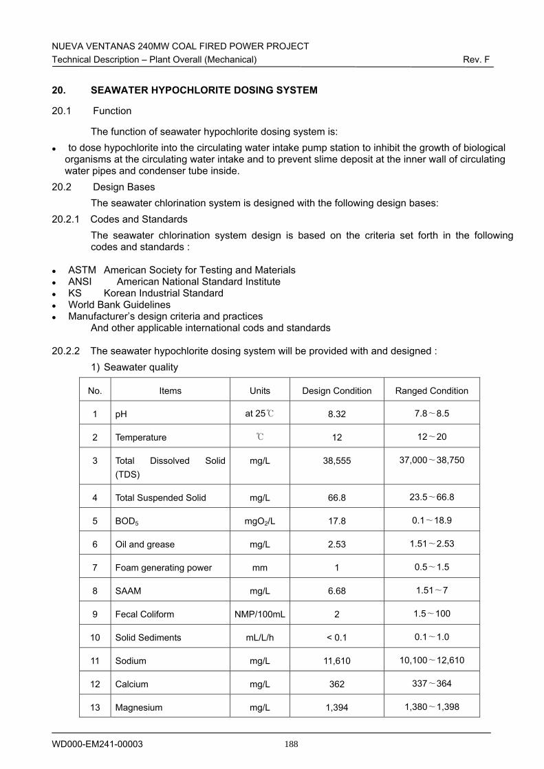
NUEVA VENTANAS 240MW COAL FIRED POWER PROJECT Technical Description – Plant Overall (Mechanical) Rev. F
WD000-EM241-00003 188
20. SEAWATER HYPOCHLORITE DOSING SYSTEM
20.1 Function
The function of seawater hypochlorite dosing system is: to dose hypochlorite into the circulating water intake pump station to inhibit the growth of biological
organisms at the circulating water intake and to prevent slime deposit at the inner wall of circulating water pipes and condenser tube inside.
20.2 Design Bases The seawater chlorination system is designed with the following design bases:
20.2.1 Codes and Standards The seawater chlorination system design is based on the criteria set forth in the following codes and standards :
ASTM American Society for Testing and Materials ANSI American National Standard Institute KS Korean Industrial Standard World Bank Guidelines Manufacturer’s design criteria and practices
And other applicable international cods and standards
20.2.2 The seawater hypochlorite dosing system will be provided with and designed : 1) Seawater quality
No. Items Units Design Condition Ranged Condition
1 pH at 25℃ 8.32 7.8∼8.5
2 Temperature ℃ 12 12∼20
3 Total Dissolved Solid (TDS)
mg/L 38,555 37,000∼38,750
4 Total Suspended Solid mg/L 66.8 23.5∼66.8
5 BOD5 mgO2/L 17.8 0.1∼18.9
6 Oil and grease mg/L 2.53 1.51∼2.53
7 Foam generating power mm 1 0.5∼1.5
8 SAAM mg/L 6.68 1.51∼7
9 Fecal Coliform NMP/100mL 2 1.5∼100
10 Solid Sediments mL/L/h < 0.1 0.1∼1.0
11 Sodium mg/L 11,610 10,100∼12,610
12 Calcium mg/L 362 337∼364
13 Magnesium mg/L 1,394 1,380∼1,398
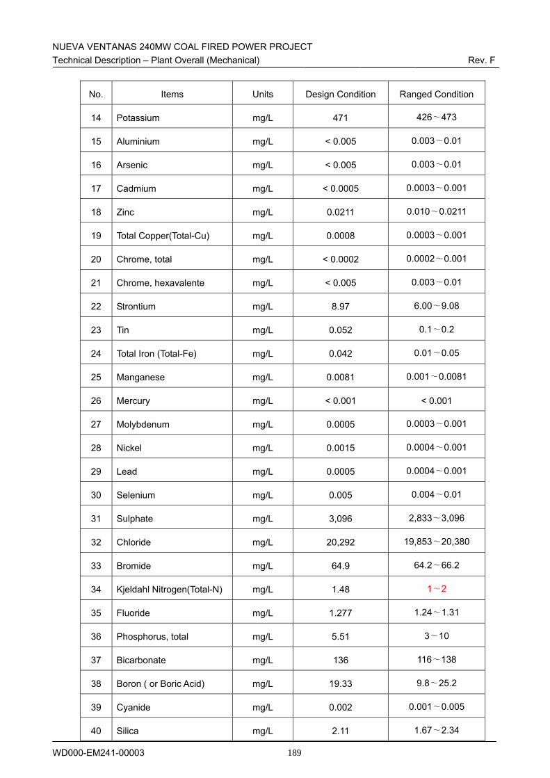
NUEVA VENTANAS 240MW COAL FIRED POWER PROJECT Technical Description – Plant Overall (Mechanical) Rev. F
WD000-EM241-00003 189
No. Items Units Design Condition Ranged Condition
14 Potassium mg/L 471 426∼473
15 Aluminium mg/L < 0.005 0.003∼0.01
16 Arsenic mg/L < 0.005 0.003∼0.01
17 Cadmium mg/L < 0.0005 0.0003∼0.001
18 Zinc mg/L 0.0211 0.010∼0.0211
19 Total Copper(Total-Cu) mg/L 0.0008 0.0003∼0.001
20 Chrome, total mg/L < 0.0002 0.0002∼0.001
21 Chrome, hexavalente mg/L < 0.005 0.003∼0.01
22 Strontium mg/L 8.97 6.00∼9.08
23 Tin mg/L 0.052 0.1∼0.2
24 Total Iron (Total-Fe) mg/L 0.042 0.01∼0.05
25 Manganese mg/L 0.0081 0.001∼0.0081
26 Mercury mg/L < 0.001 < 0.001
27 Molybdenum mg/L 0.0005 0.0003∼0.001
28 Nickel mg/L 0.0015 0.0004∼0.001
29 Lead mg/L 0.0005 0.0004∼0.001
30 Selenium mg/L 0.005 0.004∼0.01
31 Sulphate mg/L 3,096 2,833∼3,096
32 Chloride mg/L 20,292 19,853∼20,380
33 Bromide mg/L 64.9 64.2∼66.2
34 Kjeldahl Nitrogen(Total-N) mg/L 1.48 1∼2
35 Fluoride mg/L 1.277 1.24∼1.31
36 Phosphorus, total mg/L 5.51 3∼10
37 Bicarbonate mg/L 136 116∼138
38 Boron ( or Boric Acid) mg/L 19.33 9.8∼25.2
39 Cyanide mg/L 0.002 0.001∼0.005
40 Silica mg/L 2.11 1.67∼2.34
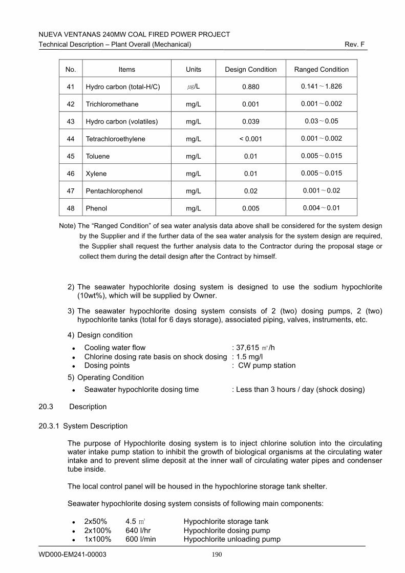
NUEVA VENTANAS 240MW COAL FIRED POWER PROJECT Technical Description – Plant Overall (Mechanical) Rev. F
WD000-EM241-00003 190
No. Items Units Design Condition Ranged Condition
41 Hydro carbon (total-H/C) ㎍/L 0.880 0.141∼1.826
42 Trichloromethane mg/L 0.001 0.001∼0.002
43 Hydro carbon (volatiles) mg/L 0.039 0.03∼0.05
44 Tetrachloroethylene mg/L < 0.001 0.001∼0.002
45 Toluene mg/L 0.01 0.005∼0.015
46 Xylene mg/L 0.01 0.005∼0.015
47 Pentachlorophenol mg/L 0.02 0.001∼0.02
48 Phenol mg/L 0.005 0.004∼0.01
Note) The “Ranged Condition” of sea water analysis data above shall be considered for the system design by the Supplier and if the further data of the sea water analysis for the system design are required, the Supplier shall request the further analysis data to the Contractor during the proposal stage or collect them during the detail design after the Contract by himself.
2) The seawater hypochlorite dosing system is designed to use the sodium hypochlorite (10wt%), which will be supplied by Owner.
3) The seawater hypochlorite dosing system consists of 2 (two) dosing pumps, 2 (two) hypochlorite tanks (total for 6 days storage), associated piping, valves, instruments, etc.
4) Design condition
Cooling water flow : 37,615 ㎥/h Chlorine dosing rate basis on shock dosing : 1.5 mg/l Dosing points : CW pump station
5) Operating Condition Seawater hypochlorite dosing time : Less than 3 hours / day (shock dosing)
20.3 Description
20.3.1 System Description
The purpose of Hypochlorite dosing system is to inject chlorine solution into the circulating
water intake pump station to inhibit the growth of biological organisms at the circulating water intake and to prevent slime deposit at the inner wall of circulating water pipes and condenser tube inside.
The local control panel will be housed in the hypochlorine storage tank shelter. Seawater hypochlorite dosing system consists of following main components:
2x50% 4.5 ㎥ Hypochlorite storage tank 2x100% 640 l/hr Hypochlorite dosing pump 1x100% 600 l/min Hypochlorite unloading pump
NUEVA VENTANAS 240MW COAL FIRED POWER PROJECT Technical Description – Plant Overall (Mechanical) Rev. F
WD000-EM241-00003 191
20.3.2 System Operation and Control
The NaOCl injection into seawater intake mouth & cooling water intake station are realised by each two(2) x 100% dosing pump. (2 Working)
The flow rate is adjustable manually on the pumps
The pumps are controlled locally by push buttons
The NaOCl solution is injected into the each intake station according to the analyser
results or upon chemist demand in order to keep the desired quality of water
In case of high pressure on the discharge side of pump, the internal pressure relief valve will open automatically and the oil return to pump head.
Pressure detection devices for High Pressure cut-out of chemical feed pump.
NUEVA VENTANAS 240MW COAL FIRED POWER PROJECT Technical Description – Plant Overall (Mechanical) Rev. F
WD000-EM241-00003 192
21. DESALINATED WATER SUPPLY SYSTEM (4.15.1.2, 4.17)
21.1 Function
The functions of the desalinated water supply system are: to produce desalinated water from sea water with salt content for demineralised water in sufficient
quality for use as boiler feed water to produce the desalinated water for process and wash water to produce the desalinated water for fire fighting water
21.2 Design Bases The desalinated water supply system is designed with the following design bases:
21.2.1 Codes and Standards The desalinated water supply system design is based on the criteria set forth in the following documents and standards:
ASME B31.1 Power Piping ASTM American Society for Testing and Materials ANSI American National Standard Institute KS Korea Industrial Standards JIS Japanese Industrial Standards Manufacturer’s design criteria and practices
And other applicable international codes and standards 21.2.2 The desalinated water supply system will be designed :
1) Product capacity and number of units : - Product capacity : 2,400 m3/day of desalinisation water - Number of units : 2 - Capacity of each unit : 1,200 m3/day - Type of unit : Mechanical Vapor Compression 2) Capacity bases of desalinated plant
Consumption Flow x Redundancy Capacity
Demineralized water: 400 m3/day x 2 = 800 m3/day
FGD : 1,000 m3/day x 1 = 1,000 m3/day
Ash water: 400 m3/day x 1 = 400 m3/day
Service water: 72 m3/day x 1= 72 m3/day
Potable water: 48 m3/day x 1 = 48 m3/day
TOTAL: 2,320 m3/day
3) Seawater quality The desalinated water supply system shall be designed having seawater analysis given in the Clause 20.2.2.
4) Desalinated water quality The desalinated water quality will be as follows :
Desalinated Water Analysis
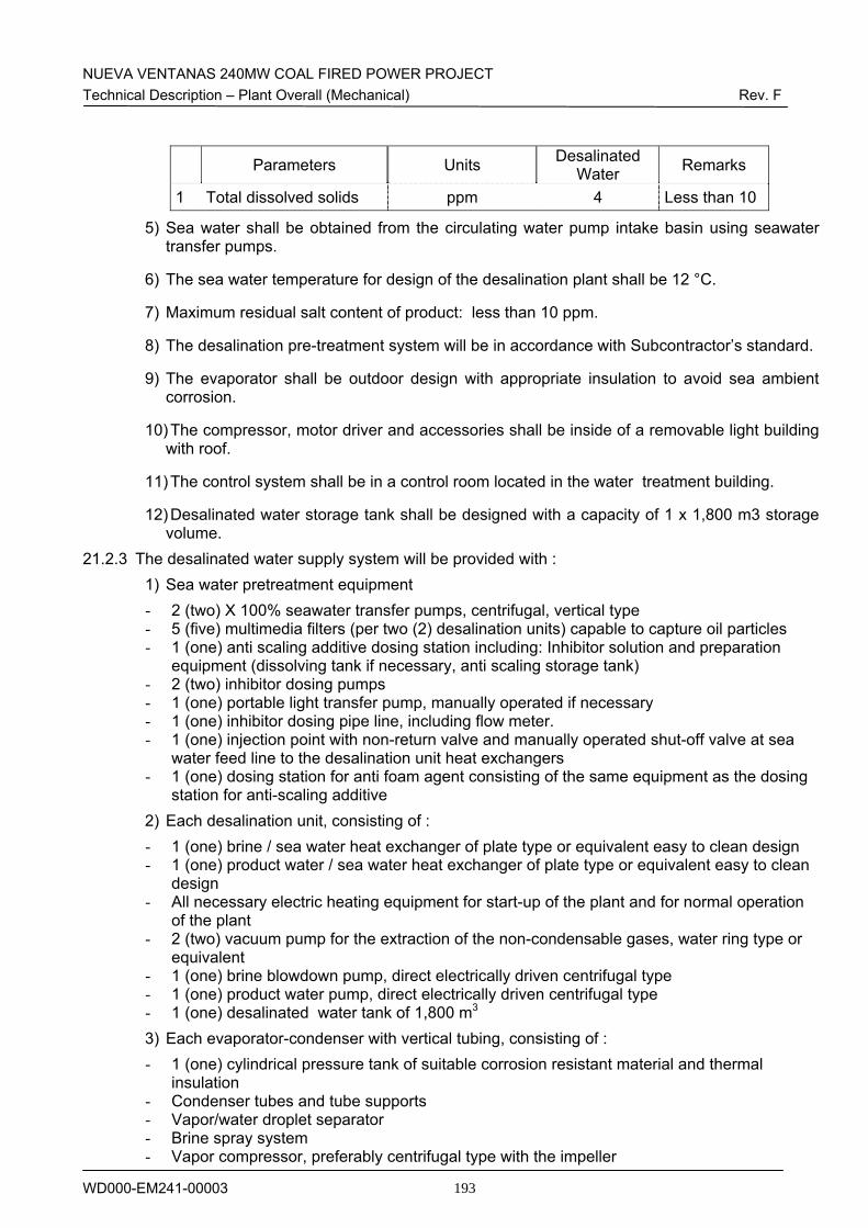
NUEVA VENTANAS 240MW COAL FIRED POWER PROJECT Technical Description – Plant Overall (Mechanical) Rev. F
WD000-EM241-00003 193
Parameters Units Desalinated Water Remarks
1 Total dissolved solids ppm 4 Less than 10
5) Sea water shall be obtained from the circulating water pump intake basin using seawater transfer pumps.
6) The sea water temperature for design of the desalination plant shall be 12 °C.
7) Maximum residual salt content of product: less than 10 ppm.
8) The desalination pre-treatment system will be in accordance with Subcontractor’s standard.
9) The evaporator shall be outdoor design with appropriate insulation to avoid sea ambient corrosion.
10) The compressor, motor driver and accessories shall be inside of a removable light building with roof.
11) The control system shall be in a control room located in the water treatment building.
12) Desalinated water storage tank shall be designed with a capacity of 1 x 1,800 m3 storage volume.
21.2.3 The desalinated water supply system will be provided with : 1) Sea water pretreatment equipment - 2 (two) X 100% seawater transfer pumps, centrifugal, vertical type - 5 (five) multimedia filters (per two (2) desalination units) capable to capture oil particles - 1 (one) anti scaling additive dosing station including: Inhibitor solution and preparation
equipment (dissolving tank if necessary, anti scaling storage tank) - 2 (two) inhibitor dosing pumps - 1 (one) portable light transfer pump, manually operated if necessary - 1 (one) inhibitor dosing pipe line, including flow meter. - 1 (one) injection point with non-return valve and manually operated shut-off valve at sea
water feed line to the desalination unit heat exchangers - 1 (one) dosing station for anti foam agent consisting of the same equipment as the dosing
station for anti-scaling additive 2) Each desalination unit, consisting of : - 1 (one) brine / sea water heat exchanger of plate type or equivalent easy to clean design - 1 (one) product water / sea water heat exchanger of plate type or equivalent easy to clean
design - All necessary electric heating equipment for start-up of the plant and for normal operation
of the plant - 2 (two) vacuum pump for the extraction of the non-condensable gases, water ring type or
equivalent - 1 (one) brine blowdown pump, direct electrically driven centrifugal type - 1 (one) product water pump, direct electrically driven centrifugal type - 1 (one) desalinated water tank of 1,800 m3 3) Each evaporator-condenser with vertical tubing, consisting of : - 1 (one) cylindrical pressure tank of suitable corrosion resistant material and thermal
insulation - Condenser tubes and tube supports - Vapor/water droplet separator - Brine spray system - Vapor compressor, preferably centrifugal type with the impeller
NUEVA VENTANAS 240MW COAL FIRED POWER PROJECT Technical Description – Plant Overall (Mechanical) Rev. F
WD000-EM241-00003 194
- Support frame for the evaporator-condenser - All the connecting pipe lines, valves and fittings of stainless steel, rubber lined or plastic
material suitable for the severe corrosive operating conditions. 21.3 Description
21.3.1 General Description The seawater desalination plant will produce the distillate water of appropriate quality and
quantity necessary for feeding water to demineralisation plant, service water and fire fighting system.
All seawater desalination system compounds are arranged near Water Treatment Plant
Building. The control and switch panel is installed in a separate room of the CWP Elec. & Control Building.
The seawater desalination plant will be of mechanical vapour compression(MVC) type and
2(Two) complete sets of seawater desalination plant shall be supplied. Each of seawater desalination plant consist of following main components:
1x100% 1,200 m3/day MVC Unit 1x100% Brine discharge pump 1x100% Product water pump 1x100% Product water booster pump 2x100% Circulation pump 1x100% Product heat exchanger 1x100% Brine heat exchanger 1x100% Vacuum system for extraction of the non-condesnsable
Gases. 1x100% Electrical boiler heating system 1x100% Antiscalant dosing system 1x100% Antifoam dosing system
The seawater will be pumped from the circulating water intake pump station to the pretratment
system composed of 5(five) multi-media filter by 2 x 100% seawater transfer pumps to meet the demand of desalination plant and then pumped to the desalination plant by 2(two) MVC feed pumps. As a portion of the main cooling water stream, this seawater will be filtered and chlorinated in the seawater intake. To prevent scaling inside the evaporators, an antiscalant will be dosed to the seawater stream, before entering the evaporators.
The distillate water will be pumped to the desalinated water storage tank. The non condensable gases removal system consists of an auxiliary condenser and two
vacuum pumps. The vacuum pumps are of a rotary displacement type, with liquid ring sealing. Each of the vacuum pumps is with electric motor operating. During operation one is used and the second one is on standby, but to accelerate the start-up, both pumps can be used in parallel for the initial air.
The brine blowdown from the system will be extracted by one 100% brine pump and will be discharged through the circulating water seal pit.
The plant will be equipped with chemical injection equipment for dosing antiscalant and
antifoam agents and the vacuum system to extract non-condensable gases released from seawater in the evaporator.
The plant will also include chemical cleaning equipment for periodic removal of scale deposits
from the surface.
NUEVA VENTANAS 240MW COAL FIRED POWER PROJECT Technical Description – Plant Overall (Mechanical) Rev. F
WD000-EM241-00003 195
The distillate water from the seawater desalination will be collected and pumped by 1 x 100%
product water pump and 1 x 100% product water booster pump to one desalinated water storage tanks of 1,800 m3 capacity, made of carbon steel/epoxy coated, equipped with necessary relevant items.
Fire fighting water will be taken from the desalinated water storage tank.
Two electric steam boilers are supplied for heating the evaporator during the start-up and the circulated brine during steady operation. One product pH control system is supplied for serving the total product water flow. The system consists of the following items:
A pH measure and control system, consisting of pH meter and transmitter, to control through the computer the dosing pump.
Caustic Soda solution tank Two dosing pumps, one is operating while the second one is on stand-by.
21.3.2 System operation and Control The operation of the seawater desalination system will be integrated and operated in PLC
system. Also, several signals from local PLC are transmitted to the DCS for remote monitoring of operation data.
The main equipment of desalination system is consisted of two (A and B) trains. The seawater
desalination system will be operated either manually or automatically. In manual mode, system will be started/stopped manually. In case of automatic mode, system will be controlled automatically by level switch of desalninated water storage tank. The chemical feed rate control will be manually pre-set according to flow rate. The seawater desalination system cleaning will be done only manually.
The Monitoring Signal exchange with the DCS will comprise:
• Analogue: - Amount of product water stored in the storage tanks - Actual conductivity of the product water at the outlet of each evaporator unit
• Binary:
- Electrical fault - Mechanical fault - Status message from evaporator unit in operation
A command ON/OFF for the seawater desalination system from the central control room in the
Central Control Building is not envisaged.
NUEVA VENTANAS 240MW COAL FIRED POWER PROJECT Technical Description – Plant Overall (Mechanical) Rev. F
WD000-EM241-00003 196
22. DEMINERALIZED WATER SUPPLY SYSTEM (4.15.1.3, 4.17.3)
22.1 Function
The functions of demineralised water supply system are : to provide and make up demineralised water to boiler to make up demineralised water to closed cooling water system for the plant
22.2 Design Bases The demineralised water supply system is designed with the following design bases:
22.2.1 Codes and Standards The demineralised water supply system is designed based on the criteria set forth in the following codes and standards:
ASME B31.1 Power Piping ASTM American Society for Testing and Materials ANSI American National Standard Institute API American Petroleum Institute KS Korea Industrial Standards JIS Japanese Industrial Standards Manufacturer’s design criteria and practices
And other applicable international cods and standards
22.2.2 The demineralized water supply system will be designed : 1) Operation Condition - Demineralisation system 24 hours/day Continuous - Service water system 16 hours/day Intermittent - Potable water system 8 hours/day Intermittent 2) The demineralization plant consists of : two trains of 400 m3/day capacity each (total 800
m3/day) of demineralized water
3) The demineralisation plant shall be of electrodeionization (EDI).
4) For avoiding contamination problems in the demineralized water tank a bypass pipeline from demineralized water plant to cold condensate tank will be provided.
5) Unless other instructions from boiler manufacturer, demineralized water production must have at least the following characteristics:
- Conductivity less than : 0.1µS/cm at 25℃ - Silica acid less than : 0.02 ppm
22.2.3 The demineralized water supply system will be provided with:
1) 2 (two) EDI demineralization trains of 400m3/day each, including : - 2 (two) x 100% EDI feed pump for each train - 1 (one) EDI stack for each train - 2 (two) x 100% concentration recycle pumps for each train - 1 (one) rectifier for each train - 1 (one) chemical cleaning system common for both trains - Cleaning system for membranes of EDI system 2) 1 (one) 1,800 m3 demineralized water storage tank with by-pass pipeline
22.3 Description
NUEVA VENTANAS 240MW COAL FIRED POWER PROJECT Technical Description – Plant Overall (Mechanical) Rev. F
WD000-EM241-00003 197
22.3.1 General Description The water treatment plant is located inside the water treatment building. The purpose of the water treatment plant is to supply Demineralized water for power plant. 2(Two) complete sets of demineralization system shall be supplied. Each of demineralization
system consists of following main components:
2x100% 18.75 m3/hr EDI feed pump 1(One) set 18.75 m3/hr EDI stack 1(One) set Rectifier for EDI 1x100% 0.9 m3 EDI cleaning tank for both train 2x100% 16.7 m3/hr EDI cleaning pumps 1x100% 16.7 m3/hr EDI cleaning micro filter 1 Unit 1800 m3 Demineralized water storage tank 1x100% Eye washer & safety shower
Distillate water is transferred from the seawater desalination plant to the new desalinated water
tank. Distillate water is transferred from the desalinated water storage tank to the demineralised
water plant to be demineralised. The demineralised water is pumped to the demineralised water storage tank with a capacity of
1 x 1,800 m3. From there the make up water is transferred to the water/steam cycle to recover the steam losses. The relatively small make up water demand of the closed cooling systems is recovered from the same tank.
The conductivity of distillate water to be treated in the demineralised water plant is lower than 10 μS/cm.
The demineralised water plant comprises two (2) identical EDI trains. EDI is the process of removing ionized or ionisable substances from water using ion exchange membranes, electrically active media (typically ion exchange resin), and a DC electric potential. Continuous demineralization in the ionpure module consists of three coupled processes like feed, removal and regeneration.
22.3.2 System Operation and Control The plant will have a local control panel located in a separate room of the water treatment
building. Indicating instruments, monitors and control facilities will be arranged on this panel.
The start-up/shutdown of the plant is controlled automatically by the level of the demineralised water storage tanks.
The demineralised water which is treated by EDI unit is transferred to demineralised water tank. The recovery ratio of the EDI will be not less than 90% and it’s 10% of concentration water will be transferred to reclaim water pond. The two EDI units will be capable of operating individual or simultaneously in accordance with level of demineralised water storage tank and run service fully automatically in response to operation button by the operator.
When EDI service re-start after stopping due to high level signal of demineralised water storage tank, rinse blow down water of EDI will be returned to desalinated water storage tank during time to be reached to guaranteed conductivity.
During service, if the continuously measured, indicated and recorded conductivity after the EDI exceeds the first limiting value, e.g. about 0.1 µS/cm, a warning will be given : e.q. 5 ti 30 minutes later or if the conductivity exceeds the second limiting value of about 0.2 µS/cm on
NUEVA VENTANAS 240MW COAL FIRED POWER PROJECT Technical Description – Plant Overall (Mechanical) Rev. F
WD000-EM241-00003 198
alarm will be given and the EDI must shut down automatically. The Monitoring Signal exchange with the DCS shall comprise as a minimum:
Analogue : - Amount of demineralized water - Level of demineralized water in supply tanks - Conductivity of demineralized water
Binary: - Electrical fault - Mechanical fault - Status message from demineralization train in operation
A command ON/OFF for the water demineralization from the central control room in the Central Control Building is not envisaged.
NUEVA VENTANAS 240MW COAL FIRED POWER PROJECT Technical Description – Plant Overall (Mechanical) Rev. F
WD000-EM241-00003 199
23. POTABLE WATER SYSTEM (4.15.1.4, 4.15.1.6, 4.15.2.2)
23.1 Function
The functions of potable water system are : to supply the potable water requirements for the power station operating personnel to store and distribute the potable water supplied from existing Ventanas Power Station with a
supply limitation of 5 m3/d 23.2 Design Bases
The potable water system is designed with the following design bases :
23.2.1 Codes and Standards The potable water system design is based on the criteria set forth in the following documents and standards:
ASME B31.1 Power Piping ASTM American Society for Testing and Materials ANSI American National Standard Institute
National Plumbing Code KS Korea Industrial Standards Manufacturer’s design criteria and practices
And other applicable international cods and standards
23.2.2 The potable water supply system will be provided with and designed : 1) 1 (one) potable water tank of 100 m3
2) 2 (two) x 100% pumps
3) Pipelines of corrosion-proof materials
4) Plastic pipework made of HDPE for secondary pipes only, i.e. drains and vents
5) 1 (one) connection line to the existing potable / sanitary water distribution system
23.3 Description
23.3.1 General Description 1(One) complete set of potable water system shall be supplied. Potable water system consists
of following main components: 2x100% 10 m3/hr Potable water transfer pump 1(One) set 6 m3/hr Activated carbon filter 1x100% 0.2 m3 Hypochlorite dosing tank 1x100% 1.8 m3 CaCl2 dosing tank 1x100% 0.6 m3 NaHCO3 dosing tank 2x100% 1.9 l/hr Hypochlorite dosing pump 2x100% 15.3 l/hr CaCl2 dosing pump 2x100% 3.7 l/hr NaHCO3dosing pump
The desalinated water which is treated by MVC and stored in desalinated water tank is fed to 100% x 1 set of activated carbon filter by potable water transfer pumps.
The activated carbon has a honeycomb like structure that has enormous total surface area and
a large capacity for absorbing impurities in water. Therfore activated carbon filter is used to remove organics such as phenols and many pesticides efficiency.
Also, substances causing moldy, musty or woody tastes and orders are also removed by this
NUEVA VENTANAS 240MW COAL FIRED POWER PROJECT Technical Description – Plant Overall (Mechanical) Rev. F
WD000-EM241-00003 200
activated carbon filter.
The filter should be backwashed to keep the bed clean. The filter backwashing is recommended to be done one time per one day.
The desalinated water which is treated by MVC is not proper for human to use as potable water due to little minerals. So, the desalinated water should be remineralized and chlorinated by chemical dosing system for potable in order to be able to be used as potable water.
The chemical dosing system for potable consist of hypochlorite dosing system, CaCl2 dosing system and NaHCO3 dosing system.
23.3.2 System Operation and Control All valves used in connection with the backwashing and potable water transfer pumps shall be controlled automatically or semi-automatically by the PLC and also operations such as service and stand-by shall be controlled on the HMI.
Each chemical solution such as Hypochlorite, CaCl2, NaHCO3, for potable is poured to the each dosing tank and is diluted by supplying service water into tank and agitation. And each chemical will be injected in the discharge line of activated carbon filter.
The Monitoring Signal exchange with the DCS shall comprise as a minimum:
Analogue : - Amount of potable water - pH, Conductivity of potable water
Binary: - Electrical fault - Mechanical fault - Status message from potable water system in operation
A command ON/OFF for the potable water system from the central control room in the Central Control Building is not envisaged.
NUEVA VENTANAS 240MW COAL FIRED POWER PROJECT Technical Description – Plant Overall (Mechanical) Rev. F
WD000-EM241-00003 201
24. WASTEWATER TREATMENT SYSTEM (4.17.4)
24.1 Function
The functions of wastewater treatment system are : to treat all plant effluents, to meet the discharge limits before disposal to seal pit or outfall of CW
discharge, such as : i) water treatment plant effluent, ii) boiler blowdown, iii) floor drains, iv) treated sewerage, v) waste water generated in cleaning of air preheaters, vi) chemical spillage, vii) oily drains from fuel oil tank, transformer area and turbine hall, viii) etc.
to selectively recycle the treated wastewater for further treatment in the water treatment plant for reuse, with a view to optimise the overall water consumption of the plant.
24.2 Design Bases The wastewater treatment system is designed with the following design bases :
24.2.1 Codes and Standards The wastewater treatment system design is based on the criteria set forth in the following documents and standards:
ASME B31.1 Power Piping ASTM American Society for Testing and Materials ANSI American National Standard Institute API American Petroleum Institute KS Korea Industrial Standards Manufacturer’s design criteria and practices
And other applicable international cods and standards 24.2.2 The wastewater treatment system will be provided with and designed :
1) Wastewater sources Characteristic Description Source Abnormal wastewater
Boiler chemical cleaning wastewater Air heater cleaning wastewater Desalination chemical cleaning wastewater
Boiler Desalination system
Boiler blowdown water, Concentration water from water treatment System (EDI)
Spilled chemical Chemical tank area Chlorination chemical cleaning water Chlorination system
Chemical wastewater
Sampling wastewater Sampling equipment Equipment drainage Power house drainage Lubrication cooling facilities Steam turbine,
various rotating machine
Oily wastewater
Transformer and fuel storage tank area
Rainy drainage
2) Operation condition - Abnormal wastewater : 24 h/day - Chemical wastewater : 16 h/day - Oily wastewater : 8 h/day 3) Wastewater quantity and quality
No. Originates Q’ty Quality Remarks
NUEVA VENTANAS 240MW COAL FIRED POWER PROJECT Technical Description – Plant Overall (Mechanical) Rev. F
WD000-EM241-00003 202
pH SS COD Oil
1 Normal(Chemical) wastewater 550 2~13 50 80 -
2 Abnormal wastewater 800 2~13 500 1000 -
3 Oily wastewater 48 6~8 100 50 300
4) Effluent water quality (final disposal pump discharge) The effluent water quality conditions are as follows :
- pH 6~9 - TSS 50 ppm - Oil and grease < 10 ppm - Total residual chlorine < 0.2 ppm - Chromium, total < 2.5 ppm - Copper < 1.0 ppm - Iron < 10 ppm - Zinc < 5 ppm
- Temperature < 30 ℃
24.2.3 The wastewater treatment system will be provided with and designed :
1) A waste water treatment plant shall be provided to deal with the effluents. All effluents (e.g. water treatment plant effluent, boiler blowdown, waste water generated in cleaning of air preheaters and chemical spillage, oily drains from fuel oil tank, transformer area, floors and turbine hall, etc) shall be treated in the plant.
2) Contractor shall selectively recycle the treated wastewater for further treatment in the water treatment plant for reuse, with a view to optimise the overall water consumption of the plant.
3) The oily waste water treatment plant shall consist of : - an oily waste water collection pond and - Oil separators of CPI type and CPI type along with necessary pumps and piping for
transferring the oil separated waste water to the chemical waste water pond (normal wastewater pond) for further treatment.
4) Waste from water treatment plant, chemical spillages, chemical drains, etc, shall be collected in a chemical wastewater treatment pond (normal wastewater pond).
5) Irregular wastewater such as sourced from boiler chemical cleaning and air preheater cleaning will be collected in an abnormal waste water pond. An overflow line shall be provided to connect the chemical waste water pond to the abnormal waste water pond.
6) The abnormal waste water pond shall have the capacity to hold the maximum waste water generated during boiler chemical cleaning, or air preheater cleaning, or abnormal blowdown during any boiler upset conditions. Its size shall be estimated on the basis of largest volume of wastewater that may be generated by any of the above activities.
7) 2 (two) x 100% abnormal waste water pumps shall be provided to transfer the waste water from the abnormal waste water pond to the chemical waste water pond. Waste water in the abnormal wastewater pond will be gradually transferred to chemical waste water pond for pH adjustment in a neutralization basin, coagulation and settlement of sludge in a clarifier.
8) 2 (two) x 100% blowers and distribution pipes shall be provided for aeration of the waste water ponds, chemical waste water pond and abnormal waste water pond for flow equalization and supplying oxygen requirement of waste water.
9) 2 (two) x 100% chemical waste water pumps shall be provided to transfer the waste water from the chemical waste water pond to a pH adjustment tank where alkali or acid will be
NUEVA VENTANAS 240MW COAL FIRED POWER PROJECT Technical Description – Plant Overall (Mechanical) Rev. F
WD000-EM241-00003 203
added to adjust pH of the wastewater, and adding coagulant and coagulant aid in a coagulation tank before the waste water is sent to the clarifier (settling tank) for settlement of sludge. The sludge from the bottom of the settling basin shall be thickened and compacted before disposal to the authorized permit area.
10) The plant will be provided with necessary sumps with sump pumps and piping, level switches, local panels for transformers areas, boiler areas, condenser pit area, and diesel oil storage tank area. Waste water from these areas will be transferred to the chemical waste water pond or oily waste water pond depending on the characteristic of the waste water.
11) Runoff from coal storage and handling area adjacent to NVTS, which may be contaminated by coal, shall be directed to and settled in a settling pond.
12) Boiler blowdown water and EDI brine water will be collected into reclaim water pond for reuse.
13) Desalination brine and multimedia filter backwashing water will be discharged into the outfall directly without any treatment.
24.3 Description
24.3.1 General Description
24.3.1.1 Wastewater Treatment System The wastewater treatment system is to treat the plant’s wastewater generated from water treatment system, oil pumps area, transformer area, turbine generator area etc. These wastewater will be collected in a neutralisation pond, neutralised and discharged into seal chamber. The mentioned all wastes will be sent to the cooling water seal chamber and then discharged to the seal pit and the sea. The blowdown water arising from Boiler blow down and condensate drains is collected in the reclaim water pond for use of bottom ash handling system. After recirculation and uniform the temperature of blowdown water, it will be transfered to the bottom ash handling system. Wastewater Treatment System consists of following main components:
Abnormal wastewater treatment system Chemical wastewater treatment system Oily wastewater treatment system
All wastewater treatment system compounds are arranged near Water Treatment Plant Building. A local control panel will be furnished for the wastewater treatment system, and will display the controls, relays, other instruments and associated wiring. The control panel will be located indoor in control room. One pH-measurement, complete with recorder and high/low value alarms for neutralization pond will be included. Level indication of neutralization pond will also be included.
24.3.1.2 Abnormal Wastewater Treatment System Abnormal wastewater treatment system consists of following main components:
NUEVA VENTANAS 240MW COAL FIRED POWER PROJECT Technical Description – Plant Overall (Mechanical) Rev. F
WD000-EM241-00003 204
1x100% 900㎥ Abnormal wastewater pond 2x100% 6.7 ㎥/hr Abnormal wastewater pump
The irregular wastewater such as boiler chemical cleaning, air-heater washing water, etc., is collected in the abnormal wastewater pond whose capacity is 900 ㎥. These abnormal wastewater is homogenized by 0.03 m3/m2/min of blower air and then is transferred to the normal wastewater pond for 5 days. 2 sets of abnormal wastewater pump transfer wastewater to the normal wastewater pond.
24.3.1.3 Chemical Wastewater Treatment System Chemical wastewater treatment system consists of following main components:
1x100% 700㎥ Normal wastewater pond 2x100% 50 ㎥/hr Normal wastewater pump 1x100% 7.3㎥ pH adjust tank 1x100% 15 ㎥ Coagulation tank 1x100% 15 ㎥ Flocculation tank 1x100% 44 ㎥/hr Clarifier 1x100% 44 ㎥ Clarified water pond 2x100% 50 ㎥/hr Filter supply pump 1x100% 44 ㎥/hr Activated carbon filter 1x100% 22 ㎥ Final pH adjust pond 1x100% 132㎥ Effluent pond 2x100% 98 ㎥/hr Effluent & Backwashing pump 1x100% 5 ㎥/hr Thickener 1x100% 2 ㎥/hr Dehydrator with Recycle system 1 Unit Chemical dosing tank(Polymer, Coagulant, Acid, Caustic,
C-Polymer) 1 Unit Chemical dosing aid tank(Polymer, Coagulant) 1 Unit Chemical dosing pump
All effluent from the demineralized water plant has a various pH-value. Therefore the effluent pass a neutralization pond before being discharged to cooling water seal chamber. The material of the neutralization pond is coated by epoxy to protect acid attack. The installation of the pond is located besides the water treatment building below zero level. The neutralization pond will be fitted with a complete mixing system with water jets fed through the pressurised circulating water line of the neutralization water transfer pumps.
24.3.1.4 Oily Wastewater Treatment System
Oily wastewater treatment system consists of following main components:
1x100% 8 ㎥/hr API oil separator 1x100% 115 ㎥ Oil separated water pond 2x100% 8 ㎥/hr Oily water transfer pump 1x100% 8 ㎥/hr CPI oil separator 1x100% 5 ㎥ Skimmed oil pond
NUEVA VENTANAS 240MW COAL FIRED POWER PROJECT Technical Description – Plant Overall (Mechanical) Rev. F
WD000-EM241-00003 205
The oily wastewater generated from the plant area is transferred to API oil separator by pumping. This API oil separator removes contaminated free oil in the oily wastewater.
The treated oily wastewater is transferred to the oily wastewater pond by gravity and separated oil from API oil separator is transferred the skimmed oil pond for further treatment outside by other.
Gravity separation using API separators involves the removal of materials less dense than water.(such as free oils and air-entrained particulates).
The oil concentration is significant as higher oil concentrations are removed with greater efficiency than low oil concentrations since the lower limit of oil in the separator effluent is usually around 50 mg/l.
Removal of other contaminants in a separator is highly variable. COD removal efficiencies vary from 15 to 80 percent.
API oil separator is based on the removal of all free oil globules larger than 150 µm.
24.3.2 System Operation and Control The Wastewater Treatment Plant will be integrated and operated through local control panel and several signals are transmitted to the DCS for remote monitoring of operation data.
The wastewater system is automatically operated excluding flow adjustment of chemical dosing pumps and abnormal operation of wastewater pumps.
24.3.2.1 Abnormal Wastewater System The abnormal wastewater pump will be started/stopped automatically in accordance with level switch of Abnormal wastewater pond, then transferred to the normal wastewater pond for 5 days.
24.3.2.2 Chemical Wastewater System One level transmitter mounted in the neutralisation pond will be used for automatic control. The normal wastewater transfer pump will start up when reaching the high level point and will stop when the normal wastewater pond level has reached the low level point.
The pH-value in the pressure line of the normal wastewater transfer pumps will be continuously measured and recorded on local control panel.
In the case that pH of effluent exceed the effluent discharge limit, an isolation valve on the recirculation line to normal wastewater pond is opened while isolation valve on the discharge line to cooling water outfall is closed simultaneously. This sequence ensures that untreated or poorly treated wastewater will not be discharged to outside.
24.3.2.3 Oily Wastewater Treatment System
The oily water transfer pump will be started/stopped automatically in accordance with level switch of Oily wastewater pond, then treated water from oily wastewater pond and CPI oil separator will be transferred to normal wastewater pond by gravity.
NUEVA VENTANAS 240MW COAL FIRED POWER PROJECT Technical Description – Plant Overall (Mechanical) Rev. F
WD000-EM241-00003 206
25. WATER RECLAIMING SYSTEM (4.15.1.5, 4.15.2.1, 4.15.2.4)
25.1 Function
The function of water reclaiming system is: to recycle water for bottom ash handling system
25.2 Design Bases The water reclaiming system is designed with the following design bases :
25.2.1 Codes and Standards The water reclaiming system design is based on the criteria set forth in the following documents and standards:
ASME ASME B31.1 Power Piping ASTM American Society for Testing and Materials ANSI American National Standard Institute KS Korea Industrial Standards Manufacturer’s design criteria and practices
And other applicable international cods and standards 25.2.2 The water reclaiming system will be provided with and designed :
1) 1 (one) reclaim water pond made of concrete with appropriate lining or coating
2) 2 (two) reclaim water pumps to bottom ash handling system
3) The pumps of the reject water system are to be stainless steel 304 or equivalent.
4) Reject water such as boiler blowdown water, EDI concentrate water and effluent water shall be collected in the reclaim water pond and then reclaiming water shall be used for the bottom ash handling system.
5) Overflow water from reclaim water pond shall flow into the normal wastewater pond.
6) If reclaiming water quantity is insufficient for the bottom ash handling system, the desalinated water shall be used for bottom ash handling system.
7) The reclaim water system is to be designed for normal operation and to contribute to the water consumption for bottom ash handling system.
8) The reclaim water pond is to be designed as a reinforced concrete construction near the wastewater pond area.
25.3 Description
25.3.1 General Description 1(One) complete set of Reclaim water system shall be supplied. Reclaim water system
consists of following main components: 1x100% 115 m3 Reclaim water pond 2x100% 35 m3/hr Reclaim water pump
Reclaim water is equalized and homogenized by 0.03 m3/m2/min of blower air in this pond that has 6 hrs retention time and 115 m3 capacity and then is supplied to the bottom ash handling system by reclaim water pumps.
25.3.2 System Operation and Control All valves used in connection with the reclaim water pumps shall be controlled automatically by the PLC and also operations such as service and stand-by shall be controlled on the HMI.
NUEVA VENTANAS 240MW COAL FIRED POWER PROJECT Technical Description – Plant Overall (Mechanical) Rev. F
WD000-EM241-00003 207
One level transmitter mounted in the reclaim water pond will be used for automatic control. The reclaim water pump will start up when reaching the high level point and will stop when the reclaim water pond level has reached the low level point.
The Monitoring Signal exchange with the DCS shall comprise as a minimum:
Analogue : - Amount of reclaim water
Binary: - Electrical fault - Mechanical fault - Status message from potable water system in operation
A command ON/OFF for the potable water system from the central control room in the Central Control Building is not envisaged.
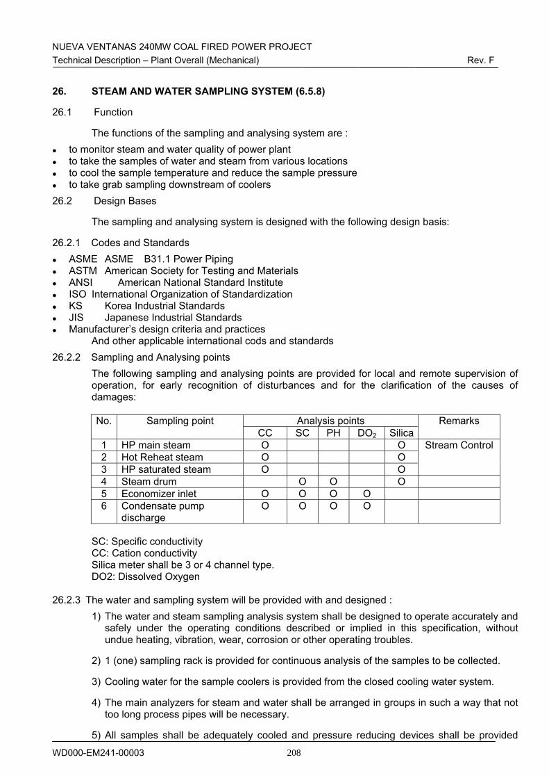
NUEVA VENTANAS 240MW COAL FIRED POWER PROJECT Technical Description – Plant Overall (Mechanical) Rev. F
WD000-EM241-00003 208
26. STEAM AND WATER SAMPLING SYSTEM (6.5.8)
26.1 Function
The functions of the sampling and analysing system are : to monitor steam and water quality of power plant to take the samples of water and steam from various locations to cool the sample temperature and reduce the sample pressure to take grab sampling downstream of coolers
26.2 Design Bases
The sampling and analysing system is designed with the following design basis:
26.2.1 Codes and Standards ASME ASME B31.1 Power Piping ASTM American Society for Testing and Materials ANSI American National Standard Institute ISO International Organization of Standardization KS Korea Industrial Standards JIS Japanese Industrial Standards Manufacturer’s design criteria and practices
And other applicable international cods and standards 26.2.2 Sampling and Analysing points
The following sampling and analysing points are provided for local and remote supervision of operation, for early recognition of disturbances and for the clarification of the causes of damages:
Analysis points No. Sampling point CC SC PH DO2 Silica
Remarks
1 HP main steam O O 2 Hot Reheat steam O O 3 HP saturated steam O O
Stream Control
4 Steam drum O O O 5 Economizer inlet O O O O 6 Condensate pump
discharge O O O O
SC: Specific conductivity CC: Cation conductivity Silica meter shall be 3 or 4 channel type. DO2: Dissolved Oxygen
26.2.3 The water and sampling system will be provided with and designed : 1) The water and steam sampling analysis system shall be designed to operate accurately and
safely under the operating conditions described or implied in this specification, without undue heating, vibration, wear, corrosion or other operating troubles.
2) 1 (one) sampling rack is provided for continuous analysis of the samples to be collected.
3) Cooling water for the sample coolers is provided from the closed cooling water system.
4) The main analyzers for steam and water shall be arranged in groups in such a way that not too long process pipes will be necessary.
5) All samples shall be adequately cooled and pressure reducing devices shall be provided
NUEVA VENTANAS 240MW COAL FIRED POWER PROJECT Technical Description – Plant Overall (Mechanical) Rev. F
WD000-EM241-00003 209
where necessary.
6) Manual sampling shall be possible at each analyzer. Only in the case of very low pressure and temperatures, transmitters for measurements such as conductivity, pH-value, etc. be installed directly in the pipe.
7) A protective device shall be incorporated in the sample cooler to isolate the analyzer in the event of excessive temperature due to lack of cooling and preventing cells damages. In order to eliminate the influence of ammonia and hydrazine to the conductivity measurement cation filters shall be provided. The cation filters shall have visible color indicators to show when they have to be regenerated.
8) For all analyzers temperature compensation shall be provided, the temperature sensor shall be an integral part of the probe.
9) The sampling and analyzing system shall have a volt-free contact for a remote alarm in plant DCS.
26.3 Description
26.3.1 General Description One (1) sampling rack is located on the sampling room in the ST building. Samples from the system are led to the sampling rack. The tapping point and the measurements are shown in the piping and instrument diagrams. (WD162-EJ103-00001 and –00002) A typical arrangement of equipment for a sample conditioning is a sample cooler with a local temperature indicator of the sample downstream. Pneumatic-actuated shut-off valve is provided in the sampling pipes. A throttle valve is located downstream of the sampling coolers and the shut-off valve in order to avoid steaming of the sample. After the throttle valve parallel sampling lines are installed for automatic and manual analyses or for blowdown drain. The sample coolers are arranged for external counterflow and the possibility to take manual samples is also provided for sample coolers. All sample coolers are provided with stainless steel trays. The drain of these trays is connected to the waste drain system. All sampling pipework valves and reducing valves are fabricated from stainless steel.
26.3.2 System Operation and Control
Pneumatic-actuated shut-off valve is provided in the sampling pipes, which is closed automatically in case of failure of the cooling water (excessive temperature of the sample). The conductivity cells are compensated for a relevant temperature of the analyser require to generate ideal measuring output.
NUEVA VENTANAS 240MW COAL FIRED POWER PROJECT Technical Description – Plant Overall (Mechanical) Rev. F
WD000-EM241-00003 210
27. FIRE DETECTION AND PROTECTION SYSTEM (4.13)
27.1 Function
The functions of fire protection system are : to provide early warning and suppression of fire to provide the property protection from fire hazard to provide the life safety from fire hazard
27.2 Design Bases
The fire detection and protection system is designed with the following design bases :
27.2.1 Codes and Standards
The fire detection and protection system design is based on the criteria set forth in the following documents and standards:
FM Factory Mutual Loss Prevention Guidelines NFPA National Fire Protection Association Chilean Fire Regulations Manufacturer’s design criteria and practices
And other applicable international cods and standards Equivalent international codes may be used, subject to Owner prior acceptance. In addition to these codes and standards, Contractor shall comply with federal and local laws, codes and regulations.
27.2.2 The fire detection and protection system will be provided with and designed : Preaction System Wet Pipe Automatic Sprinkler System Deluge Systems Area Fire Detection Systems Fire Control Cabinet Fire Control Logic Cabinets Local Control Cabinets Input and Final Output Devices (such as thermal detectors ionization detectors, photoelectric
detectors, solenoid valves, horns, indicating lights, etc.) Digital Logic Elements Standpipes and Hose Connections with Accessories Electric Motor Driven Fire Pump Electric Motor Driven Pressure Maintenance Pump Diesel Driven Fire Pump Portable Fire Extinguishers
26.3 Description
26.3.1 General Description
Refer to the technical description for fire fighting system which was prepared separately.
NUEVA VENTANAS 240MW COAL FIRED POWER PROJECT Technical Description – Plant Overall (Mechanical) Rev. F
WD000-EM241-00003 211
28. NITROGEN STORAGE AND SUPPLY SYSTEM (4.26)
28.1 Function
The function of nitrogen storage and supply system is : to provide equipment blanketing for corrosion protection
28.2 Design Bases The nitrogen storage and supply system is designed with the following design bases :
28.2.1 Codes and Standards The nitrogen storage and supply system design is based on the criteria set forth in the following documents and standards:
ASME B31.1 Power Piping Manufacturer’s design criteria and practices
And other applicable international cods and standards 28.2.2 The nitrogen storage and supply system will be provided with and designed :
1) The nitrogen storage and supply system is designed to use for equipment blanketing for corrosion protection.
2) Nitrogen shall be furnished in cylinders. Contractor shall furnish piping to the following equipment :
- Gland steam condenser
- LP heaters (tube side)
- LP heaters (shell side except LP heater I)
- HP heaters (tube and shell sides)
- Steam generating units
3) Contractor shall calculate the quantity of nitrogen required to blanket all the equipment specified.
4) The equipment shall be designed so that nitrogen supply cylinders can be replaced without system interruption.
28.3 Description
28.3.1 General Description Two (2) N2 cylinder racks are located on the ground level of coal tripper tower. Each rack consists of manifold with ten (10) cylinders, and connected to one (1) common supply line with pressure reducing valve station (PCV 30QJB20AA071). The N2 cylinder racks are shown in the P&I diagrams of N2 filling system (Drawing no. WD540-EM103-00011). The technical specification of N2 filling system is as follows :
1) Quantity, sets per one Unit
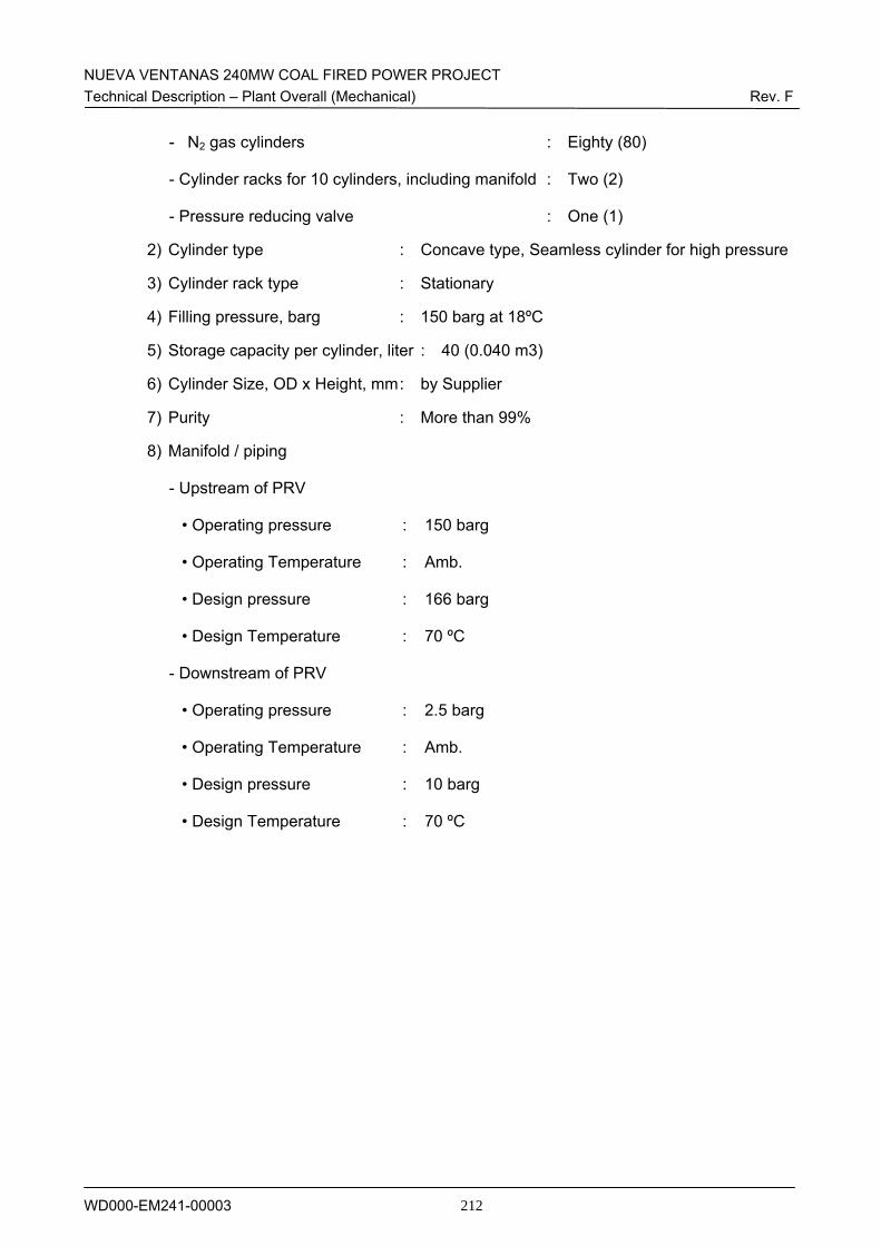
NUEVA VENTANAS 240MW COAL FIRED POWER PROJECT Technical Description – Plant Overall (Mechanical) Rev. F
WD000-EM241-00003 212
- N2 gas cylinders : Eighty (80)
- Cylinder racks for 10 cylinders, including manifold : Two (2)
- Pressure reducing valve : One (1)
2) Cylinder type : Concave type, Seamless cylinder for high pressure
3) Cylinder rack type : Stationary
4) Filling pressure, barg : 150 barg at 18ºC
5) Storage capacity per cylinder, liter : 40 (0.040 m3)
6) Cylinder Size, OD x Height, mm : by Supplier
7) Purity : More than 99%
8) Manifold / piping
- Upstream of PRV
• Operating pressure : 150 barg
• Operating Temperature : Amb.
• Design pressure : 166 barg
• Design Temperature : 70 ºC
- Downstream of PRV
• Operating pressure : 2.5 barg
• Operating Temperature : Amb.
• Design pressure : 10 barg
• Design Temperature : 70 ºC
NUEVA VENTANAS 240MW COAL FIRED POWER PROJECT Technical Description – Plant Overall (Mechanical) Rev. F
WD000-EM241-00003 213
29. HEATING, VENTILATION AND AIR CONDITIONING SYSTEM (4.27)
29.1 Function The functions of heating, ventilation and air conditioning (HVAC) system are :
to control environmental conditions within buildings for comfort of operation and maintenance personnel
to control environmental conditions in buildings within limits for proper operation and protection of equipment and systems
29.2 Design Bases
The HVAC system is designed with the following design bases :
29.2.1 Codes and Standards The HVAC system design is based on the criteria set forth in the following documents and standards:
AABC Associated Air Balancing Council
AMCA Air Moving and Conditioning Association
ANSI American National Standards Institute
AFBMA Anti-Friction Bearing Subcontractors Association
ASHRAE American Society of Heating, Refrigerating and Air Conditioning Engineers
ASME American Society of Mechanical Engineers
ASME Sect IX Welding and Brazing Qualifications
Stand ICS 1.1 Safety Guidelines for Application, Installation and Maintenance of Solid State Controls
ASTM American Society for Testing and Materials
IEEE Institute of Electrical & Electronics Engineers
NEC National Electrical Code (NFPA 70)
NEMA National Electric Subcontractor's Association
NFPA National Fire Protection Association
OSHA Occupational Safety and Health Administration
SMACNA Sheet Metal and Air Conditioning Contractors National Association
SSPC Steel Structures Painting Council
UL Underwriters' Laboratories
KS Korean Industrial Standard
JIS Japanese Industrial Standard
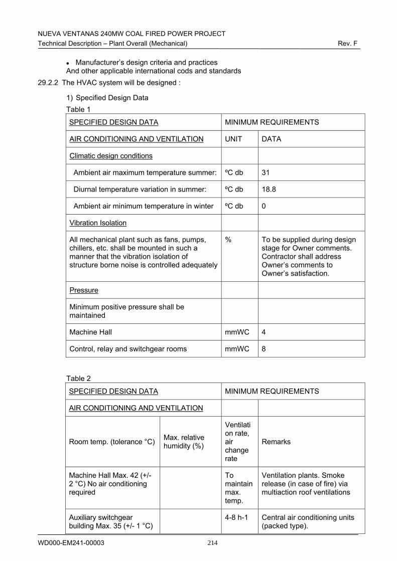
NUEVA VENTANAS 240MW COAL FIRED POWER PROJECT Technical Description – Plant Overall (Mechanical) Rev. F
WD000-EM241-00003 214
Manufacturer’s design criteria and practices And other applicable international cods and standards
29.2.2 The HVAC system will be designed :
1) Specified Design Data Table 1
SPECIFIED DESIGN DATA MINIMUM REQUIREMENTS
AIR CONDITIONING AND VENTILATION UNIT DATA
Climatic design conditions
Ambient air maximum temperature summer: ºC db 31
Diurnal temperature variation in summer: ºC db 18.8
Ambient air minimum temperature in winter ºC db 0
Vibration Isolation
All mechanical plant such as fans, pumps, chillers, etc. shall be mounted in such a manner that the vibration isolation of structure borne noise is controlled adequately
% To be supplied during design stage for Owner comments. Contractor shall address Owner’s comments to Owner’s satisfaction.
Pressure
Minimum positive pressure shall be maintained
Machine Hall mmWC 4
Control, relay and switchgear rooms mmWC 8
Table 2
SPECIFIED DESIGN DATA MINIMUM REQUIREMENTS
AIR CONDITIONING AND VENTILATION
Room temp. (tolerance °C) Max. relative humidity (%)
Ventilation rate, air change rate
Remarks
Machine Hall Max. 42 (+/- 2 °C) No air conditioning required
To maintain max. temp.
Ventilation plants. Smoke release (in case of fire) via multiaction roof ventilations
Auxiliary switchgear building Max. 35 (+/- 1 °C)
4-8 h-1 Central air conditioning units (packed type).
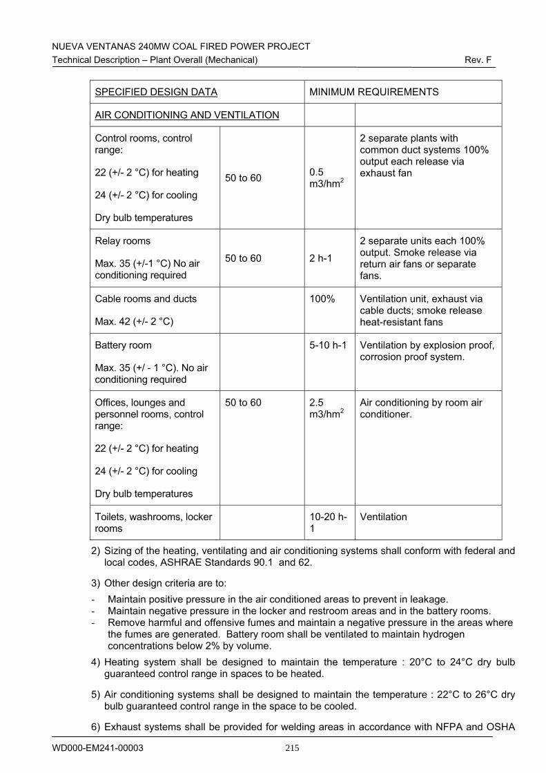
NUEVA VENTANAS 240MW COAL FIRED POWER PROJECT Technical Description – Plant Overall (Mechanical) Rev. F
WD000-EM241-00003 215
SPECIFIED DESIGN DATA MINIMUM REQUIREMENTS
AIR CONDITIONING AND VENTILATION
Control rooms, control range:
22 (+/- 2 °C) for heating
24 (+/- 2 °C) for cooling
Dry bulb temperatures
50 to 60 0.5 m3/hm2
2 separate plants with common duct systems 100% output each release via exhaust fan
Relay rooms
Max. 35 (+/-1 °C) No air conditioning required
50 to 60 2 h-1
2 separate units each 100% output. Smoke release via return air fans or separate fans.
Cable rooms and ducts
Max. 42 (+/- 2 °C)
100% Ventilation unit, exhaust via cable ducts; smoke release heat-resistant fans
Battery room
Max. 35 (+/ - 1 °C). No air conditioning required
5-10 h-1 Ventilation by explosion proof, corrosion proof system.
Offices, lounges and personnel rooms, control range:
22 (+/- 2 °C) for heating
24 (+/- 2 °C) for cooling
Dry bulb temperatures
50 to 60 2.5 m3/hm2
Air conditioning by room air conditioner.
Toilets, washrooms, locker rooms
10-20 h-1
Ventilation
2) Sizing of the heating, ventilating and air conditioning systems shall conform with federal and local codes, ASHRAE Standards 90.1 and 62.
3) Other design criteria are to: - Maintain positive pressure in the air conditioned areas to prevent in leakage. - Maintain negative pressure in the locker and restroom areas and in the battery rooms. - Remove harmful and offensive fumes and maintain a negative pressure in the areas where
the fumes are generated. Battery room shall be ventilated to maintain hydrogen concentrations below 2% by volume.
4) Heating system shall be designed to maintain the temperature : 20°C to 24°C dry bulb guaranteed control range in spaces to be heated.
5) Air conditioning systems shall be designed to maintain the temperature : 22°C to 26°C dry bulb guaranteed control range in the space to be cooled.
6) Exhaust systems shall be provided for welding areas in accordance with NFPA and OSHA
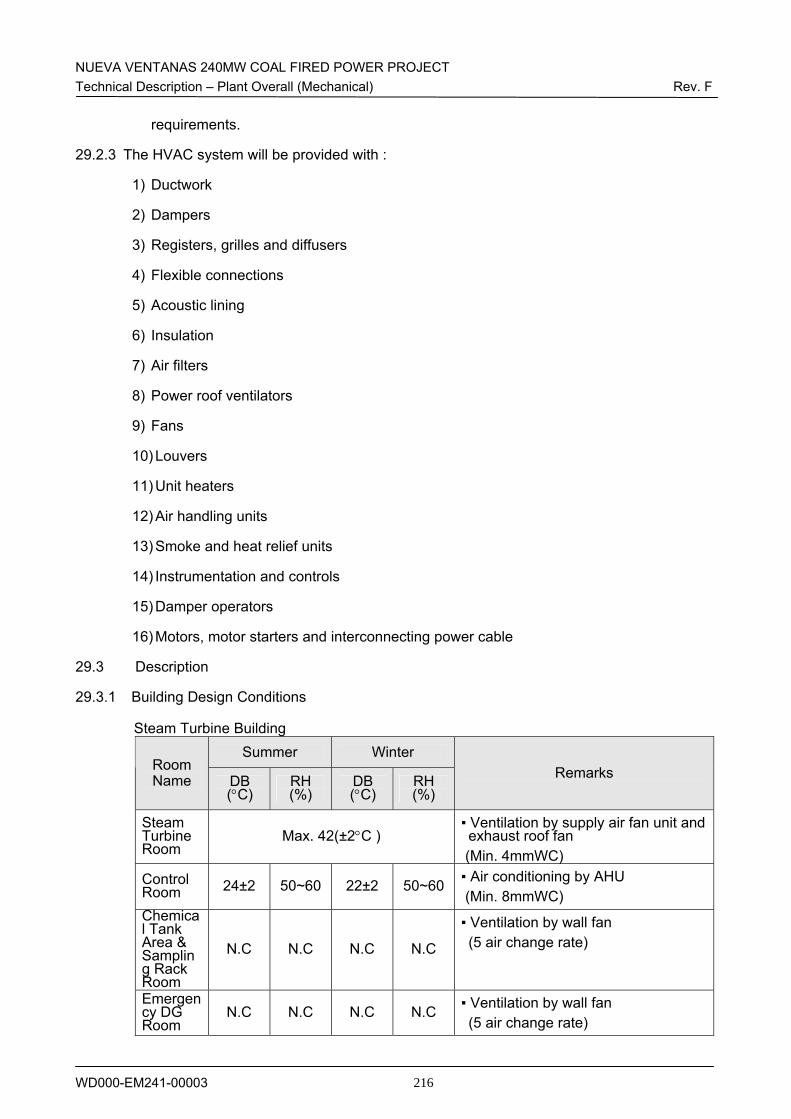
NUEVA VENTANAS 240MW COAL FIRED POWER PROJECT Technical Description – Plant Overall (Mechanical) Rev. F
WD000-EM241-00003 216
requirements.
29.2.3 The HVAC system will be provided with :
1) Ductwork
2) Dampers
3) Registers, grilles and diffusers
4) Flexible connections
5) Acoustic lining
6) Insulation
7) Air filters
8) Power roof ventilators
9) Fans
10) Louvers
11) Unit heaters
12) Air handling units
13) Smoke and heat relief units
14) Instrumentation and controls
15) Damper operators
16) Motors, motor starters and interconnecting power cable
29.3 Description
29.3.1 Building Design Conditions
Steam Turbine Building Summer Winter
Room Name DB
(°C) RH (%)
DB (°C)
RH (%)
Remarks
Steam Turbine Room
Max. 42(±2°C ) ▪ Ventilation by supply air fan unit and exhaust roof fan
(Min. 4mmWC) Control Room 24±2 50~60 22±2 50~60 ▪ Air conditioning by AHU
(Min. 8mmWC) Chemical Tank Area & Sampling Rack Room
N.C N.C N.C N.C
▪ Ventilation by wall fan (5 air change rate)
Emergency DG Room
N.C N.C N.C N.C ▪ Ventilation by wall fan (5 air change rate)
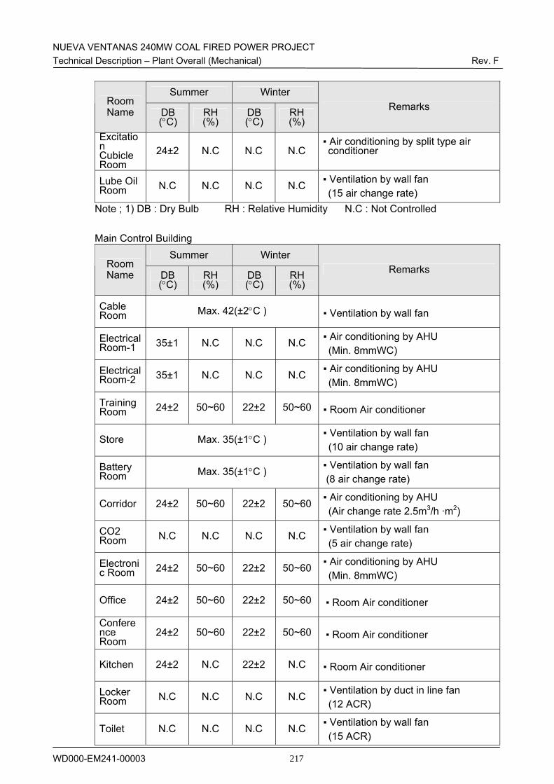
NUEVA VENTANAS 240MW COAL FIRED POWER PROJECT Technical Description – Plant Overall (Mechanical) Rev. F
WD000-EM241-00003 217
Summer Winter Room Name DB
(°C) RH (%)
DB (°C)
RH (%)
Remarks
Excitation Cubicle Room
24±2 N.C N.C N.C ▪ Air conditioning by split type air conditioner
Lube Oil Room N.C N.C N.C N.C ▪ Ventilation by wall fan
(15 air change rate) Note ; 1) DB : Dry Bulb RH : Relative Humidity N.C : Not Controlled
Main Control Building Summer Winter
Room Name DB
(°C) RH (%)
DB (°C)
RH (%)
Remarks
Cable Room Max. 42(±2°C ) ▪ Ventilation by wall fan
Electrical Room-1 35±1 N.C N.C N.C ▪ Air conditioning by AHU
(Min. 8mmWC)
Electrical Room-2 35±1 N.C N.C N.C ▪ Air conditioning by AHU
(Min. 8mmWC)
Training Room 24±2 50~60 22±2 50~60 ▪ Room Air conditioner
Store Max. 35(±1°C ) ▪ Ventilation by wall fan (10 air change rate)
Battery Room Max. 35(±1°C ) ▪ Ventilation by wall fan
(8 air change rate)
Corridor 24±2 50~60 22±2 50~60 ▪ Air conditioning by AHU (Air change rate 2.5m3/h ·m2)
CO2 Room N.C N.C N.C N.C ▪ Ventilation by wall fan
(5 air change rate)
Electronic Room 24±2 50~60 22±2 50~60 ▪ Air conditioning by AHU
(Min. 8mmWC)
Office 24±2 50~60 22±2 50~60 ▪ Room Air conditioner
Conference Room
24±2 50~60 22±2 50~60 ▪ Room Air conditioner
Kitchen 24±2 N.C 22±2 N.C ▪ Room Air conditioner
Locker Room N.C N.C N.C N.C ▪ Ventilation by duct in line fan
(12 ACR)
Toilet N.C N.C N.C N.C ▪ Ventilation by wall fan (15 ACR)
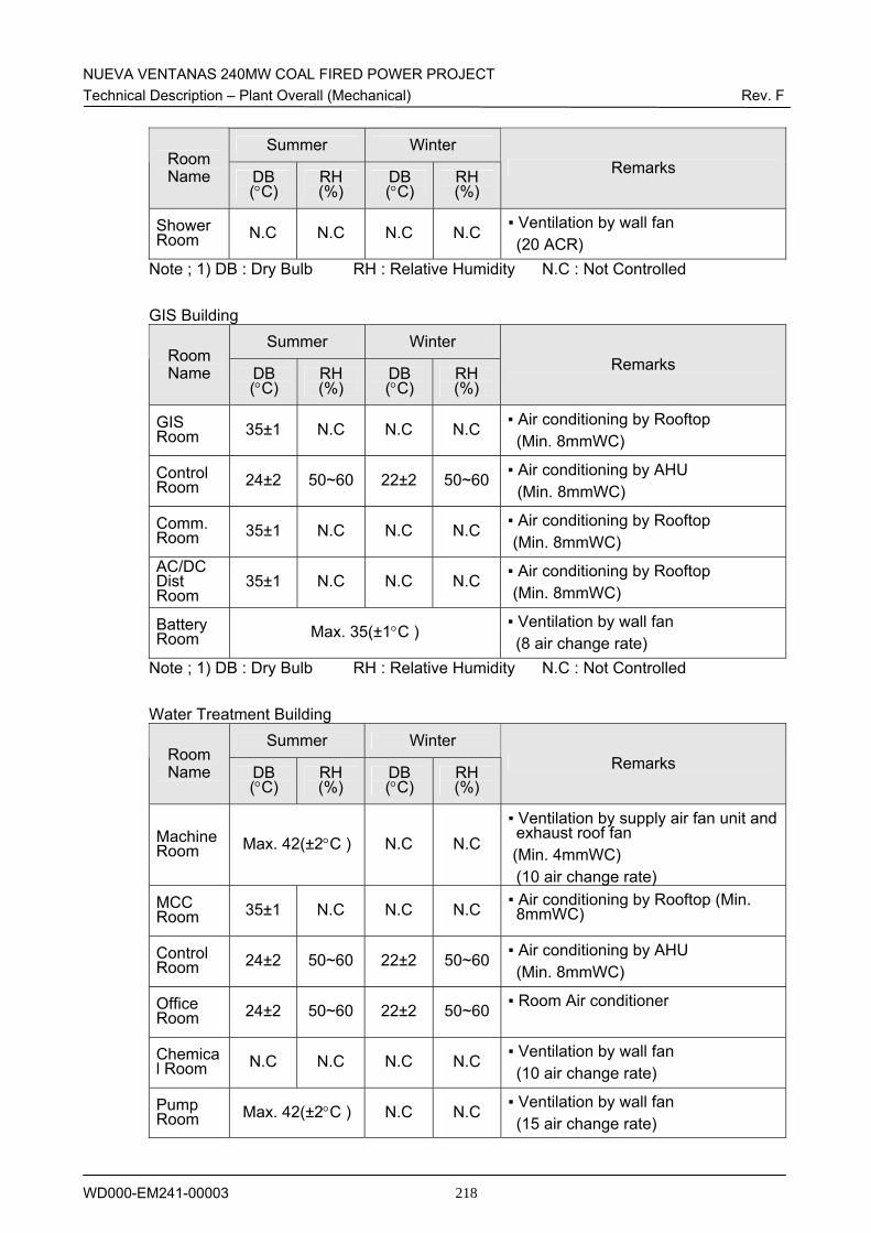
NUEVA VENTANAS 240MW COAL FIRED POWER PROJECT Technical Description – Plant Overall (Mechanical) Rev. F
WD000-EM241-00003 218
Summer Winter Room Name DB
(°C) RH (%)
DB (°C)
RH (%)
Remarks
Shower Room N.C N.C N.C N.C ▪ Ventilation by wall fan
(20 ACR) Note ; 1) DB : Dry Bulb RH : Relative Humidity N.C : Not Controlled
GIS Building Summer Winter
Room Name DB
(°C) RH (%)
DB (°C)
RH (%)
Remarks
GIS Room 35±1 N.C N.C N.C ▪ Air conditioning by Rooftop
(Min. 8mmWC)
Control Room 24±2 50~60 22±2 50~60 ▪ Air conditioning by AHU
(Min. 8mmWC)
Comm. Room 35±1 N.C N.C N.C ▪ Air conditioning by Rooftop
(Min. 8mmWC) AC/DC Dist Room
35±1 N.C N.C N.C ▪ Air conditioning by Rooftop (Min. 8mmWC)
Battery Room Max. 35(±1°C ) ▪ Ventilation by wall fan
(8 air change rate) Note ; 1) DB : Dry Bulb RH : Relative Humidity N.C : Not Controlled
Water Treatment Building Summer Winter
Room Name DB
(°C) RH (%)
DB (°C)
RH (%)
Remarks
Machine Room Max. 42(±2°C ) N.C N.C
▪ Ventilation by supply air fan unit and exhaust roof fan
(Min. 4mmWC) (10 air change rate)
MCC Room 35±1 N.C N.C N.C ▪ Air conditioning by Rooftop (Min.
8mmWC)
Control Room 24±2 50~60 22±2 50~60 ▪ Air conditioning by AHU
(Min. 8mmWC)
Office Room 24±2 50~60 22±2 50~60 ▪ Room Air conditioner
Chemical Room N.C N.C N.C N.C ▪ Ventilation by wall fan
(10 air change rate)
Pump Room Max. 42(±2°C ) N.C N.C ▪ Ventilation by wall fan
(15 air change rate)
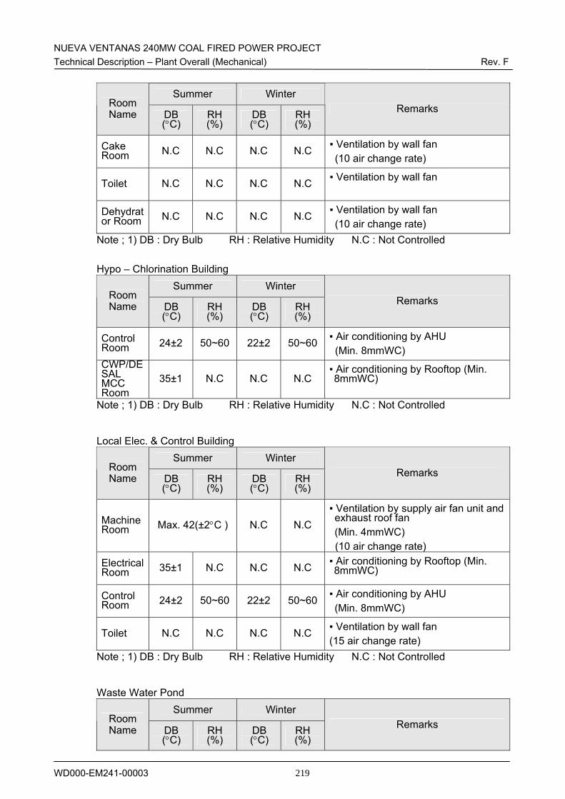
NUEVA VENTANAS 240MW COAL FIRED POWER PROJECT Technical Description – Plant Overall (Mechanical) Rev. F
WD000-EM241-00003 219
Summer Winter Room Name DB
(°C) RH (%)
DB (°C)
RH (%)
Remarks
Cake Room N.C N.C N.C N.C ▪ Ventilation by wall fan
(10 air change rate)
Toilet N.C N.C N.C N.C ▪ Ventilation by wall fan
Dehydrator Room N.C N.C N.C N.C ▪ Ventilation by wall fan
(10 air change rate) Note ; 1) DB : Dry Bulb RH : Relative Humidity N.C : Not Controlled
Hypo – Chlorination Building
Summer Winter Room Name DB
(°C) RH (%)
DB (°C)
RH (%)
Remarks
Control Room 24±2 50~60 22±2 50~60 ▪ Air conditioning by AHU
(Min. 8mmWC) CWP/DESAL MCC Room
35±1 N.C N.C N.C ▪ Air conditioning by Rooftop (Min. 8mmWC)
Note ; 1) DB : Dry Bulb RH : Relative Humidity N.C : Not Controlled
Local Elec. & Control Building Summer Winter
Room Name DB
(°C) RH (%)
DB (°C)
RH (%)
Remarks
Machine Room Max. 42(±2°C ) N.C N.C
▪ Ventilation by supply air fan unit and exhaust roof fan (Min. 4mmWC) (10 air change rate)
Electrical Room 35±1 N.C N.C N.C ▪ Air conditioning by Rooftop (Min.
8mmWC)
Control Room 24±2 50~60 22±2 50~60 ▪ Air conditioning by AHU
(Min. 8mmWC)
Toilet N.C N.C N.C N.C ▪ Ventilation by wall fan (15 air change rate)
Note ; 1) DB : Dry Bulb RH : Relative Humidity N.C : Not Controlled
Waste Water Pond Summer Winter
Room Name DB
(°C) RH (%)
DB (°C)
RH (%)
Remarks
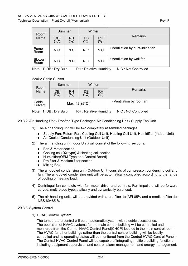
NUEVA VENTANAS 240MW COAL FIRED POWER PROJECT Technical Description – Plant Overall (Mechanical) Rev. F
WD000-EM241-00003 220
Summer Winter Room Name DB
(°C) RH (%)
DB (°C)
RH (%)
Remarks
Pump Room N.C N.C N.C N.C ▪ Ventilation by duct-inline fan
Blower Room N.C N.C N.C N.C ▪ Ventilation by wall fan
Note ; 1) DB : Dry Bulb RH : Relative Humidity N.C : Not Controlled
220kV Cable Culvert Summer Winter
Room Name DB
(°C) RH (%)
DB (°C)
RH (%)
Remarks
Cable Culvert Max. 42(±2°C ) ▪ Ventilation by roof fan
Note ; 1) DB : Dry Bulb RH : Relative Humidity N.C : Not Controlled
29.3.2 Air Handling Unit / Rooftop Type Packaged Air Conditioning Unit / Supply Fan Unit
1) The air handling unit will be two completely assembled packages: Supply Fan, Return Fan, Cooling Coil Unit, Heating Coil Unit, Humidifier (Indoor Unit) Air Cooled Condensing Unit (Outdoor Unit)
2) The air handling unit(Indoor Unit) will consist of the following sections. Fan & Motor section Cooling coil(DX-type) & Heating coil section Humidifier(OEM Type and Control Board) Pre filter & Medium filter section Mixing Box
3) The air-cooled condensing unit (Outdoor Unit) consists of compressor, condensing coil and fan. The air-cooled condensing unit will be automatically controlled according to the range of cooling or heating load.
4) Centrifugal fan complete with fan motor drive, and controls. Fan impellers will be forward curved, multi-blade type, statically and dynamically balanced.
5) The air handling units will be provided with a pre-filter for AFI 85% and a medium filter for NBS 80~85 % .
29.3.3 System Control
1) HVAC Control System The temperature control will be an automatic system with electric accessories. The operation of HVAC systems for the main control building will be controlled and monitored from the Central HVAC Control Panel(CHCP) located in the main control room. The HVAC for other buildings rather than the central control building will be locally controlled and its operating status will be monitored from the Central HVAC Control Panel. The Central HVAC Control Panel will be capable of integrating multiple building functions including equipment supervision and control, alarm management and energy management.
NUEVA VENTANAS 240MW COAL FIRED POWER PROJECT Technical Description – Plant Overall (Mechanical) Rev. F
WD000-EM241-00003 221
HVAC control system will be controlled in connection with fire fighting system. In case of fire, smoke detectors will shut down the air handling unit main fan and close smoke dampers in the ductwork. After the fire has been extinguished, the system will be manually turned on to provide positive smoke evacuation by actuation of a strategically located smoke evacuation switch which switches the A/C unit exhaust fan from normal power to emergency power direct to the fan motor bypassing the normal control system. At the same time, the ductwork smoke dampers, fresh air dampers and exhaust air dampers open up fully and return air damper closes fully, thereby allowing the exhaust air dampers open up fully and return air damper closes fully, thereby allowing the exhaust fan to “draw in” fresh air through the air handling unit into the smoke laden environment and “draw out” smoke. This procedure will keep the smoke laden at a negative pressure relative to adjacent areas. Once the smoke evacuation has been satisfactorily accomplished, the smoke evacuation switch will return to normal position and normal A/C system operation returns.
2) Control and monitoring in the central control room
- Display measured values, parameters, time status functions
- Adjust setpoints and parameters functions
- Set the time and date functions
- Common alarm function of HVAC local control panel