2080-rm002a-en-e micrologix 1000 controllers to micro800 ......• micrologix 1000 to micro800...
TRANSCRIPT

Migration Guide
(Catalog Number 2080 Bulletin)
MicroLogix 1000 Controllers to Micro800 Controllers
Important User Information
Solid-state equipment has operational characteristics differing from those of electromechanical equipment. Safety Guidelines for the Application, Installation and Maintenance of Solid State Controls (publication SGI-1.1 available from your local Rockwell Automation® sales office or online at http://www.rockwellautomation.com/literature/) describes some important differences between solid-state equipment and hard-wired electromechanical devices. Because of this difference, and also because of the wide variety of uses for solid-state equipment, all persons responsible for applying this equipment must satisfy themselves that each intended application of this equipment is acceptable.
In no event will Rockwell Automation, Inc. be responsible or liable for indirect or consequential damages resulting from the use or application of this equipment.
The examples and diagrams in this manual are included solely for illustrative purposes. Because of the many variables and requirements associated with any particular installation, Rockwell Automation, Inc. cannot assume responsibility or liability for actual use based on the examples and diagrams.
No patent liability is assumed by Rockwell Automation, Inc. with respect to use of information, circuits, equipment, or software described in this manual.
Reproduction of the contents of this manual, in whole or in part, without written permission of Rockwell Automation, Inc., is prohibited.
Throughout this manual, when necessary, we use notes to make you aware of safety considerations.
Allen-Bradley, Rockwell Software, Rockwell Automation, MicroLogix, Micro800, Micro810, Micro820, Micro830, Micro850, Connected Components Workbench, RSLogix, and SLC are trademarks of Rockwell Automation, Inc.
Trademarks not belonging to Rockwell Automation are property of their respective companies.
WARNING: Identifies information about practices or circumstances that can cause an explosion in a hazardous environment, which may lead to personal injury or death, property damage, or economic loss.
ATTENTION: Identifies information about practices or circumstances that can lead to personal injury or death, property damage, or economic loss. Attentions help you identify a hazard, avoid a hazard, and recognize the consequence.
SHOCK HAZARD: Labels may be on or inside the equipment, for example, a drive or motor, to alert people that dangerous voltage may be present.
BURN HAZARD: Labels may be on or inside the equipment, for example, a drive or motor, to alert people that surfaces may reach dangerous temperatures.
IMPORTANT Identifies information that is critical for successful application and understanding of the product.

Table of Contents
Preface About This Publication. . . . . . . . . . . . . . . . . . . . . . . . . . . . . . . . . . . . . . . . . . . . . 7Audience . . . . . . . . . . . . . . . . . . . . . . . . . . . . . . . . . . . . . . . . . . . . . . . . . . . . . . . . . . 7Required Software . . . . . . . . . . . . . . . . . . . . . . . . . . . . . . . . . . . . . . . . . . . . . . . . . 7Additional Resources . . . . . . . . . . . . . . . . . . . . . . . . . . . . . . . . . . . . . . . . . . . . . . . 8
Chapter 1Micro800 Controller Overview Controller Dimensions . . . . . . . . . . . . . . . . . . . . . . . . . . . . . . . . . . . . . . . . . . . 10
MicroLogix 1000 Controllers . . . . . . . . . . . . . . . . . . . . . . . . . . . . . . . . . 10Micro820 Controllers . . . . . . . . . . . . . . . . . . . . . . . . . . . . . . . . . . . . . . . . 11Micro830 Controllers – 10 and 16-Point Controllers . . . . . . . . . . . 12Micro830 Controllers – 24 and 48-Point Controllers . . . . . . . . . . . 13
Feature and Specification Comparison . . . . . . . . . . . . . . . . . . . . . . . . . . . . . 14
Chapter 2Select a Suitable Micro800 Controller Convert to a Micro820 Controller. . . . . . . . . . . . . . . . . . . . . . . . . . . . . . . . . 17
Convert to a Micro830 Controller. . . . . . . . . . . . . . . . . . . . . . . . . . . . . . . . . 18Wiring Configuration . . . . . . . . . . . . . . . . . . . . . . . . . . . . . . . . . . . . . . . . . . . . 18
MicroLogix 1000 Controller Wiring . . . . . . . . . . . . . . . . . . . . . . . . . . . 19Micro820 Controller Wiring . . . . . . . . . . . . . . . . . . . . . . . . . . . . . . . . . . 28Micro830 Controller Wiring . . . . . . . . . . . . . . . . . . . . . . . . . . . . . . . . . . 29
Chapter 3Convert an RSLogix 500 Project to a Connected Components Workbench Project
Overview . . . . . . . . . . . . . . . . . . . . . . . . . . . . . . . . . . . . . . . . . . . . . . . . . . . . . . . . 33Before You Begin . . . . . . . . . . . . . . . . . . . . . . . . . . . . . . . . . . . . . . . . . . . . . . . . 34What You Need . . . . . . . . . . . . . . . . . . . . . . . . . . . . . . . . . . . . . . . . . . . . . . . . . 34Generate an Existing RSLogix 500 Project Report. . . . . . . . . . . . . . . . . . . 34Create Equivalent Program Files in Connected Components Workbench. . . . . . . . . . . . . . . . . . . . . . . . . . . . . . 35
Configure Interrupts on a Micro800 Controller (Example) . . . . . . 38Create Representative Data Files in Connected Components Workbench. . . . . . . . . . . . . . . . . . . . . . . . . . . . . . 40
Set Up Embedded I/O Variables. . . . . . . . . . . . . . . . . . . . . . . . . . . . . . . 40Substitute Binary (B3) and Integer (N7) Data Files. . . . . . . . . . . . . . 41Set Up Variables for Index Addressing . . . . . . . . . . . . . . . . . . . . . . . . . 42Set Up High Speed Counter (HSC) Instruction Variables . . . . . . . 42
Create an Equivalent Program in Connected Components Workbench. . . . . . . . . . . . . . . . . . . . . . . . . . . . . . 44
Basic Ladder Programming Tasks . . . . . . . . . . . . . . . . . . . . . . . . . . . . . . 44Replicate the Ladder Diagram . . . . . . . . . . . . . . . . . . . . . . . . . . . . . . . . . 51Program Index Addressing . . . . . . . . . . . . . . . . . . . . . . . . . . . . . . . . . . . . 52Program High Speed Counter (HSC) Instruction. . . . . . . . . . . . . . . 55Program Timer On Delay (TON) Instruction . . . . . . . . . . . . . . . . . . 57
Build and Test the Connected Components Workbench Project. . . . . 59MicroLogix to Micro800 Converter Tool . . . . . . . . . . . . . . . . . . . . . . . . . . 61
Rockwell Automation Publication 2080-RM002A-EN-E - July 2015 3

Table of Contents
Download and Install the MicroLogix to Micro800 Converter Tool. . . . . . . . . . . . . . . . . . . . . . . . . . . . . . . . . . . . . . . . . . . . . . . 62Save the RSLogix 500 Project as an SLC File . . . . . . . . . . . . . . . . . . . . 63Run the MicroLogix to Micro800 Converter Tool . . . . . . . . . . . . . . 65Convert the SLC File to a Connected Components Workbench Project . . . . . . . . . . . . . . . . . . . . . . . . . . . . . . . . . . . . . . . . . . . . . . . . . . . . . . . 66Notes on the Converted Pick and Place Application . . . . . . . . . . . . . 66
Chapter 4RLL Instruction Mapping Overview . . . . . . . . . . . . . . . . . . . . . . . . . . . . . . . . . . . . . . . . . . . . . . . . . . . . . . . . 69
Definitions, Acronyms, and Abbreviations . . . . . . . . . . . . . . . . . . . . . . . . . 69Bit Shift . . . . . . . . . . . . . . . . . . . . . . . . . . . . . . . . . . . . . . . . . . . . . . . . . . . . . . . . . 70
BSL . . . . . . . . . . . . . . . . . . . . . . . . . . . . . . . . . . . . . . . . . . . . . . . . . . . . . . . . . 70BSR . . . . . . . . . . . . . . . . . . . . . . . . . . . . . . . . . . . . . . . . . . . . . . . . . . . . . . . . . 72
Communication . . . . . . . . . . . . . . . . . . . . . . . . . . . . . . . . . . . . . . . . . . . . . . . . . 74MSG . . . . . . . . . . . . . . . . . . . . . . . . . . . . . . . . . . . . . . . . . . . . . . . . . . . . . . . . 74
Comparison . . . . . . . . . . . . . . . . . . . . . . . . . . . . . . . . . . . . . . . . . . . . . . . . . . . . . 76EQU . . . . . . . . . . . . . . . . . . . . . . . . . . . . . . . . . . . . . . . . . . . . . . . . . . . . . . . . 77NEQ . . . . . . . . . . . . . . . . . . . . . . . . . . . . . . . . . . . . . . . . . . . . . . . . . . . . . . . . 78LES. . . . . . . . . . . . . . . . . . . . . . . . . . . . . . . . . . . . . . . . . . . . . . . . . . . . . . . . . . 80LEQ . . . . . . . . . . . . . . . . . . . . . . . . . . . . . . . . . . . . . . . . . . . . . . . . . . . . . . . . . 81GRT . . . . . . . . . . . . . . . . . . . . . . . . . . . . . . . . . . . . . . . . . . . . . . . . . . . . . . . . 83GEQ . . . . . . . . . . . . . . . . . . . . . . . . . . . . . . . . . . . . . . . . . . . . . . . . . . . . . . . . 84LIM . . . . . . . . . . . . . . . . . . . . . . . . . . . . . . . . . . . . . . . . . . . . . . . . . . . . . . . . . 86
Control. . . . . . . . . . . . . . . . . . . . . . . . . . . . . . . . . . . . . . . . . . . . . . . . . . . . . . . . . . 89JMP . . . . . . . . . . . . . . . . . . . . . . . . . . . . . . . . . . . . . . . . . . . . . . . . . . . . . . . . . 89LBL . . . . . . . . . . . . . . . . . . . . . . . . . . . . . . . . . . . . . . . . . . . . . . . . . . . . . . . . . 90RET . . . . . . . . . . . . . . . . . . . . . . . . . . . . . . . . . . . . . . . . . . . . . . . . . . . . . . . . . 91SUS . . . . . . . . . . . . . . . . . . . . . . . . . . . . . . . . . . . . . . . . . . . . . . . . . . . . . . . . . 92TND . . . . . . . . . . . . . . . . . . . . . . . . . . . . . . . . . . . . . . . . . . . . . . . . . . . . . . . . 93
I/O Related Interrupt . . . . . . . . . . . . . . . . . . . . . . . . . . . . . . . . . . . . . . . . . . . . 95IIM. . . . . . . . . . . . . . . . . . . . . . . . . . . . . . . . . . . . . . . . . . . . . . . . . . . . . . . . . . 95IOM. . . . . . . . . . . . . . . . . . . . . . . . . . . . . . . . . . . . . . . . . . . . . . . . . . . . . . . . . 97
Selectable Timed Interrupts . . . . . . . . . . . . . . . . . . . . . . . . . . . . . . . . . . . . . . . 99STD . . . . . . . . . . . . . . . . . . . . . . . . . . . . . . . . . . . . . . . . . . . . . . . . . . . . . . . . . 99STE . . . . . . . . . . . . . . . . . . . . . . . . . . . . . . . . . . . . . . . . . . . . . . . . . . . . . . . . 100STS. . . . . . . . . . . . . . . . . . . . . . . . . . . . . . . . . . . . . . . . . . . . . . . . . . . . . . . . . 102
File Manipulation . . . . . . . . . . . . . . . . . . . . . . . . . . . . . . . . . . . . . . . . . . . . . . . 104COP . . . . . . . . . . . . . . . . . . . . . . . . . . . . . . . . . . . . . . . . . . . . . . . . . . . . . . . 104
Math . . . . . . . . . . . . . . . . . . . . . . . . . . . . . . . . . . . . . . . . . . . . . . . . . . . . . . . . . . . 106ADD . . . . . . . . . . . . . . . . . . . . . . . . . . . . . . . . . . . . . . . . . . . . . . . . . . . . . . . 107SUB . . . . . . . . . . . . . . . . . . . . . . . . . . . . . . . . . . . . . . . . . . . . . . . . . . . . . . . . 109MUL . . . . . . . . . . . . . . . . . . . . . . . . . . . . . . . . . . . . . . . . . . . . . . . . . . . . . . . 111DIV . . . . . . . . . . . . . . . . . . . . . . . . . . . . . . . . . . . . . . . . . . . . . . . . . . . . . . . . 113DDV . . . . . . . . . . . . . . . . . . . . . . . . . . . . . . . . . . . . . . . . . . . . . . . . . . . . . . . 115NEG . . . . . . . . . . . . . . . . . . . . . . . . . . . . . . . . . . . . . . . . . . . . . . . . . . . . . . . 117SQR . . . . . . . . . . . . . . . . . . . . . . . . . . . . . . . . . . . . . . . . . . . . . . . . . . . . . . . . 118
4 Rockwell Automation Publication 2080-RM002A-EN-E - July 2015

Table of Contents
Move and Logical . . . . . . . . . . . . . . . . . . . . . . . . . . . . . . . . . . . . . . . . . . . . . . . 120MOV . . . . . . . . . . . . . . . . . . . . . . . . . . . . . . . . . . . . . . . . . . . . . . . . . . . . . . 121AND . . . . . . . . . . . . . . . . . . . . . . . . . . . . . . . . . . . . . . . . . . . . . . . . . . . . . . . 123XOR . . . . . . . . . . . . . . . . . . . . . . . . . . . . . . . . . . . . . . . . . . . . . . . . . . . . . . . 125OR. . . . . . . . . . . . . . . . . . . . . . . . . . . . . . . . . . . . . . . . . . . . . . . . . . . . . . . . . 127NOT. . . . . . . . . . . . . . . . . . . . . . . . . . . . . . . . . . . . . . . . . . . . . . . . . . . . . . . 129
Relay Type . . . . . . . . . . . . . . . . . . . . . . . . . . . . . . . . . . . . . . . . . . . . . . . . . . . . . 130XIC . . . . . . . . . . . . . . . . . . . . . . . . . . . . . . . . . . . . . . . . . . . . . . . . . . . . . . . . 130XIO. . . . . . . . . . . . . . . . . . . . . . . . . . . . . . . . . . . . . . . . . . . . . . . . . . . . . . . . 131OTE . . . . . . . . . . . . . . . . . . . . . . . . . . . . . . . . . . . . . . . . . . . . . . . . . . . . . . . 132OTL . . . . . . . . . . . . . . . . . . . . . . . . . . . . . . . . . . . . . . . . . . . . . . . . . . . . . . . 134OTU. . . . . . . . . . . . . . . . . . . . . . . . . . . . . . . . . . . . . . . . . . . . . . . . . . . . . . . 135OSR. . . . . . . . . . . . . . . . . . . . . . . . . . . . . . . . . . . . . . . . . . . . . . . . . . . . . . . . 137
Timer and Counter . . . . . . . . . . . . . . . . . . . . . . . . . . . . . . . . . . . . . . . . . . . . . 139CTD . . . . . . . . . . . . . . . . . . . . . . . . . . . . . . . . . . . . . . . . . . . . . . . . . . . . . . . 140CTU . . . . . . . . . . . . . . . . . . . . . . . . . . . . . . . . . . . . . . . . . . . . . . . . . . . . . . . 142TON. . . . . . . . . . . . . . . . . . . . . . . . . . . . . . . . . . . . . . . . . . . . . . . . . . . . . . . 144TOF . . . . . . . . . . . . . . . . . . . . . . . . . . . . . . . . . . . . . . . . . . . . . . . . . . . . . . . 147RTO . . . . . . . . . . . . . . . . . . . . . . . . . . . . . . . . . . . . . . . . . . . . . . . . . . . . . . . 150High Speed Counter. . . . . . . . . . . . . . . . . . . . . . . . . . . . . . . . . . . . . . . . . 152
Miscellaneous. . . . . . . . . . . . . . . . . . . . . . . . . . . . . . . . . . . . . . . . . . . . . . . . . . . 155Notes on Unsupported RSLogix 500 Instruction Set . . . . . . . . . . . 155
Appendix AOriginal and Converted Pick and Place Ladder Diagrams
RSLogix 500 Pick and Place Ladder Diagram . . . . . . . . . . . . . . . . . . . . . . 157Connected Components Workbench Ladder Diagram (Converter Tool) . . . . . . . . . . . . . . . . . . . . . . . . . . . . . . . . . . . . . . . . . . . . . . . 159
Tool Conversion Results . . . . . . . . . . . . . . . . . . . . . . . . . . . . . . . . . . . . . 161Connected Components Workbench Ladder Diagram (Manual Conversion) . . . . . . . . . . . . . . . . . . . . . . . . . . . . . . . . . . . . . . . . . . . 164
Rockwell Automation Publication 2080-RM002A-EN-E - July 2015 5

Table of Contents
Notes:
6 Rockwell Automation Publication 2080-RM002A-EN-E - July 2015

Preface
About This Publication This document serves as a guide for replacing your existing MicroLogix™ 1000 controller with either a Micro820™ controller or a Micro830® controller. Micro820 and Micro830 controllers are included in the Micro800® family of controllers.
Descriptions, wiring diagrams, as well as information about the dimensions, features, and specifications of the controllers are provided to help you select the appropriate Micro800 controller to replace your MicroLogix 1000 controller.
After you have selected a suitable controller, refer to the conversion walk-through in Chapter 3 to become familiar with the basic steps that a user needs to perform with Micro820 and Micro830 controllers.
Audience The intended audience of this document is users of MicroLogix 1000 controllers who are converting to either a Micro820 or Micro830 controller, and who are familiar with the RSLogix™ 500 programming software. Knowledge of programming in ladder language is expected to be able to program Micro800 systems effectively.
Required Software To complete the steps in this document, the following software are required:
• Connected Components Workbench™ revision 8 and later
Connected Components Workbench is the main programming software for Micro800 systems. It provides a choice of IEC 61131-3 programming languages (ladder diagram, function block diagram, structured text) with user-defined function block support that optimizes machine control.
You need the Connected Components Workbench software to write your ladder diagram, function block diagram, or structured text programs, to execute the programs, and to see the results.
• MicroLogix 1000 to Micro800 Converter Tool
The MicroLogix to Micro800 Converter tool only supports conversion from MicroLogix 1000 controllers to Micro800 series controllers. This release is supported only as an addition to Connected Components Workbench, revision 8 or later.
The MicroLogix to Micro800 Converter tool converts an RSLogix 500 project (.SLC) file into a Connected Components Workbench project. This tool provides conversion for ladder diagram (LD) programming languages in the MicroLogix processor.
Rockwell Automation Publication 2080-RM002A-EN-E - July 2015 7

Preface
The conversion tool can convert most RSLogix 500 instruction blocks. However, you may need to modify converted function blocks in Connected Components Workbench to ensure it performs properly. All information that require additional user attention is logged in a conversion report so that you can make the required changes.
The converter tool is available for download at:http://www.rockwellautomation.com/rockwellautomation/support/pcdc.page
Additional Resources These documents contain additional information concerning related products from Rockwell Automation.
You can view or download publications athttp:/www.rockwellautomation.com/literature/. To order paper copies of technical documentation, contact your local Allen-Bradley distributor or Rockwell Automation sales representative.
Resource Description
Micro800 Programmable Controllers General Instructions, publication 2080-RM001
Provides reference information about the instruction set available for developing programs for use in Micro800 Control systems.
Micro820 Programmable Controllers User Manual, publication 2080-UM005
A more detailed description of how to install and use your Micro820 programmable controllers.
Micro830 and Micro850 Programmable Controllers User Manual, publication 2080-UM002
A more detailed description of how to install and use your Micro830 and Micro850 programmable controllers.
Micro800 Plug-in Modules User Manual,publication 2080-UM004
Description of features, installation, wiring, and specifications for the Micro800 plug-in modules.
Micro800 and Connected Components Workbench Getting Started Guide, publication 2080-QR001
Provides information about basic Micro800 programmable controllers and Connected Component Workbench functions.
Micro800 and Connected Components Workbench Application Guide, publication 2080-QR002
Provides information about Micro800 programmable controllers and Connected Component Workbench functions.
Industrial Automation Wiring and Grounding Guidelines, publication 1770-4.1
More information on proper wiring and grounding techniques.
Connected Components Workbench Online Help Online Help that provides a description of the different elements of the Connected Components Workbench software.
8 Rockwell Automation Publication 2080-RM002A-EN-E - July 2015

Chapter 1
Micro800 Controller Overview
Micro800 controllers are designed for low-cost, standalone machines. These economical small-size programmable logic controllers (PLCs) are available in different form factors based on the number of I/O points embedded in the base, with a range of features intended to address different requirements.
The Micro800 family shares programming environment, accessories, and plug-ins that allow machine builders to personalize the controller for specific capabilities.
Micro810® controllers function as a smart relay with high current relay outputs, but with the programming capabilities of a micro PLC. The Micro810 controllers come in a 12-point form factor.
Micro820 controllers are specifically designed for smaller standalone machines and remote automation projects. They have embedded Ethernet and serial ports and microSD™ slots for data logging and recipe management. These controllers come as 20-point form factors that can accommodate up to two plug-in modules. They also support the Micro800 Remote LCD (2080-REMLCD) module for easier configuration of settings such as IP address. The Remote LCD module can also function as a simple IP65 text display.
Micro830 controllers are designed for standalone machine control applications. They have flexible communications and I/O capabilities with up to five plug-ins. They come as a 10-, 16-, 24-, or 48-point form factors.
Micro850® expandable controllers are designed for applications that require more digital and analog I/O or higher performance analog I/O. They can support up to four expansion I/O. Micro850 controllers include additional communication connection options through an embedded 10/100 Base-T Ethernet port.
Several Micro830 and Micro850 controllers support basic positioning through embedded pulse train outputs (PTO).
These controllers also allow you to configure up to six high speed counters (HSC), and choose from nine HSC operation modes. HSC is supported on all Micro830 and Micro850 modules, except on the 2080-LCxx-xxAWB module. PTO is only supported on Micro830 and Micro850 catalog numbers that end in BB or VB, for example the 2080-LCxxxxxx catalog number.
Rockwell Automation Publication 2080-RM002A-EN-E - July 2015 9

Chapter 1 Micro800 Controller Overview
Controller Dimensions
The following section illustrates MicroLogix 1000 controllers and their counterparts from the Micro800 family.
MicroLogix 1000 Controllers
MicroLogix 1000 Controller Dimensions
Controller Catalog Number A: mm (in.) B: mm (in.) C: mm (in.)
1761-L10BWA 120 (4.72) 73 (2.87) 80 (3.15)
1761-L16AWA 133 (5.24)
1761-L16BWA 120 (4.72)
1761-L16NWA
1761-L20AWA-5A 133 (5.24)
1761-L20BWA-5A 200 (787)
1761-L32AWA
1761-L32BWA
1761-L32AAA
1761-L10BWB 120 (4.72) 40 (1.57)
1761-L10BXB
1761-L16BBB
1761-L16BWB
1761-L16NWB
1761-L20BWB-5A 200 (7.87)
1761-L32BBB
1761-L32BWB
B
CC
A
10 Rockwell Automation Publication 2080-RM002A-EN-E - July 2015

Micro800 Controller Overview Chapter 1
Micro820 Controllers
Micro820 Controller Dimensions
Controller Catalog Number Width: mm (in.) Height: mm (in.) Depth: mm (in.)
2080-LC20-20AWB/ R 104 (4.09) 90 (3.54) 75 (2.95)
2080-LC20-20QWB/ R
2080-LC20-20QBB/ R
90 (3.54)
104 (4.09)) 75 (2.95)
Rockwell Automation Publication 2080-RM002A-EN-E - July 2015 11

Chapter 1 Micro800 Controller Overview
Micro830 Controllers – 10 and 16-Point Controllers
Micro830 10 and 16-Point Controller Dimensions
Controller Catalog Number Width: mm (in.) Height: mm (in.) Depth: mm (in.)
2080-LC30-10QWB 100 (3.94) 90 (3.54) 80 (3.15)
2080-LC30-10QVB
2080-LC30-16AWB
2080-LC30-16QWB
2080-LC30-16QVB
100 (3.94)
90 (3.54)
80 (3.15)
12 Rockwell Automation Publication 2080-RM002A-EN-E - July 2015

Micro800 Controller Overview Chapter 1
Micro830 Controllers – 24 and 48-Point Controllers
Micro830 24 and 48-Point Controller Dimensions
Controller Catalog Number Width: mm (in.) Height: mm (in.) Depth: mm (in.)
2080-LC30-24QWB 150 (5.91) 90 (3.54) 80 (3.15)
2080-LC30-24QVB
2080-LC30-24QBB
2080-LC30-48AWB 210 (8.27)
2080-LC30-48QWB
2080-LC30-48QVB
2080-LC30-48QBB
Micro830 24-Point Controllers Micro830 48-Point Controllers
150 (5.91) 80 (3.15)
90 (3.54)
80 (3.15)
90 (3.54)
210 (8.27)
Rockwell Automation Publication 2080-RM002A-EN-E - July 2015 13

Chapter 1 Micro800 Controller Overview
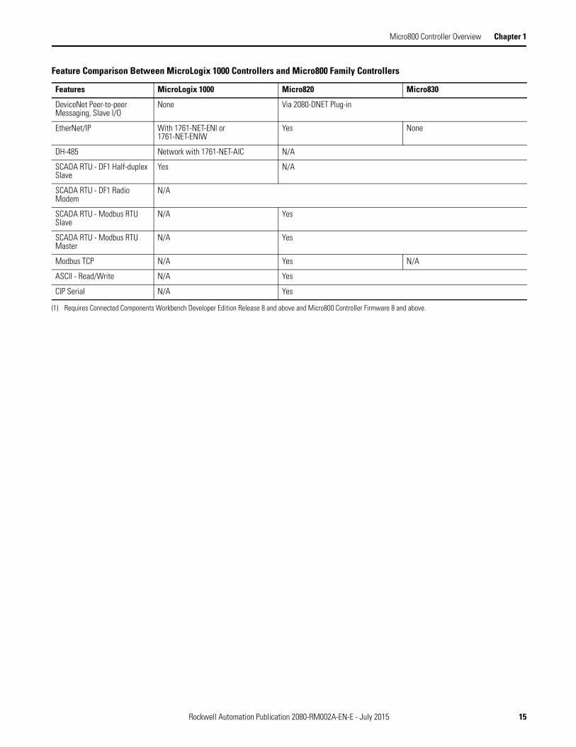
Feature and Specification Comparison
The following table shows the feature and specification differences of the MicroLogix 1000 controllers and Micro800 family controllers.
Feature Comparison Between MicroLogix 1000 Controllers and Micro800 Family Controllers
Features MicroLogix 1000 Micro820 Micro830
Memory
Memory (in user words)User program/User data
1 KB combined(preconfigured)
10 K/ 20 KB 4 K/8 KB (10/16 point)10 K/ 20 KB (24/48 point)
Memory module (for program backup and transport)
Through hand-held programmer Via microSD card Via plug-in module, 2080-MEMBAK-RTC
Run Mode Change None Yes(1)
Inputs/ Outputs
Embedded Digital I/O, max 32 19 48
Embedded Analog I/O Two current and Two voltage inputs with one current or voltage output on 20 pt. controllers
One 0…10V analog outputFour 24V DC digital inputs can be configured as 0…10V analog inputs (DC input models only) and via plug-in modules
Via plug-in modules
Expansion I/O Supported None
Thermocouple/ RTD None Via plug-in module, 2080-RTD2, 2080-TC2
Networked Expansion I/O, max None Via plug-in module, 2080-DNET20, up to 20 nodes for I/O operation
Added Functionality
Trim potentiometers None Via plug-in module, 2080-TRIMPOT6
PID None Yes (number limited only by memory)
High Speed Counters (embedded)
One @ 6.6 kHz(Not supported on AC Input models)
Via plug-in module, 2080-MOT-HSC Two @ 10/16 points, Four @ 24 points, Six @ 48 points(Not supported on AC Input models)
Motion: PTO/ PWM Support None PWM onlyOne @ 5 kHz(Not supported on Relay Output models)
One @ 10/16 points,Two @ 24 points,Three @ 48 points(Not supported on Relay Output models)
Real-Time Clock None Embedded Via plug-in module, 2080-MEMBAK-RTC
Recipe Storage None Via microSD card None
Data Logging None Via microSD card None
Floating Point Math None 32 bit and 64 bit 32 bit and 64 bit
Operating Power
120/240 V AC Yes Via Power Supply module, 2080-PS120-240VAC
24V DC Yes
Communication
RS-232 Ports 8-pin mini DIN Embedded RS232/RS485Serial Port Combo
8-pin mini DIN RS232/RS485 Serial Port Combo
14 Rockwell Automation Publication 2080-RM002A-EN-E - July 2015
Micro800 Controller Overview Chapter 1
DeviceNet Peer-to-peer Messaging, Slave I/O
None Via 2080-DNET Plug-in
EtherNet/IP With 1761-NET-ENI or 1761-NET-ENIW
Yes None
DH-485 Network with 1761-NET-AIC N/A
SCADA RTU - DF1 Half-duplex Slave
Yes N/A
SCADA RTU - DF1 Radio Modem
N/A
SCADA RTU - Modbus RTU Slave
N/A Yes
SCADA RTU - Modbus RTU Master
N/A Yes
Modbus TCP N/A Yes N/A
ASCII - Read/Write N/A Yes
CIP Serial N/A Yes
(1) Requires Connected Components Workbench Developer Edition Release 8 and above and Micro800 Controller Firmware 8 and above.
Feature Comparison Between MicroLogix 1000 Controllers and Micro800 Family Controllers
Features MicroLogix 1000 Micro820 Micro830
Rockwell Automation Publication 2080-RM002A-EN-E - July 2015 15

Chapter 1 Micro800 Controller Overview
Notes:
16 Rockwell Automation Publication 2080-RM002A-EN-E - July 2015

Chapter 2
Select a Suitable Micro800 Controller
This section helps you determine how to select and wire a suitable Micro800 controller (either a Micro820 or a Micro830 controller) for your existing MicroLogix 1000 controller wiring configuration.
Note that any MicroLogix 1000 DC input can be configured as sinking or sourcing depending on how the DC COM terminal is wired.
Convert to a Micro820 Controller
Refer to the following table to see the suitable Micro820 controller to replace your MicroLogix 1000 controller. Click on a catalog number to see the applicable wiring configuration.
IMPORTANT For applications that require High Speed Counter (HSC) function, migrate to a Micro830 controller. Refer to Convert to a Micro830 Controller on page 18 for more information.
MicroLogix 1000 Micro820 Plug-in / Accessories
1761-L10BWB 1761-L16BWB 1761-L16NWB
2080-LC20-20QWB, 2080-LC20-20QWBR
n/a
1761-L32BWB n/a n/a
1761-L10BWA 1761-L16BWA 1761-L16NWA
2080-LC20-20QWB, 2080-LC20-20QWBR
2080-PS120-240VAC x 1
1761-L16AWA 1761-L32AAA 1761-L32AWA 1761-L32BWA
n/a n/a
1761-L10BXB 1761-L16BBB
2080-LC20-20QWB, 2080-LC20-20QWBR
2080-OB4 x 1
1761-L20BWA-5A 1761-L20AWA-5A 1761-L20BWB-5A 1761-L32BBB
n/a n/a
IMPORTANT An external power supply is required when migrating from any 1761-L*A controller to a Micro820 controller. For more information on the 2080-PS120-240VAC power supply, refer to publication 2080-IN001.
For more information on the 2080-OB4 digital output, refer to publication 2080-WD011.
Rockwell Automation Publication 2080-RM002A-EN-E - July 2015 17

Chapter 2 Select a Suitable Micro800 Controller
Convert to a Micro830 Controller
Refer to the following table to see the Micro830 controller to replace your MicroLogix 1000 controller. Click on a catalog number to see the applicable wiring configuration.
Wiring Configuration This section contains wiring diagrams for MicroLogix 1000, Micro820, and Micro830 controllers.
MicroLogix 1000 Micro830 Plug-in / Accessories
1761-L10BWB 2080-LC30-10QWB n/a
1761-L16BWB 2080-LC30-16QWB n/a
1761-L16NWB 2080-LC30-16QWB n/a
1761-L32BWB 2080-LC30-48QWB n/a
1761-L10BWA 2080-LC30-10QWB 2080-PS120-240VAC x 1
1761-L16BWA 2080-LC30-16QWB
1761-L16NWA 2080-LC30-16QWB
1761-L16AWA 2080-LC30-16AWB
1761-L32AAA 2080-LC30-48AWB
1761-L32AWA 2080-LC30-48AWB
1761-L32BWA 2080-LC30-48QWB
1761-L10BXB 2080-LC30-10QWB 2080-OB4 x 1
1761-L16BBB 2080-LC30-16QWB
1761-L20BWA-5A 2080-LC30-24QWB 2080-PS120-240VAC x 12080-IF4 x 12080-OF2 x 1
1761-L20AWA-5A 2080-LC30-48AWB
1761-L20BWB-5A 2080-LC30-24QWB 2080-IF4 x 12080-OF2 x 1
1761-L32BBB 2080-LC30-48QBB 2080-OW4I x 1
IMPORTANT An external power supply is required when migrating from any 1761-L*A controller to a Micro830 controller.
For more information on the 2080-PS120-240VAC power supply, refer to publication 2080-IN001.
For more information on the 2080-IF4 analog input, refer to publication 2080-WD003.
For more information on the 2080-OF2 analog output, refer to publication 2080-WD004.
For more information on the 2080-OW4I relay output, refer to publication 2080-WD010.
For more information on the 2080-OB4 digital output, refer to publication 2080-WD011.
18 Rockwell Automation Publication 2080-RM002A-EN-E - July 2015

Select a Suitable Micro800 Controller Chapter 2
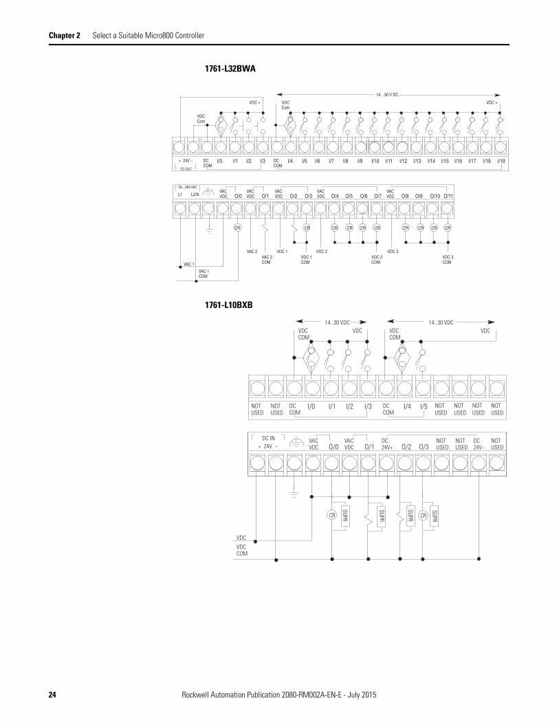
MicroLogix 1000 Controller Wiring
1761-L10BWB
1761-L16BWB
DCCOM
DCCOM
I/0 I/1 I/2 I/3 I/4 I/5 NOTUSED
NOTUSED
NOTUSED
VDC +VDC
14...30VDC
VDCCOM COM
VDC (+)
NOTUSED
NOTUSED
NOTUSEDO/0 O/1 O/2 O/3
VACVDC
VAC
VDC 1 VAC 1 VDC 2 VDC 3
VDC 1COM
VAC 1COM
VDC 2COM
VDC 3COM
VDCVACVDC
VACVDC
DC IN+ 24V -
CR CR
NOTUSED
NOTUSED
NOTUSED
14...30VDC
DCCOM
DCCOM
I/0 I/1 I/2 I/3 I/4 I/5
VDC +VDC14...30VDC
VDCCOM COM
VDC (+)
O/0 O/1 O/2 O/3VACVDC
VAC
VDC 1 VAC 1 VDC 2 VDC 3
VDC 1COM
VAC 1COM
VDC 2COM
VDC 3COM
VDCVACVDC
VACVDC
DC IN+ 24V -
CR CR
NOTUSED
NOTUSED
14...30VDC
I/6 I/7 I/8 I/9
O/4VACVDC O/5
VDC 4
CR CR
VDC 4COM
Rockwell Automation Publication 2080-RM002A-EN-E - July 2015 19

Chapter 2 Select a Suitable Micro800 Controller
1761-L16NWA and 1761-L16NWB
The 1761-L16NWA and 1761-L16NWB controllers are equipped with input circuits capable of 24V AC or 24V DC operation. Specifications for operation of the input circuits are given in the table below. With the exception of the input circuits, the 1761-L16NWA and1761-L16NWB controllers are identical in operation to the 1761-L16BWA and 1761-L16BWB, respectively.
For more information, refer to publication 1761-DU001.
24V AC / 24V DC Input Specifications for 1761-L16NWA and 1761-L16NWB
Specification(1)
(1) Input circuits may be operated AC or DC on a group basis only.
AC Excitation(2)
(2) All AC specifications are sinusoidal RMS values.
DC Excitation
On State Voltage Minimum 18V AC 14V DC
Nominal 24V AC 24V DC
Maximum 26.4V AC @ 55°C (131°F)30V AC @ 30°C (86°F)
26.4V DC @ 55°C (131°F)30V DC @ 30°C (86°F)
On State Current Minimum 3.0 mA @ 18V AC 2.5 mA @ 14V DC
Nominal 8.0 mA @ 24V AC 8.0 mA @ 24V DC
Maximum 12 mA @ 30V AC 12 mA @ 30V DC
Off State Voltage Minimum 0.0V AC 0.0V DC
Maximum 3.0V AC 5.0V DC
Off State Current Minimum 1.0 mA 1.5 mA
Frequency Nominal 50/60 Hzsee Turn On Time/Turn Off Time
Range 47 to 63 Hz
Turn On Time(3)
(3) Turn On and Turn Off Times are not adjustable.
Minimum 2 ms 2 ms
Maximum 20 ms 20 ms
Turn Off Time(3) Minimum 10 ms 10 ms
Maximum 20 ms 20 ms
20 Rockwell Automation Publication 2080-RM002A-EN-E - July 2015

Select a Suitable Micro800 Controller Chapter 2
1761-L32BWB
1761-L10BWA
NOTUSED
NOTUSED
I/9 I/10DCCOM
I/0 I/1 I/2 I/3 I/4 I/5 I/6 I/7 I/8 I/11 I/12 I/13 I/14 I/15 I/16 I/17 I/18DCCOM
I/19
VDC (+) for Sinking14…30 VDC
VDC (–) for SourcingVDC (+) for Sourcing
14…30 VDCVDC (–) for Sinking
NOTUSED
NOTUSED
I/9 I/10DCCOM
I/0 I/1 I/2 I/3 I/4 I/5 I/6 I/7 I/8 I/11 I/12 I/13 I/14 I/15 I/16 I/17 I/18DCCOM
I/19
VDC (–) for Sourcing
14…30 VDC 14…30 VDC
VDC (+) for SinkingVDC (–) for SinkingVDC (+) for Sourcing
Sinking Inputs Sourcing Inputs
Sinking InputsSourcing Inputs
DCCOM
DCCOM
I/0 I/1 I/2 I/3 I/4 I/5 NOTUSED
NOTUSED
NOTUSED
VDC +
DC OUT
+ 24V -
VDC
14...30VDC
VDCCOM
COMVDC (+)
NOTUSED
NOTUSED
NOTUSEDO/0 O/1 O/2 O/3L1 L2/N
VACVDC
VAC
VAC 1 VAC 2 VDC 1 VDC 2 VDC 3
VAC 1COM
VAC 2COM
VDC 1COM
VDC 2COM
VDC 3COM
VDCVACVDC
VACVDC
85...264 VAC
CR CR CR CR
Rockwell Automation Publication 2080-RM002A-EN-E - July 2015 21

Chapter 2 Select a Suitable Micro800 Controller
1761-L16BWA
1761-L16AWA
DCCOM
DCCOM
I/0 I/1 I/2 I/3 I/4 I/5 I/6 I/7 I/8 I/9
VDC +
DC OUT
+ 24V -
VDC
VDCCOM
COMVDC +
O/0 O/1 O/2 O/3L1 L2/NVACVDC
VAC
VAC 1 VAC 2 VDC 1 VDC 2 VDC 3
VAC 1COM
VAC 2COM
VDC 1COM
VDC 2COM
VDC 3COM
VDCVACVDC
VACVDC
85...264 VAC
CR CR CR CR
14...30V DC
O/5O/4VACVDC
NOTUSED
NOTUSED
79...132V AC
L2/N
L1VACVDC O/0
VACVDC O/1
VACVDC O/2 O/3
VACVDC O/4L2/N O/5
85...264 VAC
CR CR
I/9I/0 I/1 I/2 I/3 I/4 I/5 I/6 I/7 I/8ACCOM
ACCOM
L1
CR
1LN/2L
VAC 1VAC 1COM
VAC 2VAC 2COM
VDC 1VDC 1COM
VDC 2VDC 3COM
79...132V AC
VACVDC
CR
VDC 2COM
VDC 3
22 Rockwell Automation Publication 2080-RM002A-EN-E - July 2015

Select a Suitable Micro800 Controller Chapter 2
1761-L32AAA
1761-L32AWA
NOTUSED
NOTUSED
79…132V ACL2/N
VACVDC O/0
VACVDC O/1 VAC O/2 O/3 VAC O/4 O/5 O/6 VAC O/8O/7 O/9 O/10 O/11
I/9 I/10ACCOM
I/0 I/1 I/2 I/3 I/4 I/5 I/6 I/7 I/8 I/11 I/12 I/13 I/14 I/15 I/16 I/17 I/18ACCOM
I/19
L1 L2/N L1
CR CR CRCR CR
VAC 1VAC 1COM
VAC 2VAC 2COM
VAC 3VAC 3COM
CR CRCR CR
VAC 4VAC 4COM
CR
79…132V AC
L1 L2/N
85…264 VAC
VAC 0
VAC 0COM
NOTUSED
NOTUSED
79…132V AC
L2/N
VACVDC O/0
VACVDC O/1
VACVDC O/2 O/3
VACVDC O/4 O/5 O/6
VACVDC O/8O/7 O/9 O/10 O/11
I/9 I/10ACCOM
I/0 I/1 I/2 I/3 I/4 I/5 I/6 I/7 I/8 I/11 I/12 I/13 I/14 I/15 I/16 I/17 I/18ACCOM
I/19
L1 L2/N L1
CR CR CRCR CR
VAC 2VAC 2COM
VDC 1VDC 1COM
VDC 2VDC 2COM
CR CRCR CR
VDC 3VDC 3COM
CR
79…132V AC
L1 L2/N
85…264 VAC
VAC 1
VAC 1COM
Rockwell Automation Publication 2080-RM002A-EN-E - July 2015 23
Chapter 2 Select a Suitable Micro800 Controller
1761-L32BWA
1761-L10BXB
I/9 I/10DCCOM
VDC +
I/0 I/1 I/2 I/3 I/4 I/5 I/6 I/7 I/8 I/11 I/12 I/13 I/14 I/15 I/16 I/17 I/18 I/19DCCOM
VDCCom
VDCCom
VDC +
14…30 V DC
DC OUT
+ 24V –
VACVDC O/0
VACVDC O/1
VACVDC O/2 O/3
VACVDC O/4 O/5 O/6
VACVDC O/8O/7 O/9 O/10 O/11
CR CR CRCR CR
VAC 2VAC 2COM
VDC 1VDC 1COM
VDC 2VDC 2COM
CR CRCR CR
VDC 3VDC 3COM
CR
L1 L2/N
85…264 VAC
VAC 1
VAC 1COM
NOTUSED
NOTUSED
VACVDC O/0
VACVDC O/1
DC24V+ O/2 O/3
I/0 I/1 I/2 I/3 I/4 I/5 NOTUSED
NOTUSED
NOTUSED
NOTUSED
DCCOM
DCCOM
DC24V–
NOTUSED
NOTUSED
NOTUSED
VDC COM
VDC14...30 VDC
VDC COM
VDC14...30 VDC
DC IN+ 24V –
VDC
VDC COM
SUPR
SUPR
SUPRCR
SUPRCR
24 Rockwell Automation Publication 2080-RM002A-EN-E - July 2015

Select a Suitable Micro800 Controller Chapter 2
1761-L16BBB
1761-L20BWA-5A
DCCOM
DCCOM
I/0 I/1 I/2 I/3 I/4 I/5
VDC +VDC14...30VDC
VDCCOM COM
VDC (+)
O/0 O/1 VACVDC
VAC
VDC 1VAC 1 VAC 2 VDC 2
VDC 1COM
VAC 1COM
VAC 2COM
VDC 2COM
VDCDC24V -
DC24V+
DC IN+ 24V -
CR
NOTUSED
NOTUSED
14...30VDC
I/6 I/7 I/8 I/9
O/4 O/5O/3NOTUSEDO/2
I/9 I/10DCCOM
I/0 I/1 I/2 I/3 I/4 I/5 I/6 I/7 I/8 I/11DCCOM
DC OUT
+ 24V –
VDC (–)
VDC (+)VDC (–)
VACVDC O/0
VACVDC O/1
VACVDC O/2 O/3
VACVDC O/4 O/5 O/6
NOTUSEDO/7
CR CR CRCR CR
VAC 2VAC 2COM
VDC 1VDC 1COM
VDC 2VDC 2COM
CR
L1 L2/N
85…264 VAC
VAC 1
VAC 1COM
VDC (+)
IA(–)
IA/3I (+)
IA/2I (+)
IA(–)
IA/1V (+)
IASHD
IA/0V (+)
IASHD
OA(–)
OA/0I (+)
OA/0V (+)
OASHD
14…30V DC AnalogChannels
AnalogChannel
Rockwell Automation Publication 2080-RM002A-EN-E - July 2015 25

Chapter 2 Select a Suitable Micro800 Controller
1761-L20AWA-5A
1761-L20BWB-5A
NOTUSED
NOTUSED
79…132V ACL2/N
VACVDC O/0
VACVDC O/1
VACVDC O/2 O/3
VACVDC O/4 O/5 O/6
NOTUSEDO/7
I/9 I/10ACCOM
I/0 I/1 I/2 I/3 I/4 I/5 I/6 I/7 I/8 I/11ACCOM
1LN/2L1L
CR CR CRCR CR
VAC 2VAC 2COM
VDC 1VDC 1COM
VDC 2VDC 2COM
CR
L1 L2/N
85…264 VAC
VAC 1
VAC 1COM
IA(–)
IA/3I (+)
IA/2I (+)
IASHD
IA/1V (+)
IA/0V (+)
IA(–)
IASHD
OA(–)
OA/0I (+)
OA/0V (+)
OASHD
79…132V ACAnalogChannels
AnalogChannel
NOTUSED
NOTUSED
79...132V ACL2/N
VACVDC O/0
VACVDC O/1
VACVDC O/2 O/3
VACVDC O/4 O/5 O/6
NOTUSEDO/7
I/9 I/10ACCOM
I/0 I/1 I/2 I/3 I/4 I/5 I/6 I/7 I/8 I/11ACCOM
L1 L2/N L1
CR CR CRCR CR
VAC 2VAC 2COM
VDC 1VDC 1COM
VDC 2VDC 2COM
CR
L1 L2/N
85...264 VAC
VAC 1
VAC 1COM
IA(–)
IA/3I (+)
IA/2I (+)
IASHD
IA/1V (+)
IA/0V (+)
IA(–)
IASHD
OA(–)
OA/0I (+)
OA/0V (+)
OASHD
79...132V AC Analogchannels
Analogchannel
26 Rockwell Automation Publication 2080-RM002A-EN-E - July 2015

Select a Suitable Micro800 Controller Chapter 2
1761-L32BBB
NOTUSED
NOTUSED
VACVDC O/0
VACVDC O/1
DC24V+ O/2 O/3 O/4 O/5 O/6
DC24V–O/8O/7 O/9 O/10 O/11
I/9 I/10DCCOM
I/0 I/1 I/2 I/3 I/4 I/5 I/6 I/7 I/8 I/11 I/12 I/13 I/14 I/15 I/16 I/17 I/18DCCOM
I/19
NOTUSED
VDCCom
VDC +14…30V DC
VDC + VDCCom
14…30V DC
CR
VAC 1VAC 1COM
VAC 2VAC 2COM
VDC 2VDC 2COMVDC 1
VDC 1COM
DC IN+ 24V –
Sourcing ConfigurationSinking Configuration
Sourcing Outputs
Rockwell Automation Publication 2080-RM002A-EN-E - July 2015 27

Chapter 2 Select a Suitable Micro800 Controller
Micro820 Controller Wiring
2080-LC20-20QWB, 2080-LC20-20QWBR
-DC24
+DC10 I-00
I-01
I-02
I-03
COM0
I-04
I-05
I-08
I-07
1 2 3 4 5 6 7 8 9 10 11 12
+DC24 -DC24
VO-0-DC24
NU
CM0
O-00
CM1 CM2
O-01
O-03
O-02
1 2 3 4 5 6 7 8 9 10 11 12
I-10
I-09
NU
I-11
13 14 15 16
O-04
CM3
O-06
O-05
13 14 15 16
I-06
-DC b
-DC a
+DC a +DC b
+DC c
-DC c L1 a +DC d +DC e-DC d-DC eL2 a
CR CR CR CR
-DC24
+DC10 I-00
I-01
I-02
I-03
COM0
I-04
I-05
I-08
I-07
1 2 3 4 5 6 7 8 9 10 11 12
+DC24 -DC24
VO-0-DC24
NU
CM0
O-00
CM1 CM2
O-01
O-03
O-02
1 2 3 4 5 6 7 8 9 10 11 12
I-10
I-09
NU
I-11
13 14 15 16
O-04
CM3
O-06
O-05
13 14 15 16
I-06
+DC b
-DC a
+DC a -DC b
+DC c
-DC c L1 a +DC d +DC e-DC d-DC eL2 a
CR CR CR CR
DC Sinking Input Configuration Inputs - Inputs 00...11
DC Sourcing Input Configuration Inputs - Inputs 4…11 only
28 Rockwell Automation Publication 2080-RM002A-EN-E - July 2015

Select a Suitable Micro800 Controller Chapter 2
Micro830 Controller Wiring
2080-LC30-10QWB
2080-LC30-16QWB
High speed inputs and outputs are indicated by
DC Sinking Input Configuration Inputs - Inputs 00...05
.
COM0
COM1
I-01
I-02
I-03 I-04
I-05
1 2 3 4 5 6 7 8 9 10 11 12
+DC24 CM0
O-00-DC24
CM1 CM2
O-01
I-00
O-03O-02
1 2 3 4 5 6 7 8 9 10 11 12
CM3
+DC a +DC b -DC a -DC b
+DC c
-DC c L1 a
L2 a
L1 b
L2 b -DC d
CR
+DC d
CR
NC
NC
NC
NC
NC
NC
COM0
COM1
I-01
I-02
I-03 I-04
I-05 I-07 I-09
I-08I-06
O-04
O-05
1 2 3 4 5 6 7 8 9 10 11 12
+DC24 CM0
O-00-DC24
CM1 CM2
O-01
I-00
O-03O-02
1 2 3 4 5 6 7 8 9 10 11 12
CM3
+DC a +DC b -DC a -DC b
+DC c
-DC c L1 a
L2 a
L1 b
L2 b
CR
+DC d
-DC d
CRCRCR
High speed inputs and outputs are indicated by
DC Sinking Input Configuration Inputs - Inputs 00...09
Rockwell Automation Publication 2080-RM002A-EN-E - July 2015 29

Chapter 2 Select a Suitable Micro800 Controller
2080-LC30-24QWB
2080-LC30-48QWB
COM0
COM1
I-01
I-02
I-03 I-04
I-05 I-07 I-09
I-08I-06
O-04 O-06 O-08
CM3
I-11
I-10
I-13
I-12
1 2 3 4 5 6 7 8 9 10 11 12 13 14 15 16
+DC24 CM0
O-00-DC24
CM1 CM2
O-01
I-00
O-03 O-07 O-09O-02
1 2 3 4 5 6 7 8 9 10 11 12 13 14 15 16
CM3
+DC a +DC b -DC a -DC b
+DC c
-DC c L1 a
L2 a
L1 b
L2 b
CR
-DC d
+DC d
CRCRCRCR
High speed inputs and outputs are indicated by
DC Sinking Inputs - Inputs 00...13
.
COM0
I-04
I-01
I-02
I-03 I-05
COM1 I-07 I-09
I-08I-06
CM4 CM5 CM6
O-04
I-11
I-10
I-12
COM2
1 2 3 4 5 6 7 8 9 10 11 12 13 14 15 16
CM0+DC24
O-00-DC24
CM1 CM2
O-01
I-00
O-03 O-05 O-06O-02
1 2 3 4 5 6 7 8 9 10 11 12 13 14 15 16
CM3
+DC a +DC b -DC a -DC b
+DC e
-DC e
-DC h
+DC h+DC g+DC fL1 cL1 bL1 a
L2 a L2 b L2 c -DC f -DC g
I-13
I-18
I-15
I-16
I-17 I-19
COM3 I-21 I-23
I-22I-20
O-15 O-16 O-18
CM9
I-25
I-24
I-27
I-26
1 2 3 4 5 6 7 8 9 10 11 12 13 14 15 16
CM7 O-08
O-09O-07
O-10 CM8
O-11
I-14
O-14 O-17 O-19O-12
1 2 3 4 5 6 7 8 9 10 11 12 13 14 15 16
O-13
+DC c +DC d -DC c -DC d
-DC k
+DC j
-DC j
+DC k
-DC i+DC i
CR CR CR CR CR CR CR CR CR CR CR CR
DC Sinking Inputs - Inputs 00...27
30 Rockwell Automation Publication 2080-RM002A-EN-E - July 2015

Select a Suitable Micro800 Controller Chapter 2
2080-LC30-16AWB
2080-LC30-48AWB
COM0
COM1
I-01
I-02
I-03 I-04
I-05
I-08
I-07
1 2 3 4 5 6 7 8 9 10 11 12
+DC24 CM0
O-00-DC24
CM1 CM2
O-01
I-00
O-03O-02
1 2 3 4 5 6 7 8 9 10 11 12
I-09
O-04CM3
O-05
I-06
L1 a L2 a L2 b L1 b
+DC a
-DC a L1 c
L2 c
L1 d
L2 d -DC b
CR
+DC b
CRCRCR
2080-LC30-16AWB has no high speed inputs.
COM0
I-04
I-01
I-02
I-03 I-05
COM1 I-07 I-09
I-08I-06
CM4 CM5 CM6
O-04
I-11
I-10
I-12
COM2
1 2 3 4 5 6 7 8 9 10 11 12 13 14 15 16
CM0+DC24
O-00-DC24
CM1 CM2
O-01
I-00
O-03 O-05 O-06O-02
1 2 3 4 5 6 7 8 9 10 11 12 13 14 15 16
CM3
L1 a L1 b L2 a L2 b
+DC a
-DC a
-DC e
+DC e+DC d+DC c+DC bL1 fL1 e
L2 e L2 f -DC b -DC c -DC d
I-13
I-18
I-15
I-16
I-17 I-19
COM3 I-21 I-23
I-22I-20
O-15 O-16 O-18
CM9
I-25
I-24
I-27
I-26
1 2 3 4 5 6 7 8 9 10 11 12 13 14 15 16
CM7 O-08
O-09O-07
O-10 CM8
O-11
I-14
O-14 O-17 O-19O-12
1 2 3 4 5 6 7 8 9 10 11 12 13 14 15 16
O-13
L1 c L1 d L2 c L2 d
L2 g
+DC g
-DC g
L1 g
-DC f+DC f
CR CRCR CR CR CR CR CR CR CR
2080-LC30-48AWB has no high speed inputs.
Rockwell Automation Publication 2080-RM002A-EN-E - July 2015 31

Chapter 2 Select a Suitable Micro800 Controller
2080-LC30-48QBB
COM0
I-04
I-01
I-02
I-03 I-05
COM1 I-07 I-09
I-08I-06
O-05 O-07 O-09
O-06
I-11
I-10
I-12
COM2
1 2 3 4 5 6 7 8 9 10 11 12 13 14 15 16
+CM0+DC24
O-00-DC24
O-01 O-03
O-02
I-00
O-04 O-08 -CM1-CM0
1 2 3 4 5 6 7 8 9 10 11 12 13 14 15 16
+CM1
+DC a +DC b -DC a -DC b
+DC e
-DC e
+DC f+DC g
-DC g
I-13
I-18
I-15
I-16
I-17 I-19
COM3 I-21 I-23
I-22I-20
O-17 O-19 NC
O-18
I-25
I-24
I-27
I-26
1 2 3 4 5 6 7 8 9 10 11 12 13 14 15 16
+CM2 O-11
O-12O-10
O-13 O-15
O-14
I-14
O-16 -CM3 NC-CM2
1 2 3 4 5 6 7 8 9 10 11 12 13 14 15 16
+CM3
+DC c +DC d -DC c -DC d
-DC i+DC i
-DC h+DC h-DC f
DC Sinking Inputs - Inputs 00...27
High speed inputs and outputs are indicated by .
32 Rockwell Automation Publication 2080-RM002A-EN-E - July 2015

Chapter 3
Convert an RSLogix 500 Project to a Connected Components Workbench Project
Overview
This chapter illustrates two ways that you can convert an existing RSLogix 500 project to a Connected Components Workbench project for your Micro800 controller: manually, and using the MicroLogix 1000 to Micro800 Converter Tool.
For reference, we use an RSLogix 500 Pick and Place Machine application as an example and convert it to a Connected Components Workbench project for a Micro830 controller (Catalog Number 2080-LC30-16QWB). Not all steps may be applicable for your project. You can use the instructions as a guide and make changes depending on the type of your controller and on the application you are converting.
Refer to Chapter 4 for information about the functional difference between the Relay Ladder Logic instructions of the RSLogix 500 software and the Connected Components Workbench software.
For more information about using the Connected Components Workbench software, refer to the following:• Micro800 and Connected Components Workbench Getting Started Guide, publication 2080-QR001 • Micro800 and Connected Components Workbench Application Guide, publication 2080-QR002 • Connected Components Workbench Help
The general steps for manual conversion can be summarized as follows:• Generate an Existing RSLogix 500 Project Report• Create Equivalent Program Files in Connected Components Workbench• Create Representative Data Files in Connected Components Workbench• Create an Equivalent Program in Connected Components Workbench• Build and Test the Connected Components Workbench Project
The general steps for conversion using the MicroLogix 1000 to Micro800 Converter Tool can be summarized as follows:• Download and Install the MicroLogix to Micro800 Converter Tool• Save the RSLogix 500 Project as an SLC File• Run the MicroLogix to Micro800 Converter Tool• Convert the SLC File to a Connected Components Workbench Project
Rockwell Automation Publication 2080-RM002A-EN-E - July 2015 33

Chapter 3 Convert an RSLogix 500 Project to a Connected Components Workbench Project
Before You Begin Ensure that you have properly installed the Connected Components Workbench software, revision 8 or later.
What You Need The following are needed for this procedure:• Connected Components Workbench revision 8 or later• Firmware revision 8 or later
Generate an Existing RSLogix 500 Project Report
The RSLogix 500 report for your application contains information such as a program file list, a data file list, and ladder diagrams. This information is used as reference when creating a program in Connected Components Workbench.
1. Open the existing RSLogix 500 project.
2. Go to File → Report Options.
3. Modify the report options as necessary.
4. Click the Print button.
34 Rockwell Automation Publication 2080-RM002A-EN-E - July 2015

Convert an RSLogix 500 Project to a Connected Components Workbench Project Chapter 3
Create Equivalent Program Files in Connected Components Workbench
Create the equivalent program files in Connected Components Workbench for your RSLogix 500 project.
1. Open the Connected Components Workbench software.
2. On the Device Toolbox, select a Micro800 controller, and then double-click it or drag it to the Project Organizer panel.
Click the + symbol to expand the folders and locate a specific Micro800 controller.
For this example, use a Micro830 controller (Catalog Number 2080-LC30-16QWB).
You are then asked to select the Micro800 revision to add to the project.
3. For this example, select 8 from the Major revision drop-down, and then click the OK button.
Rockwell Automation Publication 2080-RM002A-EN-E - July 2015 35

Chapter 3 Convert an RSLogix 500 Project to a Connected Components Workbench Project
The selected Micro830 controller displays in the Project Organizer panel.
4. On the Project Organizer, right-click Programs, and then select Add → New LD: Ladder Diagram.
5. Repeat the previous step until you have added the same number of program files present in the RSLogix 500 application.
6. Rename the added ladder diagrams following the names of the program files in the RSLogix 500 application.
36 Rockwell Automation Publication 2080-RM002A-EN-E - July 2015

Convert an RSLogix 500 Project to a Connected Components Workbench Project Chapter 3
To rename, right-click on a program and then select Rename.
This section shows how you can replicate the equivalent program files for the RSLogix 500 project in Connected Components Workbench. However, only the Ladder 2 program (MAIN_PROG) is needed for the rest of this guide.
Note that users have to determine which ladder files have programed rungs in them.
In this example, Ladder files 3 to 5 are interrupt files. If any of the ladder files have ladder logic in them, the ladder logic needs to be converted. Specific interrupts must also be configured in Connected Components Workbench and the program file must be assigned to that interrupt. Refer to Configure Interrupts on a Micro800 Controller (Example) on page 38 for more information.
Ladder files 6-15 are subroutine files which, if there is logic in them, must be called from ladder file 2 using a JSR instruction (not supported in Connected Components Workbench). You can incorporate the ladder logic from the subroutine file into the MAIN_PROG program or create a UDFB program that performs the function of the subroutine file and call the UDFB program from within the MAIN_PROG program.
7. Go to File → Save Project As.
TIP You can change the order of program execution by dragging and dropping each program on the Project Organizer panel accordingly.
Rockwell Automation Publication 2080-RM002A-EN-E - July 2015 37

Chapter 3 Convert an RSLogix 500 Project to a Connected Components Workbench Project
Enter the name and location for this project, and then click the OK button.
Configure Interrupts on a Micro800 Controller (Example)
For this example, use a Selectable Timed Interrupt.
1. Create a program to execute when the interrupt occurs.a. On the Project Organizer panel, right-click Programs, and then select
Add → New LD: Ladder Diagram.b. Rename the program as STI_INT.
2. On the Project Organizer panel, double-click Micro830. The Micro830 Controller tab displays.
38 Rockwell Automation Publication 2080-RM002A-EN-E - July 2015

Convert an RSLogix 500 Project to a Connected Components Workbench Project Chapter 3
3. On the lower left of the tab, expand Controller, and then click Interrupts.
4. On the Controller - Interrupts section (right), click Add.The Add Selectable Time Interrupt (STI) window displays.
5. Set the STI properties and parameters:a. Interrupt Type [Selectable Timed Interrupt (STI)]b. STI ID (STI0)c. Program (the program created earlier)d. Auto Start (selected)e. Set Point (10 ms)
Rockwell Automation Publication 2080-RM002A-EN-E - July 2015 39

Chapter 3 Convert an RSLogix 500 Project to a Connected Components Workbench Project
6. Click the Apply button, and then click the OK button.The Micro830 Workspace displays.
Create Representative Data Files in Connected Components Workbench
Using the report generated as reference, create representative data files in Connected Components Workbench by setting up the variables for the project.
In this pick and place application example, the following data files are used:• Output (O0)• Input (I1)• Binary (B3)• Integer (N7)
Set Up Embedded I/O Variables
1. On the Project Organizer panel, double-click Global Variables.
2. Create an alias for the embedded I/O following the comments in RSLogix 500.
Follow this Connected Components Workbench I/O addressing:
OUTPUT (O0) = _IO_EM_DO_XX (For example, O:0/0 = _IO_EM_DO_00)
TIP The configured Interrupt(s) can be configured or deleted from the Controller- Interrupts Workspace.
40 Rockwell Automation Publication 2080-RM002A-EN-E - July 2015
Convert an RSLogix 500 Project to a Connected Components Workbench Project Chapter 3
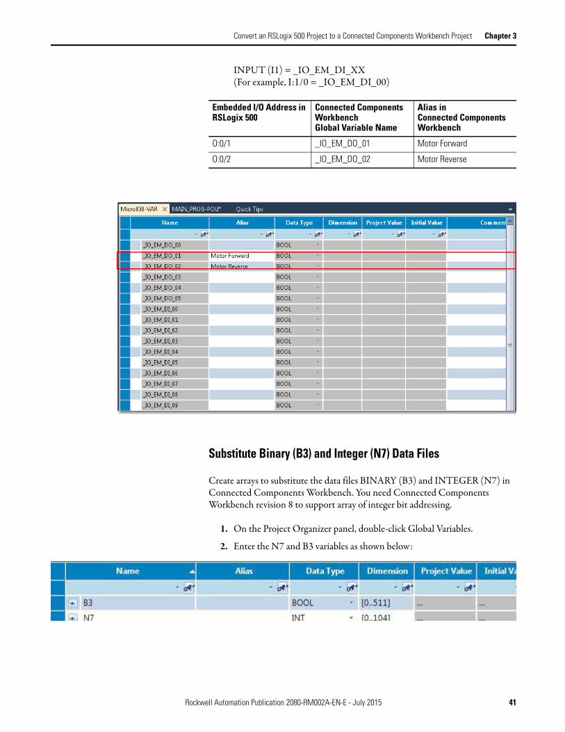
INPUT (I1) = _IO_EM_DI_XX (For example, I:1/0 = _IO_EM_DI_00)
Substitute Binary (B3) and Integer (N7) Data Files
Create arrays to substitute the data files BINARY (B3) and INTEGER (N7) in Connected Components Workbench. You need Connected Components Workbench revision 8 to support array of integer bit addressing.
1. On the Project Organizer panel, double-click Global Variables.
2. Enter the N7 and B3 variables as shown below:
Embedded I/O Address in RSLogix 500
Connected Components Workbench Global Variable Name
Alias in Connected Components Workbench
O:0/1 _IO_EM_DO_01 Motor Forward
O:0/2 _IO_EM_DO_02 Motor Reverse
Rockwell Automation Publication 2080-RM002A-EN-E - July 2015 41

Chapter 3 Convert an RSLogix 500 Project to a Connected Components Workbench Project
Set Up Variables for Index Addressing
In this pick and place application example, Index Addressing is used to store the encoder counts of the bin locations (total 8 bins).
The section shows the steps for setting up the variables needed for programming Index Addressing in Connected Components Workbench. Programming steps are shown in Program Index Addressing on page 52.
1. On the Project Organizer panel, under MAIN_PROG, double-click Local Variables.
2. Add the following variables:
• Offset_Value is the equivalent of the Index Register (S:24 in RSLogix 500)
• The sum of the Offset_Value and Base_Address is the Offset_Address.• The data stored at N7[Offset_Address] is then passed to N7[2].
Set Up High Speed Counter (HSC) Instruction Variables
The controller uses Indexed Addressing to locate the correct encoder count from the data table N7[10] to N7[17] and load the information into the high preset of the high-speed counter.
The HSC instruction is required to allow the HSC parameters (N7[0] to N7[4]) to be loaded for the same instruction:
Name Data Type
Offset_Value DINT
Base_Address DINT
Offset_Address DINT
Name Data Value Details
N7[0] 0001h Output Mask - Control gripper
N7[1] 0000h Output pattern for High Preset - Turn off gripper
42 Rockwell Automation Publication 2080-RM002A-EN-E - July 2015

Convert an RSLogix 500 Project to a Connected Components Workbench Project Chapter 3
The number of pulses the head needs to travel to reach each bin location is stored in a data table starting at address N7 [10] and ending at N7 [17]. This is entered under the Initial Value field so that it is used as the value of a variable when a controller starts execution for the first time, such as after a program download.
1. On the Project Organizer panel, double-click Global Variables.
2. Click the + symbol for the variable N7 to expand the row.
3. Double-click the Initial Value field for N7 [0], and then enter “01”.
4. Repeat step 3 for N7 [1] to N7[4] and N7[10] to N7[17] for the rest of the data values as shown on the tables above.
The image below shows the completed entries:
N7[2] 100d High Preset - loaded from table N7[10] to N7[17].
N7[3] 0001h Output pattern for Low Preset - Turn on gripper
N7[4] 0d Low Preset - home position when encoder triggers Z-reset.
Name Data Value Details
N7[10] 100d Number of pulses to reach Bin Location A
N7[11] 200d Number of pulses to reach Bin Location B
N7[12] 300d Number of pulses to reach Bin Location C
N7[13] 400d Number of pulses to reach Bin Location D
N7[14] 500d Number of pulses to reach Bin Location E
N7[15] 600d Number of pulses to reach Bin Location F
N7[16] 700d Number of pulses to reach Bin Location G
N7[17] 800d Number of pulses to reach Bin Location H
Name Data Value Details
Rockwell Automation Publication 2080-RM002A-EN-E - July 2015 43

Chapter 3 Convert an RSLogix 500 Project to a Connected Components Workbench Project
Create an Equivalent Program in Connected Components Workbench
The following are instructions used in MicroLogix 1000 for this pick and place application example:
• XIC, XIO, OTE, RES, OUT, OTL, and TON• GRT and NEQ• MOV• HSC and HSL
The RES and HSL instructions are not supported by Connected Components Workbench.
In this application, Index Addressing is used to store the encoder counts of the bin locations (total 8 bins).
This section walks you through on how to work with the Index Addressing, as well as High Speed Counter and Timer On-Delay instruction sets in Connected Components Workbench.
Basic Ladder Programming Tasks
Refer to the following instructions to familiarize yourself with the basic tasks for creating ladder diagrams in Connected Components Workbench before proceeding with the succeeding sections.
• Add a Rung on page 45• Add Ladder Diagram Elements on page 46• Add an Instruction Block on page 47• Modify Instruction Parameters on page 49• Add Comments on page 50
44 Rockwell Automation Publication 2080-RM002A-EN-E - July 2015

Convert an RSLogix 500 Project to a Connected Components Workbench Project Chapter 3
Add a Rung
1. On the Project Organizer panel, double-click the program for which you want to modify the ladder diagram. (For example, MAIN_PROG)
2. On the Toolbox panel, double-click Rung.
An empty rung displays.
Rockwell Automation Publication 2080-RM002A-EN-E - July 2015 45

Chapter 3 Convert an RSLogix 500 Project to a Connected Components Workbench Project
Add Ladder Diagram Elements
1. On the Toolbox panel, select an element. (For example, Direct Contact)
2. Drag the selected element and place it on top of the rung.
The Variable Selector dialog displays.
3. Select a variable.a. Select the tab where you can locate the a specific variable.
(For example, I/O - Micro830)
46 Rockwell Automation Publication 2080-RM002A-EN-E - July 2015

Convert an RSLogix 500 Project to a Connected Components Workbench Project Chapter 3
b. Click the variable row. (For example, _IO_EM_DI_05)
c. Either click the OK button or double-click the selected variable row.
The variable row displays as follows:
Add an Instruction Block
1. On the Toolbox panel, select Instruction Block.
2. Drag Instruction Block and place it on top of your preferred rung.
Rockwell Automation Publication 2080-RM002A-EN-E - July 2015 47
Chapter 3 Convert an RSLogix 500 Project to a Connected Components Workbench Project
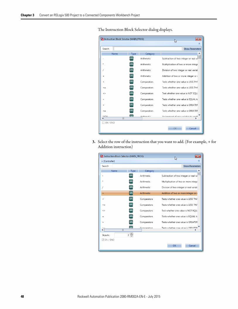
The Instruction Block Selector dialog displays.
3. Select the row of the instruction that you want to add. (For example, + for Addition instruction)
48 Rockwell Automation Publication 2080-RM002A-EN-E - July 2015

Convert an RSLogix 500 Project to a Connected Components Workbench Project Chapter 3
4. Either click the OK button or double-click the selected instruction.The variable row displays as follows:
Modify Instruction Parameters
1. Click on the blank space on top of a parameter. (For example, i1)
2. Type in the parameter or select from the drop-down list. (For example, Offset_Value)
3. Press the Enter key or double-click the selection.The variable row displays as follows:.
Rockwell Automation Publication 2080-RM002A-EN-E - July 2015 49

Chapter 3 Convert an RSLogix 500 Project to a Connected Components Workbench Project
Add Comments
1. Double-click the comments bar on the rung.
2. Enter a comment.
3. (Optional) Change the display properties according to your preference. To do this, click on the rung, and then make changes on the Properties panel.
For this example, change the Comment Background Color to LightGreen.
50 Rockwell Automation Publication 2080-RM002A-EN-E - July 2015

Convert an RSLogix 500 Project to a Connected Components Workbench Project Chapter 3
Replicate the Ladder Diagram
Using the instructions in Basic Ladder Programming Tasks on page 44, replicate the following ladder diagram as shown in the report.
1. Add three rungs with the following elements:
Rung Element Variable
1 Direct Contact _IO_EM_DI_05
Direct Coil Offset_Value.0
2 Direct Contact _IO_EM_DI_06
Direct Coil Offset_Value.1
3 Direct Contact _IO_EM_DI_07
Direct Coil Offset_Value.2
Rockwell Automation Publication 2080-RM002A-EN-E - July 2015 51

Chapter 3 Convert an RSLogix 500 Project to a Connected Components Workbench Project
2. Enter the comments as shown on the report.
Program Index Addressing
In the RSLogix 500 project, Index Register is utilized to select the proper bin location from the table starting at N7:10. In Connected Components Workbench, we replace it with N7[10], which was created earlier.
The ladder program below allows indexed addressing to be used in Connected Components Workbench.
1. Add a new rung.
52 Rockwell Automation Publication 2080-RM002A-EN-E - July 2015

Convert an RSLogix 500 Project to a Connected Components Workbench Project Chapter 3
On the Toolbox panel, double-click Rung. A new rung displays.
2. Add a + (Addition) instruction block to rung 4.
On the Toolbox panel, drag Instruction Block into the blank rung and select MOV from the Instruction Block Selector window.
Enter the following parameters:
i1 = Output_Valuei2 = Base_Addresso1= Offset_Address
Add a branch to the + instruction block. On the Toolbox panel, drag Branch and place it above the + (Addition)
Rockwell Automation Publication 2080-RM002A-EN-E - July 2015 53

Chapter 3 Convert an RSLogix 500 Project to a Connected Components Workbench Project
instruction block.
3. On the Branch, place a MOV instruction block with the following parameters:
54 Rockwell Automation Publication 2080-RM002A-EN-E - July 2015
Convert an RSLogix 500 Project to a Connected Components Workbench Project Chapter 3
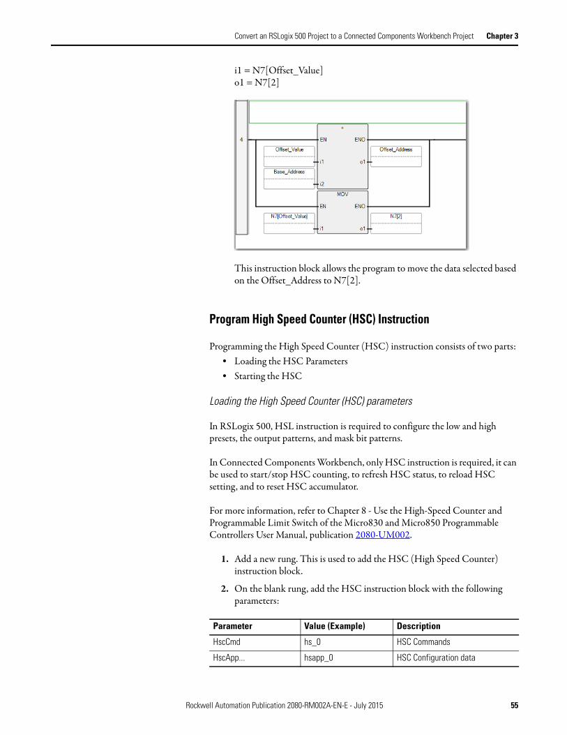
i1 = N7[Offset_Value]o1 = N7[2]
This instruction block allows the program to move the data selected based on the Offset_Address to N7[2].
Program High Speed Counter (HSC) Instruction
Programming the High Speed Counter (HSC) instruction consists of two parts:• Loading the HSC Parameters• Starting the HSC
Loading the High Speed Counter (HSC) parameters
In RSLogix 500, HSL instruction is required to configure the low and high presets, the output patterns, and mask bit patterns.
In Connected Components Workbench, only HSC instruction is required, it can be used to start/stop HSC counting, to refresh HSC status, to reload HSC setting, and to reset HSC accumulator.
For more information, refer to Chapter 8 - Use the High-Speed Counter and Programmable Limit Switch of the Micro830 and Micro850 Programmable Controllers User Manual, publication 2080-UM002.
1. Add a new rung. This is used to add the HSC (High Speed Counter) instruction block.
2. On the blank rung, add the HSC instruction block with the following parameters:
Parameter Value (Example) Description
HscCmd hs_0 HSC Commands
HscApp... hsapp_0 HSC Configuration data
Rockwell Automation Publication 2080-RM002A-EN-E - July 2015 55

Chapter 3 Convert an RSLogix 500 Project to a Connected Components Workbench Project
The rung below shows the HSC instruction created in Connected Components Workbench:
3. Add a new rung. This is used to add the ANY_TO_UDINT and MOV instruction blocks.
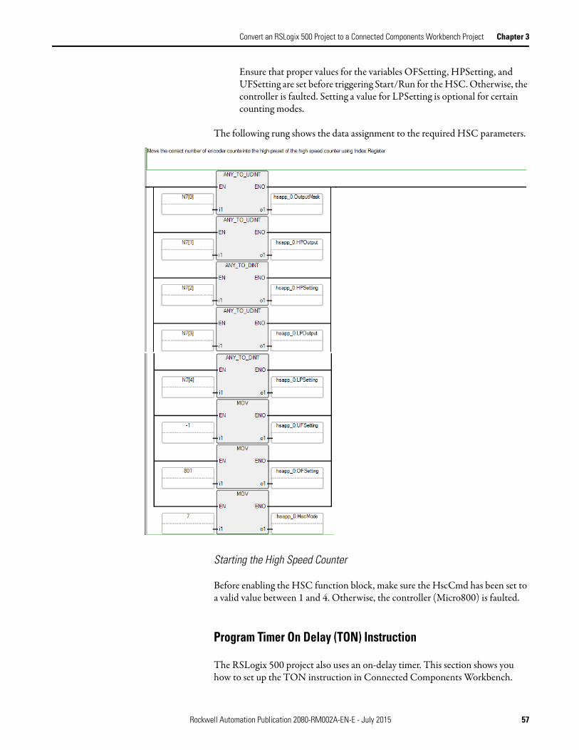
4. On the blank rung, add the HSC and MOV instruction blocks with the following parameters:
HscStsln... hsstats_0 HSC Status information
PlsData hsp_0 Programmable Limit Switch Data
Sts (blank)
Instruction Parameter Values Details
ANY_TO_UDINT i1 N7[0] OutputMask
o1 hsapp_0.OutputMask
ANY_TO_UDINT i1 N7[1] High Preset Output
o1 hsapp_0.HPOutput
ANY_TO_DINT i1 N7[2] High Preset Setting
o1 hsapp_0.HPSetting
ANY_TO_UDINT i1 N7[3] Low Preset Output
o1 hsapp_0.LPOutput
ANY_TO_DINT i1 N7[4] Low Preset Setting
o1 hsapp_0.LPSetting
MOV i1 -1 Underflow setting
o1 hsapp_0.UFSetting
MOV i1 801 Overflow setting
o1 hsapp_0.OFSetting
MOV i1 7 Quadrature Counter with external Reset and Hold
o1 hsapp_0.HscMode
Parameter Value (Example) Description
56 Rockwell Automation Publication 2080-RM002A-EN-E - July 2015
Convert an RSLogix 500 Project to a Connected Components Workbench Project Chapter 3
Ensure that proper values for the variables OFSetting, HPSetting, and UFSetting are set before triggering Start/Run for the HSC. Otherwise, the controller is faulted. Setting a value for LPSetting is optional for certain counting modes.
The following rung shows the data assignment to the required HSC parameters.
Starting the High Speed Counter
Before enabling the HSC function block, make sure the HscCmd has been set to a valid value between 1 and 4. Otherwise, the controller (Micro800) is faulted.
Program Timer On Delay (TON) Instruction
The RSLogix 500 project also uses an on-delay timer. This section shows you how to set up the TON instruction in Connected Components Workbench.
Rockwell Automation Publication 2080-RM002A-EN-E - July 2015 57
Chapter 3 Convert an RSLogix 500 Project to a Connected Components Workbench Project
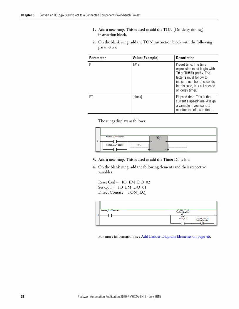
1. Add a new rung. This is used to add the TON (On-delay timing) instruction block.
2. On the blank rung, add the TON instruction block with the following parameters:
The rungs displays as follows:
3. Add a new rung. This is used to add the Timer Done bit.
4. On the blank rung, add the following elements and their respective variables:
Reset Coil = _IO_EM_DO_02Set Coil = _IO_EM_DO_01Direct Contact = TON_1.Q
For more information, see Add Ladder Diagram Elements on page 46.
Parameter Value (Example) Description
PT T#1s Preset time. The time expression must begin with T# or TIME# prefix. The letter s must follow to indicate number of seconds. In this case, it is a 1 second on delay timer.
ET (blank) Elapsed time. This is the current elapsed time. Assign a variable if you want to monitor the elapsed time.
58 Rockwell Automation Publication 2080-RM002A-EN-E - July 2015

Convert an RSLogix 500 Project to a Connected Components Workbench Project Chapter 3
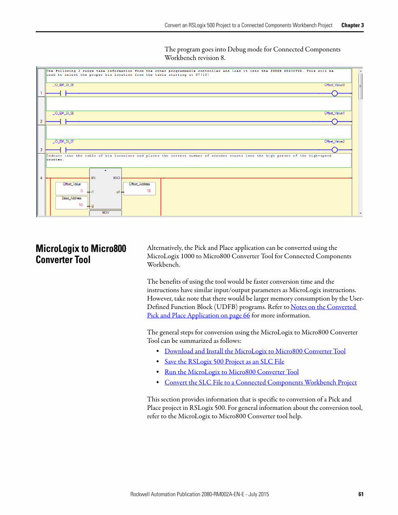
The graphic below shows the converted rung that is using the On-delay timer instruction in Connected Components Workbench:
Refer to Appendix A to view the converted Pick and Place application in Connected Components Workbench.
Build and Test the Connected Components Workbench Project
After you have created the equivalent program, build and test the Connected Components Workbench project.
1. Build the project by selecting Device → Build from the menu bar.
The Output window displays. The build result should show 0 error.
2. Download the project to the controller by selecting Device → Download from the menu bar.
Rockwell Automation Publication 2080-RM002A-EN-E - July 2015 59

Chapter 3 Convert an RSLogix 500 Project to a Connected Components Workbench Project
The Connection Browser window displays.
3. Select the controller, and then click OK.
The Download Confirmation dialog displays.
4. Select Download. This starts downloading the project.
Once downloading is completed, the Download Confirmation dialog displays.
5. Click Yes to put the Controller into RUN mode to test the program.
6. On the Project Organizer panel, double-click on Main_PROG to show the ladder program.
Active rungs are displayed in red and inactive rungs in blue. You can monitor the live values in the program.
60 Rockwell Automation Publication 2080-RM002A-EN-E - July 2015
Convert an RSLogix 500 Project to a Connected Components Workbench Project Chapter 3
The program goes into Debug mode for Connected Components Workbench revision 8.
MicroLogix to Micro800 Converter Tool
Alternatively, the Pick and Place application can be converted using the MicroLogix 1000 to Micro800 Converter Tool for Connected Components Workbench.
The benefits of using the tool would be faster conversion time and the instructions have similar input/output parameters as MicroLogix instructions. However, take note that there would be larger memory consumption by the User-Defined Function Block (UDFB) programs. Refer to Notes on the Converted Pick and Place Application on page 66 for more information.
The general steps for conversion using the MicroLogix to Micro800 Converter Tool can be summarized as follows:
• Download and Install the MicroLogix to Micro800 Converter Tool• Save the RSLogix 500 Project as an SLC File• Run the MicroLogix to Micro800 Converter Tool• Convert the SLC File to a Connected Components Workbench Project
This section provides information that is specific to conversion of a Pick and Place project in RSLogix 500. For general information about the conversion tool, refer to the MicroLogix to Micro800 Converter tool help.
Rockwell Automation Publication 2080-RM002A-EN-E - July 2015 61
Chapter 3 Convert an RSLogix 500 Project to a Connected Components Workbench Project
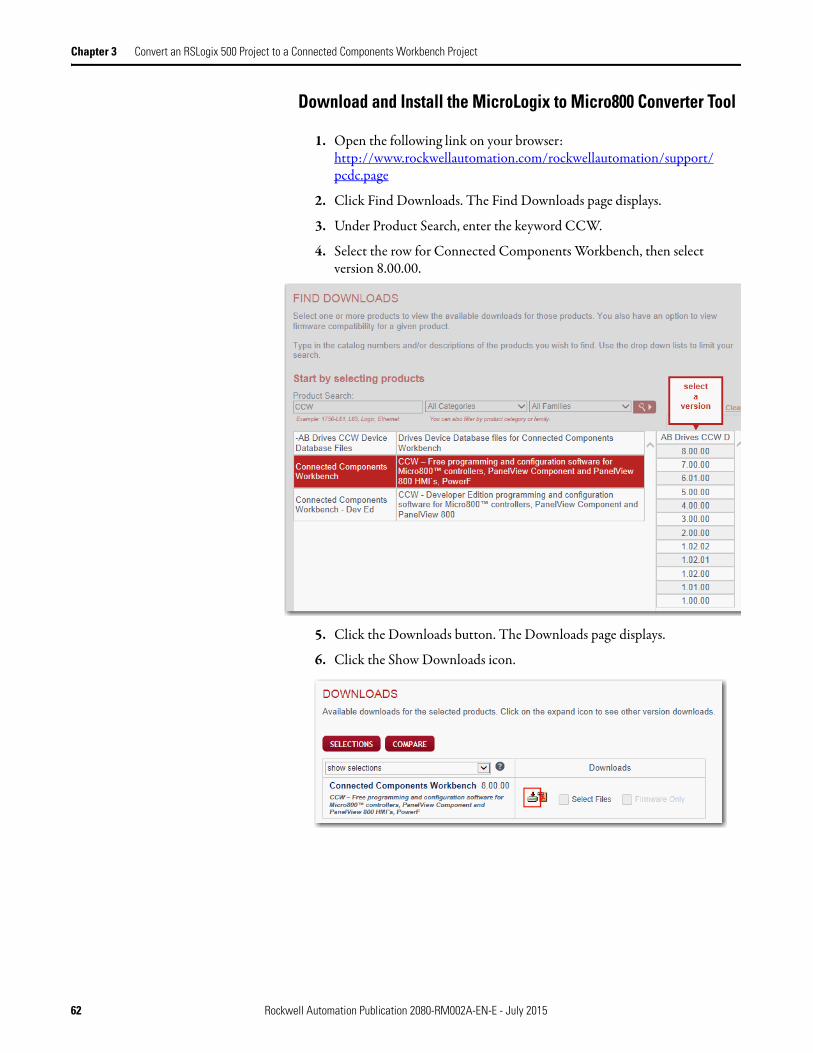
Download and Install the MicroLogix to Micro800 Converter Tool
1. Open the following link on your browser:http://www.rockwellautomation.com/rockwellautomation/support/pcdc.page
2. Click Find Downloads. The Find Downloads page displays.
3. Under Product Search, enter the keyword CCW.
4. Select the row for Connected Components Workbench, then select version 8.00.00.
5. Click the Downloads button. The Downloads page displays.
6. Click the Show Downloads icon.
62 Rockwell Automation Publication 2080-RM002A-EN-E - July 2015

Convert an RSLogix 500 Project to a Connected Components Workbench Project Chapter 3
The Available Downloads dialog box displays.
7. Select the MicroLogix to Micro800 Conversion Tool.If you are not logged-in to Web site, sign in with your login credentials.
8. Download and install the application.
Save the RSLogix 500 Project as an SLC File
1. Using the same Pick and Place project in RSLogix 500 (named as Pick and Place in this example), export the project in SLC™ format. Follow these field settings:• Save as type - Library Files (*.SLC)• Export database - selected• Export file types - Logix
Rockwell Automation Publication 2080-RM002A-EN-E - July 2015 63

Chapter 3 Convert an RSLogix 500 Project to a Connected Components Workbench Project
2. Click the Save button.The Export SLC Format dialog box displays.
3. Click the OK button.The Export Results dialog box displays.
4. Click the OK button to close the dialog box.
64 Rockwell Automation Publication 2080-RM002A-EN-E - July 2015

Convert an RSLogix 500 Project to a Connected Components Workbench Project Chapter 3
Run the MicroLogix to Micro800 Converter Tool
There are two ways to run the MicroLogix to Micro800 Converter tool:• From the Connected Components Workbench menu bar
Select Tools → MicroLogix Library Conversion.
The MicroLogix to Micro800 Conversion dialog displays.
• By command line executionYou can run the converter tool via command line. The command must be executed in the Connected Components Workbench installation directory using this syntax:
CCW.Shell.exe/MicroLogixConv SourceSlcFilePath TargetCatalogID [optionConcatenateComment]
Argument Description
SourceSlcFilePath Provides the path to the .slc file to be converted.
TargetCatalogID Specifies the Catalog ID for the target controller.
optionConcatenateComment
Has a value of either True or False. Determines whether or not the instruction description is shortened to just the comment.
Rockwell Automation Publication 2080-RM002A-EN-E - July 2015 65

Chapter 3 Convert an RSLogix 500 Project to a Connected Components Workbench Project
In the following example, the SLC file named Pick and Place is being converted for use with a Micro830 controller with the catalog number 2080-LC30-16QWB and the instruction descriptions should not be concatenated.
Convert the SLC File to a Connected Components Workbench Project
1. Run the MicroLogix to Micro800 Converter tool.From the Connected Components Workbench menu bar, select Tools → MicroLogix Library Conversion.
2. Under MicroLogix Source, do the following:a. In Source Project (*.SLC), locate the saved Pick and Place project.
Ensure that the documentation files are in the same directory.b. Select the Documentation file(s) using the same name check-box.
3. Under Micro800 Target, from the Catalog ID drop-down, select 2080-LC30-16QWB.
4. Under Option, select the Concatenate instruction... check-box if you want to concatenate the instruction descriptions to variable comment.
5. Click the OK button.
Notes on the Converted Pick and Place Application
The converted SLC file appears similar to the following:
66 Rockwell Automation Publication 2080-RM002A-EN-E - July 2015

Convert an RSLogix 500 Project to a Connected Components Workbench Project Chapter 3
• By default, the Interrupt3_USER_FAULT POU program is created. From the RSLogix 500 project, the MAIN_PROG (Lad 2) program is converted to “MAIN_PROG” in Connected Components Workbench, while USER_FAULT (Lad 3), HSC_INT (Lad 4), STI_INT (Lad 5) and Lad 6 to Lad 16 from the RSLogix 500 project are converted to a User Defined Function Block (UDFB).
• The converter tool adds other Interrupts (for example, Interrupt4_HSC_INT) if any HSC related instructions are present in the project.You can configure it to an interrupt from the controller configuration section or delete the interrupt program if the interrupt is not needed in the program.
• For this project, the Interrupt3_USER_FAULT can be deleted when not in use.
• For Jump to Subroutine ( JSR), the converter tool creates a call to the UDFB (subroutine that is called in JSR) in the program.
• The following data types are converted into an array (under Global Variables).
• The partially supported MicroLogix 1000 instructions are converted into a user defined function block (UDFB) that contains logic to perform the function of the MicroLogix instruction.
Refer to the converter tool help for more information about the fully supported, partially supported, and unsupported MicroLogix 1000 instructions.
• At the end of the conversion process results are displayed in Output and Error List windows, in addition to being stored in the conversion log file.The Error List window provides information about the items in that did not completely convert from your source project to your new project.
Rockwell Automation Publication 2080-RM002A-EN-E - July 2015 67

Chapter 3 Convert an RSLogix 500 Project to a Connected Components Workbench Project
The Output window displays the location of the Conversion Report in CSV format, where you can find all information from the Error list.
Once no errors are encountered and all warnings have been addressed, save the project and test to see if it has the desired behavior.
Refer to Appendix A to view the Pick and Place project in RSLogix 500 and in Connected Components Workbench after using the converter tool.
68 Rockwell Automation Publication 2080-RM002A-EN-E - July 2015

Chapter 4
RLL Instruction Mapping
Overview The purpose of this chapter is to identify the functional difference between the RLL instructions of the RSLogix 500 and Connected Components Workbench software. The RSLogix 500 software is a ladder logic programming package for the SLC™ 500 and MicroLogix processors. On the other hand, Connected Components Workbench is used to develop programs for Micro800 controllers.
The comparison only points out the logic and behavioral differences and does not explain each instruction in detail. Please refer to the reference manual for more details.
Definitions, Acronyms, and Abbreviations
Refer to the following table for definitions of terms used in this chapter.
Term Definition
RLL Relay Ladder Logic
CCW Connected Components Workbench
MSB Most Significant Bit
Rockwell Automation Publication 2080-RM002A-EN-E - July 2015 69
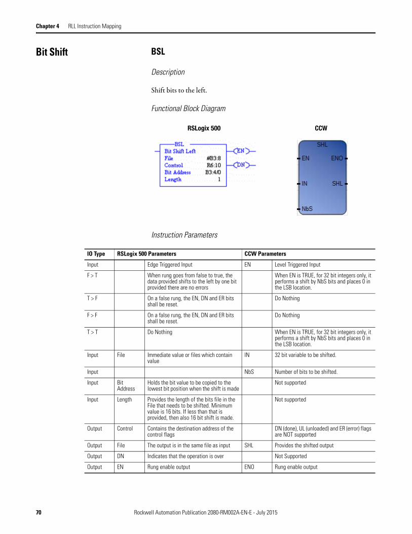
Chapter 4 RLL Instruction Mapping
Bit Shift BSL
Description
Shift bits to the left.
Functional Block Diagram
Instruction Parameters
RSLogix 500 CCW
IO Type RSLogix 500 Parameters CCW Parameters
Input Edge Triggered Input EN Level Triggered Input
F > T When rung goes from false to true, the data provided shifts to the left by one bit provided there are no errors
When EN is TRUE, for 32 bit integers only, it performs a shift by NbS bits and places 0 in the LSB location.
T > F On a false rung, the EN, DN and ER bits shall be reset.
Do Nothing
F > F On a false rung, the EN, DN and ER bits shall be reset.
Do Nothing
T > T Do Nothing When EN is TRUE, for 32 bit integers only, it performs a shift by NbS bits and places 0 in the LSB location.
Input File Immediate value or files which contain value
IN 32 bit variable to be shifted.
Input NbS Number of bits to be shifted.
Input Bit Address
Holds the bit value to be copied to the lowest bit position when the shift is made
Not supported
Input Length Provides the length of the bits file in the File that needs to be shifted. Minimum value is 16 bits. If less than that is provided, then also 16 bit shift is made.
Not supported
Output Control Contains the destination address of the control flags
DN (done), UL (unloaded) and ER (error) flags are NOT supported
Output File The output is in the same file as input SHL Provides the shifted output
Output DN Indicates that the operation is over Not Supported
Output EN Rung enable output ENO Rung enable output
70 Rockwell Automation Publication 2080-RM002A-EN-E - July 2015

RLL Instruction Mapping Chapter 4
CCW Limitations
1. The SHL instruction only provides a 32 bit data right shift.
2. There is NO indication of the last unloaded bit (UL) when a left shift is made.
3. It does not indicate that the operation is over using a DN bit.
4. Does NOT have the provision to insert a bit at the lowest bit position of the input. In order words, Bit Address feature is not present.
Behavioral Differences
1. The CCW SHL instruction shifts a single 32 bit data field. But the RSLogix BSL instruction can shift any size of bits; say (34 or 48 bit field sizes) by 1.
Example: With the below ladder example, the program will shift a 34 bit data field from the B3 data file:
2. Bits continue to shift until the MSB reaches the 15th bit position in the Binary Data File
3. The shift operation clears the index register S:24 to zero.
Supported Data Types in MicroLogix
The MicroLogix supported data types for BSL is as follows:
BSL Instruction Valid Addressing Modes and File Types
Parameter
Data Files Function Files
CS -
Com
ms
IOS
- I/O
DLS
- D
ata
Log
Address
Mode(1) Address Level
O I S B T, C
, R
N F ST L MG
, PD
RI/R
IX
PLS
RTC
HSC
PTO
X, P
WM
X
STI
EII
BHI
MM
I
LCD
Imm
edia
te
Dir
ect
Indi
rect
Bit
Wor
d
Long
Wor
d
Elem
ent
File • • • • • • • • • •
Control (2) • •
Length • •
Source • • • • • • • • •
(1) See Important note about indirect addressing.
(2) Control file only. Not valid for Timers and Counters.
Rockwell Automation Publication 2080-RM002A-EN-E - July 2015 71

Chapter 4 RLL Instruction Mapping
Supported Data Types in Micro800
BSR
Description
Shift bits to the right.
Functional Block Diagram
Instruction Parameters
IMPORTANT You cannot use indirect addressing with: S, MG, PD, RTC, HSC, PTOX,
PWMX, STI, EII, BHI, MMI, CS, IOS, and DLS files.
Parameter
Data Type
BOO
L
SIN
T
USI
NT
BYT
E
INT
UIN
T
WOR
D
DIN
T
UDI
NT
DW
ORD
LIN
T
ULI
NT
LWOR
D
REA
L
LREA
L
TIM
E
DAT
E
STRI
NG
EN •
IN •
NbS •
ENO
SHL • •
RSLogix 500 CCW
IO Type RSLogix 500 Parameters CCW Parameters
Input Edge Triggered Input EN Level Triggered Input
F > T When rung goes from false to true, the data provided shifts to the right by one bit provided there is no error
When EN is TRUE, for 32 bit integers only, it performs a shift by NbS bits and places 0 in the MSB location.
T > F On a false rung, the EN, DN and ER bits shall be reset.
Do Nothing
F > F On a false rung, the EN, DN and ER bits shall be reset.
Do Nothing
72 Rockwell Automation Publication 2080-RM002A-EN-E - July 2015

RLL Instruction Mapping Chapter 4
CCW Limitations
1. The SHR instruction only provides a 32 bit data right shift.
2. There is NO indication of the last unloaded bit (UL) when a right shift is made.
3. It does not indicate that the operation is over using a DN bit.
4. Does NOT have the provision to insert a bit at the highest bit position of the input. In order words, Bit Address feature is not present.
Behavioral Differences
1. The CCW SHR instruction shifts a single 32 bit data field. But the RSLogix BSR instruction can shift any size of bits; say (34 or 48 bit field sizes) by 1.
Example: With the below ladder example, the program will shift a 34 bit data field from the B3 data file:
2. The number of bits in the bit array, up to 1680 bits. A length value of 0 causes the input bit to be transferred to the UL bit.
3. The shift operation clears the index register S:24 to zero.
T > T Do Nothing When EN is TRUE, for 32 bit integers only, it performs a shift by NbS bits and places 0 in the MSB location.
Input File Immediate value or files which contain value
IN 32 bit variable to be shifted.
Input NbS Number of bits to be shifted.
Input Bit Address
Holds the bit value to be copied to the highest bit position when the shift is made
Not supported
Input Length Provides the length of the bits file in the File that needs to be shifted. Minimum value is 16 bits. If less than that is provided, then also 16 bit shift is made.
Not supported
Output Control Contains the destination address of the control flags
DN (done), UL (unloaded) and ER (error) flags are NOT supported
Output File The output is in the same file as input SHL Provides the shifted output
Output DN Indicates that the operation is over Not Supported
Output EN Rung enable output ENO Rung enable output
IO Type RSLogix 500 Parameters CCW Parameters
Rockwell Automation Publication 2080-RM002A-EN-E - July 2015 73
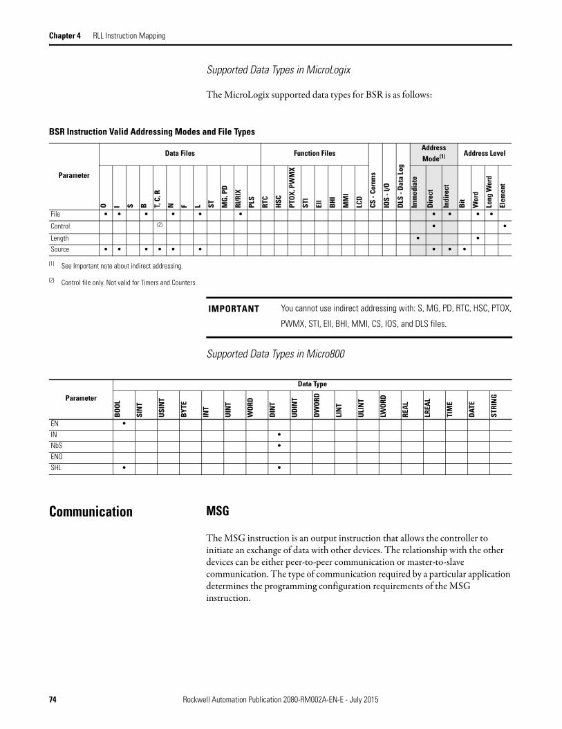
Chapter 4 RLL Instruction Mapping
Supported Data Types in MicroLogix
The MicroLogix supported data types for BSR is as follows:
Supported Data Types in Micro800
Communication MSG
The MSG instruction is an output instruction that allows the controller to initiate an exchange of data with other devices. The relationship with the other devices can be either peer-to-peer communication or master-to-slave communication. The type of communication required by a particular application determines the programming configuration requirements of the MSG instruction.
BSR Instruction Valid Addressing Modes and File Types
Parameter
Data Files Function Files
CS -
Com
ms
IOS
- I/O
DLS
- D
ata
Log
Address Mode(1) Address Level
O I S B T, C
, R
N F L ST MG
, PD
RI/R
IX
PLS
RTC
HSC
PTO
X, P
WM
X
STI
EII
BHI
MM
I
LCD
Imm
edia
te
Dire
ct
Indi
rect
Bit
Wor
d
Long
Wor
d
Elem
ent
File • • • • • • • • • •
Control (2) • •
Length • •
Source • • • • • • • • •
(1) See Important note about indirect addressing.
(2) Control file only. Not valid for Timers and Counters.
IMPORTANT You cannot use indirect addressing with: S, MG, PD, RTC, HSC, PTOX,
PWMX, STI, EII, BHI, MMI, CS, IOS, and DLS files.
Parameter
Data Type
BOO
L
SIN
T
USI
NT
BYT
E
INT
UIN
T
WOR
D
DIN
T
UDI
NT
DW
ORD
LIN
T
ULI
NT
LWO
RD
REA
L
LREA
L
TIM
E
DAT
E
STRI
NG
EN •
IN •
NbS •
ENO
SHL • •
74 Rockwell Automation Publication 2080-RM002A-EN-E - July 2015
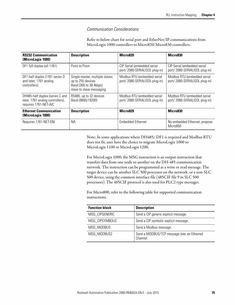
RLL Instruction Mapping Chapter 4
Communication Considerations
Refer to below chart for serial port and EtherNet/IP communications from MicroLogix 1000 controllers to Micro820/Micro830 controllers:
Note: In some applications where DH485/ DF1 is required and Modbus RTU does not fit, user have the choice to migrate MicroLogix 1000 to MicroLogix 1100 or MicroLogix 1200.
For MicroLogix 1000, the MSG instruction is an output instruction that transfers data from one node to another on the DH-485 communication network. The instruction can be programmed as a write or read message. The target device can be another SLC 500 processor on the network, or a non-SLC 500 device, using the common interface file (485CIF file 9 in SLC 500 processors). The 485CIF protocol is also used for PLC2 type messages.
For Micro800, refer to the following table for supported communication instructions.
RS232 Communication (MicroLogix 1000)
Description Micro820 Micro830
DF1 full duplex (all 1761) Point to Point CIP Serial (embedded serial port/ 2080-SERIALISOL plug-in)
CIP Serial (embedded serial port/ 2080-SERIALISOL plug-in)
DF1 half duplex (1761 series D and later, 1761 analog controllers)
Single master, multiple slaves up to 255 devicesBaud (300 to 38.4kbps)slave to slave messaging
Modbus RTU (embedded serial port/ 2080-SERIALISOL plug-in)
Modbus RTU (embedded serial port/ 2080-SERIALISOL plug-in)
DH485 half duplex (series C and later, 1761 analog controllers), requires 1761-NET-AIC
RS485, up to 32 devicesBaud (9600/19200)
Modbus RTU (embedded serial port/ 2080-SERIALISOL plug-in)
Modbus RTU (embedded serial port/ 2080-SERIALISOL plug-in)
Ethernet Communication (MicroLogix 1000)
Description Micro820 Micro830
Requires 1761-NET-ENI NA Embedded Ethernet No embedded Ethernet, propose Micro850
Function block Description
MSG_CIPGENERIC Send a CIP generic explicit message.
MSG_CIPSYMBOLIC Send a CIP symbolic explicit message.
MSG_MODBUS Send a Modbus message.
MSG_MODBUS2 Send a MODBUS/TCP message over an Ethernet Channel.
Rockwell Automation Publication 2080-RM002A-EN-E - July 2015 75

Chapter 4 RLL Instruction Mapping
The following table lists the communication protocols supported by the Modbus and CIP message function blocks.
Comparison The MicroLogix supported data types for EQU, NEQ, GRT, LES, GEQ and LEQ are as follows:
Messaging Protocol Communication media Use this function block
Modbus/RTU client and server
Through a Serial port configured as Modbus RTU
MSG_MODBUS
Modbus/TCP client and server
Over the Ethernet instead of through a serial port
MSG_MODBUS2
Ethernet IP client and server Through an embedded Ethernet channel
MSG_CIPSYMBOLICMSG_CIPGENERIC
CIP Serial client and server Ethernet cable or Serial cable
MSG_CIPSYMBOLIC
ASCII Through an RS-232 port configured with an ASCII driver
See ASCII serial port instructions
EQU, NEQ, GRT, LES, GEQ and LEQ Instructions Valid Addressing Modes and File Types
Parameter
Data Files Function Files(1)CS
- Co
mm
s
IOS
- I/O
DLS
- D
ata
Log
Address Mode(2) Address Level
O I S B T, C
, R
N F ST L MG
, PD
RI/R
IX
PLS
RTC
HSC
(3)
PTO
X, P
WM
X
STI
EII
BHI
MM
I
LCD
Imm
edia
te
Dir
ect
Indi
rect
Bit
Wor
d
Long
Wor
d
Elem
ent
Source A • • • • • • • • • • • • • • • • • • • • • • • • •
Source B • • • • • • • • • • • • • • • • • • • • • • • • •
(1) PTOX and PWMX files are only for use with MicroLogix 1400 BXB or BXBA unit.
(2) See Important note about indirect addressing.
(3) Only use the High Speed Counter Accumulator (HSC.ACC) for Source A in GRT, LES, GEQ and LEQ instructions.
IMPORTANT You cannot use indirect addressing with: S, MG, PD, RTC, HSC, PTOX,
PWMX, STI, EII, BHI, MMI, CS, IOS, and DLS files.
76 Rockwell Automation Publication 2080-RM002A-EN-E - July 2015

RLL Instruction Mapping Chapter 4
EQU
Description
Compare two data types.
Functional Block Diagram
Instruction Parameters
CCW Limitations
Both the inputs must be of the same data type.
Behavioral Differences
None
Supported Data Types in MicroLogix
Refer to Comparison on page 76
RSLogix 500 CCW
IO Type RSLogix 500 Parameters CCW Parameters
Input Level Triggered Input EN Level Triggered Input
T When rung conditions are true, this output instruction performs equality comparison operation.
When EN is TRUE, then comparison is computed.
F No operation No operation
Input Source A Files which contain value i1 Source variable
Input Source B Immediate value or files which contain value
i2 Source variable
Output When the values are equal the rung goes true and the output is energized (provided no other forces affect the rung's status).
o1 TRUE if Source A and B are equal
Output Rung enable output ENO Rung enable output
Rockwell Automation Publication 2080-RM002A-EN-E - July 2015 77

Chapter 4 RLL Instruction Mapping
Supported Data Types in Micro800
NEQ
Description
Compare two data types for inequality.
Functional Block Diagram
Instruction Parameters
Parameter
Data Type
BOO
L
SIN
T
USI
NT
BYT
E
INT
UIN
T
WO
RD
DIN
T
UD
INT
DWO
RD
LIN
T
ULI
NT
LWOR
D
REA
L
LREA
L
TIM
E
DATE
STRI
NG
EN •
i1 • • • • • • • • • • • • • • •(1) • •
i2 • • • • • • • • • • • • • • •(1) • •
ENO •
o1 •
(1) The Time input applies to the ST, LD and FBD languages.
RSLogix 500 CCW
IO Type RSLogix 500 Parameters CCW Parameters
Input Level Triggered Input EN Level Triggered Input
T When rung conditions are true, this output instruction performs inequality comparison operation.
When EN is TRUE, then comparison is computed. If EN is FALSE, there is no computation.
F No operation No operation
Input Source A Files which contain value i1 Source variable
Input Source B Immediate value or files which contain value
i2 Source variable
Output When the values are not equal the rung goes true and the output is energized.
o1 TRUE if Source A and B are unequal
Output Rung enable output ENO Rung enable output
78 Rockwell Automation Publication 2080-RM002A-EN-E - July 2015
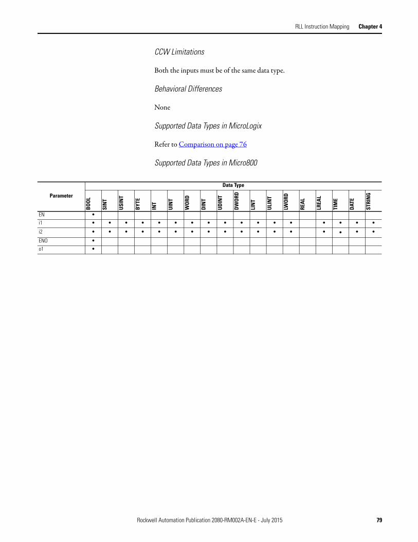
RLL Instruction Mapping Chapter 4
CCW Limitations
Both the inputs must be of the same data type.
Behavioral Differences
None
Supported Data Types in MicroLogix
Refer to Comparison on page 76
Supported Data Types in Micro800
Parameter
Data Type
BOO
L
SIN
T
USI
NT
BYT
E
INT
UIN
T
WOR
D
DIN
T
UDI
NT
DW
ORD
LIN
T
ULI
NT
LWOR
D
REA
L
LREA
L
TIM
E
DAT
E
STRI
NG
EN •
i1 • • • • • • • • • • • • • • • • •
i2 • • • • • • • • • • • • • • • • •
ENO •
o1 •
Rockwell Automation Publication 2080-RM002A-EN-E - July 2015 79

Chapter 4 RLL Instruction Mapping
LES
Description
This instruction checks whether one value is less than another value.
Functional Block Diagram
Instruction Parameters
CCW Limitations
Both the inputs must be of the same data type.
Behavioral Differences
None
Supported Data Types in MicroLogix
Refer to Comparison on page 76
RSLogix 500 CCW
IO Type RSLogix 500 Parameters CCW Parameters
Input Level Triggered Input EN Level Triggered Input
T When rung conditions are true, this output instruction performs comparison operation.
When EN is TRUE, then comparison is computed. If EN is FALSE, there is no computation
F No operation No operation
Input Source A Files which contain value i1 Source variable
Input Source B Immediate value or files which contain value
i2 Source variable
Output When the value of Source A is less than the value in Source B, the rung goes true and the output is energized (provided no other forces affect the rung's status).
o1 TRUE if Source A is less than Source B
Output Rung enable output ENO Rung enable output
80 Rockwell Automation Publication 2080-RM002A-EN-E - July 2015

RLL Instruction Mapping Chapter 4
Supported Data Types in Micro800
LEQ
Description
This instruction checks whether one value is less than or equal to another value.
Functional Block Diagram
Instruction Parameters
Parameter
Data Type
BOO
L
SIN
T
USI
NT
BYT
E
INT
UIN
T
WO
RD
DIN
T
UD
INT
DWO
RD
LIN
T
ULI
NT
LWOR
D
REA
L
LREA
L
TIM
E
DATE
STRI
NG
EN •
i1 • • • • • • • • • • • • • • • •
i2 • • • • • • • • • • • • • • • •
ENO •
o1 •
RSLogix 500 CCW
IO Type RSLogix 500 Parameters CCW Parameters
Input Level Triggered Input EN Level Triggered Input
T When rung conditions are true, this output instruction performs comparison operation.
When EN is TRUE, then comparison is computed. If EN is FALSE, there is no computation
F No operation No operation
Input Source A Files which contain value i1 Source variable
Input Source B Immediate value or files which contain value
i2 Source variable
Output When the value of Source A is less than or equal to the value in Source B, the rung goes true and the output is energized (provided no other forces affect the rung's status).
o1 TRUE if Source A is less than or equal to Source B
Output Rung enable output ENO Rung enable output
Rockwell Automation Publication 2080-RM002A-EN-E - July 2015 81

Chapter 4 RLL Instruction Mapping
CCW Limitations
Both the inputs must be of the same data type.
Behavioral Differences
None
Supported Data Types in MicroLogix
Refer to Comparison on page 76
Supported Data Types in Micro800
Parameter
Data Types
BOOL
SIN
T
USI
NT
BYT
E
INT
UIN
T
WO
RD
DIN
T
UD
INT
DW
ORD
LIN
T
ULI
NT
LWOR
D
REA
L
LREA
L
TIM
E
DATE
STRI
NG
Imm
edia
te
Dir
ect
EN •
i1 • • • • • • • • • • • • • • •(1) • •
i2 • • • • • • • • • • • • • • •(1) • •
ENO •o1 •
(1) The Time input applies to the ST, LD and FBD languages.
82 Rockwell Automation Publication 2080-RM002A-EN-E - July 2015

RLL Instruction Mapping Chapter 4
GRT
Description
This instruction checks whether one value is greater than another value.
Functional Block Diagram
Instruction Parameters
CCW Limitations
Both the inputs must be of the same data type.
Behavioral Differences
None
Supported Data Types in MicroLogix
Refer to Comparison on page 76
RSLogix 500 CCW
IO Type RSLogix 500 Parameters CCW Parameters
Input Level Triggered Input EN Level Triggered Input
T When rung conditions are true, this output instruction performs comparison operation.
When EN is TRUE, then equality comparison is computed. If EN is FALSE, there is no computation
F No operation No operation
Input Source A Files which contain value i1 Source variable
Input Source B Immediate value or files which contain value
i2 Source variable
Output When the value of Source A is greater than the value in Source B, the rung goes true and the output is energized (provided no other forces affect the rung's status).
o1 TRUE if Source A is greater than Source B
Output Rung enable output ENO Rung enable output
Rockwell Automation Publication 2080-RM002A-EN-E - July 2015 83

Chapter 4 RLL Instruction Mapping
Supported Data Types in Micro800
GEQ
Description
This instruction checks whether one value is greater than or equal to another value.
Functional Block Diagram
Parameter
Data Type
BOO
L
SIN
T
USI
NT
BYT
E
INT
UIN
T
WO
RD
DIN
T
UD
INT
DWO
RD
LIN
T
ULI
NT
LWOR
D
REA
L
LREA
L
TIM
E
DATE
STRI
NG
EN •
i1 • • • • • • • • • • • • • • • • •
i2 • • • • • • • • • • • • • • • • •
ENO •
o1 •
RSLogix 500 CCW
84 Rockwell Automation Publication 2080-RM002A-EN-E - July 2015
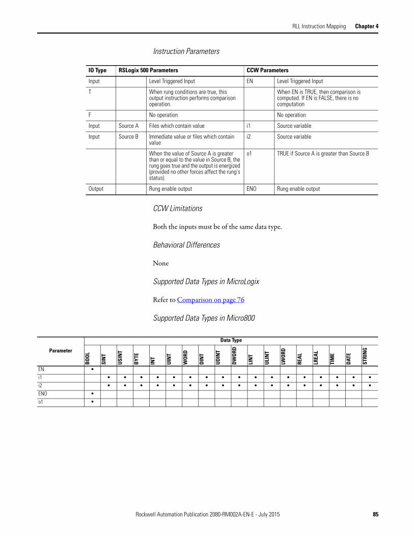
RLL Instruction Mapping Chapter 4
Instruction Parameters
CCW Limitations
Both the inputs must be of the same data type.
Behavioral Differences
None
Supported Data Types in MicroLogix
Refer to Comparison on page 76
Supported Data Types in Micro800
IO Type RSLogix 500 Parameters CCW Parameters
Input Level Triggered Input EN Level Triggered Input
T When rung conditions are true, this output instruction performs comparison operation.
When EN is TRUE, then comparison is computed. If EN is FALSE, there is no computation
F No operation No operation
Input Source A Files which contain value i1 Source variable
Input Source B Immediate value or files which contain value
i2 Source variable
When the value of Source A is greater than or equal to the value in Source B, the rung goes true and the output is energized (provided no other forces affect the rung's status).
o1 TRUE if Source A is greater than Source B
Output Rung enable output ENO Rung enable output
Parameter
Data Type
BOO
L
SIN
T
USI
NT
BYT
E
INT
UIN
T
WOR
D
DIN
T
UD
INT
DWO
RD
LIN
T
ULI
NT
LWOR
D
REA
L
LREA
L
TIM
E
DATE
STRI
NG
EN •
i1 • • • • • • • • • • • • • • • • •
i2 • • • • • • • • • • • • • • • • •
ENO •
o1 •
Rockwell Automation Publication 2080-RM002A-EN-E - July 2015 85

Chapter 4 RLL Instruction Mapping
LIM
Description
This instruction is used to compare a value with defined lower and upper limits.
Functional Block Diagram
Instruction Parameters
RSLogix 500 CCW
IO Type RSLogix 500 Parameters CCW Parameters
Input Level Triggered Input EN Level Triggered Input
T When rung conditions are true, this LIM instruction performs comparison operation.
When EN is TRUE, then LIM comparison is computed. If EN is FALSE, there is no computation
F No operation No operation
Input Test Files which contain value X Source variable
Input High Limit Immediate value or files which contain value
H Source variable
Input Low Limit Immediate value or files which contain value
L Source variable
Input EPS Hysteresis Value (cannot be 0)
Output TRUE when the Test value is within or equal to limits
Output QH TRUE if X is above High limit
Output Q TRUE if X is out of limits
Output QL TRUE if X is below Low limit
Output Rung enable output ENO Rung enable output
86 Rockwell Automation Publication 2080-RM002A-EN-E - July 2015

RLL Instruction Mapping Chapter 4
CCW Limitations
Only allows Floating Point values.
Behavioral Differences
The behavioral differences between MicroLogix and Micro800 are as follows:
Case 1: Low Limit <= High Limit
Case 2: Low Limit > High Limit
LIM_ALRM Results
The behavior of the output Q is according to the graph shown below:
LIM Results
The output is TRUE when the Test value is within or equal to the Lower and Upper limit, i.e.
Lower Limit <= Test Value <= Upper Limit.
Otherwise the output is FALSE.
LIM_ALRM Results
The behavior of the output Q is according to the graph shown below:
LIM Results
The output is FALSE when the Test value is within the Upper and Lower limit, i.e.
Upper Limit < Test value < Lower Limit.
Otherwise the output is TRUE.
Rockwell Automation Publication 2080-RM002A-EN-E - July 2015 87

Chapter 4 RLL Instruction Mapping
Supported Data Types in MicroLogix
The MicroLogix supported data types for LIM is as follows:
Supported Data Types in Micro800
LIM Instruction Valid Addressing Modes and File Types
Parameter
Data Files Function Files(1)
CS -
Com
ms
IOS
- I/O
DLS
- D
ata
Log
Address
Mode(2) Address Level
O I S B T, C
, R
N F ST L MG
, PD
RI/R
IX
PLS
RTC
HSC
PTO
X, P
WM
X
STI
EII
BHI
MM
I
LCD
Imm
edia
te
Dir
ect
Indi
rect
Bit
Wor
d
Long
Wor
d
Elem
ent
Low Limit • • • • • • • • • • • • • • • • • • • • • • • • •
Test • • • • • • • • • • • • • • • • • • • • • • • • •
High Limit • • • • • • • • • • • • • • • • • • • • • • • • •
(1) PTOX and PWMX files are only for use with MicroLogix 1400 BXB or BXBA unit.
(2) See Important note about indirect addressing.
IMPORTANT You cannot use indirect addressing with: S, MG, PD, RTC, HSC, PTOX,
PWMX, STI, EII, BHI, MMI, CS, IOS, and DLS files.
Parameter
Data Type
BOOL
SIN
T
USIN
T
BYTE
INT
UIN
T
WO
RD
DIN
T
UD
INT
DW
ORD
LIN
T
ULI
NT
LWO
RD
REA
L
LREA
L
TIM
E
DATE
STRI
NG
EN •
H •
X •
L •
EPS •
QH • •
Q •
QL •
88 Rockwell Automation Publication 2080-RM002A-EN-E - July 2015

RLL Instruction Mapping Chapter 4
Control JMP
Description
Jump to label.
Functional Block Diagram
Instruction Parameters
CCW Limitations
None
Behavioral Differences
None
Supported Data Types in MicroLogix
Not applicable
RSLogix 500 CCW
IO Type RSLogix 500 Parameters CCW Parameters
Input Level Triggered Input Level Triggered Input
T When the rung condition for this output instruction is true, the processor jumps forward or backward to the corresponding label instruction (LBL) and resumes program execution at the label. More than one JMP instruction can jump to the same label. Jumping forward to a label saves program scan time by omitting a program segment until needed. Jumping backward lets the controller execute program segments repeatedly.
When the connection on the left of the Jump is TRUE, the diagram at the label is executed.
F When the rung state is false, execution shall proceed to the instruction immediately following the JMP instruction.
When the connection on the left of the Jump is FALSE, the next instruction after the jump is executed.
Rockwell Automation Publication 2080-RM002A-EN-E - July 2015 89

Chapter 4 RLL Instruction Mapping
LBL
Description
Labels are used as a target for jump instructions or to control the execution of the diagram.
Functional Block Diagram
Instruction Parameters
CCW Limitations
None
Behavioral Differences
None
Supported Data Types in MicroLogix
Not applicable
RSLogix 500 CCW
IO Type RSLogix 500 Parameters CCW Parameters
Input This input instruction is the target of the JMP instruction having the same label number. It is always evaluated as true or logic 1.
Provide the label on the rung for the jump instruction to move the execution to this rung.
90 Rockwell Automation Publication 2080-RM002A-EN-E - July 2015

RLL Instruction Mapping Chapter 4
RET
Description
This output instruction marks the end of subroutine execution or the end of the subroutine file.
Functional Block Diagram
Instruction Parameters
CCW Limitations
None
Behavioral Differences
None
Supported Data Types in MicroLogix
Not applicable
RSLogix 500 CCW
IO Type RSLogix 500 Parameters CCW Parameters
Input Level Triggered Input Level Triggered Input
T When the rung state is true, execution shall revert to the next instruction in the program either following the calling JSR instruction (subroutine call) or to the point where a user interrupt or user fault routine started executing.
When the left connection of the rung is in TRUE state, the diagram ends without executing the instructions that follow it.
F When the rung state is false, execution shall proceed to the instruction immediately following the RET instruction.
When the left side of the rung is FALSE, the instructions below it continue to get executed.
Rockwell Automation Publication 2080-RM002A-EN-E - July 2015 91
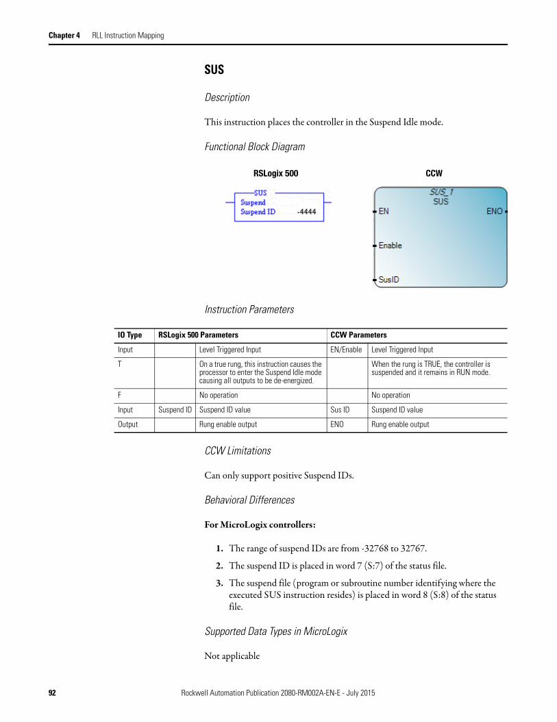
Chapter 4 RLL Instruction Mapping
SUS
Description
This instruction places the controller in the Suspend Idle mode.
Functional Block Diagram
Instruction Parameters
CCW Limitations
Can only support positive Suspend IDs.
Behavioral Differences
For MicroLogix controllers:
1. The range of suspend IDs are from -32768 to 32767.
2. The suspend ID is placed in word 7 (S:7) of the status file.
3. The suspend file (program or subroutine number identifying where the executed SUS instruction resides) is placed in word 8 (S:8) of the status file.
Supported Data Types in MicroLogix
Not applicable
RSLogix 500 CCW
IO Type RSLogix 500 Parameters CCW Parameters
Input Level Triggered Input EN/Enable Level Triggered Input
T On a true rung, this instruction causes the processor to enter the Suspend Idle mode causing all outputs to be de-energized.
When the rung is TRUE, the controller is suspended and it remains in RUN mode.
F No operation No operation
Input Suspend ID Suspend ID value Sus ID Suspend ID value
Output Rung enable output ENO Rung enable output
92 Rockwell Automation Publication 2080-RM002A-EN-E - July 2015

RLL Instruction Mapping Chapter 4
Supported Data Types for Micro800
TND
Description
This instruction is used to progressively debug a program, or conditionally omit the balance of your current program file or subroutines.
Functional Block Diagram
Instruction Parameters
CCW Limitations
None
Parameter
Data Type
BOO
L
SIN
T
USI
NT
BYT
E
INT
UIN
T
WO
RD
DIN
T
UD
INT
DWO
RD
LIN
T
ULI
NT
LWOR
D
REA
L
LREA
L
TIM
E
DATE
STRI
NG
EN/ENABLE •
SusID •
ENO •
RSLogix 500 CCW
IO Type RSLogix 500 Parameters CCW Parameters
Input Level Triggered Input EN/Enable Level Triggered Input
T This instruction, when its rung is true, stops the controller from scanning the rest of the program file, updates the I/O, and resumes scanning at rung 0 of the main program.
Same
F No operation No operation
Output If TRUE, the function is performed TND/ENO Same as TND
Rockwell Automation Publication 2080-RM002A-EN-E - July 2015 93
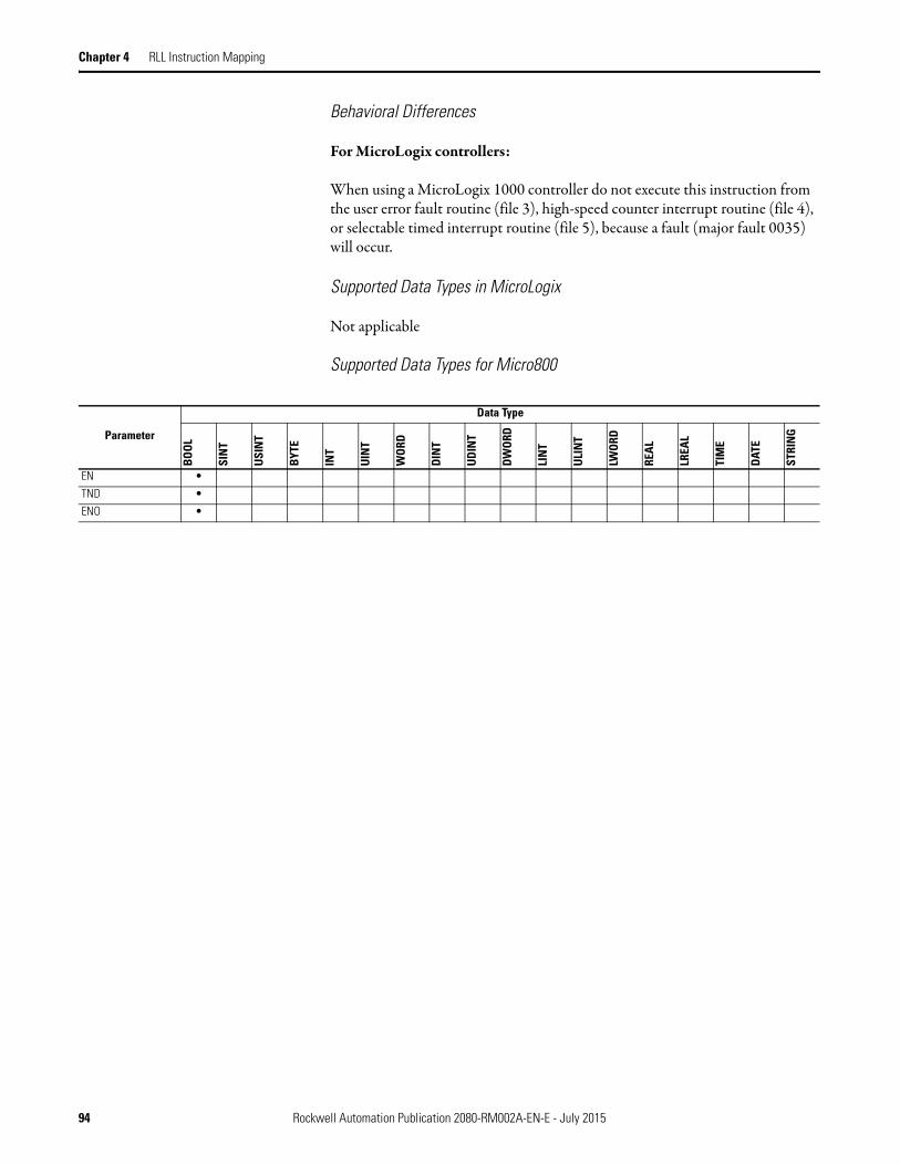
Chapter 4 RLL Instruction Mapping
Behavioral Differences
For MicroLogix controllers:
When using a MicroLogix 1000 controller do not execute this instruction from the user error fault routine (file 3), high-speed counter interrupt routine (file 4), or selectable timed interrupt routine (file 5), because a fault (major fault 0035) will occur.
Supported Data Types in MicroLogix
Not applicable
Supported Data Types for Micro800
Parameter
Data Type
BOOL
SIN
T
USI
NT
BYT
E
INT
UIN
T
WO
RD
DIN
T
UD
INT
DW
ORD
LIN
T
ULI
NT
LWOR
D
REA
L
LREA
L
TIM
E
DATE
STRI
NG
EN •
TND •
ENO •
94 Rockwell Automation Publication 2080-RM002A-EN-E - July 2015

RLL Instruction Mapping Chapter 4
I/O Related Interrupt IIM
Description
This instruction is used to update the input data without waiting for the next input scan to begin.
Functional Block Diagram
Instruction Parameters
CCW Limitations
1. Does not allow masking of the data bits that are read from the input slot.
2. Cannot specify individual words in a particular slot.
RSLogix 500 CCW
IO Type RSLogix 500 Parameters CCW Parameters
Input Level Triggered Input EN/Enable Level Triggered Input
T When the rung containing this instruction is true, the program scan cycle is interrupted. Each word of data starting at the specified Input has Mask applied to it. The masked data is then transferred to the input file, making the masked data available to instructions following this instruction in the ladder program. The program scan then resumes.
When the rung condition is TRUE, it updates the input data without waiting for the next input scan
F No operation No operation
Input Slot Indicates the slot or a particular word in a slot.
InputSlot Slot number
Input Mask Immediate value or files which contain value
Not supported
Input InputType 0: Embedded, 1: Plug-in input
Output Sts
Output Rung enable output ENO Rung enable output
Rockwell Automation Publication 2080-RM002A-EN-E - July 2015 95

Chapter 4 RLL Instruction Mapping
Behavioral Differences
For MicroLogix controllers:
1. IIM instruction cannot be used with expansion I/O slots.
2. Mask Value - Can specify with a constant or register address. The constant can be binary, decimal, or hexadecimal. For the mask, a (1) in an input's bit position passes data from the source to the destination. A (0) inhibits data from passing from the source to the destination.
Supported Data Types in MicroLogix
The MicroLogix supported data types for IIM is as follows:
Supported Data Types for Micro800
IIM Instruction Valid Addressing Modes and File Types
Parameter
Data Files Function Files
CS -
Com
ms
IOS
- I/O
DLS
- Da
ta L
og
Address Mode
Address Level
O I S B T, C
, R
N F ST L MG
, PD
RI/R
IX
PLS
RTC
HSC
PTO
X, P
WM
X
STI
EII
BHI
MM
I
LCD
Imm
edia
te
Dire
ct
Indi
rect
Bit
Wor
d
Long
Wor
d
Elem
ent
Slot • • • •
Mask • • • • • • • • •
Length •
Parameter
Data Type
BOO
L
SIN
T
USI
NT
BYT
E
INT
UIN
T
WO
RD
DIN
T
UDIN
T
DW
ORD
LIN
T
ULI
NT
LWOR
D
REA
L
LREA
L
TIM
E
DATE
STRI
NG
EN/ENABLE •
InputType •
InputSlot •
Sts •
ENO •
96 Rockwell Automation Publication 2080-RM002A-EN-E - July 2015

RLL Instruction Mapping Chapter 4
IOM
Description
This instruction is used to update the outputs without waiting for the next output scan.
Functional Block Diagram
Instruction Parameters
CCW Limitations
1. Does not allow masking of the data bits that are written to the output slot.
2. Cannot specify individual words in a particular slot.
RSLogix 500 CCW
IO Type RSLogix 500 Parameters CCW Parameters
Input Level Triggered Input EN/Enable Level Triggered Input
T When the rung containing this instruction is true, the program scan cycle is interrupted. Each word of data from the specified output file has Mask applied to it. The masked data is then transferred to the specified Output. The program scan then resumes.
When the rung condition is TRUE, it updates the output without waiting for the next input scan
F No operation No operation
Input Slot Indicates the slot or a particular word in a slot.
Output Slot Slot number
Input Mask Immediate value or files which contain value
i2 Not supported
Input OutputType 0: Embedded, 1: Plug-in input
Output Sts
Output Rung enable output ENO Rung enable output
Rockwell Automation Publication 2080-RM002A-EN-E - July 2015 97

Chapter 4 RLL Instruction Mapping
Behavioral Differences
For MicroLogix controllers:
1. IOM instruction cannot be used with expansion I/O slots.
2. Mask Value - Can specify with a constant or register address. The constant can be binary, decimal, or hexadecimal. For the mask, a (1) in an input's bit position passes data from the source to the destination. A (0) inhibits data from passing from the source to the destination.
Supported Data Types in MicroLogix
The MicroLogix supported data types for IOM is as follows:
Supported Data Types for Micro800
IOM Instruction Valid Addressing Modes and File Types
Parameter
Data Files Function Files
CS -
Com
ms
IOS
- I/O
DLS
- Da
ta L
og
Address Mode
Address Level
O I S B T, C
, R
N F ST L MG
, PD
RI/R
IX
PLS
RTC
HSC
PTO
X, P
WM
X
STI
EII
BHI
MM
I
LCD
Imm
edia
te
Dire
ct
Indi
rect
Bit
Wor
d
Long
Wor
d
Elem
ent
Slot • • • •
Mask • • • • • • • • •
Length •
Parameter
Data Type
BOO
L
SIN
T
USI
NT
BYT
E
INT
UIN
T
WO
RD
DIN
T
UDIN
T
DW
ORD
LIN
T
ULI
NT
LWOR
D
REA
L
LREA
L
TIM
E
DATE
STRI
NG
EN/ENABLE •
OutputType •
OutputSlot •
Sts •
ENO •
98 Rockwell Automation Publication 2080-RM002A-EN-E - July 2015

RLL Instruction Mapping Chapter 4
Selectable Timed Interrupts STD
Description
Disable timer interrupt.
Functional Block Diagram
Instruction Parameters
CCW Limitations
None
Behavioral Differences
None
Supported Data Types in MicroLogix
Not applicable
RSLogix 500 CCW
IO Type RSLogix 500 Parameters CCW Parameters
Input Level Triggered Input EN/Enable Level Triggered Input
T When true, this instruction resets the STI enable bit and prevents the STI subroutine from executing.
Disables the interrupt
F When the rung goes false, the STI enable bit remains reset until a true STS or STE instruction is executed. The STI timer continues to operate while the enable bit is reset.
No operation
IRQ Type Select the interrupt type
Output Rung enable output UID/ENO Rung enable output
IRQ Type Select the interrupt type
Rockwell Automation Publication 2080-RM002A-EN-E - July 2015 99
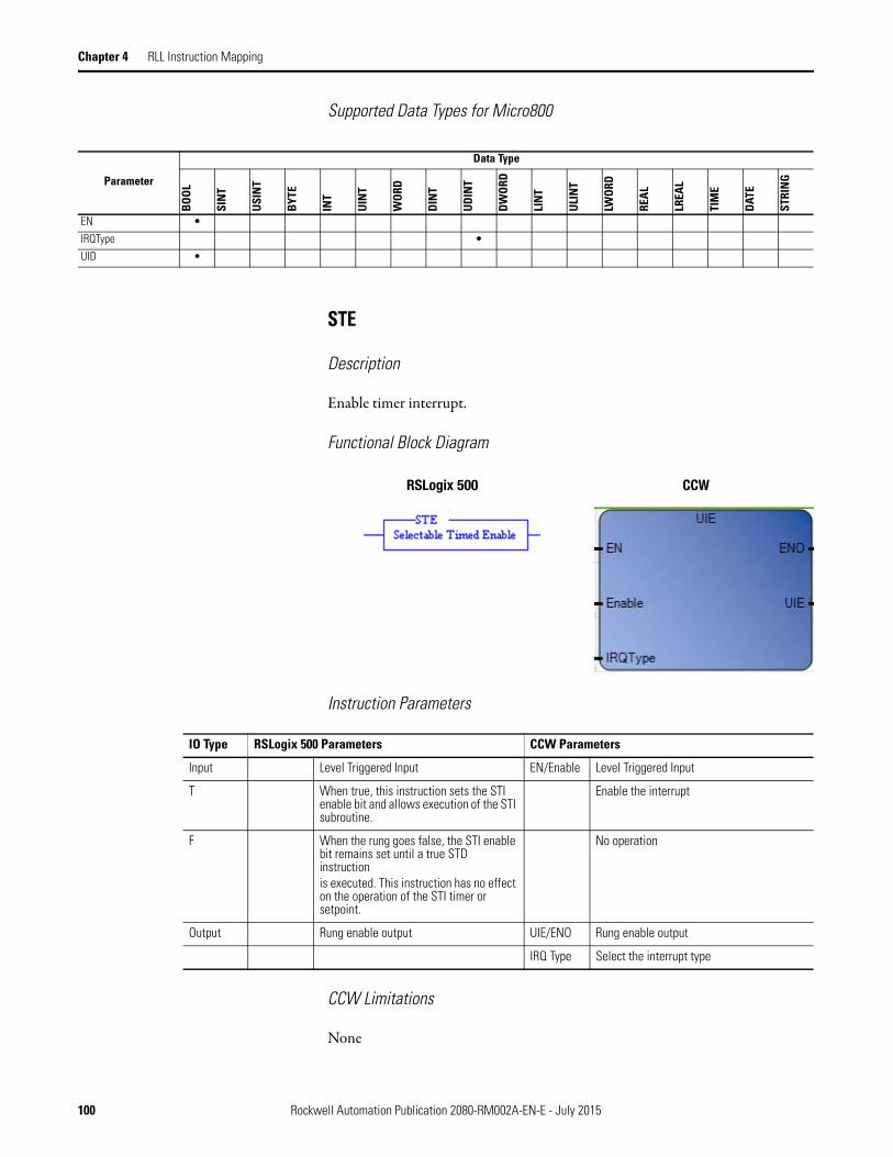
Chapter 4 RLL Instruction Mapping
Supported Data Types for Micro800
STE
Description
Enable timer interrupt.
Functional Block Diagram
Instruction Parameters
CCW Limitations
None
Parameter
Data Type
BOO
L
SIN
T
USI
NT
BYT
E
INT
UIN
T
WO
RD
DIN
T
UD
INT
DWO
RD
LIN
T
ULI
NT
LWOR
D
REA
L
LREA
L
TIM
E
DATE
STRI
NG
EN •
IRQType •
UID •
RSLogix 500 CCW
IO Type RSLogix 500 Parameters CCW Parameters
Input Level Triggered Input EN/Enable Level Triggered Input
T When true, this instruction sets the STI enable bit and allows execution of the STI subroutine.
Enable the interrupt
F When the rung goes false, the STI enable bit remains set until a true STD instructionis executed. This instruction has no effect on the operation of the STI timer or setpoint.
No operation
Output Rung enable output UIE/ENO Rung enable output
IRQ Type Select the interrupt type
100 Rockwell Automation Publication 2080-RM002A-EN-E - July 2015
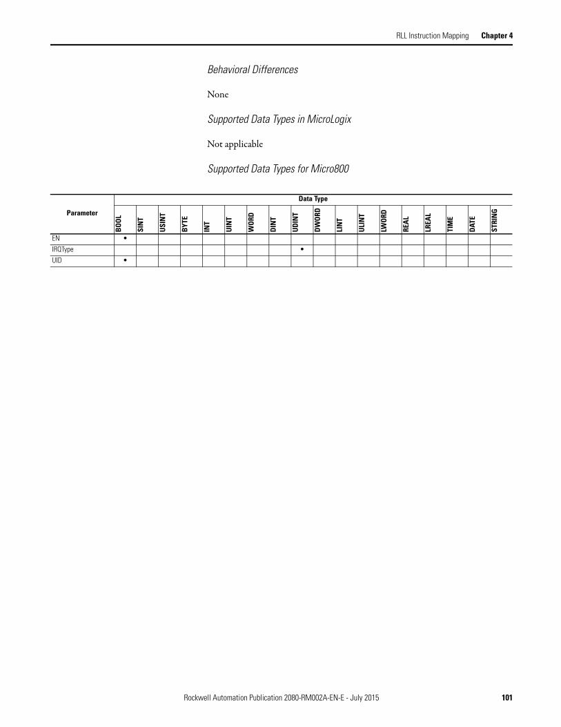
RLL Instruction Mapping Chapter 4
Behavioral Differences
None
Supported Data Types in MicroLogix
Not applicable
Supported Data Types for Micro800
Parameter
Data Type
BOO
L
SIN
T
USI
NT
BYT
E
INT
UIN
T
WOR
D
DIN
T
UDI
NT
DW
ORD
LIN
T
ULI
NT
LWOR
D
REA
L
LREA
L
TIM
E
DAT
E
STRI
NG
EN •
IRQType •
UID •
Rockwell Automation Publication 2080-RM002A-EN-E - July 2015 101
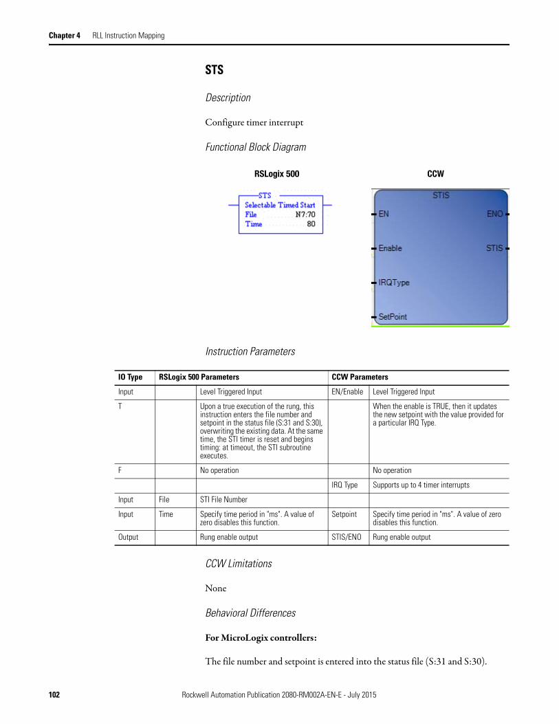
Chapter 4 RLL Instruction Mapping
STS
Description
Configure timer interrupt
Functional Block Diagram
Instruction Parameters
CCW Limitations
None
Behavioral Differences
For MicroLogix controllers:
The file number and setpoint is entered into the status file (S:31 and S:30).
RSLogix 500 CCW
IO Type RSLogix 500 Parameters CCW Parameters
Input Level Triggered Input EN/Enable Level Triggered Input
T Upon a true execution of the rung, this instruction enters the file number and setpoint in the status file (S:31 and S:30), overwriting the existing data. At the same time, the STI timer is reset and begins timing: at timeout, the STI subroutine executes.
When the enable is TRUE, then it updates the new setpoint with the value provided for a particular IRQ Type.
F No operation No operation
IRQ Type Supports up to 4 timer interrupts
Input File STI File Number
Input Time Specify time period in "ms". A value of zero disables this function.
Setpoint Specify time period in "ms". A value of zero disables this function.
Output Rung enable output STIS/ENO Rung enable output
102 Rockwell Automation Publication 2080-RM002A-EN-E - July 2015
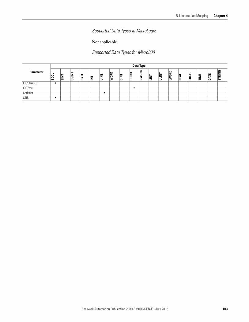
RLL Instruction Mapping Chapter 4
Supported Data Types in MicroLogix
Not applicable
Supported Data Types for Micro800
Parameter
Data Type
BOO
L
SIN
T
USI
NT
BYT
E
INT
UIN
T
WOR
D
DIN
T
UDI
NT
DW
ORD
LIN
T
ULI
NT
LWO
RD
REA
L
LREA
L
TIM
E
DAT
E
STRI
NG
EN/ENABLE •
IRQType •
SetPoint •
STIS •
Rockwell Automation Publication 2080-RM002A-EN-E - July 2015 103

Chapter 4 RLL Instruction Mapping
File Manipulation COP
Description
Copy a block of data from source to destination.
Functional Block Diagram
Instruction Parameters
RSLogix 500 CCW
IO Type RSLogix 500 Parameters CCW Parameters
Input When the rung condition is true, the instruction gets executed.
EN/Enable When the rung condition is TRUE, then the instruction is executed.
Input Source File address from where the data has to be copied
Src Source array data
Input Not supported SrcOffset Source offset value
Input Destination File address to which the data has to be copied
Dest Destination array data
Input Not supported DestOffset Destination offset value
Input Length Number of words to be copied from source to destination
Length Number of elements to copy.
Input Swap Swap the bytes
Output STS Status Values
Output Rung enable output ENO Rung enable output
104 Rockwell Automation Publication 2080-RM002A-EN-E - July 2015

RLL Instruction Mapping Chapter 4
CCW Limitations
If the source or destination is a String data type, the other party must also be a String data type, or a USINT (UCHAR and BYTE) data type. If it is not, a data type mismatch will be reported.
Behavioral Differences
For MicroLogix controllers:
The maximum length that can be copied depending on data type is as follows:
Supported Data Types in MicroLogix
The MicroLogix supported data types for COP is as follows:
Maximum Lengths for the COP Instruction
Source/Destination Data Type Range of Length Operand
1 word elements (i.e. word) 1…128
2 word elements (i.e. long word) 1…64
3 word elements (i.e. counter) 1…42
42 word elements (i.e. string) 1…3
COP Instruction Valid Addressing Modes and File Types
Parameter
Data Files Function Files
CS -
Com
ms
IOS
- I/O
DLS
- D
ata
Log
Address Mode(1) Address Level
O I S B T, C
, R
N F ST A L MG
, PD
RI/R
IX
PLS
RTC
HSC
PTO
X, P
WM
X
STI
EII
BHI
MM
I
LCD
Imm
edia
te
Dire
ct
Indi
rect
Bit
Wor
d
Long
Wor
d
Elem
ent
Source • • • • • • • • • • • • •
Destination • • • • • • • • • • • • •
Length •
(1) See Important note about indirect addressing.
IMPORTANT You cannot use indirect addressing with: S, MG, PD, RTC, HSC, PTOX,
PWMX, STI, EII, BHI, MMI, CS, IOS, and DLS files.
Rockwell Automation Publication 2080-RM002A-EN-E - July 2015 105

Chapter 4 RLL Instruction Mapping
Supported Data Types in Micro800
Math The MicroLogix supported data types for ADD, SUB, MUL, DIV, NEG and CLR are as follows:
Parameter
Data Type
BOO
L
SIN
T
USI
NT
BYT
E
INT
UIN
T
WO
RD
DIN
T
UD
INT
DWO
RD
LIN
T
ULI
NT
LWOR
D
REA
L
LREA
L
TIM
E
DATE
STRI
NG
EN/ENABLE •
Src • • • • • • • • • • • • • • • • • •
SrcOffst •
Dest • • • • • • • • • • • • • • • • •
DestOffset •
Length •
Swap •
STS •
ENO •
Math Instructions (ADD, SUB, MUL, DIV, NEG, CLR) Valid Addressing Modes and File Types
Parameter
Data Files Function Files(1)
CS -
Com
ms
IOS
- I/O
DLS
- D
ata
Log(2
)
Address Mode(3) Address Level
O I S B T, C
, R
N F ST L MG
, PD
RI/R
IX
PLS
RTC
HSC
PTO
X, P
WM
X
STI
EII
BHI
MM
I
LCD
Imm
edia
te
Dir
ect
Indi
rect
Bit
Wor
d
Long
Wor
d
Elem
ent
Source A • • • • • • • • • • • • • • • • • • • • • • • • • •
Source B • • • • • • • • • • • • • • • • • • • • • • • • • •
Destination • • • • • • • • • • • • • • • • • • • •
(1) PTOX and PWMX files are only for use with MicroLogix 1400 BXB or BXBA unit.
(2) The Data Log Status file can only be used for the following math instructions: ADD, SUB, MUL, DIV, NEG, and SCP.
(3) See Important note about indirect addressing.
IMPORTANT You cannot use indirect addressing with: S, MG, PD, RTC, HSC, PTOX,
PWMX, STI, EII, BHI, MMI, CS, IOS, and DLS files.
106 Rockwell Automation Publication 2080-RM002A-EN-E - July 2015

RLL Instruction Mapping Chapter 4
ADD
Description
Add two values.
Functional Block Diagram
Instruction Parameters
CCW Limitations
Only supports same data types for both input and output.
Behavioral Differences
For MicroLogix controllers:
1. If the destination bit receives a value less than -32,768 or greater than +32,767 (a number that requires more than 16 bits to represent), the processor sets S:0/1 (overflow bit) and S:5/0 (overflow trap bit, major error 0020). Bit S:5/0 in the program can be monitored.
RSLogix 500 CCW
IO Type RSLogix 500 Parameters CCW Parameters
Input Level Triggered Input EN Level Triggered Input
T When rung conditions are true, this output instruction adds Source A to Source B and stores the result at the destination address. If the rung is false, then there is no computation.
When EN is TRUE, then addition is computed. If EN is FALSE, there is no computation
F No operation No operation
Input Source A Immediate value or files which contain value
i1 Source variable
Input Source B Immediate value or files which contain value
i2 Source variable
Output Dest Contains the destination address o1 Destination variable
Output Rung enable output ENO Rung enable output
Rockwell Automation Publication 2080-RM002A-EN-E - July 2015 107

Chapter 4 RLL Instruction Mapping
If a MicroLogix processor (capable of 32-bit addition) is used, the math overflow bit (S:2/14) in the status file should be set. This causes the unsigned, truncated, least significant 16 bits to remain in the destination.
If this bit is not set and an underflow or overflow conditions occurs, the destination address will contain a 32767 (if the result is positive) or -32768 (if the result is negative).
2. This instruction impacts the status flags in the following way:
Supported Data Types in MicroLogix
Refer to Math on page 106.
Supported Data Types in Micro800
With this Bit: The Controller:S:0/0 Carry (C) sets if carry is generated; otherwise resetsS:0/1 Overflow (V) sets if overflow is detected at destination; otherwise resets.
On overflow, the minor error flag is also set. The value -32,768 or 32,767 is placed in the destination. If S:2/14 (math overflow selection bit) is set, then the unsigned, truncated overflow remains in the destination.
S:0/2 Zero (Z) sets if result is zero, otherwise resetsS:0/3 Sign (S) sets if result is negative, otherwise resets
Parameter
Data Type
BOO
L
SIN
T
USI
NT
BYT
E
INT
UIN
T
WOR
D
DIN
T
UDI
NT
DW
ORD
LIN
T
ULI
NT
LWOR
D
REA
L
LREA
L
TIM
E
DAT
E
STRI
NG
EN •
i1 • • • • • • • • • • • • • • • •
i2 • • • • • • • • • • • • • • • •
o1 • • • • • • • • • • • • • • • •
ENO •
108 Rockwell Automation Publication 2080-RM002A-EN-E - July 2015
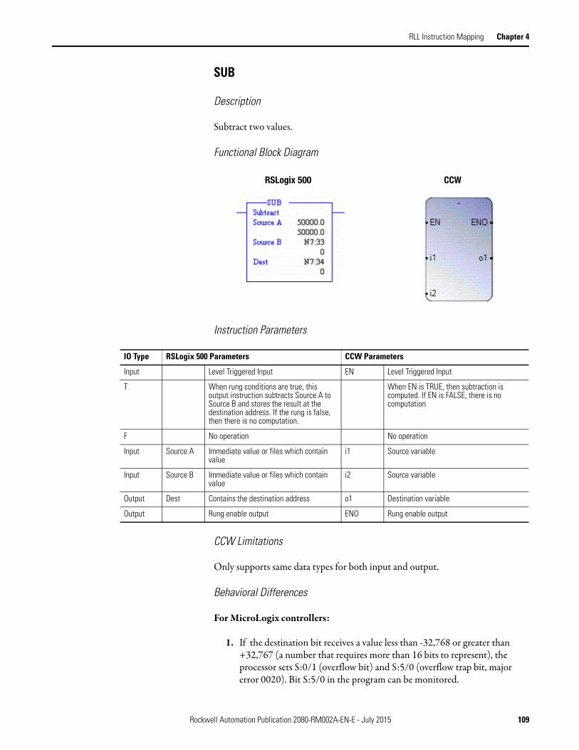
RLL Instruction Mapping Chapter 4
SUB
Description
Subtract two values.
Functional Block Diagram
Instruction Parameters
CCW Limitations
Only supports same data types for both input and output.
Behavioral Differences
For MicroLogix controllers:
1. If the destination bit receives a value less than -32,768 or greater than +32,767 (a number that requires more than 16 bits to represent), the processor sets S:0/1 (overflow bit) and S:5/0 (overflow trap bit, major error 0020). Bit S:5/0 in the program can be monitored.
RSLogix 500 CCW
IO Type RSLogix 500 Parameters CCW Parameters
Input Level Triggered Input EN Level Triggered Input
T When rung conditions are true, this output instruction subtracts Source A to Source B and stores the result at the destination address. If the rung is false, then there is no computation.
When EN is TRUE, then subtraction is computed. If EN is FALSE, there is no computation
F No operation No operation
Input Source A Immediate value or files which contain value
i1 Source variable
Input Source B Immediate value or files which contain value
i2 Source variable
Output Dest Contains the destination address o1 Destination variable
Output Rung enable output ENO Rung enable output
Rockwell Automation Publication 2080-RM002A-EN-E - July 2015 109

Chapter 4 RLL Instruction Mapping
If a MicroLogix processor (capable of 32-bit addition) is used, the math overflow bit (S:2/14) in the status file should be set. This causes the unsigned, truncated, least significant 16 bits to remain in the destination.
If this bit is not set and an underflow or overflow conditions occurs, the destination address will contain a 32767 (if the result is positive) or -32768 (if the result is negative).
2. This instruction impacts the status flags in the following way:
Supported Data Types in MicroLogix
Refer to Math on page 106.
For this instruction the source has to be a word (16 bits), so all relevant data types with word sizes are supported.
Supported Data Types in Micro800
With this Bit: The Controller:S:0/0 Carry (C) sets if borrow is generated; otherwise resetsS:0/1 Overflow (V) sets if underflow; otherwise reset. On underflow, the minor
error flag is also set. The value -32,768 or 32,767 is placed in the destination. If S:2/14 (math overflow selection bit) is set, then the unsigned, truncated overflow remains in the destination.
S:0/2 Zero (Z) sets if result is zero, otherwise resetsS:0/3 Sign (S) sets if result is negative, otherwise resets
Parameter
Data Type
BOO
L
SIN
T
USI
NT
BYT
E
INT
UIN
T
WOR
D
DIN
T
UDI
NT
DW
ORD
LIN
T
ULI
NT
LWOR
D
REA
L
LREA
L
TIM
E
DAT
E
STRI
NG
EN •
i1 • • • • • • • • • • • • • • •
i2 • • • • • • • • • • • • • • •
o1 • • • • • • • • • • • • • • •
ENO •
110 Rockwell Automation Publication 2080-RM002A-EN-E - July 2015
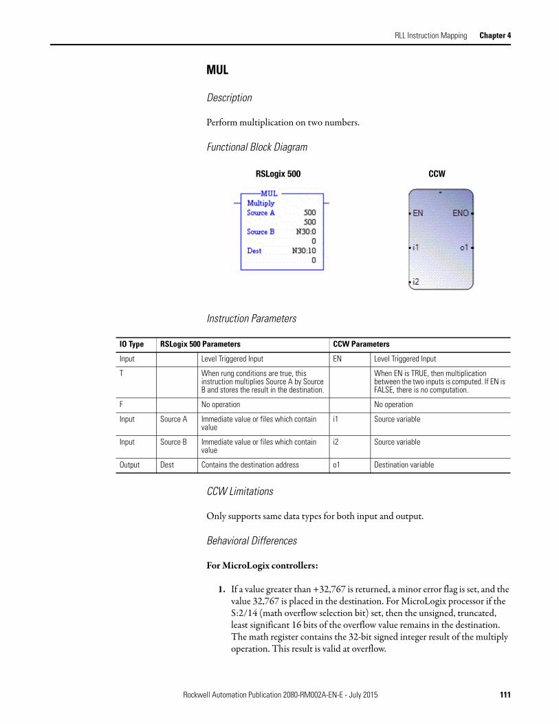
RLL Instruction Mapping Chapter 4
MUL
Description
Perform multiplication on two numbers.
Functional Block Diagram
Instruction Parameters
CCW Limitations
Only supports same data types for both input and output.
Behavioral Differences
For MicroLogix controllers:
1. If a value greater than +32,767 is returned, a minor error flag is set, and the value 32,767 is placed in the destination. For MicroLogix processor if the S:2/14 (math overflow selection bit) set, then the unsigned, truncated, least significant 16 bits of the overflow value remains in the destination. The math register contains the 32-bit signed integer result of the multiply operation. This result is valid at overflow.
RSLogix 500 CCW
IO Type RSLogix 500 Parameters CCW Parameters
Input Level Triggered Input EN Level Triggered Input
T When rung conditions are true, this instruction multiplies Source A by Source B and stores the result in the destination.
When EN is TRUE, then multiplication between the two inputs is computed. If EN is FALSE, there is no computation.
F No operation No operation
Input Source A Immediate value or files which contain value
i1 Source variable
Input Source B Immediate value or files which contain value
i2 Source variable
Output Dest Contains the destination address o1 Destination variable
Rockwell Automation Publication 2080-RM002A-EN-E - July 2015 111

Chapter 4 RLL Instruction Mapping
2. This instruction impacts the status flags in the following way:
Supported Data Types in MicroLogix
Refer to Math on page 106.
Supported Data Types in Micro800
With this Bit: The Controller:S:0/0 Carry (C) always resetsS:0/1 Overflow (V) sets if overflow is detected at destination; otherwise resets.
On overflow, the minor error flag is also set. The value -32,768 or 32,767 is placed in the destination. If S:2/14 (math overflow selection bit) is set, then the unsigned, truncated overflow remains in the destination.
S:0/2 Zero (Z) sets if result is zero, otherwise resetsS:0/3 Sign (S) sets if result is negative, otherwise resets
Parameter
Data Type
BOOL
SIN
T
USIN
T
BYTE
INT
UIN
T
WOR
D
DIN
T
UD
INT
DW
ORD
LIN
T
ULI
NT
LWO
RD
REA
L
LREA
L
TIM
E
DATE
STRI
NG
EN •
i1 • • • • • • • • • • • • • •
i2 • • • • • • • • • • • • • •
o1 • • • • • • • • • • • • • •
ENO •
112 Rockwell Automation Publication 2080-RM002A-EN-E - July 2015

RLL Instruction Mapping Chapter 4
DIV
Description
Perform division on two numbers.
Functional Block Diagram
Instruction Parameters
CCW Limitations
1. Only supports same data types for both input and output.
2. The value stored in the destination is NOT rounded.
Behavioral Differences
For MicroLogix controllers:
1. If a value greater than +32,767 is returned, a minor error flag is set, and the value 32,767 is placed in the destination. However, if you are using a Series C or later MicroLogix processor and have S:2/14 (math overflow selection bit) set, then the unsigned, truncated least significant 16 bits of the overflow remains in the destination.
RSLogix 500 CCW
IO Type RSLogix 500 Parameters CCW Parameters
Input Level Triggered Input EN Level Triggered Input
T When rung conditions are true, this instruction divides Source A by Source B and stores the result in the destination and the math register
When EN is TRUE, then division between the two inputs is computed. If EN is FALSE, there is no computation
F No operation No operation
Input Source A Immediate value or files which contain value
i1 Source variable
Input Source B Immediate value or files which contain value
i2 Source variable
Output Dest Contains the destination address o1 Destination variable
Rockwell Automation Publication 2080-RM002A-EN-E - July 2015 113

Chapter 4 RLL Instruction Mapping
2. If the remainder is 0.5 or greater, the destination is rounded up. The unrounded quotient is placed in the most significant word of the math register; the remainder is placed in the least significant word.
3. This instruction impacts the status flags in the following way:
Supported Data Types in MicroLogix
Refer to Math on page 106.
Supported Data Types in Micro800
With this Bit: The Controller:S:0/0 Carry (C) always resetsS:0/1 Overflow (V) sets if division by zero or overflow is detected; otherwise
resets. On overflow, the minor error flag is also set. The value 32,767 is placed in the destination. If S:2/14 (math overflow selection bit) is set, then the unsigned, truncated overflow remains in the destination.
S:0/2 Zero (Z) sets if result is zero, otherwise resets; undefined if overflow is set.
S:0/3 Sign (S) sets if result is negative, otherwise resets; undefined if overflow is set.
Parameter
Data Type
BOOL
SIN
T
USIN
T
BYTE
INT
UIN
T
WO
RD
DIN
T
UD
INT
DW
ORD
LIN
T
ULI
NT
LWO
RD
REA
L
LREA
L
TIM
E
DATE
STRI
NG
EN •
i1 • • • • • • • • • • • • • •
i2 • • • • • • • • • • • • • •
o1 • • • • • • • • • • • • • •
ENO •
114 Rockwell Automation Publication 2080-RM002A-EN-E - July 2015

RLL Instruction Mapping Chapter 4
DDV
Description
Perform division on two numbers.
Functional Block Diagram
Instruction Parameters
CCW Limitations
1. Only supports same data types for both input and output.
2. The value stored in the destination is NOT rounded.
Behavioral Differences
For MicroLogix controllers:
1. If the value of the quotient is greater than 32767, then the overflow flag is set and the value 32767 is placed in the destination. In normal cases the quotient is rounded.
RSLogix 500 CCW
IO Type RSLogix 500 Parameters CCW Parameters
Input Level Triggered Input EN Level Triggered Input
T When rung conditions are true, this instruction divides the 32 bit math register by Source B and stores the result in the destination and the math register
When EN is TRUE, then division between the two inputs is computed. If EN is FALSE, there is no computation
F No operation No operation
Input Source A 32 bit math register i1 Source variable
Input Source (or divisor)
Immediate value or files which contain value (16 bits)
i2 Source variable
Output Dest (or quotient)
Contains the destination address o1 Destination variable
Rockwell Automation Publication 2080-RM002A-EN-E - July 2015 115
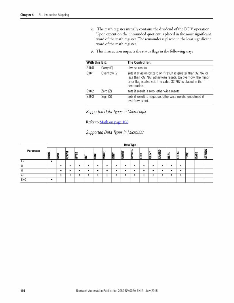
Chapter 4 RLL Instruction Mapping
2. The math register initially contains the dividend of the DDV operation. Upon execution the unrounded quotient is placed in the most significant word of the math register. The remainder is placed in the least significant word of the math register.
3. This instruction impacts the status flags in the following way:
Supported Data Types in MicroLogix
Refer to Math on page 106.
Supported Data Types in Micro800
With this Bit: The Controller:S:0/0 Carry (C) always resetsS:0/1 Overflow (V) sets if division by zero or if result is greater than 32,767 or
less than -32,768; otherwise resets. On overflow, the minor error flag is also set. The value 32,767 is placed in the destination.
S:0/2 Zero (Z) sets if result is zero, otherwise resets.S:0/3 Sign (S) sets if result is negative, otherwise resets; undefined if
overflow is set.
Parameter
Data Type
BOO
L
SIN
T
USI
NT
BYT
E
INT
UIN
T
WOR
D
DIN
T
UDI
NT
DW
ORD
LIN
T
ULI
NT
LWOR
D
REA
L
LREA
L
TIM
E
DAT
E
STRI
NG
EN •
i1 • • • • • • • • • • • • • •
i2 • • • • • • • • • • • • • •
o1 • • • • • • • • • • • • • •
ENO •
116 Rockwell Automation Publication 2080-RM002A-EN-E - July 2015
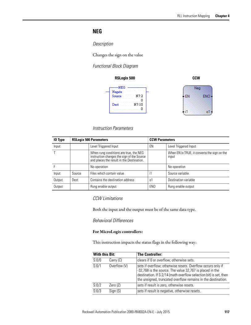
RLL Instruction Mapping Chapter 4
NEG
Description
Changes the sign on the value
Functional Block Diagram
Instruction Parameters
CCW Limitations
Both the input and the output must be of the same data type.
Behavioral Differences
For MicroLogix controllers:
This instruction impacts the status flags in the following way:
RSLogix 500 CCW
IO Type RSLogix 500 Parameters CCW Parameters
Input Level Triggered Input EN Level Triggered Input
T When rung conditions are true, the NEG instruction changes the sign of the Source and places the result in the Destination.
When EN is TRUE, it converts the sign on the input
F No operation No operation
Input Source Files which contain value i1 Source variable
Output Dest Contains the destination address o1 Destination variable
Output Rung enable output ENO Rung enable output
With this Bit: The Controller:S:0/0 Carry (C) clears if 0 or overflow; otherwise sets.S:0/1 Overflow (V) sets if overflow; otherwise resets. Overflow occurs only if
-32,768 is the source. The value 32,767 is placed in the destination. If S:2/14 (math overflow selection bit) is set, then the unsigned, truncated overflow remains in the destination.
S:0/2 Zero (Z) sets if result is zero, otherwise resets.S:0/3 Sign (S) sets if result is negative, otherwise resets.
Rockwell Automation Publication 2080-RM002A-EN-E - July 2015 117

Chapter 4 RLL Instruction Mapping
Supported Data Types in MicroLogix
Refer to Math on page 106.
Supported Data Types in Micro800
SQR
Description
Find the square root of a number
Functional Block Diagram
Instruction Parameters
Parameter
Data Type
BOO
L
SIN
T
USI
NT
BYT
E
INT
UIN
T
WOR
D
DIN
T
UDI
NT
DW
ORD
LIN
T
ULI
NT
LWOR
D
REA
L
LREA
L
TIM
E
DAT
E
STRI
NG
EN •
i1 • • • • • •
o1 • • • • • •
ENO •
RSLogix 500 CCW
IO Type RSLogix 500 Parameters CCW Parameters
Input Level Triggered Input EN Level Triggered Input
T When rung conditions are true, the SQR instruction calculates the square root and places the rounded result in the Destination.
When EN is TRUE, it calculates the square root of the input
F No operation No operation
Input Source Files which contain value or immediate value
i1 Source variable. Must be greater than equal to zero
Output Dest Contains the destination address SQRT Destination variable. The result is zero for negative input
Output Rung enable output ENO Rung enable output
118 Rockwell Automation Publication 2080-RM002A-EN-E - July 2015

RLL Instruction Mapping Chapter 4
CCW Limitations
1. Does not allow negative numbers as input.
2. Both the input and the output must be of the same data type.
Behavioral Differences
For MicroLogix controllers:
1. For MicroLogix 1000 processors constants are invalid for the source parameter.
2. This instruction calculates the square root of a negative number without overflow or faults. In applications where the source value may be negative, use a comparison instruction to evaluate the source value to determine if the destination may be invalid.
3. This instruction impacts the status flags in the following way:
Supported Data Types in MicroLogix
The MicroLogix supported data types SQR is as follows:
With this Bit: The Controller:S:0/0 Carry (C) sets if the source is negative; otherwise cleared.S:0/1 Overflow (V) always resets.S:0/2 Zero (Z) sets if destination value is zero.S:0/3 Sign (S) always resets.
SQR Instruction Valid Addressing Modes and File Types
Parameter
Data Files Function Files
CS -
Com
ms
IOS
- I/O
DLS
- D
ata
Log
Address Mode(1) Address Level
O I S B T, C
, R
N ST F L MG
, PD
RI/R
IX
PLS
RTC
HSC
PTO
X, P
WM
X
STI
EII
BHI
MM
I
LCD
Imm
edia
te
Dir
ect
Indi
rect
Bit
Wor
d
Long
Wor
d
Elem
ent
Source • • • • • • • • • • • • •
Destination • • • • • • • • • • • •
(1) See Important note about indirect addressing.
IMPORTANT You cannot use indirect addressing with: S, MG, PD, RTC, HSC, PTOX,
PWMX, STI, EII, BHI, MMI, CS, IOS, and DLS files.
Rockwell Automation Publication 2080-RM002A-EN-E - July 2015 119

Chapter 4 RLL Instruction Mapping
Supported Data Types in Micro800
Move and Logical The MicroLogix supported data types for AND, OR, XOR and NOT are as follows:
Supported Data Types in Micro800
Parameter
Data Type
BOO
L
SIN
T
USI
NT
BYT
E
INT
UIN
T
WO
RD
DIN
T
UD
INT
DWO
RD
LIN
T
ULI
NT
LWOR
D
REA
L
LREA
L
TIM
E
DATE
STRI
NG
EN •
IN •
SQRT •
ENO •
Logical Instructions Valid Addressing Modes and File Types
Parameter
Data Files Function Files(1)
CS -
Com
ms
IOS
- I/O
DLS-
Dat
a Lo
g
Address
Mode(2) Address Level
O I S B T, C
, R
N F ST L MG
, PD
RI/R
IX
PLS
RTC
HSC
PTO
X, P
WM
X
STI
EII
BHI
MM
I
LCD
Imm
edia
te
Dir
ect
Indi
rect
Bit
Wor
d
Long
Wor
d
Elem
ent
Source A • • • • • • • • • • • • • • • • • • • • • • • • •
Source B(3) • • • • • • • • • • • • • • • • • • • • • • • • •
Destination • • • • • • • • • • • • • • • • • •
(1) PTOX and PWMX files are valid for MicroLogix 1400 BXB or BXBA unit.
(2) See Important note about indirect addressing.
(3) Source B does not apply to the NOT instruction. The NOT instruction only has one source value.
IMPORTANT You cannot use indirect addressing with: S, MG, PD, RTC, HSC, PTOX,
PWMX, STI, EII, BHI, MMI, CS, IOS, and DLS files.
Parameter
Data Type
BOO
L
SIN
T
USI
NT
BYT
E
INT
UIN
T
WOR
D
DIN
T
UD
INT
DWO
RD
LIN
T
ULI
NT
LWOR
D
REA
L
LREA
L
TIM
E
DATE
STRI
NG
EN •
i1 • • • • • • • • • • • • • • • • • •
o1 • • • • • • • • • • • • • • • • • •
ENO •
120 Rockwell Automation Publication 2080-RM002A-EN-E - July 2015

RLL Instruction Mapping Chapter 4
MOV
Description
Move data from source to destination.
Functional Block Diagram
Instruction Parameters
CCW Limitations
Only supports same data types for both input and output.
RSLogix 500 CCW
IO Type RSLogix 500 Parameters CCW Parameters
Input Level Triggered Input EN Level Triggered Input
T When rung conditions preceding this instruction are true, the MOV instruction moves a copy of the source to the destination each scan. The original value remains intact and unchanged in its source location.
When EN is TRUE, copy the value of i1 to o1.
F No operation No operation
Input Source Immediate value or files which contain value
i1 Source variable
Output Dest Contains the destination address o1 Destination variable
Output Rung enable output ENO Rung enable output
Rockwell Automation Publication 2080-RM002A-EN-E - July 2015 121

Chapter 4 RLL Instruction Mapping
Behavioral Differences
For MicroLogix controllers:
1. The bit field variable can also be moved to an integer file. For example, B3:0 can be added to N7:0 where all the 16 bits in the B3:0 fields are used for moving.
2. This instruction impacts the status flags in the following way:
Supported Data Types in MicroLogix
Supported Data Types in Micro800
With this Bit: The Controller:S:0/0 Carry (C) always resets.S:0/1 Overflow (V) always resets.S:0/2 Zero (Z) sets if result is zero; otherwise resets.S:0/3 Sign (S) sets if result is negative (most significant bit is set);
otherwise resets.
Logical Instructions Valid Addressing Modes and File Types
Parameter
Data Files Function Files(1)
CS -
Com
ms
IOS
- I/O
DLS
- Dat
a Lo
g
Address Mode(2) Address Level
O I S B T, C
, R
N F ST L MG
, PD
RI/R
IX
PLS
RTC
HSC
PTO
X, P
WM
X
STI
EII
BHI
MM
I
LCD
Imm
edia
te
Dire
ct
Indi
rect
Bit
Wor
d
Long
Wor
d
Elem
ent
Source • • • • • • • • • • • • • • • • • • • • • • • • • • •
Destination • • • • • • • • • • • (3) (3) (3) (3) • • • •
(1) PTOX and PWMX files are valid for MicroLogix 1400 BXB or BXBA unit.
(2) See Important note about indirect addressing.
(3) Some elements can be written to. Consult the function file for details.
IMPORTANT You cannot use indirect addressing with: S, MG, PD, RTC, HSC, PTOX,
PWMX, STI, EII, BHI, MMI, CS, IOS, and DLS files.
Parameter
Data Type
BOO
L
SIN
T
USI
NT
BYT
E
INT
UIN
T
WOR
D
DIN
T
UDI
NT
DW
ORD
LIN
T
ULI
NT
LWOR
D
REA
L
LREA
L
TIM
E
DAT
E
STRI
NG
EN •
i1 • • • • • • • • • • • • • • • • • •
o1 • • • • • • • • • • • • • • • • • •
ENO •
122 Rockwell Automation Publication 2080-RM002A-EN-E - July 2015
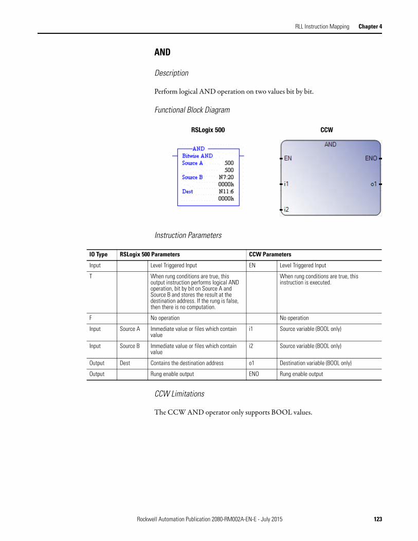
RLL Instruction Mapping Chapter 4
AND
Description
Perform logical AND operation on two values bit by bit.
Functional Block Diagram
Instruction Parameters
CCW Limitations
The CCW AND operator only supports BOOL values.
RSLogix 500 CCW
IO Type RSLogix 500 Parameters CCW Parameters
Input Level Triggered Input EN Level Triggered Input
T When rung conditions are true, this output instruction performs logical AND operation, bit by bit on Source A and Source B and stores the result at the destination address. If the rung is false, then there is no computation.
When rung conditions are true, this instruction is executed.
F No operation No operation
Input Source A Immediate value or files which contain value
i1 Source variable (BOOL only)
Input Source B Immediate value or files which contain value
i2 Source variable (BOOL only)
Output Dest Contains the destination address o1 Destination variable (BOOL only)
Output Rung enable output ENO Rung enable output
Rockwell Automation Publication 2080-RM002A-EN-E - July 2015 123

Chapter 4 RLL Instruction Mapping
Behavioral Differences
For MicroLogix controllers:
This instruction impacts the status flags in the following way:
Supported Data Types in MicroLogix
Refer to Move and Logical on page 120
Supported Data Types in Micro800
With this Bit: The Controller:S:0/0 Carry (C) always resets.S:0/1 Overflow (V) always resets.S:0/2 Zero (Z) sets if result is zero; otherwise resets.S:0/3 Sign (S) sets if most significant bit is set; otherwise resets.
Parameter
Data Type
BOOL
SIN
T
USIN
T
BYTE
INT
UIN
T
WO
RD
DIN
T
UD
INT
DW
ORD
LIN
T
ULI
NT
LWO
RD
REA
L
LREA
L
TIM
E
DATE
STRI
NG
EN •
i1 •
o1 •
ENO •
124 Rockwell Automation Publication 2080-RM002A-EN-E - July 2015
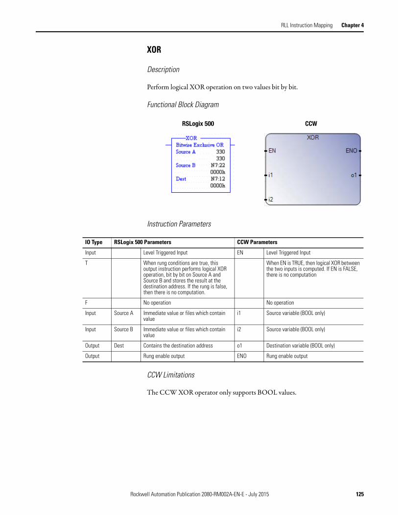
RLL Instruction Mapping Chapter 4
XOR
Description
Perform logical XOR operation on two values bit by bit.
Functional Block Diagram
Instruction Parameters
CCW Limitations
The CCW XOR operator only supports BOOL values.
RSLogix 500 CCW
IO Type RSLogix 500 Parameters CCW Parameters
Input Level Triggered Input EN Level Triggered Input
T When rung conditions are true, this output instruction performs logical XOR operation, bit by bit on Source A and Source B and stores the result at the destination address. If the rung is false, then there is no computation.
When EN is TRUE, then logical XOR between the two inputs is computed. If EN is FALSE, there is no computation
F No operation No operation
Input Source A Immediate value or files which contain value
i1 Source variable (BOOL only)
Input Source B Immediate value or files which contain value
i2 Source variable (BOOL only)
Output Dest Contains the destination address o1 Destination variable (BOOL only)
Output Rung enable output ENO Rung enable output
Rockwell Automation Publication 2080-RM002A-EN-E - July 2015 125

Chapter 4 RLL Instruction Mapping
Behavioral Differences
For MicroLogix controllers:
This instruction impacts the status flags in the following way:
Supported Data Types in MicroLogix
Refer to Move and Logical on page 120
Supported Data Types in Micro800
With this Bit: The Controller:S:0/0 Carry (C) always resets.S:0/1 Overflow (V) always resets.S:0/2 Zero (Z) sets if result is zero; otherwise resets.S:0/3 Sign (S) sets if result is negative (most significant bit is set);
otherwise resets.
Parameter
Data Type
BOOL
SIN
T
USI
NT
BYT
E
INT
UIN
T
WO
RD
DIN
T
UDIN
T
DW
ORD
LIN
T
ULI
NT
LWOR
D
REA
L
LREA
L
TIM
E
DATE
STRI
NG
EN •
i1 •
i2 •
o1 •
ENO •
126 Rockwell Automation Publication 2080-RM002A-EN-E - July 2015

RLL Instruction Mapping Chapter 4
OR
Description
Perform logical OR operation on two values bit by bit.
Functional Block Diagram
Instruction Parameters
CCW Limitations
The CCW OR operator only supports BOOL values.
RSLogix 500 CCW
IO Type RSLogix 500 Parameters CCW Parameters
Input Level Triggered Input EN Level Triggered Input
T When rung conditions are true, this output instruction performs logical OR operation, bit by bit on Source A and Source B and stores the result at the destination address. If the rung is false, then there is no computation.
When EN is TRUE, then logical OR between the two inputs is computed. If EN is FALSE, there is no computation
F No operation No operation
Input Source A Immediate value or files which contain value
i1 Source variable (BOOL only)
Input Source B Immediate value or files which contain value
i2 Source variable (BOOL only)
Output Dest Contains the destination address o1 Destination variable (BOOL only)
Output Rung enable output ENO Rung enable output
Rockwell Automation Publication 2080-RM002A-EN-E - July 2015 127

Chapter 4 RLL Instruction Mapping
Behavioral Differences
For MicroLogix controllers:
This instruction impacts the status flags in the following way:
Supported Data Types in MicroLogix
Refer to Move and Logical on page 120
Supported Data Types in Micro800
With this Bit: The Controller:S:0/0 Carry (C) always resets.S:0/1 Overflow (V) always resets.S:0/2 Zero (Z) sets if result is zero; otherwise resets.S:0/3 Sign (S) sets if result is negative (most significant bit is set);
otherwise resets.
Parameter
Data Type
BOOL
SIN
T
USI
NT
BYT
E
INT
UIN
T
WO
RD
DIN
T
UDIN
T
DW
ORD
LIN
T
ULI
NT
LWOR
D
REA
L
LREA
L
TIM
E
DATE
STRI
NG
EN •
i1 •
i2 •
o1 •
ENO •
128 Rockwell Automation Publication 2080-RM002A-EN-E - July 2015

RLL Instruction Mapping Chapter 4
NOT
Description
Perform logical NOT operation on two values bit by bit.
Functional Block Diagram
Instruction Parameters
CCW Limitations
The CCW NOT operator only supports BOOL values.
Behavioral Differences
For MicroLogix controllers:
This instruction impacts the status flags in the following way:
RSLogix 500 CCW
IO Type RSLogix 500 Parameters CCW Parameters
Input Level Triggered Input EN Level Triggered Input
T When rung conditions are true, this output instruction performs logical NOT operation, bit by bit on Source A and stores the result at the destination address. If the rung is false, then there is no computation.
When EN is TRUE, then logical NOT of the input is computed. If EN is FALSE, there is no computation
F No operation No operation
Input Source A Immediate value or files which contain value
i1 Source variable (BOOL only)
Output Dest Contains the destination address o1 Destination variable (BOOL only)
Output Rung enable output ENO Rung enable output
With this Bit: The Controller:S:0/0 Carry (C) always resets.S:0/1 Overflow (V) always resets.S:0/2 Zero (Z) sets if result is zero; otherwise resets.S:0/3 Sign (S) sets if result is negative (most significant bit is set);
otherwise resets.
Rockwell Automation Publication 2080-RM002A-EN-E - July 2015 129

Chapter 4 RLL Instruction Mapping
Supported Data Types in MicroLogix
Refer to Move and Logical on page 120
Supported Data Types in Micro800
Relay Type XIC
Description
Examine whether the bit field is ON based on the rung state.
Functional Block Diagram
Instruction Parameters
CCW Limitations
None
Behavioral Differences
None
Parameter
Data Type
BOO
L
SIN
T
USI
NT
BYT
E
INT
UIN
T
WOR
D
DIN
T
UDI
NT
DW
ORD
LIN
T
ULI
NT
LWOR
D
REA
L
LREA
L
TIM
E
DAT
E
STRI
NG
EN •
i1 •
o1 •
ENO •
RSLogix 500 CCW
Examine if Closed Direct Contact
IO Type RSLogix 500 Parameters CCW Parameters
Input Rung state is TRUE Rung state is TRUE
Output If the address bit is TRUE, then outputs on the rung are energized.
If the address bit is TRUE, then outputs on the rung are energized.
130 Rockwell Automation Publication 2080-RM002A-EN-E - July 2015

RLL Instruction Mapping Chapter 4
Supported Data Types in MicroLogix
The MicroLogix supported data types for XIC is as follows:
XIO
Description
Examine whether the bit field is OFF based on the rung state.
Functional Block Diagram
Instruction Parameters
CCW Limitations
None
XIC and XIO Instructions Valid Addressing Modes and File Types
Parameter
Data Files Function Files(1)
CS -
Com
ms
IOS
- I/O
DLS
- D
ata
Log
Address
Mode(2) Address Level
O I S B T, C
, R
N F ST L MG
, PD
RI/R
IX
PLS
RTC
HSC
PTO
X, P
WM
X
STI
EII
BHI
MM
I
LCD
Imm
edia
te
Dir
ect
Indi
rect
Bit
Wor
d
Long
Wor
d
Elem
ent
Operand Bit • • • • • • • • • • • • • • • • • • • • • •
(1) PTOX and PWMX files are only for use with MicroLogix 1400 BXB or BXBA unit.
(2) See Important note about indirect addressing.
IMPORTANT You cannot use indirect addressing with: S, MG, PD, RTC, HSC, PTOX,
PWMX, STI, EII, BHI, MMI, CS, IOS, and DLS files.
RSLogix 500 CCW
Examine if Open Reverse Contact
IO Type RSLogix 500 Parameters CCW Parameters
Input Rung state is TRUE Rung state is TRUE
Output If the address bit is TRUE, then outputs on the rung are de-energized.
If the address bit is TRUE, then outputs on the rung are de-energized.
Rockwell Automation Publication 2080-RM002A-EN-E - July 2015 131
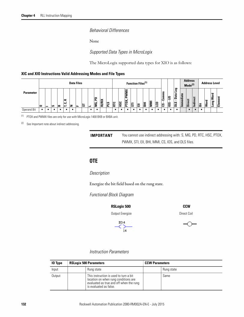
Chapter 4 RLL Instruction Mapping
Behavioral Differences
None
Supported Data Types in MicroLogix
The MicroLogix supported data types for XIO is as follows:
OTE
Description
Energize the bit field based on the rung state.
Functional Block Diagram
Instruction Parameters
XIC and XIO Instructions Valid Addressing Modes and File Types
Parameter
Data Files Function Files(1)
CS -
Com
ms
IOS
- I/O
DLS
- D
ata
Log
Address
Mode(2) Address Level
O I S B T, C
, R
N F ST L MG
, PD
RI/R
IX
PLS
RTC
HSC
PTO
X, P
WM
X
STI
EII
BHI
MM
I
LCD
Imm
edia
te
Dir
ect
Indi
rect
Bit
Wor
d
Long
Wor
d
Elem
ent
Operand Bit • • • • • • • • • • • • • • • • • • • • • •
(1) PTOX and PWMX files are only for use with MicroLogix 1400 BXB or BXBA unit.
(2) See Important note about indirect addressing.
IMPORTANT You cannot use indirect addressing with: S, MG, PD, RTC, HSC, PTOX,
PWMX, STI, EII, BHI, MMI, CS, IOS, and DLS files.
RSLogix 500 CCW
Output Energize Direct Coil
IO Type RSLogix 500 Parameters CCW Parameters
Input Rung state Rung state
Output This instruction is used to turn a bit location on when rung conditions are evaluated as true and off when the rung is evaluated as false.
Same
132 Rockwell Automation Publication 2080-RM002A-EN-E - July 2015

RLL Instruction Mapping Chapter 4
CCW Limitations
None
Behavioral Differences
For MicroLogix controllers:
The OTE is reset when programmed within an inactive or false Master Control Reset (MCR) zone.
Supported Data Types in MicroLogix
The MicroLogix supported data types for OTE is as follows:
OTE Instruction Valid Addressing Modes and File Types
Parameter
Data Files Function Files(1)
CS -
Com
ms
IOS
- I/O
DLS
- D
ata
Log
Address
Mode(2) Address Level
O I S B T, C
, R
N F ST L MG
, PD
RI/R
IX
PLS
RTC
HSC
PTO
X, P
WM
X
STI
EII
BHI
MM
I
LCD
Imm
edia
te
Dir
ect
Indi
rect
Bit
Wor
d
Long
Wor
d
Elem
ent
Destination Bit • • • • • • • • • • • • • • • • •
(1) PTOX and PWMX files are only for use with MicroLogix 1400 BXB or BXBA unit.
(2) See Important note about indirect addressing.
IMPORTANT You cannot use indirect addressing with: S, MG, PD, RTC, HSC, PTOX,
PWMX, STI, EII, BHI, MMI, CS, IOS, and DLS files.
Rockwell Automation Publication 2080-RM002A-EN-E - July 2015 133

Chapter 4 RLL Instruction Mapping
OTL
Description
Latch (Set) the bit field.
Functional Block Diagram
Instruction Parameters
CCW Limitations
None
Behavioral Differences
For MicroLogix controllers:
1. In the event of a power loss, any OTL controlled output device will energize with the return of power if the OTL bit was set when power was lost.
2. If an error condition occurs that halts processing, the physical output will be turned off. But once the error condition is cleared the controller will resume operation with the OTL in the state determined by its data table value.
RSLogix 500 CCW
Output Latch Set Coil
IO Type RSLogix 500 Parameters CCW Parameters
Input Rung state Rung state
Output When the rung conditions are TRUE this bit is set or "latched" on. Once a bit has been set "on" (1 in the memory) it will remain "on" even if the rung condition goes false. The bit must be reset with an OTU instruction.
When the rung conditions are TRUE this bit is set or "latched" on. Once a bit has been set "on" (1 in the memory) it will remain "on" even if the rung condition goes false. The bit must be reset with a Reset Coil instruction.
134 Rockwell Automation Publication 2080-RM002A-EN-E - July 2015
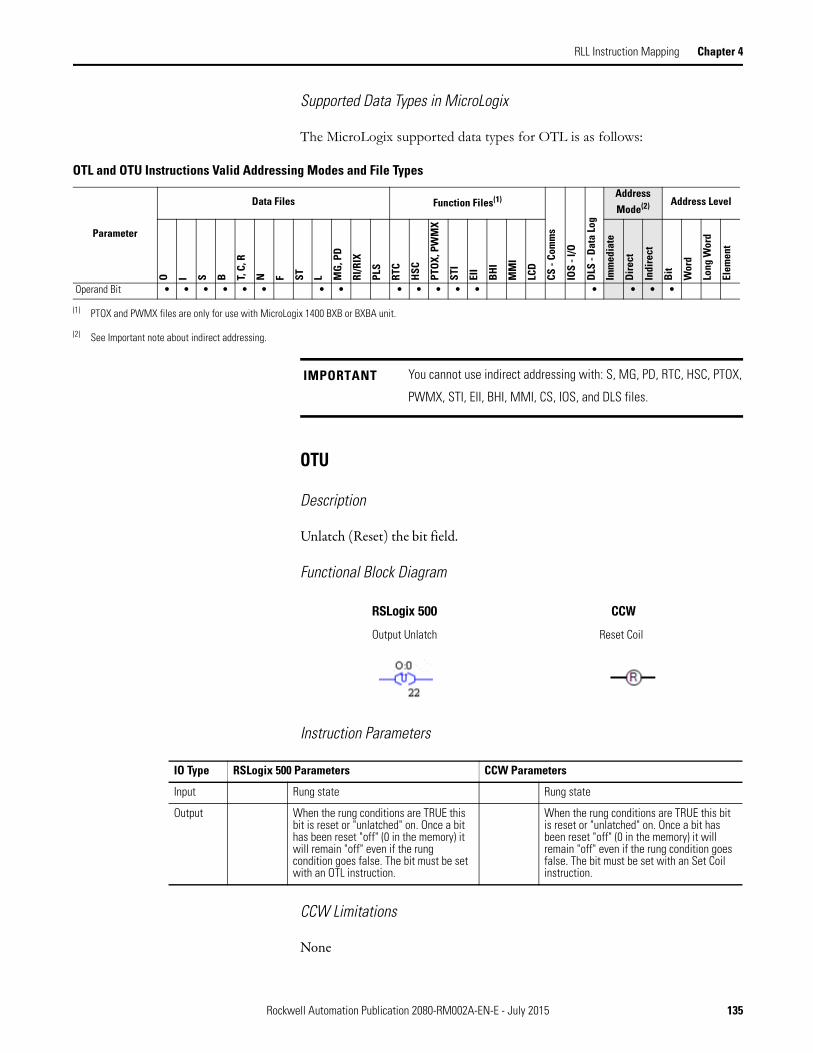
RLL Instruction Mapping Chapter 4
Supported Data Types in MicroLogix
The MicroLogix supported data types for OTL is as follows:
OTU
Description
Unlatch (Reset) the bit field.
Functional Block Diagram
Instruction Parameters
CCW Limitations
None
OTL and OTU Instructions Valid Addressing Modes and File Types
Parameter
Data Files Function Files(1)
CS -
Com
ms
IOS
- I/O
DLS
- D
ata
Log
Address Mode(2) Address Level
O I S B T, C
, R
N F ST L MG
, PD
RI/R
IX
PLS
RTC
HSC
PTO
X, P
WM
X
STI
EII
BHI
MM
I
LCD
Imm
edia
te
Dire
ct
Indi
rect
Bit
Wor
d
Long
Wor
d
Elem
ent
Operand Bit • • • • • • • • • • • • • • • • •
(1) PTOX and PWMX files are only for use with MicroLogix 1400 BXB or BXBA unit.
(2) See Important note about indirect addressing.
IMPORTANT You cannot use indirect addressing with: S, MG, PD, RTC, HSC, PTOX,
PWMX, STI, EII, BHI, MMI, CS, IOS, and DLS files.
RSLogix 500 CCW
Output Unlatch Reset Coil
IO Type RSLogix 500 Parameters CCW Parameters
Input Rung state Rung state
Output When the rung conditions are TRUE this bit is reset or "unlatched" on. Once a bit has been reset "off" (0 in the memory) it will remain "off" even if the rung condition goes false. The bit must be set with an OTL instruction.
When the rung conditions are TRUE this bit is reset or "unlatched" on. Once a bit has been reset "off" (0 in the memory) it will remain "off" even if the rung condition goes false. The bit must be set with an Set Coil instruction.
Rockwell Automation Publication 2080-RM002A-EN-E - July 2015 135

Chapter 4 RLL Instruction Mapping
Behavioral Differences
For MicroLogix controllers:
1. If an error condition that halts processing occurs, the physical output will be turned off. But once the error condition is cleared the controller will resume operation with the OTU in the state determined by its data table value.
2. In the event of a power loss, any OTL controlled output device will energize with the return of power if the OTL bit was set when power was lost.
Supported Data Types in MicroLogix
The MicroLogix supported data types for OTU is as follows:
OTL and OTU Instructions Valid Addressing Modes and File Types.
Parameter
Data Files Function Files(1)
CS -
Com
ms
IOS
- I/O
DLS
- Da
ta L
og
Address Mode(2) Address Level
O I S B T, C
, R
N F ST L MG
, PD
RI/R
IX
PLS
RTC
HSC
PTO
X, P
WM
X
STI
EII
BHI
MM
I
LCD
Imm
edia
te
Dir
ect
Indi
rect
Bit
Wor
d
Long
Wor
d
Elem
ent
Operand Bit • • • • • • • • • • • • • • • • •
(1) PTOX and PWMX files are only for use with MicroLogix 1400 BXB or BXBA unit.
(2) See Important note about indirect addressing.
IMPORTANT You cannot use indirect addressing with: S, MG, PD, RTC, HSC, PTOX,
PWMX, STI, EII, BHI, MMI, CS, IOS, and DLS files.
136 Rockwell Automation Publication 2080-RM002A-EN-E - July 2015
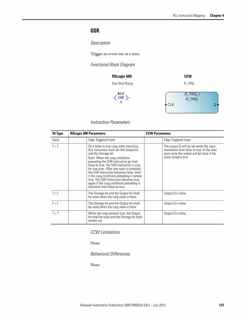
RLL Instruction Mapping Chapter 4
OSR
Description
Trigger an event one at a time.
Functional Block Diagram
Instruction Parameters
CCW Limitations
None
Behavioral Differences
None
RSLogix 500 CCW
One Shot Rising R_TRIG
IO Type RSLogix 500 Parameters CCW Parameters
Input Edge Triggered Input Edge Triggered Input
F > T On a false to true rung state transition, this instruction shall set the Output bit and the Storage bit.Note: When the rung conditions preceding the OSR instruction go from false-to-true, the OSR instruction is true for one scan. After one scan is complete, the OSR instruction becomes false, even if the rung conditions preceding it remain true. The OSR instruction becomes true again if the rung conditions preceding it transition from false-to-true.
The output Q will be set when the input transitions from false to true. In the next scan cycle the output will be false if the clock remains true.
T > F The Storage bit and the Output bit shall be reset when the rung state is false.
Output Q is false
F > F The Storage bit and the Output bit shall be reset when the rung state is false.
Output Q is false
T > T While the rung remains true, the Output bit shall be reset and the Storage bit shall remain set
Output Q is false
Rockwell Automation Publication 2080-RM002A-EN-E - July 2015 137

Chapter 4 RLL Instruction Mapping
Supported Data Types in MicroLogix
The MicroLogix supported data types for OSR is as follows:
Supported Data Types in Micro800
OSR and OSF Instructions Valid Addressing Modes and File Types
Parameter
Data Files Function Files
CS -
Com
ms
IOS
- I/O
DLS
- Da
ta L
og
Address Mode
Address Level
O I S B T, C
, R
N F ST L MG
, PD
RI/R
IX
PLS
RTC
HSC
PTO
X, P
WM
X
STI
EII
BHI
MM
I
LCD
Imm
edia
te
Dir
ect
Indi
rect
Bit
Wor
d
Long
Wor
d
Elem
ent
Storage Bit • • • •
Output Bit • • • • • • • •
Parameter
Data Type
BOOL
SIN
T
USI
NT
BYT
E
INT
UIN
T
WO
RD
DIN
T
UD
INT
DW
ORD
LIN
T
ULI
NT
LWOR
D
REA
L
LREA
L
TIM
E
DATE
STRI
NG
EN •
CLK •
Q •
ENO •
138 Rockwell Automation Publication 2080-RM002A-EN-E - July 2015

RLL Instruction Mapping Chapter 4
Timer and Counter The MicroLogix supported data types for TON, TOF and RTO are as follows:
The MicroLogix supported data types for CTD and CTU are as follows:
Timer Instructions Valid Addressing Modes and File Types
Parameter
Data Files(1) Function Files
CS -
Com
ms
IOS
- I/O
DLS
- Da
ta L
og
Address Mode
Address Level
O I S B T, C
, R
N F ST L MG
, PD
RI/R
IX
PLS
RTC
HSC
PTO
X, P
WM
X
STI
EII
BHI
MM
I
LCD
Imm
edia
te
Dir
ect
Indi
rect
Bit
Wor
d
Long
Wor
d
Elem
ent
Timer • • •
Time Base • •
Preset • •
Accumulator • •
(1) Valid for Timer Files only.
CTD and CTU Instructions Valid Addressing Modes and File Types
Parameter
Data Files(1) Function Files
CS -
Com
ms
IOS
- I/O
DLS
- D
ata
Log
Address Mode
Address Level
O I S B T, C
, R
N F ST L MG
, PD
RI/R
IX
PLS
RTC
HSC
PTO
X, P
WM
X
STI
EII
BHI
MM
I
LCD
Imm
edia
te
Dire
ct
Indi
rect
Bit
Wor
d
Long
Wor
d
Elem
ent
Counter • • •
Preset • •
Accumulator • •
(1) Valid for Counter Files only.
Rockwell Automation Publication 2080-RM002A-EN-E - July 2015 139

Chapter 4 RLL Instruction Mapping
CTD
Description
Count down from a certain value one by one.
Functional Block Diagram
Instruction Parameters
RSLogix 500 CCW
IO Type RSLogix 500 Parameters CCW Parameters
Input Edge Triggered Input CD Edge Triggered Input
F > T This instruction counts down on false to true rung transition
Down counts when CD is a rising edge
T > F Whenever the rung state is false, the counter shall not count and CD shall be reset. If either of the OV or UN bit is set, the DN bit shall remain in its last state. If the OV and UN bits are clear, the DN bit is reset if Accumulator < Preset, otherwise it is set.
Updates the underflow flag (Q)
F > F Same as T > F state Updates the underflow flag (Q)
T > T Whenever the rung state is true, the counter shall not count and CU shall remain set.
Updates the underflow flag (Q)
Input Preset Programmed initial Value (16 bit signed integer)
PV Programmed initial value (32 bit signed integer)
Input LOAD CV = PV when LOAD is TRUE.
Output Counter CD (Enable)
This bit is set to TRUE when the rung is TRUE. It is cleared when rung is false or RES instruction is used.
Not supported
Output Counter UV (Underflow)
When an underflow occurs from -32768 to 32767, this bit is set to TRUE. The counter continues to down count from 32767.
Q It is set to TRUE when the count value reaches zero. The down counter freezes at zero.
140 Rockwell Automation Publication 2080-RM002A-EN-E - July 2015
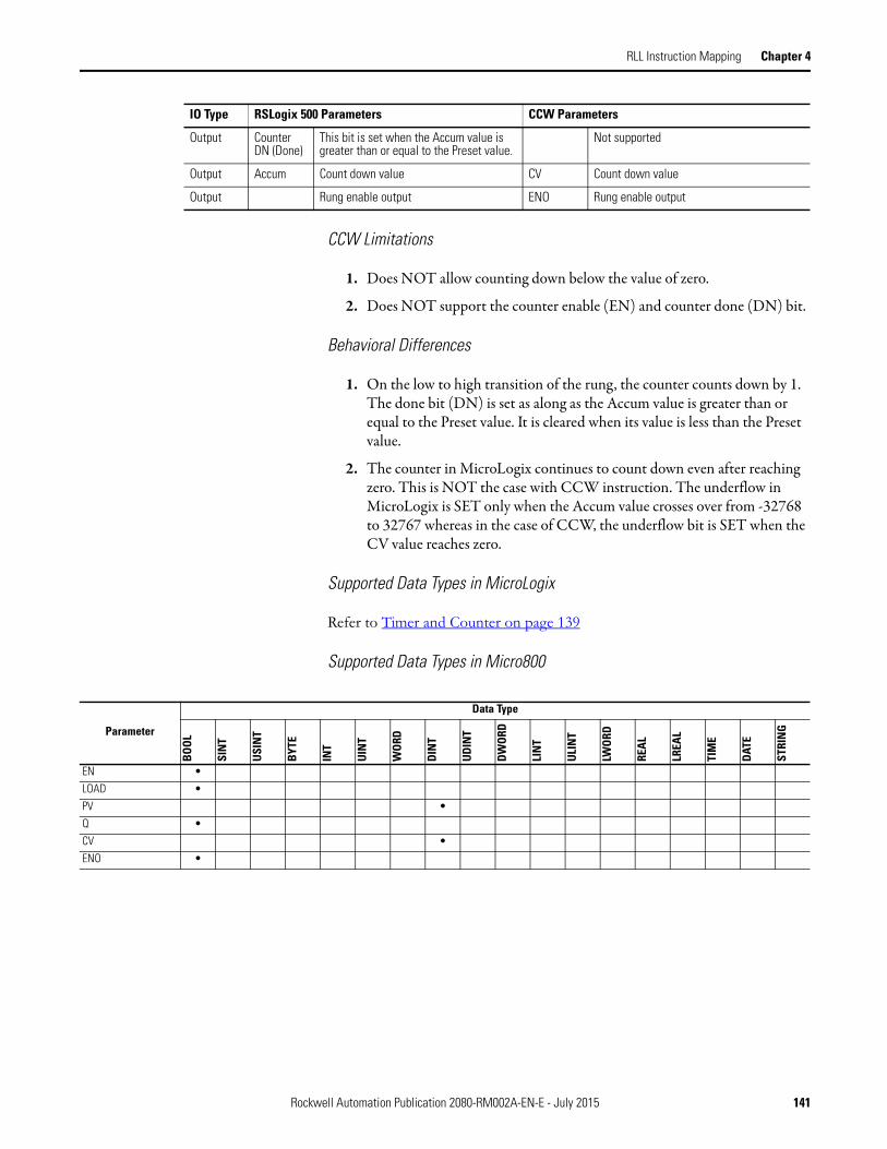
RLL Instruction Mapping Chapter 4
CCW Limitations
1. Does NOT allow counting down below the value of zero.
2. Does NOT support the counter enable (EN) and counter done (DN) bit.
Behavioral Differences
1. On the low to high transition of the rung, the counter counts down by 1. The done bit (DN) is set as along as the Accum value is greater than or equal to the Preset value. It is cleared when its value is less than the Preset value.
2. The counter in MicroLogix continues to count down even after reaching zero. This is NOT the case with CCW instruction. The underflow in MicroLogix is SET only when the Accum value crosses over from -32768 to 32767 whereas in the case of CCW, the underflow bit is SET when the CV value reaches zero.
Supported Data Types in MicroLogix
Refer to Timer and Counter on page 139
Supported Data Types in Micro800
Output Counter DN (Done)
This bit is set when the Accum value is greater than or equal to the Preset value.
Not supported
Output Accum Count down value CV Count down value
Output Rung enable output ENO Rung enable output
IO Type RSLogix 500 Parameters CCW Parameters
Parameter
Data Type
BOOL
SIN
T
USI
NT
BYT
E
INT
UIN
T
WO
RD
DIN
T
UD
INT
DW
ORD
LIN
T
ULIN
T
LWO
RD
REA
L
LREA
L
TIM
E
DATE
STRI
NG
EN •
LOAD •
PV •
Q •
CV •
ENO •
Rockwell Automation Publication 2080-RM002A-EN-E - July 2015 141

Chapter 4 RLL Instruction Mapping
CTU
Description
This instruction counts up from a certain value one by one.
Functional Block Diagram
Instruction Parameters
RSLogix 500 CCW
IO Type RSLogix 500 Parameters CCW Parameters
Input Edge Triggered Input CU Edge Triggered Input
F > T This instruction counts up on false to true rung transition
It counts up when CU is a rising edge
T > F Whenever the rung state is false, the counter shall not count and the CU bit shall be reset. If either of the OV or UN bits is set, the DN bit shall remain in its last state. If the OV and UN bits are clear, the DN bit is reset if Accumulator < Preset, otherwise it is set.
Updates the overflow flag (Q)
F > F Same as T > F state Updates the overflow flag (Q)
T > T Whenever the rung state is true, the counter shall not count and CU shall remain set.
Updates the overflow flag (Q)
Input Preset Programmed initial value (16 bit signed integer)
PV Programmed initial value (32 bit signed integer)
Input RESET When RESET is TRUE, it will initialize the CV value to zero.
Output Counter CU (Enable)
This bit is set to TRUE when the rung is TRUE. It is cleared when rung is false or RES instruction is used.
Not supported
Output Counter DN (Done)
It is set to TRUE when the Accum value is greater than or equal to Preset value.
Q It is set to TRUE when the count value is greater than or equal to the value of PV. The counter stops counting up when it reaches the value of PV.
142 Rockwell Automation Publication 2080-RM002A-EN-E - July 2015

RLL Instruction Mapping Chapter 4
CCW Limitations
None
Behavioral Differences
In CCW, the counter will count upwards until it reaches the limit of CV whereas in case of RSLogix, the counter will continue to up count.
Supported Data Types in MicroLogix
Refer to Timer and Counter on page 139
Supported Data Types in Micro800
Output Counter OV (Overflow)
When an overflow occurs from 32767 to -32768, this bit is set to TRUE. The counter continues to up from -32768.
Not supported
Output Accum 16 bit accumulated count. It can be reset to zero by using the RES instruction.
CV 32 bit accumulated value. It is reset by setting the RESET to TRUE.
Output Rung enable output ENO Rung enable output
IO Type RSLogix 500 Parameters CCW Parameters
Parameter
Data Type
BOO
L
SIN
T
USI
NT
BYT
E
INT
UIN
T
WOR
D
DIN
T
UDI
NT
DW
ORD
LIN
T
ULI
NT
LWOR
D
REA
L
LREA
L
TIM
E
DAT
E
STRI
NG
EN •
CU •
RESET •
PV •
Q •
CV •
ENO •
Rockwell Automation Publication 2080-RM002A-EN-E - July 2015 143

Chapter 4 RLL Instruction Mapping
TON
Description
This instruction is used to turn an output on or off after the timer has been on for a preset time interval.
Functional Block Diagram
Instruction Parameters
RSLogix 500 CCW
IO Type RSLogix 500 Parameters CCW Parameters
Input Edge Triggered Input IN Edge Triggered Input
F > T When the rung transitions from false to true, the error checks specified under Faults Generated shall be performed. If there are no errors, the timer shall be updated as follows.- If the DN bit is set, the EN bit shall be set and the TT bit shall be reset. Nothing else is updated.- If the DN bit is reset, the timer shall be initialized to begin counting Timebase intervals starting from the time the rung state transition is detected. The EN and TT bits shall be set.
Starts increasing the internal timer on the rising edge under the following conditions:- If the IN is TRUE and the Q flag is FALSE
T > F Whenever the rung state is false, the Accumulator shall be set to zero and the EN, TT, and DN bits shall be reset.
Stops and resets the internal timer on the falling edge.
F > F Same as T > F Same as T > F
T > T While the rung state remains true, the error checks specified under Faults Generated shall be performed. If there are no errors, the timer shall be updated as follows.- If the DN bit is set, the TT bit shall be reset. Nothing else is updated.- If the DN bit is reset, the Accumulator shall be updated according to the number of Timebase intervals that have passed since the last time the timer was updated.- If Accumulator < Preset, the TT bit shall be set.- If Accumulator Preset, the DN bit shall be set and the TT bit shall be reset.
Same as F > T case.
144 Rockwell Automation Publication 2080-RM002A-EN-E - July 2015

RLL Instruction Mapping Chapter 4
CCW Limitations
None
Behavioral Differences
For MicroLogix controllers:
1. If power is lost while a TON is timing but has not reached its preset value, the EN, and TT bits remain set, and the accumulated value (ACCUM) remains the same. This is also true if the processor changes from the REM Run or REM Test mode to the REM Program mode.
2. If either the Accumulator or the Preset is negative when the TON instruction is executed on a true rung, a Major Fault (0034) is generated.
Status Bits
Input Preset Programmed initial value (16 bit unsigned integer)
PT Programmed initial value (Time data type)
Input Time Base 1ms, 10ms or 1s Supported
Output Timer EN (Enable)
This bit is set to TRUE when the rung is TRUE. It is cleared when rung is false.
Not supported
Output Timer DN (Done)
It is set to TRUE when the Accum value is greater than or equal to Preset value.
Q It is set to TRUE when the count value is equal to the value of PT. The counter stops counting up when it reaches the value of PT.
Output Timer TT (Timing)
It is set when rung conditions are TRUE and the accumulated value is less than the preset value and cleared when the rung state is FALSE or when done bit is set.
Not supported
Output Accum 16 bit accumulated count. It can be reset to zero when the rung conditions are FALSE.
ET In Time data type format
Output Rung enable output ENO Rung enable output
IO Type RSLogix 500 Parameters CCW Parameters
This Bit Is Set When And Remains Set Until One of the Following
Timer Done Bit DN (bit 13) accumulated value is equal to or greater than the preset value
rung conditions go false
Timer Enable Bit EN (bit 14) rung conditions are true rung conditions go falseTimer Timing Bit TT (bit 15) rung conditions are true and
the accumulated value is less than the preset value
rung conditions go false or when the done bit is set
Rockwell Automation Publication 2080-RM002A-EN-E - July 2015 145
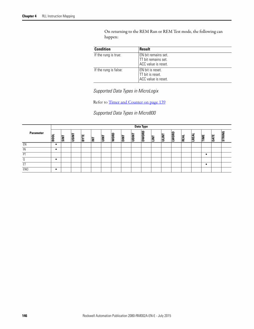
Chapter 4 RLL Instruction Mapping
On returning to the REM Run or REM Test mode, the following can happen:
Supported Data Types in MicroLogix
Refer to Timer and Counter on page 139
Supported Data Types in Micro800
Condition ResultIf the rung is true: EN bit remains set.
TT bit remains set.ACC value is reset.
If the rung is false: EN bit is reset.TT bit is reset.ACC value is reset.
Parameter
Data Type
BOOL
SIN
T
USI
NT
BYT
E
INT
UIN
T
WO
RD
DIN
T
UDIN
T
DW
ORD
LIN
T
ULI
NT
LWOR
D
REA
L
LREA
L
TIM
E
DATE
STRI
NG
EN •
IN •
PT •
Q •
ET •
ENO •
146 Rockwell Automation Publication 2080-RM002A-EN-E - July 2015
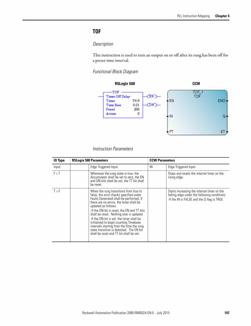
RLL Instruction Mapping Chapter 4
TOF
Description
This instruction is used to turn an output on or off after its rung has been off for a preset time interval.
Functional Block Diagram
Instruction Parameters
RSLogix 500 CCW
IO Type RSLogix 500 Parameters CCW Parameters
Input Edge Triggered Input IN Edge Triggered Input
F > T Whenever the rung state is true, the Accumulator shall be set to zero, the EN and DN bits shall be set, the TT bit shall be reset.
Stops and resets the internal timer on the rising edge.
T > F When the rung transitions from true to false, the error checks specified under Faults Generated shall be performed. If there are no errors, the timer shall be updated as follows.-If the DN bit is reset, the EN and TT bits shall be reset. Nothing else is updated.-If the DN bit is set, the timer shall be initialized to begin counting Timebase intervals starting from the time the rung state transition is detected. The EN bit shall be reset and TT bit shall be set.
Starts increasing the internal timer on the falling edge under the following conditions:-If the IN is FALSE and the Q flag is TRUE
Rockwell Automation Publication 2080-RM002A-EN-E - July 2015 147

Chapter 4 RLL Instruction Mapping
CCW Limitations
None
F > F While the rung state remains false, the error checks specified under Faults Generated shall be performed. If there are no errors, the timer shall be updated as follows.-If the DN bit is reset, the TT bit shall be reset. Nothing else is updated.-If the DN bit is set, the Accumulator shall be updated according to the number of Timebase intervals that have passed since the last time the timer was updated.-If Accumulator < Preset, the TT bit shall be set.-If Accumulator Preset, the DN and TT bits shall be reset.
Same as T > F. case.
T > T Whenever the rung state is true, the Accumulator shall be set to zero, the EN and DN bits shall be set, the TT bit shall be reset.
Sets the overflow flag (Q).
Input Preset Programmed initial value (16 bit unsigned integer)
PT Programmed initial value (Time data type)
Input Time Base 1ms, 10ms or 1s Supported
Output Timer EN (Enable)
This bit is set to TRUE when the rung is TRUE. It is cleared when rung is false.
Not supported
Output Timer DN (Done)
It is set to FALSE when the Accum value is greater than or equal to Preset value.
Q It is set to FALSE when the ET value is equal to the value of PT. The internal timer stops when it reaches the value of PT.
Output Timer TT (Timing)
It is set when rung conditions are FALSE or the accumulated value is less than the Preset value. It is cleared once the rung is TRUE or done bit is reset.
Not supported
Output Accum 16 bit accumulated count. It can be reset to zero when the rung conditions are TRUE.
ET In Time data type format
Output Rung enable output ENO Rung enable output
IO Type RSLogix 500 Parameters CCW Parameters
148 Rockwell Automation Publication 2080-RM002A-EN-E - July 2015

RLL Instruction Mapping Chapter 4
Behavioral Differences
For MicroLogix controllers:
When controller operation changes from REM Run or REM Test mode to REM Program mode or if user power is lost while a TOF is timing but has not reached its preset value, the EN, TT, and DN bits remain set, and the accumulated value (ACCUM) remains the same.
On returning to the REM Run or REM Test mode, the following can happen:
Supported Data Types in MicroLogix
Refer to Timer and Counter on page 139
Supported Data Types in Micro800
Condition ResultIf the rung is true: TT bit is reset
DN bit remains setEN bit is setACC value is reset.
If the rung is false: TT bit is resetDN bit is resetEN bit is resetACC value is set equal to the preset value
Parameter
Data Type
BOO
L
SIN
T
USI
NT
BYT
E
INT
UIN
T
WOR
D
DIN
T
UDI
NT
DW
ORD
LIN
T
ULI
NT
LWOR
D
REA
L
LREA
L
TIM
E
DAT
E
STRI
NG
EN •
IN •
PT •
Q •
ET •
ENO •
Rockwell Automation Publication 2080-RM002A-EN-E - July 2015 149
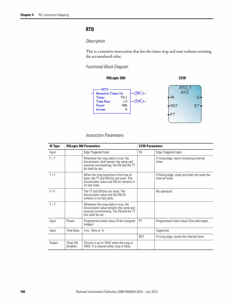
Chapter 4 RLL Instruction Mapping
RTO
Description
This is a retentive instruction that lets the timer stop and start without resetting the accumulated value.
Functional Block Diagram
Instruction Parameters
RSLogix 500 CCW
IO Type RSLogix 500 Parameters CCW Parameters
Input Edge Triggered Input IN Edge Triggered Input
F > T Whenever the rung state is true, the Accumulator shall remain the same and resumes incrementing, the EN and the TT bit shall be set.
If rising edge, starts increasing internal timer.
T > F When the rung transitions from true to false, the TT and EN bits are reset. The Accumulator value and DN bit remains in its last state.
If falling edge, stops and does not reset the internal timer.
F > F The TT and EN bits are reset. The Accumulator value and the DN bit remains in its last state.
No operation
T > T Whenever the rung state is true, the Accumulator value remains the same and resumes incrementing. The EN and the TT bits shall be set.
Input Preset Programmed initial value (16 bit unsigned integer)
PT Programmed initial value (Time data type)
Input Time Base 1ms, 10ms or 1s Supported
RST If rising edge, resets the internal timer.
Output Timer EN (Enable)
This bit is set to TRUE when the rung is TRUE. It is cleared when rung is false.
150 Rockwell Automation Publication 2080-RM002A-EN-E - July 2015
RLL Instruction Mapping Chapter 4
CCW Limitations
If using a Micro810 or Micro820 controller, the RTO internal timer does not persist through a power cycle by default. To persist the internal timer, set the Retained configuration parameter to true.
If using a Micro830 or Micro850 controller, the RTO internal timer will persist through a power cycle.
Behavioral Differences
For MicroLogix controllers:
When the processor changes from the REM Run or REM Test mode to the REM Program or REM Fault mode, or user power is lost while the timer is timing but not yet at the preset value, the following occurs:
• Timer Enable (EN) bit remains set.• Timer Timing (TT) bit remains set.• Accumulated value (ACC) remains the same.
On returning to the REM Run or REM Test mode, the following can happen:
Supported Data Types in MicroLogix
Refer to Timer and Counter on page 139
Output Timer DN (Done)
It is set to TRUE when the Accum value is equal to or greater than the Preset value.
Q If TRUE, programmed time is elapsed.
Output Timer TT (Timing)
It is set when rung conditions are TRUE or the accumulated value is less than the Preset value. It is cleared once the rung is FALSE or done bit is set.
Not supported
Output Accum 16 bit accumulated count. It can be reset to zero when the rung conditions are TRUE.
ET Elapsed time. Possible values range from 0ms to 1193h2m47s294ms.
IO Type RSLogix 500 Parameters CCW Parameters
Condition ResultIf the rung is true: TT bit remains set
EN bit remains setACC value remains the same and resumes incrementing.
If the rung is false: TT bit is resetDN bit remains in its last state.EN bit is resetACC value remains in its last state.
Rockwell Automation Publication 2080-RM002A-EN-E - July 2015 151

Chapter 4 RLL Instruction Mapping
Supported Data Types in Micro800
High Speed Counter
Description
The HSC instruction counts high-speed pulses from a high-speed input with a specified maximum pulse rate.
Functional Block Diagram
Parameter
Data Type
BOO
L
SIN
T
USI
NT
BYT
E
INT
UIN
T
WO
RD
DIN
T
UD
INT
DWO
RD
LIN
T
ULI
NT
LWOR
D
REA
L
LREA
L
TIM
E
DATE
STRI
NG
EN •
IN •
RST •
PT •
Q •
ET •
ENO •
RSLogix 500 CCW
152 Rockwell Automation Publication 2080-RM002A-EN-E - July 2015

RLL Instruction Mapping Chapter 4
Instruction Parameters
CCW Limitations
None
Behavioral Differences
For MicroLogix controllers:
When the high-speed counter is enabled, data table counter C5:0 is used by the ladder program for monitoring the high-speed counter accumulator and status.
Counter Data File Elements (C5:0)
Counter preset and accumulated values are stored as signed integers.
IO Type RSLogix 500 Parameters CCW Parameters
Input Level Triggered Input Enable Level Triggered Input
T Whenever the rung state is true, the Accumulator shall be set to zero, the EN and DN bits shall be set, the TT bit shall be reset.
Function block enable. When Enable = TRUE, execute the HSC operation specified in the HSC command parameter.
F The high-speed counter is disabled from counting
When Enable = FALSE, no HSC commands are issued.
Input Type Select from Up counters or Bidirectional counters. Up Counters clear the accumulator values and reload the preset values when the previous preset is reached. In Bidirectional Counters the accumulator and preset values are not changed by the high-speed counter when the presets are reached.
HscCmd Issues commands to the HSC.
Input Counter Always C5:0 HscAppData HSC application configuration, which is usually only needed once.
Input Preset The accumulated value that triggers an action such as updating outputs or generating a high-speed counter interrupt.
HscStsInfo HSC application configuration, which is usually only needed once.
Input Accum The number of accumulated counts. PlsData Programmable Limit Switch (PLS) data structure.
Output CU Count Up Enabled ENO Rung enable output
Output CD Count Down Enabled Sts HSC execution status.
Output DN High Preset Reached
15 14 13 12 11 10 09 08 07 06 05 04 03 02 01 00
Word 0 CU CD DN OV UN UA HP LP IV IN IH IL PE LS IE <- Status Word
Word 1 Preset Value
Word 2 Accumulator Value
Rockwell Automation Publication 2080-RM002A-EN-E - July 2015 153

Chapter 4 RLL Instruction Mapping
For Micro800 controllers:
The high-speed counter accumulator and status are found under the HscSTSInfo parameters.
Parameter Data type HSC mode
User program access
Description
CountEnable BOOL 0...9 read only Counting enabled.
ErrorDetected BOOL 0...9 read/write Non-zero means error detected.
CountUpFlag BOOL 0...9 read only Count up flag.
CountDwnFlag BOOL 2...9 read only Count down flag.
Mode1Done BOOL 0 or 1 read/write HSC is Mode 1A or Mode 1B; accumulator counts up to the HP value.
OVF BOOL 0...9 read/write Overflow is detected.
UNF BOOL 0...9 read/write Underflow is detected.
CountDir BOOL 0...9 read only 1: count up; 0: count down
HPReached BOOL 2...9 read/write High preset reached.
LPReached BOOL 2...9 read only Low preset reached.
OFCauseInter BOOL 0...9 read/write Overflow caused a HSC Interrupt.
UFCauseInter BOOL 2...9 read/write Underflow caused a HSC Interrupt.
HPCauseInter BOOL 0...9 read/write High preset reached, causing a HSC Interrupt.
LPCauseInter BOOL 2...9 read/write Low preset reached, causing a HSC Interrupt.
PlsPosition UINT 0...9 read only Position of the Programmable Limit Switch (PLS).
ErrorCode UINT 0...9 read/write Displays the error codes detected by the HSC sub-system.
Accumulator DINT read/write Actual accumulator reading.
HP DINT read only Last high preset setting.
LP DINT read only Last low preset setting.
HPOutput UDINT read/write Last high preset output setting.
CountEnable BOOL 0...9 read only Counting enabled.
LPOutput UDINT read/write Last low preset output setting.
154 Rockwell Automation Publication 2080-RM002A-EN-E - July 2015

RLL Instruction Mapping Chapter 4
Supported Data Types in MicroLogix
Miscellaneous Notes on Unsupported RSLogix 500 Instruction Set
Refer to the table below for notes on unsupported RSLogix 500 instruction set.
Instruction Description Instruction Parameter
Valid Addressing Mode(s)
Valid File Types
Valid Value Ranges
HSC High-Speed Counter
type immediate 0-7, where:0=up1=up&reset/hold2=pulse/direction3=pulse/direction & reset/hold4=up/down5=up/down & reset/hold6=encoder7=encoder & reset/hold
counter direct Not applicable
preset (contained in the counter register)
C5:0. C5:1(element level)
-32,768-32,767
accum (contained in the counter register)
-32,768-32,767
Unsupported RSLogix 500 Instruction Set
Description Notes
LFL LIFO Load Replaceable with User Defined Function Block (UDFB)
LFU LIFO Unload
FFL FIFO Load Replaceable with User Defined Function Block (UDFB)
FFU FIFO Unload
MEQ Masked Comparison for Equal Replaceable with User Defined Function Block (UDFB)
JSR Jump to subroutine Replaceable with User Defined Function Block (UDFB)
SBR Subroutine Part of Ladder mechanism, no need to implemented as an instruction
MCR Master control reset Currently not replicable
INT Interrupt subroutine Refer to Configure Interrupts on a Micro800 Controller (Example) on page 3-38
FLL Fill File Replaceable with User Defined Function Block (UDFB)
CLR Clear Can be performed by MOV Instruction Block
TOD Convert to BCD Replaceable with User Defined Function Block (UDFB)
Rockwell Automation Publication 2080-RM002A-EN-E - July 2015 155

Chapter 4 RLL Instruction Mapping
FRD Convert from BCD to Integer Replaceable with User Defined Function Block (UDFB)
DCD Decode 4 to 1 of 16 Replaceable with User Defined Function Block (UDFB)
SCL Scale Data Replaceable with User Defined Function Block (UDFB)
MVM Masked Move Replaceable with User Defined Function Block (UDFB)
RES Reset Counter Instruction Block in CCW has "Reset" as input parameter
HSD HSC Interrupt Disable The HSC interrupt can be configured from the controller's configuration workspace.
HSE HSC Interrupt Enable
RAC HSC Reset Accumulator Available as a HSC command in the HSC Instruction Block
RES for HSC Reset HSC Interrupt Replaceable with User Defined Function Block (UDFB)
ENC Encode 1 of 16 to 4 bit data Replaceable with User Defined Function Block (UDFB)
SQC Sequencer Compare Currently not replicable
SQL Sequencer Load Currently not replicable
SQO Sequencer Output Currently not replicable
HSL Configures the low and high presets, the output patterns, and mask bit patterns.
Part of the HSC Instruction Block
Unsupported RSLogix 500 Instruction Set
Description Notes
156 Rockwell Automation Publication 2080-RM002A-EN-E - July 2015

Appendix A
Original and Converted Pick and Place Ladder Diagrams
In this section, you can view and compare the Pick and Place ladder diagram in RSLogix 500, the manually converted ladder diagram in Connected Components Workbench, and the ladder diagram in Connected Components Workbench that is converted using the MicroLogix to Micro800 Converter tool.
RSLogix 500 Pick and Place Ladder Diagram
Ther following is a screenshot of the Pick and Place application ladder diagram in the RSLogix 500 report.
Rockwell Automation Publication 2080-RM002A-EN-E - July 2015 157

Appendix A Original and Converted Pick and Place Ladder Diagrams
158 Rockwell Automation Publication 2080-RM002A-EN-E - July 2015

Original and Converted Pick and Place Ladder Diagrams Appendix A
Connected Components Workbench Ladder Diagram (Converter Tool)
The following is a screenshot of the converted Pick and Place application ladder diagram using the MicroLogix to Micro800 converter tool.
Rockwell Automation Publication 2080-RM002A-EN-E - July 2015 159

Appendix A Original and Converted Pick and Place Ladder Diagrams
160 Rockwell Automation Publication 2080-RM002A-EN-E - July 2015

Original and Converted Pick and Place Ladder Diagrams Appendix A
Tool Conversion Results
Refer to the following for notes on the results of the conversion using the MicroLogix to Micro800 Converter Tool:
------ Conversion Started ------
Source:
C:\Pick and Place Machine\PICK AND PLACE MACHINE.SLC
C:\Pick and Place Machine\PICK AND PLACE MACHINE.EAS
C:\Pick and Place Machine\PICK AND PLACE MACHINE.EIC
C:\Pick and Place Machine\PICK AND PLACE MACHINE.ERP
C:\Pick and Place Machine\PICK AND PLACE MACHINE.ESG
Destination:
Catalog Identifier: 2080-LC30-16QWB
Project: PICK AND PLACE MACHINE2
Conversion Report Location: C:\Users\user1\Documents\CCW\PICK AND PLACE MACHINE2\ConversionReport\ConversionReport.csv
Converting from Processor Type: Bul.1761 MicroLogix 1000 DH-485/HDSlave.
Warning: Revise all usages of status file. They are no longer system variables, unpredictable operation could occur.
The properties summary information for the project cannot be converted because documentation was not included in the database export.
Warning: Arithmetic Status bits are not supported in Micro800. Revise usage of math instructions.
MicroLogix Program File 'LAD 2 - MAIN_PROG' was converted to Program 'MAIN_PROG'.
MicroLogix Program File 'LAD 3 - USER_FAULT' was converted to User-Defined Function Block 'USER_FAULT'.
MicroLogix Program File 'LAD 4 - HSC_INT' was converted to User-Defined Function Block 'HSC_INT'.
MicroLogix Program File 'LAD 5 - STI_INT' was converted to User-Defined Function Block 'STI_INT'.
Rockwell Automation Publication 2080-RM002A-EN-E - July 2015 161

Appendix A Original and Converted Pick and Place Ladder Diagrams
MicroLogix Program File 'LAD 6' was converted to User-Defined Function Block 'FB6'.
MicroLogix Program File 'LAD 7' was converted to User-Defined Function Block 'FB7'.
MicroLogix Program File 'LAD 8' was converted to User-Defined Function Block 'FB8'.
MicroLogix Program File 'LAD 9' was converted to User-Defined Function Block 'FB9'.
MicroLogix Program File 'LAD 10' was converted to User-Defined Function Block 'FB10'.
MicroLogix Program File 'LAD 11' was converted to User-Defined Function Block 'FB11'.
MicroLogix Program File 'LAD 12' was converted to User-Defined Function Block 'FB12'.
MicroLogix Program File 'LAD 13' was converted to User-Defined Function Block 'FB13'.
MicroLogix Program File 'LAD 14' was converted to User-Defined Function Block 'FB14'.
MicroLogix Program File 'LAD 15' was converted to User-Defined Function Block 'FB15'.
MicroLogix Program File 'LAD 16' was converted to User-Defined Function Block 'FB16'.
C:\Pick and Place Machine\PICK AND PLACE MACHINE.EAS(6,1): For entry 'N7:0', no conversion occurred of empty symbol and empty description.
C:\Pick and Place Machine\PICK AND PLACE MACHINE.EAS(7,1): For entry 'N7:2', no conversion occurred of empty symbol and empty description.
C:\Pick and Place Machine\PICK AND PLACE MACHINE.EAS(8,1): For entry 'N7:10', no conversion occurred of empty symbol and empty description.
C:\Pick and Place Machine\PICK AND PLACE MACHINE.ERP(3,1): Entry 'O0000:000.000/01' was not used in the project. No conversion occurred for title: '' and description: 'When the pick and place head is positioned at its home position, turn off the reverse motor. At the same time the high-speed counter will tell the gripper to grab the next part and start the dwell timer.
After the dwell time has expired, start up the forward motor to send the head out to its drop off bin.'.
162 Rockwell Automation Publication 2080-RM002A-EN-E - July 2015

Original and Converted Pick and Place Ladder Diagrams Appendix A
C:\Pick and Place Machine\PICK AND PLACE MACHINE.ERP(5,1): Entry 'O0000:000.000/02' was not used in the project. No conversion occurred for title: '' and description: 'When the pick and place head is positioned at its home position, turn off the reverse motor. At the same time the high-speed counter will tell the gripper to grab the next part and start the dwell timer.
After the dwell time has expired, start up the forward motor to send the head out to its drop off bin.'.
MicroLogix Literal Parameter 'Up/Down-Res-Hold' was converted to Defined Word 'HSC_UpDownResHold'.
Variable 'I:0.0/5' was converted to '_IO_EM_DI_05'.
Variable 'I:0.0/6' was converted to '_IO_EM_DI_06'.
Variable 'I:0.0/7' was converted to '_IO_EM_DI_07'.
Variable 'O:0.0/1' was converted to '_IO_EM_DO_01'.
Variable 'O:0.0/2' was converted to '_IO_EM_DO_02'.
Description of MicroLogix variable 'S:1/15' cannot be applied to system variable '__SYSVA_FIRST_SCAN'. (Dropping description: 'S:1/15:First Pass')
Variable 'S:1/15' was converted to '__SYSVA_FIRST_SCAN'.
MAIN_PROG(10,1): Rung Comment truncated to 255 characters. Dropping: 'd from table in the rung above
N7:3 - 0001h - Output Pattern for Low Preset - turn ON gripper
(grab part)
N7:4 - 0d - Low Preset - home position when encoder triggers Z-reset'.
MAIN_PROG(11,1): Warning: MicroLogix Variable 'S:1/15' was converted to a system variable '__SYSVA_FIRST_SCAN'.
MAIN_PROG(10,2): Warning: RA_HSL_B_FILE and RA_HSL_N_FILE User-Defined Function Blocks are rising edge triggered. The behavior is not the same as MicroLogix HSL which is level triggered.
MAIN_PROG(22,1): Rung Comment truncated to 255 characters. Dropping: ' part.'.
MAIN_PROG(22,2): Warning: Revise usage of Timer's Accumulator Value. The RA_TON_MICROLOGIX User-Defined Function Block does not start with the associated timer's accumulator value.
Rockwell Automation Publication 2080-RM002A-EN-E - July 2015 163
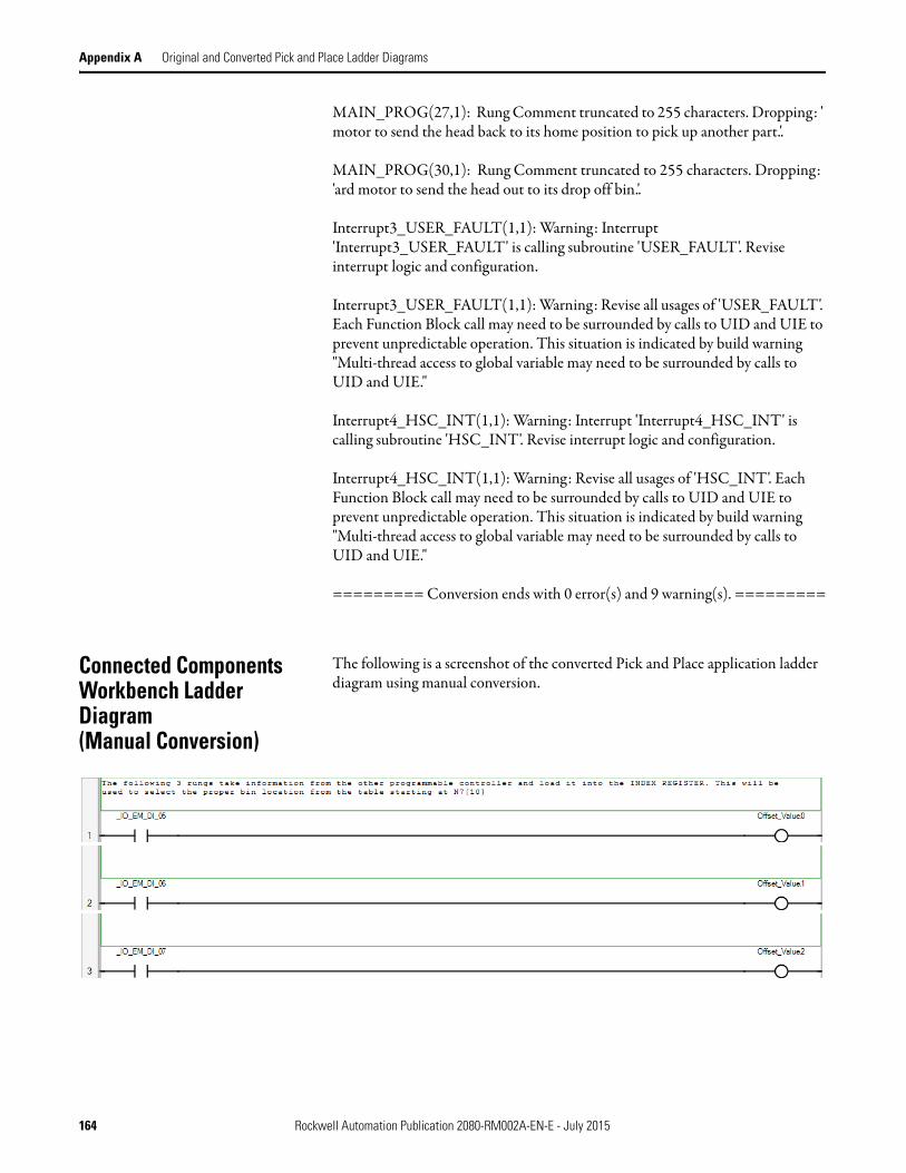
Appendix A Original and Converted Pick and Place Ladder Diagrams
MAIN_PROG(27,1): Rung Comment truncated to 255 characters. Dropping: ' motor to send the head back to its home position to pick up another part.'.
MAIN_PROG(30,1): Rung Comment truncated to 255 characters. Dropping: 'ard motor to send the head out to its drop off bin.'.
Interrupt3_USER_FAULT(1,1): Warning: Interrupt 'Interrupt3_USER_FAULT' is calling subroutine 'USER_FAULT'. Revise interrupt logic and configuration.
Interrupt3_USER_FAULT(1,1): Warning: Revise all usages of 'USER_FAULT'. Each Function Block call may need to be surrounded by calls to UID and UIE to prevent unpredictable operation. This situation is indicated by build warning "Multi-thread access to global variable may need to be surrounded by calls to UID and UIE."
Interrupt4_HSC_INT(1,1): Warning: Interrupt 'Interrupt4_HSC_INT' is calling subroutine 'HSC_INT'. Revise interrupt logic and configuration.
Interrupt4_HSC_INT(1,1): Warning: Revise all usages of 'HSC_INT'. Each Function Block call may need to be surrounded by calls to UID and UIE to prevent unpredictable operation. This situation is indicated by build warning "Multi-thread access to global variable may need to be surrounded by calls to UID and UIE."
========= Conversion ends with 0 error(s) and 9 warning(s). =========
Connected Components Workbench Ladder Diagram (Manual Conversion)
The following is a screenshot of the converted Pick and Place application ladder diagram using manual conversion.
164 Rockwell Automation Publication 2080-RM002A-EN-E - July 2015
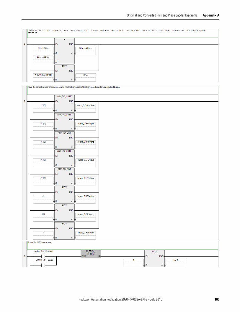
Original and Converted Pick and Place Ladder Diagrams Appendix A
Rockwell Automation Publication 2080-RM002A-EN-E - July 2015 165
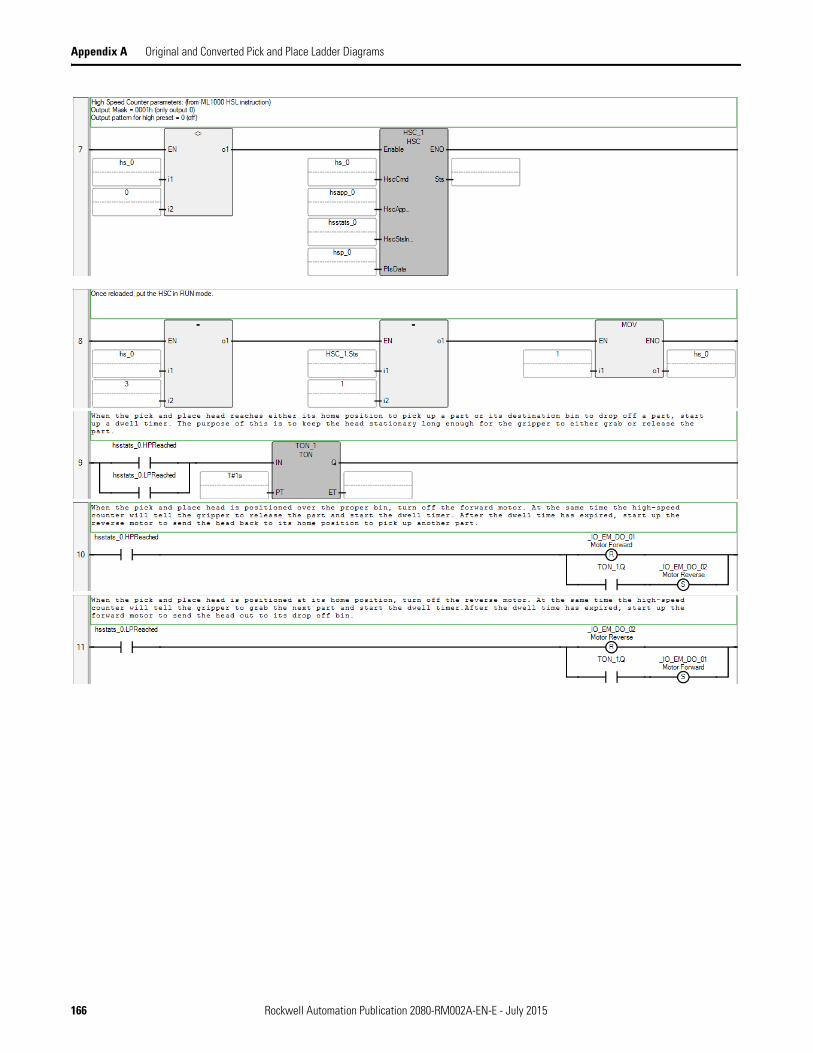
Appendix A Original and Converted Pick and Place Ladder Diagrams
166 Rockwell Automation Publication 2080-RM002A-EN-E - July 2015

Rockwell Automation Publication 2080-RM002A-EN-E - July 2015 167

Rockwell Otomasyon Ticaret A.Ş., Kar Plaza İş Merkezi E Blok Kat:6 34752 İçerenköy, İstanbul, Tel: +90 (216) 5698400
Publication 2080-RM002A-EN-E - July 2015 168Copyright © 2015 Rockwell Automation, Inc. All rights reserved.
Rockwell Automation Support
Rockwell Automation provides technical information on the Web to assist you in using its products. At http://www.rockwellautomation.com/support/, you can find technical manuals, a knowledge base of FAQs, technical and application notes, sample code and links to software service packs, and a MySupport feature that you can customize to make thebest use of these tools.
For an additional level of technical phone support for installation, configuration, and troubleshooting, we offer TechConnect support programs. For more information, contact your local distributor or Rockwell Automation representative, or visit http://www.rockwellautomation.com/support/.
Installation Assistance
If you experience a problem within the first 24 hours of installation, review the information that is contained in this manual.You can contact Customer Support for initial help in getting your product up and running.
New Product Satisfaction Return
Rockwell Automation tests all of its products to ensure that they are fully operational when shipped from the manufacturing facility. However, if your product is not functioning and needs to be returned, follow these procedures.
Documentation Feedback
Your comments will help us serve your documentation needs better. If you have any suggestions on how to improve this document, complete this form, publication RA-DU002, available at http://www.rockwellautomation.com/literature/.
United States or Canada 1.440.646.3434
Outside United States or Canada
Use the Worldwide Locator at http://www.rockwellautomation.com/support/americas/phone_en.html, or contact your local Rockwell Automation representative.
United States Contact your distributor. You must provide a Customer Support case number (call the phone number above to obtain one) to your distributor to complete the return process.
Outside United States Please contact your local Rockwell Automation representative for the return procedure.