2019 nepp etw: bga underfill for cots ruggedization · current status of nasa • underfill enables...
TRANSCRIPT

BGA Underfill for COTS Ruggedization
Gustavo Maldonado
Joseph Riendeau
Eric Suh
Jet Propulsion Laboratory, California Institute of Technology
NASA Electronic Parts and Packaging Program (NEPP)
2019 Annual NEPP Electronic Technology Workshop (ETW)
June 18th, 2019
1

Underfill History
• Early ceramic flip chip did not have underfill.
– Si : CTE ~3ppm/°C Ceramic substrate ~8ppm/°C
– Had hermetic seal
– Had die size limit
• 1987 : Hitachi used underfill and demonstrated
improvement of temperature cycling life of flip chip. IBM
also saw the same effect.
• 1991 : IBM introduced organic flip chip (17ppm/°C).
– Underfill was implemented in this product.
• ‘2000s : Widespread of handheld device
– CSP/BGA were underfilled for drop reliability.
• Temperature cycling life of BGA and CSP can be also
enhanced by underfill, when done right.
2

Current Status of NASA
• Underfill enables flip chip solder bump to survive temp
cycling. ex) Class-Y parts.
• Plastic BGA parts are becoming reality for flight
missions.
– Organic class-Y parts 38535 spec development activity
– COTS parts and assemblies for small missions
– Custom SiP for flagship missions
• Underfill can be used for enhancing BGA reliability:
– shock, vibe, and thermal cycling reliability.
• Underfill can be also used for ruggedizing parts other
than BGAs.
– Ex) TSOP, CSP, etc3
PCB
PBGA
Flip chip Underfill
BGA underfill

• How underfill works:
– Redistribute stress on the solder joints to underfill.
4
Package Ruggedization Using Underfill
• Requirement for flip chip due to large CTE mismatch and
small standoff height.
• Package size and standoff height dependent for BGA.
CTE 3ppm/⁰C
CTE 17 ppm/⁰C

Data from Literature
• Conventional BGA and CSP have good temp cycle
performance which can be improved by underfill –
Application Specific
• uBGA and TSOP temp cycle life can be significantly
improved by underfill – Technology Enabler
5
Temp cycle
condition
Without underfill With underfill Data source
TSOP 0 to 100ºC 1st failure at 150 cyc No failure until 3000 cyc Alan Emerick et al,
1993
CSP -40 to 125ºC N63 ~ 3300 1 or no failure up to 5200
cyc, out of 180 samples.
Jing Liu et al, 2003
uBGA -65 to 125ºC 4 of 10 failed by 800 cyc No failure up to 4500 cyc Jong-Min Kim et al,
2003
BGA -40 to 125ºC N63~4690 N63~5780 Haiyu Qi et al, 2009

COTS Part Challenges
• Commercial BGAs use lead-free solder
– Require higher temperature to assemble, spheres may not melt
during reflow when assembled onto a flight board.
– Several factors may affect final solder joint composition.
• Paste volume, peak reflow temperature, time above liquidus, etc.
– Mixed SnPb-PbFree solder joint reliability is not fully understood.
– Cracking from mechanical shock.
6
SnPb Sphere
w/SnPb Paste
Pb-free Sphere
w/ SnPb Paste
No Melting
Pb-free Sphere
w/ SnPb Paste
Partial Mixing

COTS Assembly Challenges
• COTS assemblies are becoming increasingly common in flight missions.
– Some of current class-D missions are using COTS assemblies.
• COTS assemblies are not built or inspected to NASA requirements. Insufficient and inconsistent workmanship.
– Ex)
• Developing an adequate ruggedization methodology can bring up the reliability of COTS assemblies.
7
* This assembly
passed initial
electrical test (with
no solder wetting).

Underfill Properties
• Key BGA underfill material properties
• Desired properties
– Low outgassing
– Reworkability
– Ease of dispense
8
Underfill Tg (°C) CTE (ppm/K) ModulusCure time
(min)Reworkability Outgassing
SUF1589-1 120 23/80 Bending / 13 GPa 80 No Pass
UF3811 124 61/190 Storage / 2.45 GPa @25C 60 Yes Pass
Loctite 3549 38 55/177 Storage / 2 GPa @22C 5 Yes Fail
SMC-386GM 75 60 Flexural / 2.5 GPa 30 Yes TBD
Loctite 3563 130 35/110 Tensile / 2.8 GPa 7 No TBD
UF3800 69 52/188 Storage / 3.08 GPa @25C 8 Yes TBD
UF3810 102 55/171 Storage / 2.99 GPa @25C 8 Yes TBD
Loctite 3128 45 40/130 Tensile / 3.9 GPa 20 No TBD
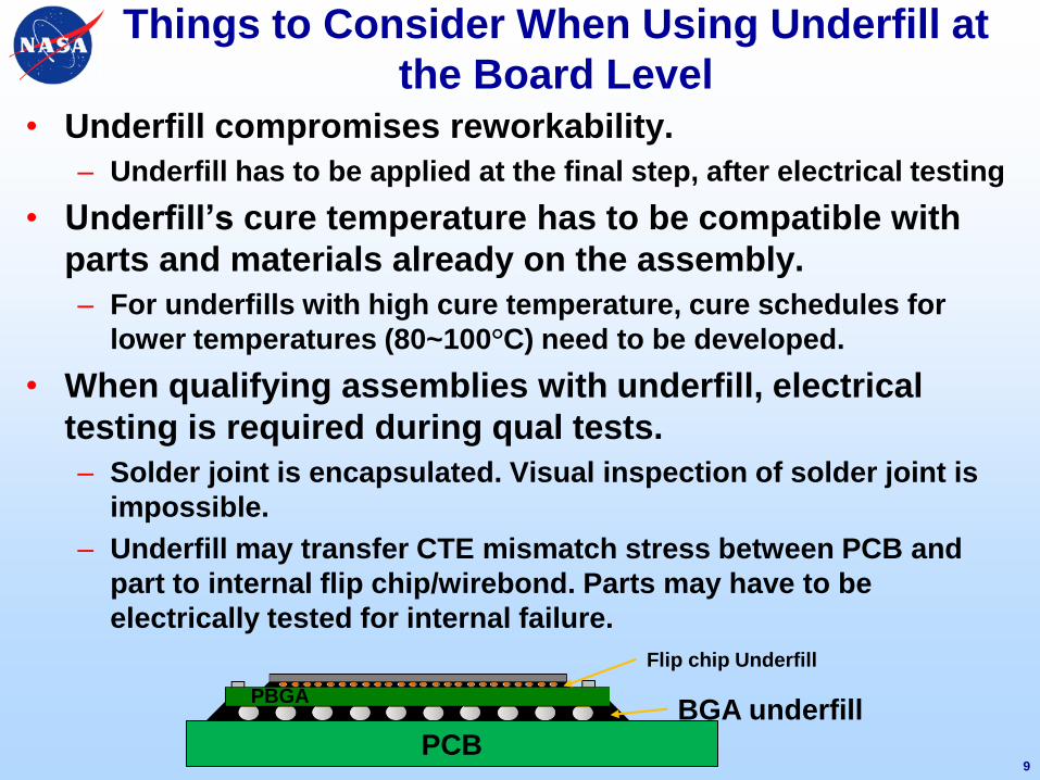
Things to Consider When Using Underfill at
the Board Level
• Underfill compromises reworkability.
– Underfill has to be applied at the final step, after electrical testing
• Underfill’s cure temperature has to be compatible with
parts and materials already on the assembly.
– For underfills with high cure temperature, cure schedules for
lower temperatures (80~100°C) need to be developed.
• When qualifying assemblies with underfill, electrical
testing is required during qual tests.
– Solder joint is encapsulated. Visual inspection of solder joint is
impossible.
– Underfill may transfer CTE mismatch stress between PCB and
part to internal flip chip/wirebond. Parts may have to be
electrically tested for internal failure.
9
PCB
PBGA
Flip chip Underfill
BGA underfill

Underfill material down selection plan
• Outgassing
• Cure temperature compatibility with other parts and
polymers in assembly.
• Check for lower temperature cure viability.
– Ex ) 150C/7min to 100C/2hours
• Check for flexibility in application requirements.
– Required equipment
– Dispense temperature
– Ventilation requirements
10
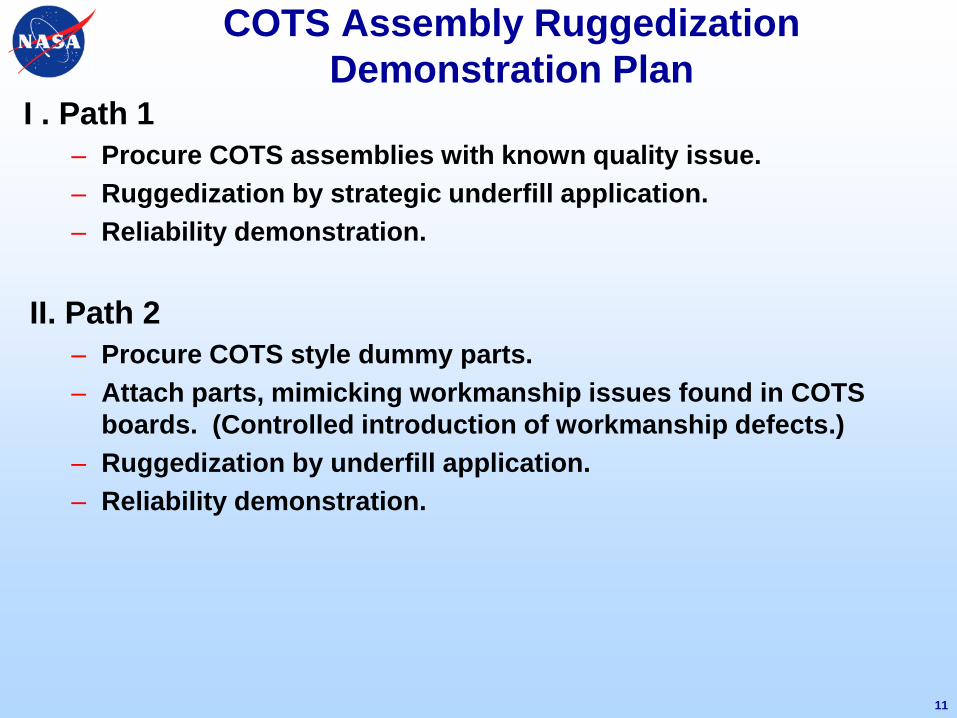
COTS Assembly Ruggedization
Demonstration PlanI . Path 1
– Procure COTS assemblies with known quality issue.
– Ruggedization by strategic underfill application.
– Reliability demonstration.
II. Path 2
– Procure COTS style dummy parts.
– Attach parts, mimicking workmanship issues found in COTS
boards. (Controlled introduction of workmanship defects.)
– Ruggedization by underfill application.
– Reliability demonstration.
11

Summary
• Underfill can enhance reliability.
• COTS BGA parts & assemblies present new reliability
challenges.
• Ruggedization of COTS assemblies will be demonstrated.
12