warning · 2019. 10. 23. · -*-*-*-*- warning -*-*-*-*-this equipment generates and uses radio...
TRANSCRIPT


-*-*-*-*- WARNING -*-*-*-*-
THIS EQUIPMENT GENERATES AND USES RADIO FREQUENCY ENERGY AND IF NOT INSTALLED AND USED PROPERLY, THAT IS, IN STRICT ACCORDANCE WITH THE MANUFACTURER’S INSTRUCTIONS, MAY CAUSE INTERFERENCE TO RADIO AND TELEVISION RECEPTION. IT HAS BEEN TYPE TESTED AND FOUND TO COMPLY WITH THE LIMITS FOR A CLASS B COMPUTING DEVICE IN ACCORDANCE WITH THE SPECIFICATIONS IN SUBPART J OF PART 15 OF THE FCC RULES, WHICH ARE DESIGNED TO PROVIDE REASONABLE PROTECTION AGAINST SUCH INTERFERENCE IN A RESIDENTIAL INSTALLATION. HOWEVER, THERE IS NO GUARANTEE THAT INTERFERENCE WILL NOT OCCUR IN A PARTICULAR INSTALLATION. IF THIS EQUIPMENT DOES CAUSE INTERFERENCE TO RADIO OR TELEVISION RECEPTION, WHICH CAN BE DETERMINED BY TURNING EQUIPMENT OFF AND ON, THE USER IS ENCOURAGED TO TRY TO CORRECT THE INTERFERENCE BY ONE OR MORE OF THE FOLLOWING MEASURES:
* REORIENT THE RECEIVING ANTENNA.* RELOCATE THE COMPUTER WITH RESPECT TO THE
RECEIVER.* MOVE THE COMPUTER AWAY FROM THE RECEIVER.* PLUG THE COMPUTER INTO A DIFFERENT OUTLET SO
THAT THE COMPUTER AND RECEIVER ARE ON DIFFERENT BRANCH CIRCUITS.
* IF NECESSARY, THE USER SHOULD CONSULT THE DEALER OR AN EXPERIENCED RADIO/TELEVISION TECHNICIAN FOR ADDITIONAL SUGGESTIONS.
THE USER MAY FIND THE FOLLOWING BOOKLET PREPARED BY THE FEDERAL COMMUNICATIONS COMMISSION: “HOW TO IDENTIFY AND RESOLVE RADIO—TV INTERFERENCE PROBLEMS”. THIS BOOKLET IS AVAILABLE FROM THE U.S. GOVERNMENT PRINTING OFFICE, WASHINGTON, DC 20402, STOCK No. 004—000—00345—4.
CAUTION ~
THIS EQUIPMENT MUST ONLY USE SHIELDED CABLES THAT ARE SUPPLIED BY PASSPORT DESIGNS, INC. THESE CABLES, AS SUPPLIED WITH THE UNIT, ARE DESIGNED TO REDUCE INTERFERENCE AS REQUIRED BY PROPER ENGINEERING AND MANUFACTURING METHODS AND BY REGULATIONS ENFORCED BY THE FEDERAL COMMUNICATIONS COMMISSION. PRIOR TO USING ANY INTER-CONNECTING CABLES WHICH WERE NOT SPECIFICALLY SUPPLIED WITH THE UNIT, CONTACT PASSPORT DESIGNS, INC. FOR INSTRUCTIONS.

NOTICESPassport Designs, Inc. reserves the right to make improvements in the
product described in this manual at any time and without notice.This manual is copyrighted. All rights are reserved. No part of this
manual may be copied, reproduced, translated, or reduced to any electronic medium or machine readable form without the written consent of Passport Designs, Incorporated, 625 Miramontes Suite 103, Naif Moon Bay, CA 94019.
Passport Designs, Inc. makes no warranties either express or implied with respect to this manual or with respect to the product described in this manual, its merchantability, or fitness for any particular purpose.
Passport Designs make certain limited warranties with regard to defective products.
WARRANTYPassport Designs, Inc. warrants to the original purchaser of this computer
hardware product that the product will be free from defects in materials or workmanship for a period of 90 days from the date of purchase. This warranty will be null and void if any component appears to have been damaged due to unauthorized service or misuse. Passport Designs reserves the right to repair or replace defective hardware at its discretion.
This warranty is in lieu of all other warranties, whether oral or written, expressed or implied. Any implied warranties, including implied warranties of merchantability and fitness for a particular purpose, are expressly limited in duration to ninety days from the date of purchase. Passport Designs shall not be liable for any incidental, consequential, or collateral damages resulting from use and/or operation of its products, or for breach of any expressed or implied warranty.
Some states do not allow the exclusion of incidental or consequential damages or limitations on how long an implied warranty lasts, so the above limitation or exclusion may not apply to you. This warranty gives you specific legal rights; you may also have other rights which vary from state to state.
* Apple II+, Apple //e, and Applesoft BASIC are trademarks ofApple Computer, Inc.
* Commodore 64 is a trademark of Commodore Business Machines, Inc.* Korg is a trademark of Unicord.* Roland is a trademark of Roland Corp, U.S.* Linn is a trademark of Linn Electronics, Inc.* Oberheim is a trademark of Oberheim Electronics, Inc.* E-mu end Drumulator are trademarks of E-mu Systems, Inc.
Manual written by Bruce Bethke & John Borowicz1st Edition, March 1985
Published by Passport Designs, Inc.625 Miramontes St.
Half Moon Bay, CA 94019(415) 726—0280
All manual contents:(c) 1985 Passport Designs, Incorporated
ALL RIGHTS RESERVED2

MIDI INTERFACE CARDUSER MANUAL & TECHNICAL NOTES
FOR MODELS MH-01A & MH-02A WITH TAPE SYNCFOR APPLE //, //e
&MODEL MH-01C FOR COMMODORE 64
CONTENTS
page
1.0 Introduction 4
2.0 System Requirements & Setup 5
2.1 Installation: APPLE // Version 62.2 Installation: COMMODORE 64 Version 72.3 System Diagram 82.4 connecting Drum Machines 92.5 Connecting & Using Tape Sync 11
3.0 Introductory Programming 13
3.1 MIDI Codes 17
4.0 Technical Notes 19
4.1 Apple // Hardware Addresses 204.2 Commodore 64 Hardware Addresses 214.3 Initialization & Operation Codes 224.4 6840 PTM Description 234.5 6850 ACIA Description 294.6 Additional Sources of Information 36
3

1.0 INTRODUCTION
Passport's Musical Instrument Digital Interface (MIDI)
card is a simple, reliable, linking device allowing data communi-
cation between MIDI-equipped musical instruments and Apple II,
II+, //e, or Commodore 64 microcomputers.
This document is divided into four sections:
1.0 is introductory material;
2.0 covers installation and system configuration, and is "must” reading for all users;
3.0 covers common MIDI codes and beginning—level sample applications;
4.0 covers hardware control and addressing. It is intended primarily as a resource for experienced programmers.
Please note that the sections on MIDI codes and applications
in this document are intended as introductory material only. For
a thorough study of MIDI command codes and data types, we advise
obtaining a copy of the MIDI SPECIFICATION from the International
MIDI Association (see pg.36).
4

2.0 SYSTEM REQUIREMENTS & SETUP
The following hardware is required in order to use the MIDI interface:
• One Apple II-type computer with at least 48K RAM, video monitor, and one disk drive with disk controller card.
- OR -
• One Commodore 64 computer with monitor or television, and one disk drive.
• One MIDI—equipped synthesizer.
• At least two MIDI 5—pin DIN cables (supplied with unit).
• Amplifier, headphones, or other audio monitoring system.
• OPTIONAL — Programmable drum machine.
• OPTIONAL - MIDI Drum Sync Cable Kit. (DCK-l) Available from your local dealer, or directly from Passport Designs.
• OPTIONAL - Two cables with male RCA-type plugs, for use with TAPE SYNC. (FOR APPLE MODEL MH-02A ONLY)
In the Passport system, all instruments are connected in daisy—chain format. That is, the "first” instrument connects directly to the computer via MIDI IN and MIDI OUT. (Position in the chain has no relationship to CHANNEL NUMBERS of the receiving instruments.)
MIDI THRU on the “first” instrument connects to MIDI IN on the “second” instrument; MIDI THRU on the “second” instrument to MIDI IN on the “third” instrument; and so on down the chain.
Note that in this system, only the “first” instrument transmits to the computer. NO instruments transmit directly to each other. However, ALL instruments in the system receive from the computer, and thereby from the “first” instrument.
5

2.1 INSTALLATION: APPLE // VERSION
With the power off (pulling the plug is even better), open the top of your computer and locate slot #2. When facing the key- board end of your computer, this is the second slot from the left side in Apple //es, or the third slot from the left side in Apple II’s and II+’s. Insert the MIDI interface card into slot #2; it can only fit one way. After the card is in the slot:
1.) Feed your MIDI 5-pin DIN cables through the back of your computer. (Apple //e owners: The cables will fit through hole #12 in the backplate of the computer.)
2.) Connect the Computer MIDI OUT to Synthesizer MIDI IN.
3.) Connect the Synthesizer MIDI OUT to Computer MIDI IN.
4.) OPTIONAL - If you have a non—MIDI drum machine, connect one end of the DCE-l Drum Cable Kit to DRUM on the interface card, and turn to Section 2.4. IF YOU HAVE A MIDI DRUM MACHINE, DO NOT USE THIS CONNECTION~
5.) OPTIOINAL (FOL MODLL MH—02A ONLY) — If you have a multi—track tare recorder and wish to use TAPE SYNC, connect RCA—type cables to the PCA IN and OUT jacks on the interface, and turn to Sec. 2.5.
6.) Close the top of your computor and reconnect power.
If you have multiple instruments in your system, only one synthesizer is connected directly to the computer. Additional instruments tie into the system via cables from MIDI THRU on one instrument to MIDI IN on the next.
6

2.2 INSTALLATION: COMMODORE 64 VERSION
Installing your MIDI interface is simple: With the power off, plug the MIDI interface label side up into the expansion slot on the right rear corner of your Commodore 64. Then:
1.) Connect the Computer MIDI OUT to Synthesizer MIDI IN.
2.) Connect the Synthesizer MIDI OUT to Computer MIDI IN.
3.) OPTIONAL - If you have a non—MIDI drum machine, connect one end of the DCK—l Drum Cable Kit to DRUM on the inter- face card, and turn to Section 2.4. IF YOU HAVE A MIDI DRUM MACHINE, DO NOT USE THIS CONNECTION!
If you have multiple keyboards in your MIDI system, only one synthesizer is connected directly to the computer. Additional instruments tie into the system via cables from MIDI THRU on one instrument to MIDI IN on the next.
7

2.3 SYSTEM DIAGRAM
Remember, this is just the physical wiring of the system. The actual destination of transmitted data is determined by the MIDI CHANNEL assignment of the transmitting software, and the CHANNEL and MODE controls of the receiving instruments in the system; not by the interface.
Also remember, in multiple—instrument systems the instrument connected directly to the computer is the recording keyboard. All other instruments are play-only
8

2.4 CONNECTING DRUM MACHINES (OPTIONAL)
Using the Passport DCK-l Drum Sync Cable Kit, moat brands of drum machine can be integrated into your MIDI system. With Drum Sync, your MIDI system generates the CLOCK and START/STOP signals for the drum machine. Your drum machine must be capable of accep-ting external CLOCK signals for this to work.
The Drum Sync Cable Kit consists of two parts: 1) a male—to— male DIN 5-pin cable, and. 2) a female DIN “Y” cable terminating with 2 quarter—inch phone plugs.
MIDI-eguipped Drum MachinesThe signals available through the Drum Sync jack are analog, not MIDI information. DO NOT CONNECT DRUM SYNC DIRECTLY TO MIDI IN of MIDI-equipped drum machines.
Drum machines equipped with MIDI are connected via MIDI OUT, IN, and THRU jacks, just like any other synthesizer.
Roland or Korg Drum MachinesIf you use a Roland, Korg, or other non—MIDI drum machine equipped with a 5-pin DIN socket for external sync:
1) Connect the male-to—male DIN cable from the DRUM output of the MIDI interface to the external sync input on the drum machine;
2) Set the SYNC INPUT/OUTPUT switch to INPUT.
Linn, Oberheim, Drumulator, and othersIf you're using a drum machine without a DIN sync connector, you must use both cables in the Drum Sync Cable set.
1) Connect the male—to—male DIN cable to the DRUM output of the MIDI interface;
2) Attach the female DIN “Y cord to the male DIN cable;
3) Insert the straight phone plug into the CLOCK input of the drum machines, and the right angle plug into the START/STOP (or footswitch) input of the drum machine.
9

Drum Sync Clock RateThe MIDI standard for timinq pulses is 24 CLOCK pulses per quarter note beat. Different non—MIDI drum machines use different clock rates. Older E—mu Drumulators use 12 clocks/ quarter note; new Drumulators and Rolands use 24 clocks per quarter note. Korg uses 48 clocks per quarter note; Oberheim uses 96 clocks/quarter note.
When running commercial software, you will need to allow for these differences in programming the drum machine for syn-chronization with the MIDI system.
Drum synchronization is not automatic. If you are writing your own software for this interface, you will need to make provision for generating drum sync signals.
Drum Sync PinoutWhen operating under software control the Drum Sync connector outputs two signals:
START/STOP - Normally high, pulses low (& returns high) to toggle running state of drum machine;
CLOCK - - - +5V at a rate of 24 clocks/qtr. note. Nor-mally off, turns on when START is sent.
GND
START/STOP CLOCK
10

2.5 CONNECTING & USING TAPE SYNC (OPTIONAL)
(FOR APPLE MODEL MH—02A ONLY)
One of the most significant features of the MH—02 Interface is TAPE SYNC. When used with the appropriate software, this inter- face will WRITE sync information onto one track of a multi—track tape deck. The tape can then be played back and the sync track READ by the interface, producing perfect synchronization of multiple sequencer and/or drum machine tracks, regardless of when they're recorded.
The first crucial part of the process is appropriate software. TAPE SYNC is not automatic; you must have a sequencer program which supports it, At this time, MIDI/4 PLUS and MIDI/8 PLUS will make use of the TAPE SYNC features of the MH—02 Interface; owners of older versions-of MIDI/4 are advised to contact Passport Customer Service and ask about the Software Update Program.
While the operation of TAPE SYNC is described in detail in our software manuals, wed like to offer a few pointers here:
CONNECTIONS: The TAPE SYNC jacks are 2 RCA—type female jacks on the MH—02 Interface. For best results, bypass your mixer and connect TAPE SYNC OUT directly to LINE IN of the tape deck channel you'll be using for the sync track. Connect LINE OUT of the tape deck to TAPE SYNC IN on the interface. This will provide a cleaner signal. ABOVE ALL, NEVER USE DOLBY OR DBX NOISE REDUCTION ON THE SYNC TRACE! -
THE TAPE: The integrity of your tape is crucial. Splices, drop- outs, or wrinkles in the tape can render the recorded sync track worthless.
BEST PROCEDURE: Make sure all tracks are recorded in the sequencer before going to tape. No sequencer track can be longer than the SYNC TRACE on the tape, and the sync code is only written onto the tape while the sequencer is running. Therefore, the
11

sync track is Only as long as longest track in the sequencer at the time the sync track is recorded.
a.) Don’t turn on the TAPE SYNC WRITE in the software until you’re ready to record the SYNC TRACK.
b.) Watch your VU meters. TAPE SYNC works beat when the sync track is recorded and played back at —3 dB.
c.) TAPE SYNC works best if you record the SYNC TRACK first, with the sequencer running, but not recording the music tracks. Record just the WRITE TAPE SYNC output. Then set the sync track to normal playback mode and begin laying down the sequencer and drum machine tracks while READING the sync track off the tape.
We recommend this procedure because we’ve found that many low—priced multi—track tape decks —— particularly integrated mixer/cassette units —— have relatively poor audio quality in “simul-sync” playback mode and the sync track data can get lost in the noise.
d.) Sync track data consists of a "ready" code, followed by a running’ code. Both codes must be present for tape sync to work correctly. This means, when recording the sync track, start the tape rolling before you start seq-uencer playback. When overdubbing later tracks, never “cue up” the tape to the first beat of the song; always start at least 1 beat before the beginning of the song in order to catch the “ready” code on the sync track.
e.) There is no TEMPO information in the sync track. It’s up to you to set the TEMPO of your sequencer correctly.
f.) Provided they are connected to your MN-02 Interface and the “utilities" in your MIDI/4 PLUS or MIDI/8 PLUS pro-gram are set correctly, external MIDI sequencers and both MIDI and non—MIDI drum machines will start and run in sync with the tape track.
12

3.0 INTRODUCTION TO PROGRAMMING THE MIDI INTERFACE
While we haven’t the space to thoroughly cover MIDI program-ming in this manual, we will touch briefly on the subject for those users who decide to write their own programs.
Why? Passport is a software publisher, and like most publi-shers we are interested in good independently written programs to publish. That’s our business. If you’d like to know more, write us and request our submissions guidelines.
The MIDI interface is easily accessed from assembly language, BASIC, and other programming languages that allow direct manipula-tion of Input/Output (I/O) addresses. As music is an extremely time—sensitive application, most professional programming is done in assembly language. However, even beginning BASIC programmers can write entertaining and enjoyable MIDI music programs. (Please note: While Applesoft or Commodore BASIC programs can play MIDI musical instruments, they are not able to record.)
The program that follows is a simple demonstration of MIDI playback under Applesoft BASIC control. When typed into your Apple and RUN it “plays’ a two octave note sequence at a steady tempo, pauses to allow entry of a transposition value, then replays the sequence in transposition.
This program, with slight modification, can also be typed in and RUN on a Commodore 64. Host importantly, you must change the definitions of ACIA CONTROL and DATA register addresses in lines 3060 and 3070 to read:
3060 AC = 568403070 AD = 56841
It is also necessary to omit lines 1240, 1310, 2050, 2080, and 2110, as Commodore BASIC doesn’t accept HTAB and VTAB commands.
13

100 REM ------------------------------110 REM - MIDI DATA PLAYBACK DEMO -120 REM - APPLESOFT BASIC -130 REM -(C)1984 PASSPORT DESIGNS INC-140 REM - ALL RIGHTS RESERVED -150 REM - -160 REM - VERSIOM 1.1 9/6/84 -170 REM - PROGRAMMER: BRUCE BETHKE -200 REM -----------------------------210 REM220 GOSUB 2000: REM DRAW SCREEN230 GOSUB 3000: REM DEFINE VARIABLES235 GOTO 1000: REM BEGIN PLAYBACK240 REM250 REM260 REM -----------------------------270 REM - SUBROUTINES -280 REM -----------------------------290 REM300 REM -- WAIT FOR ACIA TO CLEAR ---310 FOR TIM = 1 TO 4: NEXT RETURN320 REM330 REM400 REM —- WAIT FOR NOTES DURATION -—410 FOR TIM = 1 TO OUR: NEXT : RETURN420 REM430 REM500 REM ------TURN OFF OLD NOTE ------ 510 POKE AD,OFFKY: GOSUB 310520 POKE AD,OLDEY: GOSUB 310530 POKE AD,VOFF: GOSUB 310540 RETURN550 REM560 REM600 REM ----- TURN ON NEW NOTE -----610 POKE AD,KEYDN: GOSUB 310620 POKE AD,NEXKY: GOSUB 310630 POKE AD,VMAX: GOSUB 310640 RETURN650 REM660 REM1000 REM --------------------------1010 REM - BEGIN PLAYBACK —1020 REM --------------------------1030 REM1040 FOR N = 1 TO 241050 READ NEXEY1060 NEXKY = NEXKY + T: REM TRANSPOSE1070 GOSUB 510: REM TURN OFF PREVIOUS NOTE1080 GOSUB 610: REM PLAY CURRENT NOTE1090 GOSUB 410: REM WAIT ONE NOTE’S DURATION1100 OLDEY = NEXEY: REM CURRENT NOTE BECOMES PREVIOUS NOTE1110 NEXT N: REM GET NEXT NOTE1120 REM
14

1130 REM ----------------------------1140 REM - AT END OF DATA, TURN OFF -1150 REM - LAST NOTE PLAYED -1160 REM ----------------------------1175 GOSUB 4101180 POKE AD,OFFKY: GOSUB 3101190 POKE AD,OLDKY: GOSUB 3101195 POKE AD,VOFF: GOSUB 3101197 REM1200 REM ----------------------------1210 REM - EXIT / TRANSPOSE PROMPT -1220 REM ----------------------------1240 VTAB 12: HTAB 101250 PRINT “CONTINUE (Y/N)";: INPUT A$1260 IF (AS = “Y” OR A$ = y) THEN 13001270 HOME : END1290 REM1300 REM ---- CONTINUE PLAYBACK ---1310 VTAB 14: HTAB 31320 PRINT “TRANSPOSE VALUE (+/- 0...36)”;: INPUT A$1330 T = VAL (A$)1340 IF (T > = — 36) AND (T < = 36) THEN 14001350 HOME : GOSUB 2000: GOTO 13101360 REM1400 RESTORE : GOTO 10401410 REM =======================1500 REM1900 REM2000 REM -------------------------2010 REM - DRAW SCREEN -2020 REM -------------------------2040 HOME : PRINT CHR$ (7): REM BEEP!2050 VTAB 1: HTAB 7: INVERSE2060 PRINT “MIDI PLAYBACK DEMONSTRATION”2070 NORMAL2080 VTAB 3: HTAB 5: INVERSE2090 PRINT “(C) 1984 PASSPORT DESIGNS, INC.”21q0 NORMAL2110 VTAB 5: HTAB 5: PRINT”**********************************" 2120 RETURN2130 REM2140 REM3000 REM --------------------------3010 REM - DEFINE VARIABLES —3020 REM --------------------------3030 REM3040 REM ACIA CONTROL AND DATA REGISTERS3050 REM WITH MIDI CARD IN SLOT#23060 AC = 49320: REM ACIA CONTROL3070 AD 49321: REM ACIA DATA3080 OFFKY = 128: REM KEY OFF STATUS BYTE3090 KEYDN = 144: REM KEY ON STATUS BYTE3100 VOFF = 0: REM KEY VELOCITY 03110 VMAX = 127: REM KEY VELOCITY = 1273120 OLDKY = 0: REM “OLD” KEY ID NUMBER3130 NEXEY 0: REM “NEW” KEY ID NUMBER3140 DUR = 50: REM NOTE DURATION3150 T = 0: REM TRANSPOSITION VALUE 153160 A$ = ““: REM INPUT STRING VARIABLE

3180 REM3200 REM ----------------------------3210 REM - RESET & CONFIGURE ACIA -3220 REM ----------------------------3230 REM3240 POKEAC,19: POKE AC,173250 RETURN3300 REM3400 REM4000 REM ----------------------------4010 REM - KEY ID (NOTE) DATA TABLE -4020 REM ----------------------------4030 REM4040 DATA 60,61,62,63,64,654050 DATA 66,67,68,69,70,714060 DATA 72,71,69,68,67,664070 DATA 65,64,63,62,61,604080 REM4090 REM
16

3.1 MIDI CODES
The following 6850 AdA and MIDI codes are used in the example program (the example program does not use the 6840 Timer). MIDI codes shown are valid only if the synthesizer is set to receive on MIDI CHANNEL 01.
For a complete listing of MIDI codes, see the IRA MIDI Specification.
ACIA CODE 19 —- RESET (line 3240)This value poked into the ACIA control register resets the ACIA. This must be done before any other configuration code can be sent to the ACIA.
ACIA CODE 17 -- MASK INTERRUPTS (line 3240)Poking this value into the ACIA control register sets the ACIA to generate no interrupts to the Apple.
MIDI CODE 128 -- KEY OFF (line 3080, 510)MIDI messages consist of a status byte followed by one or two data bytes (depending on the type of message). Status bytes are always greater than 127; data bytes are always less than 128.
Both status bytes and data bytes are poked into the ACIA data register.
Code 128 (KEY OFF) must be followed by 2 data bytes: a key i.d. number (line 520) indicating which note to turn off, and a key velocity (line 530).
17

4.0 TECHNICAL NOTES
Passport MH—02 Interfaces are "clean and elegant" devices consisting of a 6850 Asynchronous Communications Interface Adapter (ACIA), a 6840 Programmable Timer Module (PTM), and computer bus interface circuitry. The simple design of the interface imposes the fewest possible restrictions on application software. Given proper software, any MIDI—equipped device can be addressed and controlled with this interface.
This section covers specific I/O addressing of the Apple end Commodore versions of the MH—02 Interface, frequently used AdA and PTM codes, and an introduction to the specifics of the ACIA and PTM.
For a complete description of the operating characteristics of the MC6840 PTM and MC6850 ACIA, see the 6840 and 6850 data sheets (available directly from Motorola).
19

4.1 APPLE // HARDWARE ADDRESSES
All Input/Output hardware addresses in the Apple II are slot dependent. Memory locations $C000 through SCFFF are allocated for I/O addresses; exact slot addresses are computed as follows:
BASE ADDRESS = $C080 + $n0
Where n equals the slot number (1 thru 7). The addresses given here are based on the assumption that the interface is installed in Slot #2 (base address $C0A0), the "standard” slot used for serial communications devices in the Apple.
DECIMAL HEX DESCRIPTION-----------------------------------------------------------------
49312 C0A0 6840 Timer control register 149313 C0Al 6840 Timer control register 249314 C0A2 High Byte Timer 1 value49315 C0A3 Low Byte Timer 1 value49316 C0A4 High Byte Timer 2 value49317 C0A5 Low Byte Timer 2 value49318 C0A6 High Byte Timer 3 (RESERVED)49319 C0A7 Low Byte Timer 3 (RESERVED)49320 C0A8 6850 control register49321 C0A9 6850 data register49326 C0AE Drum sync SET49327 C0AF Drum sync CLEAR
20
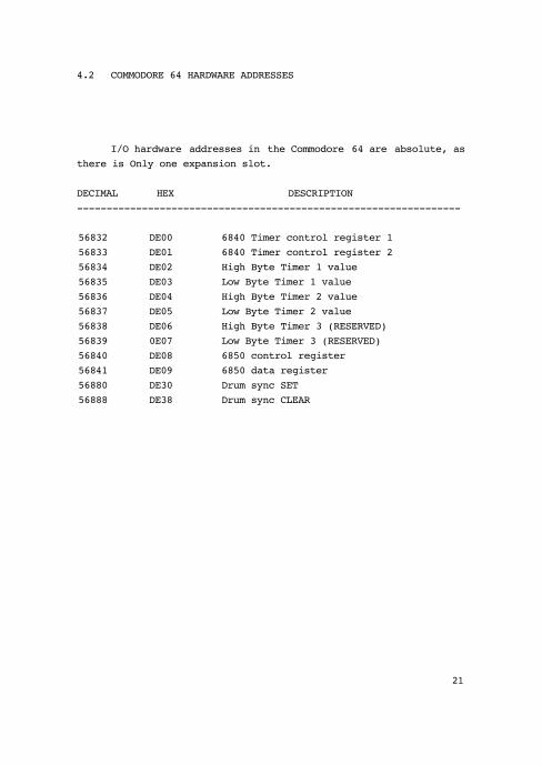
4.2 COMMODORE 64 HARDWARE ADDRESSES
I/O hardware addresses in the Commodore 64 are absolute, as there is Only one expansion slot.
DECIMAL HEX DESCRIPTION-----------------------------------------------------------------
56832 DE00 6840 Timer control register 156833 DE0l 6840 Timer control register 256834 DE02 High Byte Timer 1 value56835 DE03 Low Byte Timer 1 value56836 DE04 High Byte Timer 2 value56837 DE05 Low Byte Timer 2 value56838 DE06 High Byte Timer 3 (RESERVED)56839 0E07 Low Byte Timer 3 (RESERVED)56840 DE08 6850 control register56841 DE09 6850 data register56880 DE30 Drum sync SET56888 DE38 Drum sync CLEAR
21

4.3 INITIALIZATION & OPERATION CODES
The following values are used to set up the 6840 PTM and the 6850 ACIA to function in various capacities, and to control their operation.
Values relevant to the 6850 are poked into the 6850 Control and Transmit Data Registers. Values relevant to the 6840 are poked into the 6840 Timer Control Registers.
Timer& ACIA must be reset before configuration.
DECIMAL HEX BINARY DESCRIPTION-----------------------------------------------------------------
6 p 0 00 0000 0000 Let timers run8 T4 M 1 01 0000 0001 Turn off timers0
67 43 0100 0011 Reset the 6840 PTM6 A 17 11 0001 0001 No interrupts generated8 C5 I 19 13 0001 0011 Reset ACIA0 A
21 15 0001 0101 Turn off ACIA49 31 0011 0001 Generate interrupts during
Send only145 91 001 0001 Generate interrupts during
Receive Only177 Bl 1011 0001 Generate interrupts during
both Send & Receive
22

6840 PTM DESCRIPTION
4.4 MC6840 PROGRAMMABLE TIMER MODULE (PTM)
The Motorola MC6840 is a versatile timer module that is completely accessible to the programmer, appearing as memory locations in the I/O space. The module contains three timers which are independently programmable, cyclic in operation, contro- llable by external events or software, and are accessible by the microprocessor at any time.
Typically, a timer is loaded by storing two bytes of time data into its respective Counter Latch, which is subsequently trans-ferred into the Counter during the initialization phase. The counter is decremented every clock period until a predetermined condition causes it to halt or recycle.
SIMPLIFIED BLOCK DIAGRAM OF THE MC6840
23

6840 PTM DESCRIPTION
CONTROL REGISTERS
There are three Write-Only registers on the 6840 that are used to “control" the operation of the three onboard timers.
Control Register #2 is uniquely mapped in the I/O address space and may be addressed at any time.
The remaining two control registers (#1 & #3) share the same address. They are addressed by setting all of the Register Select inputs, the three least significant bits (lsb) of the address, to logic zero and using bit 0 of Control Register #2 as an additional addressing bit.
Given the Register Select lines are zero, if bit 0 of Control Register *2 is logic one, Control Register #1 is selected. If Control Register #2 bit 0 is logic zero, then Control Register #3 is selected (reserved).
TABLE #1
Register Select Operations Bits R/W=0 R/W=l2 1 00 0 0 CR2 bit 0=0, Write CR #3 No operation
CR2 bit 0=1, Write CR #10 0 1 Write Control Register#2 Read Status register0 1 0 Write MSB buffer register Read Timer #1 counter0 1 1 Write Timer #1 latches Read LSB buffer register1 0 0 Write NSB buffer register Read Timer #2 counter1 0 1 Write Timer #2 latches Read LSB buffer register1 1 0 Write MSB buffer register Read Timer #3 counter1 1 1 Write Timer #3 latches Read LSB buffer register
24

6840 PTM DESCRIPTION
The lsb of Control Register #1 is used as an Internal Reset bit. Setting this bit to logic one causes all counters to be set with the contents of their associated latches, all counter clocks to be disabled, and all timer outputs and interrupt flags to be reset. Conversely, when bit 0 of Control Register #1 is set to logic zero, all of the timers are allowed to operate in the modes specified by the remaining bits in the respective control registers.
The lsb of Control Register #3 is used as a selector for a divide—by—8 prescaler used with Timer #3 only.
TABLE #2
Control Register 1Bit 0 Function: Internal Reset bit 0 All timers allowed to operate1 Hold timers in present state
Control Register 2Bit 0 Function: Control Register Address bit
0 Control Register #3 may be written 1 Control Register #1 may be written
Control Register 3Bit 0 Function: Timer #3 Clock Control
0 Timer 3 clock is NOT prescaled 1 Timer 3 clock is prescaled (divide by 8)
The remaining bits (1—7) of each of the Control Registers select common functions with the effect restricted to the timer associated with the respective Control Register.
25

6840 PTM DESCRIPTION
Bit 1: Selects the clock source for the timer.
Bit 2: Determines whether the binsry dsts contained in the Counter Latches is treated asone single 16—bit word, or as two 8-bit Bytes.
Bits 3, 4, arid 5: Select the operating modes of the respective timers: Continuous, Single—shot, Freq-uency comparison, or Pulse Width Comparison. Conti-nuous (the most commonly used mode) is established by writing zeroes into bits 3 and 5 of the corres-ponding Control Register.
A Timer Reset (Internal Reset: Control Register #1, bit 0=1; or an External Reset=0) condition results in Counter initialization.
Bit 6: Is an Interrupt Mask and is used in conjunction with the interrupt flag bits of the Status Register It must be set (=1, logic One) if interrupts are to be recognized from the associated timer.
Bit 7: Enables the corresponding Timer Output, (This mode is not used).
TABLE #3
Control Registers 1 through 3Bit State Function1 0 Timer n* uses external clock source
Timer n uses (Enables) internal clock src2 0 Timer n 16-bit mode
Timer n dual 8-bit mode3 - Timer n Counter Mode & Interrupt Control4 — (see Table #4)5 —6 0 Timer n IRQ masked
Timer n IRQ enabled7 0 Timer n Timer Output masked
Timer n Timer Output enabled*n equals 1, 2, or 3
26

6840 PTM DESCRIPTION
TABLE #4
Control Registers 1 through 3Bits
5 4 3 Function0 * 0 Continuous1 * 0 Single—shot* 0 1 Frequency Comparison* 1 1 Pulse Width Comparison
* Defines additional timer functions
STATUS REGISTER (READ ONLY)
The internal Status register contains four Interrupt flags (or bits). The lowest three flags (bits) are assigned to one of the three timers. That is, bit 0 is assigned to Timer #1, bit 1 to Timer #2, and bit #2 to Timer #3. (Bits 3 to 6 are not used.)
Bit 7 is a composite Interrupt flag and will be set if any of the interrupt flags is set and bit 6 of the corresponding control register is also set.
An interrupt flag is cleared by a Timer Reset condition, an External Reset, or an Internal Reset. It will also be reset by a Read Timer Control Command if, and only if, the Status Register has previously been read while the interrupt flag was set.
27

6840 PTM DESCRIPTION
COUNTER LATCH INITIALIZATION
Counter Initialization is defined as the transfer of data from the latches to the counter with the subsequent clearing of the individual interrupt flag assigned to the timer. Initialization always takes place when a reset condition is recognized. Depend-ing on the Timer mode, it can also occur when the Write Timer Latch command is issued.
Counter initialization results in the transfer of latch contents to the counter. Three addresses are provided for the Most Significant Byte (MSB) buffer register (as detailed in Table #1), but only one buffer register actually exists. Data will be automatically transferred into the MSB of Timer #n when the Write Timer #n Latch command is issued.
The important point to stress is that the microprocessor must write the MSB of data first.
Counter re—cycling occurs when a negative transition of the clock input is recognized after the counter has reached a zero state. In this case, data is automatically transferred from the latches to the counter.
28

6850 ACIA DESCRIPTION
4.5 MC6850 ASYNCHRONOUS COMMUNICATIONS INTERFACE ADAPTER
To the programmer or software utilizing this device, the Motorola MC6850 appears as two memory locations. Within the 6850 there are four registers: two write—only, and two read—only. The two read—only registers are the Status Register and the Receive Data Register. The two write—only registers are the Control Regis-ter and the Transmit Data Register.
The functional characteristics of the ACIA are programmed by data bytes received by the ACIA via the data bus during system initialization.
The parallel data to be output is received via the parallel data bus and transmitted serially by the ACIA. Conversely, data input to the ACIA is received serially and the controlling program accesses the data from the ACIA via the parallel data bus.
In short, a write command specifying the ACIAs Control or Transmit Data Register location results in setting or resetting of the Control or Transmit Data Register bits. When the location is read the contents of the Status or Receive Data Registers are placed on the data boa.
The ACIA is a “programmable” device, as opposed to a “switched” device. It contains a control register which provides control over: word length, clock division ratios, transmitter control, receiver control, and interrupt control.
29

6850 ACIA DESCRIPTION
SIMPLIFIED BLOCK DIAGRAM OF THE MC6850
30

6850 ACIA DESCRIPTION
CONTROL REGISTER (WRITE ONLY)
This registers "controls" the function of the receiver trans-mitter, interrupt enables, and Request—To—Send (RTS) peripheral/ modem control output. (The latter function is not used.)
Specific bits in the Control Register are assigned to the functional units and their particular patterns determine the oper-ational characteristics of the unit. Four functions are controlled: counter divide, word select, transmitter control, and receive interrupt enable.
TABLE #5
CONTROL REGISTERCounter Divide Select Bits Truth Table
Bits1 0 Function0 0 Divide by 10 1 Divide by 161 0 Divide by 641 1 Master Reset
The Master Reset condition must be established in the ACIA to insure proper initialization. This should be done when the system is powered up and the communications channel is configured.
31

6850 ACIA DESCRIPTION
TABLE #6
CONTROL REGISTERWord Select Bits Truth Table
Bits 4 3 2 Word Length Parity Stop Bits
0 0 0 7 Even 20 0 1 7 Odd 20 1 0 7 Even 10 1 1 7 Odd 11 0 0 8 -- 21 0 1 8 -- 11 1 0 8 Even 11 1 1 8 Odd 1
Transmitter Control (Bits 5 & 6)
These bits control the interrupt from a Transmit Data Register Empty (TDRE) condition, the Request-To—send output, and the trans- mission of a space (break). (TDRE interrupt is the Only function Used by Passports MH—02 MIDI I/O card.)
TABLE #7
CONTROL REGISTERTransmitter & Receiver Interrupt Truth Table
Bits 6 5 Function
0 0 RTS=low, Transmitting Interrupt Disabled0 1 RTS=low, Transmitting Interrupt Enabled1 0 RTS=high, Transmitting Interrupt Disabled1 1 RTS=low, Transmits Break, Transmitting
Interrupt Disabled
32

6850 ACIA DESCRIPTION
Receive Interrupt Enable (Bit 7)
Enable interrupts when bit 7 of the Control Register is set(=l)
TRANSMIT DATA REGISTER (WRITE ONLY)
After a character has been placed in the Data Register, the transmission commences within one bit time of the trailing edge of the Write command (given that the ACIA has been initialized pro-perly to send).
The transfer of data causes the Transmit Data Register Empty bit (TDRE) in the Status register to indicate empty (it is set=l).
RECEIVE DATA REGISTER (READ ONLY)
Character data is automatically transferred to the empty Receive Data Register (RDR) from the deserializing unit when a completed character has been received. The transfer will cause the Receive Data Register Full bit (RDRF) in the Status Register to be set. The received data may be read by addressing the ACIA's Receive Data Register. The read operation clears the RDRF bit.
33

6850 ACIA DESCRIPTION
STATUS REGISTER (READ ONLY)
Information regarding the status of the Transmit or Receive Data Registers, error logic, and peripheral/modem status is avail-able to the microprocessor (and hence the control program) by reading the ACIA’s Status Register.
Each bit in the Status Register is associated with either a functional unit (Transmit, Receive), error, or logic condition. The bit assignments are as follows.
Bit 0 — Receive Data Register FullIf bit 0 = 1 (set) then this indicates that the received data has been transferred to the Receive Data Register. The bit is cleared after the Receive Data Register has been “read’, or by a Master Reset.
Bit 1 - Transmit Data Register EmptyIf bit 1 = 1 then this indicates that the data contained within the Transmit Data Register has been transferred and new data may be written to it.
Bit 2 - Data Carrier DetectIf bit 2 = 1 then input from the modem indicates that a carrier is not present. (Not used by MIDI).
Bit 3 - Clear-To-SendIf bit 3 = 0 then this indicates that there is a Clear-To—Send from the modem. (Not used by MIDI).
Bit 4 - Framing ErrorIf bit 4 = 1 then the received character is improperly framed by a start and stop bit, and is detected by the absence of the 1st stop bit.
34

6850 ACIA DESCRIPTION
Bit 5 — Receiver OverrunIf bit 5 = 1 then one or more characters in the data stream were lost. Characters were received but not read from the Receive Data Register prior to succeeding char-acters being received.
Bit 6 - Parity ErrorIf bit 6 = 1 then the number of "highs” (ones) received does not agree with the preselected odd or even parity condition. (Not used by MIDI.)
Bit 7 — Interrupt RequestThis bit indicates the state of the IRQ output. Any interrupt condition that has been enabled will be shown by this bit. The IRQ bit is cleared by reading the Receive Data register, or writing to the Transmit Data register.
35

4.6 ADDITIONAL SOURCES OF INFORMATION
This document was prepared using MIDI SPECIFICATION 1.0 (8/5/ 83) as a reference. As MIDI is a constantly evolving standard, all persons interested in writing software for MIDI applications are advised to obtain a copy of the latest MIDI specification before beginning work. MIDI Specifications are available from:
The International MIDI Association8426 Vine Valley DriveSun Valley, CA 91352(213) 768—7448
The Passport MH—02 MIDI Interface is based on two chips; the 6840 Programmable Timer Module (PTM), and the 6850 Asynchronous Communications Interface Adapter (ACIA). As familiarity with these chips is important to proper programming of the interface, we advise programmers to obtain the MC6840 and MC6850 data sheets, available directly from Motorola, Inc.
Excellent, non—MIDI specific, resources for information on principles of good program design are:
Design GuidelinesApple Computer Publication *A2F2116
Fundamentals of the Computing SciencesChapters 1 — 3by Kurt Maly & Allen Hanson Prentice—Hall, Inc.
An Introduction to Programmingand Problem Solving with Pascal
by G. Schneider, S. Weingart, & D. PerlmanJohn Wiley & Sons, Inc.
36