2018 conflict monitor programming - connect ncdot and signals/section... · sheet of 2018 conflict...
TRANSCRIPT
SHEET OF
2018 Conflict Monitor Programming
A
S1
S2
STD. NO.
1 2
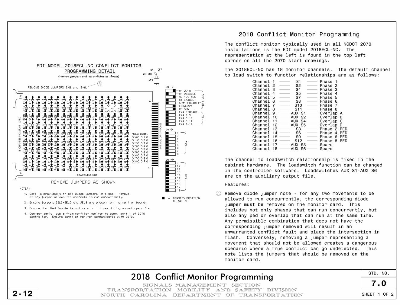
to load switch to function relationships are as follows:
The 2018ECL-NC has 18 monitor channels. The default channel
1
2
4
5
6
9
10
11
12
= DENOTES POSITION
OF SWITCH
7
8
15
16
13
14
NOTES:
of any jumper allows its channels to run concurrently.
1. Card is provided with all diode jumpers in place. Removal
FYA 1-9
FYA 3-10
FYA 5-11
FYA 7-12
RF 2010
RP DISABLE
FYA COMPACT
RF SSM
LEDguard
SF#1 POLARITY
GY ENABLE
WD 1.0 SEC
ON
FY
AO
PTI
ON
S
ON
ON
SS
MS
SM
3
17
18
(remove jumpers and set switches as shown)
PROGRAMMING DETAIL
3. Ensure that Red Enable is active at all times during normal operation.
YELLOW DISABLE
10
11
12
13
14
15
16
17
18
1
2
3
4
5
6
7
8
9
EDI MODEL 2018ECL-NC CONFLICT MONITOR
2. Ensure jumpers SEL2-SEL5 and SEL9 are present on the monitor board.
INTERN
AL
DIP S
WIT
CH
ES
REMOVE JUMPERS AS SHOWN
REMOVE DIODE JUMPERS 2-5 and 2-6.
12-16
12-15
12-14
12-13
13-16
13-15
13-14
14-16
14-15
15-16
1-16
1-15
1-14
1-13
1-12
1-11
1-1O
1-9
1-8
1-7
1-6
1-5
1-4
1-3
1-2
2-16
2-15
2-14
2-13
2-12
2-11
2-1O
2-9
2-8
2-7
2-6
2-5
2-4
2-3
3-16
3-15
3-14
3-13
3-12
3-11
3-1O
3-9
3-8
3-7
3-6
3-5
3-4
4-16
4-15
4-14
4-13
4-12
4-11
4-1O
4-9
4-8
4-7
4-6
4-5
5-16
5-15
5-14
5-13
5-12
5-11
5-1O
5-9
5-8
5-7
5-6
6-16
6-15
6-14
6-13
7-14
6-12
6-11
6-1O
6-9
6-8
6-7
7-16
7-15
7-13
7-12
7-11
7-1O
7-9
7-8
8-18
8-17
8-16
8-15
8-14
8-13
8-12
8-11
8-1O
8-9
COMPONENT SIDE
12-18
12-17
13-18
13-17
14-18
14-17
15-18
15-17
16-18
16-17
17-18
1-18
1-17
2-18
9-18
9-17
9-16
9-15
9-14
9-13
9-12
9-11
9-10
FF
A
2-17
3-17
3-18
4-17
4-18
5-17
5-18
6-17
6-18
7-17
7-18
11-12
11-13
11-14
11-15
11-16
11-17
11-18
10-11
10-12
10-13
10-14
10-15
10-16
10-17
10-18
18
CH
AN
NEL
PRO
GRA
M
CA
RD
ON OFF
SW2
WD ENABLE
controller. Ensure conflict monitor communicates with 2070.
4. Connect serial cable from conflict monitor to comm. port 1 of 2070
NORTH CAROLINA DEPARTMENT OF TRANSPORTATIONTRANSPORTATION MOBILITY AND SAFETY DIVISION
SIGNALS MANAGEMENT SECTION 7.0
Channel 17
Channel 18
Phase 2 PED
A
S4
S5
Channel 3
S7
S8
S10
S11
AUX S1
AUX S2
AUX S4
AUX S5
S3
S6
S9
S12
AUX S3
AUX S6
are on the auxiliary output file.
in the controller software. Loadswitches AUX S1-AUX S6
cabinet hardware. The loadswitch function can be changed
The channel to loadswitch relationship is fixed in the
Spare
Spare
corner on all the 2070 start drawings.
representation at the left is found in the top left
installations is the EDI model 2018ECL-NC. The
The conflict monitor typically used in all NCDOT 2070
Features:
Channel 1
Channel 2
Channel 4
Channel 5
Channel 6
Channel 7
Channel 8
Channel 9
Channel 10
Channel 11
Channel 12
Channel 13
Channel 14
Channel 15
Channel 16
Phase 1
Phase 2
Phase 3
Phase 4
Phase 5
Phase 6
Phase 7
Phase 8
Overlap A
Overlap B
Overlap C
Overlap D
Phase 4 PED
Phase 6 PED
Phase 8 PED
monitor card.
note lists the jumpers that should be removed on the
scenario where a true conflict can go undetected. This
movement that should not be allowed creates a dangerous
flash. Conversely, removing a jumper representing a
unwarranted conflict fault and place the intersection in
corresponding jumper removed will result in an
Any permissible combination that does not have the
also any ped or overlap that can run at the same time.
includes not only phases that can run concurrently, but
jumper must be removed on the monitor card. This
allowed to run concurrently, the corresponding diode
Remove diode jumper note - for any two movements to be
2-12
2018 Conflict Monitor Programming
