2018 25 paper magnifico advantages in using remote
TRANSCRIPT

1
Advantages in using remote monitoring to assess effectiveness of Cathodic
Protection in stray current affected areas I.MAGNIFICO
Automa S.r.l. – Via Casine di Paterno, snc – 60131 Ancona - Italia
ABSTRACT:
Remote monitoring introduces the possibility of performing a detailed investigation on cathodic protection, obtaining measurement every second during the whole days
and the whole weeks, catching information that manually taken measurement could lose due to their punctual characteristic.
Particularly in areas affected by stray currents, it becomes fundamental monitoring more signals at a time (DC and AC On potential, Eirfree potential) to can verify the respect of the thresholds indicated by the standards, and to check the efficiency of
all that devices that are installed to reduce interferences effects (DC and AC dischargers, drainages, etc…).
This work is focused on showing real field experiences where remote monitoring helped to evaluate correctly the cathodic protection effectiveness and highlighting
promptly failure conditions before they could cause serious corrosion issues.

2
INTRODUCTION Remote monitoring allows to make considerations about the effectiveness and
correct behavior/functioning of the cathodic protection system elements. Thanks to remote analysis it is possible to detect anomalies and malfunctions related to the damage or deterioration of the components of the cathodic protection system.
Measurements obtained with remote monitoring devices may lead to suppose, for example, that the cathodic protection rectifier has been switched off or that the anodic resistance of the impressed current anode has increased or, still, that a
damage on the unidirectional drainages has occurred and it isn’t able to interrupt the flow of the drained current when it reverses its sense of circulation.
Thanks to these considerations it will be possible to plan, in a timely manner, corrective maintenance interventions (to be combined with periodic maintenance interventions), to keep the efficiency of cathodic protection systems.
In addition, to identify anomalies or possible failures of the system elements, it is important to be aware of what the remote monitoring device are measuring.
For example, in cases with high stray currents, an analysis of the Eon potential could be not sufficient because it provides incomplete or sometimes misleading
information. Therefore, it becomes necessary to measure IRFree potential for example by performing Eoff measurement by means of coupon.
The correct choice and correct installation of the coupon is fundamental to achieve the best results, this means the necessity of choosing a coupon with appropriate shape, size, type, material and of installing it correctly with respect to the active part
of the reference electrode and the pipe. In these conditions, coupon Eoff measure can brings to zero the IR component and therefore it is possible to consider the Eoff very near to IRfree.
With this premise, it becomes necessary to have remote monitoring devices that allow to perform the coupon Eoff measurement and the best choice is a device
equipped with an integrated solid-state interrupter to control the connection between pipe and coupon.
STANDARDS REQUIREMENTS In ISO 15589-1 are specified both equipment periodicity checks and minimum routine measurements:
• Check that all cathodic protection equipment are working properly: o Impressed-Current Station
o Unidirectional Drainage Station o Connections to foreign structure (resistive or direct bond) o AC/DC decoupling devices
o Galvanic anodes o Test Stations

3
• The effectiveness of the cathodic protection shall be demonstrated in two steps:
o General assessment ON-potential measurement carried out at all or at selected test
stations.
o Detailed and comprehensive assessment OFF-potentials measurement carried out preferably at all test
stations;
when OFF pipe-to-soil potential is impossible to be carried out, OFF-potential measurements over a sufficient period of time on
external test probes or coupons are required Detailed investigations to prove the effectiveness of cathodic
protection should also be carried out in specific circumstances
Great importance must be given to the choice of the so called “selected test stations”: selected test stations may be those at the limits of the pipeline, e.g. at
isolating joints, test stations where the least negative potentials were measured during commissioning, at critical points or those shown to be representative of the cathodic protection system. Test stations associated with foreign structures should
be included, so that any changes can be detected.
In the following chapters, real cases will be shown where remote monitoring helped
in detecting in real time cathodic protection equipment failures and checking the effectiveness of cathodic protection.
PRACTICAL CASES: CP EQUIPMENT ARE WORKING?
Malfunction of cathodic protection rectifier Remote monitoring allows to detect almost in real time interruptions in the operation
of cathodic protection rectifiers, leading to a critical condition with respect to structure cathodic protection. Consequently, a maintenance intervention can be planned to prevent the pipeline
corrosion. Below an example showing the trends of the average value of:
• Eon: On potential
• I: rectifier output current
• U: rectifier working voltage
Measurements trends show that the rectifier, on 08/03/2018 has stopped its normal operation because the rectifier voltage and current are close to 0 and the value of the Eon potential becomes more positive, exceeding the threshold of the out
protection. An operator can quickly intervene to restore the rectifier correct functionality.
4
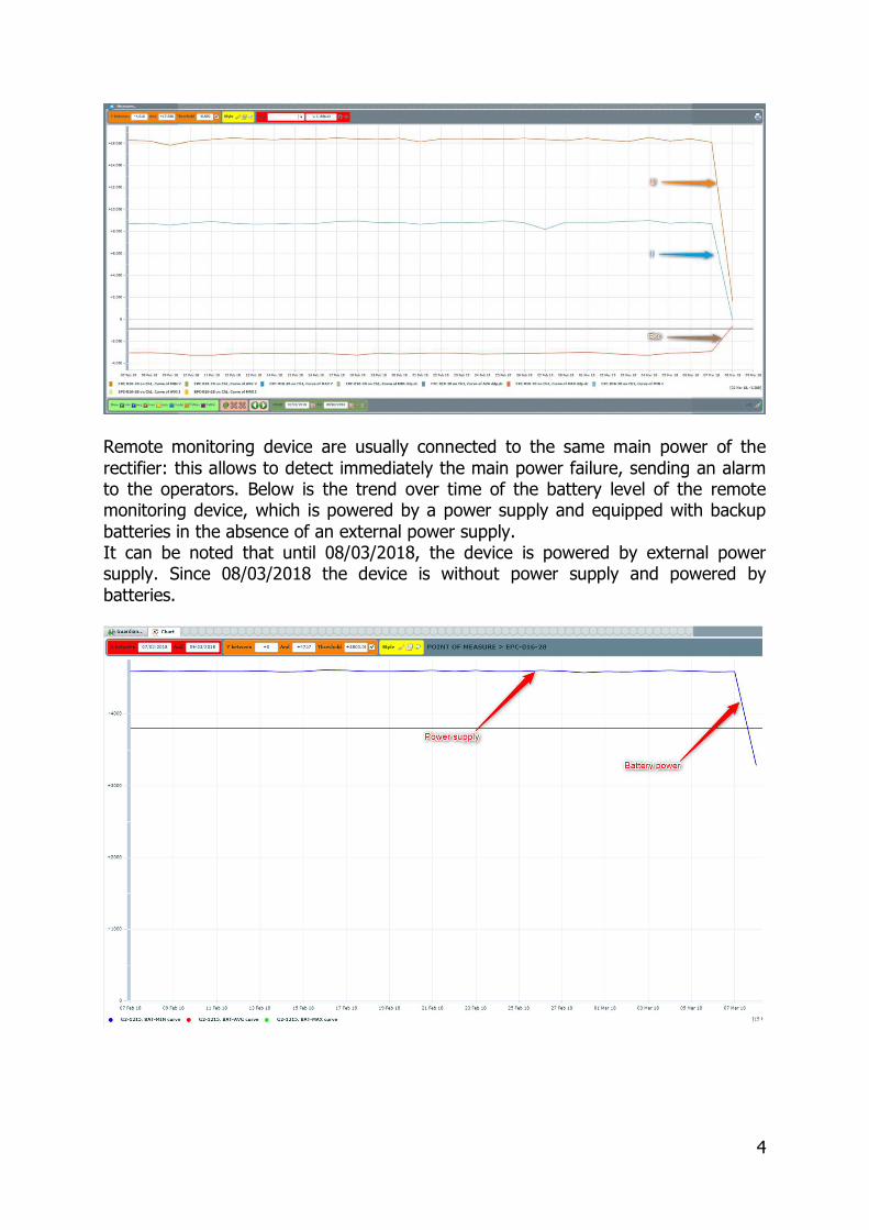
Remote monitoring device are usually connected to the same main power of the
rectifier: this allows to detect immediately the main power failure, sending an alarm to the operators. Below is the trend over time of the battery level of the remote monitoring device, which is powered by a power supply and equipped with backup
batteries in the absence of an external power supply. It can be noted that until 08/03/2018, the device is powered by external power supply. Since 08/03/2018 the device is without power supply and powered by
batteries.
5
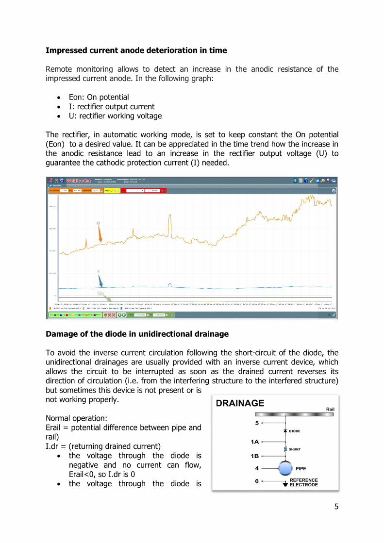
Impressed current anode deterioration in time
Remote monitoring allows to detect an increase in the anodic resistance of the impressed current anode. In the following graph:
• Eon: On potential
• I: rectifier output current • U: rectifier working voltage
The rectifier, in automatic working mode, is set to keep constant the On potential
(Eon) to a desired value. It can be appreciated in the time trend how the increase in the anodic resistance lead to an increase in the rectifier output voltage (U) to guarantee the cathodic protection current (I) needed.
Damage of the diode in unidirectional drainage
To avoid the inverse current circulation following the short-circuit of the diode, the unidirectional drainages are usually provided with an inverse current device, which
allows the circuit to be interrupted as soon as the drained current reverses its direction of circulation (i.e. from the interfering structure to the interfered structure)
but sometimes this device is not present or is not working properly.
Normal operation: Erail = potential difference between pipe and rail)
I.dr = (returning drained current) • the voltage through the diode is
negative and no current can flow, Erail<0, so I.dr is 0
• the voltage through the diode is

6
positive and the current flow, Erail (theoretically 0.7V) > 0, so I.dr >0
In case of diode failure (short circuit), drained current can move to negative values, Erail keeps negative values (but lower in absolute value) while On potential can
move to positive values due to IR component. In the following graph a 24 hour trace (second by second sampling) of:
• Eon: On potential • Erail: Pipe to rail potential
• I.dr: Drained current
It is evident the moment when the diode fails:
• Erail moves from -50V to -3V, • I.dr moves from 0A to -45A
• Eon moves from -5V CSE to +20V CSE (Full scale value) due to the anodic IR
component generated
Damaged reference electrode Thanks to remote monitoring data it is also possible to analyze and discover possible
anomalies on the reference electrodes. The following picture compares the time trends of the Eon potential of a rectifier (T/R) and a far measuring point (MP) in the same cathodic protection system.
Looking at the historical data, T/R On potential is always more negative than MP On potential. Starting from 14/12/2017 the two potentials appear with very similar values, in correspondence with an increase of T/R output current (rectifier in
automatic mode): this was due to a failure in the T/R reference electrode, that has been changed on 12/02/2018 to restore a correct condition.

7
PRACTICAL CASES: GENERAL ASSESSMENT For general assessment On potential measurement are requested, carried out at
least at the selected test stations. In areas with time variant stray currents “on site” measurement , usually performed on a short period (few minutes to few hours), may find some difficulty to catch “out
of protection” conditions, while remote monitoring, thanks to a daily measurement during all 24hrs gives the true possibilities to evaluate properly stray current effects.
Continuous monitoring: DC interference
High frequency sampling (1 measurement per second) allows to detect also short duration interference (anodic or cathodic) and the reception in the daily report of the total amount of seconds out of the settled thresholds and the number of threshold
trespassing: in this way it is possible to distinguish between isolated or negligible interferences and more risky ones.

8
Continuous monitoring: AC interference
Also AC component may vary during the day and from a day to another and monitoring in its evolution on time passing can be crucial for a correct CP evaluation.
In the example below, it is possible to see how over a one year period the AC measured on a Test Station keeps always good average values but with some
periods with continuous higher values and with a peak higher than the safety threshold of 15VAC.
PRACTICAL CASES: DETAILED ASSESSMENT
In presence of significant stray current interferences, and particularly with high insulating coatings, On potential evaluation can be very complicated due to the presence of higher IR components in the measurements. In such cases On potential
can be not only very difficult to interpret but can also mislead, as shown in the following examples. The possibility of performing instant-off measurement on coupon can give more
accurate information to evaluate cathodic protection effectiveness, and allows also to perform a continuous detailed assessment at least on the selected test stations using
the same remote monitoring system and with the same sampling frequencies used for general assessment. This leads to give great importance to the choice of the selected test stations, that if
correctly identified, can assure a better and more reliable analysis on the CP status.
Eon out of protection - Eoff protected One of the first advantages of performing a continuous coupon instant off potential
remote monitoring, is the possibility to correctly evaluate the information received and avoid false alarm conditions. It may happen that ON potential measurements due to high IR components can
show more positive values than the ones admitted in the protection criteria, forcing

9
cathodic protection technicians to take corrective actions, the most common one
being to increase cathodic protection current. Particularly with new coatings, it has become easier to incur in overprotection, so also too negative potentials should be avoided.
The following graphs show the effects of an anodic interference detected on
measuring points that lead to measure out of protection On potentials. Measuring Point 1: during the anodic interference On potential moves to positive
values, but the maximum Eoff value reached is -1,1VCSE, while the average Eoff value during the day is -1,36 VCSE.
Measuring Point 2: during the anodic interference On potential moves to out of
protection values, but the maximum Eoff value reached is -1 VCSE, while the average Eoff value during the day is -1,38 VCSE.

10
The Eoff measure on coupon shows in both cases the presence of an already strong overprotection condition, so demonstrating that not only it is not necessary to
increase cathodic protection current, but that should be even evaluate the possibility of reducing it.
Evaluation of the duration of out of protection conditions It is also very important to have the possibility, not only of evaluating the presence
or not of real out of protection conditions, but also knowing the duration of the out of protection periods.
In the example below the day by day trend of Eon and Eoff potentials on a measuring point shows for both the presence of maximum daily values more positive
than -0,85V CSE
In the following table are shown the daily data of the measuring point:
• ddp.dc=Eon;
• ddp.pbt=Eoff; • TFSMax=number of seconds during the 24hrs above -0,850 VCSE;
• NFSMax=number of -0,850 VCSE threshold trespassing during the 24hrs

11
Going deeper into the information received and analyzing the duration of the out of
protection periods comes out the differences between Eon and Eoff: for example, on April 6th in presence of more than 2 hours (7339 seconds) of Eon out of protection, Eoff presents a total amount of only 40 seconds out of protection.
Evaluation on extended CP systems
In presence of very extended cathodic protection systems, it is possible to meet very different soil and interferences conditions along the whole pipeline, for example very
significant differences in soil resistivity. In the example below on a 150 Km CP system there are two measuring points with different soil resistivity, but CP technicians are using the -0,850 VCSE threshold for
both to meet protection criteria which results in strong overprotection on MP1:
MP1 (Low resistivity, ρ < 100 Ω·m)
MP2 (High resistivity, 100 < ρ < 1000 Ω·m)
DATE M.U. MIN AVG MAX MIN AVG MAX
06/04/2018
Eon -1,792 -1,754 -1,580 -0,956 -0,917 -0,884
Eoff -1,458 -1,438 -1,410 -0,900 -0,879 -0,860
mI.p +9,800 +17,270 +19,640 +0,080 +0,296 +0,460
05/04/2018
Eon -1,798 -1,755 -1,718 -0,948 -0,917 -0,888
Eoff -1,452 -1,438 -1,412 -0,898 -0,879 -0,868
mI.p +15,380 +17,309 +19,080 +0,040 +0,295 +0,560
04/04/2018
Eon -2,804 -1,758 -1,680 -1,138 -0,921 -0,894
Eoff -1,468 -1,438 -1,412 -0,950 -0,883 -0,868
mI.p +13,960 +17,409 +80,800 +0,000 +0,298 +1,880
03/04/2018
Eon -1,798 -1,762 -1,720 -0,968 -0,926 -0,894
Eoff -1,454 -1,439 -1,410 -0,906 -0,887 -0,870
mI.p +15,340 +17,609 +20,240 +0,080 +0,302 +0,520
02/04/2018
Eon -1,798 -1,766 -1,724 -0,966 -0,932 -0,898
Eoff -1,454 -1,441 -1,416 -0,912 -0,893 -0,876
mI.p +15,540 +17,588 +19,060 +0,060 +0,309 +0,580
01/04/2018
Eon -1,788 -1,767 -1,730 -0,960 -0,933 -0,906
Eoff -1,454 -1,441 -1,418 -0,914 -0,893 -0,868
mI.p +15,720 +17,567 +18,760 +0,040 +0,307 +0,500

12
In the next weeks the technicians will start decreasing the CP current in the system
to meet the -0,750 VCSE on MP2 as required by ISO 15589-1 and so possibly obtaining improved conditions also on MP1 with respect to overprotection issue.
Protection achieved by passivity or immunity: PH considerations
It is known that cathodic protection current flowing into the metal surface of the pipeline can modify chemical characteristics in the surrounding soil. PH level can have a significant rule particularly with respect to corrosion mechanism
in presence of stray currents:
• high PH level can favorite the creation of a passive film on the metal surface,
bringing the capacity of better reaction in presence of anodic currents (protection achieved by passivity), since the passive film must be broken up
before starting again the corrosion process on the metal; • low PH level means no passive film on metal surface (protection achieved by
immunity), so an anodic current immediately starts the corrosion process. To obtain a local PH increase (unless of being in presence of specific
soil/environment unfavorable conditions) a sufficient current density is needed. For this reason it is easier to reach higher PH values in presence of high insulating coatings (less total amount of current is needed to produce high current densities)
with respect to older coatings where very higher current is needed for obtaining high current densities. Following graphs show the mutual evolution of Eoff (coupon instant-off potential)
and Eon (On potential) on two different measuring points and give an understand of the PH evolution where is possible to evaluate it .
In the first graph Eoff potential is very stable and with very small variations respect to On potential: in this case, it can be assumed that an increased PH has allowed the formation of a passive film on the metal surface and that protection has been
achieved by passivity.
The second graph shows the evolution of an Off potential that changes significantly with respect to On potential variations: in this case, it can be assumed that no

13
increase in PH has been reached on the metal surface and that protection has been
achieved by immunity.
While in the first case a passive film has been formed on the metallic surface (Eoff is
about -1,2 VCSE), thus protecting from corrosion during short duration anodic interferences, in the second case no enough current is reaching the metallic surface
of the coupon (Eoff is about -0,85 VCSE) thus meaning an immediate corrosion process activation as just as current moves anodic.
CONCLUSIONS Remote monitoring helps people involved in cathodic protection analysis to better
evaluate the operating status of cathodic protection and cathodic protection devices (i.e.: rectifiers, drainages, reference electrodes, etc...)
The possibility of comparing On and Off potential and polarization current, can lead to perform very significant analysis, such as stray current evaluation, cathodic protection effectiveness and even some consideration on PH evolution.
Performing instant off potential on coupon allows remote monitoring to move from effectiveness general assessment to detailed assessment at least on all the selected
test stations. In this aspect, the choice of the selected test stations assume a very important relevance to obtain the best information.
In this way, resources and efforts can be focused on the real needs. Possible corrosion threats can be easier identified and investigated.