2017 qx30 nm sg -...
TRANSCRIPT

i
NMTI2017QX30-ILT
CREATED JUNE, 2016

ii
This book is designed for instructional useonly for authorized Nissan North America, Inc. and Nissan dealer personnel. For additional information contact:
Nissan North America, Inc.Product, Service, and Technical TrainingP.O. Box 685001Franklin, TN 37068
© 2016 Nissan North America, Inc.
All rights reserved. No part of this publication may be reproduced in any form without the prior written permission of the publisher.
Printed in U.S.A.
First Printing: June, 2016
Product, Service, and Technical Training
Nissan North America, Inc. reserves the right to alter specifications or methods at any time.
Product, Service, and Technical
Nissan North America, Inc.
Training Department
This manual uses post consumer recycled fibers

2017 INFINITI QX30 NEW MODEL TRAININGTABLE OF CONTENTS
Course Objectives
Course Procedures: 2017 Infiniti QX30 New Model Training
SECTION 1: Text
Introduction ................................................................................................................................ 7
General Information.................................................................................................................. 8
Vehicle Dimensions .......................................................................................................................... 8
Model Variation....................................................................................................................................9
Vehicle Information Number .............................................................................................................9
SIS Code ...........................................................................................................................................10
VIN Locations....................................................................................................................................10
Data Stickers.....................................................................................................................................10
Engine Codes ...................................................................................................................................10
Access Points ...................................................................................................................................10
Jacking Points ...................................................................................................................................11
Fuel Requirements ...........................................................................................................................11
Battery Charging ..............................................................................................................................11
Main and Auxiliary Battery Replacement ....................................................................................12
Jump Start Procedure .....................................................................................................................12
Towing ................................................................................................................................................12
PDI, Service, and Maintenance........................................................................................... 13
Pre-delivery Inspection .................................................................................................................. 13
Service and Maintenance.............................................................................................................. 14
Fluid Specifications .........................................................................................................................15
Coolant Draining ..............................................................................................................................16
Exhaust Pipe Repair ........................................................................................................................17
Programming and Configuration Processes..............................................................................18
Electrical and Power Control............................................................................................... 19
iii
Body Control Module...................................................................................................................... 19
Electronic Ignition Switch .............................................................................................................. 20
Batteries and Alternator ................................................................................................................. 20
Energy Management System ........................................................................................................ 21
Engine ON Energy Management ................................................................................................. 22
Engine OFF Energy Management................................................................................................ 22
Stop/Start Energy Management .................................................................................................. 23
Stop/Start Cycle .............................................................................................................................. 24
Network Architecture............................................................................................................. 25
Network Overview ........................................................................................................................... 25
Topology ............................................................................................................................................ 25
Network Divisions ............................................................................................................................ 28
Gateways........................................................................................................................................... 28
OBD Socket ..................................................................................................................................... 28
Potential Distributors ...................................................................................................................... 29
1.6L & 2.0L Turbo Engine ...................................................................................................... 31
Overview............................................................................................................................................ 31
Specifications ................................................................................................................................... 32
Service Point..................................................................................................................................... 32
Component Locations .................................................................................................................... 33
Crank Pulley ...................................................................................................................................... 34
Camshaft Timing .............................................................................................................................. 34
Crankshaft Position ......................................................................................................................... 35
Stop/Start System.................................................................................................................. 31
Twin Battery Management............................................................................................................. 37
GE7F30A Dual Clutch Transaxle......................................................................................... 38
Overview............................................................................................................................................ 38
Gear Ratios ....................................................................................................................................... 38
Main Components ........................................................................................................................... 39
Gear Train Operation...................................................................................................................... 39
iv
Gear Train Construction.................................................................................................................40
Dual Clutch Operation ....................................................................................................................41
Dual Clutch Construction...............................................................................................................41
Power Flow........................................................................................................................................42
Reverse Gear Operation ................................................................................................................44
Control Valve Assembly..................................................................................................................45
Shift Selector ....................................................................................................................................45
Gear Shift...........................................................................................................................................46
Oil Supply ..........................................................................................................................................46
Transaxle Cooling.............................................................................................................................47
Park Pawl ...........................................................................................................................................47
Maintenance......................................................................................................................................48
Diagnosis and Repair ......................................................................................................................48
All-wheel Drive ........................................................................................................................ 49
System Integration ...........................................................................................................................50
AWD Control Unit............................................................................................................................50
AWD Solenoid Valve.......................................................................................................................50
Oil Pump ............................................................................................................................................50
Suspension............................................................................................................................... 51
Front Suspension .............................................................................................................................52
Rear Suspension..............................................................................................................................53
Alignment Angles .............................................................................................................................54
Tire Pressure Monitoring System ...................................................................................... 55
System Operation ............................................................................................................................55
TPMS Reset ......................................................................................................................................55
Sensor ID Registration....................................................................................................................56
Auto-learn ..........................................................................................................................................56
Service Points ...................................................................................................................................56
Tires ............................................................................................................................................ 57
Puncture Repair................................................................................................................................57
v

Winter Tires....................................................................................................................................... 57
Snow Chains .................................................................................................................................... 57
Wheels ....................................................................................................................................... 58
Accent Wheels................................................................................................................................. 58
Brake System........................................................................................................................... 60
Brake Control System ........................................................................................................... 61
System Overview............................................................................................................................. 61
Hill Start Assist................................................................................................................................. 61
Forward Emergency Braking......................................................................................................... 62
Other Functionality .......................................................................................................................... 63
Electric Parking Brake........................................................................................................... 66
Parking Brake Actuator .................................................................................................................. 66
System Operation............................................................................................................................ 67
Emergency Mode............................................................................................................................. 67
Fail Safe ............................................................................................................................................. 67
Service Points................................................................................................................................... 67
Steering ..................................................................................................................................... 68
Fail Safe ............................................................................................................................................. 69
Workshop Mode .............................................................................................................................. 69
EPS Control Unit Replacement.................................................................................................... 69
Service Points................................................................................................................................... 69
Sonar System and Park Assist ........................................................................................... 70
System Types ................................................................................................................................... 70
Parking Sensor Settings ................................................................................................................ 71
Sonar Ranges................................................................................................................................... 72
Park Assist......................................................................................................................................... 73
System Diagnosis............................................................................................................................ 73
Sonar Control Unit Replacement................................................................................................. 73
Automatic Speed Control ..................................................................................................... 74
Intelligent Cruise Control ..................................................................................................... 75
vi

Long Range Radar Alignment .......................................................................................................75
Driver Assistance Systems................................................................................................... 76
Components......................................................................................................................................76
Lane Departure Warning................................................................................................................78
Blind Spot Warning.........................................................................................................................78
Front Camera Adjustment ..............................................................................................................79
Rearview Camera.............................................................................................................................80
Restraints.................................................................................................................................. 81
Air Bag Module.................................................................................................................................82
Air Bag Control Unit Replacement ..............................................................................................82
Crash/Impact Sensors ....................................................................................................................82
Pyrofuse..............................................................................................................................................83
Front Passenger Seat Occupancy Detection ...........................................................................84
Seat Belts ..........................................................................................................................................85
Air Bags..............................................................................................................................................86
Emergency Call ................................................................................................................................86
HVAC .......................................................................................................................................... 38
Refrigerant Circuit............................................................................................................................87
Control Panel ....................................................................................................................................89
Air Conditioning Filter .....................................................................................................................90
Air Quality Sensor ............................................................................................................................90
Outside Air Temperature................................................................................................................91
Interior Temperature Sensor..........................................................................................................91
Sunload Sensor................................................................................................................................92
Eco Stop/Start Function.................................................................................................................92
Auto Air Recirculation Mode .........................................................................................................92
Diagnosis ...........................................................................................................................................92
Driver Controls......................................................................................................................... 93
Steering Wheel Combination Switch..........................................................................................94
Central Switch Panel.......................................................................................................................95
vii

Rotary Lighting Switch ................................................................................................................... 95
Instrument Panel .................................................................................................................... 96
General Layout ................................................................................................................................. 96
Speedometer Types........................................................................................................................ 96
Warning and Information Symbols .............................................................................................. 97
Service Point..................................................................................................................................... 97
Vehicle Information Display ................................................................................................ 98
Door Control............................................................................................................................. 99
Door Modules .................................................................................................................................100
Door Switches................................................................................................................................101
Lighting.................................................................................................................................... 102
Halogen Headlamp System ........................................................................................................102
LED Headlamp System ................................................................................................................103
Headlamp Control Unit.................................................................................................................104
LED Headlamp Control Module .................................................................................................104
Auto Lights ......................................................................................................................................105
Lighting Circuits.............................................................................................................................105
Active Adaptive Front Lighting System.....................................................................................107
High Beam Assist System...........................................................................................................107
Bulb Replacement .........................................................................................................................108
Wipers ...................................................................................................................................... 109
Front Wipers...................................................................................................................................109
Rear Wiper......................................................................................................................................110
Spray Nozzle Hose Heater ..........................................................................................................111
Wiper Blade Replacement ..........................................................................................................111
Seats......................................................................................................................................... 112
Seat Position and Memory ..........................................................................................................113
Seat Control Modules...................................................................................................................114
Seat Heaters...................................................................................................................................114
viii

Security.................................................................................................................................... 115
Component Locations.................................................................................................................. 115
Door Locks ..................................................................................................................................... 116
Fuel Lid Assembly ......................................................................................................................... 118
Emergency Fuel Lid Lock Release............................................................................................ 119
Emergency Tailgate Release ...................................................................................................... 119
Door Lock Key Control ................................................................................................................ 120
Emergency Mechanical Key........................................................................................................ 120
Key Battery Replacement............................................................................................................ 120
Central Locking System .............................................................................................................. 121
Intelligent Key System.................................................................................................................. 123
Immobilizer ...................................................................................................................................... 124
Vehicle Alarm ................................................................................................................................. 124
Glass and Windows.............................................................................................................. 125
Windshield Glass.......................................................................................................................... 125
Interior Mirror.................................................................................................................................. 125
Door Mirrors ................................................................................................................................... 126
Power Windows............................................................................................................................ 127
Heated Rear Glass ....................................................................................................................... 129
Heated Washer System .............................................................................................................. 129
Paint ......................................................................................................................................... 130
Body.......................................................................................................................................... 130
Noise, Vibration, and Harshness (NVH) .................................................................................. 131
Styling .............................................................................................................................................. 132
Emblem............................................................................................................................................ 133
Rear Spoiler.................................................................................................................................... 133
Kick Plate ........................................................................................................................................ 134
Back Door....................................................................................................................................... 134
Audio, Visual, and Navigation ........................................................................................... 135
InTouch............................................................................................................................................ 135
ix
Display Control Unit ......................................................................................................................136
NAVI Control Unit ..........................................................................................................................137
AV Control Unit ..............................................................................................................................137
External Data Input Box (SD Card)............................................................................................138
External Data Input Box (USB) ...................................................................................................138
Active Noise Control Unit ............................................................................................................138
Active Noise Cancellation............................................................................................................139
Active Sound Enhancement........................................................................................................139
On-board Diagnosis .....................................................................................................................140
Around View Monitor ....................................................................................................................142
Navigation System.........................................................................................................................142
SECTION 2: ModulesSign-off sheetModule 1: QX30 DiscoveryModule 2: CAN & Network ArchitectureModule 3: Energy Management SystemModule 4: DCT Fluid Level CheckModule 5: Restraint SystemModule 6: AWD FamiliarizationModule 7: QX30 Intelligent Key Entry SystemModule 8: DAS and Front Camera FamiliarizationModule 9: Brake ServiceModule 10: Tire Pressure Monitoring
SECTION 3: Notes
x

COURSE OBJECTIVES
Upon completion of this training program, given a 2017 Infiniti QX30, you will be able to:• Explain the function and operation of the features and controls of the 2017
Infiniti QX30.• Explain the CAN architecture and CAN Potential Distributor Electrical Connec-
tor function.• Identify the components used by the energy management system and their
functions.• Correctly perform transaxle fluid level inspection, interpret the results, and
determine if the level should be adjusted.• Identify additional service required after replacing the Air Bag Diagnosis Sen-
sor and the Occupant Classification System control unit.• Monitor system functions of the AWD system using CONSULT, and identify
additional service when replacing the control unit or components.
• Identify the various components of the Intelligent Key Entry System, their functions, locations, and special service requirements.
• Explain the function and service requirements of the front camera unit.• Explain the operation of the electronic parking brake and unique service
brake features.• Explain the operation of the TPMS system, reset the TPMS reference pressure
values, identify the ID numbers for each tire pressure sensor, and write the ID numbers to the low tire pressure warning control unit.
• Use CONSULT to check components and monitor the operation of the Evapo-rative Emissions System (EVAP).
xi

COURSE PROCEDURES: 2017 INFINITI QX30 NEW MODEL TRAINING
Infiniti Competency Based Training:
Class starts promptly at 9:00 AM. Please be in your seat and ready to begin at 9:00 AM. Silence your cell phone.
Class ends when all the modules on your Course Sign Off sheet are initialed by the instructor. Nissan and Infiniti design courses so that most technicians should be able to complete the mod-ules in the time provided for the course.
Experienced technicians should be able to complete all the modules in the two days scheduled for the class. If you are unable to complete the course requirements in the time provided, the instructor will discuss options available for you to receive course credit. You are responsible for learning how to perform the diagnostic procedures featured in this course. It is important that you take as much time as you need to learn the skills presented in the course worksheets. If you cannot complete the modules in the time provided, the instructor will work with you and your dealership to help you complete the course.
Text:
The text contains information relating the features and technology found on the 2017 Infiniti QX30. Some of the questions in the worksheets can be answered using the text. You will not have the opportunity to read the text thoroughly during this class, so please save the text as a resource to answer questions about the technology and systems unique to this vehicle.
Modules: 1. Begin the module by reading the Objective, Relevance, Resources, and Skill Check infor-
mation on the first page.
2. Contact the instructor if you cannot locate the resources or if the vehicle has a problem that seems unrelated to the module. (ie: dead battery)
3. You will probably be working with one or more technicians. Follow these basic guidelines to work effectively as a team:
- Take responsibility to understand and perform each step of the worksheet yourself.
- If using CONSULT-III + or other tools, be sure to check on-screen results yourself and hand the tool to the other technician(s) so they can also confirm test results.
- If you are expected to test a component or remove and inspect parts, perform those pro-cedures yourself and give the same opportunity to your co-workers.
- Be patient. Everyone works at different speeds. You are responsible to perform each module objective – and you are responsible to insure the technician(s) working with you have also completed the ‘Skill Check’.
xii

- Complete all the questions on the worksheet. In some cases, the worksheet may give you the opportunity to skip steps, for example – you may not need to follow instructions for booting CONSULT-III + if you are already confident using the tool. If your co-workers wish to complete those instructions, be patient as they complete those steps.
- Treat the training center vehicles as if they were customers’ cars. However, if you damage anything while performing the module, tell the instructor right away. Some components such as trim pieces or wire connections may break during testing. We expect these occasional problems and need to know about them as soon as they occur.
- Return the vehicle to the condition it should be in for the next team of technicians to com-plete the module. For example: Reset bugs if applicable, return tools to the bench or tool box, and straighten up the work area.
- Contact the instructor when you have completed the module and are confident you can perform the ‘Skill Check’ noted on the first page. Expect the instructor to review your worksheet and confirm that you have completed the objective. Tell the instructor if you feel you need more practice. If possible, the instructor will provide you with additional information or give you the opportunity to work on the vehicle later in the day.
Resources:
Resources may include ASIST, CONSULT-III +, the ESM, Special Service Tools (SST), hand tools, DVOMs, and vehicle parts. If the ASIST terminal is not working properly or is not updated, contact the instructor.
Monitor the battery power for CONSULT-III + and connect it to the charger as needed. For this course we expect you to be comfortable using CONSULT-III + for testing the CAN system and for accessing Self Diagnosis, Data Monitor, Active Test, and Work Support. Contact the instruc-tor if you are not familiar with using these applications.
Contact the instructor if you have questions about using the listed resources or there is a prob-lem with any of the resources you will need to complete the module.
PowerPoint Notes:
The PowerPoint slides are reprinted in your Technician Workbook. Refer to the Notes section of the book to follow the classroom discussion. The classroom discussion highlights information you will practice during workshop modules. Make notes and ask questions during the discussion and you will learn information that will help you complete the worksheet objectives.
xiii

Technician Creed and Code of Repair
This vehicle is the personal property of the customer.
The customer’s desire is: I correctly service / repair their vehicle today. My desire is: He / She returns to my place of business for additional service and repairs unrelated to today’s visit.
It is my choice regarding the quality of repair I make today.
I will do all I can to gain the customer’s trust while servicing and repairing their vehicle.
ATTITUDE IS EVERYTHING!I N F I N I T I
xiv

TEXT

QX30 New Model Training

QX30 New Model TrainingContentsIntroduction 7General Information 8
Vehicle dimensions 8Vehicle variation 9Vehicle information number 9SIS code (Infiniti model variation code) 10VIN locations 10Data stickers 10Engine codes 10
101111111212
Access points Jacking points Fuel requirementsBattery charging Main and auxiliary battery replacement Jump start procedure Towing 12
PDI, Service and Maintenance 13Pre delivery inspection 13Service and maintenance 14Fluid specifications 15Coolant draining 16Exhaust pipe repair 17Programming and configuration processes 18
Electric and Power Control 19Body control module 19Electronic ignition switch 20Batteries and alternator 20Energy management system 21Engine ON energy management 22Engine OFF energy management 22Stop/start energy management 23Stop/start cycle 24
Network Architecture 252525282828
Network overview TopologyNetwork divisions GatewaysOBD socket Potential distributors 29
1.6 L & 2.0L Turbo Engine 3131323233343435
Overview Specifications Service point Component locations Crank pulley Camshaft timing Crankshaft position
QX30 New Model TrainingStop/Start System 36
Twin battery management 37
GE7F30A Dual Clutch Transmission 3838383939404141424445454646474748
OverviewGear ratios Main components Gear train operation Gear train construction Dual clutch operation Dual clutch construction Power flow Reverse gear operation Control valve assembly Shift selector Gear shift Oil supply Transmission cooling Park pawl Maintenance Diagnosis and repair
48All Wheel Drive 49
505050
System integration AWD control unit AWD solenoid valve Oil pump 50
Suspension 515253
Front suspension Rear suspension Alignment angles 54
Tire Pressure Monitoring System 5555555656
System operation TPMS reset Sensor ID registration Auto-learnService points 56
Tires 575757
Puncture repair Winter tires Snow chains 57
Wheels 5858
60Accent wheels
Brake System Brake Control System 61
616162
System overview Hill start assist Forward emergency braking Other functionality 63
QX30 New Model TrainingElectric Parking brake 66
Parking brake actuator 66System operation 67Emergency mode 67Fail safe 67Service points 67
Steering 68Fail safe 69Workshop mode 69EPS control unit replacement 69Service points 69
Sonar System and Park Assist 70System types 70Parking sensor settings 71Sonar ranges 72Park assist 73System diagnosis 73Sonar control unit replacement 73
Automatic Speed Control 74Intelligent Cruise Control 75
Long range radar alignment 75Driver Assistance Systems 76
76787879
ComponentsLane departure warning Blind spot warningFront camera adjustment Rearview camera 80
Restraints 8182828283
Air bag module Air bag control unit replacement Crash/impact sensorsPyrofuse
848586
Fr. passenger seat occupancy detectionSeat belts Air bags Emergency call 86
HVAC 8787899090919192929292
Refrigerant circuit Control panel Air conditioning filter Air quality sensor Outside air temperatureInterior temperature sensor Sunload sensor Eco stop start function Auto air recirculation modeDiagnosis

QX30 New Model TrainingDriver Controls 93
Steering wheel combination switch 94Central switch panel 95Rotary lighting switch 95
Instrument Panel 96General layout 96Speedometer types 96Warning and information symbols 97Service point 97
Vehicle Information Display 98Door Control 99
Door modules 100Door switches 101
Lighting 102102103104104105105107107
Halogen headlamp system LED headlamp system Headlamp control unit LED headlamp control module Auto lightsLighting circuits Active adaptive front lighting system High beam assist system Bulb replacement 108
Wipers 109109110111
Front wipers Rear wiper Spray nozzle hose heater Wiper blade replacement 111
Seats 112113114
Seat position and memory Seat control modules Seat heaters 114
Security 115115116118119119120120120121123124
Component locations Door locks Fuel lid assembly Emergency fuel lid lock release Emergency tailgate release Door lock key control Emergency mechanical key Key battery replacement Central locking system Intelligent key system ImmobilizerVehicle alarm 124
Glass and Windows 125125125126127129
Windshield glassInterior mirror Door mirrors Power windows Heated rear glass Heated washer system 129

QX30 New Model TrainingPaint 130Body 130
Noise, vibration and harshness (NVH) 131Styling 132Emblem 133Rear spoiler 133Kicking plate 134Back door 134
Audio Visual and Navigation 135InTouch 135Display control unit 136NAVI control unit 137AV control unit 137External data input box (SD Card) 138External data input box (USB) 138Active noise control unit 138Active noise cancellation 139Active sound enhancement 139On-board diagnosis 140Around view monitor 142Navigation system 142

7
Training documentation is for learning purposes only. Always refer to
the service manual for the most up to date information.
QX30 New Model Training
IntroductionInfiniti revealed its QX30 active compact during its press conference at the 2015 Frankfurt Motor Show. Representing Infiniti’s first entry into the fast-growing premium compact segment, the QX30 will play an important role in helping the company realize its plans for global growth.
The QX30 challenges convention with its bold character and daring shape and stays true to the signature design cues from the original 2013 concept. QX30 offers exceptional ride and handling thanks to the versatile dimensions, confident dynamics and intuitive technologies.
In November 2015 the QX30 AWD premium active crossover made its simultaneous global debut at the 2015 Los Angeles and Guangzhou international motor shows. QX30 AWD offers an elevated ride height, confidence-inspiring handling, a ‘go-anywhere’ attitude and comes available with an intelligent all-wheel drive system.

General Information Vehicle Dimensions
8
Front Overhang Wheelbase Rear Overhang
Overall Length
Overall Width
Overall Height
Length Width Height Front Overhang Wheelbase Rear Overhang Ground Clearance
QX30 Base/Premium
QX30 Sport
QX30 AWD
106.3106.3
106.3
82.01
82.0182.01
59.45
58.0360.24
35.98
35.9835.98
32.01
32.0132.01
174.21
174.21
174.21
6.77
6.10
7.95
All dimensions expressed in inches.
QX30 New Model Training

9
Destination Body Engine Axle Handle Transmission Grade Model
USA
4 doorhatchback
2.0L turboengine
2WD LHD 7DCT
Base DEBALPL-UUA
Leather DEBALQL-UUA
Premium DEBALRL-UUA
Sport DEBALTL-UUA
Canada
Base DEBALPL-UUA
Leather DEBALQL-UNA
Premium DEBALRL-UNA
Sport DEBALTL-UNA
Mexico
1.6L turboengine Base DECALPL-UJH
2.0L turboengine
Premium DEBALRL-UJA
Sport DEBALTL-UJA
AWD MODELS
Destination Body Engine Axle Handle Transmission Grade Model
USA4 door
hatchback2.0L turbo
engine AWD LHD 7DCT
Base DEBNLXL-UUA
Premium DEBNLYL-UUA
CanadaBase DEBNLXL-UNA
Premium DEBNLYL-UNA
Model VariationFWD MODELS VEHICLE IDENTIFICATION NUMBER ARRANGEMENT
QX30 New Model Training
10
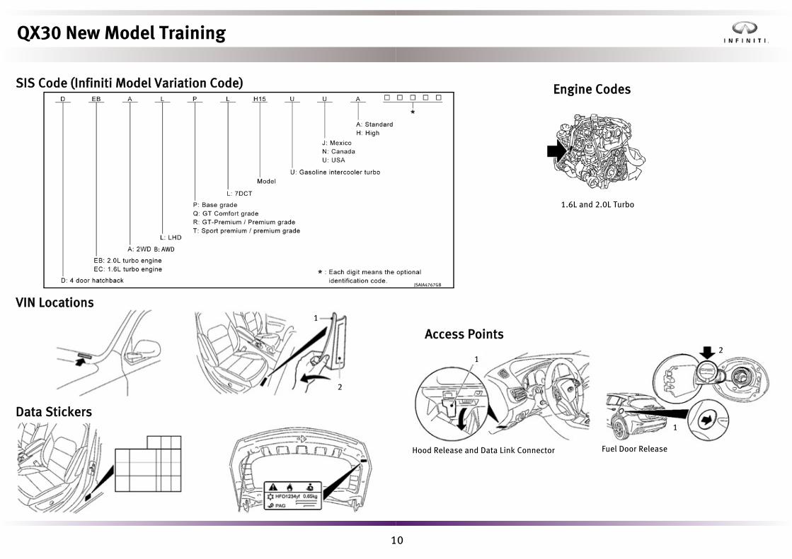
SIS Code (Infiniti Model Variation Code)
VIN Locations
Data Stickers
Engine Codes
1.6L and 2.0L Turbo
1
2
Access Points
Fuel Door ReleaseHood Release and Data Link Connector
1
1
2
JSAIA4767GB
B: AWD
QX30 New Model Training

11
Jacking Points
Front Rear
Fuel RequirementsUnleaded premium fuel (minimum 91 AKI/95 RON).Unleaded regular fuel (minimum 89 AKI/91 RON) can be used temporarily with the following limitations:
• Have the fuel tank filled only partially with unleaded regular, and fillup with unleaded premium as soon as possible.
• Avoid full throttle driving and abrupt acceleration.
Use unleaded premium for maximum vehicle performance.
Battery ChargingCurrent draw with the ignition on can reach in excess of 35 amps, and a conventional battery charger may not be sufficient to handle the energy requirements. When working on the vehicle with the ignition on/engine, off it is recommended that a battery charger capable of supplying up to 50 amps of current should be connected to the main vehicle battery.
QX30 New Model Training

12
Main and Auxiliary Battery ReplacementQX30 uses VRLA (valve-regulated lead-acid) batteries with AGM (absorbed glass mat) technology in support of the stop/start function.Do not use any other type of battery, as this may cause early deterioration of the battery or a malfunction of the stop/start system.
Jump Start ProcedureIn the unlikely event of excessive battery discharge or failure, connect the jump start cables in the sequence shown. Disconnect in reverse order when safe to do so.
1
3
4
2
TowingTowing methods are as follows: Front Wheel Drive All-wheel Drive
QX30 New Model Training

13
Service ReminderReset the service reminder using the following methods. With CONSULT-III plus:
1. Open METER/M&A and select Active Test.2. Select Confirmation of General Maintenance if you wish to see the
remaining time between services.3. Select Reset General Maintenance once a service has been completed on
the vehicle.
Without CONSULT-III plus (for PDI only):1. Ensure the ignition key is set to the accessory position 1 and trip
information is displayed on the instrument panel vehicle informationdisplay.
2. Press and hold the steering wheel RH phone button followed by the LH OKbutton simultaneously for five seconds until the service and self diagnosishidden screen appears.
3. Scroll through the sub menu options and select Maintenance to obtainservice related data and reset the service interval.
NOTE: If the odometer reads below 155 miles the service reminder can be set in the information display as at PDI. CONSULT must be used to reset service reminder at odometer readings above 155 miles
When resetting the service interval via the vehicle information display, you must select the correct oil type for the engine fitted to the vehicle.
Engine oil code for 2.0L: 229.5
• No transport mode release process is required.• Check vehicle is set to default settings or customer preferences via the
combination meter display menu and CONSULT-III plus.• Check and adjust tire pressures and then manually reset the TPMS
benchmark monitoring pressure via the steering wheel controls and thevehicle information display menu to ensure correct TPMS operation.
• Observe vehicle battery maintenance and test procedures in line with theAPRM.
• SIR volumes 183 and 184 provide details on performing proper PDI.
QX30 New Model Training
PDI, Service and MaintenancePre-delivery InspectionCarry out the pre-delivery inspection according to the PDI document found in the vehicle packet and guidelines outlined in the Infiniti Assurance Products Resource Manual (APRM). QX30 specific points are as follows:
14
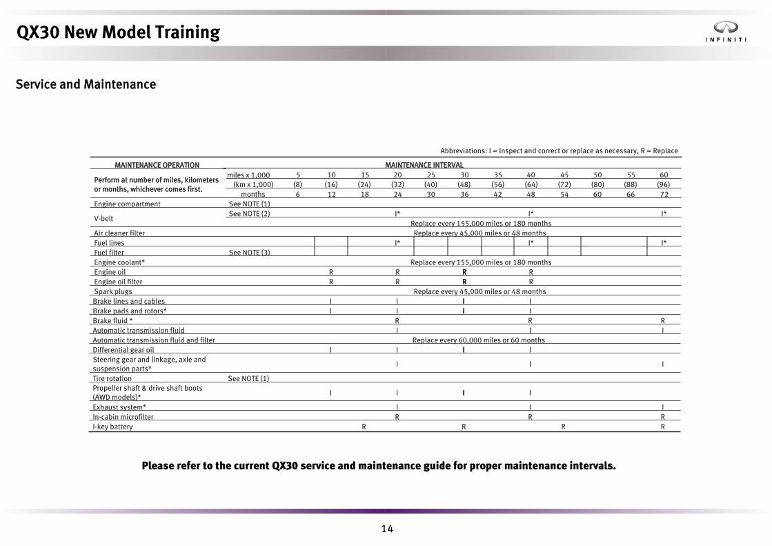
Service and Maintenance
Abbreviations: I = Inspect and correct or replace as necessary, R = Replace
MAINTENANCE OPERATION MAINTENANCE INTERVAL
Perform at number of miles, kilometers or months, whichever comes first.
5 10 15 20 25 30 35 40 45 50 55 60(km x 1,000) (8) (16) (24) (32) (40) (48) (56) (64) (72) (80) (88) (96)
months 6 12 18 24 30 36 42 48 54 60 66 72Engine compartment See NOTE (1)
V-beltSee NOTE (2) I* I* I*
Replace every 155,000 miles or 180 monthsAir cleaner filter Replace every 45,000 miles or 48 monthsFuel lines I* I* I*Fuel filter See NOTE (3)Engine coolant* Replace every 155,000 miles or 180 monthsEngine oil R R RRR REngine oil filter R R RRR RSpark plugs Replace every 45,000 miles or 48 months
miles x 1,000
Brake lines and cables I I III IBrake pads and rotors* I I III IBrake fluid * R R RAutomatic transmission fluid I I IAutomatic transmission fluid and filter Replace every 60,000 miles or 60 monthsDifferential gear oil I I III ISteering gear and linkage, axle and suspension parts*
I I I
Tire rotation See NOTE (1)Propeller shaft & drive shaft boots (AWD models)*
I I III I
Exhaust system* I I IIn-cabin microfilter R R RI-key battery R R R R
QX30 New Model Training
Please refer to the current QX30 service and maintenance guide for proper maintenance intervals.
15
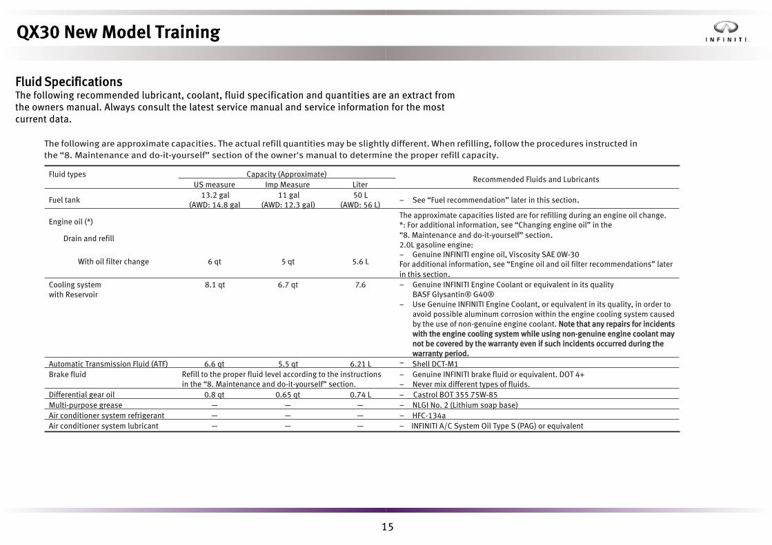
Fluid SpecificationsThe following recommended lubricant, coolant, fluid specification and quantities are an extract from the owners manual. Always consult the latest service manual and service information for the most current data.
The following are approximate capacities. The actual refill quantities may be slightly different. When refilling, follow the procedures instructed in the “8. Maintenance and do-it-yourself” section of the owner's manual to determine the proper refill capacity.
Fluid types Capacity (Approximate)Recommended Fluids and Lubricants
US measure Imp Measure Liter
Fuel tank13.2 gal
(AWD: 14.8 gal11 gal
(AWD: 12.3 gal)50 L
(AWD: 56 L)– See “Fuel recommendation” later in this section.
Engine oil (*)The approximate capacities listed are for refilling during an engine oil change. *: For additional information, see “Changing engine oil” in the“8. Maintenance and do-it-yourself” section.2.0L gasoline engine:– Genuine INFINITI engine oil, Viscosity SAE 0W-30For additional information, see “Engine oil and oil filter recommendations” later in this section.
Drain and refill
With oil filter change 6 qt 5 qt 5.6 L
Cooling systemwith Reservoir
8.1 qt 6.7 qt 7.6 – Genuine INFINITI Engine Coolant or equivalent in its qualityBASF Glysantin® G40®
– Use Genuine INFINITI Engine Coolant, or equivalent in its quality, in order to avoid possible aluminum corrosion within the engine cooling system caused by the use of non-genuine engine coolant. Note that any repairs for incidents with the engine cooling system while using non-genuine engine coolant may not be covered by the warranty even if such incidents occurred during the warranty period.
Automatic Transmission Fluid (ATF) 6.6 qt 5.5 qt 6.21 L Shell DCT-M1Brake fluid Refill to the proper fluid level according to the instructions
in the “8. Maintenance and do-it-yourself” section.– Genuine INFINITI brake fluid or equivalent. DOT 4+– Never mix different types of fluids.
Differential gear oil 0.8 qt 0.65 qt 0.74 L – Castrol BOT 355 75W-85Multi-purpose grease — — — – NLGI No. 2 (Lithium soap base)Air conditioner system refrigerant — — — – HFC-134aAir conditioner system lubricant — — — – INFINITI A/C System Oil Type S (PAG) or equivalent
QX30 New Model Training
–

16
Coolant DrainingThe coolant draining port is located to the radiator right side.
The draining procedure is as follows:1. Remove the retaining clips and bolts on the engine front under cover.2. Remove the lower fender protector (R/H).3. Remove the front suspension member attachment.4. Attach the drain hose to the drain port fitting.
For the long life coolant, always use Genuine Infiniti Engine Coolant or equivalent. The recommended mixture rate is 50%.Maintenance interval: Every 155,000 miles or 120 months (refer to the appropriate service manual or service and maintenance guide).
QX30 New Model Training

17
Exhaust Pipe RepairThe front and rear of the exhaust pipe can each be repaired by cutting the pipe. Set up the pipe clamp beforehand and use a commercial cutting tool.
When attaching the pipe, match the pipe markings and the edge of the pipe clamp. Refer to the appropriate service manual for details.
Cutting point
Coupling edge point
Commercial tool
QX30 New Model Training

18
• CONSULT-III version CF-19 or later is requred, with software version 53.2 orlater.
• Windows 7 operating system• The vehicle battery must be fully charged with a battery charger
attached.• Ignore the vehicle battery voltage displayed on CONSULT-III plus.• A strong dealer wireless network (WiFi ) connection is required.• Verify the sub-mode channel setting from the home page of CONSULT-III
plus is set to Infiniti.• Make sure your login details are available, with the correct level
of access (only required for certain market areas).• CONSULT-III plus will prompt when programming or configuration is
required.• Always refer to the CONSULT-III plus operating manual for set up details.• Switch off sleep modes on CONSULT-III plus, if active.• Follow instructions precisely.• The screen might pause during the process; it will continue when ready.• Make sure the process is not interrupted.
QX30 New Model Training
Programming and Configuration ProcessesWhen Q50 was launched, the process was introduced of supplying blank ECUs for the engine control module (ECM) and transmission control module (TCM). Thispractice has been continued with QX30 and also extended to include the air bagcontrol module.The process of configuring ECUs has also changed with QX30 and applies to over30 ECUs. Instead of reading data from the previous ECU and then rewriting to thenew component, there is no read process. Configuration is carried out using anonline process through CONSULT-III plus.A new process has also been introduced for immobilizer and key coding.All of these processes are supported in the revised CONSULT-III plus operating manual.The following service points should be noted:

19
Electric and Power ControlBody Control ModuleThe body control module (BCM) controls body-related electrical systems and components, including the following:• Central locking system• Power window control system• Headlamp system• Auto light system• High beam assist system• Daytime running light system• Active adaptive front lighting system• Turn signal and hazard warning lamp system• Parking, position, license plate and tail lamp system• Back-up lamp system• Stop lamp system• Front fog lamp system• Headlamp aiming control system• Interior room lamp control system• Interior room lamp battery saver• Illumination control unit• Front wiper and washer system• Rear wiper and washer system• Spray nozzle hose heater system• Energy management system
QX30 New Model Training
20
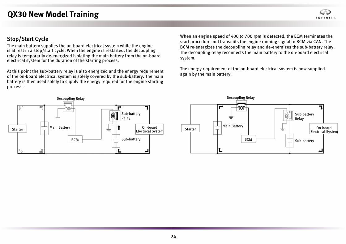
Batteries and AlternatorThe on-board electrical system battery is located at the left rear of the engine compartment when viewed in the direction of travel. An additional stop/start battery is installed in the front passenger footwell. The additional battery has a capacity of 12 Ah and prevents a voltage dip when the engine is started during the idle stop/start function.
Engine On-board Electrical System Battery
Alternator
1.6L & 2.0L Engines 70 Ah 150 A
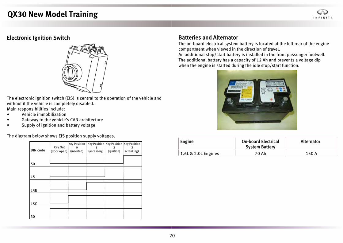
Electronic Ignition Switch
The electronic ignition switch (EIS) is central to the operation of the vehicle and without it the vehicle is completely disabled.Main responsibilities include:• Vehicle immobilization• Gateway to the vehicle’s CAN architecture• Supply of ignition and battery voltage
The diagram below shows EIS position supply voltages.
DIN code
50
15
15R
15C
30
Key Out (door open)
Key Position 0
(inserted)
Key Position 1
(accessory)
Key Position 2
(ignition)
Key Position 3
(cranking)
QX30 New Model Training

21
Energy Management SystemThe energy management system manages the provision (supply) and consumption (usage) of electrical energy to ensure mobility and a stable electrical consumer supply.Functions are as follows:• Engine ON energy management• Engine OFF energy management• Start/stop energy management
Battery Sensor
Latching Terminal Relay 30g
Sub Battery Relay
Decoupling Relay
Combination Meter
Electronic Ignition Switch Control Unit
ECM Alternator
BCMCommunication
Line
CAN Communication Line
CAN Communication Line
Communication Line
QX30 New Model Training

22
Engine ON Energy ManagementThe engine ON energy management function ensures the stability of the on-board electrical system as well as an even charge balance in the battery. Because the power output of the alternator is dependent on engine speed and temperature, plus the fact that many consumers are in use simultaneously, overload situations can arise that need to be buffered by the battery.
When such an overload situation lasts for an extended period or when the charging capacity of the battery is low, a negative charge/discharge ratio may result that could impair the engine’s starting capability.
In situations where the on-board electrical system is overloaded for prolonged periods, engine ON energy management works to increase the power output of the alternator and also reduces the consumers in order to balance the charge/discharge ratio of the battery.
Engine OFF Energy Management The engine OFF energy management function safeguards the stability of the on-board electrical system when the vehicle is at idle stop. The functionality is integrated in the BCM and serves to preserve the available voltage/amperage of the main battery.
The vehicle is deemed to be electrically dormant 75 minutes after ignition OFF. At 90 minutes, the BCM requests a battery voltage/current/temperature reading from the battery sensor and continues to do so every 15 minutes thereafter.
If a current draw significantly over 50 milliamps is detected, any remaining consumers may be switched off by the BCM activating the (battery switched) 30g relay.
The 30g relay is switched off six hours after ignition OFF. Door handle capacitors stay charged for a minimum of 72 hours.
Battery Sensor
Latching Terminal relay 30g
Electronic Ignition Switch Control Unit
CAN Communication
Line
Communication Line
BCM
Latching Terminal Relay 30g
QX30 New Model Training

23
Pyrofuse Battery Sensor
Sub-battery Relay
Additional Stop/Start Battery
Decoupling Relay
QX30 New Model Training
Stop/Start Energy Management
The ECM continuously assesses the stop/start system conditions. When the requirements are fulfilled, the idle stop/start function is enabled. When the vehicle comes to rest, the ECM evaluates all relevant data, transmits a stop enable signal, and stops the engine. The ECM also communicates an engine OFFsignal to the BCM via CAN to prevent the initiation of the energy OFF management function. The driver is notified the function is active at engine shutoff by the stop/start symbol in the combination meter.
24
When an engine speed of 400 to 700 rpm is detected, the ECM terminates the start procedure and transmits the engine running signal to BCM via CAN. The BCM re-energizes the decoupling relay and de-energizes the sub-battery relay. The decoupling relay reconnects the main battery to the on-board electrical system.
The energy requirement of the on-board electrical system is now supplied again by the main battery.
Decoupling Relay
Starter
BCM
On-board
Sub-battery Relay
Electrical System
Sub-battery
Main Battery
Sub-battery Relay
On-board Electrical System
Sub-battery
Decoupling Relay
Main Battery
BCM
Starter
QX30 New Model Training
Stop/Start CycleThe main battery supplies the on-board electrical system while the engineis at rest in a stop/start cycle. When the engine is restarted, the decouplingrelay is temporarily de-energized isolating the main battery from the on-boardelectrical system for the duration of the starting process.
At this point the sub-battery relay is also energized and the energy requirement
of the on-board electrical system is solely covered by the sub-battery. The main
battery is then used solely to supply the energy required for the engine starting
process.

25
Network ArchitectureNetwork OverviewThe ever-increasing demands on the on-board electronic systems in the fields of vehicle safety, comfort, communications, and diagnosis require wider and wider networking of vehicle systems to allow the necessary information to be exchanged.On QX30, many different networks are in use, making this the most complex Infiniti vehicle to date. The use of various network speeds combined with different manufacturer CAN and LIN types has necessitated the use of an increased number of gateway control units. This ensures an unrestricted flow of information.The following data bus systems and speeds are used on QX30:
TopologyThe diagram and module list on the following page show engineering development information for QX30. The terminology and structure will differ slightly from the final information found on the vehicle and in the service manual, but will give an overview of the structure and complexity of QX30 network architecture. NOTE: THIS DEPICTION COVERS ALL POSSIBLE NETWORKS USED FOR QX30 GLOBALLY.
System Transfer rate
Body CAN 1 125 kb/s
Body CAN 2 125 kb/s
Multimedia CAN 125 kb/s
Diagnostic CAN 500 kb/s
Powertrain CAN 500 kb/sFront End CAN 500 kb/s
LIN 22 KB/s
QX30 New Model Training
Chassis CAN 500 kb/s

26
QX30 New Model Training
Note: Graphic displays all possible BUS configurations available. Some systems may not be available for your market area.

27
Abbreviation Meaning
ALA Adaptive Light Actuator
AM Antenna Module
ANC/ASC Sound Control Module
APSS Active Pedestrian Safety System
AQS Air Quality Sensor
ASBM U Upper Accessory Switchbank Module
AVM Around View Monitor
AWD All-wheel Drive
BCM Body Control Module
BR Blower Regulator
CEPC Central Powertrain Regulator
CLA Curve Light Actuator
CPC Common Powertrain Controller
DCT Dual Clutch Transmission
DMFL Door Module Front Left
DMFR Door Module Front Right
DSI Direct Select Interface
DSM MS Door Switch Module/Memory Seat
DSM WM Door Switch Module Windows/Mirror
EC EC Mirror
ECM Engine Control Module
EIS Electronic Ignition Switch
EPKB Electronic Parking Brake
Abbreviation Meaning
EPS Electric Power Steering
ESL (ELV) Electric Steering Lock
ESP Electronic Stability Control
FCW Forward Collision Warning
FSCM Fuel System Control Module
FSM Flap Stepper Motors
GDO Universal Garage Motor
GEN Generator 150A
GPA Glow Plug Activator
HLI_FL Headlamp Interface Unit Left
HLI_FR Headlamp Interface Unit Right
HVAC Heating, Ventilation, and Air Conditioning
IBS Intelligent Battery Sensor
IBSM_R1 Blind Spot Monitoring Meter
IBSM_R4 Blind Spot Monitoring Slave
IC Instrument Cluster
IT_M Display Control Unit (IT Master Gen5)
K-GO Keyless-go
LCU_FL/FR LED Control Unit Front
LRR Long Range Radar
LSM/LRSM Light/Rain Sensor Module
MPC Multipurpose Camera
NAVI Navigation
Abbreviation Meaning
NOX_LT NOX Sensor Left
NOX_RT NOX Sensor Right
OCM Occupant Classification Module
OHCM Overhead Control Module
ORC Occupant Restraint Controller
PSMD Power Seat Module Driver
PSMP Power Seat Module Passenger
PTC-D PTC (Diesel Engine only)
PTS/APD Sonar System/Park Assist Control
RVC Rear Camera
SCCM Steering Column Control Module
SEAT D Seat Control Module Driver
SEAT P Seat Control Module Passenger
SIREN Intrusion Siren
SSP Stop/Start pump
STS Surface Temperature Sensor
SWSP Steering Wheel Switch Pad
TCU Telematic Control Unit
TGW Telematics Gateway
TM Trailer Module
TPMS Tire Pressure Monitoring System
TSSR Tilt Slide Sunroof Control Module
VLA Vertical Levelling Actuator
VTA SM Vehicle Theft Alarm Sensor Module
QX30 New Model Training
28
* Front End CAN* Powertrain CAN* Chassis CAN* Body CAN* Multimedia CAN
GatewaysThe following control units are classed as gateways:• Electronic Ignition Switch (EIS)• CAN gateway
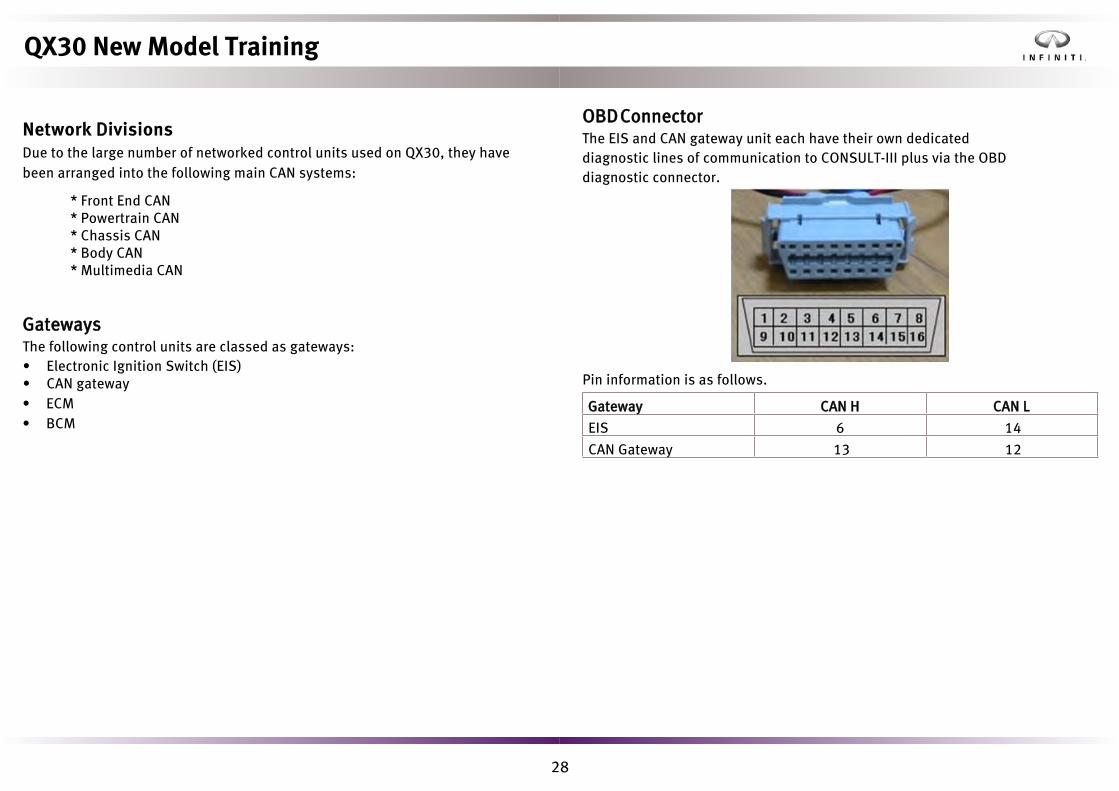
OBD ConnectorThe EIS and CAN gateway unit each have their own dedicated diagnostic lines of communication to CONSULT-III plus via the OBD diagnostic connector.
Pin information is as follows.
Gateway CAN H CAN L
EIS 6 14
CAN Gateway 13 12
Network DivisionsDue to the large number of networked control units used on QX30, they have been arranged into the following main CAN systems:
QX30 New Model Training
• ECM• BCM

29
1. Body CAN2. Diagnostic CAN3. Powertrain CAN4. Chassis CAN
4
1
2
3
Each potential distributor has a slot for every control unit’s CAN-H and CAN-L terminals. Two 30 ohm resistors are fitted in series to act as the signal buffer and replaces the more conventional use of 2 x 120 ohm resistors fitted in parallel (Multi-media (M-CAN) still uses 2 x 120 ohm resistors at termination points located in the CAN gateway).
CAN Potential Distributor Electrical Connector Number of Slots (Connector)
Powertrain 6
Diagnostic 6Body 13
Chassis 13
Resistance Value (normal condition at IGN-off) is as follows.
Terminal Resistance (Ohm)
CAN-H CAN-L 50-65
CAN Potential Distributor Electrical Connector (Body)
QX30 New Model Training
Potential Distribution Electrical Connector (PDEC)Most CAN networks have a CAN potential distributor electrical connector that acts as a centralized signal node point.The diagram below is the layout of node points for a LHD vehicle.

30
Reference voltage values for CAN potential distributors are shown below. (IGN-ON condition, refer to appropriate service manual for details)
Terminals Voltage
+ -
CAN Potential Distributor Electrical Connector
Terminal Terminal
CAN-H Ground 2.5-2.7(2.6-2.9)
CAN-L Ground 2.1-2.3(2.1-2.4)
CAN-H CAN-L 0.2-0.4(0.3-0.6)
QX30 New Model Training

31
• Direct injection with turbocharger• Valve lifter-less camshaft drive• Cylinder head cover with camshaft bearing cap• Intake and exhaust VTC• Crankshaft balancer (2.0L)Engine Management
• Engine control module• Fuel pump control module (FPCM)• Stop/start compatibility• Air/fuel ratio & knock sensor regulated fuel mappingElectrical System
• Part of the powertrain CAN• Revised connector designFuel System (Bosch)
• Single or tandem saddle fuel tank (FWD/AWD)• Internal fuel tank low-pressure fuel pump• Camshaft driven high-pressure fuel pump• Piezo operated injectors
Intake, Exhaust, and Emission Systems
• Throttle valve actuator• Mechanically controlled turbochargerOil and Cooling Systems
• Engine right side water pump• Engine left side engine oil cooler• Piston oil jet cooling• Chain drive engine oil pump
QX30 New Model Training
1.6L and 2.0L Turbo EnginesOverviewQX30 developed for the North American market is equipped with a 2.0 liter and 1.6 liter transverse version of the 2.0 liter 4-cylinder longitudinal turbo direct injection engine first seen on Q50 in early 2016.The engine mechanical and engine management systems are covered in depth in separate Q50 training. This section limits content to changes specific to its transverse application and also changes that have been made since its introduction in Q50.
Main Construction

32
Specifications1.6L Turbo (MEX) 2.0L Turbo
Configuration In-line 4 In-line 4
Displacement 1595 cc 1991 cc
Fuel System 50 bar direct injection 50 bar direct injection
Injector Piezo Piezo
Turbocharger Vacuum controlled boost regulation
Vacuum controlled boost regulation
Emission Regulation OBDII OBDII
Maximum Power 154 hp (115 kW)/5300 rpm 208 hp (155 kW)/5500 rpm
Maximum Torque 185 lb-ft (250 Nm)@1250-4000 rpm
258 lb-ft (350 Nm@1200-4400 rpm
Compression Ratio 10.3 9.8
Bore x Stroke 83 mm x 73.7 mm 83 mm x 92 mm
Drive FWD FWD/AWD
Service PointBefore carrying out diagnosis on the fuel system, release the fuel pressure as follows:1. Remove fuel pump fuse.2. Start the engine.3. After engine stalls, crank it two or three times to release remaining fuel
pressure.4. Turn ignition switch OFF.
QX30 New Model Training
33
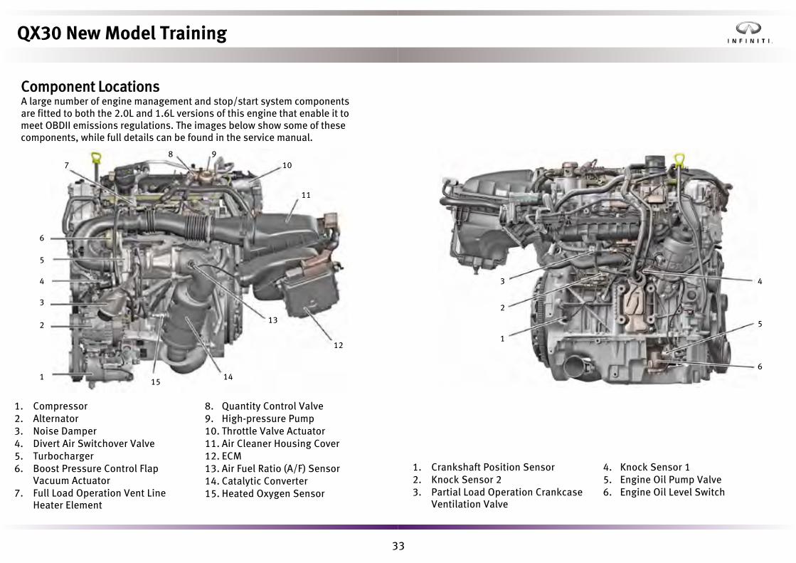
1. Compressor2. Alternator3. Noise Damper4. Divert Air Switchover Valve5. Turbocharger6. Boost Pressure Control Flap
Vacuum Actuator7. Full Load Operation Vent Line
Heater Element
8. Quantity Control Valve9. High-pressure Pump10. Throttle Valve Actuator11. Air Cleaner Housing Cover12. ECM13. Air Fuel Ratio (A/F) Sensor14. Catalytic Converter15. Heated Oxygen Sensor
1. Crankshaft Position Sensor2. Knock Sensor 23. Partial Load Operation Crankcase
Ventilation Valve
4. Knock Sensor 15. Engine Oil Pump Valve6. Engine Oil Level Switch
10
11
12
13
1415
7
6
5
4
3
2
1
8 9
3
2
1
4
5
6
QX30 New Model Training
Component LocationsA large number of engine management and stop/start system components are fitted to both the 2.0L and 1.6L versions of this engine that enable it to meet OBDII emissions regulations. The images below show some of these components, while full details can be found in the service manual.

34
79° Mark
79° Mark
Engine Timing Mark (Engine Side)
Engine Timing Mark (Crank Pulley Side)
Camshaft TimingThe cylinder head camshaft positions are reversed on the transverse version of this engine to improve turbo cooling. The method of camshaft timing however remains the same as the 2.0t engine used in the Q50.
Intake Exhaust
Longitudinal RHS LHS
Transverse LHS RHS
Intake Side
Exhaust Side
QX30 New Model Training
Crank PulleyBoth a cylinder 1 TDC timing mark and a 79° ATDC mark for high-pressure fuel pump removal are provided. Do strike or drop parts during removal and assembly.

35
QX30 New Model Training
Crankshaft PositionThe new increment wheel consists of a metal support on which a rubber track filled with ferrite particles is vulcanized in axial or radial form. The signal is required for recording the engine speed and rotational angle in both forward and reverse directions as the engine comes to rest. This enables quicker engine restarting.The wheel must never come within the vicinity of a magnetic field as this could damage the wheel causing engine performance issues. Cleanliness is also important.

36
• Engine running• Outside temperature between 14°F (-10°C) and 104°F (40°C)• Engine hood closed• Battery temperature between 32°F (0°C) and 140° (60°C)• Complete system diagnosis no malfunction detected• Vehicle driven above 5 mph (8 km/h) after engine key start• Vehicle driven above 10 mph (15 km/h) after engine restart*• Interior temperature within regulated rangeWhen the function requirements are fulfilled, the engine will shut off automatically when the vehicle is stopped. The driver is notified of the stop/start system operation by the stop/start indicator in the multifunction display of the combination meter.
The stop/start system consists of the following partial functions:• Function sequence for automatic engine stop• Function sequence for automatic engine restart• Function sequence for forced engine restart (a start dictated by the system)• Function for power supply to on-board electrical system
*QX30 will activate stop/start function up to four times before functionis inhibited if vehicle speed does not exceed 10 mph (15kph) such asduring stop-and-go traffic. Stop/start function will resume aftervehicle has been driven in excess of 10mph (15kph).
Stop/Start Indicator: The conditions for the stop/start system are fulfilled, engine is stopped
QX30 New Model Training
Qrmn-Qr_pr QwqrckRfc q_kc qrmn-qr_pr qwqrck gq _nnjgcb rm _jj OV1. kmbcjq, Rfc qrmn-qr_pr qwqrck pcosgpcq _jj md rfc dmjjmugle amlbgrgmlq `cdmpc dslargml ugjj maasp8
Stop/Start Cancel Switch: System is active when LED is illuminated

37
Twin Battery ManagementSub Battery Relay
• Controlled by BCM• Activated during a stop/start engine restart• Sub battery is switched through to the on-board electrical systemDecoupling Relay
• Controlled by BCM• Deactivated during a stop/start engine restart• Isolates the main battery from the sub battery• Ensures main battery is free to support engine starting• Reactivated once engine has startedAdditional 12V, 12 Ah Sub Battery
• Located under the passenger side of the instrument panel• Supplies energy to comfort and convenience features• Ensures no loss in performance during a stop/start engine restartCurrent and Temperature Sensor Modules
• Connected to BCM• Attached to main and sub battery negative terminals• Monitors battery voltage, current, and temperature
Crankshaft position sensor
Accelerator pedal position sensor
Engine coolant temperature sensor
Clutch pedal switch (M/T models)
Start enable clutch pedal switch (M/T models)
MT main shifter shaft position sensor (M/T models)
Air bag diagnosis sensor unit
TCM (A/T models)
Electronic stability program control unit
Steering column control module
A/C auto amp (auto A/C system)
A/C auto amp (manual A/C system)
Left front door control unit (LHD models)
Right front door control unit (RHD models)
Combination meter
ICC sensor
BCM
BCM
FPCM
Starter motor
Starter relay
Direct crash signal
Indirect crash signalStatus of driver seat belt
Gear range status signal
Each wheel speed signalBrake actuationEngine stop prohibitionEngine stop releaseEngine start request
Steering wheel angle signal
A/C statusEngine stop prohibitionEngine start request
Front door switch (driver side) signal
Vehicle speed signal
Stop/start indicator signal
Engine torque requirement signal
Engine stop prohibitionEngine start requestHood switch signalStop/start OFF switch signal
Stop/start switch signal
Upper control panel control unit
Fuel pump pressure request signal
Fuel pressure signal
QX30 New Model Training

38
Gear RatiosDCT is favored over continuously variable transmission (CVT) as it can handle higher torque applications on QX30 between 258 lb-ft to 331 lb-ft (350 Nm to 450 Nm).
1.6L 2.0L
2WD 2, AWD
1st Gear 3.8571 3.8571
2nd Gear 2.4286 2.4286
3rd Gear 2.9048 2.6667
4th Gear 1.1892 1.0488
5th Gear 0.8723 0.7755
6th Gear 1.1622 1.0488
7th Gear 0.9362 0.8367
Reverse Gear 3.0984 3.3750
Final Gear 3rd, 6th and 7th 2.654 2.654
1st, 2nd, 4th, 5th and Reverse
4.6 4.6
QX30 New Model Training
GE7F30A Dual Clutch TransmissionOverviewThe dual clutch transmission combines the sporty dynamics of a manual transmission with the convenience of an automatic transmission.
The GE7F30A is a three-shaft manual transmission with two multi-disc clutches contained in a single housing. An internal TCM and electro-hydraulic control valve manages the automatic clutch operation and gear changes. Steering wheel-mounted paddle shifters provide a manual gear selection option.
Heat generated by the constant activation of the multi-disc clutches is handled by an active oil cooling system.
The GE7F30A is suitable for use with the stop/start function. When the stop/start function is active (engine off), an electric auxiliary oil pump supplies the shift elements and actuators of the electro-hydraulic transmission control system with hydraulic pressure.

39
Main Components
1. Differential Pinion2. Oil Heat Exchanger3. Dual Clutch4. Hollow Shaft5. Internal Shaft6. Clutch Housing7. Oil Filter
8. Output Shaft 19. Output Shaft 210. Transmission Housing11. TCM Electrical Connector12. TCM13. Park Pawl System14. Oil Pan
27
11
9
10813
14
12
3
56
41
Gear Train Operation The gear train comprises: • An input shaft containing an internal solid shaft and an outer hollow shaft.
• The internal shaft has three fixed gears and a speed sensor rotor.• The hollow shaft has two fixed gears and a speed sensor rotor.
• Two output shafts containing the idler gears, synchronizers and one fixedgear each.
• A park pawl gear fitted to output shaft 1.• A differential pinion with spur gear.
Power flow takes place via the corresponding internal or hollow shaft fixed gear to the associated output shaft idler gears, depending on which clutch is engaged.
Note that all gears are splined together with the respective shafts without the synchronizer engaged are designated fixed gears.
Gears 1-7 and Reverse gear are idler gears that can be braked by synchronization devices and positively connected to the respective output shaft.
QX30 New Model Training

40
Gear Train Construction
1. Internal Shaft2. Hollow Shaft3. Output Shaft 14. Output Shaft 25. 7th Gear Idler6. 3rd Gear Idler7. Reverse Gear Idler8. 6th Gear Idler9. Output Shaft Fixed Gear 2
10. Internal Shaft Fixed 5th/7th Gear11. Internal Shaft Fixed 3rd Gear12. Internal Shaft 1st Fixed Gear13. Hollow Shaft Fixed 2nd/Reverse Gear14. Hollow Shaft Fixed 4th/6th Gear15. 5th Gear Idler16. 1st Gear Idler17. 2nd Gear Idler18. 4th Gear Idler
19. Output Shaft Fixed Gear 120. Spur Gear (Differential Pinion)21. Shift Fork22. Sliding Sleeve23. Shift Rod24. Park Pawl Gear25. Sensor Rotor26. Gear Actuator CylinderA. Tapered Roller Bearings
2
20
4
1
3
20
226
452123
26
15
324222123
26
10
23
521621721
8
9
A
A
10
25
A
24
1
A
26
1
A
2
A
1112
13
21
25
21
14
1522
16172218
19
20
QX30 New Model Training

41
With the ignition ON in Neutral, both clutches are open. The drive shafts are at a standstill and no force is transmitted into the transmission. However both Gear 1 and Reverse are pre-selected in anticipation of driver requirements. Torque transfer takes place as follows on an alternating basis between the outer multi-disc clutch (K1) and the inner multi-disc clutch (K2) of the dual clutch module.
As the engine, transmission, and road speeds/loads increase, so does the transmission oil clamping force required to stop the multi-disc clutch plates from slipping.The internal shaft and hollow shaft speed sensors ensure the appropriate transmission oil pressure is applied to clutches K1 and K2 in all operating conditions.
Clutch Open Clutch Closed
No torque transmission Torque transmission
Internal Shaft Outer Clutch (K1) Gears 1, 3, 5 & 7
Hollow Shaft Inner Clutch (K2) Gears 2, 4, 6 & Reverse
Dual Clutch Construction
1. Internal Shaft2. Hollow Shaft3. Drive Plate4. K1 Clutch External Plates5. K1 Clutch External Plate Carrier6. K1 Clutch Internal Plates7. K1 Clutch Internal Plate Carrier8. K2 Clutch External Plate Carrier9. K2 Clutch External Plates10. K2 Clutch Internal Plates
11. K2 Clutch Internal Plate Carrier12. Drive Gear (Oil Pump)13. Centrifugal Return Spring Package14. Clutch Hub with Oil Duct15. K1 Clutch Pressure Chamber16. K1 Clutch Piston17. K2 Clutch Piston18. Clutch Cover19. K2 Clutch Pressure Chamber
18
3
7
910
11
19
21
4
6817516
13
15
14
3
4
5 6 78
9
10
1112
131
2
QX30 New Model Training
Dual Clutch OperationThe dual clutch assembly contains two multi-disc clutches that are alternately electro-hydraulically actuated to engage or disengage. Clutch K1 is coupled to the internal shaft and clutch K2 is coupled to the hollow shaft. The gear expected to be engaged next is pre-selected by the TCM.

42
1. Internal Shaft 2. Hollow Shaft
1 2
K1
K2
Neutral
1st Gear
K1
Multiple Cone Synchronization
QX30 New Model Training
Power FlowEngine torque output is transferred to the DCT via the crankshaft drive plate.
Depending on clutch K1 or K2 engagement, the DCT internal shaft or hollow shaft transmits the torque to the driven road wheels via output shafts 1 and 2 to the pinion differential.The TCM controls gear selection via the hydraulically-operated internal shift mechanism, providing uninterrupted torque transfer shift operations.The power flow of the gears is shown in the following illustrations.
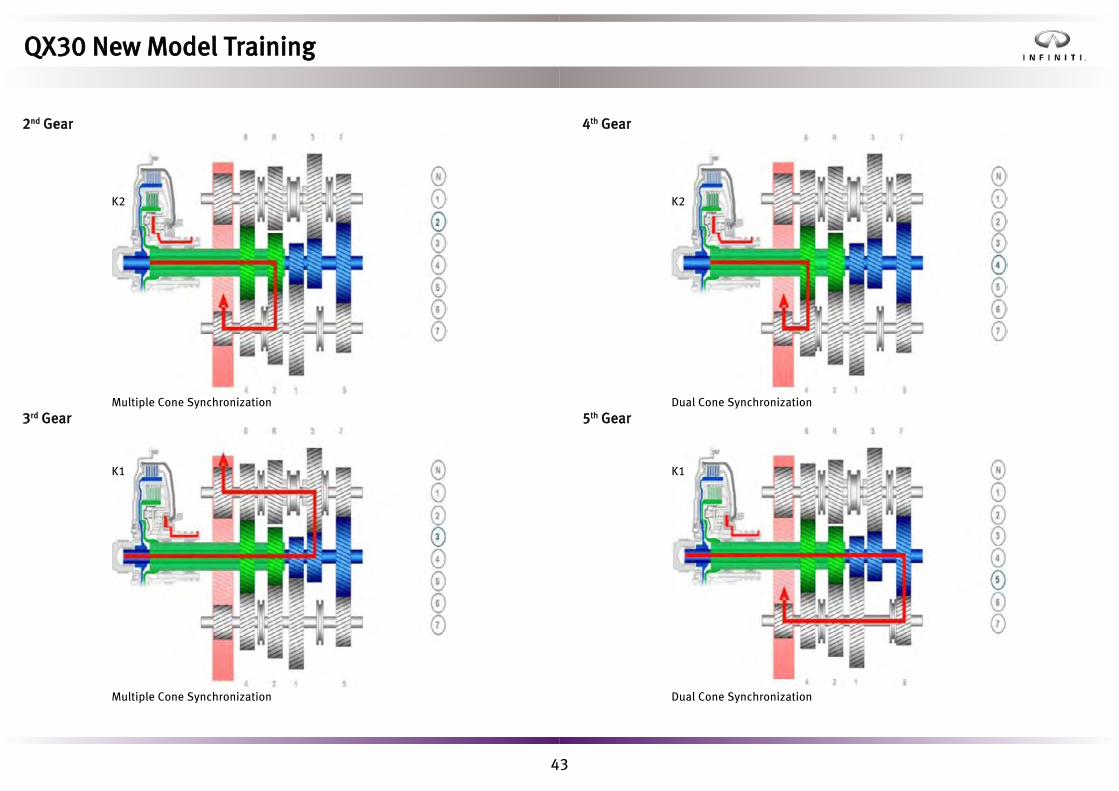
43
2nd Gear
K2
Multiple Cone Synchronization3rd Gear
K1
Multiple Cone Synchronization
4th Gear
K2
Dual Cone Synchronization5th Gear
K1
Dual Cone Synchronization
QX30 New Model Training

44
6th Gear
K2
Dual Cone Synchronization7th Gear
K1
Dual Cone Synchronization
Reverse Gear
K1
Single Cone Synchronization
Reverse Gear OperationReverse gear is not driven by a fixed gear on one of the drive shafts, but rather by the gear wheel for 2nd gear on the opposite output shaft. This results in the following power flow: The driving power is transmitted from the hollow shaft via the fixed gear to the gear wheel of 2nd gear. Gear wheel 2 transmits the power to the reverse gear, since it is always meshed with this. The reverse gear is permanently connected to the synchronizer body of the right gearshift sleeve so that it is frictionally connected to the adjacent gearwheel for 3rd gear. Gearwheel 3 transmits the power via the two fixed gears on drive shaft one to the gearwheel of first gear. Via the right gearshift sleeve, gearwheel 1 is frictionally connected to output shaft 1. The driving power is transmitted via the fixed gear of output shaft 1 to the differential, which now turns in the opposite direction as the other gears. The gear ratio here is similar to 1st gear.
QX30 New Model Training

45
• Shift and control solenoid valves• Electric auxiliary oil pump• Hydraulic park pawl actuation• Electric park pawl releaseThe integrated electric auxiliary oil pump works in conjunction with amechanical oil pump.
A. Electrical Connector1. Clutch Temperature Sensor2. Hollow Shaft RPM Sensor
3. Engine Speed Sensor4. Internal Shaft RPM Sensor
4
3
2
1
A
Shift SelectorLike an automatic transmission, park, neutral, drive and reverse can be engaged. Three modes are also available.• Manual shifting using the steering wheel paddles• Economy mode• Sport modeSelection information is displayed in the central area of the combinationmeter.
1. Vehicle Information Display2. Parking Brake Indicator Lamp3. Parking Brake Warning Lamp4. Engine Diagnosis Indicator Lamp
5. Transmission Mode Display6. Gear Indicator7. Instrument Cluster
2 3
17
65
4
QX30 New Model Training
Control Valve AssemblyThe control valve assembly includes an electro-hydraulic valve block, the TCM,and auxiliary oil pump.The valve body contains the components involved in gearshift, lubrication, and control processes, and the internal sensor system includes RPM, temperature, pressure and position sensors.The TCM evaluates internal and incoming signals/requests from other control units via CAN to perform the following:
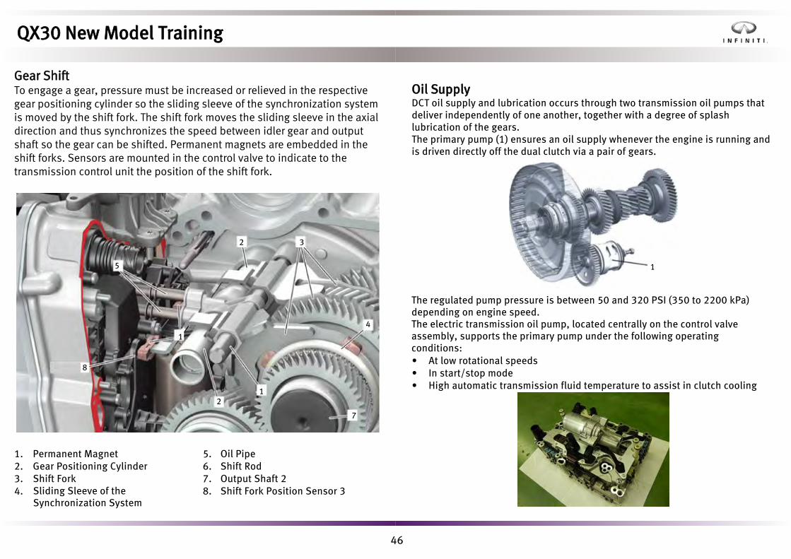
46
1. Permanent Magnet2. Gear Positioning Cylinder3. Shift Fork4. Sliding Sleeve of the
Synchronization System
5. Oil Pipe6. Shift Rod7. Output Shaft 28. Shift Fork Position Sensor 3
32
4
5
21
7
8
1
Oil SupplyDCT oil supply and lubrication occurs through two transmission oil pumps that deliver independently of one another, together with a degree of splash lubrication of the gears.The primary pump (1) ensures an oil supply whenever the engine is running and is driven directly off the dual clutch via a pair of gears.
The regulated pump pressure is between 50 and 320 PSI (350 to 2200 kPa) depending on engine speed.The electric transmission oil pump, located centrally on the control valve assembly, supports the primary pump under the following operating conditions:• At low rotational speeds• In start/stop mode• High automatic transmission fluid temperature to assist in clutch cooling
1
QX30 New Model Training
Gear ShiftTo engage a gear, pressure must be increased or relieved in the respective gear positioning cylinder so the sliding sleeve of the synchronization system is moved by the shift fork. The shift fork moves the sliding sleeve in the axial direction and thus synchronizes the speed between idler gear and output shaft so the gear can be shifted. Permanent magnets are embedded in the shift forks. Sensors are mounted in the control valve to indicate to the transmission control unit the position of the shift fork.

47
1. Cooler2. Expansion Reservoir3. DCT Oil Heat Exchanger4. Turbocharger5. Coolant Pump6. Engine7. Engine Oil Heat Exchanger8. Thermostat
9. Heating Matrix10. Air Conditioning Circulation11. DCT Cooling Circulation PumpA. DCT Cooling Circuit Return B. Coolant Return to the Engine C. Coolant FeedD. Coolant Circuit Expansion
Park PawlA parking pawl locking system is fitted to prevent the vehicle from rolling away when parked, and is selected via the shift selector (P) position.The electric transmission oil pump supplies the oil pressure to apply and release the park pawl. CONSULT can be used to disengage the park pawl if the electrical system is in working order.
NOTE: Should the electrical system fail, there is no emergency park pawl release mechanism beneath the shift selector.
2
67
9
1
10
5
811
3 ABCD
4
1. Emergency Push Rod2. Pressure Cone3. Park Pawl Locking Solenoid4. Permanent Magnet5. Park Pawl Position Sensor6. Piston7. Piston Spring
8. Pressure Cone Spring9. Park Pawl Gear10. Coil Spring11. Park DetentA. Pressure Chamber (Position P) B. Pressure Chamber (Position not P)
5
4
67
A
3
8
21
11 10
9B
QX30 New Model Training
Transmission CoolingDue to ever frequent shift and clutch operations which can involve hillstarts and high loads, the transmission oil requires temperature management to avoid malfunctions due to insufficient cooling. The DCT oil heat exchanger is located on the transmission housing and forms the interface between the engine coolant circuit and automatic transmission fluid circuit.The transmission oil temperature is recorded by the TCM from the clutch temperature sensor and transmitted to the engine control module (ECM) via drivetrain CAN.The flow of coolant is controlled by the DCT cooling circulation pump from the engine control unit as required. The automatic transmission fluid returns to the transmission housing via a return duct.

48
1. Pressure Oil Filter 2. Suction Oil Filter
Diagnosis and RepairThe DCT can be divided into three distinct areas, and most problems associated with DCT are attributable to electrical aspects of operation.• The clutch housing with dual clutch module (cannot be disassembled).• The mechanical gear train, differential, and park pawl• The electrical TCM and control valve assembly (can be diagnosed and
replaced as separate units).
Many parameters are available in Data Monitor, including:• Clutch application and slip (internal speed sensors)• Gear selection solenoid actuation• Internal oil pressure and electric pump activation• Cooling management
There is no requirement for adapting the multi-disc clutch touch points. This is done automatically.If the electrical pump fails, no gears can be selected. If clutches slip, suspect the mechanical oil pump.With the ignition ON and engine OFF, if you can shift from N to P the electric pump is working.The DCT cannot be separated from the engine without removing both from the vehicle.If a DCT is transferred to another vehicle, a new TCM is required due to its immobilizer status.A service part control valve assembly can be installed, adapted to vehicle, and road tested for diagnostic purposes prior to marrying to the vehicle. After 40 ignition cycles, the valve assembly will marry itself to the vehicle and cannot be used on other vehicles.
1
2
QX30 New Model Training
MaintenanceContamination is the greatest threat to DCT longevity. When carrying out service and maintenance work, cleanliness is extremely important.There are two oil filters - an external pressure oil filter and a suction oil filter located in the oil sump.Oil change interval is 60,000 mi/5 years and includes both pressure and suction oil filter replacement.Oil level check is only possible using CONSULT-III plus.Oil level dipstick J-51940 is also required.

49
An oil pump in the rear final drive generates oil pressure if there is a difference in revolution speeds between the front and rear axles.The AWD control unit regulates the oil pressure using a solenoid valve and thus the drive torque transferred to the rear axle, depending on the driving situation.
1. Dual Clutch Transmission2. Left Front Drive Shaft3. Right Front Drive Shaft4. Transfer5. Rear Axle Propeller Shaft
6. Multiple Disk Clutch7. Left Rear Drive Shaft8. Rear Final Drive9. Right Rear Drive Shaft10. All Wheel Drive Solenoid Valve
5
10
78
9
4
3
2
1
6
QX30 New Model Training
All Wheel DriveThe automatically-controlled all wheel drive (AWD) uses a transfer at the dual clutch transmission and a multiple disc clutch integrated in the rear final drive assembly.On dry road surfaces and with smooth driving style, torque is applied 100% to the front axle but can be distributed to both axles if required. Operation of the multiple disc clutch enables up to 50% of the drive torque to be directed to the rear axle if traction is lost on the front axle.The propeller shaft turns constantly while driving.Torque capacity is 550 lb-ft (750 Nm).
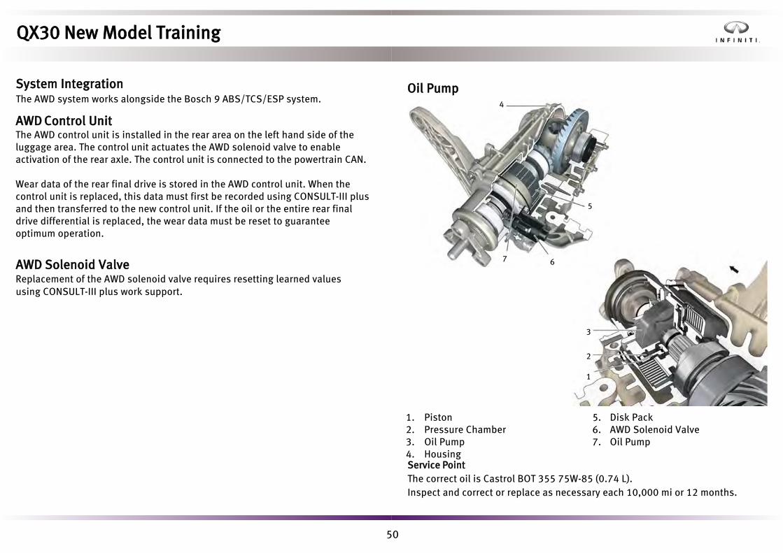
50
Oil Pump
5. Disk Pack6. AWD Solenoid Valve7. Oil Pump
1. Piston2. Pressure Chamber3. Oil Pump4. HousingService PointThe correct oil is Castrol BOT 355 75W-85 (0.74 L).Inspect and correct or replace as necessary each 10,000 mi or 12 months.
1
2
3
7 6
5
4
QX30 New Model Training
System IntegrationThe AWD system works alongside the Bosch 9 ABS/TCS/ESP system.
AWD Control UnitThe AWD control unit is installed in the rear area on the left hand side of theluggage area. The control unit actuates the AWD solenoid valve to enableactivation of the rear axle. The control unit is connected to the powertrain CAN.
Wear data of the rear final drive is stored in the AWD control unit. When the control unit is replaced, this data must first be recorded using CONSULT-III plus and then transferred to the new control unit. If the oil or the entire rear finaldrive differential is replaced, the wear data must be reset to guaranteeoptimum operation.
AWD Solenoid ValveReplacement of the AWD solenoid valve requires resetting learned values using CONSULT-III plus work support.

51
Front Rear (AWD)
Rear (FWD)
QX30 New Model Training
SuspensionQX30 is equipped with fully independent front and rear suspension systems that provide maximum levels of driving stability and ride comfort. Three ride heights are available, depending on model.QX30 Base and QX30 Premium are fitted with standard suspension, while QX30 Sport has stiffer dampers and stronger springs, lowering the vehicle by 15 mm in comparison with the other models. This results in smaller roll angles during dynamic driving.A third ride height is available on the QX30 AWD. The AWD model is 30 mmhigher than QX30 base and premium models.Drive shafts are mounted to the wheel hubs as shown.

52
Road wheel movement is controlled by a lower forged aluminum transverse link, the suspension strut, and the steering inner and outer socket. The rack and pinion steering is behind the wheel center when viewed in the direction of travel.
1. Transverse Link2. Stabilizer Bar3. Suspension Strut
4. Steering Inner Socket5. Steering Outer Socket6. Sway Bar
1
6
2
4
5
3
QX30 New Model Training
Front SuspensionThe MacPherson strut suspension units feature hollow piston rods and aluminium head bearings to reduce weight. Coil spring retention cups are perforated for dirt removal. The dampers are progressive and mechanically switch from soft to harder damping over the first 10 millimetres of travel. The front sway bar is mounted to the vehicle body using low friction vulcanized rubber bushings and is connected to each suspension strut by low friction linkages to improve the response characteristics of the suspension.

53
The wheel hub and rear lower link are made of aluminium to reduce the unsprung mass. In addition, large rubber bushings are used to optimize ride comfort.Coil spring noise insulation between the body and rear axle is achieved by means of two elastomer shims.
1. Rear Lower Link2. Rear Suspension Member3. Trailing Arm4. Front Upper Link
5. Front Lower Link6. Top Mount7. Stabilizing Rod
1 2
3
4
5
6
7
Sway Bar
The shock absorber is connected to the body by an aluminium top mount. This has a soft cardan bearing that reduces friction in the shock absorber and and improves response characteristics.The rear axle sway bar is attached to the rear axle carrier using low friction vulcanized rubber bushings and is connected to the rear axle with conventional stabilizing rods.
QX30 New Model Training
Rear SuspensionThe four-link rear axle has three transverse control links and one trailing arm to absorb the forces at each rear wheel. This allows the longitudinal and lateral dynamics of the vehicle to be tuned selectively and independently of each other.
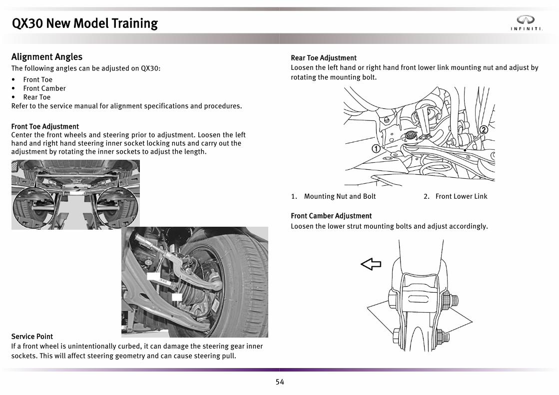
54
• Front Toe• Front Camber• Rear ToeRefer to the service manual for alignment specifications and procedures.
Front Toe AdjustmentCenter the front wheels and steering prior to adjustment. Loosen the left hand and right hand steering inner socket locking nuts and carry out the adjustment by rotating the inner sockets to adjust the length.
Service PointIf a front wheel is unintentionally curbed, it can damage the steering gear inner sockets. This will affect steering geometry and can cause steering pull.
1
2
Rear Toe AdjustmentLoosen the left hand or right hand front lower link mounting nut and adjust by rotating the mounting bolt.
1. Mounting Nut and Bolt 2. Front Lower Link
Front Camber AdjustmentLoosen the lower strut mounting bolts and adjust accordingly.
QX30 New Model Training
Alignment AnglesThe following angles can be adjusted on QX30:
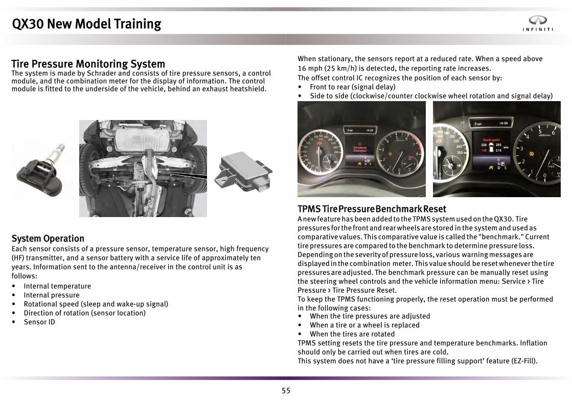
55
When stationary, the sensors report at a reduced rate. When a speed above 16 mph (25 km/h) is detected, the reporting rate increases. The offset control IC recognizes the position of each sensor by:• Front to rear (signal delay)• Side to side (clockwise/counter clockwise wheel rotation and signal delay)
System OperationEach sensor consists of a pressure sensor, temperature sensor, high frequency (HF) transmitter, and a sensor battery with a service life of approximately ten years. Information sent to the antenna/receiver in the control unit is as follows:• Internal temperature• Internal pressure• Rotational speed (sleep and wake-up signal)• Direction of rotation (sensor location)• Sensor ID
TPMS Tire Pressure Benchmark ResetA new feature has been added to the TPMS system used on the QX30. Tire pressures for the front and rear wheels are stored in the system and used as comparative values. This comparative value is called the "benchmark." Current tire pressures are compared to the benchmark to determine pressure loss. Depending on the severity of pressure loss, various warning messages are displayed in the combination meter. This value should be reset whenever the tire pressures are adjusted. The benchmark pressure can be manually reset using the steering wheel controls and the vehicle information menu: Service > Tire Pressure > Tire Pressure Reset.To keep the TPMS functioning properly, the reset operation must be performed in the following cases:• When the tire pressures are adjusted• When a tire or a wheel is replaced• When the tires are rotatedTPMS setting resets the tire pressure and temperature benchmarks. Inflation should only be carried out when tires are cold.This system does not have a ‘tire pressure filling support’ feature (EZ-Fill).
QX30 New Model Training
Tire Pressure Monitoring SystemThe system is made by Schrader and consists of tire pressure sensors, a control module, and the combination meter for the display of information. The control module is fitted to the underside of the vehicle, behind an exhaust heatshield.

56
• Sensor replacement• Control unit replacement• Tire or road wheel replacement• Performing a tire rotationID registration is not required if there is no change in TPMS pressure sensor.
TPMS Manufacturer Software Code Affected Models
Schrader SEL-WAL All QX30 models
Continental CONTI-CMF All other Infiniti models
Auto-learnShould the tool be unavailable, the system initiates an auto-learn procedure every time the vehicle is parked for 19 minutes or more. The auto-learn process is completed once the vehicle is driven above 16 mph (25 km/h), at which point any warning indicators will be extinguished. Within ten minutes of achieving a road speed of 25 mph (40 km/h) or more, the individual tire pressures and temperatures are available for display.
Service PointsThere are two sensor part numbers, depending on whether steel or alloy wheels are fitted. Steel wheel sensors have longer valve stems and protrude if fitted to alloy wheels.To prevent sensor damage when replacing a tire, undo the sensor securing nut and allow the sensor to drop into the old tire before removing from the wheel. Always use a new seal and securing nut when refitting the sensor.Inflating the new tire to the correct pressure will erase any stored DTCs and messages.NOTE: Unlike other Infiniti vehicles, the QX30 benchmark pressure is not set by the factory. It is important at pre-delivery inspection (PDI) to check and adjust the tire pressures prior to manually resetting the benchmark pressure via the steering wheel vehicle information menu.
QX30 New Model Training
Sensor ID RegistrationThe Infiniti tire pressure sensor activation tool and CONSULT or the Signal Tech IIcan be used to activate or register new sensors.
Sensor ID registration should be performed under the following circumstances:

57
TiresTire options and specification are shown in the table below.
Tire size Pattern Type Supplier
Summer Continental235/50R18 97V235/50R18 97H All Season Run Flat Continental
235/45R19 95V Summer Goodyear
Tires marked ‘MO’ or 'MOE'are specifically designed to complement the suspension and handling characteristics of QX30.Driving distance on a deflated run flat tire should be limited to approximately 50 miles (partially laden) and approximately 18 miles (fully laden) and reduced further according to average road speed, road conditions, and outside temperature. The vehicle speed must not exceed 50 mph.
Puncture RepairNo full size or emergency spare is available on QX30. Always refer to the owner’s manual information on maximum recommended speed and distance following a puncture warning with MOE or Run Flat tires.
Snow ChainsSnow chains are not recommended for use on the alloy wheels and tires for QX30.
QX30 New Model Training

58
WheelsThe following wheel sizes, specification, and style are available.
Service PointWhile other Infiniti vehicles feature wheel hub studs and tapered wheel nuts, the QX30 uses 5 wheel bolts with conical seats to secure each wheel to its wheel hub. Wheel bolt tightening torque for all Infiniti QX30 vehicles is 82 - 103 ft-lb (117 - 140 Nm). This is a higher value than other Infiniti models.The conical wheel bolt seat angle is different from other Infiniti models. Do not install wheels from other Infiniti models and always check the application when installing aftermarket wheels.
Accent Wheels18- and 19-inch accent wheels incorporate a laser cutting procedure in the paint application. The chosen accent color forms the primer coat to which the base coat is applied. The wheels are then machined to reveal the alloy surface in the normal manner. A final precision laser etching process reveals the accent color where required to a minimum line width of 0.3 mm. The whole wheel is then lacquered to compete the process.
Base Coat (Dark Grey Metallic)
Accent Color (Red/Purple)
Machined Surface
18-inch Wheel 19-inch Wheel
Standard Wheel (Machined Surface) Accent Color
17 in
ch w
heel
18 in
ch w
heel
19 in
ch w
heel
QX30 Sport
QX30 Premium
QX30
Styling packs
Without accent Purple Red
QX30 New Model Training

59
Front Disc Front CaliperSmall
(1.6L Engines)295 x 28t, Vented 60 mm Piston, Floating
Large
(2.0L Engines)320 x 30t, Vented 60 mm Piston, Floating
Sport 320 x 30t, Vented, Drilled 60 mm Piston, Floating
Rear Disc Rear Caliper
Small 295 x 1.0, Solid 34 mm Piston, Floating and Electric Parking Brake
Large 320 x 2.2, Vented 38 mm Piston, Floating and Electric Parking Brake
Pedal Force
Dec
eler
atio
n
ClassQX30 A-
Caliper identification is as follows:
Small Large Sport
QX30 New Model Training
Brake SystemThe QX30 hydraulic brake system is diagonally split utilizing a master cylinder with a 10" (25.4 cm) servo booster with a braking assistance ratio of 7.5:1. The system incorporates a feature known as 'Rise-up Brakes'. When pressed lightly, the pedal feel and brake performance match the pressure on the pedal. When pushed harder and faster however, the braking force increases exponentially to maximize braking performance. The disc and caliper specifications and options are shown below.

60
Bosch 9 ESP-CPI3 (with Intelligent Cruise Control ICC)
• 1 x Master cylinder pressure sensor (driver application)• 1 x Hydraulic module RH front wheel pressure sensor (system feedback)• 1 x Hydraulic module LH front wheel pressure sensor (system feedback)• ICC logic contained in long range radar control unit (LRR)
The steering wheel angle sensor is integrated into the steering column module. This module also contains the horn contact, air bag clock spring, and combination switch unit, and can only be replaced as a complete unit.The control unit, hydraulic valve block, ABS pump, and yaw sensor are also contained in a single unit. Two versions are available, depending on cruise control fitment and application type.
Yaw Rate/ Lateral G/ Longitudinal G Sensor (built in to ABS actuator)
Rear Wheel Speed SensorsFront Wheel
Speed Sensors
Vacuum Sensor
Steering Angle Sensor
ABS/ TCS/ VDC (ESC) Actuator & Controller
QX30 New Model Training
Brake Control SystemQX30 is equipped with a Bosch 9 ABS/TCS/ESP system.

61
Bosch 9 ESP-CPI1 (with Normal Cruise Control)
• 1 x Master cylinder pressure sensor (driver application)• Cruise control logic contained in Bosch 9ESP control unit
System OverviewThe Bosch 9 system is capable of the following functions.
• ABS - Anti lock braking system controls the brakes so the wheels do not lockduring hard braking or when braking on slippery surfaces.
• EBD – Electronic brake force distribution limits the rear brake pressure underheavy braking to prevent rear wheel lock up.
• ESP – Electronic stability program uses the vehicle brakes and engineoutput to control vehicle stability and direction. (Also known as VDC).
• ETS – Electronic traction control, otherwise known as TCS, limits wheel spinunder acceleration and remains active when ESP is switched off.
• 4ETS – Same as above for AWD vehicles.
• HSA – Hill start assist holds the hydraulic brakes on momentarily whenpulling away on a gradient.
• FEB – Forward emergency braking utilizes a front facing radar to monitorforward car movements and apply braking in an emergency situation.
These functions require no further explanation as they are present on other Infiniti models. A few extra notes are provided on HSA and FEB however.
Hill Start AssistHSA prevents the vehicle from rolling backwards while driving off up-hill on an inclined surface. Main requirements for activation are:• Vehicle stationary• Brake pressure created by the driverThe brake pressure is held for a maximum of one second before it is released. This allows the driver time to transfer from the brake pedal to accelerator to pull away smoothly without fear of vehicle roll-back.
QX30 New Model Training

62
Non-ICC Radar
Autonomous braking function is available in the following speed ranges:• 4-65 mph (7-105 km/h) for moving objects• 4-30 mph (7 -50 km/h) for stationary objects
The radar sensor requires no adjustment or calibration if removed or replaced.
ICC Radar
Autonomous braking function available in the following speed ranges:• 4-125 mph (7-200 km/h) for moving objects• 4-30 mph (7 -50 km/h) for stationary objectsThe radar sensor requires adjustment or calibration if removed orreplaced. FEB can be switched off by the driver using the vehicle displaysub menu.
A number of technologies work together in emergency braking situations:• Forward collision warning function (FCW) - Visually and audibally warns the
driver of a shortening distance.• Forward emergency braking function (FEB) – Full autonomous braking
initiated in critical situations if driver fails to brake. (Brake lights flash).• Brake assist function (BA) – If the driver does brake, the system applies
additional braking force up to the ABS threshold.
1. Steering Wheel-mounted Controls2. Distance Warning Light
3. Forward Emergency BrakingDisplay
Deceleration Full Braking
Distance
Vehicle Information Display
Instrument Panel
Radar
1 2 3
QX30 New Model Training
Forward Emergency BrakingThe forward emergency braking (FEB) autonomous braking function isstandard equipment on all QX30s and requires either the low specification(non ICC) or higher specification (ICC) front radar to help reduce the risk of collision with the vehicle in front. FEB is also referred to as forward collision avoidance (FCA) in some literature.

63
Main Function Sub Function Sub Function Title Function Description
ABSAnti-lock Braking System
BSC Brake Slip Control Controls the slip demand of the front outside wheel when cornering (oversteer interventions only). All other wheels are torque controlled.
DTC Drag Torque Control Sudden throttle closures or downshifting on low friction road surfaces when braking, can cause driven wheels to exert too high an engine drag torque. This leads to an unstable understeer or oversteer situation. DTC reduces the engine braking slip on the driven wheels by slightly increasing the engine torque, helping to maintain vehicle stability and steerablity.
TCSTraction Control System
PTC Powertrain Torque Control PTC is the area of TCS that modifies engine torque if too much wheel slip is detected when the driver is accelerating the vehicle.
BTC Brake Torque Control BTC is the area of TCS that uses the ABS hydraulic valve block and pump to alter the torque applied to individual driven wheels when wheel slip occurs.
BTM Brake Temperature Model Calculated brake temperature based on system brake pressure and time. Some Bosch 9 sub system functionality is downgraded or temporarily switched off if the temperature threshold is exceeded.
ESPElectronic Stability Program
VDC Vehicle Dynamics Control VDC is the area of ESP involved in the vehicle's yaw management by comparing the measured yaw rate with the driver’s wishes.Stability control of excess understeer/oversteer or wheel slip situations is governed through brake pressure modulation which can alter the forces acting on individual wheels, and if performed asymmetrically, can induce a yaw moment about a vehicle's vertical axis.
TSM Trailer Sway Mitigation ESP intervenes with the use of the ABS hydraulic valve block and pump when unexpected trailer sway is measured around the vehicles vertical axis.
CBC Corner Brake Control When braking in a curve, forces on the rear axle are reduced, leading to less rear wheel grip and a possibility of oversteer. At the same time, a reduction in forces on the curve inside wheels can lead to increased brake slip and an early activation of ABS control.To counteract this yaw moment, the difference in brake forces between the curves inside and outside wheels is increased.
ROM Roll-over Mitigation ROM attempts to avoid a vehicle roll-over situation by actively braking single wheels to limit the lateral acceleration.
QX30 New Model Training
Other FunctionalityIncluded within the operation of the main functions of the Bosch 9 system are a number of supporting sub functions.
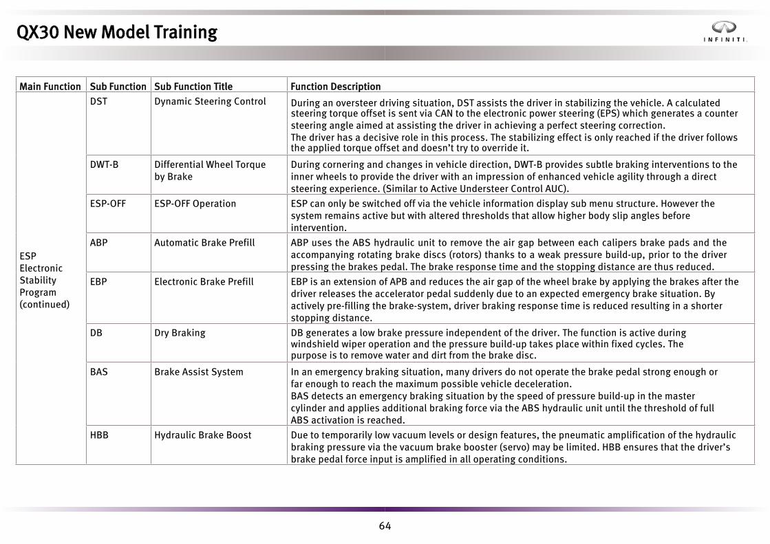
64
Main Function Sub Function Sub Function Title Function Description
ESPElectronic Stability Program (continued)
DST Dynamic Steering Control During an oversteer driving situation, DST assists the driver in stabilizing the vehicle. A calculated steering torque offset is sent via CAN to the electronic power steering (EPS) which generates a counter steering angle aimed at assisting the driver in achieving a perfect steering correction. The driver has a decisive role in this process. The stabilizing effect is only reached if the driver follows the applied torque offset and doesn’t try to override it.
DWT-B Differential Wheel Torque by Brake
During cornering and changes in vehicle direction, DWT-B provides subtle braking interventions to the inner wheels to provide the driver with an impression of enhanced vehicle agility through a direct steering experience. (Similar to Active Understeer Control AUC).
ESP-OFF ESP-OFF Operation ESP can only be switched off via the vehicle information display sub menu structure. However the system remains active but with altered thresholds that allow higher body slip angles before intervention.
ABP Automatic Brake Prefill ABP uses the ABS hydraulic unit to remove the air gap between each calipers brake pads and the accompanying rotating brake discs (rotors) thanks to a weak pressure build-up, prior to the driver pressing the brakes pedal. The brake response time and the stopping distance are thus reduced.
EBP Electronic Brake Prefill EBP is an extension of APB and reduces the air gap of the wheel brake by applying the brakes after the driver releases the accelerator pedal suddenly due to an expected emergency brake situation. By actively pre-filling the brake-system, driver braking response time is reduced resulting in a shorter stopping distance.
DB Dry Braking DB generates a low brake pressure independent of the driver. The function is active during windshield wiper operation and the pressure build-up takes place within fixed cycles. The purpose is to remove water and dirt from the brake disc.
BAS Brake Assist System In an emergency braking situation, many drivers do not operate the brake pedal strong enough or far enough to reach the maximum possible vehicle deceleration. BAS detects an emergency braking situation by the speed of pressure build-up in the master cylinder and applies additional braking force via the ABS hydraulic unit until the threshold of full ABS activation is reached.
HBB Hydraulic Brake Boost Due to temporarily low vacuum levels or design features, the pneumatic amplification of the hydraulic braking pressure via the vacuum brake booster (servo) may be limited. HBB ensures that the driver’s brake pedal force input is amplified in all operating conditions.
QX30 New Model Training

65
Main Function Sub Function Sub Function Title Function Description
ESPElectronic Stability Program (continued)
HBC Hydraulic Boost Failure Compensation
HBC supplements or replaces the actuation of brake pedal force amplification if the brake vacuum booster (servo) fails.
CDP Controlled Deceleration of Parking Brake
In an emergency situation, the electronic parking brake can be activated to assist in bringing the vehicle to rest.
ABL Adaptive Brake Light To warn following traffic that the driver is carrying out emergency braking, the stop lamp is actuated in flashing mode in such situations and the hazard warning flasher system is automatically switched on when stationary.
CCA Dynamometer Function CCA allows rolling road vehicle brake testing and chassis dynamometer work to be performed without intervention of ABS/TCS/ESP.
QX30 New Model Training

66
Parking Brake ActuatorThe following images show the internal workings of the parking brake actuator assembly.
1. Caliper2. Pads3. Disc (Rotor)4. Bracket5. Piston
6. Spindle Assembly7. Seal8. Dust Seal9. Motor
1. Motor2. Electrical Connector
3. Drive Belt4. Epicyclic Gear Train
21 7 9
4
38
5 6
1
2
3 4
QX30 New Model Training
Electric Parking BrakeThe electric parking brake (EPB) system includes two electric parking brake actuators fitted to the rear brake calipers, a parking brake switch located under the rotary lighting switch, and a parking brake control unit fitted in the rear luggage compartment.

67
• Pushing the parking brake switch applies the parking brake up to a vehiclespeed of 2 mph (3 km/h).
• Pulling the parking brake switch releases the parking brake.• Automatic Release function on accelerator pedal application.
To prevent vehicle movement as the hot brakes cool, the system can reapply the parking brake within 30 minutes of the vehicle being parked. The parking brake is released automatically when in D or R. However, to prevent rolling down hill, if the driver’s door is opened when in D or R, the parking brake is automatically applied and the transmission P range is selected.
Emergency ModeAt speeds above 2.5 mph (4 km/h), if the parking brake switch is pressed and held:
• The ABS reduces excess speed by ABS pump activation to build brakingpressure at the calipers.
• At and below 2.5 mph (4 km/h), the parking brake is applied.• If the switch is released at any point, the parking brake is released.
Fail SafeIf the system fails with the parking brake applied, the piston spindle assemblies must be wound back manually using a 7 mm hex wrench.
Service PointsWhen performing brake pad replacement, a service position can be activated to fully retract the brake caliper pistons. This also prevents the system from inadvertently reapplying the parking brake while working on the system. The service position can be activated with or without CONSULT-III plus. To manually set the service position, perform the following:• Set ignition to the accessory position• Make sure the combination meter displays the mileage screen• Press and hold the steering wheel phone switch and then press the OK
button for five seconds.• Brake service options are displayed• Select the correct option and press OK• Press OK to return to normal operation
QX30 New Model Training
System OperationThe EPB control unit monitors the rise in electrical current as the rear brake pads clamp the rear rotor discs. Clamping is stopped when the electrical current reaches a set threshold.

68
1. Rack and Pinion Steering Gear2. Torque Sensor
3. Actuator Motor4. Control Unit
Compared to a conventional hydraulic power steering system, QX30’s electric power steering has the following advantages:• Improved steering feel and flexibility of control• Better fuel economy (no steering pump)• No fluid and associated pipework required (eliminates leaks)• Compact design• Speed dependent steering force assistance• Steering return control• Side-pull compensation• Communication and diagnosis through CONSULT-III plusThe steering column is a collapsible type and also features telescopic and tilt convenience.The steering gear comes as a self-contained unit comprising a rack and pinion assembly, torque sensor, actuator motor, and control unit.The steering angle sensor is part of the steering column control unit. Speed sensitive steering force assistance is provided by the actuator motor acting directly on the rack and pinion steering gear, depending on the driver input feedback from the torque sensor.Counter-steering stabilization logic is incorporated in the steering ECU, and complements braking and engine intervention elements of ESP.
Service PointCurbing the front wheels can damage the steering gear inner sockets. This affects steering geometry and can cause steering pull.Inner sockets can be changed as shown.
2
3
1
4
1. Inner Socket 2. Outer Socket
1
2
1
2
QX30 New Model Training
SteeringQX30 is equipped with a fully electric, speed sensitive steering system. It enables the Intelligent Parking Assist feature and has integration with many other systems including stop/start.

69
Two steering wheels styles are offered, depending on model. Workshop ModeSteering assistance is also available if the vehicle is moved with the ignition on.
EPS Control Unit ReplacementThe following must be performed with CONSULT-III plus:• Steering center position resetting• Reset of coding• EPS torque sensor calibration• Relearning
Service PointsWhen performing diagnosis, note that any past DTCs stored in the memory may have an effect on system functionality.
Regarding possible vehicle pull issues, after normal checks have been confirmed (tire pressures, brakes not binding, etc.), drive the vehicle for approximately 18 miles (30 km) at speeds around 35 mph (60 km/h). After this, the vehicle has made enough readings to learn the steering angle offset.
Be aware that QX30 base and premium, and QX30 AWD steering rack assemblies look identical and are physically interchangeable. The ECU contains all steering maps and auto configures to the vehicle it is installed into, regardless if the wrong steering rack is installed. However, if this occurs, VDC issues are likely as the ECU will assume either an oversteer or understeer condition, depending the vehicle and rack installed.
The steering rack motor can be replaced as a separate assembly.If either the steering rack, motor, or steering ECU are replaced, the steering torque sensor will require re-learning.
QX30 Base and Premium QX30 Sport
Steering ratios are fixed and different for QX30 FWD and QX30 AWD as follows:
Ratio (mm/rev) Turns Lock to Lock Half Stroke (mm)
QX30 Base, Prem. 61.26 2.51 76.8
QX30 AWD 55.14 2.78 76.8
Fail SafeIf excessive use is detected, power assistance is reduced to prevent overheating, and the steering operation becomes heavier. As the temperature drops, power assistance level returns to normal.Should the system fail electrically, the system reverts to conventional non-assisted mechanical steering.Steering assistance is present when in a stop/start engine cycle (reduced assistance mode).
QX30 New Model Training

70
When in reverse, the system visually warns of rear obstacles from approximately 4 feet (1.2 metres), and audibly from 1 foot (30 cm). The intermittent tone stops after three seconds if the obstacle is detected by a corner sensor only, and the distance does not change.
Type B (Front and Rear Sonar)
When in a forward gear, the system visually warns of front obstacles from approximately 3.3 feet (1.0 meter), and audibly from 1 foot (30 cm). When in reverse, the system warns of both front and rear obstacles.
Type C (Park Assist with Front and Rear Sonar)
Same as type B, but with the additional intelligent parking assist feature.
7
8
9
10
65
4
3
21
1
2
3
4
12
3
4
56 7
8
9
10
1112
QX30 New Model Training
Sonar System and Park AssistFour, ten, or twelve parking sensors are installed in the front and rearbumpers, depending on the parking sonar system.
System TypesType A (Rear Sonar Only)

71
1. Red LED (Lamp ON = System OFF) 2. Button Switch
1
2
Parking Sensor Settings
The following parking sensor settings can be changed by using the MENU button (B) on the Infiniti controller and selecting Settings (A).• Parking Sensor Sensitivity• Parking Sensor Volume
A
B
QX30 New Model Training
There is one version of the sonar control unit available that requires configuration. It is fitted under and behind the air conditioning controller on the steering wheel side of the transmission tunnel.The parking assist system OFF switch is centrally-mounted. System settings can be adjusted using the Infiniti controller and central screen. The system defaults to ON with each ignition cycle.
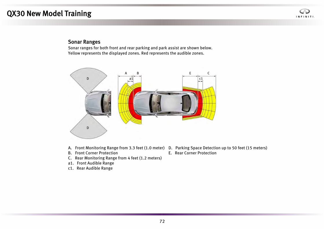
72
A. Front Monitoring Range from 3.3 feet (1.0 meter) B. Front Corner ProtectionC. Rear Monitoring Range from 4 feet (1.2 meters) a1. Front Audible Rangec1. Rear Audible Range
D. Parking Space Detection up to 50 feet (15 meters) E. Rear Corner Protection
D
D
A B E C
a1 c1
QX30 New Model Training
Sonar RangesSonar ranges for both front and rear parking and park assist are shown below. Yellow represents the displayed zones. Red represents the audible zones.

73
• Parallel or at right angles to the direction of travel.• Parallel to the direction of travel and are at least 5 ft. (1.5 m) wide.• Parallel to the direction of travel and at least 3.2 ft. (1.0 m) longer than your
vehicle.• At right angles to the direction of travel and at least 3.2 ft. (1.0 m) wider than
your vehicle.
The parking symbol (2) is displayed, with a left or right arrow, in the upper instrument panel whenever a suitable parking space has been detected, and remains displayed until the vehicle has been driven approximately 50 feet (15 m) away from it. The left (1) or right (3) arrows appear depending on the vehicle side of the parking space. Passenger side parking spaces are displayed by default. Parking spaces on the driver’s side are displayed only when the driver’s side turn signal is activated, and must remain on until the driver confirms IPA use. The assisted parking function is activated by simply coming to rest and selecting reverse. The ‘Start Park Assist’ message is displayed on the vehicle information display. The driver can select yes/no by pressing the steering wheel ‘OK’ or 'Back' button and and follow the on-screen prompts.
System DiagnosisCONSULT-III plus can be used to observe Data Monitor changes in system operation. Work Support allows a technician to check the functionality of individual sensors.
Sonar Control Unit ReplacementCONSULT-III plus requires a network connection to download the appropriate configuration data and vehicle specification. This data is then written to the sonar control unit in the normal fashion.
2
31
QX30 New Model Training
Intelligent Parking AssistIntelligent Parking Assist (IPA) is an ultrasound electronic parking aid that automatically identifies potential parking spaces that are either parallel, or at right angles to the direction of travel and on both sides of the vehicle. All suitable parking spaces are indicated in the upper meter and the vehicle information display. Active steering intervention assists parking and exiting a parking space. The driver remains responsible for road speed and braking operations.IPA is activated automatically when driving forward. The system is operational at speeds of up to approximately 19 mph (30 km/h). While in operation, IPA only detects parking spaces that are:

74
• Automatic Speed Control Device (ASCD)• Forward Emergency Braking (FEB)• Adaptive Brake Assistant (BA)
The steering column-mounted cruise control stalk (lever) is used to manage the automatic speed control and speed limiting functions.
1, 3, or 4 Turn ON and set speed
2. Set following distance (rotate to change)3. Store current speed or call up last stored speed
4. Decelerate and set5. Deactivate cruise control
QX30 New Model Training
Automatic Speed ControlAutomatic speed control is standard and works in combination with other vehicle safety and braking systems, when equipped.
1. Accelerate and set
NOTE: Switch shown above is for Intelligent Cruise Control. Automatic speed control switch functions the same without distance setting.

75
Long Range Radar
Long Range Radar AlignmentAn Intelligent cruise control (ICC) sensor is located behind the front Infiniti emblem in the radiator trim. The sensor contains:• Control Unit• Long Range Radar Sensor (LRR)
Detection range and frequency is as follows:• 100 feet (30 m) for a detection angle of 30°• 100 feet to 330 feet (30 m to 100 m) for a detection angle of 16°• 330 feet to 660 feet (100 m to 200 m) for a detection angle of 12°• Carrier frequency 77 GHzSensor alignment is required using CONSULT-III plus whenever the ICC sensor is removed, reinstalled, or replaced.Two methods of alignment are provided in the service manual. The SST below supports alignment.
SST J-51093 SST 1-20-2721-1-IF
QX30 New Model Training
The intelligent cruise control (ICC) system helps the driver sustain a set speed and distance to a preceding vehicle. If the preceding vehicle comes to a stop, the system brings the vehicle to a standstill. When the preceding vehicle accelerates from a standstill, ICC supports a return to acceleration by a single tap of a column switch or a reapplication of the accelerator pedal.
The system operates up to 125 mph (200 km/h).
Intelligent Cruise Control
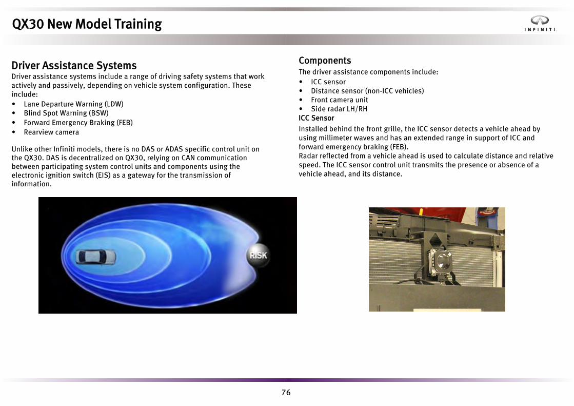
76
• Lane Departure Warning (LDW)• Blind Spot Warning (BSW)• Forward Emergency Braking (FEB)• Rearview camera
Unlike other Infiniti models, there is no DAS or ADAS specific control unit on the QX30. DAS is decentralized on QX30, relying on CAN communication between participating system control units and components using the electronic ignition switch (EIS) as a gateway for the transmission of information.
ComponentsThe driver assistance components include:• ICC sensor• Distance sensor (non-ICC vehicles)• Front camera unit• Side radar LH/RHICC Sensor
Installed behind the front grille, the ICC sensor detects a vehicle ahead by using millimeter waves and has an extended range in support of ICC and forward emergency braking (FEB).Radar reflected from a vehicle ahead is used to calculate distance and relative speed. The ICC sensor control unit transmits the presence or absence of a vehicle ahead, and its distance.
QX30 New Model Training
Driver Assistance SystemsDriver assistance systems include a range of driving safety systems that work actively and passively, depending on vehicle system configuration. These include:

77
Front Camera UnitThe front camera unit detects lane markers and is located above the windshield glass. It supports:
• Lane Departure Warning (LDW)• High Beam Assist (HBA)
Side Radar LH/RHInstalled behind the rear bumper, the side radars detect other vehicles in an adjacent lane in support of:• Blind Spot Warning (BSW)
QX30 New Model Training
Distance Sensor (non-ICC vehicles)
Installed in the back of the front bumper grille, it detects a vehicle ahead by using millimeter waves in support of FEB.Radar reflected from a vehicle ahead is used to calculate distance and relative speed. No adjustment is required if removed or replaced.

78
• Standard - Sensitivity increased (warnings issued earlier and more frequently)• Adaptive - Sensitivity reduced (warnings issued later and less often).
System limitations/requirements include:• From a vehicle speed of 37 mph (60 km/h)• Recognizable lane markings are present• Radius of curve is no less than 490 feet (150 m)• Track width between 8 to 15 feet (2.5 to 4.6 m)
1. Vehicle in lane2. Vehicle crosses outer lane -
steering wheel vibration initiated
3. Driver steers back into lane
Blind Spot WarningBSW monitors the rear and side areas of the vehicle using short range radar and if necessary, informs the driver that an intentional lane change (turn signal active) is not recommended. BSW can be switched On/Off via the vehicle information display menu. A visual warning is issued by the respective front door control module via the BSW warning indicator in the respective side mirror base.While relevant data is evaluated by all of the rear radar sensors, the warning output is the responsibility of the right rear bumper radar sensor. System limitations/requirements:• No under or over voltage• Engine running• Vehicle moving forward• Vehicle speed above 18 mph (30 km/h)
1 2 3
QX30 New Model Training
Lane Departure WarningThe front camera unit detects unintentional driving across lane markings and warns the driver by vibrating the steering wheel. Lane departure warning (LDW) can be switched ON/OFF via the vehicle information display menu.
The following operating modes are available for selection:

79
Front camera adjustment (LDW & HBA)Always adjust the camera aiming after removing and installing or replacing the front camera unit. Target dimension detail and aiming procedure are provided in the service manual.
1. Board2. String
3. Printed targetHeight of target center: 50.1 in. (1275mm)
1
2
3
QX30 New Model Training

80
Rearview camera
Vehicle width guiding line
Predictive course line
Rear bumper
Vehicle distance guiding line
Green: Approx 3 m
Green: Approx 2 m
Yellow: Approx 1 m
Red: Approx 0.5 m
QX30 New Model Training
Rearview cameraThe rearview camera displays the area behind the vehicle on the AV display control unit when reverse gear is selected.The camera system calculates guide lines based on the steering angle andother stored vehicle parameters.The steering angle is obtained via CAN from the steering column control unit. The predictive course lines can be turned off or on using the Infiniti controller.

81
• Driver/front passenger air bag (dual stage, adaptive)• Driver/front passenger side bags at front, with thorax/pelvis bag design• Driver knee bag• Passenger knee bag• Left and right curtain bags above both seat rows (additionally used as roll
over bags)• Front seat belts with emergency tensioning retractors and belt force
limitation• Rear seat belts on outer seats with emergency tensioning retractors and
belt force limitation• ISOFIX and top tether child seat anchors on the two outer seats in the rear
passenger compartment• Automatic child seat recognition air bag OFF indicator lamp• Front and rear seat belt status display
1. Curtain air bag module2. Seat belt buckle3. Passenger air bag module4. Knee air bag module5. BCM6. Combination meter (air bag
warning lamp)7. Steering column control module8. Driver air bag module9. Side air bag module10. Rear seat belt pretensioner
11. Rear door satellite sensor12. Front seat belt pretensioner13. B-pillar satellite sensor14. Front door satellite sensor15. Air bag diagnosis sensor unit16. Crash zone sensor17. Occupant classification system
control unit18. Occupant classification system
sensor
QX30 New Model Training
RestraintsQX30’s passive safety measures relating to pyrotechnics include:

82
• Monitoring of front, lateral, and rear crash sensors• Monitoring of internal rollover sensors where roll over protection is
required• Monitoring of seat belt fastening• Monitoring of passenger seat occupancy• Receipt and transmission of CAN network safety related information• Safety check and display of warning information• Deployment of seat belt pretensioners• Deployment of air bags• Deployment of main battery pyrofuse• Post-crash function including engine stop, fuel shut off, door unlock,
and hazard warning
System flexibility can accommodate up to ten separate external crash/impact sensors allowing up to ten air bags to be controlled, all of which is configurable with CONSULT-III plus. When replacing an air bag module however, it is important to note that there are two part numbers available, depending on if roll over protection is fitted.
Air Bag Control Unit ReplacementCONSULT-III plus procedures must be performed before and after replacement of an air bag control unit.
Crash/Impact SensorsTwo types of external crash/impact sensors exist, depending on position and application.G Sensor
• Front Crash Sensor (front chassis legs)• Side Crash Sensor (B pillars)• Rear Crash Sensor (air bag module)
Pressure Sensor
• Side Impact (front and rear doors)
QX30 New Model Training
Air Bag ModuleThe air bag module is positioned centrally in the vehicle directly under the center console. Its main responsibilities include:

83
PyrofuseThe pyrofuse is installed on the positive battery terminal. The fuse is deployed by the air bag module in the event of air bag deployment and cuts the 12V on-board electrical supply to the starter motor, and the connection to the alternator.
Service PointDisconnect the battery at the negative terminal in the normal manner. The pyrofuse connector should be removed using the same procedures as other pyrotechnic devices. Refer to service manual for detail. Do not discharge storage capacitors by disconnecting the negative cable and shorting to the positive cable.
QX30 New Model Training

84
• Seat not occupied• Seat occupied• Light weight (e.g. child seat)• Person detected
1. Passenger Air Bag Active 2. Passenger Air Bag Deactivated
1
2
The passenger air bag is automatically deactivated if the seat is not occupied or a child seat is fitted. The occupied signal is retained for a short time when pressure on the front passenger seat is relieved.
Zero Point Reset
The weight sensing calibration test tool SST J-51950 (shown above) must be used in conjunction with CONSULT-III plus to calibrate the air bag module weight sensing parameters when performing any of the following: • Seat cushion removal or replacement• Seat cover removal or replacement• Sensor mat removal or replacement• Seat heater removal or replacement• The front passenger seat is removed, or replaced
QX30 New Model Training
Front Passenger Seat Occupancy DetectionThe air bag module uses a silicone filled weight sensing pressure mat in the passenger seat base cushion to determine the following states depending on the weight classification measured:

85
1. Seat belt2. Reel3. Ball bearings
4. Track5. Torsion bar6. Retractor pyrotechnic
Torsion bar load limiter
1
2
3
6
5
4
QX30 New Model Training
Seat beltsSeat belt buckle switches are provided for both front seat positions to allow front seat belt status to be displayed on the instrument panel.
Pyrotechnic ball bearing type seat belt pre tensioners with torsion bar belt force
load limiters are fitted to the outer front and rear seats.
Pyrotechnic pretensioner
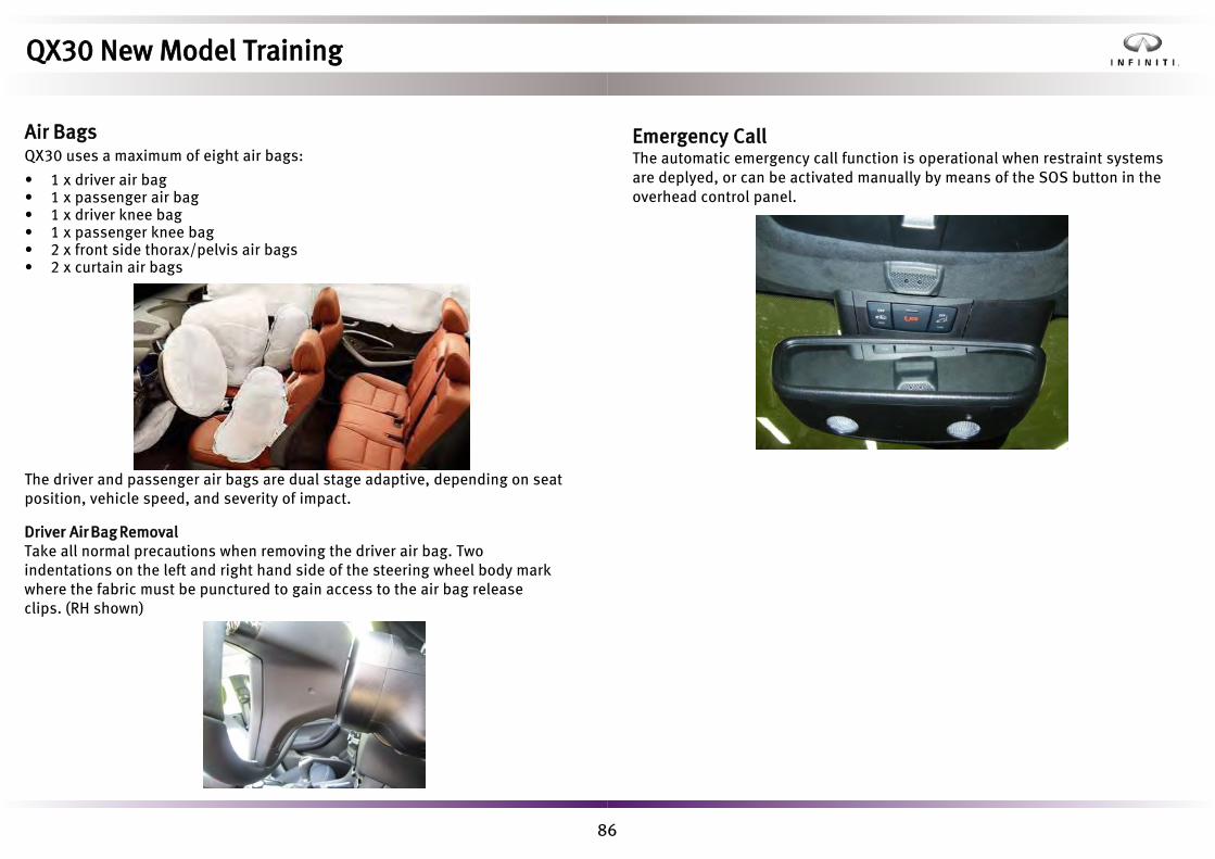
86
Air BagsQX30 uses a maximum of eight air bags:
• 1 x driver air bag• 1 x passenger air bag• 1 x driver knee bag• 1 x passenger knee bag• 2 x front side thorax/pelvis air bags• 2 x curtain air bags
The driver and passenger air bags are dual stage adaptive, depending on seat position, vehicle speed, and severity of impact.
Driver Air Bag RemovalTake all normal precautions when removing the driver air bag. Two indentations on the left and right hand side of the steering wheel body mark where the fabric must be punctured to gain access to the air bag release clips. (RH shown)
Emergency CallThe automatic emergency call function is operational when restraint systems are deplyed, or can be activated manually by means of the SOS button in the overhead control panel.
QX30 New Model Training

87
Refrigerant Circuit
The refrigerant circuit is the same regardless of system type. It is conventional in operation. Circuit main features include:• Condenser and evaporator• Variable swash plate compressor with magnetic clutch• High and low pressure circuit service/test points• Thermal expansion valve• PAG oil type specific to refrigerant usedAs with Q50, a double pipe heat exchanger consisting of a coaxial tube (tubewithin a tube) allows the refrigerant feed and return to flow close to each other.This provides additional refrigerant cooling, thus reducing the operating energyinput of the refrigerant compressor (increased system efficiency).
Outer Tube
Inner Tube
QX30 New Model Training
Heating, Ventilation and Air ConditioningThe QX30 heating, ventilation, and air conditioning (HVAC) system is modular in design and available as a manual or an automatic system. The air flow layout and ventilation outlets are shown below.

88
In-cabin Micro Filter
QX30 New Model Training
HVAC UnitA drain hose is attached to direct condensed moisture from the evaporator to the underside of the vehicle. Technicians must ensure this is attached correctly toprevent water ingress into the passenger compartment.
Air is drawn in via a fresh air/recirculation door and a single pipe blower. The blower motor is mounted separately from the housing by special rubberelements to minimize vibrations and reduce noise. The blower speed can be continuously varied with an energy-efficient, pulsed regulator. The in-cabin micro filteris accessed on the glove box side of the center stack.

89
Automatic Climate Control Features
• Selectable dual zone air conditioning with on/off button• Automatic temperature and fan speed adjustment with manual override• Automatic air distribution with manual override via four stepper motors• Additional rear center vent• Digital adjustment via buttons/selector wheels• Display of left/right specified temperature via central panel• Front and rear windshield defoggers• Automatic air recirculation• In-cabin micro filter with activated charcoal• Coolant circulation pump used to support coolant flow at low engine
RPM or when the residual heat function is being used• Additional control sensors:
• Evaporator Temperature Sensor• Refrigerant Pressure Sensor• Internal Temperature Sensor• Air Quality Sensor• Solar Sensor
1. LH Zone Temperature2. Auto Mode ON/OFF3. Windshield Defogger4. Manual Airflow Increase5. Manual Air Distribution6. Central display panel7. Air Recirculation ON/AUTO Switch
(LED off when in auto mode)
8. HVAC System ON/OFF Switch9. RH Zone Temperature10. MAX Cooling Switch11. Air Conditioning ON/OFF Switch12. Manual Airflow Decrease13. Rear Window Defogger14. Single/Dual Zone Switch
Control Panel While the InTouch center screen displays climate information, control is only performed via the control panel.
QX30 New Model Training

90
Air Quality SensorThis sensor provides information in support of the automatic recirculation function. It is sensitive to the following:• Carbon Monoxide (CO)• Nitrogen Oxides (NOx)• Outside dew point temperature• Relative humidity• Ambient temperatureIt is located adjacent to the interior ventilation air inlet, to the side of the plenum chamber.
QX30 New Model Training
Air Conditioning FilterRemoval of the glove box is not necessary. To replace the filter, simply
remove the right lower kick panel and carefully fold back the passenger
side carpet to reveal the interior relay/fuse box, auxiliary stop/start battery, and filter location. Two quick-release clips secure the filter cover. Remove and replace as shown.

91
Interior Temperature SensorFitted in the instrument panel, it is used for feedback to help maintain a consistent interior cabin temperature.
QX30 New Model Training
Outside Air TemperatureUsed to refine the climate control of the passenger compartment, it is fittedto the left side of the front bumper lower grill.

92
Eco Stop/Start FunctionInitially, the system prevents the engine from being stopped until the preselected interior temperature is reached. Once achieved however, if the interior temperature increases above the preselected value during subsequent stops, the air conditioning does not request a forced engine start in order to save energy, and the refrigerant compressor is not activated unless there is a risk of the windows fogging up. As a consequence, this can result in a reduced cooling output while the engine is stopped if the outside temperature is high. If this is not desired, the ECO stop/start function can be deactivated by pressing the ECO OFF button.
Auto Air Recirculation ModeTo prevent the windows from fogging up, the system automatically switches back to external ventilation in the following cases:• After 5 minutes when the refrigerant compressor is shut off• After 5 minutes if the outside temperatures is below approx. 44°F (7 °C)• After 30 minutes if the outside temperatures is above approx. 44°F (7 °C)
DiagnosisWhen performing diagnostics or talking to the customer, the following operational points are worth noting:• When switching the air conditioning OFF, there may be a delay before the
magnetic clutch disengages.• Changes in diffuser outlet noise may be experienced periodically when in
automatic recirculation mode.• When making manual mode changes with the IGN ON/ENG OFF, there may
be a delay before the changes take place when the engine has started.
QX30 New Model Training
Sunload SensorThe sensor is located in the center of the dash closest to the base of the windshield. It is used to trim the cabin temperature dependent on the vehicle’s position in relation to the intensity and position of the sun.

93
1. Vents2. Center Display3. Meters and Gauges4. Rotary Light Switch5. Electric Parking Brake6. Steering Wheel
7. Audio System8. Ignition Switch9. Heating and Air Conditioning10. Central Switch Panel11. Vehicle Information Display12. Glove Box
1. Turn Signal, Wiper, Washer,and High Beam Stalk
2. Steering Wheel Controls LH3. Ignition Switch (dash mounted
behind steering wheel)4. Steering Wheel Controls RH5. Rotary Lighting Switch and Fog
Lamp Switch
6. Electric Parking Brake7. Intelligent Cruise Control/ASCD
Stalk8. USB Connection Ports9. Transmission Shift Lever10. Double Front Cup Holders11. Infiniti Controller
1 2 3 4
8
910 11
7
5
6
1 1 3 11 2 1 1
4 5 6 8 7
9
10 12
QX30 New Model Training
Driver ControlsThe accompanying diagrams show the layout of the instrument panel andmain driver controls. This section takes a look at the functionality andservice aspects of the steering wheel combination switch, central switchpanel, and the rotary lighting switch.

94
QX30 New Model Training
Steering Wheel Combination SwitchThe switch internal functionality is similar to that of other Infiniti models, however on QX30 it has a built-in steering wheel angle sensor. If the combination switch is removed or replaced, relearning of the steering wheel center position is done automatically without CONSULT intervention. Externally, differences are limited to thepositioning and operation of its control stalks.

95
Rotary Lighting SwitchThe lighting switch has the following functionality:
• Parking lights• Side marker lights• Auto lights (OFF position when the ignition is off)• Headlights• Front fog lamp switch• Manual headlamp leveller (halogen headlamps)
Four versions are available depending on vehicle specification:
• Manual headlight leveller• Manual headlight leveller with front fog lamp switch• Automatic (LED) headlight leveller• Automatic (LED) headlight leveller with front fog lamp switch
Central Switch PanelFour variations of the central switch panel exist:
1. With hazard switch, ECO start/stop switch, passenger air bag On/Off LED,and anti-theft-protection indicator LED
2. As above (1) with seat heaters3. As above (1) with parking assist cancel switch4. As above (1) with parking assist cancel switch and seat heaters
NOTE: leaving in Park position for a very extended period may cause battery to discharge.
QX30 New Model Training

96
NAM
Black and white X
Color without ICC X
Color with ICC X
General Layout
1. Speedometer2. Vehicle Information Display3. Upper Information Display4. Tachometer
5. Engine Coolant Temperature Gauge6. Fuel Gauge
Speedometer
On vehicles with intelligent cruise control (ICC), the outer ring (2) of the speedometer (1) is divided into LED segments (3) that light up to indicate the available speed range when cruise control is activated.
A combination meter can be swapped between vehicles repeatedly while the total recorded distance is under 620 miles (1000 kms). After this distance has been achieved, the combination meter is locked to the vehicle.
The combination meter does not have immobilizer responsibilities.
1 2 3
56
4
1
2
3
QX30 New Model Training
Instrument PanelCombination meter versions exist depending on vehicle specification andtrim level, as follows.
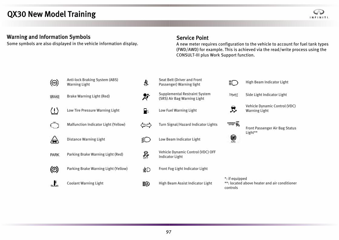
97
Warning and Information Symbols Some symbols are also displayed in the vehicle information display.
Service PointA new meter requires configuration to the vehicle to account for fuel tank types (FWD/AWD) for example. This is achieved via the read/write process using the CONSULT-III plus Work Support function.
mAnti-lock Braking System (ABS) Warning Light m
Seat Belt (Driver and Front Passenger) Warning light m High Beam Indicator Light
m Brake Warning Light (Red)m
Supplemental Restraint System (SRS) Air Bag Warning Light
mLow Tire Pressure Warning Light m Low Fuel Warning Light
m Side Light Indicator Light
mMalfunction Indicator Light (Yellow) m Turn Signal/Hazard Indicator Lights
mVehicle Dynamic Control (VDC) Warning Light
mDistance Warning Light m Low Beam Indicator Light
m Front Passenger Air Bag StatusLight**
m Parking Brake Warning Light (Red)m
Vehicle Dynamic Control (VDC) OFF Indicator Light
m
mParking Brake Warning Light (Yellow)
mFront Fog Light Indicator Light
mCoolant Warning Light m High Beam Assist Indicator Light
*: if equipped**: located above heater and air conditioner controls
QX30 New Model Training

98
Depending on the vehicle equipment levels, the driver can scroll between the following vehicle information display sub menus by repeatedly pressing the left or right steering wheel buttons:• Trip• Navigation• Audio• Assist• Service• SettingsPressing the OK button selects a sub menu, while pressing the up or down steering wheel buttons scrolls between the options within a sub menu. The owner’s manual provides more information regarding the vehicle configurable parameters within the vehicle information display menu options.
1
6
2
3
4
5
1j Permanent Display: depending on vehiclespecification: outside temperature or speed
2j Time
3j Text Field
4j Menu Bar
5j Drive Program
6j Shift Lever Position
Text Field 3j shows the selected menu or
sub-menu as well as display messages.
QX30 New Model Training
Vehicle Information DisplayThe instruments panel central display is used to convey driving information and vehicle set up parameters.

99
• LIN inputs to the driver’s door module• Hardwire outputs from the driver’s door module• CAN exchange of information with other vehicle control modules via either
EIS or BCM modules.
The front passenger door electrical architecture is similarly laid out.
Seat Switch
Door Lock Switch
Window Switch
Mirror Switch
Blind Spot Warning Switch
Door Grab Handle Light
Under Door Hazard Light
Door Opener Handle Level Light
Interior Lamps
DMFLDMFR
Actuator Power Window
Door Lock Motor
EIS
BCMInterior Mirror
(Dimmer)
EC-Glass(Dimmer)
Mirror Swing
Heater
Indicator Lamp (Mirror)
LIN
LIN
LIN
LIN
LIN
CANCAN
CAN
Hardwire
Hardwire
Hardwire
Hardwire
Hardwire
Hardwire
Hardwire
Hardwire
Har
dwire
To Other Units
QX30 New Model Training
Door ControlThe driver door electrical architecture regarding the operation of electric windows,mirrors, door lock control, and lighting is shown below and consists of:

100
• With super lock and blind spot warning• Without super lock and blind spot warning
Regardless of type, all door modules are software compatible with the following vehicle features:• 7DCT• Auto dimming• Electric folding mirrors• Seat memory• Ambient lightingCommunication architecture between the two front door modules is shownbelow.
Door Module Front Left (DMFL) Door Module Front Right (DMFR)
DMFL EIS DMFR
LIN
LIN
CAN CAN
DMFL EIS DMFR
LIN
LIN
CAN CAN
QX30 New Model Training
Door ModulesBoth front doors are equipped with a door module. Each is accessed by removingthe relevant door finisher. They are marked VL and VR to designate the appropriateside. Both modules are available as:

101
Electric Window Switches
• Power window switch in front passenger and rear doors.
Central Locking Switch
The switch is fitted to the driver door panel and additionally on the passenger side door panel.Pressing and holding the lock or unlock button until a bleep is heard switches the vehicle’s automatic locking feature ON or OFF without the use of the vehicle information display menu.
QX30 New Model Training
QX30 New Model Training
Door SwitchesThe front door switch operation is managed by the front door modules. Rear door switches are hard wired directly to the body control module (BCM).All electric window switches are all double detent to allow both specific positioning and one touch operation. Anti-pinch function is present on all electric windows.
Driver Door Switch PanelTo types of driver door switch panel exist depending on vehicle specification:
• Power window switch block with child lock and mirror adjustment switch.• Power window switch block with child lock, mirror adjustment switch, and
mirror folding function.

102
LightingTwo external lighting systems are available. • Halogen Headlamps• LED Headlamps
Halogen Headlamp SystemThe 60/55 W (H9) halogen front lighting system has manual adjustment. The front turn signal lamps utilize conventional PWY24W bulbs. All other external lighting is LED.
1. Side Turn Signal Lamp2. Parking Lamp/Daytime Running
Light/Position Lamp3. Parking Lamp/Daytime Running
Light/Position Lamp4. Headlamp (Hi/Lo)5. Front Turn Signal Lamp6. Front Fog Lamp
7. Tail Lamp8. Stop Lamp9. Rear Turn Signal Lamp10. Back-up Lamp11. License Plate Lamp12. High-mounted Stop Lamp
12
345
6
11
910
8
7
12
QX30 New Model Training

103
• Active Front Lighting System (AFS)• High Beam Assist (HBA)
1. Side Turn Signal Lamp2. Parking Lamp/Daytime
Running Light/Position Lamp3. Parking Lamp/Daytime
Running Light/Position Lamp4. Headlamp (Hi/Lo)5. Headlamp (Hi)6. Cornering Lamp
7. Front Fog Lamp8. Tail Lamp9. Stop Lamp10. Rear Turn Signal Lamp11. Back-up Lamp/Rear Fog
Lamp (Driver Side Only)12. License Plate Lamp13. High-mounted Stop Lamp
1
23456
7
13
12
1110
8
9
QX30 New Model Training
LED Headlamp SystemThe LED front combination lamps have automatic adjustment. With this system,all lamps are LED. System additions include:
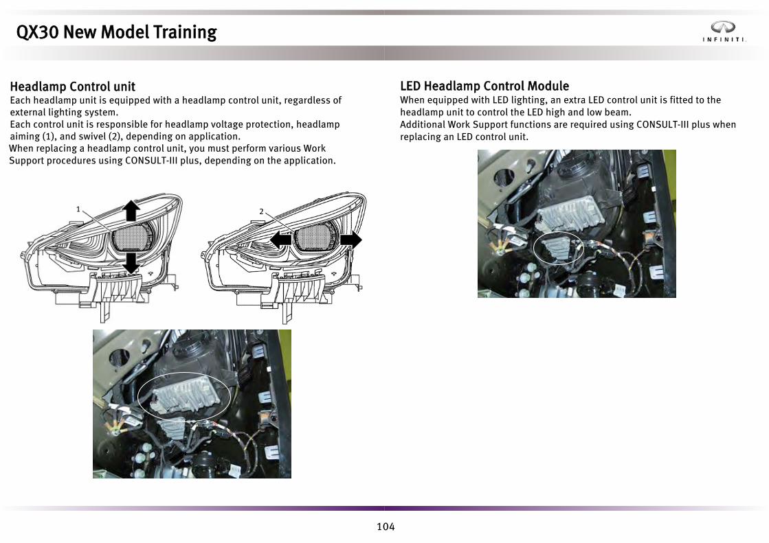
104
21
LED Headlamp Control ModuleWhen equipped with LED lighting, an extra LED control unit is fitted to the headlamp unit to control the LED high and low beam.Additional Work Support functions are required using CONSULT-III plus when replacing an LED control unit.
QX30 New Model Training
Headlamp Control unitEach headlamp unit is equipped with a headlamp control unit, regardless of external lighting system.Each control unit is responsible for headlamp voltage protection, headlamp aiming (1), and swivel (2), depending on application.When replacing a headlamp control unit, you must perform various Work Support procedures using CONSULT-III plus, depending on the application.

105
Lighting CircuitsThe basic halogen lighting circuit is shown below. Lighting request information is processed by the BCM and communicated to each front combination lamp unit. The combination meter displays the appropriate lighting selected.
Rotary Light Switch
Steering Column Control Module
Combination Switch
BCM
Front Combination Lamp
HFR Board
Bifuncation Board
Combination Meter
Cut-off Motor
Headlamp Hi/Lo
QX30 New Model Training
Auto LightsThe auto light system is managed by the BCM and can have the auto wipers linked to its function.The function automatically turns ON/OFF the exterior lamps (headlamp Lo/Hi, front fog lamp, position lamp, license plate lamp, and tail lamp) dependingon the outside brightness.

106
This final lighting circuit diagram is associated with the active front lighting system (AFS) and high beam assist (HBA) system. These systems are only available if the vehicle is equipped with LED front headlamp system.
Rotary Light
Switch
Light &Rain Sensor
Over Head Control Panel Control Unit
Steering Column Control Module
Combination Switch
Combination Meter
ECM
CAN Communication LineBCM
Headlamp Control
Unit
LED Headlamp
Control Module
Combination Meter
CAN Communication
Line
To Exterior Lamps
To Exterior Lamps
To Exterior Lamps
Front Combination Lamp
Rotary Light Switch
Steering Column Control Module
Combination Switch
Combination Meter
ECM
CAN communication line
Front Camera Unit
Headlamp Control Unit
LED Headlamp
Control Module
Combination Meter
CAN Communication
Line Headlamp Aiming Motor
To Exterior Lamps
Front Combination Lamp
Electronic Stability Program
Control Unit
BCM
QX30 New Model Training
For comparison, the LED lighting circuit also utilizes hard wire and CAN communication, however additional LIN communication is used internally between each combination lamp control unit.

107
• Active Curve Control – each headlamp swivels according to steering wheelinput and road speed.
• Cornering Lamp Control – additional area illuminated when cornering(requires indicator operation).
• Headlamp Automatic Aiming Control – automatic headlamp beam heightadjustment.
All of the above features require the following conditions to be met:• Engine running• Headlamp low beam selected• Vehicle being driven
Headlamp Automatic Aiming Control
Headlamp automatic leveling is required when equipped with LED headlamps. Suspension height sensors are fitted to right hand side suspension components, front and rear.Information from these sensors is sent to the LH headlamp control unit for headlamp aiming purposes. Sensor initialization is required in Work Support using CONSULT III plus when replacing a front combination lamp or when reinstalling/replacing a height sensor.
Active Curve Control Cornering Lamp Control
Front Rear
QX30 New Model Training
Active Adaptive Front Lighting SystemActive adaptive front lighting system (AFS) is controlled by each headlamp control unit and comprises the following features:

108
Bulb ReplacementFront lighting service access points are built into the front wheel inner wheel arch liners.
QX30 New Model Training
High Beam Assist SystemWhen the driver sets the lighting switch to high beam position, the high beam assist (HBA) system automatically switches the headlamp to the low beam when a vehicle ahead or an oncoming vehicle appears.The high beam assist system is controlled by a combination of the BCM and front camera unit.

109
Start Enable Clutch Pedal
Switch (M/T Models)
Clutch Pedal Switch
(M/T Models)
TCM(A/T Models)
Steering Column Control Module
Front Door Lock Assembly
(Driver Side)
Front Door Lock Assembly
(Passenger Side)
Left/Right Front Door Control Unit
Left/Right Front Door Control Unit
Hood Switch
Overhead Control Panel Control
Unit
Light & Rain Sensor
Washer Level Switch
ECM
Combination Meter Electronic Ignition Switch Control Unit
BCM
Front Wiper Relay
Front Wiper Hi/Lo Relay
Washer Pump
Front Wiper Motor
Hi
Lo
Light & Rain Sensor Serial Link
Light & Rain
Sensor Signal
Body CAN Communication 1
Door Open
Signal
Door Open
Signal
Clutch Status Signal (M/T Models) Shift Position Signal (A/T Models) Shift Position Signal
Ignition Switch Status Signal Combination Switch Status Signal Clutch Status Signal (M/T Models) Shift Position Signal (A/T Models)
Vehicle Speed Signal
Body CAN Communication 2
Powertrain CAN Communication Shift Position Signal
Chassis CAN Communication
Combination Switch Status Signal
QX30 New Model Training
WipersFront Wipers
The steering column control module detects the combination switch position and transmits the front wiper request signal to the BCM via CAN communication. The BCM controls both the front wiper relay and front wiper Hi/Lo relay. When in the auto wipe position, the infrared rain sensor detection information is forwarded to the BCM via a serial link.A hood open signal prevents wiper operation up to a road speed of approx. 4 mph (6 km/h) to eliminate damage.

110
Start Enable Clutch pedal
Switch (M/T Models)
Clutch Pedal Switch
(M/T Models)
TCM(A/T Models)
Steering Column Control Module
Front Door Lock Assembly
(Driver Side)
Front Door Lock Assembly
(Passenger Side)
Left/Right Front Door Control Unit
Left/Right Front Door Control Unit
Back Door Lock Assembly
Overhead Control Panel Control
Unit
Light & Rain Sensor
Washer Level Switch
PCM
Combination Meter Electronic Ignition Switch Control Unit
BCM
Fuse and Fusible Link Block 2
Rear Wiper Relay Washer Pump
Rear Wiper Motor
Light & Rain Sensor Serial Link
Light & Rain
Sensor Signal
Body CAN Communication 1
Door Open
Signal
Door Open
Signal
Ignition Switch Status Signal Combination Switch Status Signal Clutch Status Signal (M/T Models) Shift Position Signal (A/T Models)
Vehicle Speed Signal
Body CAN Communication 2
Powertrain CAN Communication Shift Position Signal
Chassis CAN Communication
Combination Switch Status Signal
Powertrain CAN Communication Clutch Status Signal (M/T Models) Shift Position Signal (A/T Models)
QX30 New Model Training
Rear WiperThe steering column control module detects the combination switch positionand transmits the rear wiper request signal to the BCM via CANcommunication. The BCM controls the rear wiper relay and washer pump.Rear wiper operation is linked to reverse gear selection, depending on a number of operation conditions being met.

111
Wiper Blade ReplacementThe wiper blade assembly can only be replaced as a complete assembly.
QX30 New Model Training
Spray Nozzle Hose HeaterIf the outside temperature is 41°F (5°C) or less, the spray nozzle hose heater prevents the washer fluid in the spray nozzles and the spray nozzle hose from freezing.
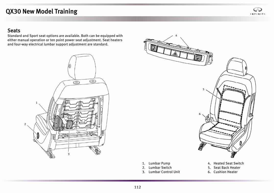
112
5
6
1. Lumbar Pump2. Lumbar Switch3. Lumbar Control Unit
4. Heated Seat Switch5. Seat Back Heater6. Cushion Heater
1
2
3
4
QX30 New Model Training
SeatsStandard and Sport seat options are available. Both can be equipped with either manual operation or ten point power seat adjustment. Seat heatersand four-way electrical lumbar support adjustment are standard.

113
Seat memory positions are stored in the relevant seat position control module. Linked external door mirror positions and reverse gear passenger mirror park positioning is stored in the driver seat position control module, however. The EIS acts as the gateway to allow information to flow between the front door modules and the seat position control modules.
Driver Seat Heater Filament
LH Outside Mirror
Mirror Position Switch
Heater Switch 3 x Stage Increase Option
Seat D
DMFL
Memory Switch M, 1, 2, 3
Mirror Position Sensor
CBC
Heater switch 3 x Stage Increase Option
Seat P Passenger Seat Heater
RH Outside Mirror
DMFR
Memory Switch M, 1, 2, 3
Mirror Position Sensor
Mirror Position Switch
DCT Shift Unit(on selecting reverse
causes passenger mirror to move in relation to curb)
Electrical Ignition Switch (EIS)
CAN CAN
CAN CAN
CAN
CAN
CAN
LIN LIN
LINLINLIN LIN
Hardwire
HardwireHardwire
Hardwire
Har
dwir
e
Har
dwir
e
QX30 New Model Training
Seat Position and MemoryDriver and passenger ten-point power seat adjustment option includes three position seat memory storage, activated via separate door mounted seat switch panels.

114
• Without heated front seats• Power seat with memory and seat heating (driver side)• Power seat with memory and seat heating (passenger side)
The automatic drive positioner system found on other Infiniti models, including entry/exit assist and I-key interlock function, is not currently included on QX30.
Seat HeatersThe three red indicator lights in each seat heater switch indicate the selected heating level. The system automatically switches between levels as follows:
• Level 3 to level 2 after approximately eight minutes• Level 2 to level 1 after approximately ten minutes• Level 1 to OFF after additional 20 minutes
If the vehicle battery voltage is too low, the seat heating function may be switched off.
QX30 New Model Training
Seat Control ModulesThree versions of the seat position control module are available, dependingon vehicle specification.

115
A. View with driver doorB. View with front door finisher removedC. View with center console assembly removedD. View with rear door finisher removedE. View with luggage side finisher lid removedF. View with luggage floor board removedG. View with back door panelH. View with back door inner finisher removed 1. Front Door Lock Assembly (Driver Side)2. Right Front Intelligent Key Door Handle
3. Electronic Ignition Switch Control Unit4. Combination Meter5. BCM6. Air Bag Diagnosis Sensor Unit7. Left Front Intelligent Key Door Handle8. Front Door Lock Assembly (Passenger Side)9. Rear Door Lock Assembly LH10. Fuel Filler Lid Lock Assembly11. Back Door Lock Assembly12. Window Antenna
13. Rear Door Lock Assembly RH14. Door Lock and Unlock Switch15. Front Door Control Module16. Front Inside Key Antenna17. Outside Key Antenna18. Intelligent Key Unit19. Rear Inside Key Antenna20. Back Door Opener Switch21. Remote Keyless Entry Receiver
QX30 New Model Training
SecurityComponent LocationsDoor lock control, engine start control and immobilizer component locations are shown below.

116
To remove a door lock, first remove the appropriate door finisher and drill out the rivets of the door module to gain access to the lock mechanism. A 7 mm drill is required.
Door Lock Tailgate Lock Fuel Filler Lock
Front and rear left hand door modules are shown on the following page.
Service PointPower electric window motors can be removed without removing the door module.
Note: Speaker replacement requires door module removal.
QX30 New Model Training
Door LocksElectrical door lock mechanisms are fitted to all four doors, the rear tailgate, and the fuel filler lid. The driver door is the only door lock fitted with a mechanical key cylinder.

117
Front Door Module
1. Rear Gasket2. Key Rod (Driver Side)3. Front Door Rear Sash4. Door Lock Assembly5. Torx Bolt6. Lock Knob Rod7. Door Lock Cover (Rear)8. Front Door Module9. Inside Handle
10. Door Lock Cover (Front)11. Inside Handle Cable12. Lock Knob Rod Connector13. Outside Handle Bracket14. Front Gasket15. Outside Handle Grip16. Outside Handle Escutcheon
Pawl
Vehicle Front
Rear Door Module
1. Rear Gasket2. Rear Door Rear Sash3. Door Lock Assembly4. Lock Knob Rod5. Torx Bolt6. Door Lock Cover (Rear)7. Rear Door Module8. Inside Handle9. Door Lock Cover (Front)
10. Inside Handle Cable11. Lock Knob Rod Protector12. Outside Handle Bracket13. Front Gasket14. Outside Handle Grip15. Outside Handle Escutcheon
Pawl
Vehicle Front
QX30 New Model Training

118
Fuel Lid AssemblyPulling hooks must be used to correctly remove the fuel lid base assembly.
1. Fuel Filler Lid Base Assembly2. Fuel Filler Lid Assembly3. Fuel Filler Lid Opener Actuator
4. Grommet
Pawl
31
3
4
To reinstall the door finishers, new rivets must be used with a commercial riveter.
QX30 New Model Training

119
Emergency Tailgate Release
QX30 New Model Training
Emergency Fuel Lid Lock ReleasePartial removal of the rear inner wheel arch liner allows access to the fuel lid release grommet.Removing the grommet allows screwdriver insertion to press against the release latch as shown.

120
Certain trim levels may have color accents on the key fobs.
Emergency Mechanical KeyThe release latch (1) allows removal of the emergency mechanical key.
1
2
1
2
Key Battery ReplacementInverting the emergency mechanical key and replacing it in the key body releases the key cover to reveal the battery.
1. Key Blade 2. Battery Cover
1
2
QX30 New Model Training
Door Lock Key ControlBoth remote central door locking (without Intelligent key) and keyless entryoptions (with intelligent key) are available. Regardless of the option, vehiclekey lock (1) and unlock (2) operations remain the same.

121
• Keyless (with intelligent key)• Key fob (without intelligent key)• Internal driver door lock and unlock switch
The central locking system features the following functionality:• Tailgate opening• Reminder function (one flash lock, two flash unlock)• Fuel filler lid lock/unlock• Selective unlocking*• Auto re-locking• Vehicle speed auto locking**• Airbag deployment vehicle unlock• Play (child) protection function*Press key fob lock and unlock buttons simultaneously for approximately fiveseconds to switch feature On/Off.**Press the appropriate driver door internal lock/unlock switch for approximately five seconds to switch feature On/Off.
Window AntennaKey ID Signal
Key ID
Key ID Signal
Key ID Signal
Remote Keyless Entry Receiver
Electronic Ignition Switch Control Unit
Intelligent Key Unit
SignalWindow Antenna
Remote Keyless Entry Receiver
Combination Meter
Air Bag Diagnosis Sensor Unit
Chassis CAN Communication
Air Bag Signal
Door Lock and Unlock switch
(for LHD Models)
Door Switch
Left Front Door Control Unit
Door Lock and Unlock Switch
(for RHD Models)
Door Switch
Right Front Door Central Unit
BCM
Door Switch
Fuel Filler Lid Switch
Back Door Opener Switch
Left Front Door Lock Actuator
Super Lock Actuator
Right Front Door Lock Actuator
Super Lock Actuator (for RHD Models)
Rear Door Lock Actuator LH/RH
Fuel Filler Lid Lock Actuator
Back Door Opener Actuator
(for RHD Models)
Body CAN Communication
Door Lock/Unlock Switch Signal
Door Switch Signal
Door Lock/Unlock Switch Signal
Door Switch Signal
Door Switch Signal
Fuel Filler Lid Open Signal
Back Door Opener Switch Signal
QX30 New Model Training
Central Locking SystemThe system electronically locks/unlocks the vehicle doors, tailgate, and fuel filler lid, and can be operated by the following methods:
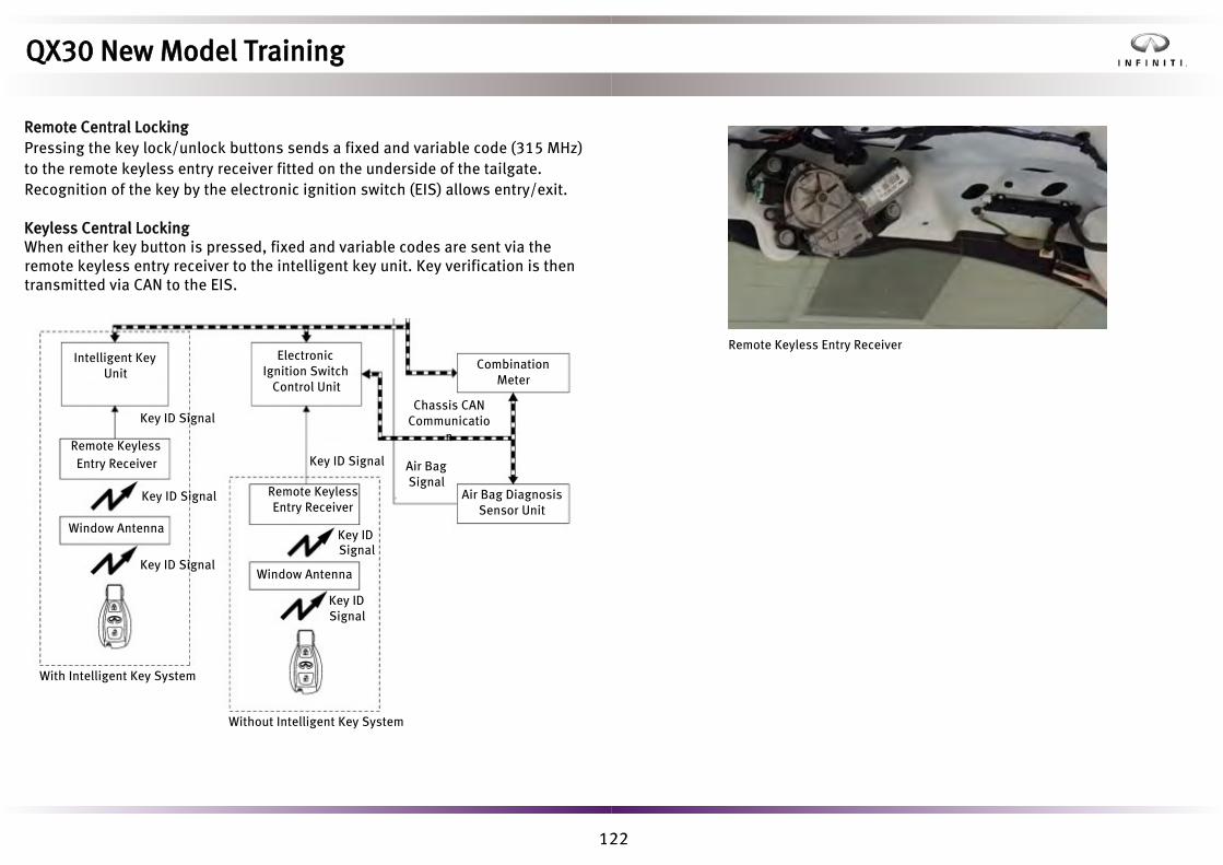
122
Intelligent Key Unit
Electronic Ignition Switch
Control Unit
Key ID Signal
Remote Keyless Entry Receiver
Remote Keyless Entry Receiver
Combination Meter
Air Bag Diagnosis Sensor Unit
Chassis CAN Communicatio
n
Air Bag Signal
Key ID Signal
Key ID Signal
Key ID Signal
Key ID Signal
Key ID Signal
With Intelligent Key System
Without Intelligent Key System
Remote Keyless Entry Receiver
QX30 New Model Training
Remote Central LockingPressing the key lock/unlock buttons sends a fixed and variable code (315 MHz) to the remote keyless entry receiver fitted on the underside of the tailgate. Recognition of the key by the electronic ignition switch (EIS) allows entry/exit.
Keyless Central LockingWhen either key button is pressed, fixed and variable codes are sent via the remote keyless entry receiver to the intelligent key unit. Key verification is then transmitted via CAN to the EIS.
Window Antenna
Window Antenna

123
Intelligent Key System The intelligent key system offers a keyless entry alternative to the remote key fob central locking/unlocking featured on the previous page.Additional components include:• Front door intelligent key door handles• Remote keyless entry receiverCapacitive intelligent key front door handles detect the presence of a key.• Grip (1) to unlock• Touch (2) to lock
The appropriate outside antennas receives the key identification. This signal is read by the window mounted remote keyless entry receiver.
Intelligent Key UnitThe intelligent key unit controls the intelligent key system, and is installed behind the luggage room left side finisher. If replacing the unit, it must be configured with CONSULT III plus using a network connection to download (write) the new configuration.
Each Front Intelligent Key Door Handle
Remote Keyless Entry Receiver
Electronic Ignition Switch Control Unit
Left Front Door Control Unit
Front Left Door Lock Actuator
Right Front Door Control UnitEach Inside/Outside
Key Antenna
Right Front Door Lock Actuator
Back Door Opener Switch
Rear Door Lock Actuator LH/RH
Back Door Opener Actuator
BCM
Intelligent Key Unit
Request Signal
Key ID Signal
Key ID Signal
Window Antenna
Key ID Signal
Key ID Signal
Back Door Opener Switch
Signal
Body CAN Communication
1 2
QX30 New Model Training
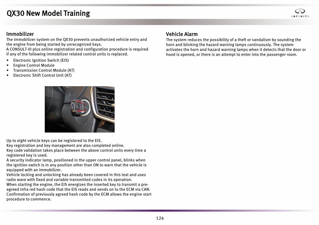
124
• Electronic Ignition Switch (EIS)• Engine Control Module• Transmission Control Module (AT)• Electronic Shift Control Unit (AT)
Up to eight vehicle keys can be registered to the EIS. Key registration and key management are also completed online.Key code validation takes place between the above control units every time a registered key is used. A security indicator lamp, positioned in the upper control panel, blinks when the ignition switch is in any position other than ON to warn that the vehicle is equipped with an immobilizer.Vehicle locking and unlocking has already been covered in this text and uses radio wave with fixed and variable transmitted codes in its operation.When starting the engine, the EIS energizes the inserted key to transmit a pre-agreed infra red hash code that the EIS reads and sends on to the ECM via CAN. Confirmation of previously agreed hash code by the ECM allows the engine start procedure to commence.
Vehicle AlarmThe system reduces the possibility of a theft or vandalism by sounding the horn and blinking the hazard warning lamps continuously. The system activates the horn and hazard warning lamps when it detects that the door or hood is opened, or there is an attempt to enter into the passenger room.
QX30 New Model Training
ImmobilizerThe immobilizer system on the QX30 prevents unauthorized vehicle entry and the engine from being started by unrecognized keys.A CONSULT-III plus online registration and configuration procedure is required if any of the following immobilizer related control units is replaced.

125
1. Windshield Glass Spacer*2. Windshield Glass*3. Windshield Glass Moulding*4. Electric Unit Bracket*5. Inside Mirror Base*6. Glass Primer7. Adhesive Painted Surface Primer
8. Roof Panel9. Glass Roof10. Cowl Top Cover11. Cowl Top Panel12. Front Pillar Garnish13. Body Side Outer Panel
* Windshield Glass Assembly Parts
Interior MirrorThe sensor unit in the mirror detects the brightness of the headlights of the vehicle behind and automatically adjusts to reduce the brightness.
The system does not operate when reverse gear shift signal and illumination signal are detected.
Auto Anti-Glare Inside
Mirror
Interior Illumination
BCM
Electronic Ignition Switch
Control Unit
Left Front Door Control Unit
(LHD Models)
Right Front Door Control Unit
(RHD Models)
Door Mirror (Driver Side)
Body CAN Communication
LIN Communication
Interior Illumination Signal
QX30 New Model Training
Glass and WindowsWindshield GlassPiano wire can be used to cut adhesive if a windshield cutter is not successful. Windshield glass should always be replaced with new glass after removal.

126
1. Door Mirror Cover2. Door Mirror Housing3. Power Folding Unit4. Bracket5. Actuator6. Glass Mirror7. Inner Cover8. Side Camera
9. Door Mirror Finisher10. Door Mirror Base Cover11. Puddle Lamp12. Door Mirror Gasket13. Door Mirror Base14. Side Turn Signal
Lamp Pawl
• Electric fold• Electric fold with camera• Electric fold with memory and camera
The mirror shown to the right is electric folding with memory and camera.
QX30 New Model Training
Door MirrorsThree types of door mirrors are available, depending on vehiclespecification. All door mirrors are heated and fitted with puddle lamps.
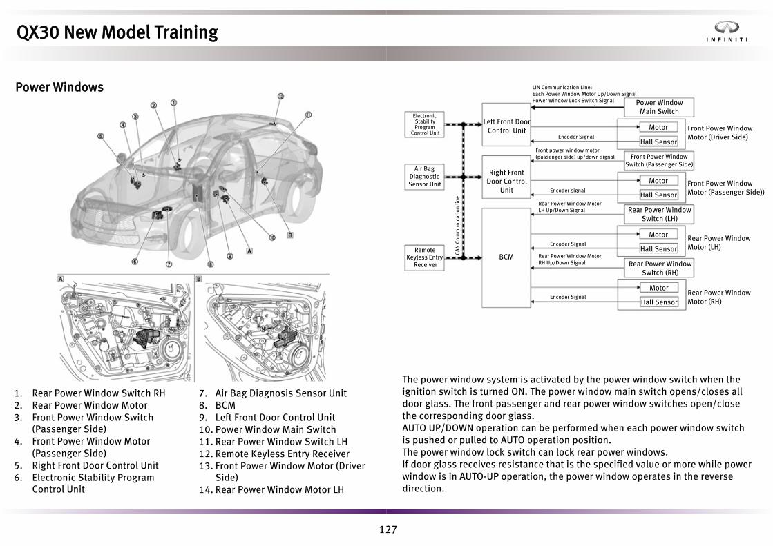
127
1. Rear Power Window Switch RH2. Rear Power Window Motor3. Front Power Window Switch
(Passenger Side)4. Front Power Window Motor
(Passenger Side)5. Right Front Door Control Unit6. Electronic Stability Program
Control Unit
7. Air Bag Diagnosis Sensor Unit8. BCM9. Left Front Door Control Unit10. Power Window Main Switch11. Rear Power Window Switch LH12. Remote Keyless Entry Receiver13. Front Power Window Motor (Driver
Side)14. Rear Power Window Motor LH
The power window system is activated by the power window switch when the ignition switch is turned ON. The power window main switch opens/closes all door glass. The front passenger and rear power window switches open/close the corresponding door glass.AUTO UP/DOWN operation can be performed when each power window switch is pushed or pulled to AUTO operation position.The power window lock switch can lock rear power windows.If door glass receives resistance that is the specified value or more while power window is in AUTO-UP operation, the power window operates in the reverse direction.
Electronic Stability Program
Control Unit
Air Bag Diagnostic Sensor Unit
Remote Keyless Entry
Receiver
Left Front Door Control Unit
Right Front Door Control
Unit
BCM
Power Window Main Switch
Motor
Hall Sensor
Front Power Window Switch (Passenger Side)
Hall Sensor
Hall Sensor
Motor
Motor
Rear Power Window Switch (LH)
Rear Power Window Switch (RH)
Front Power Window Motor (Driver Side)
Rear Power Window Motor (LH)
Rear Power Window Motor (RH)
Encoder Signal
Encoder Signal
Encoder signal
CA
N C
omm
unic
atio
n lin
e
Encoder Signal
Front power window motor (passenger side) up/down signal
Rear Power Window Motor LH Up/Down Signal
Rear Power Window Motor RH Up/Down Signal
LIN Communication Line:Each Power Window Motor Up/Down SignalPower Window Lock Switch Signal
QX30 New Model Training
Power Windows
Front Power Window Motor (Passenger Side))Hall Sensor
Motor
128
Rear Power Window LockWhen the power window lock switch is turned ON, it controls each rear power window switch and disables the operation of the power window by the rear power window switch.
Operation ConditionWhen all door glass AUTO-UP operation is performed, the anti-pinch function does not operate just before the door glass closes and is fully closed.
Pre-safe FunctionWhen the electronic stability program control unit detects operation of the ABS system, all power windows close, but a gap of 1.8 – 2.2 in (46 – 54 mm) is maintained to minimize the risk of injury.
Crash Deflation FunctionThe air bag diagnosis sensor unit transmits an impact detection information signal via CAN communication to the left front door control unit, right front door control unit, and BCM. These modules then actuate all power window motors downward. This creates a gap to allow the smoke generated during air bag inflation to disperse.
QX30 New Model Training
LIN CommunicationThe power window main switch and left front door control unit transmit and receive LIN communication.LIN communication transmits the power window main switch operation signals to the left front door control unit.
Power Window Auto OperationAUTO UP/DOWN operation can be performed when each power window switch is pulled or pressed to AUTO operation position. The Hall sensor detects the movement of the power window motor and transmits the hall sensor signal to the power window switch while the power window motor is operating.The power window switch reads the changes of the hall sensor signal and stops AUTO operation when the door glass is at the fully opened/closed position.

129
Rear Window DefoggerGlass Mirror
Door Mirror Defogger
• Ignition ON• No under or over voltage detected• Consumer shutoff not active
Rear Window Defogger Connector
Within the door mirror heating function, there are a number of sub operations:
• Manual ON/OFF function - Air conditioning module reads rear windowdefogger switch status and activates rear screen and door mirror heating viathe rear window defogger relay.
• Automatic switch-on function – To assist in engine cold start warm up cycle,the ECM requests defogger action to electrically load the engine (15 min).
• Determining switch-on duration function – Air conditioning moduledetermines duration of defogger operation (2-26 min) based on outside airtemperature and vehicle speed.
• Auto stop shutoff function – Defogger is switched off temporarily when theengine stops as part of the operation of the stop/start system.
• Consumer shutoff function – if excessive battery discharge is detected, thedefogger function may be switched off temporarily (lamp remains lit).
Heated Washer SystemSpray nozzle/hose heater operating conditions: • Engine running• Outside temperature is 41°F (5°C) or less
The spray nozzle and spray nozzle hose heater prevent the washer fluid in the spray nozzles and the spray nozzle hose from freezing.
JMLIA7063GB
QX30 New Model Training
Heated Rear GlassThe rear window and door mirror heating functions operate in tandem and require the following:

130
Paint Type Color Code
Solid Black Obsidian KH3
Metallic Majestic White QAB
Metallic Blade Silver KY0
Metallic Graphite Shadow KAD
Metallic Malbec Black GAC
Metallic Magnetic Red NAJ
Metallic Chestnut Bronze CAN
Metallic Ink Blue RBN
Metallic Liquid Copper NAX
BodyThe use of high strength and ultra-high strength steel accounts for over 60% of the bodyshell construction. This saves weight while improving safety and crash protection. Panel materials include:
• Steel - Body construction. Door, trunk, roof, and side panels• Aluminium - Sculptured hood• Lightweight plastic - Front and rear bumpers, inner wheel arches, door
mirror housings• Glass roof - OptionalThe mechanical tailgate is double strut damped and supports electric lock operation.
QX30 New Model Training
PaintQX30 paint is applied by a physical vapor deposition process that is completelynew to Infiniti. It is considered the highest quality, most durable paint processcurrently available and provides a blemish free finish. At launch, the bodyexterior colors and codes include:

131
Rear Side View
Particular attention has been paid to the air flow and noise emanating from
under the hood.
Front Side View
Front Wing/Door Shut Baffle
• Plastic insert• Close fit provides barrier to airborne noise from
engine and front wheel arch area• LHS shown
Hood Hinge/Front Wing Baffle
• Plastic insert• Foam backed•
•
Close fit provides barrier to airborne noise fromengine and front wheel arch area
Incorrect fitment can cause external door paneldamage
• Door assembly must be removed from its hinges toreplace
• LHS shown
Hood Sound Deadening
QX30 New Model Training
Noise, Vibration and Harshness (NVH)Much attention has been made to minimize the intrusion of outside road and powertrain noise into the passenger compartment. Brown/beige components below are NVH and grey are primarily aerodynamic.

132
A special metal plating process for the front Infiniti emblem allows the radar waves of the Intelligent Cruise Control (ICC) sensor to pass through the badge. This removes the unsightly need for a visible transmitter and is a first for Infiniti. Use of high quality materials accentuate the progressive styling further.
Satin chrome-plated trim is used instead of plastic chrome trim found on competitors.There is a consistent use of black lacquer trim on many exterior elements.
Infiniti signature grille hints at a bridge reflected in water creating a pattern that is not symmetrical.The hood flows up and over projecting a wave action that channels wind for aerodynamic efficiency.
The rear quarter is non glass black lacquer with a satin chrome finish.
QX30 New Model Training
StylingOverall QX30 styling is marked by dramatic curves and dynamic lines to make an emotional statement.
On Sport models, sills are body color coded to visually lower the stance.
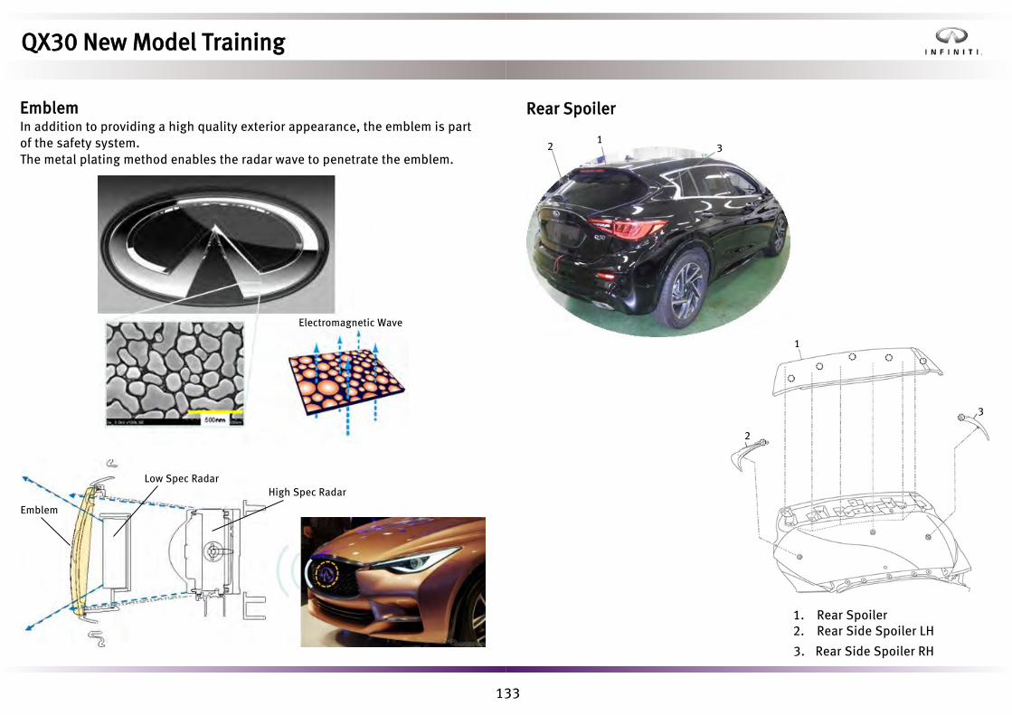
133
Electromagnetic Wave
Low Spec Radar
Emblem
High Spec Radar
Rear Spoiler
1. Rear Spoiler2. Rear Side Spoiler LH
3. Rear Side Spoiler RH
21
3
1
2
3
QX30 New Model Training
EmblemIn addition to providing a high quality exterior appearance, the emblem is partof the safety system.The metal plating method enables the radar wave to penetrate the emblem.

134
• Visually check clips for deformation and damage. Replace with new clips ifnecessary.
• Check that clips and pawl are accurately aligned with the portions on dashside finisher and center pillar lower garnish, and then install by pressing in.
Back Door
1. Back Door Hinge2. Back Door Striker3. Stud Ball4. Back Door Stay5. Back Door Stay Bracket6. Bumper Rubber
7. Bumper Rubber Bracket8. Back Door Panel9. Back Door WeatherstripA. Center Mark B. Seam
1
9A
2
8
34
5
67
B
QX30 New Model Training
Kick PlateWhen removing the outer kick plate, always use a removal tool that is made of plastic to prevent damage.Before installation, take the following precautions:
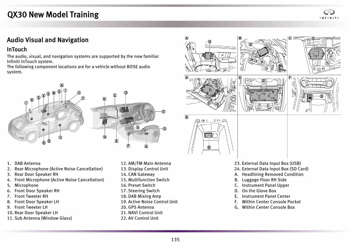
135
1. DAB Antenna2. Rear Microphone (Active Noise Cancellation)3. Rear Door Speaker RH4. Front Microphone (Active Noise Cancellation)5. Microphone6. Front Door Speaker RH7. Front Tweeter RH8. Front Door Speaker LH9. Front Tweeter LH10. Rear Door Speaker LH11. Sub Antenna (Window Glass)
12. AM/FM Main Antenna13. Display Control Unit14. CAN Gateway15. Multifunction Switch16. Preset Switch17. Steering Switch18. DAB Mixing Amp19. Active Noise Control Unit20. GPS Antenna21. NAVI Control Unit22. AV Control Unit
23. External Data Input Box (USB)24. External Data Input Box (SD Card)A. Headlining Removed Condition B. Luggage Floor RH SideC. Instrument Panel UpperD. On the Glove BoxE. Instrument Panel CenterF. Within Center Console Pocket G. Within Center Console Box
QX30 New Model Training
Audio Visual and NavigationInTouchThe audio, visual, and navigation systems are supported by the now familiar Infiniti InTouch system.The following component locations are for a vehicle without BOSE audio system.

136
With BOSE, the main additions are a sub woofer (1) and amplifier (2) fitted in the spare wheel well.
Display Control UnitThe display control unit controls the Infiniti InTouch screen and integrates the following functions:• Display• Bluetooth® moduleThe display control unit can store applications in the built-in memory byconnecting a cell phone via Bluetooth® communication or USB connection.
Display Screen Size 8-inch Wide VGA (152.4 x 91.44 mm)
Number of Pixels 800 x 480 Pixels
Drive Type TFT Active Matrix
Touch Panel Detection Firm/Glass Capacitive
Capacity (for Application Software) 512 MB
Bluetooth®
ModuleBluetooth®
AudioCompliant Communication Type
Wireless Connection
Bluetooth®
Communication
Hands-free Phone
Other Functions Voice Recognition Function
QX30 New Model Training

137
AV Control UnitAV control unit controls the audio system of Infiniti InTouch.
Amplifier Output (Models without BOSE) 40 W x 4 ch
CD Drive Playable Disc CD-ROM
CD-R
CD-RW
Playable Format MP3
WMA
AAC
Text Display Function
ID3/WMA/AAC Tag Artist Name
Album Title
Song Title
QX30 New Model Training
NAVI Control UnitNAVI control unit controls the navigation system of Infiniti InTouch.It integrates a gyro sensor and acceleration sensor, and calculates the vehicle position by combining the vehicle speed signal, reverse signal, and location information received from the GPS antenna.Map data is obtained from the SD card that is inserted in the external data input box (SD card slot).

138
External Data Input (USB)External data input box (USB) comprises 2 USB ports. External devices can be connected and can send signals to the display control unit via USB communication.
Active Noise Control Unit
The active noise control unit includes the following functions:• Active Noise Cancellation• Active Sound Enhancement• Diagnosis function with CONSULT-III plus
CAN communication lines connected to the active noise control unit are used for the active sound enhancement and diagnosis function with CONSULT-III plus.
QX30 New Model Training
External Data Input (SD Card)External data input box (SD card) records the map data from the SD card, and is then used by the navigation system.

139
Active Noise Cancellation
With BOSEThe front and rear microphones are used for the active noise cancellation system. The power is supplied from the BOSE amp to the microphone, transmitting sound signals to the BOSE amp during active noise cancellation.
Without BOSEThe front and rear microphones are used for the active noise cancellation system. The power is supplied from the active noise control unit to the microphone, transmitting sound signals to the active noise control unit during active noise cancellation.
Active Sound EnhancementDuring driving, active sound enhancement improves the quality of engine sound heard in the vehicle by producing a sound via the speakers according to engine speeds.The active noise control unit calculates the frequency, quality, and volume of engine sound from engine speed signal, engine torque signal, accelerator pedal position signal, and vehicle speed signal, and transmits the sound signal to AV control unit.When the AV control unit receives the sound signal from active noise control unit, it transmits the sound signal to each speaker.The AV control unit mixes the sound signal received from active noise control unit with the sound from audio, etc., and transmits the sound signal to each speaker.
QX30 New Model Training

140
1. Start the engine.2. Turn the audio system OFF.3. Touch the Settings icon to
enter the settings menu screen.
4. Press the seek/track up switch at least three times (within 15 seconds after the settings menu screen displays). If the self- diagnosis mode does not start after pressing the seek/track up switch more than four times, press the Menu switch again.
5. Touch the screen in the area shownin the illustration for three secondsor more.
6. The fault diagnosis initial screen isdisplayed, and then eitherSelf Diagnosis or Confirmation/Adjustment can be selected.
Details of these menu options are shown on the following page.
QX30 New Model Training
On-board DiagnosisThe InTouch display control unit is the only control unit on QX30 that has a self- diagnosis capability.Activation of the on-board diagnosis is similar to the InTouch fitted to Q50.
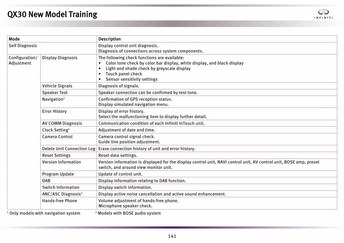
141
Mode Description
Self Diagnosis Display control unit diagnosis.Diagnosis of connections across system components.
Configuration/Adjustment
Display Diagnosis The following check functions are available:• Color tone check by color bar display, white display, and black display• Light and shade check by greyscale display• Touch panel check• Sensor sensitivity settings
Vehicle Signals Diagnosis of signals.
Speaker Test Speaker connection can be confirmed by test tone.
Navigation1 Confirmation of GPS reception status. Display simulated navigation menu.
Error History Display of error history.Select the malfunctioning item to display further detail.
AV COMM Diagnosis Communication condition of each Infiniti InTouch unit.
Clock Setting1 Adjustment of date and time.
Camera Control Camera control signal check. Guide line position adjustment.
Delete Unit Connection Log Erase connection history of unit and error history.
Reset Settings Reset data settings.
Version Information Version information is displayed for the display control unit, NAVI control unit, AV control unit, BOSE amp, preset switch, and around view monitor unit.
Program Update Update of control unit.
DAB Display information relating to DAB function.
Switch Information Display switch information.
ANC/ASC Diagnosis2 Display active noise cancellation and active sound enhancement.
Hands-free Phone Volume adjustment of hands-free phone. Microphone speaker check.
1 Only models with navigation system 2 Models with BOSE audio system
QX30 New Model Training

142
Navigation SystemThe navigation system can be operated with the preset switch, multifunction switch, and display control unit.
Refer to the owner’s manual for additional details.
QX30 New Model Training
Around View MonitorIncorporated in the InTouch system around view monitor (AVM) is the familiar system seen on other Infiniti models.
AVM Control UnitThe AVM control unit is located in left side of the luggage room.