2017 deq-8
TRANSCRIPT
2017 DEQ-8MONTANA STANDARDS FOR SUBDIVISION STORM WATER DRAINAGE

Major Changes
New Rules
Updated Circular
New Spreadsheets

New Rules – ARM 17.36.310
“Exempt Plan” moved from rule to circular and named the
“Simplified Plan”
PE Design required for:
Six or more lots
Lot proposed for use other than a single living unit with > 25% impervious
area
Maintenance plans required for all designs
Exemption for lots located within a 1st or 2nd class municipality or an
MS4 (form available here: link)
Renewal for PE designs if rules and circulars haven’t changed

Updated Circular
Improved Layout
Table of Contents (interactive)
List of Tables and Figures
Bookmarked PDF for easier navigation
Available here: link
Updated Circular
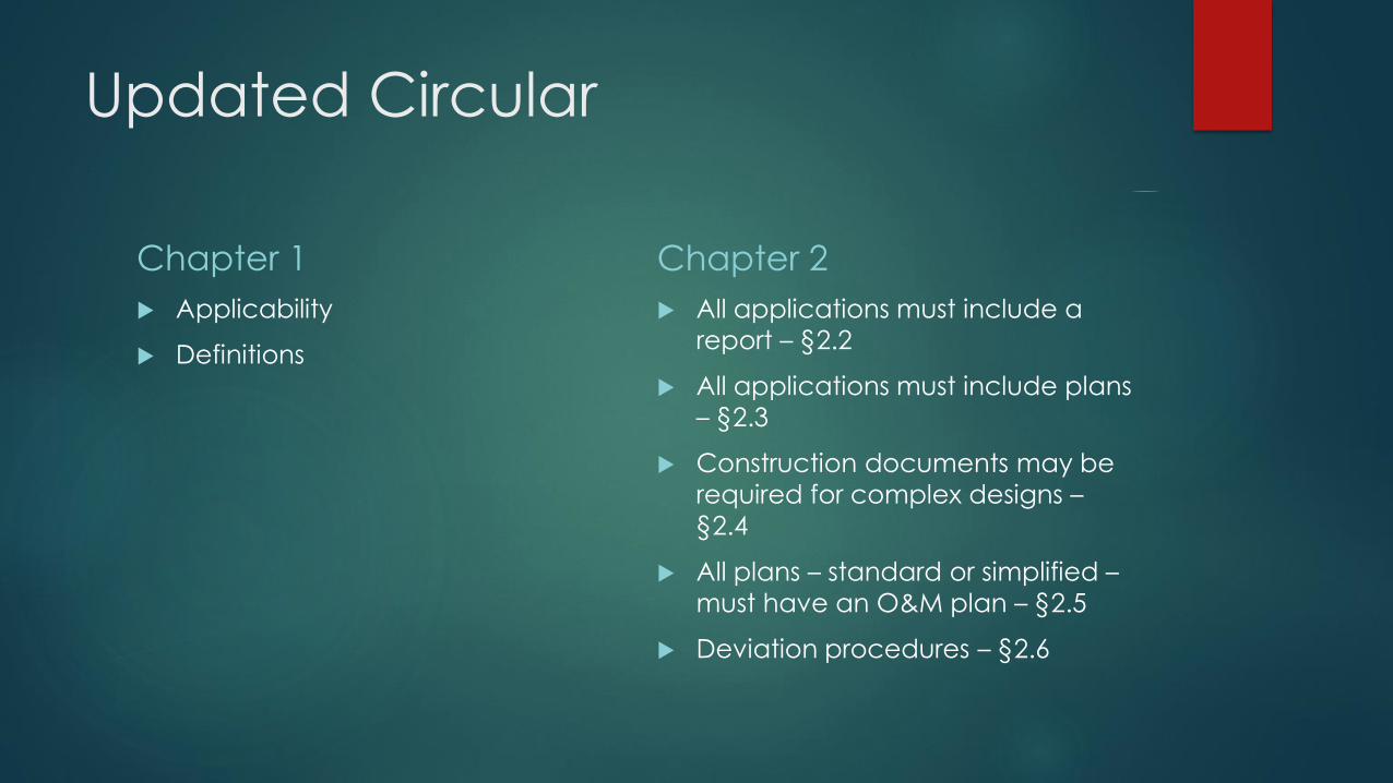
Chapter 1
Applicability
Definitions
Chapter 2
All applications must include a
report – §2.2
All applications must include plans
– §2.3
Construction documents may be
required for complex designs –
§2.4
All plans – standard or simplified –
must have an O&M plan – §2.5
Deviation procedures – §2.6

Updated Circular
Chapter 3 – Design Criteria
Simplified Plan – §3.2
Slope < 3%
Impervious area ≤ 25%
No change in historic runoff
No flow between lots
Design storm = 100-year
Standard Plan – §3.3
Post-development flow cannot
exceed pre-development flow for
the 2-year storm
Cannot overtop roads or
driveways for the 10-year storm
Cannot flood homes or drainfields
for the 100-year storm

Updated Circular
Chapter 3 – Design Criteria
Initial Storm Water Facility – §3.4
Must be sized to infiltrate,
evapotranspire, and/or capture for
reuse the post-development runoff
generated from the first 0.5 inches
of rainfall on impervious areas.
𝑉 =0.5∗𝐴𝑖𝑚𝑝
12𝑖𝑛𝑐ℎ𝑒𝑠
𝑓𝑡
V = minimum volume (ft3)
Aimp = total impervious area (ft2)
Pre- and Post Development
Conditions – §3.5
Clarifies
when the entire pre-development
condition should be considered
unimproved.
the procedure for rewrites.
situation where post-development
impervious area is unknown.

Updated Circular
Chapter 3 – Design Criteria
Rainfall Intensity – §3.6
Derived from the 24-hour storm duration:
Hydrometeorological Design Studies Center’s Precipitation Frequency Data Server (NOAA Atlas 2), B.
Data for select sites in Appendix A.
IDF curve at the time of concentration; or
Other sources approved by the reviewing authority.
Acceptable Methods– §3.7
Variety of methods in Appendix B
“Other methods may be used
upon approval by the reviewing
authority.”

Updated Circular
Chapter 3 – Design Criteria
Storm Water Volume – §3.8
Pre- and Post-development
conditions.
Simplified Plan – based on the 100-
year storm event.
Standard Plan – based on the 2-
year storm event.
Peak Flow – §3.9
Simplified Plan – may not alter historic runoff patterns outside the boundaries of the lot.
Standard Plan
Onsite Drainage Basin
Pre-Development Peak Flow for the 2-year storm event
Post-Development Peak Flow for 2-year, 10-year, and 100 year storm event
Offsite Drainage
Peak Flow for the 2-year, 10-year, and 100-year storm event

Updated Circular
Chapter 4 – Conveyance
Structures
Clarifies that impacts from
sediment deposition and erosion
must be addressed.
Conveyance structures must be
designed to convey post-
development peak flow
Cannot overtopping roadways or
driveways during a 10-year storm
event
Cannot flood buildings or drain
fields during a 100-year storm
event.
Describes three common types of
conveyance structures:
Open Channels
Storm Sewers
Culverts
Includes design criteria for each.

Updated Circular
Chapter 5 – Retention &
Detention Facilities
Retention facilities:
Must be sized for the difference
between the pre- and post-
development runoff volumes,
No consideration for infiltration
No designed outlet
Must include the volume of the initial storm water facility.
Side slopes must be no steeper
than 3 to 1 and must be stabilized.
Should not hold runoff for > 72
hours.
Detention facilities:
May not be used in simplified plans.
Must capture runoff and release at a flow rate ≤ the 2-year pre-development peak flow rate
Must include minimum volume requirement for an Initial Storm Water Facility as either infiltration or retention.
Should not hold runoff for > 72 hours.
Engineered outlet must be designed to reduce erosive velocities.

Updated Circular
Chapter 6 – Infiltration
Facilities
Infiltration facilities:
Must include minimum volume
requirement for an Initial Storm
Water Facility as either infiltration or
retention.
Must be sized in accordance with
Appendix C (infiltration rates and
testing procedure).
Should be sized to drain in 48
hours.
Lawns and landscaping areas
proposed as infiltration facilities
must be sized using the
appropriate runoff coefficient,
curve number, or other factor
consistent with the proposed land
use and as designated by the
selected design method in
accordance with Appendix B.
Updated Circular
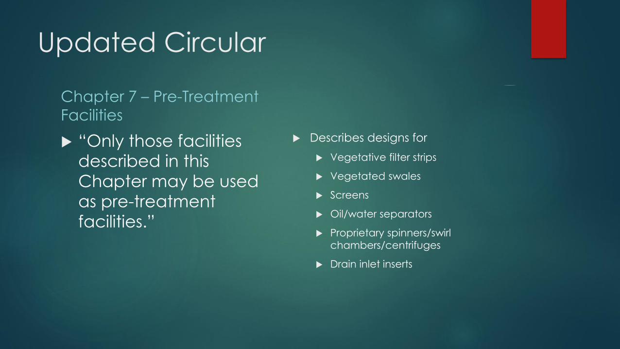
Chapter 7 – Pre-Treatment
Facilities
“Only those facilities
described in this
Chapter may be used
as pre-treatment
facilities.”
Describes designs for
Vegetative filter strips
Vegetated swales
Screens
Oil/water separators
Proprietary spinners/swirl
chambers/centrifuges
Drain inlet inserts
Updated Circular
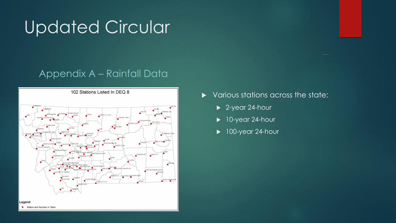
Appendix A – Rainfall Data
Various stations across the state:
2-year 24-hour
10-year 24-hour
100-year 24-hour

Updated Circular
Appendix B - Acceptable
Hydrologic Models & Tc
Appendix B.1 – Methods
Rational Method
TR-55
Storage-Indication Routing
Changes to Rational Coefficients
paved or other hard surface areas — 0.90
gravel areas — 0.80
undeveloped areas — 0.20
lawns or other landscaped areas — 0.10
Intensity (i) must be determined
using:
Tabulated rainfall data in
Appendix A.
Location specific Intensity-
Duration-Frequency (IDF) curve
time period = Tc
minimum Tc is 5 minutes.
For multiple sub-drainage areas, the longest Tc must be selected.
IDF curves for selected areas are available from the Department.

Updated Circular
Appendix B - Acceptable
Hydrologic Models & Tc
Modified Rational Method 𝑉 = 𝑇𝐷 ∗ 𝑄
V = Volume (ft3)
Td = Storm Duration (min. of 3600 seconds)
Q = Peak flow rate (cfs)

Updated Circular
Appendix B - Acceptable
Hydrologic Models & Tc
Appendix B.2 – Time of
Concentration (Tc)
Includes equations
Sheet Flow
Shallow Flow
Longest Tc must be selected if
there are multiple drainage areas.
Appendix B.3 – Computer Models
Hydraflow extensions for AutoCad,
HEC-1, WINTR-55, WINTR-20, and
SWMM
When using computer models:
Minimum Tc = 5 minutes
i determined using an IDF curve for
time = Tc
For multiple sub-drainage areas,
the longest Tc must be selected
Provide computations and
assumptions
Graphic inflow-outflow
hydrographs
Provide schematic (node)
diagrams

Updated Circular
Appendix C - Infiltration
Appendix C.1 – Design Infiltration
Rate
Appendix C.2 – Encased Falling
Head Test
Includes instructions on the
procedure

Updated Circular
Appendix D – Detention
Outlet Structure Equations
D.1 – Circular Orifices
D.2 – Weirs
Appendix E – Conveyance
Structure Equations
E.1 – Chezy-Manning Formula
E.2 – Curb and Gutter
E.3 – Storm Sewer Velocities
(table)
Appendices H – M Examples
Initial Storm Water Facility
Simplified Plan
Standard Plan – Retention Facility
Standard Plan – Infiltration Facility
Standard Plan – Detention Facility
Standard Plan – Conveyance
Facility

Updated Circular
Appendix OAppendix N

Spreadsheets

Spreadsheets