2017 cobb county traffic signal specifications · note: all general ... the cobb county traffic...
TRANSCRIPT
SECTION FIVE
COBB COUNTY TRAFFIC SIGNAL
SPECIFICATIONS

COBB COUNTY DOT
TRAFFIC SIGNAL
SPECIFICATIONS
OCTOBER 2017

2
Table of Contents
Section 647 – Traffic Signal Installation 4
Section 687 – Signal Timing 35
Section 925 – Traffic Signal Equipment 36
Section 935 – Fiber Optic System 91
Section 936 – Closed Circuit Television (CCTV) 113
Section 939 – Communication and Electronic Equipment 131
GENERAL PROVISIONS FOR INSTALLATION OF TRAFFIC CONTROL EQUIPMENT
1.1 PURPOSE – The purpose of this specification is to set forth the requirements and terms for signal installations in Cobb County, Georgia. All traffic signal equipment shall conform to the Cobb County Traffic Signal Specifications. All signal installations shall conform to the Georgia Department of Transportation specifications unless otherwise noted in these specifications. Where differences occur, this specification shall take precedence.
NOTE: All general provisions contained within these specifications shall apply to all sections.
1.2 EQUIPMENT – For all County Department of Transportation (Operations) Countywide Unit Price contracts, Cobb County will supply the following items: traffic signal cabinet, controller, monitor, cabinet base, tech pads, vehicle signal heads with LEDs, pedestrian signal heads with countdown inserts, pedestrian pushbuttons, pedestrian signs and mounts, fiber optic cable, strain poles, mast arms, pull boxes, video or radar detectors and all accessories, loop detectors, load switches and flashers. The contractor shall supply all other items, unless otherwise specified in the signal plans. For Developer funded traffic signal installations, Georgia Department of Transportation projects or County Department of Transportation roadway projects, all traffic signal equipment shall be furnished by the signal contractor that is performing the installation.
NOTE: All signal installations and materials shall conform to the current Georgia Department
of Transportation Specifications Edition, Cobb County DOT Traffic Signal Specifications and
the Cobb County Master Contract Section 3. Where differences occur, the Cobb County
Traffic Signal Specifications and the Cobb County Traffic Signal Installation Specifications
shall take precedence.
1.3 COMPETENCY OF BIDDERS – The Department may refuse any Contractor Proposals to bid on work based on past performance, to include work performed for the Department which was substandard or behind schedule.
1.4 CONTRACTOR/BIDDER
1.4.1 Contact Person – The bidder shall furnish the name and phone number(s) of a customer service representative that will serve as a liaison for Cobb County to address all equipment and
3
installation problems. It is the responsibility of this person to provide answers to all
questions pertaining to the equipment and installation being provided. If the contact person cannot answer a particular question, it is their responsibility to obtain an answer from an appropriate source. If equipment needs to be repaired or replaced, the contact person is responsible for making arrangements for returns and deliveries. All correspondence shall be through the contact person, unless otherwise agreed upon by Cobb County.
1.4.2 Alternate Contact – When the primary contact person will be unavailable for more than 24 hours (vacations, illness, etc.), Cobb County must be furnished with the name and phone number of an alternate contact given all responsibilities of the primary contact.
1.5 SUBCONTRACTOR – Any individual, firm, corporation, or combination thereof to which the Contractor with the written consent of the Department sublets any part of the Contract. The Department reserves the right to reject a proposed traffic signal subcontractor based on past performance, to include work performed for the Department which was substandard or behind schedule.

4
Revised for Cobb County June 23, 2015
Section 647 – Traffic Signal Installation
647.1.03 Submittals
Submit to the Cobb County Signal Design Engineer, signal material specifications information on all materials proposed for use on the project.
Written approval is required from the Cobb County Signal Design Engineer prior to beginning any work on the project.
A. Review
For all submittals, the Cobb County Signal Design Engineer’s review of the material should be completed within thirty (30) days from the date of receipt of the submission unless otherwise specified. The Cobb County Signal Design Engineer will advise in writing, as to the acceptability of the material submitted.
The Cobb County Signal Design Engineer will review all material submittals for fiber optic communications equipment and materials used on the project. The material review should be completed within thirty (30) days from the date of receipt of the material submission unless otherwise specified. The Cobb County Signal Design Engineer will advise in writing as to acceptability of materials to be used on the project.
Any item or items may be partially or totally rejected in which case, modify the submittal as required and resubmit within fifteen (15) days. At this time, the review and approval cycle described above begins again.
B. Submittal Costs
Include the costs of submittals within the price paid for individual bid items. No additional compensation will be made.
C. Steel Strain Pole, Concrete Strain Pole or Steel Pole Certification
Instruct the supplier or manufacturer of the strain poles or steel poles with traffic signal mast arms to submit a certification, including mill certificates to:
Cobb County Department of Transportation 1890 County Services Parkway Marietta, Georgia 30008
Include the following in the certification:
• A statement that the items were manufactured according to the Specifications, including the Specification subsection number
• Project identifier
Instruct the supplier or manufacturer to send copies of the transmittal letter to the Cobb County Signal Design Engineer. Refer to subsection 647.3.03.C.
Prepare Shop Drawings and related signal strain pole design calculations. Provide “bending moment at yield” to determine the foundation size according to the signal strain pole foundation drawings. Submit all Shop Drawings and related signal strain pole design calculations to the Cobb County Signal Design Engineer for review and approval. Obtain written approval prior to pole fabrication and installation. Pole design calculations shall be stamped by a Professional Engineer.
Show all dimensions and material designations of the designs on the drawings. See Section 501 for the certification procedure for poles and anchor bolts.
D. Signal Item Certification
Submit four (4) copies of material catalog product numbers and descriptions to the Cobb County Signal Design Engineer. Reference the project identifier and Specification subsection number for the following traffic signal items:
• Signal heads
• Mounting hardware
• Controllers
• Cabinet assemblies
• Detectors
• Monitors
• Cable
• Load switches
• Blank-out signs
• Lane use signals

5
• Preformed cabinet bases
• Other related signal equipment
• Fiber Optic Cable
E. Test Results Submittal
Submit the results of the testing of the following items to the Cobb County Signal Inspector upon request:
• Loop Detector Testing
• Interconnect Cable Testing (Fiber)
• Controller and Cabinet Testing
• Any other operational testing required by the Cobb County Signal Design Engineer
F. Mast Arm Pole Chart
For locations with mast arm pole installations, submit a “Mast Arm Pole Chart” for review and approval by the Cobb County Signal Design Engineer. The “Mast Arm Pole Chart” shall also include a sketch on an 8½-inch x 11 in (216 mm x 297 mm) sheet of paper showing the following:
• Curb lines
• Location of mast arm pole based on utility information. (Final location of mast arm pole must meet the criteria for setback from the road as specified in the Roadside Design Guide by AASHTO and in the Standard Detail Drawings)
• Distance from both adjacent curbs to mast arm pole
• Distance along mast arm from pole to curb and from curb to each proposed signal head
• Directional arrow
• Street names
• Position of Luminaries
647.2 Materials
647.2.01 Delivery, Storage, and Handling
A. County-supplied Equipment
For projects where traffic signal equipment is to be supplied by the Cobb County Department of Transportation, obtain County supplied traffic signal equipment from the Cobb County D.O.T. Signal Shop, 1890 County Services Parkway, Building 11 Marietta, Georgia 30008 unless directed otherwise by the Signal Plans:
1. Contact the Cobb County Signal Design Engineer by phone or correspondence within one week after receiving the Notice to Proceed and arrange for a location to pick up the signal equipment.
2. Sign Cobb County DOT’s Equipment/Material Pick-Up Form to accept delivery of the County-supplied equipment from Cobb County DOT’s Traffic Signal Equipment Warehouse.
3. Inspect the equipment to ensure that it is operating properly and perform any operational tests within ten (10) calendar days after receiving the equipment.
4. Before installation, and within ten (10) calendar days, certify to the Cobb County Signal Design Engineer in writing that the County-supplied equipment was received in good condition.
5. Notify the Cobb County Signal Design Engineer in writing if the County-supplied equipment is defective. The Cobb County Signal Design Engineer will replace the defective County-supplied equipment.
6. If no written dissent is received after ten (10) calendar days or if equipment is installed in the field, the Cobb County Signal Design Engineer will consider this equipment to be satisfactory and accepted.
7. The Contractor shall supply new equipment to replace County-supplied equipment that is damaged by the Contractor.
B. Signal Equipment
See Section 925 of the GDOT Standard Specifications and/or Cobb County DOT Specification for signal equipment specifications.
The signal equipment, components, supplies, or materials used in traffic signal installation may be sampled and tested if not previously approved by Cobb County DOT.
Test according to the Specifications and the Sampling, Testing, and Inspection Manual using one or more of the following methods:
• Have the supplier or manufacturer use their facilities and furnish Cobb County DOT with the test results.
• Provide independent laboratory test results indicating compliance with Cobb County Specifications referenced in Subsection 647.1.02, “Related References”, of this document.
• When testing by Cobb County is required, supply the item to Cobb County DOT. Acceptance of materials tested does not waive warranties and guarantees required by the Specifications.

6
C. Cable
Use cable that conforms to Section 680, Section 925, and the appropriate IMSA, NEMA, or UL Specifications for the wire or cable.
Obtain pole attachment permits required by local utility companies or pole owners to allow joint use for signal cable, hardware, or other auxiliary devices.
D. Interconnect Communications Cable
The interconnect cable (communication cable) links the master controller, the field controllers, and sensors. Follow these guidelines:
1. Use fiber optic interconnect cable for all new interconnected signal systems. See Section 935 for fiber optic cable information, specifications and installation and testing techniques.
2. Use copper cable only as directed by the Cobb County Signal Design Engineer or where specifically shown in the Plans. Refer to Section 647.3.05, “Construction”, of this document for installation.
E. Messenger Cable
Use cable that conforms to ASTM A 475 Siemens-Martin grade or better with Class “A” coating. The messenger is used to support cable indicated in the Plans as overhead cable. Use lashing wire to attach the cable.
• Before erecting the messenger strand, determine the suspension strand length to span the distance between the poles.
• Run the messenger strand from structure to structure without splicing.
• The maximum allowable sag is five percent (5%) of one-half of the longest diagonal distance between the signal poles.
• Calculate attachment points for the messenger strand at the signal pole according to the Plan detail sheet.
F. Fiber Optic Cable
Use fiber optic cable that complies with Section 935. Use GDOT approved materials, and utilize GDOT and fiber optic cable manufacturer recommended installation methods, practices and techniques for installation, storage and termination of fiber optic cable.
• Use minimum 24 fiber, single mode fiber optic cable, for communications unless otherwise specified in the plans.
• Submit fiber optic cable manufacturer supplied product information on materials to be used for review for Specification Section 935 for compliance.
• Before erecting the messenger strand, determine the suspension strand length to span the distance between the poles.
• Run the messenger strand from structure to structure without splicing.
• The maximum allowable sag is five percent (5%) of one-half of the longest diagonal distance between the signal poles.
• Calculate attachment points for the messenger strand at the signal pole according to the Plan detail sheet.
• For underground installation, utilize materials and techniques approved by the Cobb County Signal Design Engineer and in conformance with Subsection 647.3.05.M and detail sheets for conduit and pull box installations. Underground fiber optic cable installation shall include wire/cable for utility detection and in compliance with project detail sheets.
G. Conduit on Structures
Use rigid metallic materials for all exposed conduit for cabling. Use metallic conduit on the exterior of signal poles and other structures and to house signal conductors for the entire length from the weather head on the pole to the interior of the cabinet (see Subsection 647.3.05X).
647.3 Construction Requirements
Refer to Subsection 107.07 of the Specifications regarding proper conduct of The Work.
647.3.01 Personnel
The contractor shall provide the following personnel at all times on the job site: at least one person able to speak conversational English and at least one technician with an IMSA Level II Certification. For the definition of a qualified electrician, see Subsection 755.1.01.
647.3.02 Equipment
Use machinery such as trucks, derricks, bucket vehicles, saws, trenchers, and other equipment necessary for the work and approved by the Cobb County Signal Inspector prior to installation operations.
647.3.03 Preparation
Utility Permits

7
A. Deleted
B. Deleted
C. Utility Location
1. Adjustment
Prior to ordering signal poles, locate utilities and adjust the location of poles, where necessary, to minimize utility conflicts. Obtain approval from the Cobb County Signal Design Engineer or Signal Inspector for any deviation from the Plans. Determine the final length of mast arms based on any field adjusted pole locations. The Cobb County Signal Design Engineer shall approve final location.
2. Clearance
When installing aerial cable of any type, ensure that overhead clearance and separation requirements conform to local utility company standards and the NEC. Refer to the Standard Details Drawings for further information on utility clearances.
3. Attachment Height
All Fiber Optic Cable and/or loop leads will be lashed to the messenger cable and shall be attached above the
phone and cable TV attachments on utility poles.
4. Pre-emption
When traffic signal pre-emption is used, coordinate with the railroad, fire department or any other agency that uses pre-emption to obtain pre-emption output and route output cable to the signal controller operating the intersection to be pre-empted. Obtain all permits and approval for crossing at grade or grade separated railroad facilities.
647.3.04 Fabrication
General Provisions 101 through 150.
647.3.05 Construction
Contractors shall schedule and attend a pre-construction meeting with the Cobb County Signal Design Engineer and Signal Inspector before commencement of signal installation or modification. Contractors and their employees shall sign the log-in sheet, located inside the cabinet anytime that they enter the traffic signal cabinet.
A. Acquiring and Disposing of Equipment
Do not modify the signal equipment, design, and operation without the Cobb County Signal Design Engineer’s written approval.
All traffic signal equipment removed or replaced shall be returned to Cobb County Department of Transportation Signal Shop, 1890 County Services Parkway, Building 11 Marietta, Georgia 30008 unless otherwise noted in the Plans or as directed by the Cobb County Signal Design Engineer.
B. Traffic Signal Equipment Modification and Removal
Upon modification of any existing traffic signal equipment, responsibilities for maintenance, operations and response to traffic signal malfunctions become the responsibility of the contractor. The provisions of Section 647.3.07, “Contractor Warranty and Maintenance”, shall apply.
1. Remove existing signal equipment that is not used in the final installation when the new signal equipment is operational.
Carefully remove equipment to minimize damage and retain it in its original form. This equipment may include:
• Steel poles including the foundation down to 2 feet (600 mm) below ground level finished grade
• Timber poles
• Traffic signal cabinets including contents, cabinet base and work pads
• Original signal heads including span wire support
• Other equipment not retained in the final installation
Salvage the equipment as directed in the Plans or as directed by the Cobb County Signal Design Engineer
2. If the Plans specify delivery of salvaged equipment to the Cobb County DOT, 1890 County Services Parkway, Building 11, Marietta, Georgia 30008, provide an inventory list and deliver the salvaged equipment in a timely manner to the Signal Warehouse between the hours of 8:00am to 2:30pm or arrange a mutually agreeable delivery time with the Cobb County Warehouse Technician (770-528-4379) twenty-four (24) hours in advance.

8
3. Replace traffic signal equipment that the Cobb County Signal Design Engineer determines has been damaged or destroyed during installation or modification of the traffic signal, at no expense to Cobb County. Replace with new material.
4. If the Cobb County Signal Design Engineer finds that the existing material to be relocated is unsatisfactory, replace with new material. The costs will be paid for as Extra Work. Include the removal costs of all equipment, including salvaged equipment, in the cost of the overall bid price submitted.
5. Remove old signal heads by the end of the day that the new signal equipment is placed in operation. Remove
all other signal equipment within seven (7) days after operations of the newly operational equipment, or
within thirty (30) day burn-in period commencement. 6. THE CONTRACTOR IS REQUIRED TO MAINTAIN VEHICLE DETECTION WITHOUT
INTERRUPTION FOR ALL TRAFFIC SIGNAL PHASES DURING CONSTRUCTION OF THE
PROJECT. APPROVED VIDEO DETECTION SHALL BE USED FOR PRESENCE DETECTION AND
APPROVED VIDEO OR MICROWAVE DETECTION SHALL BE USED FOR PULSE DETECTION.
TEMPORARY POLES MAY BE REQUIRED TO SUPPORT THESE DETECTION DEVICES DURING
PROJECT CONSTRUCTION.
C. Auxiliary Cabinet Equipment
Provide auxiliary cabinet equipment or special purpose equipment with connecting harnesses, if necessary, or as shown in the Plans or Standard Detail Drawings.
1. Install the equipment in its associated cabinet. Extraneous wiring may be necessary to install the equipment. Additional cabling shall be enclosed in rigid, galvanized conduit and neatly secured.
2. Connect the auxiliary equipment to its cable harness, or insert it in pre-mounted racks or sockets.
D. Signal Controllers
Furnish and install approved microprocessor controllers at the locations shown in the Plans or as directed by the Cobb County Signal Design Engineer. All equipment furnished shall comply with Section 925,”Traffic Signal Equipment”.
1. Identify the controller and other auxiliary equipment by serial number and model. These numbers shall agree with previously approved catalog submittals.
2. Assemble the controller, cabinet, and auxiliary equipment to provide the operational sequence shown in the Plans and future operations specified.
E. Cabinet Assembly
1. Location
When placing the cabinet, choose a location that:
a. Protects maintenance personnel from vehicles when servicing the equipment. b. Allows the front panel door of the controller to open away from the intersection for view of signal indications
while servicing or performing cabinet work. c. Does not block a sidewalk or passageway and complies with Federal regulations for Americans with
Disabilities Act (ADA) clearance requirements. d. Is located away from the roadway or curb line to prevent vehicular damage to the cabinet. e. Is not located within drainage areas or installed in areas likely to collect and hold surface water.
Relocate the cabinet to avoid conflicts from proposed reconstruction projects, commercial driveways, etc. within the right-of-way at the Cobb County Signal Design Engineer’s discretion.
2. Erection
Install and level traffic signal controller cabinets at locations shown in the Plans and/or as directed by the Cobb County Signal Design Engineer.
a. Install cabinets to conform to the Standard Detail Drawings. Install pole or base-mounted as indicated in the Plans.
b. Seal base-mounted cabinets to their base using silicone based sealer. Pliable sealant used shall not melt or run at temperatures as high as 212 ºF (100 ºC).
c. Prefabricated bases
• When installing a signal cabinet without an external batter cabinet, provide a prefabricated base according to the plans that meets the following specifications: 1) Use a prefabricated base with the following dimensions: 26” x 36” x 18”. The opening for the signal
cabinet shall be 21” x 15”. 2) Use a prefabricated base with the following dimensions: 40” x 44” x 24”. The opening for the signal
cabinet shall be 21” x 15” and the opening for the external battery cabinet shall be 16” x 6”. Cover and seal the opening for the future external battery cabinet with a blank sign.

9
• When installing a signal cabinet with an external battery cabinet, use a prefabricated base with the following dimensions: 40” x 44” x 24”. The opening for the signal cabinet shall be 21” x 15” and the opening for the external battery cabinet shall be 16” x 6”.
d. Install technician pad in front and rear of the controller cabinet door. See standard details for pad information. e. Install a layer of coarse gravel with a minimum depth of 18-inches below the cabinet base. Extend the coarse
gravel layer 6-inches beyond edges of the cabinet base. f. Provide a 1/4–inch galvanized wire mesh between the gravel base and the bottom of the signal cabinet base.
3. Field Cabinet Wiring
All wiring shall be neat and secured and comply with NEC, NEMA, and Table 647-1, Table 647-2, Table 647-3 and Table 647-4 of this Specification.
a. Cut field cabinet wiring to the proper length plus an additional 4 feet and organize it in the cabinet.
• Use at least No. 6 AWG wire on conductors between service terminals and the “AC+” terminals to signal light relays, and buss terminals.
• Use at least No. 6 AWG wire on terminal connections to light neutral. b. Install split lug nuts at all terminal connections. c. Do not use splices inside the controller cabinet, base, or conduit. d. Do not use solid wire, except grounding wire. e. Supply the cabinets with cabinet wiring diagrams, schematic drawings, pin assignment charts, and manuals for
circuits and components. Store these documents in the cabinet in a resealable, weatherproof container.
NOTE: It shall be the responsibility of the contractor to complete all wiring of the cabinet and to ensure that
everything is labeled. All cabinets and controllers shall be tested prior to being placed into operation at the project
location and the Contractor shall submit a letter and/or e-mail documenting the date and time of cabinet testing to the
Cobb County Signal Inspector before Cobb DOT will apply for power to the traffic signal.
F. Signal Monitors
Furnish signal monitor equipment as follows:
1. Mount signal monitors in a rack with appropriate connectors to attach to the wiring harness. 2. Program the monitor card according to the signal operation indicated in the Signal Plans before placing the
installation in flash or stop-and-go operation. 3. Configure and equip the signal monitor to monitor all red signal indications. Ensure that the red output for
unused or vacant load bays or output slots is jumpered to 120 V AC+.
G. Power Disconnect
Install a power disconnect box at each intersection as shown in the Standard Detail sheets. Install service cables from disconnect box and terminate as specified on the controller cabinet-wiring diagram.
All traffic signal cabinets or any type of equipment being powered by GreyStone Power Company Shall include the following:
• Separate 8 ft. timber (4 x 4) post installed near the power pole with a meter base mounted to the maximum height of 72 inches and a minimum of 48 inches from final grade
• Power disconnect installed between the meter base and the equipment being powered within the same distances as the meter base
• Stub up the conduit from the meter base beside the power pole so the power company can run a “U” guard down the pole from their transformer to the top of the conduit
• Install a pull string from the open end of the conduit to the meter base
When installing power for GreyStone Power Company on a timber pole installation using Cobb County’s poles:
• Run a 1” ridged riser up the pole on the cabinet corner and install a meter base at the above mounting height
• Run the 1” ridged riser up the pole to the power disconnect with a weather head at the top of the power disconnect
• The top of the weather head shall be mounted a minimum height of 22’ from grade with the power disconnect mounted a maximum distance from the top of the weather head of 36”
• Install an eye bolt 6” above the weather head.
NOTE: All signals, all-way flashers, vehicle approach warning flashers, school flashers, and any other equipment that
is being powered by AC voltage shall have a disconnect installed before applying for power. The AC Power shall run
in a separate 1” rigid riser and conduit from the cabinet to the nearest power pole with a disconnect box attached in
close proximity to the top of the riser.

10
H. Flashing Beacon
Furnish and install the flashing beacon controller at the locations shown in the Plans and/or as directed by the Cobb County Signal Design Engineer. Install it as a complete unit (solid state flasher and cabinet with time clock, if applicable) and ensure that it conforms to this Specification.
I. Loop Detector Systems
Install and test loop detector systems according to NEMA Standards Publication TS 1-1983, Section 15, Inductive Loop Detectors, subsequent revisions (except as shown in the Plans), details, notes, and this Specification.
Ensure that loop detectors are complete and fully operational before placing the signal in stop-and-go operation.
1. General Installation Requirements Each loop must refer to Table 647-6 and Table 647-7 of this Specification for specific turns of conductor. Do not place a portion of the loop within 3 feet (1 m) of a conductive material in the pavement such as manhole covers, water valves, grates, etc. a. Install pull boxes, condulets, and conduits before beginning loop installation. b. Ensure that the ambient pavement surface temperature in the shade is at least 40 ºF (5 ºC) before placing
sealant into saw cuts. 2. Loop Saw Cuts
a. Outline the loop on the pavement to conform to the specified configuration. b. Install the detector loop in a sawed slot in the roadway surface deep enough to provide at least 2 inches (50
mm) of sealant cover. c. Ensure that the slot is at least 0.25 inches (6 mm) wide for stranded No. 14 AWG loop wire or XHHW.
1) At the intersection of the slots, drill a 1.25 inch (31 mm) diameter hole or make miter saw cuts in the pavement.
Overlap miter saw cuts at the intersection of saw cuts so that the slots have a full-depth and smooth bottom. Drill hole through the curb. Miter cuts are not permitted at the curb.
2) Prevent the wire from bending sharply. 3) Do not install detector loop wire unless sawed slots are completely dry and free of debris. Use
compressed air to thoroughly dry the sawed slot. 4) Install the loop wire starting at the nearest pull box or condulet, around the loop for the specified
number of turns, and back to the pull box or condulet.
NOTE: Loop wire from the street is to be spliced in condulets or pull boxes. Only and the loop wire shall be soldered
and have shrink tubing and water proof tape installed.
d. Press the wire in the slot without using sharp objects that may damage the jacket. e. Hold the loop in place every 5 feet (1.5 m) with 1-inch (25 mm) strips of rubber, neoprene, flexible tubing,
or foam backer rod as approved by the Cobb County Signal Engineer. f. Leave the hold down strips in place when filling the slot with loop sealant. g. Deleted h. Where the loop wires cross pavement joints and cracks, protect the loop wires using the method specified
in “Miscellaneous Details” in the Plans. i. Each loop shall have a separate lead to the nearest curb. j. From the curb to the pullbox and/or cabinet there shall be a minimum of 5 twists per foot on loop tail.
3. Loop Sealing
After successfully testing each loop, fill the slots with sealant to fully encase the conductors.
a. Ensure that the sealant is at least 2 inches (50 mm) thick above the top conductor in the saw cut. b. Apply the sealant so that subsequent expansion does not extend the sealant material above the pavement
surface. c. Before the sealant sets, remove surplus sealant from the adjacent road surfaces without using solvents or
epoxy sealants. d. Obtain approval from the Cobb County Signal Design Engineer to use polyurethane sealants. They shall
conform to Subsection 833.2.09. e. When the Cobb County Signal Inspector determines that the loop sealant can accommodate traffic but the
surface is tacky, dust the sealer on the pavement surface with cement dust before opening the roadway to traffic.
f. Dispose of the solvents used to clean loop installation equipment according to the manufacturer’s specifications and local, State, and Federal regulations.
4. Loop Connections

11
Connect loop conductors to a shielded lead-in cable that runs from the pull box adjacent the pavement edge or condulet to the detector hook-up panel in the controller cabinet, unless otherwise specified in the Plans.
NOTE: There shall be no 6 X 50, 6 X 6, or any different size loop on the same lead-in cable.
a. Use continuous 3 pair or single 14 to 18 gauge (no splices) shielded lead-in cable from the pull box or condulet to the cabinet input file terminal. Do not ground the shield in the loop lead-in cable at the cabinet.
b. Connect each loop to an individual detector channel as specified in the Plans. c. Deleted d. Deleted e. Solder all splices. Make loop splices to loop lead-in cable using rubber LR tape only after the detector
system has been tested and demonstrated under traffic conditions to the Cobb County Signal Inspector’s satisfaction.
5. Loop Maintenance
• Locate all existing loops, determine the operational status of all loop assemblies, and notify the Cobb County Signal Inspector prior to commencing loop construction activities at the intersection.
• Maintain all existing, operational loops, unless otherwise notified by the Cobb County Signal Design Engineer. Repair of an existing loop that is non-operational prior to beginning work will be considered as extra work.
• Locate points of conflict between new loops and existing loops, and install all new loops and saw cuts so as not to cut existing loop lead-ins and loop wires that are to be retained.
• If an existing operational loop that is not scheduled for replacement fails during the construction time frame, notify the Cobb County Signal Inspector and complete the replacement of the damaged loops immediately.
• The Cobb County Signal Design Engineer may grant a twenty-four (24) hour period to repair the loops if their operation is not critical. All costs associated with the replacement of the loops damaged during construction shall be charged and paid for by the Contractor.
J. Pedestrian Push Button
Install the push button with a pedestrian instruction sign as illustrated on GDOT’s standard detail sheets and according to the Plans. 1. Place the pedestrian buttons as shown on the signal plan sheet and within 18 inches of the pedestrian crosswalk
or sidewalk. 2. Position the pedestrian button to correspond to the appropriate signal phase. Locate pedestrian buttons
perpendicular to the appropriate signal indication and signal phase, and as field conditions require. 3. Place the buttons approximately 3.5 feet (1.05 m) above the sidewalk or ground level. 4. When installing two 9” x 15” back to back pushbutton assemblies on a pedestrian pushbutton station use a
double pedestrian pushbutton adapter so both of the signs will be mounted on top of the buttons. (Double pushbutton stations with one sign on top and one on the bottom of the pushbuttons shall not be accepted.
5. See Cobb County DOT Traffic Signal Specifications, Section 925.2.16, Pedestrian Push Buttons, for further installation instruction. The Pedestrian Push Buttons shall consist of a direct 2 inch push type button and single momentary contact switch in a cast metal housing. Pedestrian Push Buttons shall meet the current ADA Standards.
K. Cable
Install and connect electrical cable to the proper equipment to produce an operating traffic signal system. Use stranded copper cable conforming to Section 925.
Install wiring in accordance with ISMA, NEMA, UL, and GDOT’s Traffic Signal Wiring Standards, shown in Tables 647-1, 647-2, 647-3, and 647-4 of this Specification.
In addition to the information provided below, see Section 682, Section 922, and Section 925 for cable equipment and installation specifications.

12
Table 647-1 Vehicular Signals
Cobb DOT Wiring Standards
Signal Indications
3-Section Signal Heads Seven Conductor Cable
5-Section Signal Heads Seven Conductor Cable
4-Section (FYA) Signal Heads Nine Conductor Cable
Phases 2, 4, 6, and 8
Phases 1, 3, 5, and 7
Phases 1/6, 5/2, 3/8 & 7/4
Phases 1, 3, 5, and 7
Red Red Wire - Red Wire Red Wire
Yellow Orange Wire - Orange Wire Orange Wire
Green Green Wire - Green Wire Green Wire
Red Arrow - White Wire with Black Tracker
- Red Wire with Black Tracker
Yellow Arrow - Black Wire Black Wire White Wire with Black Tracker
Green Arrow - Blue Wire Blue Wire Green Wire with Black Tracker
Neutral White Wire White Wire White Wire
White Wire
FYA* n/a n/a n/a Black Wire
Unused n/a n/a n/a Blue Wire
FYA* - Flashing Yellow Arrow
Table 647-2 Vehicular Loop Detectors
Georgia DOT Wiring Standards
Detectors
Phases 3, 4, 7, and 8 Presence Loops
Phases 2 and 6 Setback Pulse Loops and Phases 1 and 5 Presence Loops
Loop Wires Shielded Loop Lead-in
Cable, 3 Pair Loop Wires
Shielded Loop Lead-in Cable, 3 Pair
Right Curb Lane Red Wire Red/Black Pair (1) Red Wire Red/Black Pair (1)
Second Lane Green Wire Green Black Pair (1) Green Wire Green Black Pair (1)
Third Lane White Wire White/Black Pair (1) White Wire White/Black Pair (1)
Fourth Lane Red Wire Red/Black Pair (3) Red Wire Red/Black Pair (3)
Fifth Lane Green Wire Green/Black Pair (3) Green Wire Green/Black Pair (3)
Sixth Lane White Wire White/Black Pair (3)
First Left-Turn Lane Red Wire Red/Black Pair (4)
Second Left-Turn Lane Green Wire Green/Black Pair (4)
Table 647-3 Pedestrian Signals
Georgia DOT Wiring Standards
Signal Indications 2-Section Signal Heads Seven Conductor Cable
Phases 2 and 6 Phases 4 and 8
Don’t Walk Red Wire White Wire with Black Tracker
Walk Green Wire Blue Wire
Neutral White Wire White Wire
Table 647-4 Pedestrian Detectors
Georgia DOT Wiring Standards
Push Buttons 3 Pair Shielded Cable
Phase 2 and 6 Phase 4 and 8
Call Green and Black Pair Red and Black Pair
Note: Do not use aluminum cable
L. Signal Cable for Vehicular Signal Heads and Pedestrian Heads
Install cable for signal heads and pedestrian heads as follows:

13
1. For vehicle signal heads, install one 7-conductor signal cable for each intersection approach from the controller cabinet to the leftmost through-signal head on each approach. From this leftmost signal head, install a 4-conductor signal cable to each of the other signal heads on the same approach in sequence.
2. For pedestrian signal heads, install one 7-conductor signal cable from the controller cabinet to each pedestrian head installation location to operate either one or two pedestrian heads.
3. Make a minimum 2-foot (600 mm) diameter weather drip loop as shown in the Standard Detail Drawings in the Plans at the entrance to each signal head, pole, overhead conduit, and weatherhead.
4. Neatly tie signal cables leaving a structure or weatherhead to enter a signal fixture. Tie the cables to the messenger cable as illustrated in the Standard Detail Drawings.
M. Interconnect Communications Cable
Use fiber optic interconnect cable for all new interconnected signal systems. See Section 935 for fiber optic cable information, specifications and installation and testing techniques. Install and test interconnect communications cable as follows:
1. Installation a. Provide support for the interconnect cable on new or existing utility poles or signal poles; install
underground in conduit. b. Pull cables with a cable grip that firmly holds the exterior covering of the cable. c. Pull the cables without dragging them on the ground, pavement or over or around obstructions. The Cobb
County Signal Inspector will inspect and approve the cable prior to installation. Use powdered soapstone, talc, or other approved inert lubricants to pull the cable through the conduit.
d. When using a separate messenger cable, spirally wrap the communications cable with a lashing machine according to the IMSA-20-2 Specifications.
e. Do not splice outside the signal cabinet except at the end of full reels of 5,000 feet (1500 m). f. Ensure that splice points are near support poles and accessible without closing traffic lanes. g. Unless drop cable assemblies for communications are used, loop the cable in and out of the control
cabinets. Coil and tie 10 feet (3 m) of cable in the controller cabinet foundation. Tape the cable ends creating a watertight seal to keep moisture out until the terminals are attached.
h. Prevent damage to the cable during storage and installation.
NOTE: Do not allow workers to step on or run over any cable with vehicles or equipment.
i. Patch panels shall be used for termination of fiber in the NEMA cabinets only. j. Install O.H. 6” X 12” metal sign with blue background and a CCDOT sticker (with phone no. etc…). Cobb
County will furnish the signs (install one sign every 400 feet between poles). The O.H. fiber marking signs shall be installed with stainless steel tie wraps or another approved metal fastener (no plastic wire ties).
k. Install plastic concave marker stakes at every pullbox for Fiber and Wire. Cobb County will furnish the marker stakes.
l. Mark all cables in pullboxes and O.H. enclosures (North Bound, South Bound, East or West, etc…). m. Factory made ST connectors for the drop fibers shall be used between the cable enclosure and the signal
cabinet. 2. Field Test
Conduct a test for continuity and isolation with the Cobb County Signal Inspector according to Section 935. a. Perform the attenuation test for each fiber. Test for all events above 0.10 dB and total attenuation of the
cable. Submit both printed and electronic (diskette) OTDR testing results as referenced in Subsection 935.1.03.
b. Perform the isolation test for testing insulation resistance for each conductor and cable shield in the system. 1) Fiber optic cable testing is to be conducted according to the requirements of Section 935.3.06.B, of the
Specifications. 2) Record the fiber cable test results for each on the Interconnect Cable Data Sheet and include it as
project documentation. c. If the conductors fail the continuity or isolation test, remove the installed cable, install new cable, and
repeat the tests.
Table 647-5
Interconnect Cable Data Sheet
Conditions
Project Number:
Date: Weather:
Temperature:

14
Contractor:
Location
Controller Cabinet:
City or County: Intersection Name(s)
Route Number(s) Termini of Cable:
Materials
Type:
Manufacturer: Number of Conductors:
Splice Point:
Total Length of Cable: Tests
Conductor Tube Color Description Continuity Attenuation
1. 2.
3.
4.
5.
6.
7. 8.
9.
10.
11.
12. Shield Comments
Inspector’s Name and Title:
N. Loop Detector Lead-in Cable
Use 3-pair shielded lead-in cable in compliance with Section 925 for Detector loop lead-in installed for loop detectors. Use a shielded lead-in cable connecting the loop to the detector hook-up panel in the controller cabinet, unless otherwise specified in the Plans.
• Splice the loop detector wire to a shielded loop detector lead-in cable in a pull box adjacent to the loop detector installation.
• Use continuous (no splices) shielded lead-in cable from the pull box or condulet to the cabinet input file terminal. Do not ground the shield in the loop lead-in cable at the cabinet.
• Connect each loop to an individual detector channel as specified in the Plans.
• Solder splices between lead-in and loop wire. The solder splices shall have shrink tubing and water proof
tape installed when spliced inside of the first pullbox closest to the loop wire coming off the street from
the loop. Loop installation may be approved only after the detector system has been tested and demonstrated under traffic conditions to the Cobb County Signal Inspector’s satisfaction, during the Operational Test Period.
O. Pedestrian Push Button Lead-in
Use 3-pair shielded lead-in cable compliant with Section 925 for pedestrian push buttons. Install one 3-pair shielded lead-in cable to each corner of the intersection, to operate either one or two push buttons. Do not ground the shield for the push button lead-in cable at the controller cabinet. See Subsection 647.3.05 J, Pedestrian Push Buttons for further installation instruction.
P. Messenger Cable, Stranded-Steel
Set messenger strands so that the height of the installed traffic signal heads conforms to the clearances on the Standard Detail Drawings. Lash all cables to messenger cable.
1. Drill wood poles to receive the eye bolts so that the span wire and eyebolt at each connection form a straight angle. Never pull or strain the messenger on the eyebolt to an angle of variance greater than ten degrees (10º).
2. Attach down guy wires to guy hooks. Never attach them directly to the eyebolt. 3. Ensure that messenger strand clearances conform to local utility company standards. 4. Make stranded messenger cable attachment points with the appropriate size strand vises. Stranded steel
messenger cable is not paid for separately under this Specification.
NOTE: Never splice messenger cable between structures.

15
Q. Underground Cable for Signal Circuits
Underground cable for signal circuits includes cable, with conduit, as shown in the Plans. Install cable under existing pavement or surfaced shoulder, according to Subsection 680.3.05.
1. Cable in Conduit
Pull cable into conduits as follows:
a. Pull cables into conduits without electrical or mechanical damage. Pull cables by hand only. The use of trucks or other equipment is not permitted, unless approved by the Cobb County Signal Inspector. If mechanical pulling is approved, do not exceed the manufacturer’s tension rating for the cable.
b. Pull cables with a cable grip that firmly holds the exterior covering of the cable. c. Use powdered soapstone, talc, or other inert lubricants to place conductors in conduit according to
manufacturer’s recommendations. d. Handle and install the conductors to prevent kinks, bends, or other distortion that may damage the
conductor or outer covering. e. Pull all cables in a single conduit at the same time. When pulling cables through hand holes, pole shafts,
etc., use a pad of firm rubber or other material between the cable and the opening edges to prevent cable damage.
f. When installing cable in conduit with existing signal cable circuits remove all existing cables and pull them back into the conduit with the new cables.
g. The distance between pull boxes in a run of conduit shall not be greater than 175 feet (53 m), unless otherwise shown in the Plans or approved by the Cobb County Signal Design Engineer, with the exception of fiber optic cable. The distance between pull boxes in a run of conduit for fiber optic cable shall not exceed 500 feet (160 m). Tone detection wire shall be used for fiber optic cable in conduit. All unused conduit shall have a continuous pull cable installed between pull boxes. All buried conduit shall be marked using sentinel marker posts identifying buried conduit, approved by the Cobb County Signal Inspector. See Section 682 for additional requirements.
h. When installing new conductors and/or shielded cables in existing conduit, the old abandoned conductors and/or shielded cables shall be removed.
2. Splices
Required signal conductor splicing shall be performed according to the National Electric Code; use materials compatible with the sheath and insulation of the cable.
Make splices at the first opportunity for items such as electrical communication boxes, pull boxes, controller cabinets, or pole bases unless otherwise shown in the Plans.
Make signal conductor line splices with copper-clad pressed sleeves or an approved equivalent. See “Pull Box Splices” in the miscellaneous construction details in the Plans.
a. Insulate required splices with plastic, pressure sensitive all weather 1.5 mil (0.038 mm) electrical tape. b. Apply the tape half-lap to a thickness 1.5 times thicker than the factory-applied insulation and sheath.
Taper it off over the sheath neatly to approximately 3 inches (75 mm) from the conductor splice. c. Deleted. d. Pad the sharp points and edges of the connector and fill voids with extra wraps of plastic tape. Do not
stretch the tape excessively or cause creeping. e. Make the spliced joints watertight.
NOTE: Do not pull AC/DC together in the same conduit.
Do not splice signal conductor cables for vehicle signal heads or pedestrian heads between the controller
cabinet and the first signal or pedestrian signal head attachment. Signal conductor cables for vehicle
signal heads or pedestrian heads can be spliced inside of the hand holds of the signal pole when approved
by the Cobb County Signal Design Engineer. The signal conductor cables shall be connected using butt
splices and wrapped with water proof tape.
Do not splice the pedestrian push button lead-in cable between the controller cabinet and the first
pedestrian push button on each corner.
Do not splice fiber optic cable or copper cable between intersections unless otherwise approved by the
Cobb County Signal Inspector. If approved, splice only in above ground enclosures or aerial splice boxes.
Do not splice fiber optic or copper cable in pull boxes.

16
f. g. h. i.
R. Aerial Cable for Signal Circuits
Aerial cable for signal circuits consist of one or all of the following cables:
• Loop lead-in (sensor and detector)
• Signal wiring (controller)
• Interconnect cable (communications)
Support these cables on existing or newly installed signal or utility poles as detailed in Subsection 647.2.01.F.
S. Conduit and Fittings
Install conduit by type (rigid, HDPE, PVC) as shown in the Plans and the Standard Detail Drawings. Refer to the NEC, for conduit full percentages.
Separate signal conductors from vehicle detector and communications interconnect cables, except inside of poles. Separate the power cable to the controller cabinet from all other cables in its own 1in (25 mm) rigid conduit except inside poles. Ensure that conduit conforms to Section 682, Section 923 and Section 925 with the following addition:
• Use flexible conduit only where shown in the Details or as directed to do so in writing by the Cobb County Signal Design Engineer.
Install the following conduit:
• All mast arm and steel strain poles shall have three-2” conduits and two-1” conduits installed from the pole foundation to the nearest pull-box specified on the signal plans.
• All pedestal poles shall have two-2” conduits and one-1” conduit installed from the pole foundation to the nearest pull-box specified on the signal plans.
Use the conduit size specified in the Plans, unless otherwise directed by the Cobb County Signal Design Engineer. Obtain written approval from the Cobb County Signal Design Engineer prior to installing conduit other than the size specified in the Plans.
All 2-inch (50 mm) conduit elbows shall be “sweep” type. The minimum radius for the elbow is 18 inches (450 mm), unless otherwise approved by the Cobb County Signal Design Engineer.
Install conduit and fittings as follows: 1. Ensure that exposed conduit on poles are rigid, galvanized metal conduit. 2. Ream the ends of metallic conduit after cutting the threads. Ream other conduit as necessary. 3. Cut the ends square, and butt them solidly in the joints to form a smooth raceway for cables. 4. Make conduit joints to form a watertight seal. 5. Coat metallic conduit threads with red- or white-lead pipe compound, thermoplastic or Teflon seal. Ensure that
they are securely connected. 6. Make plastic conduit joints with materials recommended by the conduit manufacturer. 7. Install bushings in the conduit to protect the conductors. When conduit is installed for future use, properly
thread and cap the ends of the metallic conduit runs. a. Plug the ends of nonmetallic conduit runs to prevent water or other foreign matter from entering the conduit
system. b. Seal the exposed conduit ends with a permanently malleable material. c. Ensure that empty conduit installed for future wire or cable has a nylon pull string or cord inside that is
impervious to moisture and rot and can withstand a load of 50 pounds (23 kg) without breaking. Secure this pull cord at each open end and at each pull box.
8. Ensure that conduit on pole exteriors are mounted with galvanized, two-hole straps or clamps. Place the clamps not more than 3 feet (1 m) from junction boxes, condulets, or weatherheads. Place it at 5 foot (1.5 m) intervals elsewhere. a. Fasten the clamps to wood poles with galvanized screws or lag bolts. b. Do not install conduit risers on concrete, steel, or mast arm poles unless approved by the Cobb County
Signal Design Engineer. 9. Install a weatherhead at the end of exterior conduit runs on a pole or other structure to prevent moisture of other
matter from entering the conduit.
NOTE: Splice detector wires to shielded loop detector lead-in at pull boxes located immediately after the
loop wire leaves the roadway. No splices will be permitted in shielded loop detector lead-in cable from
this point to the controller cabinet.
NOTE: Do not use multi-cell conduit.

17
10. After installation, ensure that the conduit or fitting placement has not warped or distorted any condulet, terminal, or control or junction box.
T. Underground Conduit
Underground conduit includes encased or direct burial conduit.
1. Install the conduit in a trench excavated to the dimensions and lines specified in the Plans. a. Provide at least 18 inches (450 mm) finished cover, unless otherwise specified. b. Under pavement, excavate at least 36 inches (900 mm) below the bottom of the pavement.
2. Before excavation, determine the location of electrical lines, drainage, or utility facilities in the area to prevent damage. a. Place the conduit where it will not conflict with proposed guardrail, sign posts, etc. b. Change locations of conduit runs, pull boxes, etc., if obstructions are encountered during excavation.
Changes are subject to the Cobb County Signal Design Engineer’s approval. c. Where possible, provide at least 12 inches (300 mm) between the finished lines of the conduit runs and
utility facilities such as gas lines, water mains, and other underground facilities not associated with the electrical system.
3. When the conduit run is adjacent to concrete walls, piers, footings, etc., maintain at least 4 inches (100 mm) of undisturbed earth or firmly compacted soil between the conduit and the adjacent concrete or, when the conduit is encased, between the encasement and the adjacent concrete. Unless specified in the Plans, do not excavate trenches in existing pavement or surfaced shoulders to install conduit.
4. When placing conduit under an existing pavement, install the conduit by jacking and boring, or other approved means. See Section 615 for jacking and boring pipe specifications. Obtain the Cobb County Signal Design Engineer’s approval prior to installing conduit by means of boring-method.
5. When the Plans allow trench excavation through an existing pavement or surfaced shoulder, restore the pavement shoulder surface, base, and sub-grade according to the Specification.
6. Cut trenches for conduit on a slight grade (0.25 percent minimum) for drainage, unless otherwise specified. When the grade cannot be maintained all one way, grade the duct lines from the center, both directions, down to the ends.
7. Avoid moisture pockets or traps. Excavate vertical trench walls. 8. Tamp the bottom of the trench to produce a firm foundation for the conduit. 9. When necessary to prevent damage, sheet and brace the trenches and support pipe and other structures exposed
in the trenches. 10. Conduit installed for fiber optic cable installation shall have detectable tone wire installed for detection as
specified and detailed in the Project Standard Detail Sheets.
U. Encased Conduit
Place encased conduit in the locations shown in the Plans unless otherwise specified. Construct as follows:
1. Construct the encasement using Class “A” concrete that meets requirements in Section 500. 2. Extend the encasement or conduit under roadway pavements or surfaces 6 inches (150 mm) past the outer edge
of paved shoulders or sidewalks, or past curbs if no shoulder or sidewalk is present. 3. Extend the conduit at least 3 inches (75 mm) beyond the encasement. 4. Place 3 inches (75 mm) of concrete in the bottom of the trench and place the conduit on top of it. 5. Temporarily plug the ends of the conduit to prevent concrete or foreign materials from entering. 6. Cover the conduit with at least 3 inches (75 mm) of concrete.
Wait to encase the conduit with concrete until the Cobb County Signal Inspector inspects and approves the conduit.
7. Cure the concrete encasement according to Subsection 500.3.05.Z, except curing may be reduced to twenty-four (24) hours. Use a precast encasement if approved by the Cobb County Signal Design Engineer.
V. Direct Burial Conduit
Install direct burial conduit as shown in the Plans. Use rigid galvanized steel, polyvinyl chloride, or polyethylene conduit. Excavate at least 36 inches (900 mm) below the top of the finished ground or 36 inches (900 mm) below the bottom of the pavement.
When rock is in the bottom of the trench, install the conduit on a bed of compacted, fine-grain soil at least 4 inches (100mm) thick.
Conduit installed for fiber optic cable installation shall have detectable tone wire installed for detection as specified in Section 935 and detailed in Standard Detail Sheets.

18
W. Backfilling
Immediately backfill the conduit after the Cobb County Signal Inspector’s inspection and approval, except for encased conduit, which must complete a twenty-four (24) hour cure period.
1. Backfill with approved material free of rocks or other foreign matter. 2. Backfill in layers no greater than 6 inches (150 mm) loose depth, up to the original ground level. 3. Compact each layer to one hundred percent (100%) of the maximum dry density as determined by GDT 7, GDT
24a, or GDT 24b, GDT 67.
X. Conduit on Structures
Install conduits, condulets, hangers, expansion fittings, and accessories on structures according to the Plans and, unless otherwise specified, the following:
1. Run the conduit parallel to beams, trusses, supports, pier caps, etc. 2. Install horizontal runs on a slight grade without forming low spots so they may drain properly. 3. Run conduits with smooth, easy bends. Hold the conduit ends in boxes with locknuts and bushings to protect the
conductors. 4. When not specified in the Plans or Special Provisions, submit the type and method for attachment to structures
to the Cobb County Signal Design Engineer for approval.
All exposed conduit shall be galvanized, rigid conduit unless otherwise specified.
Y. Testing Conduit
After installing the conduit, test it in the presence of the Cobb County Signal Inspector.
1. Test conduit using a mandrel 2 inches (50 mm) long and 0.25 inches (6 mm) smaller in diameter than the conduit.
2. Repair conduit to the Cobb County Signal Inspector’s satisfaction if the mandrel cannot pass through. If repairs are ineffective, remove and replace the conduit at no additional cost to Cobb County.
3. Thoroughly clean the conduits. When installing conduit but wiring at a later date: a. Perform the mandrel test. b. Ream the duct opening to remove burrs or foreign matter. c. Thoroughly clean the duct. d. Provide and install a weatherproof cap at each open end. e. All installed conduit not used or containing cable shall have a continuous nylon pull string installed
between junction boxes.
Z. Grounding
Ground the cabinets, controller, poles, pull boxes, and conduit to reduce extraneous voltage to protect personnel or equipment. See Section 639 and Section 924 for grounding requirements.
Provide permanent and continuous grounding circuits with a current-carrying capacity high enough and an impedance low enough to limit the potential above the ground to a safe level.
Perform grounding as follows:
1. Bond the grounding circuits to nonferrous metal driven electrodes. Use electrodes that are at least 0.625 inches (15mm) in diameter, 8 feet (2.4 m) long, and are driven straight into the ground.
2. Use the shortest possible ground lead that leads directly to a grounding source. 3. Ensure that the maximum resistance between the ground electrode and the cabinet ground buss or other point in
the grounding system is no greater than five (5) ohms. 4. Connect the ground electrodes and the ground wire with an exothermic weld. 5. Connect neutral conductors to the cabinet buss-bar and ground them at each terminal point. 6. Ground the cabinet with a No. 6 AWG solid copper wire between the buss-bar to the ground electrode. Bends
shall not exceed 4-inch (100 mm) radius bends. 7. Permanently ground the poles by bonding the No. 6 AWG solid copper wire to a separate ground rod. 8. Ground pole-mounted accessories to the pole. 9. Underground metallic conduit or down guys are not acceptable ground electrodes. Do not use Snap-On
connections.
NOTE: Grounding shall meet the minimum requirements of the NEC.

19
AA. Ground Rod
Install ground rods in or adjacent to the traffic signal pole bases, controller cabinet bases, and pull boxes to shield and protect the grounding system.
When ground rods are not protected, bury them at least 2 inches (50 mm) below the finished ground level. See Section 924 for information pertaining to ground rod composition.
1. Use 0.625-inch (15 mm) diameter ground rods at least 8 feet (2.4 m) long. Use copper clad ground rods. 2. Drive single ground rods vertically until the top of the rod is no more than 2 inches (50 mm) above the finished
ground. 3. Attach a length of No. 6 AWG solid copper wire to the top of the ground rod using an exothermic weld. 4. When controller cabinets are mounted on timber poles, ground them with No. 6 AWG solid copper wire
attached to the ground rod. Run the wire inside a minimum 0.75-inch (19 mm) rigid conduit attached to the timber pole and to the chassis ground in the controller cabinet.
5. When ground penetration is not obtained: a. Place a horizontal ground rod system of three (3) or more parallel ground rods at least 6 feet (1.8 m) center-
to-center and no more than 2 inches (50 mm) above the finished ground inside of the cabinet base or in a pull box. The first ground rod of a horizontal ground rod system shall be a minimum of 6 feet from the cabinet or pole.
b. Ensure that this grounding system produces a resistance of 5 ohms or less. c. Join the ground rods and connect them to the grounding nut of the traffic signal base with No. 6 AWG solid
copper wire. 6. Install a ground wire on wood poles.
a. Use at least No. 6 AWG solid copper wire bonded to the grounding electrode and extending upward to a point perpendicular to the uppermost span.\
b. Place wire staples no greater than 2 feet (0.6 m) apart to secure the ground wire to the pole. c. Connect the span wire to the pole ground using split bolt connectors. Use the pole ground for a pole mount
cabinet. 7. Ensure that grounding for signal strain poles conforms to the grounding assembly typical erection detail sheet in
the Plans. 8. Permanently ground cabinet and cabinet conduits to a multi-terminal main ground buss.
a. Use a No. 6 AWG solid copper wire bonded between the buss and grounding electrode. b. Connect the power company’s neutral, conduit ground, and grounds of equipment housed in the cabinet to
the buss-bar. c. Do not ground to a permanent water system instead of the driven ground rod. Ensure that grounding
devices conform to the requirements of the NEC and NEMA. 9. Permanently ground cabinet with a minimum of three ground rods set at a minimum of six feet apart from each
other and from the cabinet.
BB. Signal Poles
See Section 501 for signal pole materials certification and Subsection 925.2.27 and Subsection 925.2.28 for traffic signal equipment. Refer to the Plans for pole locations.
Where necessary, adjust pole location to avoid utility conflicts. Provide minimum clearance distances between the signal pole and the roadway as specified in the Plans and on the Standard Detail Drawings.
1. Strain Poles
Provide signal strain poles that conform to Section 639.
Provide caissons or foundations that conform to the “Construction Detail for Strain Pole and Mast Arm Pole Foundations” in the Plans.
Determine the required foundation size based on the manufacturer’s specified “bending moment at yield” for the each pole.
Seal unused holes with watertight plugs and/or rubber gaskets.
Rake the poles during installation to provide a pole that is plumb once the load is applied.
2. Metal Poles
Install metal poles as follows:
a. Ensure that anchor bolts, reinforcing bars, and ground rods conform to Section 639 and Section 852 and are placed in the excavation.

20
b. Support the anchor bolts with a template to provide the proper bolt circle for the pedestal or pole to be installed.
c. Wire the reinforcing bars together or to the anchor bolts. d. Wire the conduits in the base to the reinforcing bars for support. Ensure that they are accessible above and
beyond the foundation. e. Before pouring the foundation concrete, determine that the anchor bolt orientation is correct so that the
tensile load is divided between at least two anchor bolts. Pour and vibrate the concrete with the Cobb County Signal Inspector present.
f. Ensure that the pole foundations and pedestals with the anchor-type base conform to GDOT Section 500 and Section 639. Do not install or locate poles without the Cobb County Signal Design Engineer’s approval.
The Cobb County Signal Inspector may take a concrete test cylinder as it is being poured.
1) Cure the cylinder and submit it for testing to the Office of Materials and Research. 2) If the concrete foundation fails to meet the requirements of the Specifications and is not accepted,
replace the foundation upon notification of failure.
g. The Contractor shall furnish copies of all foundation concrete paper work to include type, grade, and quantity to the Cobb County Signal Inspector within 48 hours after pouring.
h. The Contractor shall remove the sono tube from the foundation down to just below existing grade and the foundation shall have a smooth finish and the corners mitered before the signal is placed into stop and go operation.
i. After installing poles and applying the load of the signal span, inspect them for plumb and for the proper horizontal position of the mast arm, when applicable.
Correct deficiencies by using the leveling nuts on the anchor bolts or by adjusting the mast arm.
j. The Cobb County Signal Inspector will examine the pedestals and poles for damaged paint or galvanizing. Restore the finish coating where necessary.
If the finish or galvanized steel materials is scratched, chipped, or damaged, the material will be rejected. The finish may be replaces as specified under Section 645, with the Cobb County Signal Inspector’s approval.
k. The AC Power shall run in a separate 1” rigid riser and conduit from the cabinet to the nearest power pole with a disconnect box attached in close proximity to the top of the riser.
l. Install poles to which controller cabinets are attached with mounting plates, bolts, nipples, and at least two, 2-inch (50 mm) threaded openings at the top and bottom of the pole.
m. Attach the fittings to the poles as specified by the manufacturer in the Plans or as the Cobb County Signal Design Engineer directs. The fittings may include:
• Cast aluminum cap
• Weatherhead with chase nipples and couplings
• Galvanized elbow with bushing installed by cutting the pole and welding in place around the entire circumference.
• Copper-clad ground rod that is 0.5 inches (12 mm) or 0.625 inches (15 mm) diameter by 8 feet (2.4 m) long attached to the pole by a tap screw or weld fitting of No. 6 AWG semi-hard drawn solid copper wire and a standard copper clad ground clamp
n. Use a strand-vise to attach span wire to an eyebolt or bullring. The Cobb County Signal Inspector will inspect the anchor bolts.
3. Concrete Strain Poles a. Ensure that concrete strain poles meet the requirements of Section 639. Use concrete poles that have
threaded couplings to accept weather-heads, pedestrian head mounting hardware, or utility service points shown in the construction details.
b. Install concrete strain poles so that the angle of variance between the eyebolt on the pole and the span wire is less than ten degrees (10º).
c. Verify pole hole orientations for pedestrian heads, pedestrian push button stations, luminaries’ arms, etc., with the Cobb County Signal Inspector prior to proceeding with traffic signal installation.
4. Mast Arms
NOTE: Never add holes or openings to the metal pole or mast arm without approval from the
Cobb County Signal Design Engineer.

21
Install mast arms that can accommodate traffic signal mounting hardware and that adhere to the manufacturer’s recommended procedures and Section 925 and Section 915. Do not add holes. a. Seal the openings in the mast arms to prevent pests from entering. b. Align the mast arm to allow the signal heads to hang plumb at the correct height without using extensions. c. Contractor shall use proper torque or turn of the bolt method as required by pole manufacturer to install
bolts for mast arm pole. The contractor must use the correct sizes of sockets and wrenches. Adjustable wrenches are not acceptable.
5. Aluminum Pedestrian Pedestals Poles
Install aluminum pedestal poles, which adhere to Section 850 on breakaway aluminum bases that meet the requirements for breakaway construction. See Section 925 for breakaway base requirements. See the Standard Detail Drawings for Pole and Foundation Details. a. Secure at least four anchor bolts in a concrete foundation as shown in the construction detail. b. Contain the wiring inside the pole. Do not allow conduit outside the pole except to wire the pedestrian push
button. c. Position the pedestal pole plumb and high enough to clear the pedestrian’s head as shown in the Plans –
usually 10 feet (3 m) from the ground line. d. Instruct the supplier to furnish a mill certificate that shows the alloy and physical properties of the steel
used in fabricating the anchor bolts. The bolts may be subjected to a tensile and shear strength test. 6. Timber Poles
Timber poles do not require the use of concrete for filling the cavity around the pole base.
Use timber poles that meet the requirements of Section 861. Use Class II for all signal support poles. Use Class IV for aerial loop lead-in or communication cable if approved by the Cobb County Signal Design Engineer. Poles shall be inspected and include AWW stamp.
Drill wood poles to receive the eyebolt so that the angle of variance between the eyebolt and span wire at each connection is less than ten degrees (10º). See the Standard Detail Drawings for additional information.
Guy timber poles use single or double guy wires as shown in the Plans and as directed by the Cobb County Signal Design Engineer. Guy helper cables with separate guy wires when helper signal span cables are indicated in the Plans. Anchors shall be placed 15 feet out from the bottom of the pole and in the direction of the attached span wire. If the 15 feet cannot be obtained because of insufficient right-of –way, then the Contractor shall utilize sidewalk downguy hardware.
CC. Pull Boxes
Ensure that pull boxes conform to Subsection 680.3.05.B and the Standard Detail Drawings or Plan Detail Sheet. Install pull boxes as required by the Specifications and Plans.
1. Include provisions for drains in pull box excavations as specified. 2. Do not place the aggregate for the drain until the Cobb County Signal Inspector approves the excavation. 3. Set the precast pull boxes in place, level the pull boxes, and install conduits as required (conduit shall penetrate
at least 3 inches (75mm) into the pull boxes). Adjust the location of the pull box if necessary to avoid obstacles.
• Do not locate pull boxes on the curb side of the signal pole in the intersection radius return
• Install pull boxes so that the long dimension is parallel to the adjacent roadway
• Install the pull box at a location that is level with the surrounding ground or pavement. Do not place a pull box in a ditch or depression. Unless otherwise shown in the Plans, when installed either in a sidewalk or pavement, the top of the pull box shall be flush with the finished grade. When installed in the ground, the top of the pull box shall be 1” above the finished grade.
• Plastic pull boxes are no longer permitted for installation in the ground, Quazite pull boxes shall be installed in the ground. Pull boxes shall not be install in the radius of the intersection. Installation of pull boxes in a sidewalk shall be Quazite and in pavements pre-cast concrete with a steel lid shall be installed. All pull boxes shall have “Traffic Signal” stamped in the lid.
NOTE: The contractor shall submit a “Mast Arm Pole Chart” to the Cobb County Signal Design
Engineer for review and approval as described in Subsection 647.1.03.E of this Specification.
NOTE: Never attach down guy wires to eyebolts. Attach down guy wires to guy hook brackets only
as detailed on Standard Detail Sheets
NOTE: Do not install the pull box in a sidewalk or pavement unless approved by the Cobb County
Signal Inspector.

22
4. Obtain the Cobb County Signal Inspector’s approval, and begin backfilling and installing the frame and cover. Ground metal lids or covers.
DD. Span Wire and Span Wire Assemblies
Use span wire to support signal heads, cable, and other hardware only. Use messenger cable to support the aerial cable plant. Install span wire and messenger wire where specified in the Plans and in accordance with the Standard Detail Drawings. See Section 925 for information on span wire and messenger cable.
1. Install signal span wire not to exceed the sag specified in the Standard Detail Drawings. 2. Use helper cables where specified in the plans and on the Standard Detail Drawings. 3. See Subsection 639.3.05.F except, when erecting cable on a timber pole, in which case locate the attachment
point a minimum of 18 inches (450 mm) from the top of the pole, to determine the required attachment point. 4. For construction of a box or modified box span, use bullrings. 5. Install 8-inch (200 mm) diameter drip loop wrapped two times at the cable entrance to signal heads. Arrange
cable so that it enters the structure from the bottom of the drip loop. Use a 24-inch (600 mm) diameter drip loop where cables enter a weatherhead and use a 24-inch (600 mm) sag at corners of a span.
6. Lash cables to span wire. 7. Ground all span wire and down guy assemblies as shown on Standard Detail Sheets. 8. The insulation on the conductors shall only be stripped inside the red section of the signal head. (This
means if the insulation is stripped inside of the wire entrance and the colored wire is exposed inside of the
wire entrance, it will not be accepted) 9. All of the field wiring shall be run on the back side of the cotter key on the signal head wire entrance saddles or
sign saddles. (This keeps the field wiring from being chafed or gouged by the sharp ends of the cotter key). 10. All cotter keys shall be bent no less than 90 degrees on sign saddles and signal wire entrances.
EE. Traffic Signal Heads
Place traffic signal heads according to the signal design and Plan detail drawings. Deviation from the Plans must be according to the MUTCD, current edition and at the Cobb County Signal Design Engineer’s approval.
1. Install traffic signal heads at least 19 feet (5.7 m) over the roadway. On modifications to an existing span wire traffic signal system the contractor shall measure the distance from the bottom of all existing signal heads to the roadway and notify the Cobb County Signal Inspector.
2. Use extension-mounting hardware to give signal heads on the same approach the same vertical clearance. a. If extensions are over 2.5 feet (0.75 m), tether them at the bottom of the signal head using 0.25-inch (6 mm)
span wire and a breakaway tether plate or fitting. b. Measure the clearance from the pavement to the lowest part of the assembly, including brackets and back
plates. c. Mount traffic signals on the side of wood or metallic poles with a clearance of at least 12 feet (3.6 m) above
the sidewalk or pavement grade of the center of the highway, whichever grade is higher. 3. Connect the signal cable to the wire in each signal head to provide the correct signal indication when the cables
are connected to the controller cabinet back panes. Do not splice cables except in hand holes (splice together using butt splices) at the bases of poles or overhead in junction boxes.
4. Install optically programmable (OP) signal heads as shown in the Plans and standard detail sheet and as directed by the manufacturer.
5. Mount OP heads securely or tether them to limit movement. Mask the lamp for directing visibility under the Cobb County Signal Inspector’s supervision.
6. Tether signal heads that have tunnel visors longer than 12 inches (300 mm), at the discretion of the Cobb County Signal Inspector.
7. Attach signal heads to mast arms using rigid mounting brackets. See Section 925 for equipment information. Adjust signal heads on mast arms so that all red indications on the same mast arm are at the same elevation.
8. Install lane control heads for reversible lane systems and ramp metering heads as shown in the Plans and the Standard Detail Drawings. Center each signal over the lane or lanes under signal control. Leave a vertical clearance for blank-out signs as shown on the Standard Detail Drawings. Use a spirit level to ensure that the bottom edge of each sign is horizontal.
9. On Span mounted signal heads bend the cotter key no less than 90 degrees. 10. On 5-section signal heads the yellow and green arrows shall open to the left. 11. All signal indications shall be non-pixelated L.E.D. indications.

23
FF. Pedestrian Signal Heads
Install pedestrian signal heads on wood, concrete, steel strain poles, wood or steel auxiliary poles, or metal pedestal poles. Do not mix pole mount methods at the same intersection installation.
Install the pedestrian signal heads as shown on the Standard Detail Drawings and the intersection plan sheets and drawings.
Leave a vertical clearance from the bottom of the head to the ground level of least 10 feet (3 m) unless specified by the Cobb County Signal Design Engineer.
1. Pedestal Mounts Make pedestal mounts with a lower supporting assembly consisting of:
• A 4 inch (100 mm) slip-fitter bracket
• Hollow aluminum arms with a minimum inside cross-sectional area equal to a 1.5 inch (38 mm) pipe Use serrated locking devices that firmly hold the signal heads in the required alignment.
2. Pole Mounts (Side of Pole) For Metal poles, use side hinge “clamshell” mounting hardware or hardware as described in Wood Pole or Metal Pole alternate. a. Side Hinge “Clamshell”
See the Standard Detail Drawings. b. Wood Pole or Metal Pole alternate:
Make pole mounts with the upper and lower assembly consisting of:
• A post arm with a minimum cross-sectional area equal to a 1.5-inch (38 mm) pipe
• A post hub plate that matches the outside pole contour
• Secure the hubs to metal or concrete poles using 0.75-inch (19 mm) wide stainless steel bands. Secure the hubs to wood poles using lag bolts no less than 4 inches in length.
Space the junctions so that each pedestrian signal head can be directed toward approaching traffic as needed. Use serrated locking devices that hold the pedestrian signal heads in alignment.
3. See Subsection 647.3.05 J, Pedestrian Push Buttons for further installation instruction.
GG. Blank-out Signs
Install blank-out signs as follows:
1. Securely fasten the signs to a stationary structure or to a messenger strand support system. 2. Center each sign over the lane or lanes under sign control, where applicable. 3. Leave a vertical clearance for blank-out signs as shown in the Plans or in Subsection 647.3.05.EE, “Traffic
Signal Heads.” Use a spirit level to ensure that the bottom edge of each sign is horizontal. 4. Use terminal strips to connect each sign electrically to the external control box or cabinet.
HH. Video Detection Systems
1. The Contractor shall install the video detection camera according to the manufacture’s installation guide. a. All video detection cameras installed shall have a “J” box mounted within six feet of the camera. The “J”
box shall be 10” x 10” x 4” with a removable cover (i.e. Graybar cat. No. RSC101004RC Outdoor – NEMA 3R or equivalent) with the coax Edco suppressor CX06MI (camera end only) with ground to the “J” box and pole or mast arm and Edco AC+ suppressor HSP121BT-1RU mounted inside. The Cobb County Signal Inspector can approve mounting the “J” box in a different location.
b. All video detection cameras installed shall have a coax suppressor panel installed in the signal cabinet with an Edco CX06-M suppressor for each camera.
c. There shall be no circle rain loop (ground loop) allowed. A drip loop for the coax cable is allowed. d. A special adhesive tape similar to Velcro shall be used to mount the suppressors inside of the “J” box
(Interlock – 38 or equivalent). e. All BNC video detection connections shall be wrapped in tape to ensure that they do not touch other metal
parts (i.e. the edge of the “J” box or the side or steel poles or mast arms, etc…). f. In the “J” box, use one wrap of colored tape to identify the equipment side of the wire where it is connected
to the suppressor. g. Install suppression for the Solo Terra and Encore cameras by using Atlantic Scientific Model # 24593 P/N
ZBS or approved equivalent.
NOTE: Pedestrian Signal indications shall be L.E.D. Pedestrian and Countdown (16” x 18” type
w/overlapping fully populated hand and man + Countdown) and shall be installed for all Pedestrian
Signal Heads.

24
2. Detection zones shall include headlight zones. 3. The Contractor is responsible for ensuring proper detection that shall include but not limited to detection at
night, centering the camera over the roadway, and tilting the camera down so that the farthest detector is at the top of the field-of view.
4. If problems occur with detection during the 30-day continuous burn-in period, the contractor shall make the necessary adjustments to include contacting the appropriate manufacture and/or vendor for assistance.
II. Radar Detection Systems
1. The Contractor shall install the radar sensors according to the manufacture’s installation guide. a. All radar sensors installed shall have a “J” box mounted within six feet of the camera. The “J” box shall be
10” x 10” x 4” with a removable cover (i.e. Graybar cat. No. RSC101004RC Outdoor – NEMA 3R or equivalent) with Edco suppression and ground to the “J” box and pole or mast arm and Edco AC+ suppression mounted inside. The Cobb County Signal Inspector can approve mounting the “J” box in a different location.
b. All radar sensors installed shall have contact closures, AC/DC surge suppression and serial to IP conversion in the signal cabinet.
c. There shall be no circle rain loop (ground loop) allowed. A drip loop is allowed. d. A special adhesive tape similar to Velcro shall be used to mount the suppressors inside of the “J” box
(Interlock – 38 or equivalent). e. In the “J” box, use one wrap of colored tape to identify the equipment side of the wire where it is connected
to the suppressor. 2. Radar unit cable shall be 3-pair (14-18 AWG) with a maximum length of 500 feet from termination point in
traffic signal cabinet. 3. Detection shall include set-up for either 6x50 or 6x15 detection zones. 4. The Contractor is responsible for ensuring proper detection and where applicable communication to the
Transportation Management Center. 5. If problems occur with detection during the 30-day continuous burn-in period, the contractor shall make the
necessary adjustments to include contacting the appropriate manufacture and/or vendor for assistance.
JJ. Miscellaneous Concrete 1. The Contractor shall conform to the below requirements if the scope of work includes placing Portland cement
concrete as sidewalks, curb cut wheel chair ramps, and / or includes sub-grade preparations including:
• Fine grading and backfilling
• Forming, furnishing, placing, and finishing concrete
• Constructing weep holes and furnishing and placing the coarse aggregate
• Furnishing and placing preformed joint fillers as shown on the plans 2. The contractor shall use concrete that conforms to the minimum requirements for Class “B”, as specified in
Section 500, except that a one-bag mixer may be used. Place miscellaneous concrete only when the air temperature is 40 degrees Fahrenheit (4 degrees Celsius) and rising. Protect concrete from freezing for the first 24 hours. Hand finishing is allowed.
3. Forms are subject to the Engineer’s approval. Contractors shall use forms that are wood or metal that is readily available and that they are straight and oiled before each use.
4. See the Plans to determine the areas to be paved and the dimensions. Thicknesses are subject to a minus tolerance of 0.5 in. (13 mm). Do not overlay pours.
5. Mix Class B concrete as specified in Section 500 with the following exceptions: a. Use of small capacity job-site batchers and one-bag mixers is allowed. The rate of concrete placement in
Subsection 500.3.05.P, “Meet the Minimum Placement Rates” is waived for miscellaneous concrete. b. Proportion concrete ingredients volumetrically if the Engineer has approved equipment calibration and
operation and the operator is certified by the Office of Materials and Research. 6. Place and finish concrete as follows:
NOTE: The contractor shall provide a knowledgeable person to setup the video detection, including
the camera cabinet wiring in our pre-existing cabinets.
NOTE: The contractor shall provide a knowledgeable person to setup the radar detection, including
the cabinet wiring in our pre-existing cabinets.

25
a. Deposit concrete within forms or against other pavements on a compacted and wetted subgrade to the depth to produce the specified thickness.
b. Strike off the concrete to a plane surface and finish it with a Type IV or Type V finish as defined in Subsection 500.3.05.AB, “Finish Concrete” and complete the following: 1) On Concrete Sidewalks, give a Type V finish unless otherwise noted on the Plans. Test the surface
with a 10 ft. (3 m) straightedge laid parallel to the center line. Eliminate irregularities greater than 0.25 in. (6 mm) per 10 ft. (3 m) while the concrete is still plastic. Ensure that concrete sidewalk constructed as curb cut (wheelchair) ramps has a rough or textured finish.
2) On Curb Cut Wheelchair Ramps, construct a Type A, B, C, or D ramp according to Georgia Standard 9031W. Tie ramps into adjacent paved or unpaved sidewalk and use a rough or textured finish.
7. Follow these procedures to construct joints on sidewalks and curb cut wheelchair ramps: a. On Concrete Sidewalks, form transverse contraction joints using a tool designed to form a groove one-third
the depth of the sidewalk at intervals shown on the Plans. Where sidewalks abut the curb and gutter, ensure that alternate joints coincide. Round the edges with a 0.25 in (6mm) edger. Make expansion joints according to the materials, dimensions, and locations specified on the Plans.
b. On Curb Cut Wheelchair Ramps, locate and form expansion joints for curb cut wheelchair ramps according to Georgia Standard 9031W for ramp Type A, B, C, or D.
8. Use curing methods specified in Subsection 430.3.05.L, “Cure the Concrete”. Ensure that the membrane curing compound is Type 2, if used. Pack honeycombed areas immediately after removing the forms.
9. Backfill the areas as soon as possible without damaging the work. 10. When concrete work is complete, clean each surface. Protect the work from stains or other damage until Final
Acceptance. 11. Concrete sidewalks are measured in square yards (meters) of the specified thickness, complete in place and
accepted. The length is the actual measured length along the surface. The width is the Plan width or as directed. Excavation and backfill are not measured separately for payment.
12. For new construction, curb cut wheelchair ramps will not be measured. For new construction, linear feet (meters) of curb and gutter will include the transitioned curb in front of ramps and square yards (meters) of concrete sidewalk will include ramps. No additional payment will be made for curb cut ramps. For existing sidewalks, curb cut wheelchair ramps are measured as the actual number formed and poured, complete and accepted. No additional payment will be made for sawing existing sidewalk and removal and disposal of removed material for new ramp construction.
647.3.06 Quality Acceptance
A. Testing Loop Detector Installation
Test each loop after installing the conductors in the slots cut in the pavement and before sealing.
• Perform a test where the loop wire is spliced to the shielded lead-in wire and where the shielded lead-in wire enters the controller cabinet
• If there are no splice points, such as in direct entry to the controller cabinet, only perform the tests at the controller
• Record the test results on the Loop Installation Data Sheet in Table 647-8, as shown in this section. Make copies of the data sheet as needed
• Include the data sheets in the records, and place a copy in the controller cabinet
Conduct the following five (5) tests to evaluate each loop installation for acceptance before sealing the loop in the pavement:
1. Induced AC Voltage Test Read 0.05 V AC or less on a digital voltmeter or no deflection on the pointer of an analog meter.
2. Inductance Inductance (I) is measured in microhenries (mH), and the total inductance is equal to the inductance of loop plus inductance of the loop lead-in. Acceptable inductance is within 10 percent (10%) of the calculated value for a single loop with the design criteria listed in Table 647-6 and Table 647-7: NOTE: The Cobb County Signal Inspector or their representative must be notified prior to the loops
being tested.
NOTE: Do not place concrete on a muddy or frozen surface.

26
Table 647-6 Standard (Bi-Pole) Loops
6 ft x 6 ft (3 turns) I = 76 mH per 100 feet of loop lead-in cable
[1.8 m x 1.8 m (3 turns)] I = 76 mH per 30 m of loop lead-in cable
6 ft x 18 ft (2 turns) I = 80 mH per 100 feet of loop lead-in cable
[1.8 m x 5.4 m (2 turns)] I = 80 mH per 30 m of loop lead-in cable
6 ft x 30 ft (2 turns) I = 126 mH per 100 feet of loop lead-in cable
[1.8 m x 9 m (2 turns)] I = 126 mH per 30 m of loop lead-in cable
6 ft x 40 ft (2 turns) I = 165 mH per 100 feet of loop lead-in cable
[1.8 m x 12 m (2 turns)] I = 165 mH per 30 m of loop lead-in cable
6 ft x 50 ft (2 turns) I = 205 mH per 100 feet of loop lead-in cable
[1.8 m x 15 m (2 turns)] I = 205 mH per 30 m of loop lead-in cable
6 ft x 70 ft (2 turns) I = 285 mH per 100 feet of loop lead-in cable
[1.8 m x 21 m (2 turns)] I = 285 mH per 30 m of loop lead-in cable
Table 647-7
Quadrupole (QP) Loops
6 ft x 30 ft (2, 4, 2 turns) I = 269 mH + 23 mH per 100 feet of loop lead-in cable
[1.8 m x 9 m (2, 4, 2, turns)] I = 269 mH + 23 mH per 30 m of loop lead-in cable
6 ft x 40 ft (2, 4, 2 turns) I = 349 mH + 23 mH per 100 feet of loop lead-in cable
[1.8 m x 12 m (2, 4, 2 turns)] I = 349 mH + 23 mH per 30 m of loop lead-in cable
6 ft x 50 ft (2, 4, 4 turns) I = 429 mH + 23 mH per 100 feet of loop lead-in cable
[1.8 m x 15 m (2, 4, 4, turns)] I = 429 mH + 23 mH per 30 m of loop lead-in cable
6 ft x 60 ft (2, 4, 2 turns) I = 509 mH + 23 mH per 100 feet of loop lead-in cable
[1.8 m x 18 m (2, 4, 2, turns)] I = 509 mH + 23 mH per 30 m of loop lead-in cable
6 ft x 70 ft (2, 4, 2 turns) I = 589 mH + 23 mH per 100 feet of loop lead-in cable
[1.8 m x 21 m (2, 4, 2, turns)] I = 589 mH + 23 mH per 30 m of loop lead-in cable
3. Leakage Resistance to Ground
The resistance to ground shall be 1 Mµ or more.
4. Loop Resistance
The resistance reading on an ohmmeter is approximately within ten percent (10%) of the calculated value:
• Acceptable Resistance @ (dc @ 68 ºF [20 ºC]):ohms (µ)
• No. 14 AWG wire: R = 13.32µ/mile (or) R = 2.523 x 10⁻³µ/ft. Approximately 2.52 ohms per 1,000 feet of No. 14 AWG wire)[R = 8.3µ/km (or) R=8.3 x 10⁻³µ/m]
• No. 12 AWG wire: R = 5.2µ/mile (or) R = 9.85 x 10⁻⁴µ/ft. Approximately 0.98 ohms per 1,000 feet of No. 12 AWG wire [R = 3.24µ/km (or) R = 3.24 x 10⁻³µ/m]
5. Loop Q
Q at 50 kHz is greater than 5.
Report to the Cobb County Signal Inspector an out-of-range reading on any of the above tests. If a test is found unacceptable, remove the loop, install new wire, and repeat the test procedure.
Include in the test results:
• Type and model number of the equipment used (must be ohmmeter having a high resistance scale of R x 10 KW or greater)
• The last calibration date of the equipment and the scale used
Check the loop using an impedance tester to determine the natural operating frequency and impedance.
Ensure that the completed units detect all motor vehicles. If the loop detection system does not meet the above test requirements, payment will not be made for work on the signal installation until corrections are completed.

27
Table 647-8 Loop Installation Data Sheet
Conditions
Project Number:
Date:
Contractor:
Weather:
Temperature:
Pavement Condition - Wet ( ) or Dry ( )
Location
City or County
Intersection Name or Number
Route Number(s) or Name (s: )
Installation or Plan Sheet Number
Size and Type of Loop
Distance from Stop Bar:
Distance Lead-in Cable:
Material
Loop Wire Color/Insulation Type/Gauge:
Loop Lead-In Wire Color/Insulation Type/Gauge:
Splice Point:
Conduit Length from Curb/E.O.P. to Splice Point:
Conduit Length from Splice Point to Cabinet:
Sealant Type and Part Number:
Sealant Manufacturer and Lot No.:
Interconnect Wire Type and Length:
Loop Tests
1. Induced Voltage _____
2. Inductance _____ microhenries
3. Leakage Resistance to Ground _____ megohms
4. Loop Resistance _____ ohms
5. Loop Q (Quality) _____ Q
Comments
Inspector’s Name, and Title

28
B. Field Tests
In addition to performing tests during installation and before turning on the equipment, perform the following tests on traffic signal circuits in the presence of the Cobb County Signal Inspector:
• Test each circuit for continuity
• Test each circuit for grounds
If a test fails, repair the circuit immediately. New signals shall operate in the flash mode for three (3) days prior to beginning stop-and-go operation unless otherwise directed by the Cobb County Signal Design Engineer. The signal
shall go to green on the mainline when coming out of the flash mode.
C. Requirements for Signal Turn-on’s
1. The Contractor shall submit a letter and/or e-mail documenting the date and time of cabinet testing to the Cobb County Signal Inspector before Cobb DOT will apply for power to the traffic signal.
2. All traffic signal installations and traffic signal modifications shall be fully actuated before the signal is placed into operation.
3. All traffic signal installations and traffic signal modifications can only be placed into operation from Tuesday through Thursday during the hours of 9:00 a.m. to 2:00 p.m. unless prior approval is obtained from the Cobb County Traffic Engineer and/or the Signal Design Engineer.
D. Operational Tests
After the equipment is installed and the system checkout is complete:
1. The Cobb County Signal Inspector will conduct an in-depth inspection within two weekdays and will give the Contractor a written punch list of items that the Contractor needs to correct within three weekdays of the notification.
2. When defects are resolved, the Cobb County Signal Inspector will begin an operational test period to demonstrate that every part of the system functions as specified. a. The operational test for the traffic signal system shall be at least thirty (30) days of continuous, satisfactory
operation. b. If a component or system fails or shows unsatisfactory performance, the condition must be corrected and
the test repeated until thirty (30) days of continuous satisfactory operation is obtained. c. The Cobb County Signal Inspector will send the Cobb County Signal Design Engineer a letter showing the
start, termination, suspension, or successful completion of the operational test period. 3. The Cobb County Signal Design Engineer may recommend payment only after the successful completion of the
test period. 4. The Contractor shall obtain written acceptance of the signal installation from the Cobb County Signal Inspector
before Final Acceptance.
Costs incurred during operational tests shall be at the Contractor’s expense and included in the price bid for Contract Items.
647.3.07 Contractor Warranty and Maintenance
A. Traffic Signal Equipment Maintenance
Perform an inspection with the Cobb County Signal Inspector to determine the operational status of existing field equipment and finalize materials and equipment is to be removed due to the project.
Prepare written directions identifying what equipment was operational and non-operational and responsibility for repair.
Functional responsibility for new traffic signal equipment installed will become the responsibility of the contractor until successful completion of a 30 day Acceptance Test Period.
Contractor responsibility for operation and maintenance for newly installed signal material at the
intersection begins from the first day of construction activity at the intersection, including modification of
existing equipment due to construction activity, until Final Acceptance of the traffic signal.
Measure and document existing vertical signal head clearance during the inspection. Maintain existing vertical clearances until Final Acceptance.
Failure to measure and document vertical clearances as part of the inspection will require that all signals be maintained with a vertical clearance of 19 feet (5.7 m) until Final Acceptance. Maintain newly installed signals continuously as detailed in following sections, until Final Acceptance.

29
Provide a telephone number where the Worksite Traffic Control Supervisor (WTCS) responsible
representative of the contractor can be reached twenty-four (24) hours a day seven (7) days a week in the
event of an emergency.
If a signal is not functioning properly:
1. Non-Emergency
Commence work on this signal within one (1) day of the written notice from the Cobb County Signal Design Engineer requesting per calendar day charged against monies due or that may become due until the maintenance work is started.
Liquidated damages are in addition to those specified in Subsection 108.08, “Failure or Delay in Completing Work on Time,” for delay or failure in completing the Work within the specified time and to the satisfaction of the Cobb County Signal Design Engineer.
The contractor shall be responsible for all materials and equipment necessary to correct signal malfunction or repair.
2. Emergency
If the Cobb County Signal Design Engineer determines that the signal malfunction or failure is an operational hazard, the contractor is to take corrective action within three (3) hours of notification.
Failure to respond within three (3) hours will result in a non-refundable deduction of money of $1,000.00 with an additional charge of $500.00 per hour after the first three (3) hours until a work crew arrives on site and begins corrective action.
In addition, the cost of labor and material will be charged if the Department takes corrective action using its own forces or local municipality forces.
Total charges will not exceed $5,000.00 (per emergency call) in addition to the material cost and labor incurred to make repairs by Cobb County DOT or local municipality forces.
Cobb County DOT will not be held responsible or liable for any alleged damage to the signal or as a result of the signal malfunction due to problems that may occur after Cobb County DOT or local municipality forces make emergency repairs.
The contractor shall be responsible for all materials and equipment necessary to correct signal malfunction or repair.
In the event of failure to replace or repair to original condition any equipment or material within seven (7) calendar days from the Cobb County Signal Design Engineer’s notice, the Cobb County Signal Design Engineer may have the work done by others and charge the cost of money due from the contract work.
Final Acceptance will not be given until payment for such work is received.
B. Warranties
Provide manufacturer’s warranties or guarantees on electrical, electronic, or mechanical equipment furnished, except Cobb County and State-supplied equipment.
Ensure that warranties and/or guarantees are consistent with those provided as customary trade and industry standard practices; or as otherwise specified in the Plans, Standard Specifications, or Special Provisions.
Upon Final Acceptance, transfer the manufacturer and Contractor warranties or guarantees to the Cobb County Signal Design Engineer. Ensure that warranties are continuous and state that they are subject to transfer.
Acceptance or approval of the Work does not waiver warranties or guarantees where required by the Specifications.
Final Acceptance will not be granted until all warranties and guarantees are received.
C. Guaranties
Repair and/or replace all equipment and material supplied under these Contract Documents, which has been determined by the Cobb County Signal Design Engineer to not meet Specifications.
The Cobb County Signal Design Engineer reserves the sole right to determine suitability or unsuitability of the supplied equipment and material. Bear the total cost of delivery and transportation related to the repair and replacement of equipment and material throughout the duration of the Contract unless otherwise approved by the Cobb County Signal Design Engineer.
Transfer to the Cobb County Signal Design Engineer any warranties and guaranties remaining on all items after Final Acceptance. Perform transfer at 12:01 AM of the day following Final Acceptance.

30
647.4 Measurement
Traffic signal items complete, in place, and accepted of the kind, size, and type specified are measured as follows:
A. Traffic Signal Installation
Signal installation will be paid for by lump sum, including furnishing labor, materials, tools, equipment, and incidentals required to complete the work unless otherwise specified in this Subsection.
B. Communications Wire, Fiber Optic Cable
The number of feet (meters) of communications cable, wire or fiber optic cable is the actual number of linear feet (meters) of the size installed and accepted. Communications cable shall be paid for under Section 935.
C. Strain Poles, Traffic Signs
Highway signs are measured and paid for under Section 636. Strain poles are measured and paid for under Section 639.
D. Miscellaneous
Miscellaneous items will be measured as specified in the pay item.
No measurement will be made for individual items unless a pay item is included in the plans for the specific item.
647.4.01 Limits
General Provisions 101 through 150.
647.5 Payment The lump price bid for Traffic Signal Installation covers all Items of work in this Specification including furnishing labor, materials, tools, equipment, and incidentals required to complete the work.
Costs for installation, operation, maintenance, and removal of the traffic signal equipment are included under this Item.
Include payment for removal; disposal of existing pavement, shoulder surface, base and sub-grade; and restoration to original condition in the Contract Price for the items to which they pertain. They will not be paid for separately.
Furnishing, installing, and removing sheeting, bracing, and supports will not be paid for separately, but is included in the Contract Prices for other items.
No additional payment will be made for testing and storing State-supplied or contractor-furnished traffic signal equipment.
No payment will be made for individual items unless a pay item is included in the plans for the specific item.
Payment will be made under:
Item No. 647-Traffic signal installation no- Per lump sum
Payment for various elements of traffic signals will be as shown on the plans.
A. Partial Payment
The Contractor may initiate a partial payment process for the lump sum traffic signal Items by submitting a written request to the Cobb County Signal Design Engineer. If the Cobb County Signal Design Engineer approves this request, payment will be made as follows:
Underground (loops, pull boxes, and conduits) 20%
Overhead (span, heads, poles, push buttons) 30%
Cabinet, contents, and base 30%
Successful completion of operational test 20%
B. Additional Items
Payment Items related to Section 647 are described in the following sections:
Strain Poles Section 639
Highway Lighting Section 680
Lighting Standards and Luminaries Section 681
Electrical Wire, Cable, and Conduit* Section 682
Grassing Section 700
Timber Poles Section 639 and Subsection 861.2.02
Sign Blanks Section 912
Reflectorization Materials Section 913
Traffic Signal Equipment Section 925

31
* Payment for conduit installation shall be as described in Section 682 unless conduit installation is
performed as part of a traffic signal installation, in which case measurement and payment is a part of
the complete traffic signal installation. Payment is Lump Sum, unless listed as a separate pay item.
647.5.01 Adjustments
General Provisions 101 through 150.
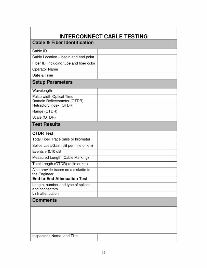
32
INTERCONNECT CABLE TESTING
Cable & Fiber Identification
Cable ID
Cable Location – begin and end point
Fiber ID, including tube and fiber color
Operator Name
Date & Time
Setup Parameters
Wavelength
Pulse width Optical Time Domain Reflectometer (OTDR)
Refractory index (OTDR)
Range (OTDR)
Scale (OTDR)
Test Results
OTDR Test
Total Fiber Trace (mile or kilometer)
Splice Loss/Gain (dB per mile or km)
Events > 0.10 dB
Measured Length (Cable Marking)
Total Length (OTDR) (mile or km)
Also provide traces on a diskette to the Engineer
End-to-End Attenuation Test
Length, number and type of splices and connectors
Link attenuation
Comments
Inspector’s Name, and Title

33
TABLE 647-8 LOOP INSTALLATION DATA SHEET
Conditions
Project Number:
Date:
Contractor:
Weather:
Temperature:
Pavement Condition – Wet ( ) or Dry ( )
Location
City or County: Phase:
Intersection Name or Number: Function:
Route Number(s) or Name(s): Lane Location:
Installation or Plan Sheet Number: No. of Turns:
Size and Type of Loop: Downstream/Upstream: Down ( ) Up ( )
Distance from Stop Bar: Distance E.O.P/Curb to Lead-in:
Distance Lead-in Cable:
Material
Loop Wire Color/Insulation Type/Gauge:
Loop Lead-In Wire Color/Insulation Type/Gauge:
Splice Point:
Conduit Length from Curb/E.O.P. to Splice Point:
Conduit Length from Splice Point to Cabinet:
Sealant Type and Part Number:
Sealant Manufacturer and Lot No.:
Interconnect Wire Type and Length:
Loop Tests
1. Induced Voltage
2. Inductance microhenries
3. Leakage Resistance to Ground megohms
4. Loop Resistance ohms
5. Loop Q (Quality) Q
Comments
Inspector’s Name, and Title

COBB COUNTY, GEORGIA
INTERSECTION LOG SHEET
Intersection of and .
DATE
INITIALS PROBLEM REPORTED/FOUND ACTION TAKEN
Time In Time
Out
Intersection # .

35
Revised for Cobb County April 27, 2017
Section 687 – Signal Timing
687.1 General Description
This work consists of providing, developing and implementing signal timing for an intersection in the adaptive traffic signal system SCATS, by a prequalified Contractor, a traffic signal operating plan designed to provide a safe and efficient operation of the Intersections included in this Special Provision. This work includes necessary controller and site license, system timing plan development, implementation and adjustment. 687.1.01 Deliverables The following items shall be included:
• Controller and Site License
• Update Intersection Graphics
• Provide the Current Software Version
• Develop Personality, Flexi-Link and Master-Link Signal Timing
• Implementation
• Provide Cabinet Graphic and Data-Key
687.2 Measurement
687.2.01 Construction Contracts Traffic signal timing as specified complete and accepted is measured for payment per Lump Sum.
687.3 Payment
687.3.01 Construction Contracts
Traffic signal timing complete and accepted is measured for payment per Lump Sum. Price and payment is full compensation for all materials, labor, tools, equipment, supplies, testing, and incidentals to complete the item of work
Payment will be made under:
Item No. 687 Traffic Signal Timing per Lump Sum

36
Revised for Cobb County May 9, 2013
Section 925 – Traffic Signal Equipment
925.1 General Description
This section provides specifications for a variety of traffic signal equipment.
925.1.01 Related References
A. Standard Specifications
Section 500 – Concrete Structures Section 639 – Strain Poles for Overhead Sign and Signal Assemblies Section 647 – Traffic Signal Installation Section 682 – Electrical Wire, Cable and Conduit Section 833 – Joint Fillers and Sealers Section 861 – Piling and Round Timber Section 870 – Paints (Field Painting) Section 915 – Mast Arm Assemblies Section 922 – Electrical Wire and Cable Section 923 – Electrical Conduit Section 926 – Wireless Communication Equipment Section 935 – Fiber Optic System Section 937 – Video Detection System Section 939 – Communications and Electronic Equipment
B. Referenced Documents
• National Electrical Manufacturers Association ( NEMA) Standards Publication TS 1 Section 15 \
• NEMA Standard Publication TS 2- 1998
• Institute of Transportation Engineers (ITE)Vehicle Traffic Control Signal Heads Specification
• ITE Vehicle Traffic Control Signal Heads: Light Emitting Diode (LED)Circular Signal Supplement June 27, 2005 Specification
• ITE Vehicle Traffic Control Signal Heads – Part 3: Light Emitting Diode (LED) Vehicle Arrow Traffic Signal Modules Specification
• ITE Pedestrian Traffic Control Signal indications – Part 2: Light Emitting Diode (LED) Pedestrian Traffic Signal Modules Specification
• International Municipal Signal Association (IMSA) #20-1 Specification
• IMSA #20-4Specification
• IMSA #20-6Specification
• IMSA #50-2Specification
• IMSA #51-1Specification
• Underwriters Laboratory Inc. (UL) 94 Tests for Flammability of Plastic Materials for Parts in Devices and Appliances
• UL 493 Standard for Safety for Thermoplastic-Insulated Underground Feeder and Branch-Circuit Cables
• Traffic Signal Control Equipment Specifications, January 1989 edition and applicable addenda, State of California Business, Transportation & Housing Agency
• State of California Department of Transportation (CALTRANS) Qualified Products List ( QPL) Controller Assemblies for the Model 170/2070 Traffic Controller,
• CALTRANS Transportation Electrical Equipment Specifications (TEES) August 16, 2002 and applicable addenda
• Georgia Department of Transportation Qualified Products List 75“Polyurethane Sealant for Inductive Loops”(American Society of Testing and Materials(ASTM) A36 Standard Specification for Carbon Structural Steel
• ASTM A53 Standard Specification for Pipe, Steel, Black and Hot Dipped, Zinc-Coated, Welded and Seamless
• ASTM A123 Standard Specification for Zinc (Hot-Dip Galvanized) Coating on Iron and Steel Products
• ASTM A153 Standard Specification for Zinc Coating (Hot Dip) on Iron and Steel Hardware
• ASTM A325 Standard Specification for Structural Bolts, Steel, Heat Treated, 120/105 ksi Minimum Tensile Strength
• ASTM A475 Standard Specification for Zinc-Coated Steel Wire Strand
• ASTM A572 Standard Specification for High- Strength Low-Alloy Columbium-Vanadium Structural Steel

37
• ASTM C1028 Standard Test Method for Determining the Static Coefficient of Friction of Ceramic Tile and Other Like Surfaces by the Horizontal Dynamometer Pull-Meter Method
• ASTM D256 Standard Test Methods for Determining the Izod Pendulum Impact Resistance of Plastics
• ASTM D638 Standard Test Methods for Tensile Properties of Plastics
• ASTM D785 Standard Test Method for Rockwell Hardness of Plastics: Electrical Insulating Materials
• ASTM D790 Standard Test Methods for Flexural Properties of Unreinforced and Reinforced Plastics and Electrical Insulating Materials
• ASTM D2444 Standard Test Methods for Determination of the Impact Resistance of Thermoplastic Pipe and Fittings by Means of a Tup
• ASTM D543 Standard Practices for Evaluating the Resistance of Plastics to Chemical Reagents
• Electronic Industries Standards (EIA)
• Georgia Department of Transportation (GDOT) Specifications
925.2 Materials
925.2.01 General
A. Requirements
Ensure that the traffic signal equipment and materials meet the Plans and Specifications.
All equipment furnished shall be new and meet the requirements of the following:
• Underwriter’s Laboratory Incorporated (UL)
• Electronic Industries Association (EIA)
• National Electric Code (NEC)
• American Society of Testing and Materials (ASTM)
• American National Standards Institute (ANSI)
• International Municipal Signal Association (IMSA)
• National Electrical Manufacturers Association (NEMA)
• Applicable Standards, Specifications, and Regulations of the: Georgia Department of Transportation Traffic Signal Electrical Facility & NaviGAtor Support (TSEF) 935 E. Confederate Avenue, Building 5 Atlanta, GA 30316
B. Fabrication
General Provisions 101 through 150.
C. Acceptance
General Provisions 101 through 150.
D. Materials Warranty
• Provide all manufacturers’ warranties and guarantees for all signal equipment items listed in this document as well as any signal equipment listed in the plans, except for state supplied equipment.
• Ensure that warranties and guarantees are consistent with those provided as customary trade practices; or as otherwise specified in the plans, Standard Specifications, Supplemental Specifications or Special Provisions.
• Ensure that manufacturer’s and supplier’s warranties and guarantees are transferable to the agency or user that is responsible for traffic signal maintenance, are continuous throughout their duration and state that they are subject to such transfer.
• Ensure equipment provided under this specification shall be warranted by the manufacturer to be free from defects in materials and workmanship for a period of two years from date of receipt or one year from date of acceptance of installation.
• Ensure the manufacturer will repair any faulty equipment during this period at no charge to the Department for parts, labor or shipping to and from the factory.
925.2.02 Type 2070 Controller Assemblies
A. Requirements
For 2070 controller cabinet assemblies, use 2070 controller units that meet the requirements of the following or are previously approved by TSEF:

38
• Traffic Electrical Equipment Specifications (TEES) published by the State of California Business, Transportation, and Housing Agency; Department of Transportation, current edition and current addenda
• CALTRANS Qualified Products List (QPL)
• GDOT Qualified Products List (QPL)
The following specifications augment the GDOT specifications and take precedence over conflicting GDOT specifications:
1. The unit shall be compatible with current GDOT licensed firmware. 2. The 2070 controller shall be compatible with the installation and operation of the current GDOT license intersection
software. 3. Each 2070 controller shall be shipped with one 5-volt 2 MB data key. 4. Each 2070 controller shall be compatible with the SCATS (Adaptive Signal Timing) software.
The following specifications augment the CALTRANS specifications and take precedence over conflicting CALTRANS Specifications.
1. Input/output (I/O) and Configuration:
The 2070 Controller shall be supplied in one of the following configurations, as specified in the Plans (all modules are specified in TEES, but these configurations supersede the defined configurations in TEES):
2070L: Provide Chassis, 2070-1C Single-Board CPU, 2070-2A Field I/O Module, 2070-3B Front Panel (8x40 display), 2070-4B 3.5-amp Power Supply, and a 2070-7A Module. This unit shall provide the default input and output configuration as shown in Tables 925 -6, 925-8 and 925-9 for ITS cabinets.
2070 LCN: Provide Chassis, 2070-1C Single-Board CPU, 2070-2B Field I/O Module, 2070-3B Front Panel (8x40 display), 2070-4NB 3.5-amp Power Supply, 2070-8 NEMA Interface Module, and a 2070-7A Module.
2. Power Supply Modules:
Either the 2070-4A, 2070-4B, 2070-4NA or 2070-4NB module shall be provided as required in the configuration requirements in the preceding Item. In addition to all requirements of the TEES, the power supplies shall be clearly marked as a “2070-4A”, “2070-4B”,”2070-4NA”, or “2070-4NB”. . The Vendor may supply a 2070-4A or 4NA power supply module in lieu of a 2070-4B or 4NB, as long as it is so marked and adds no additional cost to GDOT and/or Cobb DOT.
3. Documentation:
Include with each controller, manuals that document the programming, operation, and maintenance of the unit. Include schematic drawings and pin assignment charts in the manuals for maintenance. Documentation shall include all components, including communications modules.
4. Testing:
Provide for complete testing of unit before it is shipped. If unit is shipped with applications software installed. It must be tested with the application (e.g. Traffic Signal Control). If random samples of greater than 10 percent of the units tested are rejected then the total shipment shall be rejected and vendor will be responsible for all costs to test and repair all units provided.
B. Fabrication
General Provisions 101 through 150.
C. Acceptance
(See Subsection 925.2.02.A for compliance with CALTRANS QPL also see 4. Testing in Section A above.).
D. Materials Warranty:
(See Subsection 925.2.01.D for Materials Warranties).
925.2.03 Type 2070 Controller Subassemblies
A. Requirements
For 2070 controller cabinet subassemblies, use 2070 controller units that meet the requirements of the following or are previously approved by TSEF:
• Traffic Electrical Equipment Specifications (TEES) published by the State of California Business, Transportation, and Housing Agency; Department of Transportation, current edition and current addenda
• CALTRANS Qualified Products List (QPL)

39
The following specifications augment the CALTRANS specifications and take precedence over conflicting CALTRANS Specifications.
1. 2070 1C Module:
The 2070 1C module may be supplied as a separate item to be used in all versions of the 2070 controller. The 2070 1C module shall be supplied complete with the operating software. Ensure it contains the required files to be compatible with the current GDOT applications software.
2. 2070 2A Field I/O Module
The 2070 2A Field I/O module may be supplied as a separate item. The 2070 2A Field I/O module shall consist of the Field Controller Unit; Parallel Input/Output Ports; other Module Circuit Functions (includes muzzle jumper); Serial Communication Circuitry; Module Connectors C1S, C11S and C12S mounted on the module front plate; VDC Power Supply (+12VDC to + 5VDC) and required software. Ensure it contains any configuration jumpers to be compatible with current GDOT Applications software. Ensure the 2070 2A field I/O Module functions with a Model 2070 L or 2070LB Controller Assembly and is compatible with current GDOT applications software.
3. 2070 2B Field I/O Module:
The 2070 2B Field I/O module may be supplied as a separate item and consist of the Serial Communication Circuitry, DC power Supply, and Module Connector 12S mounted on the module front plate only. Ensure it contains any configuration jumpers to be compatible with current GDOT Applications software. Ensure the 2070 2B field I/O Module functions with a Model 2070 LC or 2070LCN1 Controller Assembly and is compatible with current GDOT applications software.
4. 2070 3B Front Panel Display Module:
The 2070 3B Display Module may be supplied as a separate item and provides a Front Panel Assembly controller, two keyboards, AUX switch alarm bell and an 8 line by 40 character display. This assembly shall also include a panel with latch assembly and two TSD #1 hinge attaching devices, assembly PCB, external serial port connectors, CPU active LED indicator, contrast adjustment knob, and Front Panel Harness. Ensure it contains any configuration jumpers to be compatible with current GDOT Applications software. Ensure the 2070 3B Front Panel Assembly Module functions with Models 2070 L, 2070 LC, 2070 LCN1 and 2070 LCN2 Controller Assemblies and is compatible with current GDOT applications software. Ensure the hardware hinge attaching devices mate with existing 2070 assemblies. Ensure the Front Panel Harness is connected to the front panel via a removable connector. Ensure the front panel connector supports the aux switch.
5. 2070 4B Power Supply Module:
The 2070 4B Power Supply Module may be supplied as a separate item and is an independent, self contained module. Ensure that it is vented and cooled by convection only. Provide module that slides into power supply compartment from the back of the chassis and is attached to the Backplane mounting surface by its four TSD #3 Devices. Ensure the module supplies at least 3.5 amperes of +5VDC. Ensure the 2070 4B Power Supply Module is compatible with Models 2070 L, 2070 LB, and 2070 LC Controller Assemblies and is compatible with current GDOT applications software. Ensure the connection harness PS 2 on existing units can be mated with the 4B module supplied. A 2070 4A Power Supply Module may be provided in place of a 4B module as long as it is labeled as such and there is no additional cost to GDOT. Ensure the module supplied is appropriately marked as a 4B or 4A module.
6. 2070 4NB Power Supply Module:
The 2070 4NB Power Supply Module may be supplied as a separate item and is an independent self contained module. Ensure that it is vented and cooled by convection only. Provide module that slides into power supply compartment from the back of the chassis and is attached to the Backplane mounting surface by its four TSD #3 Devices. Ensure the module supplies at least 3.5 amperes of +5VDC. Ensure the 2070 4B Power Supply Module is compatible with Models 2070 LCN1 and 2070 LCN2 Controller Assemblies and is compatible with current GDOT applications software. Ensure the connection harness PS 2 on existing units can be mated with the 4B module supplied. Ensure the 4NB power supply module supports the NEMA TS1 and TS2 Standards. A 2070 4A Power Supply Module may be provided in place of a 4B module as long as it is labeled as such and there is no additional cost to GDOT. Ensure the module supplied is appropriately marked as a 4NA or 4NB module.
7. 2070 7A Communications Module:
The 2070 7A Communications Module may be supplied as a separate item. The 7A communications module is a dual async serial communications module. Ensure the module supports serial communications on both ports. Ensure it contains any configuration jumpers to be compatible with current GDOT Applications software.

40
8. 2070 8 Field I/O Module:
The 2070 8 Field I/O Module may be supplied as a separate item. The 8 Field I/O Module consists of the module chassis, module power supply, Field Control Unit Controller, parallel input/output ports, serial communications circuits and module connectors. Ensure the EX1 connector is provided with appropriate mating connections to interface with either 6B or 7A communications modules. Ensure the 2070 8 Field I/O module is provided with the appropriate mating connector to mate with the C12S connector on the 2070 2B Field I/O module. Ensure the 2070 8 Field I/O module functions as part of a Model 2070 LCN1 controller.
B. Fabrication
General Provisions 101 through 150.
C. Acceptance
(See Subsection 925.2.02.A for compliance with CALTRANS QPL).
D. Materials Warranty:
(See Subsection 925.2.01.D for Materials Warranties).
925.2.04 Type 170E Cabinet Assemblies
A. Requirements
Ensure that the cabinet assembly meets the requirements of the GDOT and CALTRANS Specifications as described in this document.
In addition to the GDOT and CALTRANS Specifications, ensure that the cabinet assembly conforms to the requirements listed below, which take precedence over conflicting GDOT CALTRANS Specifications.
1. Cabinet configuration:
Supply cabinets in accordance with these specifications. Equip the cabinets with auxiliary equipment as follows:
a. Model 332 and 332A Cabinet:
Lower input field termination panel
1 – Model 242 DC Isolator in Slot 14 of Upper Input File
4 – Flash Transfer Relays
2 – Model 204 Flashers
1– Auxiliary Cabinet Shelf to support Communication Devices
1– 4 Position Power Strip
Note: Include above components in cabinet at time of delivery.
Other auxiliary cabinet components such as controllers, monitors, load switches, etc. will be ordered as separate items.
2. Finish
Use cabinets that have a bare aluminum finish and the internal racks shall have a galvanized finish to prevent rusting (see Subsection 925.2.06.A.1 for controller-cabinet minimum fabrication specifications).
3. Locks
Equip the main cabinet door with locks that accept No. 2 Corbin keys. Provide two sets of keys with each cabinet. One set of keys is defined as one – No. 2 key and one - police panel key.
4. Power
Equip the cabinet assemblies with a power distribution assembly to generate AC and DC power for the electronic components, except the DC power for the controller units. Provide the Model 332 and 332A cabinets with a 242 DC isolator for stop time/flash sense, located in slot 14 of the input file.
5. Mounting
N/A
6. Unused Phase Monitoring

41
Provide odd-phase reds with ballast resistor dummy loads. Do not wire the cabinet to monitor pedestrian yellow indications.
Neatly lace and bundle the wiring from the signal monitor for pedestrian yellow monitoring on the back panel.
7. Red Monitoring
Provide a connector and terminal assembly designated as P20 (Magnum P/N 722120 or equivalent) for monitoring the absence of red as an integral part of the output file.
Terminate the connector and ensure compatible with the cable and C connector of a Type 2010 conflict monitor unit capable of monitoring the absence of red.
Provide the pin assignments of the P20 connector and terminal assemble with the cabinet plans.
Ensure that the P20 connector is physically alike to the cable and connector of a Type 2010 conflict monitor unit to prevent the absence of red cable connector from being inserted into the P20 connector 180 degrees out of alignment.
Submit details for programming of the unused red channels for approval.
The Red Enable board shall be easily removable and replaceable from the outside of the Output File Assembly. Removal and replacement shall not require the Output File Assembly to be opened. The design shall be such that the board can be easily unplugged or replaced. During normal operation the board shall be secured to the Output File Assembly.
The Output File Assembly shall implement a hinged, clear, plastic cover to protect the Red Enable board during normal operation. This cover shall be hinged on the left or right side. When closed, the side opposite the hinge shall be secured to the Output File Assembly without the use of any hardware or tool. When fully opened, the cover shall not inhibit the removal, replacement or configuration of the Red Enable board. Removal/replacement of the Red Enable Board shall not require the removal of the protective cover.
Wiring in the Output File Assembly must be color coded so that individual wires correspond to their specific traffic signal outputs (EX: Red, Yellow, and Green). This will enhance the traceability of wires between termination points for technicians who are troubleshooting a cabinet while referencing the cabinet print.
8. Cabinet Light
Include in each cabinet one fluorescent lighting fixture mounted inside the top front portion of the cabinet.
The fixture includes a cool white lamp, covered, and operated by a normal power factor, UL listed ballast.
Install a door-actuated switch to turn on the cabinet light when either door is opened.
9. Cabinet Interlock
Do not install the interlock circuit, as detailed in the CALTRANS Specifications.
10. Cabinet Drawer
For all 332 Cabinet Assemblies, a hinged, aluminum shelf and integrated storage compartment shall be installed on the front door, inside the Cabinet Assembly. In order to allow better ventilation throughout the cabinet and rack, a sliding shelf/drawer within the rack assembly shall not be permitted. The shelf shall have a smooth, non-slip surface, sufficient for use as a writing platform and of sufficient size and rigidity to support a typical laptop computer when extended for use. This shelf shall have rounded or insulated edges that do not have the potential to physically harm the user. The shelf shall lock into place when folded for storage. Locking the shelf for storage and/or extending for use shall not require the use of any tool.
11. Auxiliary Equipment Shelf
Provide a “shelf” in each cabinet that provides a location to mount Fiber modem, dialup modem and/or Field hardened switch. Provide shelf in location that allows easy access to AC power outlets and communications links (telephone, interconnect). Locate shelf so as not block access to other equipment or modules including Battery Backup System.
12. Power Strip
Equip each cabinet with a power strip (minimum of 4 outlets) to support AC power for external communications devices in cabinet. Ensure that power strip may be used by block power supplies such that the block power supply does not block other outlets. Attach power strip to a permanent location that is easily accessible to devices in the rear of the cabinet. Do not plug power strip into GFI outlet.
13. Surge Protection

42
Equip each cabinet with EDCO surge protectors or approved equivalent to protect the control equipment from surges and over voltages.
Design the surge protector panels to allow for adequate space for a wire connection and surge protector replacement without the removal of terminal blocks or panels. Provide EDCO surge protectors or approved equivalent for the input sections as detailed below and as shown in the Input Terminal and Surge Arrestor Detail.
Supply EDCO surge protectors or approved equivalent that meet the following specifications.
a. AC Service Input
Each cabinet shall include a plug-able surge protection unit on the AC service input that meets or exceeds the following requirement: (EDCO SHA-1250 or equivalent utilizing 16 pin Beau connectors). The surge arrestor shall be a multi stage series hybrid type power line surge device. The surge arrestor shall be installed between the applied line voltage and earth ground. The unit shall have 2 LED indicators for operational display status. The surge arrestor shall be capable of reducing the effect of lightning transient voltages applied to the AC line and provide filtering that conforms to 50 kHz with a minimum insertion loss of 50db. The arrestor shall conform to the following:
• Peak surge current for an 8 X 20 microsecond waveform; 20,000 A for 20 occurrences.
• Clamp voltage at 20,000 A; 280 V max.
• Maximum continuous operating current at 120 V/60 Hz: 15 A
• Series Inductance: AC Line/AC Neutral 200 microhenries.
• Response time: (< a nanosecond) Voltage never exceeds 280V during surge.
• Temperature range: -40 to +85 degrees Celsius
• Spike suppression for +/- 700V spike: +/- 40 V deviations from sine wave all phase angles between 0 and 180 degrees.
The arrestor shall have the following terminals:
• Main Line (AC line first stage terminal)
• Main Neutral (AC neutral input terminal)
• Equipment Line In (AC line second stage input terminal, 10A)
• Equipment Line Out (AC line second stage output terminal, 10A)
• Equipment neutral out (neutral terminal to protected equipment)
• Ground (GND) (earth connection).
The arrestor shall be encapsulated in a flame-retardant material.
The equipment line out shall provide power to the Type 2070 controller and to the 24 V power supply.
The unit shall be a two-stage device that will allow the connection of the radio interference filter in the circuit between the stages.
AC Service Input suppressor shall be: EDCO # SHA-1250 or approved equivalent.
b. AC+ Interconnect Cable Inputs
Use a surge protection device to protect each AC interconnect line as it enters the cabinet with a surge protection device that meets or exceeds the following requirements:
• 3-electrode gas tube type of surge arrestor
• Striking voltage of 300-500 V DC with a minimum holder over voltage of 155V DC
• A three terminal device, one of which is connected to ground, the other two are connected across each input respectively
• The units must meet the following minimum requirements:
Impulse breakdown: Less than 100V in less than 1.1 s at 10 kV/s
Impulse breakdown balance: 0.01 microsecond (or less) difference at 10 kV/s impulse
Energy application: Withstands 20A AC for one (1) second applied ten (10) times at three (3) minute intervals on either section
Current rating: 10,000A (8 x 20 s impulse)
Capacitance: 6 pF, line to ground

43
c. Inductive Loop Detector Inputs
Type SC loop detector surge protectors shall be EDCO # SRA-6LC or approved equivalent
d. Low Voltage DC Inputs
Provide an external surge protection device for each low voltage DC input channel which meets or exceeds these requirements:
Surge current occurrences at:
2000 amperes, 8x20 microsecond waveform: at least 80
400 amperes, 10x700-microsecond waveform: at least 80
Peak surge current for: 10,000 amperes
8x20 microsecond waveform: (2,500 amperes/line)
100x 700-microsecond waveform: 500 amperes/line
Response time: < 1 nanosecond
Series resistance: 15 ohms, maximum
Capacity, average: 1500 picofarads
Temperature range: -40 oF (-40 oC) to +185 oF (85 oC)
Clamp Voltage: 30V line to line
This unit shall be a hybrid device with the first stage formed by a 3-element gas tube that will withstand a peak surge current (8x20 microsecond waveform) of 5000 amperes per side. The second stage shall dissipate at least 1.5 kilowatts.
No tools shall be required for the insertion and removal of the surge protector.
Type SC Communications Surge Protectors shall be EDCO # PC642C-030 or approved equivalent
Type SC communications surge protectors shall conform to all of the above requirements and shall service up to two communications circuit pairs. The Type SC surge protector shall have a printed circuit board card-edge connector that will mate with a Buchannan PN PCB 1B-10A connector. The contact strips shall be gold-plated. The Type SC surge protector shall be furnished with a mating socket. The maximum size of the Type SC surge protector with its socket shall be 2”x2.75”x 1.25”.
e. Coaxial Video Cables
This unit shall be a hybrid device, with the first stage formed by a gas tube that will withstand a peak surge current (8x20 microsecond waveform) of 5000 amperes. The second stage shall dissipate at least 1.5 kilowatts. EDCO # CX06-M and CX06-MI or approved equivalent
Peak Surge Current
8x20us 10K (2500A per line)
10x700us 500A per line
Technology Hybrid, Solid State
Attenuation 0.1db @ 10 MHz
Response Time <1 nanosecond
Protection Signal to ground
Clamp Voltage 6 volts
Connectors BNC, F, UHF
Impedance 50 or 75 ohms
Temperature -40 to 85+ C
Humidity 0-95% non-condensing
f. High Frequency Coax Protector

44
The surge protector shall protect sensitive electronic equipment from damage due to excessive voltage or currents generated by lighting or static build-up. There shall be a replaceable protection cartridge and a low signal loss at frequencies up to 3 gigahertz. It should accommodate both bulkhead mount and stud mount. The Input and Output connections shall be interchangeable.
General Requirements:
Frequency 0 to 4000 MHz
Max Insertion Loss 0.3 dB
Max VSWR 1.2
Characteristic Impedance 50 Ohms
DC Blocking None
Connectors Female N-Type
Breakdown Voltage 350 V
Surge Current 5000 Amps
Cartridge Life >600 Times @ 500 Amp pulse
Size 1 x 1.25 x .875 (W x H x L)
Mounting Stud ¼ x 20
High frequency coax protector shall be EDCO # CX-HFN or approved equivalent.
g. Surge Protection for Computers or Peripherals
The surge protector should utilize silicon avalanche clamp devices. It should be able plug in series with the data cable at or near the equipment to be protected.
General Requirements:
Max Operating Voltage (10 x 1000us) + 20V
Leakage Current (typical) 5uA
Max Data Rate 150 kb
Operating Temperature 0 C to +85 C
Max Surge Current (10 x 1000us) 43A
Max Clamp Voltage 35V
Clamp Response Time <1ns
Suppressor shall be EDCO # SRS-232 Series or approved equivalent.
h. Internal Mount 120VAC Surge Protection
The unit shall be an advanced 3 stage hybrid, solid state power line protector, The unit shall have features such as noise filtering, common mode and normal mode suppression, nanosecond reaction time, power line tracking, and compression screw terminations. The unit shall have a replaceable fuse designed to remove the load from the line if the unit is either overloaded or the internal protection fails.
General Requirements:
Clamping Cat. 330V L-N, 400V L-G ANSI/IEEE C62.41 1991-Cat. C1/B3
Peak Clamp Voltage 315V L-N, 350V L-G
Peak Surge Current (8 x 20us) 10kA Min.
Peak Surge Energy (10 x 1000us) 100A Min.
Response Time <5 nanoseconds
Operational Temperature -20 C to +85 C
Failure Indication LED
Operational Voltage 120V AC, 60 Hz

45
Operational Current 15 Amps Service
Dimensions (H x W x L) 1.825” x 2.95” x 5.25”
Suppressor shall be EDCO # HSP121BT-1RU or approved equivalent.
i. Internal Mount Ethernet Surge Protection
The surge protector shall provide lightning and surge protection for up to four Ethernet lines using 10/100/1000 data rates. The unit shall be rack mountable and compatible with 802.3af/at power-over-Ethernet (PoE) devices.
General Requirements:
Clamping Voltage Line-Ground: 65 Volts, Line-Line: 65 Volts
Ethernet Connectors 4 circuits of (2) RJ-45 Jack Pairs
Data Line Impedance 100 Ohms Balanced
Operational Temperature -40 C to +80 C
Dimensions (H x W x D) 3” x 19” x 2”
14. Suppressor shall be L-Com # RMSP-CAT-6-4 or approved equivalentType 2010 Signal Monitors
a. Introduction
This Specification sets forth the minimum requirements for a rack-mountable, sixteen channel, solid-state 2010 Signal Monitor for a Type 170E Traffic Cabinet Assembly. Ensure that as a minimum, the Signal Monitor complies with all Specifications outlined in Chapter 3 Section 6 of the California TEES, August 2002. Where differences occur, this Specification governs. Ensure that the manufacturer of the unit is listed on the current California Department of Transportation (Caltrans) Qualified Products List (QPL) for signal monitors.
Provide a Signal Monitor that is capable of monitoring sixteen channels consisting of a Green input, a Yellow input, and a Red input for each channel. Ensure that the unit also includes the enhanced monitoring functions described in Subsection 925.2.03.A.14.b, diagnostic display functions described in Subsection 925.2.03.A.14.c, event logging functions described in Subsection 925.2.03.A.14.d, communications functions described in Subsection 925.2.03.A.14.e, and hardware functions described in Subsection 925.2.03.A.14.f.
b. Monitor Functions
Except for Conflict faults, compute all fault timing for each channel individually.
1) Conflict Monitoring
Ensure that the Signal Monitor is able to detect the presence of conflicting green or yellow signal voltages on the AC field terminals between two or more non-compatible channels. A Conflict fault (CONFLICT) shall be a latching fault.
2) Conflict Recognition Time
Ensure the Signal Monitor shall trigger when voltages on any conflicting channels are present for more than 500 ms. Ensure that the Signal Monitor does not trigger when voltages on any conflicting channels are present for less than 200 ms. Conflicting signals sensed for more than 200 ms and less than 500 ms may or may not trigger the unit.
3) 24VDC Monitoring VDC
Ensure that the Signal Monitor is able to detect that the cabinet +24 Vdc supply has fallen below 18 Vdc. A 24VDC failure (VDC FAIL) shall be a latching fault.
4) 24VDC Recognition Time
Ensure that the Signal Monitor shall trigger when the voltage on the +24V input is below 18 Vdc for more than 500 ms. Ensure that the Signal Monitor does not trigger when the voltage on the +24V input is below 18 Vdc for less than 200 ms. A voltage level of +22 Vdc will be required to prevent the unit from triggering.
5) Controller Watchdog Monitoring
Ensure that the Signal Monitor triggers when the Watchdog input does not toggle within the programmed time period (WDT ERROR). Ensure that the unit remains latched in the fault state until reset by the Reset button, an External Reset input command, or AC Line voltage restoring from a AC Line Brownout event

46
(see 2.4). Ensure that a reset resulting from an AC Line Brownout event does not clear the WDT ERROR LED.
6) Controller Watchdog Latch Option
Ensure a programming option sets the Watchdog monitoring function to a latching mode and that only a reset from the Reset button or External Reset input can clear a Watchdog fault. An AC Line brownout condition will not reset the fault.
7) Controller Watchdog Recognition Time
Ensure a programming option sets the maximum Watchdog recognition time to: 1000 + or - 100 ms; or 1500 + or - 100 ms.
8) Controller Watchdog Enable Switch
Provide an internal switch to disable the Watchdog monitoring function. Mount the switch on the PCB and be clearly label "WD ENABLE - ON...OFF". Ensure that placement of the switch in the OFF position causes monitoring of the Watchdog to be inhibited.
9) WDT ERROR LED Control
Ensure that the WDT ERROR LED illuminates when the unit has been triggered by a Watchdog fault. Ensure that it can only be cleared by a reset command from the front panel Reset switch or External Reset input. If the Watchdog monitoring function is inhibited due to the Watchdog Enable switch, the WDT ERROR LED shall flash at a 0.5 Hz rate.
10) AC Line Monitoring
a) AC Line Brownout Recognition
Ensure that the Signal Monitor is able to detect that the AC Line has fallen below 98 + or - 2 Vac for greater than 400 + or - 50 ms. This shall force the output Relay to the de-energized "fault" state, enable the Stop-Time output, and cause the AC POWER LED to flash at a 2 Hz rate. Ensure that the unit maintains this state until the AC Line voltage rises above 103 + or - 2 Vac for greater than 400 50 ms. Provide a jumper option which will change the AC Brownout dropout level to 92 + or - 2 Vac and the restore level to 98 + or - 2 Vac.
b) AC Line Power-up and Brownout Delay Time
When the AC Line is greater than 103 + or - 2 volts after power-up or Brownout restore, ensure that the Signal Monitor holds the Output Relay in the de-energized "fault" state and enable the Stop-Time output, for a period of not less than 6.0 + or - 0.5 seconds and not greater than 10.0 + or - 0.5 seconds. Ensure that this flash interval is terminated after at least 6.0 + or - 0.5 seconds if the Signal Monitor has detected at least five transitions of the Watchdog input. If the Signal Monitor does not detect five transitions of the Watchdog input before 10.0 + or - 0.5 seconds, ensure that the Signal Monitor goes to the fault state. During this interval, ensure that the AC POWER LED flashes at a 4 Hz rate.
c) Red Fail Monitoring
Ensure that the Signal Monitor is able to detect the absence of an active voltage on the green and yellow and red field signal inputs of a channel. Red Fail fault (RED FAIL) shall be a latching fault. Ensure that the Red Fail monitoring function is enabled for all channels except when the Red Enable input is not active, or pin #EE is active, or Special Function #1 input is active, or Special Function #2 input is active.
d) Red Fail Recognition Time
Ensure the Signal Monitor triggers when an active voltage on one of the three inputs of a channel are absent for more than 1500 ms. Ensure that the Signal Monitor does not trigger when an active voltage on one of the three inputs of a channel are absent for less than 1200 ms. Channels without proper voltages sensed for more than 1200 ms and less than 1500 ms may or may not trigger the unit. Provide an option switch (RF 2010) which will change the fault recognition time to between 700 ms and 1000 ms.
e) Red Interface Cable Fault
Ensure a programming option is provided such that operating without the Red Interface cable installed shall cause the Signal Monitor to enter the fault mode causing the Output relay contacts to close and

47
enabling the Stop-Time output to the controller. To indicate this fault mode, ensure that the Red Fail indicator is illuminated with all fault channel indicators Off.
Ensure that any Red Fail preemption control to the monitor uses the Special Function inputs #1 or #2.
f) Dual Indication Monitoring
Ensure that the Signal Monitor is able to detect the presence of active voltage on the green and yellow, green and red, or yellow and red field signal inputs of a channel. GYR Dual Indication fault (DUAL IND) shall be a latching fault. Ensure this function is enabled on a per channel basis using dip switches mounted on the PCB labeled "CH1" through "CH16". Ensure that the GYR Dual Indication monitoring function is enabled for all selected channels except when the Red Enable input is not active or pin #EE is active.
g) GY Dual Indication Monitoring
Ensure that the Signal Monitor is able to detect the presence of active voltage on the green and yellow field signal inputs of a channel. GY Dual Indication fault (DUAL IND) shall be a latching fault. Enable this function with a dip switch on the PCB labeled "GY ENABLE". When the switch is in the ON position, monitor all channels for simultaneous active green and yellow inputs on a channel. When selected by the GY ENABLE switch, ensure that the GY Dual Indication monitoring function is disabled when pin #EE is active.
h) Dual Indication Recognition Time
Ensure that the Signal Monitor triggers when multiple inputs are active on a channel for more than 500 ms. Ensure that the Signal Monitor does not trigger when multiple inputs are active on a channel for less than 250 ms. Channels with multiple voltages active for more than 250 ms and less than 500 ms may or may not trigger the unit.
i) Sequence (Short or Absent Yellow) Monitoring
Ensure that the Signal Monitor is able to detect that a channel has not provided an adequate Yellow Clearance interval during a green to yellow to red sequence. A Sequence failure (SEQUENCE) shall be a latching fault. Ensure that this function is enabled on a per channel basis using dip switches mounted on the PCB labeled "CH1" through "CH16". Ensure that the Sequence monitoring function is enabled for all selected channels except when the Red Enable input is not active or pin #EE is active.
j) Sequence Recognition Time
The minimum Yellow Clearance interval may be modified by switches mounted on the PCB labeled "YEL TIME 1", "YEL TIME 2", and "YEL TIME 3". Ensure that the Yellow Clearance interval is 2.7 seconds plus 0.2 seconds times the binary sum of the three switches. The minimum Yellow Clearance interval shall therefore have a range of 2.7 seconds to 4.1 seconds, 0.1 seconds.
k) Recurrent Pulse Detection (RP Detect)
Ensure that the Signal Monitor detects Conflict, Red Fail, and Dual Indication faults that result from intermittent or flickering field signal inputs. These recurring pulses shall result in a latching fault with the RP DETECT indicator illuminated along with the resulting Conflict, Red Fail, or Dual Indication indicator. Provide an option switch to disable the RP detect function.
l) Configuration Change Monitoring
On power-up, reset, and periodically during operation, ensure that the Signal Monitor compares the current configuration settings with the previously stored value and if the settings have changed, the Signal Monitor automatically logs the new setting. Ensure that these settings include the permissive diode matrix, all switches, all jumpers, and the Watchdog Enable switch.
Provide a programming option such that any change in the configuration parameters will cause the Signal Monitor to enter the fault mode causing the Output relay contacts to close and enabling the Stop-Time output to the controller. To indicate this fault mode ensure that the PCA indicator will flash at a 4 Hz rate. Depressing the Reset button for 5 full seconds is required to clear this fault and log the new configuration parameters.
If the programming option is not selected, ensure that the unit does not set the fault mode but will still log the configuration change.
m) Program Card Ajar

48
Ensure that when the Programming Card is removed or not seated properly, the Signal Monitor forces the Output Relay to the de-energized "fault" state, enable the Stop-Time output, and illuminate the PCA LED. A reset command from the front panel Reset switch or External Reset input is required once the Program Card is in place.
n) Exit Flash
When the Signal Monitor exits the flash state (Output relay de-energized) as a result of a Reset command or AC Line brownout restore, ensure that the Stop Time output goes to the inactive state 250 + OR - 50 ms before the Output relay transfers to the energized state. This transition will provide an early indication to the Controller Unit that the cabinet will transfer from flash to signal operation.
c. Display Functions
Ensure that it is possible to view the active channels for each individual color (GYR) during operation and when latched in a fault state. When the Signal Monitor is latched in a fault state ensure that it is also be possible to view the active channels for each individual color and fault status for each channel for the current fault and the two previous faults.
1) Previous Fault GYR Display
When the Signal Monitor has been triggered by a fault the channel status display will alternate between the channels which were involved in the fault (fault status) for 2 seconds, and the field signals active at the time of the fault for 6 seconds. The channels involved in the fault will flash their respective Green, Yellow, and Red indicators simultaneously at a 4 Hz rate for the 2 second interval.
The two previous faults may also be displayed individually. This status is not reset by an AC Line power interruption. To enter this display mode remove the Program Card. The sequence is as follows:
Reset Event PCA LED Fault Status LEDs Channel Status LEDs
--- #1 Single flash Current Fault Status (newest) Current Field status
#1 #2 Double flash Event #2 Fault Status Event #2 Field status
#2 #3 Triple flash Event #3 Fault Status (oldest) Event #3 Field status
(repeats back to top)
d. Event Logging Functions
Ensure that the Signal Monitor is capable of storing in non-volatile memory a minimum of 100 events. Mark each event with the time and date of the event. These events consist of fault events, AC Line events, reset events, and configuration change events. Provide a graphical means of displaying the signal states of all field inputs for 30 seconds prior to a fault trigger event. Provide the capability to assign a four-digit identification number to the unit shall be provided. Upload the event logs to a PC using the serial port of the Signal Monitor and software provided by the manufacturer.
Ensure each event log report contains the following information:
• Monitor ID#: a four digit (0000-9999) ID number assigned to the monitor.
• Time and Date: time and date of occurrence.
• Event Number: identifies the record number in the log. Event #1 is the most recent event.
1) Monitor Status Report (CS)
Ensure the Current Status report contains the following information:
a) Fault Type: the fault type description.
b) Field Status: the current GYR field status and field RMS voltages if the monitor is not in the fault state, or the latched field status and field RMS voltages and fault channel status at the time of the fault.
c) Cabinet Temperature: the current temperature if the monitor is not in the fault state, or the latched temperature at the time of the fault.
d) AC Line Voltage: the current AC Line voltage if the monitor is not in the fault state, or the AC Line voltage at the time of the fault.

49
e) Control Input Status: the current state and RMS voltages of the Red Enable input, EE input, and Special Function #1 and #2 inputs if the monitor is not in the fault state, or the status latched at the time of the fault.
2) Previous Fault Log (PF)
Ensure the Previous Fault log contains the following information:
a) Fault Type: the fault type description.
b) Field Status: the latched field status with RMS voltages, and fault channel status at the time of the fault.
c) Cabinet Temperature: the latched temperature at the time of the fault.
d) AC Line Voltage: the AC Line voltage at the time of the fault.
e) Control Input Status: the latched state of the Red Enable input, EE input, and Special Function #1 and #2 inputs at the time of the fault.
3) AC Line Event Log (AC)
The AC Line log shall contain the following information:
a) Event Type: describes the type of AC Line event that occurred.
Power-up—AC on, monitor performed a cold start
Interrupt—AC Line < Brownout level
Restore—AC restored from brown-out or interruption (AC Off), no cold start
b) AC Line Voltage: the AC Line voltage at the time of the event.
4) Monitor Reset Log (MR)
Ensure the Monitor Reset log contains the following information:
a) The monitor was reset from a fault by the front panel Reset button or External Reset input.
5) Configuration Change Log (CF)
Ensure the Configuration Change log contains the following information:
a) Program Card Matrix: the permissive programming for each channel.
b) Yellow Disable Jumpers: the Yellow Disable programming for each channel.
c) Dual/Sequence Switches: the switch programming for each channel.
d) Option Switches: RF 2010, RP Disable, GY Enable, SF1 Polarity, Sequence Timing, Minimum Flash Enable, Configuration Fault Enable, Red Cable Fault enable, AC Brownout timing.
e) Watchdog Programming: Watchdog Enable, Watchdog Latch, and Watchdog timing.
f) Configuration CRC: A unique CRC value which is based on the configuration of items #a though #e above.
Indicate on the log, which items have been changed since the last log entry.
6) Signal Sequence Log
Provide a log that graphically displays all field signal states for up to 30 seconds prior to the current fault trigger event. Ensure that the resolution of the display is at least 50 milliseconds.
e. Communication Functions
1) Controller Unit Communications
Ensure that the Signal Monitor is compatible with the Command/Response protocol of BI Tran Systems Inc. Model 233 Software. Ensure the unit supports command types 02 and 07.
2) Personal Computer Communications
Have the manufacturer provide software to access the Signal Monitor status and event logs described in Subsection 925.2.01.A.14.d. Ensure this software operates with Microsoft Windows 2000TM or Windows XPTM

50
f. Hardware
1) Red Monitoring
a) Red Field Inputs
Ensure that the Signal Monitor is capable of monitoring sixteen Red field signals. Ensure that a Red input is sensed active when the input voltage exceeds 70 Vrms. Ensure that a Red input is sensed not active when the input voltage is less than 50 Vrms. A Red input may or may not be sensed active when the input voltage is between 50 Vrms and 70 Vrms.
b) Red Enable Input
Ensure that the Red Enable input provides an AC input to the unit which enables Red Monitoring, Dual Indication Monitoring, and Sequence monitoring when the input is sensed active.
Ensure that the Red Enable input is sensed active when the input voltage exceeds 70 Vrms. Ensure that the Red Enable input is sensed not active when the input voltage is less than 50 Vrms. The Red Enable input may or may not be sensed active when the input voltage is between 50 Vrms and 70 Vrms.
c) Special Function Preemption Inputs
Ensure that the Special Function Preemption inputs #1 and #2 provide an AC input to the unit which disables only Red Fail Monitoring (Lack of Output) when either input is sensed active.
Ensure that a Special Function input is sensed active when the input voltage exceeds 70 Vrms. Ensure that a Special Function input is sensed not active when the input voltage is less than 50 Vrms. A Special Function input may or may not be sensed active when the input voltage is between 50 Vrms and 70 Vrms.
Use a PCB mounted switch to provide the option to invert the active status of the Special Function #1 input. When the switch is in the ON position, ensure that the Special Function #1 input is sensed not active when the input voltage exceeds 70 Vrms. Ensure that the Special Function #1 input is sensed active when the input voltage is less than 50 Vrms. The Special Function #1 input may or may not be sensed active when the input voltage is between 50 Vrms and 70 Vrms.
d) Red Interface Connector
This connector provides the required inputs for the unit to monitor the Red field signal outputs. Ensure the connector is a 3M #3428-5302 type or equivalent and be polarized to insure proper mating with the cable. Ensure Ejector latches are included to facilitate removal and prevent the cable from inadvertently disconnecting. Ensure the unit shall function as a standard 210 Signal Monitor when the cable is disconnected. Use the pin assignments shown in Table 1.
Table 1
Pin Function Pin Function
1 Channel 15 Red 11 Channel 9 Red
2 Channel 16 Red 12 Channel 8 Red
3 Channel14 Red 13 Channel 7 Red
4 Chassis Ground* 14 Channel 6 Red
5 Channel 13 Red 15 Channel 5 Red
6 Special Function #2 16 Channel 4 Red
7 Channel 12 Red 17 Channel 3 Red
8 Special Function #1 18 Channel 2 Red
9 Channel 10 Red 19 Channel 1 Red
10 Channel 11 Red 20 Red Enable
*A jumper option shall be provided to allow the connection of Pin #4 to be made with Chassis Ground.

51
2) Front Panel
Ensure the front panel is constructed of sheet aluminum with a minimum thickness of 0.090 in. (2.286 mm), and finished with an anodized coating. Ensure the model information shall be permanently displayed on the front surface.
a) Indicators
Ensure that all display indicators are mounted on the front panel of the Signal Monitor and are water clear, T-1 package, Super Bright type LEDs. Ensure that all fault LEDs are red except the AC POWER indicator which is green. Provide a separate Red, Yellow, and Green indicator for each channel. Label the indicators and provide the information as follows:
1) AC POWER
Ensure the AC Power indicator flashes at a rate of 2 Hz when the unit has detected a low voltage condition as described in Subsection 925.2.03.A.14.b.10).a. Ensure the AC POWER indicator flashes at a rate of 4 Hz during the minimum flash interval as described in Subsection 925.2.03.A.14.b.10).b. Ensure that the indicator illuminates when the AC Line voltage level is restored above the brownout level. Ensure the indicator extinguishes when the AC Line voltage is less than 80 Vac.
2) VDC FAILED
Ensure the VDC FAILED indicator illuminates when a 24VDC fault condition is detected. This indicator remains extinguished if the monitor has not been triggered by a 24VDC fault.
3) WDT ERROR
Ensure the WDT ERROR indicator illuminates when a controller Watchdog fault is detected. Ensure the WDT Error indicator flashes ON once every 2 seconds if the WD Enable switch on the monitor is placed in the OFF position to disable Watchdog monitoring, or the AC Line voltage is below the Watchdog disable level.
4) CONFLICT
Ensure that the CONFLICT indicator illuminates when a conflicting signal fault is detected.
5) DIAGNOSTIC
Ensure the DIAGNOSTIC indicator illuminates when one of the following faults are detected: Internal Watchdog fault, Memory Test fault, or Internal power supply fault. This indicator is intended to inform the service technician of a monitor hardware or firmware failure.
6) RED FAIL
Ensure the RED FAIL indicator illuminates when an absence of signal is detected on a channel(s). Ensure the RED FAIL indicator flashes ON once every two seconds if the RED ENABLE input is not active, or a Special Function input is active, or the EE input is active
7) DUAL IND.
Ensure the Dual IND. indicator illuminates when a GY-Dual or GYR-Dual Indication fault is detected on a channel(s).
8) SEQUENCE
Ensure the Sequence indicator illuminates when the minimum Yellow Clearance time has not been met on a channel(s).
9) PCA
Ensure the PCA indicator illuminates if the Program Card is absent or not properly seated.
If the unit is in the Diagnostic Display mode, ensure the PCA indicator flashes ON (once, twice, or three times) to indicate the fault event number being displayed. See Subsection 925.2.03.A.14.c.
10) RP DETECT
Ensure the RP DETECT indicator illuminates when the unit has detected a Conflict, Red Fail, or Dual Indication fault as a result of recurring pulse field inputs.

52
11) CHANNEL STATUS
Ensure that during normal operation the 48 Channel Status indicators displays all active signals (Red, Green, and Yellow).
In the fault mode, ensure that the Channel Status indicators display all signals active at the time of the fault for six seconds and then indicate the channels involved in the fault for 2 seconds.
b) Front Panel Control
1) RESET Button
Provide a momentary SPST Control switch labeled RESET on the unit front panel to reset the monitor circuitry to a non-failed state. Position the switch on the front panel such that the switch can be operated while gripping the front panel handle. Ensure that a reset command issued from either the front panel button or External Reset input is a one-time reset input to prevent the unit from constant reset due to a switch failure or constant external input, and causes all LED indicators to illuminate for 300 ms.
The Reset button also provides control of the Diagnostic Display mode. For a complete description of Diagnostic Display operation, see Subsection 925.2.03.A.14.c.
c) Serial Communications Connector Use this connector to provide EIA-232 serial communications. Ensure that it is an AMP 9721A or equivalent 9 pin metal shell D subminiature type with female contacts. Refer to Table 2 for Pin assignments.
Table 2
Pin Function
1 DCD*
2 TX DATA
3 RX DATA
4 DTR (Data Terminal Ready)
5 SIGNAL GROUND
6 DSR
7 DSR*
8 CTS*
9 NC
* Provide Jumper options to allow the connection of Pin #4 to be made with Pin #7, and the connection of Pin #8 to be made with Pin #1.
3) Electronics
a) RMS Voltage Sampling
Use high speed sampling techniques to determine the true RMS value of the AC field inputs. Sample each AC input at least 32 times per cycle. Ensure that the RMS voltage measurement is insensitive to phase, frequency, and waveform distortion.
b) Internal MPU Watchdog
Use a microprocessor for all timing and control functions. Verify continuing operation of the microprocessor by an independent monitor circuit, that forces the Output Relay to the de-energized "fault" state, enable the Stop-Time output, and illuminate the DIAGNOSTIC indicator if a pulse is not received from the microprocessor within 300 ms.
If the microprocessor should resume operation, ensure the Signal Monitor continues to operate. Ensure that this monitoring circuit is also configurable to latch in the fault state. Ensure the unit requires a power-up cycle to reset the circuit once it is triggered.

53
c) Sockets
In the interest of reliability, ensure that only the PROM memory device for the microprocessor firmware is socket mounted. Ensure that the PROM memory socket is a precision screw machine type socket with a gold contact finish providing a reliable gas tight seal. Low insertion force sockets or sockets with "wiper" type contacts are not acceptable.
d) Internal Power Supply
Use a built-in, high-efficiency switching power supply to generate all required internal voltages. Ensure that all supply voltages regulated. Failure of the internal power supply to provide proper operating voltages shall force the output Relay to the de-energized "fault" state, enable the Stop-Time output, and illuminate the DIAGNOSTIC indicator. Provide a user replaceable slow blow fuse for the AC Line input. Ensure the unit is operational over the AC Line voltage range of 75 Vac to 135 Vac.
e) Ethernet Interface
Ensure the 10/100Mbps Ethernet port provides access by a local PC or remote TMC running ECcom Windows based software for status event log review, and archival.
f) Configuration Parameters
Select user-programmed configuration settings using PCB mounted switches or jumpers. Designs requiring a Personal Computer (PC) to program or verify the configuration parameters are not acceptable. Ensure that user-programmed configuration settings that are transferred to memory are stored in a programmable read-only memory (PROM or EEPROM). Designs using a battery to maintain configuration data are not acceptable.
g) Field Terminal Inputs
Ensure that all 120 Vac field terminal inputs provide an input impedance of 150K 50K ohms and be terminated with a discrete resistor having a power dissipation rating of 0.5 Watts or greater and a voltage rating exceeding 350 volts.
h) Component Specifications
Ensure that all electrical components used in the Signal Monitor are rated by the component manufacturer to operate beyond the full unit operating temperature range of –29 oF to 165 oF(-34 oC to +74 oC).
i) Printed Circuit Boards
Ensure that all printed circuit boards meet the requirements of the California Traffic Signal
Control Equipment Specifications, January 1989, plus the following requirements to enhance reliability:
1. All plated-through holes and exposed circuit traces are plated with solder.
2. Both sides of the printed circuit board are covered with a solder mask material.
3. The circuit reference designation for all components and the polarity of all capacitors and diodes are clearly marked adjacent to the component. Ensure that Pin #1 for all integrated circuit packages is designated on both sides of all printed circuit boards.
4. All electrical mating surfaces are gold plated.
5. All printed circuit board assemblies are coated on both sides with a clear moisture-proof and fungus-proof sealant.
6. All components and wire harnesses are mounted to the PCB using plated holes. "Piggy back" connections or jumper wires are not acceptable.
7. Conflict monitor shall be EDI 2010ECLip or approved equivalent
15. Model 208 Monitor Unit – Removed
16. Model 242 DC Isolator
Provide Model 242 DC Isolators that are in accordance with the latest version of CALTRANS Specifications. Ensure that the 242 isolator input signal polarity may easily be inverted without the use of tools. Provide isolators that:

54
• Output is OFF for input voltages greater than 12 volts;
• Output is ON for voltages of less than 8 volts that have a duration of at least 5 to 25 ms (optional 2-7 ms);
• Minimum output pulse width is 100 ms with a valid input (can be disabled);
• Output is optically isolated open collector NPN transistor;
• Capable of sinking 50 ma when on;
• Can register a new input within 25 ms of the old signal going away; and
• Output clamped on power up and down
• Compatible with 2070 controllers and latest version of Caltrans TEES including errata
17. Model 200 Switchpack
Provide Model 200 Switchpacks that are in accordance with the latest version of CALTRANS Specifications as referenced earlier in this section.
18. Model 204 Flasher Unit
Provide Model 204 Flasher Units that are in accordance with the latest version of CALTRANS Specifications as referenced earlier in this section.
19. Flash Transfer Relay
Provide Flash Transfer Relays that are in accordance with the latest version of CALTRANS Specifications as referenced earlier in this section.
20. Cabinet Model 332A
Provide Cabinet Model 332 that meets the CALTRANS Specification with the addition of surge protection as detailed in Table 925-1 Model 332A Default Input Files Assignment Detail and Table 925-2 Required Surge Arrestors for Model 332A Cabinet.
Supply Model 332 (lower input panel) cabinets, with housing Type 1B, and all components as described in these specifications.
Supply cabinets having two input files which conform to the CALTRANS Specifications and configured to accept two 2070 controllers in the top portion of the cabinet.
Configure the cabinet for dial up communications. Mount a two (2) circuit Buchanan connector on the right side panel (from rear door).
Mount a phone jack with a RJ11 connector above or to the right of the Buchanan terminal block.
Wire the phone jack to the Buchanan and to the Terminal Block (TB0) in accordance with Figure 925-1.
A manual jack shall be installed on the police panel. The jack shall inter-mate with a three circuit 1/4 inch (6.35 mm) diameter phone plug. The tip and ring (middle) circuits of the jack shall-be connected to the logic ground and the interval advance inputs of controller unit. When the manual hand cord is plugged into the jack and the pushbutton is pressed, logic ground shall be connected to the interval advance input of the controller unit.
A manual pushbutton with cord shall be provided. The cord shall have a minimum length of 3 feet (0.9 m). It shall have a 1/4 inch (6.35 mm) diameter, three circuit plug connected to one end and a manual pushbutton enclosed in a hand held enclosure at the other end. A complete cycle (push-release) of the manual pushbutton shall terminate the controller unit interval which is active except the vehicular yellow and all red clearance intervals. Cycling the push-button during the vehicular yellow or all red clearance intervals shall not terminate the timing of those intervals.
Supply cabinets with a 12” x 16” x 1” Air Filter
21. Cabinet Model 332A with Auxiliary Output File
Ensure that this unit meets the requirements of Subsection 925.2.03.A.20 above, except that the cabinet is configured with an Auxiliary Output File. Additionally, the field wiring terminals may be mounted on the rear of the input file.
22. Cabinet Model 336S (Base Mount)
This unit meets the CALTRANS Specification with the addition of approximately 6 additional inches (150 mm) of cabinet height exclusive of the "M" base adapter. Configure the internal component layout so that the additional space is available in the bottom area of the cabinet cage. Ensure that the field wiring input panels and surge protection conform to Table 925-6 Model 336S Default Input File Assignment Detail and Table 925-7 Required Surge Arrestors for Model 336S Cabinet.

55
Ensure that the C1 connector harness is provided with pins for all 104 inputs and outputs from the controller.
A manual jack shall be installed on the police panel. The jack shall intermate with a three circuit 1/4 inch (6.35 mm) diameter phone plug. The tip and ring (middle) circuits of the jack shall-be connected to the logic ground and the interval advance inputs of controller unit. When the manual hand cord is plugged into the jack and the pushbutton is pressed, logic ground shall be connected to the interval advance input of the controller unit.
A Manual ON- Off Switch shall be provided on the police panel which grounds the Manual Control Enable (C1 Pin 53) input to the controller whenever the switch is in the ON position
A manual pushbutton with cord shall be provided. The cord shall have a minimum length of 3 feet (0.9 m). It shall have a 1/4 inch (6.35 mm) diameter, three circuit plug connected to one end and a manual pushbutton enclosed in a hand held enclosure at the other end. A complete cycle (push-release) of the manual pushbutton shall terminate the controller unit interval which is active except the vehicular yellow and all red clearance intervals. Cycling the push-button during the vehicular yellow or all red clearance intervals shall not terminate the timing of those intervals.
23. Cabinet Model 336S (Pole Mount)
Ensure that this unit meets the requirements of Subsection 925.2.04.A.22 above, except that the cabinet is configured for pole mounting as specified in the General Requirements for Type 170 Cabinet Assemblies.
24. Cabinet Model 336S (Base Mount with Auxiliary Output File)
Ensure that this unit meets the requirements of Subsection 925.2.04.A.22 above, except that the cabinet is configured with an Auxiliary Output File. Additionally, the field wiring terminals may be mounted on the rear of the input file.
25. Cabinet Model 337
The Model 337 cabinet is a compact cabinet with an output capacity of four vehicle phases plus two pedestrian phases; the dimensions not to exceed 17 inches (425 mm) deep x 20 inches (500 mm) wide x 35 inches (875 mm) high and its shipping weight not to exceed 175 pounds (80 kg).
Supply the cabinet assembly with capacity for 11, two-channel slots in the input file.
Ensure that the pin assignments of the C1 connector are compatible with the 2070 controller as applicable according to the required number of input/outputs.
Ensure that the 337 cabinet uses standard Type 170 input and output file units.
Equip the cabinet with a C2 connector harness with field terminals protected with surge protectors for communication inputs as specified under communications inputs.
Ensure that the cabinet has two full-size doors to allow complete access from the front or back of the cabinet. Design the rack assembly to mount in CALTRANS standard rails to allow for a Model 204 flasher.
Provide a receptacle to accept the plug in power distribution assembly card guides and edge connectors for the input file card guides to support the conflict monitor, and load switches and flash transfer relays.
Due to the compact design of this cabinet assembly, the Department of Transportation may accept a non-standard type of power distribution assembly (PDA).

56
Figure 925 – 1 Typical Cabinet Configuration
B. Requirements
Refer to Subsection 925.2.07.A.1 for controller cabinet minimum fabrication Specifications.
C. Acceptance
Refer to Subsection 925.2.02 for compliance with CALTRANS QPL.
D. Materials Warranty
Refer Subsection 925.2.01.D for Materials Warranties.
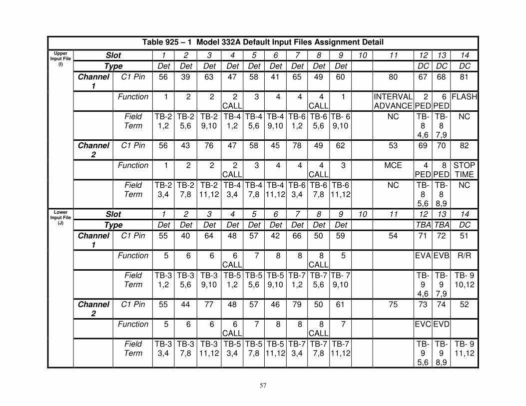
57
Table 925 – 1 Model 332A Default Input Files Assignment Detail
Upper Input File
(I)
Slot 1 2 3 4 5 6 7 8 9 10 11 12 13 14
Type Det Det Det Det Det Det Det Det Det DC DC DC
Channel 1
C1 Pin 56 39 63 47 58 41 65 49 60 80 67 68 81
Function �1 �2 �2 �2 CALL
�3 �4 �4 �4 CALL
�1 INTERVAL ADVANCE
�2 PED
�6 PED
FLASH
Field Term
TB-2 1,2
TB-2 5,6
TB-2 9,10
TB-4 1,2
TB-4 5,6
TB-4 9,10
TB-6 1,2
TB-6 5,6
TB- 6 9,10
NC TB- 8
4,6
TB- 8
7,9
NC
Channel 2
C1 Pin 56 43 76 47 58 45 78 49 62 53 69 70 82
Function �1 �2 �2 �2 CALL
�3 �4 �4 �4 CALL
�3 MCE �4 PED
�8 PED
STOP TIME
Field Term
TB-2 3,4
TB-2 7,8
TB-2 11,12
TB-4 3,4
TB-4 7,8
TB-4 11,12
TB-6 3,4
TB-6 7,8
TB-6 11,12
NC TB-8
5,6
TB-8
8,9
NC
Lower Input File
(J)
Slot 1 2 3 4 5 6 7 8 9 10 11 12 13 14
Type Det Det Det Det Det Det Det Det Det TBA TBA DC
Channel 1
C1 Pin 55 40 64 48 57 42 66 50 59 54 71 72 51
Function �5 �6 �6 �6 CALL
�7 �8 �8 �8 CALL
�5 EVA EVB R/R
Field Term
TB-3 1,2
TB-3 5,6
TB-3 9,10
TB-5 1,2
TB-5 5,6
TB-5 9,10
TB-7 1,2
TB-7 5,6
TB- 7 9,10
TB- 9
4,6
TB- 9
7,9
TB- 9 10,12
Channel 2
C1 Pin 55 44 77 48 57 46 79 50 61 75 73 74 52
Function �5 �6 �6 �6 CALL
�7 �8 �8 �8 CALL
�7 EVC EVD
Field Term
TB-3 3,4
TB-3 7,8
TB-3 11,12
TB-5 3,4
TB-5 7,8
TB-5 11,12
TB-7 3,4
TB-7 7,8
TB-7 11,12
TB-9
5,6
TB-9
8,9
TB- 9 11,12

58
Table 925-2 Required Surge Arrestors for Model 332A Cabinet
Field Terminal Block Terminals Required Arrestor
TB-8 1-12 EDCO PC642C-030 plug in arrestors in PCB1B Terminal Block
TB-9 10-12 EDCO PC642C-030 plug in arrestors in PCB1B Terminal Block
TB-9 4-9 EDCO PCB1B Terminal Block only
TB-2, TB-3, TB-4, TB-5, TB-6, TB-7
1-12 EDCO SRA-6LB
Note: For a typical signal installation, the Model 332 cabinet is the design standard.
Figure 925-1—Wiring Diagram for Dial-up Communications
TERMINAL BLOCK
TB0
Red
Green
Yellow
Black
2
4
1
3
5
7
9
6
8
10
BUCHANAN TERMINAL BLOCK

925.2.05 Type ITS Cabinet Assemblies
Refer to GDOT Specification 925.2.05
925.2.06 – Uninterruptible Power Supply (UPS) System
A. Requirements
This specification is for establishing the minimum requirements for a traffic signal uninterruptible power supply (UPS). The UPS system shall provide a cabinet meeting all the criteria of this specification. All system components of the UPS system shall be housed within the cabinet. The UPS system shall provide reliable emergency power to a traffic signal intersection (vehicle and pedestrian) in the event of utility power failure or interruption. The UPS system shall also act as a power conditioner and/or voltage regulation device.
The UPS system shall be capable of operating a signalized intersection with a 700 watt load for 2 hours of full runtime when utility power is disabled and under ambient temperatures of 25°C. The UPS system shall switch the intersection to flash mode of operation when approximately 40% of battery charge is remaining, via relay contact connection points on front panel of unit. The UPS system shall operate the intersection in the flash mode of operation under a 350 watt load for an additional 2 hours. UPS system components shall be rated for a minimum 1,100 watt load capacity.
The UPS system shall be designed for outdoor applications in accordance with NEMA TS2 2003, or latest revision, Section 2. All components of the ups system shall be rated to operate under temperature extremes of -40°C to +74°C.
1. Definitions
a. Uninterruptible Power Supply System (UPS System): A device that provides battery backup when utility line voltage fails. A device that provides voltage regulation and/or power conditioning when utility line voltage drops below or above nominal operating voltages. The UPS system includes, but is not limited to a manual bypass switch, automatic/manual bypass switch, power transfer relay, an inverter/charger, batteries, battery monitoring device, wiring, external cabinet and all necessary hardware for system operation.
b. UPS System Software: All software associated with operation, programming and functional requirements of the UPS system.
c. Battery Monitoring Device: The device which monitors battery temperature and charge rate of the batteries used in the UPS system.
d. Batteries: Standard 12 Volt batteries wired in series to create a 48V DC to 96V DC voltage storage.
e. Boost: When enabled, the UPS inverter/charger shall automatically switch into this mode to raise the utility line voltage when it drops below a preset limit. The limit may be user defined or use manufacturer default settings (typical 100V AC).
f. Buck: When enabled, the unit shall automatically switch into this mode to reduce the utility line voltage when it rises above a preset limit. The limit may be user defined or use manufacturer defaults (typical 135V AC).
g. Inverter / Charger: The unit which converts the DC voltage input into 120V AC output for the traffic signal cabinet to operate. As a minimum the inverter/charger shall be rated for 1,100 watts.
h. Inverter Line Voltage: The power supplied from the UPS system to the traffic signal cabinet from the UPS system inverter.
i. Manual Bypass Switch: Manual switch that allows user to bypass UPS power to service system equipment. Manual bypass switch switches utility line power directly to cabinet.
j. Power Transfer Relay: A relay connected between the manual bypass switch and the inverter/charger that switches power from utility line voltage to UPS voltage. The power transfer relay may be internal to the inverter charger or combined with the manual bypass switch. In the event of battery voltage loss, the power transfer switch will automatically return to utility line power.
k. Signal Operation Mode: A typical signalized intersection generating a 700 watt load when running in normal operation.
l. Signal Flash Mode: A signalized intersection generating a 350 watt load when running in the flash mode of operation.
m. Utility Line Voltage: The 120V AC power supplied to the UPS system.

60
2. Operation: Line Interactive (Buck and Boost) Method
a. When the buck and boost functions are enabled they shall set the upper and lower control limit allowable for the utility line voltage. If the utility line voltage falls within the parameters set by buck and boost then the UPS system shall continue to operate the intersection under utility line power. If the utility line voltage fluctuates above or below the buck and boost values, the UPS system shall raise or lower the voltage by approximately 10%-15% of the utility line voltage in an attempt to bring the voltage back into the upper and lower control limits set by buck and boost. Buck and boost shall have preset manufacturer defaults.
b. If the utility line voltage falls above or below the functional capabilities of buck and boost then the UPS system shall transfer power from utility line voltage and the inverter/charger shall operate the intersection from battery power converting DC voltage to AC.
3. General Operating Requirements
a. The UPS system shall be capable of providing 1,100 watts active output capacity, with a minimum of 80% inverter efficiency. The inverter/charger shall be rated for a minimum of 1,100V AC and capable of operating at 1,100 watts continuous load.
b. When batteries are fully charged, ensure the UPS system provides power to run a signalized intersection with a 700 watt load for a minimum of 120 minutes (2 hours) of fully actuated runtime, then operate the signalized intersection with a 350 watt load for a minimum of 120 minutes (2 hours) of flash runtime.
c. When the system is running on battery power, the UPS system shall allow the user to select a voltage (typical 48V) at which the transition from normal operating loads to flash mode of operation will occur via a set of relay contacts and connection points on the front panel of the inverter/charger.
d. The transfer time allowed, from disruption of normal utility line voltage to stabilized inverter line voltage from batteries, shall be less than 65 milliseconds. The same allowable transfer time shall also apply when switching from inverter line voltage to utility line voltage.
e. The UPS system shall bypass utility line power whenever the utility line voltage is outside of the manufacturer’s default or a user programmed voltage range ±10% AC.
f. When the utility line power has been restored to a normal operating voltage for more than 30 seconds, the UPS system shall transfer from battery back to utility line mode. The UPS shall be equipped to prevent a malfunction feedback to the cabinet or from feeding back to the utility service.
g. The UPS system shall be compatible with TS1, TS2 and Model 170/2070 controllers and cabinet components for full run time operation.
h. A combination, Auto/Manual integrate bypass switch shall be able to be either rack or shelf mounted in the cabinet. The interconnect cables shall be no less than 10 feet in length. Relay contact wiring for each set of normally open (NO) and normally closed (NC) relay contact closure terminals shall be no less than 6 feet long of #18 AWG wire. Wire size shall be sized accordingly to manufacturer recommendations for any cable lengths greater then 10 feet.
i. The UPS system shall have lightning surge protection compliant with IEEE/ANSI C.62.41, latest revision and meeting all current UL1449 standards. Lightening surge protection shall be provided to the utility line voltage coming into the inverter/charger. The surge protection device shall be easily accessible and mounted externally from the inverter/charger.
j. The UPS system and batteries shall be easily replaced and provided with all needed hardware. The UPS system shall not require any special tools for installation.
k. The UPS system shall operate with an automatic “fail safe” mode. Should a breaker trip on the inverter/charger and/or the power transfer relay, the unit will automatically default to utility line power and bypass the UPS system.
l. The UPS system unit shall be capable of logging up to 100 events. Events shall date and time stamp faults with AC line voltage and UPS battery voltages. At a minimum, the following conditions shall be recorded as an event:
1) The UPS system shall record utility line voltage occurrences whenever the line voltage falls above or below the upper and lower control limits or manufacturer preset defaults. When this condition occurs, it shall be recorded as an event.
2) Whenever the UPS system automatically switches to battery power this shall be recorded as an event.

61
3) Self monitoring, UPS system component failures shall be recorded as an event
4. Displays, Controls, Diagnostics, and Maintenance
a. The UPS system shall include a front panel display. All applicable programmable functions of the operational methods described in this specification shall be viewable through the front panel display.
b. All events described in Subsection 925.2.06.A.3.l shall be viewable from the front panel display.
c. The UPS system software shall be programmable from the front panel of the inverter/charger by means of a keyboard or momentary buttons allowing user to step through menu driven software.
d. A 10/100 Ethernet port shall be provided on the front panel of the inverter/charger.
e. A RS232 port shall be provided on the front panel of the inverter/charger.
f. UPS system software shall be provided for the operational needs of the UPS system. The user/ operator shall be able to access all system software via the Ethernet port and RS232 port on the front panel of the inverter/charger. The user shall be able to read logged events and/or change programmable parameters from the keyboard, laptop or local area network via the Ethernet port.
g. System software shall be upgradeable via the RS232 port on the front panel of the inverter/ charger.
5. Inverter / Charger
a. When utility line voltage is out of normal operating range (typical 100V AC to 135V AC), the inverter/charger shall provide voltage regulation and/or power conditioning to the inverter line voltage using one or more of the methods described in Section 3.0 of this specification. When utility line voltage is present it shall act as a charging device for the batteries.
b. Ensure a minimum of 6 sets of NO and NC single-pole double-throw dry contact relay closures shall be made available on the front face of the inverter/charger and labeled so as to identify each contact. The relay closures shall consist of:
1) A set of NO and NC contact closures shall be energized whenever the unit switches to battery power. Contact shall be labeled or marked as “On Battery” or equal.
2) A second set of NO and NC contact closures shall be energized whenever the battery approaches approximately 40% of remaining capacity. This limit will determine when the unit will switch from normal operation to flash. Contact shall be labeled or marked as “Low Battery” or equal.
c. Operating temperature range for both the inverter/charger unit and power transfer relay shall be -40°C to + 74°C.
d. When battery power is used, the UPS system output voltage shall be between 110V AC and 125V AC, pure sine wave output, ≤ 3% THD, 60Hz ± 3Hz.
e. As a minimum, the inverter charger shall be rated for 1,100V AC and a power factor of 1 allowing 1,100 watts of continuous power from the unit.
6. Power Transfer Switch or Automatic / Manual Bypass
The UPS system shall operate using one of the following methods:
a. Power Transfer Switch and Manual Bypass Switch Method
1) The power transfer switch and a manual bypass switch shall be provided as a separate unit external to the inverter/charger unit. The power transfer switch shall be rated at a minimum of 230V AC/16 amp.
2) A manual bypass switch shall be provided in addition to the power transfer switch. The manual bypass shall be 2 position switch. The switch positions shall be labeled “Bypass” and “UPS”.
3) When the switch is in the “Bypass” position, the utility line voltage will feed power directly to the traffic signal cabinet service panel and power to the inverter/charger will be deactivated allowing the user to service UPS equipment and replace the automatic power transfer switch without interrupting power to the intersection.
4) When the switch is in the “UPS” position, utility line power will be fed through the contacts of the external power transfer relay/contactor and to the cabinet service panel. Should a utility line condition occur activating buck or boost or in the event of utility line loss, the power transfer relay/contactor will be energized and power from the output of the inverter/charger will be connected to the cabinet service panel. Utility line power will be disconnected when power transfer relay/contactor is energized.

62
b. Automatic/Remote Manual Bypass Switch Method
1) The automatic bypass switch shall be provided as a separate unit external to the inverter/charger unit. The automatic bypass switch shall be 2 position and rated at a minimum of 230V AC/16 amp. A UPS supply breaker rated at 240V AC/20 amps shall be provided for the 120V AC input to the inverter/charger.
2) When the automatic bypass switch is in the “on” position and the supply breaker is “on”, the UPS system is connected to utility line voltage and its output is connected to the cabinet service panel. If the utility line voltage is deactivated, the UPS system will automatically switch over to battery power.
3) When the automatic bypass switch is in the “off” position, and the supply breaker is “on”, utility line power is provided to the cabinet service panel and the inverter/charger allowing equipment to be tested without interrupting power to the traffic signal load.
4) When the automatic bypass switch is “off” and the supply breaker is “off”, the utility line voltage will feed power directly to the traffic signal cabinet service panel and power to the inverter/charger will be deactivated allowing the user to service UPS equipment.
5) A manual bypass switch shall be provided as a combination unit. The switch shall allow for the removal of the UPS without interrupting power to the intersection.
7. Batteries
a. Batteries shall be provided by the manufacturer/vendor providing the UPS system.
b. Individual batteries shall be 12V type, and shall be easily replaced and commercially available for purchase as common off the shelf equal.
c. Batteries shall be sized and rated to operate at 700 watt load for a minimum of two hours (normal operation) followed by a 350 watt load for a minimum of two hours (flash mode).
d. Battery configurations shall consist of 12V batteries arranged in arrangements of 48V.
e. Batteries shall be deep discharge sealed prismatic valve regulated lead acid (VRLA) AGM or Gel cell batteries.
f. Batteries shall operate over a temperature range of -40°C to +74°C.
g. Batteries shall indicate maximum recharge data and recharging cycles and manufacture defaults on the inverter shall not allow the recharging process to exceed the batteries maximum values.
h. Battery interconnect wiring shall connect to the inverter unit via modular harness with red and black cabling that terminates into a typical power pole style connector. Harness shall be equipped with mating power flag style connectors for batteries and a single insulated plug-in style connection to inverter/charging unit. Harness shall allow batteries to be quickly and easily connected in any order and shall be keyed to ensure proper polarity and circuit configuration.
i. Insulated covers shall be provided at the connection points (post) to prevent accidental shorting.
j. Battery cables provided to connect battery to battery harness main cable shall be a minimum of 24 inches. Battery harness shall be sized accordingly with system requirements.
k. Batteries weighing more than 50 pounds or more shall be provided with a handle or hand strap allowing the user to carry or move the battery without the use of other equipment.
8. Battery Monitoring System
a. The UPS system shall use a temperature compensated battery charging system. The charging system shall compensate over a range of 2.5 to 4.0 mV/°C per cell.
b. The temperature sensor shall be used to monitor the temperature and regulate the charge rate of the batteries. Unless required otherwise by the plans the temperature sensor wire shall be as follows:
1) 6.5 foot if external side mount cabinet is attached to existing controller cabinet
2) 6.5 foot if batteries are housed in traffic signal base used for cabinet foundation and batteries are stored on shelf within base.
3) Should the temperature sensor fail, the inverter/charger shall not allow the UPS system to overcharge the batteries. The UPS system shall provide an alarm should the temperature sensor fail.
4) Recharge time for the batteries to 80% or more of full battery charge capacity shall not exceed 20 hours at 70°F.

63
5) Batteries shall not be charged when battery temperature exceeds 50°C ± 3°C.
6) The UPS system shall monitor battery strings within the system and report a weak battery via the “Weak Battery” alarm on the UPS. In addition, the system shall have the capability by utilizing a separate circuit but working with the UPS charger, mounted internally or externally to the UPS, to monitor individual batteries in a string to maintain a balanced battery string, keeping each battery charged equally during aging of the batteries. The balancing of the batteries shall be performed continuously during the life of the battery string.
9. Mounting / Configuration
a. General
a. Inverter/Charger Unit shall be shelf-mounted or rack-mounted on a standard EIA 19” rack.
b. Power Transfer Relay and Manual Bypass Switch shall be mounted on EIA rail.
c. All interconnect wiring shall be provided between Power Transfer Relay, Bypass Switch and Cabinet Terminal Service Block and shall be no less than 3 meters (9’10”) of UL Style 1015 CSA TEW with the following characteristics:
• AWG Rating: 6 AWG
• Stranding: 133 strands of 30 AWG tinned copper
• Rating: 600 V, 105 °C, PVC Insulation
d. Relay contact wiring provided for each set of NO/NC relay contact closure terminals shall be a minimum of 3 meters (10 feet) of UL Style 1015 CSA TEW 18 AWG wire, same ratings as above, except 16 strands of 30 AWG tinned copper. Wiring shall be of adequate length for particular installation.
e. All necessary hardware for mounting (shelf angles, rack, etc) shall be included in the bid price of the UPS. All bolts/fasteners and washers shall meet the following requirements:
• Screw type: Pan Head Phillips machine screw
• Size and Thread pitch: 10-32
• Material: 18-8 stainless steel (Type 316 stainless steel is acceptable as an alternate)
• Washer: Use one flat washer (18-8 stainless steel) under the head of each 10-32 screw (provided that the screws are properly tightened, lock washers are unnecessary.)
• Number of screws per hinge bracket: Minimum of six (6) screws per hinge bracket spaced evenly along bracket, with one screw near each end.
f. The basic UPS mounting shall be: The entire UPS, including batteries, installed inside the externally mounted cabinet.
g. External cabinet
a. The External Cabinet shall be used for housing batteries and UPS, which includes inverter/charger unit, power transfer relay, manually operated bypass switch, any other control panels, and all wiring and harnesses.
b. The same Inverter/Charger, Power Transfer Relay and manually operated Bypass Switch that fits inside a typical fully equipped CALTRANS Model 332A Cabinet shall also be able to fit inside the externally mounted cabinet.
c. The External Cabinet shall be a NEMA 3R rated cabinet conforming to TEES, August 16, 2002 Chapter 7, Section 2-Housings for the construction and finish of the cabinet. The specific finish of the external cabinet shall match the finish of the 332A cabinet. Anti-Graffiti paint shall not be used. Two separate mounting installations shall be used. Refer to the project plans for the appropriate mounting installation.
d. The cabinet installation shall provide the external battery cabinet as a base mount cabinet on the same foundation as the 332 cabinet. Connections between the cabinets shall be through conduit in the cabinet base. The external cabinet shall be installed in the same relationship as shown in Figure 925-9 to the 332 cabinet. The external cabinet shall be installed so that it is centered on the 30 inch left side of the 332 cabinet. Bolt UPS cabinet to pre-fabricated base.

64
e. Use a prefabricated base with the following dimensions: 40” x 44” x 24”. The opening for the signal cabinet shall be 21” x 15” and the opening for the external battery cabinet shall be 16” x 6”.
f. Two shelves shall be provided.
g. The bottom shelf shall be capable of being removed.
h. Cabinet Specifications:
• Height = 56”
• Width = 26”
• Depth = 14”
• Door Handle shall be Stainless Steel
• Door shall have Louvered Vents
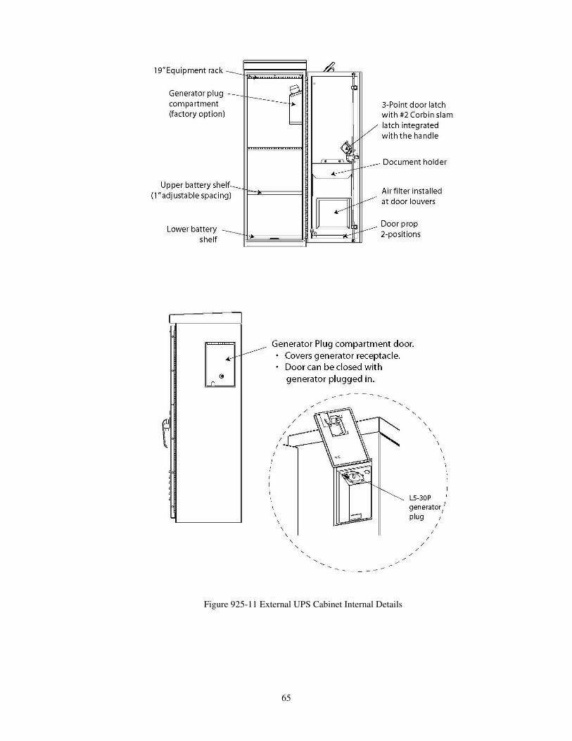
65
Figure 925-11 External UPS Cabinet Internal Details

66
Figure 925-12 External UPS Cabinet Mounting Pad
h. The External cabinet shall be ventilated through the use of louvered vents, filter, and one
thermostatically controlled fan as per TEES Chapter 7 Section 2-Housings. The thermostat shall be accessible without removing the UPS controller.
i. External cabinet fan shall be AC operated from the same line output of the Manual Bypass Switch that supplies power to the 332 Cabinet. A 2-position terminal block shall be provided on the fan panel, along with 3 meters (10 feet) of connected hookup wire.
j. The door shall be attached to the cabinet through the use of either a continuous stainless steel piano hinge or four, two-bolts per leaf, hinges as per TEES Chapter 7 Section 2. The door shall use a padlock clasp or latch and lock mechanisms as described in the TEES, in order to lock the door.
k. Two EIA angle rails, per Detail C, Figure 925–11, along with all necessary mounting hardware (4 sets of 10-32 bolts and nuts with captive washers) shall be provided with the external cabinet (not installed). Rails shall be symmetric to allow for installation on either right or left sides of the cabinet. Mounting holes and bracket shall allow for EIA rail installation at any location in the external cabinet. The EIA mounting angle nominal thickness shall be either 0.1345 inch (3.4163mm) plated steel or 0.105 inch (2.667mm) stainless steel.
l. EIA rail mounting bracket shall be of continuous, one-piece design bolted into the cabinet to provide adequate support for rail-mounted equipment. See Figure 925–12.
B. Fabrication
Refer to Subsection 925.2.07.A.1 for controller cabinet minimum fabrication Specifications.
C. Acceptance
General Provisions 101 through 150.
Each UPS shall be manufactured in accordance with a manufacturer Quality Assurance (QA) program. The QA program shall include two Quality Assurance procedures: (1) Design QA and (2) Production QA. The Production QA shall include statistically controlled routine tests to ensure minimum performance levels of UPS units built to meet this specification and a documented process of how problems are to be resolved. The manufacturer, or an independent testing lab hired by the manufacturer, shall perform Design Qualification Testing on new UPS system(s) offered, and when any major design change has been implemented on an existing design. A major design change is defined as any modification, material, electrical, physical or theoretical, that changes any performance characteristics of the system, or results in a different circuit configuration. Where a dispute arises in determining if a system is a new design or if the system has had a major design change, the State will make the final determination if Design Qualification Testing is required prior to production consideration.
Production Quality Control tests shall be performed on each new system prior to shipment. Failure to meet this requirements shall be cause for rejection. The manufacturer shall retain test results for seven years. Each UPS shall be given a minimum 100-hour burn-in period to eliminate any premature failures. Each system shall be visually inspected for any exterior physical damage or assembly anomalies. Any defects shall be cause for rejection.
D. Materials Warranty
Refer to Subsection 925.2.01.D for Materials Warranties. Manufacturers shall provide a five (5) year factory-repair warranty for parts and labor on the UPS from date of acceptance by the Department. Batteries shall be warranted for full

67
replacement for five (5) years from date of purchase. Batteries shall be defined as bad, if they are not able to deliver 80% of battery rating. The warranty shall be included in the total bid price of the UPS.
925.2.07 Flashing Beacon Assembly
A. Requirements
This specification is for a flashing signal cabinet, which consists of an aluminum cabinet containing a flasher assembly, Field connection terminal block, surge arrestor and circuit breaker wired in a manner to operate flashing beacons. Refer to Figure 925-13.
Note: Front view of cabinet Door Assembly not shown
No scale Figure 925-13—Typical Flashing Signal Cabinet Layout
1. Cabinet
Supply a NEMA Type 3R cabinet assembly, manufactured of aluminum with a minimum thickness of 0.125 inches (3 mm).
Ensure that the cabinet exterior has a smooth, uniform “bare” aluminum finish with all joints between adjoining cabinet components (sides and bottom) continuously welded on the outside to prevent the intrusion of moisture and dust.
NEMA FLASHER
AC BRKR
TB
SPA 100

68
Ensure that all welds are free of cracks, blow holes and other irregularities.
Supply a cabinet with the following exterior dimensions:
Minimum Maximum
Height 14 inches (350 mm) 18 inches (450 mm)
Width 10 inches (250 mm) 14 inches (350 mm)
Depth 10 inches (250 mm) 10 inches (250 mm)
Use a cabinet door that is double flanged on all four sides to prevent the entry of dirt and liquids when the door is open.
Install a one-piece gasket formed around the door opening to insure a weather tight seal when the door is secured.
Attach the door to the cabinet housing by a continuous tamper proof hinge.
Equip each cabinet with a Corbin #2 lock and one key. Police panel type locks are not acceptable.
Install an aluminum back panel in the cabinet, mounted on standoffs, to facilitate mounting of internal components.
Install exterior aluminum mounting brackets, which extend a minimum of 1.75 inches (44 mm) and a maximum of 2.5 inches (63 mm) from the top and bottom of the cabinet.
Use brackets that extend across the full width of the cabinet back on the top and bottom.
Provide these brackets with holes for mounting to a flat surface with screws and vertical slots for banding to steel, concrete or wooden signal poles.
2. Flasher Unit
Supply a standard plug in two circuits NEMA flasher.
Ensure that the flasher is of all solid state construction, meets the requirements of the NEMA standards and is rated at a minimum of 10 A per circuit.
Ensure that the flasher utilizes zero voltage turn-on and turn-off current and is capable of dimming outputs.
3. Surge Arrestor Supply a flasher cabinet that incorporates an AC surge arrestor (EDCO SPA-100 or equivalent) to protect the internal components from lighting and over voltages on the AC service input. The requirements for the surge arrestor are:
Peak Surge Current 15000 A
Peak Surge Voltage @ 10KA 680 V
Energy Handling 220 J
Power Dissipation Rate 1.5 W maximum
Continuous AC Voltage 130 V AC RMS
Initial Breakdown (1mA) 212 V
Typical Capacitance 4000 pF
Operating Temp. -40 ºF to 185 ºF (-40 ºC to 85 ºC)
4. Circuit Breaker
Include a 15 A circuit breaker in the cabinet. (Square D QOU 115 Series or equivalent).
5. Terminal Block
Include a four position terminal block in the cabinet for making field connections. Properly label all field terminal connections.
6. Construction
Assemble the flasher assembly, terminal block, surge arrestor and circuit breaker in the cabinet as shown on the attached drawing.
Wire all components together as a working unit, thus requiring only field connections to and from the AC power and flashing beacons.
B. Fabrication
Refer to Subsection 925.2.07.A.1 for controller cabinet minimum fabrication specifications.

69
C. Acceptance
General Provisions 101 through 150.
D. Materials Warranty
Refer to Subsection 925.2.01.D for Materials Warranties.
925.2.08 Flashing Signal Cabinet with Pager
A. Requirements
This specification is for a flashing signal cabinet with pager which consists of an aluminum cabinet containing a flasher assembly, pager, field connection terminal block, surge arrestor and circuit breaker wired in a manner to operate school
flashing beacons. Refer to Figure 925-14.
1. Cabinet
Supply a NEMA Type 3R cabinet assembly that is manufactured of aluminum with a minimum thickness of 0.125 inches (3 mm).
Ensure that the cabinet exterior has a smooth, uniform natural aluminum finish, and that all joints between adjoining cabinet components (sides and bottom) are continuously welded on the outside to prevent the intrusion of moisture and dust.
Ensure that all welds are free of cracks, blow holes and other irregularities.
The exterior dimensions of the cabinet are as follows:
Minimum Maximum
Height 14 inches (350 mm) 18 inches (450 mm)
Width 10 inches (250 mm) 14 inches (350 mm)
Depth 10 inches (250 mm) 10 inches (250 mm)
Supply a cabinet door that is double flanged on all four sides to prevent the entry of dirt and liquids when the door is open.
Use a one-piece gasket that is formed around the door opening to insure a weather tight seal when the door is secured.
Attach the door to the cabinet housing with a continuous tamper proof hinge.
Provide each cabinet with a Corbin #2 lock and one key. Police panel type locks are not acceptable.
Supply each cabinet with an aluminum back panel mounted on standoffs to facilitate mounting of internal components.
Supply cabinets with exterior aluminum mounting brackets, which extend a minimum of 1.75 inches (44 mm) and a maximum of 2.5 inches (63 mm) from the top and bottom of the cabinet.
Use brackets that extend across the full width of the cabinet back on the top and bottom.
Provide these brackets with holes for mounting to a flat surface with screws and vertical slots for banding to steel, concrete or wooden signal poles.

70
Note: Front view of cabinet Door Assembly not shown
No scale
Figure 925-14—Typical Flashing Cabinet with Pager Cabinet Layout
2. Flasher Unit
Supply a standard plug in, two circuits NEMA flasher.
Ensure that the flasher is of all solid state construction, meets the requirements of the NEMA standards and is rated at a minimum of 10 A per circuit.
Ensure that the flasher utilizes zero voltage turn-on and turn-off current and be capable of dimming outputs.
3. Time Switch
Supply a time switch that meets the requirements as outlined in Section 925.2.09 below in this specification.
4. Surge Arrestor
Supply flasher cabinets that incorporate an AC surge arrestor (EDCO SPA-100 or equivalent) to protect the internal components from lighting and over voltages on the AC service input.
The requirements of the surge arrestor are as follows:
Peak Surge Current 15000 A
Peak Surge Voltage @ 10KA 680 V
Energy Handling 220 J
Power Dissipation Rate 1.5 W maximum
Continuous AC Voltage 130 V AC RMS
Initial Breakdown (1mA) 212 V
Typical Capacitance 4000 pF
Operating Temp. -40 ºF to 185 ºF (-40 ºC to 85 ºC)
AC BRKR
SPA 100
NEMA FLASHER
PAGER
TB

71
5. Circuit Breaker
Include a 15 A circuit breaker in each cabinet. (Square D QOU 115 Series or equivalent).
6. Terminal Block
Include a four position terminal block in each cabinet for making field connections. Properly label all field terminal connections.
7. Construction
Assemble the flasher assembly, terminal block, surge arrestor and circuit breaker in the cabinet as shown on the attached drawing.
Wire all components together as a working unit, thus requiring only field connections of the AC power and flashing beacons.
B. Fabrication
Refer to Subsection 925.2.07.A.1 for controller cabinet minimum fabrication specifications.
C. Acceptance
General Provisions 101 through 150.
D. Materials Warranty
Refer to Subsection 925.2.01.D for Materials Warranties.
925.2.09 – Time Clock
A. Requirements
Supply time clocks that are single circuit, pager programmable, solid state, fully self-contained units (CPR2102 or equivalent) that meet the following Specifications:
1. -Download Default Week Plan, Alternate Week Plan, Override Plan, Vacation Plan over the paging network
2. LED indicators on unit indicating:
a. Power
b. Communication being received
c. Relay on or off
d. Week Plan being run
e. Group and location address
3. Power back-up maintains timekeeping and program for more than 6 months
4. Maximum size of 3.7 inches wide, 7.5 inches high and 1.55 inches deep.
5. A programming manual is to be included with each unit.
6. Ability to do program transfer from unit to unit. Include program transfer cable with unit.
7. Ability to run up to twenty (20) different day plans and an unlimited number of annual plans.
8. Include cellular communications modem with the following requirements:
a. LED indicators for power and cellular connection
b. Ability to be mounted directly to time clock
c. Powered by time clock with no external power supply required
d. Time sync via cell system GPS
e. Maximum size of 2.45 inches wide, 3.17 inches high and 1.16 inches deep
B. Fabrication
General Provisions 101 through 150.
C. Acceptance
General Provisions 101 through 150.

72
D. Materials Warranty
Refer to Subsection 925.2.01.D for Material Warranties.
925.2.10 Self-Tuning Loop Detector
A. Requirements
This specification sets forth the minimum acceptable design, operational and functional performance requirements for multi-channel, inductive loop vehicle detection systems.
1. General Requirements
a. Mounting
Ensure that the unit is configured for rack mount insertion into a NEMA (TS l or TS 2) card rack and/or CALTRANS Type 2070 cabinet input file.
b. Environmental
Ensure that the unit is in full compliance with the environmental tests, transient tests and size requirements of NEMA standard TS-l Section 15, TS-2 Section 6.5 and the California Type 2070 specifications.
Provide documentation from an independent laboratory, which certifies that the unit is in compliance with the above specifications.
c. LED Indicator
Ensure that each channel includes two high visibility LED indicators; one for the detect state and the second to indicate the status of the fault monitor.
d. Phase Indicator
Ensure that each channel has an erasable write-on pad to aid in identification of the associated phase or function.
2. Operational Requirements
a. Tuning
Supply units that are fully digital and self-tuning.
Ensure that each channel of the unit can automatically tune to any loop and lead in combination within two (2) seconds of application of power or when a reset signal is received.
Ensure that the tuning circuit is designed so that drift, caused by environmental changes or changes in applied power, does not cause false actuations.
b. Scanning
Supply units that sequentially scan each channel (only one channel energized at any given time) to eliminate crosstalk from multiple loops in adjacent lanes and/or allow overlapped loops for directional control and/or allow use of multi-conductor homerun cable when connected to the same detector unit.
c. Sensitivity Setting
Ensure that each channel is equipped with front panel selectable sensitivity settings in presence and pulse modes.
d. Frequency
Supply units that have a minimum of three switch selectable operating frequencies.
e. Inductance Range
Ensure that each channel can tune to an inductive load from 50 to 2000 microhenries with a Q factor > 5.
f. Grounded Loops
Ensure that each channel can continue to operate with poor quality loop systems (Q>2) including those that have a single point short to ground.
g. Fault Monitoring
Supply units that constantly monitor the operation of each channel.

73
Ensure that the unit detects shorted loops, open circuit loops or sudden changes in inductance (>25% of nominal).
Ensure that each type of fault is indicated on a fault LED by a unique sequence of flashes until the fault is rectified.
Ensure that while the channel is in the fault condition, the channel output remains in the detect state.
When the fault is rectified, the fault LED continues to emit the sequence signifying the last fault detected, but the detect LED and output returns to normal operation.
h. Failsafe Output
Ensure that each channel output generates a continuous solid state output to the controller when power to the detector is removed.
i. Operational Modes
Supply units with each channel selectable for either pulse or presence modes and that meet the following requirements:
• Pulse Mode
This setting provides a single output pulse (125 ms +/- 25) in response to a vehicle entering the loop.
If a vehicle remains in the sensing zone in excess of two (2) seconds, the unit "tunes out" said vehicle.
The channel is then capable of detecting another vehicle entering the same detection zone.
• Presence Mode
The presence hold time is a minimum of four (4) minutes for small vehicles (motorcycles) and a minimum of sixty (60) minutes for automobiles.
Ensure that the unit tunes out of continuous peak hour traffic over long or multiple small loops as long as there is vehicle motion in the sensing zone every ten (10) minutes.
j. Resets
Ensure that the channels are manually resettable by removing the power momentarily.
Ensure that the channels reset remotely when the voltage on Pin C falls below 8 V DC for a period > l5µs, and that the unit resumes normal operation within four (4) seconds after the application of power or after a reset signal of l5µs.
k. Field Tuning
Ensure that field adjustments to the operation of the detector do not require the use of a meter, circuit changes, special software or any substitutions, modifications or additions to the unit.
3. Performance Requirements
If testing should be required, provide the Department with a test unit and/or software within ten (10) calendar days of the request.
Should the unit fail to meet the design and/or performance requirements of this specification, the unit will be rejected.
Ensure that the units meet the following requirements:
a. Capable of detecting passage, holding presence and accurately counting all types of licensed motor vehicles when connected in various loop configurations and lead-in combinations without detecting vehicles in adjacent lanes.
Typical Loop Configurations with Lead-in of 5 feet (1.5 m) to 1,500 feet (1000 m) are:
6 feet x 6 feet (1.8 m x 1.8 m)
6 feet x 15 feet (1.8 m x 4.5 m)
6 feet x 50 feet [(1.8 m x 15 m) standard or quadrupole
b. Capable of responding to an inductance change of 0.02% and sense vehicles at speeds of up to 80 mph (130 km/h).
c. Not detect vehicles, moving or stopped, at distances greater than three feet for any loop perimeter.

74
d. Detect all vehicles over multiple turn and/or multiple loops that may he connected in series, parallel or series/parallel with homerun lengths from <5 feet (1.5 m) to > 1,500 feet (1,000 m).
4. Optional Features
In addition to the requirements listed in the previous sections, the units may be requested with any combination of the following optional features:
a. Option 1- Timing Features - Delay & Extension
When this option is specified, ensure that the unit incorporates the following features:
• Delay Timing
Minimum selectable delay time of 1 to 30 seconds in minimum 1-second increments for each channel.
• Extension Timing
Minimum selectable extension time of 0.5 to 10 seconds in minimum 0.5-second increments for each channel.
b. Option 2 - Advanced Features
When the option for advanced features is specified, supply units that incorporate the following advanced features:
• Serial Port Interface
When the serial port interface is specified, equip the detector with a front and rear panel RS 232 port for the transmission of data. Provide Windows 98 or newer compatible software for interfacing with the detector.
• PC Interface
Ensure that PC software, when connected directly to the unit through the front panel RS 232 port, provides a screen to display the following loop system operating characteristics, on a per channel basis, for system setup, data collection and diagnostics.
* Loop Status
* Loop Inductance (µH)
* Loop Frequency (kHz)
* Inductance Change (nH)
* Last Fault: Open, Shorted, >25% L
* Fault Occurrence: Date & Time
* Vehicle Count
• Speed, Volume & Occupancy
The software, when connected directly to the unit, is capable of collecting and storing speed, volume and occupancy data from each detector channel.
The software allows assignment of loop-to-loop distances to enable accurate speed and vehicle length measurements.
The speed volume and occupancy information is uploaded and stored in the vendor-supplied software.
Upon request, supply the necessary information/protocols to allow the Department to write custom software to retrieve speed, volume and occupancy data.
B. Fabrication
General Provisions 101 through 150.
C. Acceptance
General Provisions 101 through 150.
D. Materials Warranty
Refer to Subsection 925.2.01.D for Materials Warranties.
925.2.11 Loop Sealant

75
A. Requirements
Furnish and install loop sealant according to Subsection 833.2.09, “polyurethane Sealant for Inductive Loops”. Sealant shall be 3M Loop Sealant or approved equivalent.
B. Fabrication
General Provisions 101 through 105.
C. Acceptance
General Provisions 101 through 105.
D. Materials Warranty
Refer to Subsection 925.2.01.D for Materials Warranties.
925.2.12 Vehicle Signal Heads
A. Requirements
Supply vehicle signal heads that are 12 inches (300 mm) in diameter.
Ensure that the 12 inch (300 mm) polycarbonate vehicle signal heads meet the current ITE specification on Vehicle Traffic Control Signal Heads with the following modifications and / or clarifications:
1. Unless otherwise approved by the Signal Design Engineer or as noted on the Plans, supply signal heads that are all yellow
2. Provide vehicle signal heads that are modular type constructed primarily on non-metallic components that can be arranged in different combinations with each other to provide vehicle signal displays in accordance with the Manual on Uniform Traffic Control Devices.
3. Each traffic signal shall consist of one or more signal face.
4. Each signal face shall consist of one or more signal section of such design and construction as to fit rigidly and securely together, to prevent the entrance of dirt or moisture and prevent the rotation or misalignment of the individual sections with each other.
5. It shall be possible to arrange a signal face in either a vertical or a horizontal alignment.
6. The major components of the signal head, including but not limited to the housing and door, shall be ultra-violet stabilized polycarbonate resin. The housing of each signal section shall be of one-piece polycarbonate resin die molded complete with integral top, bottom and sides having a minimum thickness of 5/32 inches.
7. Mount one steel reinforcing support plate in the top of the red section of each three, four, or five-section signal head for the installation of mounting hardware.
8. Install a support plate between each section of all signal heads. Place these plates such that there is a plate in the bottom of and/or top of any sections where sections adjoin to another section.
9. Cluster hardware shall be included with all five-section signal heads.
B. Fabrication
Refer to ITE Standards for material composition and finish specifications.
C. Acceptance
Refer to ITE Standards for material composition, finish specifications, and wind loading requirements.
D. Materials Warranty
Refer to Subsection 925.2.01.D for Materials Warranties.
925.2.13 Pedestrian Signal Head
A. Requirements
Provide each section with a visor encompassing the top and sides of the signal face of a size and shape adequate to shield the lens from external lighted sources.
An acceptable option is a “Z-crate” or louver type visor for mounting over the pedestrian signal face.
Construct the housing door, door latch, and hinges of aluminum, or approved equal.
Provide hinge pins of stainless steel.

76
Ensure that the door is provided with a neoprene gasket capable of making a weather resistant, dustproof seal when closed. Unless otherwise specified by the Engineer, supply pedestrian signal heads with a black face and a yellow body.
Ensure that pedestrian indications are distinguishable to the pedestrian both day and night and at all distances from 10 feet (3 m) to the full width of the areas to be crossed.
Supply pedestrian indications that are rectangular in shape and consist of the "HAND & PERSON" symbol.
Use symbols that are 12 inches (300 mm) high.
Use only internal illumination.
Ensure that when illuminated, the “HAND” symbol is Lunar White and the “PERSON” symbol is Portland Orange, meeting the ITE standards.
Ensure that an opaque material obscures all areas of the face or lens, except for the message. Ensure that when not illuminated, the symbols are not to be distinguishable by pedestrians at the far end of the crosswalk they control.
Ensure illuminated symbols are pixilated.
B. Fabrication
General Provisions 101 through 150.
C. Acceptance
General Provisions 101 through 150.
D. Materials Warranty
Refer to Subsection 925.2.01.D for Materials Warranties.
925.2.14 – Removed
925.2.15 – LED Signal Modules
A. Requirements
This specification covers Type 1 and Type 2 Light Emitting Diode (LED) red, green and yellow modules for vehicle signals. It also covers LED pedestrian “HAND & PERSON” signal modules.
1. General Requirements
a. Ensure that Type 1 LED signal modules fit in standard incandescent vehicle traffic signal housings.
Ensure that Type 1 LED signal module include a LED circuit board with LEDs and required circuit components, 36 inch (900 mm) 16 AWG wire leads with strain relief and spade terminals, a rigid housing, and a one piece neoprene gasket.
Supply lenses for Type 1 ball modules that are made of ultraviolet stabilized polycarbonate or glass, and incorporate facets to enhance the optical efficiency of the LED traffic signal module.
Ensure that the external lens surface for all vehicle signals is smooth, with no raised features, to minimize the collection of dirt, diesel smoke, and other particulate contaminates, and to facilitate periodic cleaning.
Supply Type 1 LED signal modules that are watertight when mounted in traffic signal housing
Ensure that the Type 1 LED signal modules utilize the same mounting hardware that is used to secure the incandescent lens and gasket assembly.
Ensure that the housing of Type 1 LED signal modules have prominent and permanent markings to designate the proper orientation of the LED signal module in the traffic signal housing. The marking consists of an up arrow, or the word “Up” or “Top”.
Supply lenses that are keyed to the housing of the LED signal module to insure the proper orientation.
b. Ensure that the Type 2 LED signal modules are designed to mount in the standard lamp socket normally used with an incandescent lamp.
When a Type 2 LED signal module is used, provide a standard lens in the doorframe to seal the signal section from the weather.
Supply Type 2 LED signal modules that do not require any modification to the standard lamp socket or reflector.

77
Supply Type 2 LED signal modules that do not require a specific mounting orientation or have a variance in light output, pattern or visibility for any mounting orientation.
Ensure that Type 2 LED signal modules are a sealed unit containing all components necessary for operation except the corresponding lens mounted in the doorframe.
c. Ensure that the LED pedestrian signal modules fit in standard incandescent pedestrian signal housings.
Supply LED pedestrian signal modules with all hardware and gaskets necessary for installation and to achieve a watertight enclosure.
Supply stand-alone pedestrian “HAND” LED signal kits that are Portland Orange and have a filled-in figure symbol.
Ensure that combination “HAND & PERSON” LED Pedestrian signal modules incorporate a Lunar White walking person symbol.
The “HAND & PERSON” symbol may be an outline type symbol, and to insure color compliance with existing Lunar White standards for pedestrian walking person pedestrian signals, includes a replacement lens for the existing OEM lens.
Ensure that the “HAND & PERSON” symbols are overlaid on top each other so that the illuminated image appears to be in the middle of the signal housing.
2. Optical
Ensure that the light intensity and distribution from LED signal modules and pedestrian signals, as a minimum, meet the current ITE and current Caltrans standards and measurement criteria for LED traffic signal modules.
Provide test data from an independent laboratory to verify that the performance of the product meets current ITE requirements.
Ensure that the light output of all LED vehicle signal modules and LED pedestrian signal kits meet current ITE specifications for chromaticity.
Ensure that the individual LEDs are wired such that a catastrophic failure of one LED will result in the loss of not more than 5% of the signal module light output.
The failure of a single LED in a string causes loss of light from only that LED, not the entire string or indication.
Provide control circuitry that prevents the current flow through the LEDs in the “off” state to avoid any false indications as may be perceived by the human eye during daytime and nighttime hours.
Ensure that the LED traffic signal module is operationally compatible with NEMA TS – 1 and NEMA TS – 2 conflict monitoring parameters.
Ensure that the intensity of the LED signal module does not vary by more than 10% over the allowable voltage range as specified in the electrical section below.
Ensure that the LED signal modules maintain not less than 90% of the required intensity, as defined by the July 1998 ITE intensity standards for LED traffic signal modules.
Ensure this over the temperature range of –40 ºF to 165 ºF (–40 °C to + 74 °C) at 120 V AC, when new and after four (4) years of field installation.
Ensure all signal modules are pixilated in appearance.
3. Electrical
Supply LED signal modules that operate over the temperature range of –40 ºF to 165 ºF (-40 °C to 74 ºC).
Ensure that the power factor is 90% or greater, at nominal rated voltage, at 77 ºF (25 °C), after 60 minutes of operation.
Ensure that the total harmonic distortion (THD) is less than 20% at rated voltage, at 77 ºF (25 °C) and that all LED traffic signal modules are in compliance with FCC noise regulations.
Supply Red, Yellow, and Portland Orange LEDs that utilize AllnGaP technology, either AS (Absorbing Substrate) or TS (Transparent Substrate), and do not exhibit degradation of more than 30% of their initial light intensity following accelerated life testing (operating at 185 ºF [85 °C] and 85% humidity, for 1,000 hours).
AlGaAs technology is not acceptable.
Supply green LEDs that utilize gallium nitride technology.

78
Bi-Modal signal heads shall meet the standards for both Yellow and Green LEDs mentioned above.
Ensure that the LED signal modules operate on line voltage, 120 V AC nominal, and are able to operate over the voltage range of 80 V AC to 135 V AC.
Supply Red Arrow LED traffic signals that are temperature compensated so as to maintain intensity at elevated temperatures.
Supply red arrow type LED traffic signals that are tested and documented as being in compliance with Caltrans intensity standards for red arrows at elevated temperatures.
Provide transient voltage suppression rated at 1,500 W for 1 millisecond and fusing with a maximum rating of 2 A to minimize the effect and repair cost of an extreme over voltage situation or other failure mode.
B. Fabrication
General Provisions 101 through 150.
C. Acceptance
General Provisions 101 through 150.
D. Materials Warranty
Ensure that LED traffic signal modules and LED pedestrian modules are performance warranted to be in compliance with July 1998 ITE and Caltrans minimum intensity standards for LED traffic signal modules, measured at 120 V AC and 165 ºF (74 °C), for a period of five (5) years.
Ensure that the manufacturer’s name, part number, date code, and electrical characteristics of the LED signal module is visible on the assembly, and that each LED signal module is identified for warranty purposes.
925.2.16 LED Pedestrian and Countdown Signal Module
A. Requirements
This specification covers LED traffic signal module designed as a retrofit replacement for the message bearing surface of nominal 16” x 18” (400 mm x 450 MM) traffic signal housing built to the PTSCI Standard. The message bearing surface of the module consists of an overlapping “Hand” and “Man” Symbols with a numerical display of numbers from 00 to 99.
1. General Requirements
Ensure that the unit supplied meets the applicable portions of section 925.15 of this specification.
Ensure that the message numbers “00” to “99” are a minimum of 9 inches (228 mm) in height and consist of two rows of LEDs.
Ensure the module fits in the Pedestrian Signal Housing without modification to the housing and requires no special tools for installation.
Supply LED signal modules that are watertight when mounted in the traffic signal housing.
Supply life data from the LED Signal Module manufacturer to calculate the expected useful life
Supply modules with permanent markings for date of manufacture and date of installation.
2. Optical
Provide test data from an independent laboratory to verify that the performance of the product meets current ITE requirements.
Ensure that the individual LEDs are wired such that a catastrophic failure of one LED will result in the loss of not more than 5% of the signal module light output.
The failure of a single LED in a string causes loss of light from only that LED, not the entire string or indication.
Provide control circuitry that prevents the current flow through the LEDs in the “off” state to avoid any false indications as may be perceived by the human eye during daytime and nighttime hours.
Ensure that the LED signal module is operationally compatible with existing or new supplied conflict monitors (NEMA TS-1, NEMA TS-2, Model 210, Model 2010, ITS Cabinet CMU and AMU.
Ensure that the LED Signal Module is operationally compatible with existing or new supplied load switches.

79
Ensure that the intensity of the LED signal module does not vary by more than 10% over the allowable voltage range as specified in the electrical section below.
Ensure that the LED signal modules maintain not less than 90% of the required intensity, as defined by the ITE intensity Standards for LED traffic signal modules.
Ensure that each module provides an average luminous of at least 3750 candela per square meter of lighting surface for the “Hand" and 5300 candela per square meter for the Man symbol.
Ensure this over the temperature range of –40 ºF to 165 ºF (–40 °C to + 74 °C) at 120 V AC, when new and after four (4) years of field installation.
Ensure all signal modules are pixilated in appearance.
3. Electrical
Supply LED signal modules that operate over the temperature range of –40 ºF to 165 ºF (-40 °C to 74 ºC).
Ensure that the power factor is 90% or greater, at nominal rated voltage, at 77 ºF (25 °C), after 60 minutes of operation.
Ensure that the total harmonic distortion (THD) is less than 20% at rated voltage, at 77 ºF (25 °C) and that all LED traffic signal modules are in compliance with FCC noise regulations.
Ensure that the LED signal modules operate on line voltage, 120 V AC nominal, and are able to operate over the voltage range of 80 V AC to 135 V AC.
Provide transient voltage suppression rated at 1,500 W for 1 millisecond and fusing with a maximum rating of 2 A to minimize the effect and repair cost of an extreme over voltage situation or other failure mode.
Ensure the modules allow a reduction of the intensity of the light output in response to an input from the traffic signal controller. Ensure the minimum light output when dimmed is not less than 30% of the minimum maintained luminous intensity as defined in the applicable ITE Signal Head Module.
4. Operation
Supply LED Modules which start counting when the flashing “Don’t Walk” Indication starts and will countdown to “0” when the steady “Don’t Walk” signal turns on. Ensure that the countdown numbers remain continuously illuminated through the flashing don’t walk interval. Ensure that the unit maintains a consistent countdown during a short power failure (i.e. Traffic Controller does not restart). Ensure that if Traffic Controller restarts that the countdown timer display is turned off until one full pedestrian clearance Cycle is timed. Ensure that the unit will turn off the counter if the steady Don’t Walk Display starts while the countdown timer is displaying a number other than 00.
B. Fabrication
General Provisions 101 through 150.
C. Acceptance
General Provisions 101 through 150.
D. Materials Warranty
Ensure that LED traffic signal modules and LED Pedestrian modules are performance warranted to be in compliance with the latest ITE and CALTRANS minimum intensity Standards for LED traffic signal modules, measured at 120 V AC and 165 ºF (74 °C), for a period of five (5) years.
Ensure that the manufacturer’s name, part number, date code, and electrical characteristics of the LED signal module is visible on the assembly, and that each LED signal module is identified for warranty purposes.
925.2.17 – Removed
925.2.18 – Removed
925.2.19 – Pedestrian Push Button Station
A. Requirements
1. Momentary Pedestrian Push Button
a. Button shall be highly vandal resistant and pressure activated with essentially no moving parts. Button shall be able to withstand an impact from a baseball bat or hammer.

80
b. Button housing shall be cast aluminum powder coated.
c. Button cap shall be made of 316 stainless steel.
d. Switch shall be solid state Piezo electronic switch rated for 100 million cycles with no moving plunger or moving electrical contacts.
e. Button shall have LED that flashes approximately 0.025 seconds each time the button is pressed.
f. Button shall give a two toned beep indication of button being pushed (one tone for push, one tone for release).
g. Button shall have built in surge protection.
h. Button shall be able to hold the call for a minimum of 5 seconds.
i. Button shall operate immediately after being completely immersed in water for 5 minutes.
j. Button shall not be able to allow ice to form such that it would impede function of button or button cap\
k. All switch electronics shall be sealed within the cast aluminum housing. Total depth of button, from face of button cap to back of button terminal, shall be less than 1.75 inches.
l. Button shall have raised ridges to protect the button from side impacts.
m. Button shall have transient suppression that meets or exceeds IEC 61000-4-4
n. Button shall have lightning and power protection that meets or exceeds 6000v-400A, 25 reps, 120VAC-15 mins.
2. Button Adapter
a. An adapter shall be provided when requested that allows the latching button to be installed on an existing push button housing manufactured by PELCO, Inc. or TEECO.
b. The adapter shall attach to the existing PELCO or TEECO housing utilizing two screws and shall allow for the latching button to be attached utilizing four screws.
c. The adapter shall be a polycarbonate material and shall be available in yellow, black, green, or silver to accommodate existing bases.
3. Aluminum Button Cup
a. The aluminum button cup shall be supplied when requested for new product installations. The aluminum button cup shall install on the pole and the latching button shall attach to it with four screws.
b. The aluminum button cup shall utilize stainless steel nuts installed in the cup for the latching button to be attached to. This shall eliminate screw holes from being stripped out.
B. Fabrication
General Provisions 101 through 150.
C. Acceptance
General Provisions 101 through 150.
D. Materials Warranty
Refer to Subsection 925.2.01.D for Materials Warranties.
925.2.20 – Signal Head Back Plate
Refer to GDOT Specification
925.2.21 – Signal Head Visors
Refer to GDOT Specification
925.2.22 – Signal Head Louvers
Refer to GDOT Specification
925.2.23 – Hardware for Signal Head Mounting
A. Requirements
Ensure that signal heads are rigidly mounted to the mast arm. Provide mounting hardware that is ASTRO-BRAC or approved equivalent.

81
This item will be approved upon submittal of catalog cuts. Refer to Standard Detail Drawings for additional information.
B. Fabrication
General Provisions 101 through 150.
C. Acceptance
General Provisions 101 through 150.
D. Materials Warranty
Refer to Subsection 925.201..D for Materials Warranties.
925.2.24 – Hardware for Signal Head Pole Mounting
Refer to GDOT Specification
925.2.25 – Balance Adjuster
Refer to GDOT Specification
925.2.26 – Hardware for Mounting 12 Inch (300 mm) Pedestrian Head
Refer to GDOT Specification
925.2.27 – Pedestal Pole
A. Requirements
The pedestal poles support vehicle signal heads, pedestrian signal heads, and push button. Furnish pedestal poles that meet the following specifications:
1. Provide poles that are ten (10) feet in height above grade.
2. Ensure that all poles are made of one continuous piece of bare finish aluminum alloy 6061 heat tempered to T6, of four (4) inch schedule 40-pipe size from top to base connection for the entire height of the pole. Black powder coated pedestal poles may be required as directed by the Engineer.
3. One end shall be threaded, and shall screw into the top of a cast aluminum base.
B. Fabrication
General Provisions 101 through 150.
C. Acceptance
General Provisions 101 through 150.
D. Materials Warranty
Refer to Subsection 925.2.01.D for Materials Warranties.
925.2.28 – Pedestal Base
A. Requirements
Furnish pedestal bases that meet the following specifications:
1. The base shall be square in shape, 14-1/4” in height, and shall be made of aluminum 356 with a T6 temper. Black powder coated pedestal bases may be required as directed by the Engineer.
2. A removable, locking access door shall be provided.
3. Four (4) anchor bolts size ¾" x 20" with hex nuts and flat washers (galvanized) shall also be provided.
The entire assembly when carrying signals shall be capable of withstanding one hundred (100) mph wind loads without failure.
B. Fabrication
General Provisions 101 through 150.
C. Acceptance
General Provisions 101 through 150.
D. Materials Warranty
Refer to Subsection 925.2.01.D for Materials Warranties.

82
925.2.29 – Pedestal Pole Foundation Anchor Assembly
A. Requirements
Provide Foundation Anchor assembly that is 4 inches (100 mm) in diameter by 56 inches (1400 mm) with a single helical blade and a square fixed baseplate with combination underside holt-head retainer and dirt scrappers allowing flush- mount with the ground.
Provide baseplate that is steel and conforms to ASTM A-36 material. Provide pipe with helical blade that is manufactured from ASTM A-53ERW Grade B Steel. Ensure 4 inch pipe has 2 inch (50 mm) by 3 inch (75mm) entrance hole 18 inches below the steel plate. Ensure the anchor assembly is hot dipped galvanized finish after fabrication and complies with ASTM A-123.
Ensure base plate has four slotted mounting holes to fit bolt circles from 7 ¾ inch (195mm) to 14 ¾ inch (375 mm. Provide 4 slotted mounting hole with a ¾ inch keyhole slot to permit bolt installation and replacement from the top surface without digging under the baseplate.
Ensure assembly is furnished with;
• Quantity of four ¾ inch(20 mm) -10NC x 3 inch(75 mm) square head galvanized ASTM 325 anchor bolts;
• Quantity of four ¾ inch(20 mm) plain flat galvanized washers;
• Quantity of four 3/16 inch(5 mm) thick galvanized plate washers;
• And, quantity of four ¾ inch (20 mm) galvanized hex nuts.
B. Fabrication
General Provisions 101 through 150.
C. Acceptance
General Provisions 101 through 150.
D. Materials Warranty
Refer to Subsection 925.2.01.D for Materials Warranties.
925.2.30 – Timber Poles
Refer to GDOT Specifications
925.2.31 – Traffic Signal Pull Box
A. Requirements
Ensure that traffic signal pull boxes are based on a test load of 20,800 pounds (9455 kg) load over a 10 inch x 10 inch (250 mm x 250 mm) area.
Ensure polymer concrete pull boxes are used.
Supply polymer concrete covers satisfying the loading qualification with each pull or junction box.
Furnish covers with the logo “TRAFFIC SIGNAL”.
• Do not use Type 1 pull boxes [12 inches x 12 inches (300 mm x 300 mm)]
• Use Type 2 or Type 3 pull boxes [11 inches x 18 inches (275 mm x 450 mm)] for cables other than loop lead-ins and splices.
• Use Type 4S, 6, and 7 pull boxes for fiber optic cable. Refer to the Standard Detail Drawings and the Traffic Signal Design Manual for further information.
B. Fabrication
General Provisions 101 through 150.
C. Acceptance
General Provisions 101 through 150.
D. Materials Warranty
Refer to Subsection 925.2.01.D for Materials Warranties.
925.2.32 – Prefabricated Controller Cabinet Base
A. Requirements

83
Provide controller cabinet bases that are precast polymer concrete and grey in color. Ensure the prefabricated controller cabinet base has the correct bolt pattern for the cabinet(s) to be installed. Provide prefabricated controller cabinet bases with UNC inserts as shown on plans. UNC inserts shall be stainless steel and be designed for a minimum of 15 foot-pounds (20 N-m) of torque.
Ensure that prefabricated controller cabinet bases are designed to withstand wind loading of 125 mph (200 km/h) with the cabinets as shown in the Plans mounted. Ensure that prefabricated controller cabinet bases are designed for a minimum static vertical load of 5,000 pounds (2262 kg)over a 10 inch (254 mm) by 10 inch (254 mm) by 1 inch (25 mm) thick distribution plate and withstand a tested load of 7,500 pounds (3394 kg). Ensure that prefabricated controller cabinet bases are designed for a minimum lateral load of 1800 pounds (814 kg) over an 18 inch (457 mm) by 24 inch (610 mm) by 1 inch (25 mm) steel plate applied to the longest side and shall withstand a tested load of 2700 pounds (1222 kg). The prefabricated controller cabinet base shall withstand a 50 foot-pound impact administered with a 12-pound weight having a “C” tup without puncture or splitting, in accordance with ASTM D2444. The prefabricated controller cabinet base shall meet the requirement of ASTM D543 Section 7, Procedure 1. Provide a copy of all test reports from a certified lab along with the materials certification package.
• Option 1: Provide a prefabricated base with dimensions: 26” x 36” x 18” and an opening for the signal cabinet of 21” x 15”.
• Option 2: Provide a prefabricated base with dimensions: 40” x 44” x 24” and an opening for the signal cabinet of 21” x 15” and an opening for the external battery cabinet of 16” x 6”.
B. Fabrication
General Provisions 101 through 150.
C. Acceptance
General Provisions 101 through 150.
D. Materials Warranty
Refer to Subsection 925.2.01.D for Materials Warranties.
925.2.33 – Loop Lead-In Cable
A. Requirements
Ensure that loop detector lead-in cable, No. 14 AWG, stranded, 3-pair shielded cable meets IMSA specification #50-2-1984.
B. Fabrication
General Provisions 101 through 150.
C. Acceptance
General Provisions 101 through 150.
D. Materials Warranty
Refer to Subsection 925.2.01.D for Materials Warranties.
925.2.34 – Loop Detector Wire
Refer to GDOT Specifications
925.2.35 – Aerial & Duct Signal Cable
Refer to GDOT Specifications
925.2.36 – Self-Supporting Twisted Pair Aerial Signal Communications Cable
Refer to GDOT Specifications
925.2.37 – Underground Feeder Cable, Type UF
Refer to GDOT Specifications
925.2.38 – Messenger & Guy Strand (Span Wire)
Refer to GDOT Specifications
925.2.39 – Power Disconnect Box
Refer to GDOT Specifications

84
925.2.40 – Cable Ties
Refer to GDOT Specifications
925.2.41 – Lashing Rod
Refer to GDOT Specifications
925.2.42 – Stainless Steel Lashing Wire
Refer to GDOT Specifications
925.2.43 – Guy Guards
Refer to GDOT Specifications
925.2.44 – Guy Strain Insulators
Refer to GDOT Specifications
925.2.45 – Universal Closure Kit
Refer to GDOT Specifications
925.2.46 – Cast Aluminum Span Wire Clamp
Refer to GDOT Specifications
925.2.47 – Cast Aluminum Tri-Stud Span Wire Entrance Fitting
Refer to GDOT Specifications
925.2.48 – Bull Rings
Refer to GDOT Specifications
925.2.49 – Removed
925.2.50 – Vinyl Electrical Tape
Refer to GDOT Specifications
925.2.51 – Rectangular Rapid Flashing Beacon Assembly
A. Requirements
Provide Rectangular Rapid Flashing Beacon Assemblies in the quantities and locations indicated in the Plans. Provide all equipment, materials, and work in accordance with all manufacturers' recommendations, including but not limited to all mounting, wiring and cabling, power supply, surge suppression, and communications equipment and materials.
Ensure all provisions of the MUTCD applicable to Warning Beacons are met except as otherwise provided in this Specification.
RRFB assembly shall consist of the following components: beacons, mounting pole and foundation, wireless subsystem, solar panel subsystem.
1. Rectangular Rapid Flashing Beacon Assembly
Ensure that the individual components and assemblies of the Rectangular Rapid Flashing Beacon Assembly conform to the requirements specified herein.
Ensure that all equipment, materials, components and assemblies of the Rectangular Rapid Flashing Beacon Assembly conform to manufacturer's requirements and recommendations.
Construct the system with all electronic components of solid-state design and modular construction and designed for the environment in which they will be installed.
Deliver the Rectangular Rapid Flashing Beacon Assembly with no connectors, fasteners, etc. preventing reversed assembly or installation or where possible malfunction or personnel hazards might occur.
Deliver and install the Rectangular Rapid Flashing Beacon Assembly with any other equipment or components needed for safe and reliable operation.
Ensure the Rectangular Rapid Flashing Beacon Assembly consists of but is not limited to the following components and materials:

85
• Rectangular Rapid Flashing Beacon Assembly
• Solar cell/Battery power source
• Signs
• Wireless subsystem
• Push button activation system
• Mounting hardware
• Configuration and data collection software
• Installation and testing
•
Ensure Rectangular Rapid Flashing Beacon Assembly meets the performance requirements listed below:
a. Beacon Dimensions and Placement in Sign Assembly
Contains two rectangular-shaped yellow indications, each with an LED-array based light source. Each indication is a minimum of 5 inches wide by 2 inched high. LEDs face oncoming traffic when installed.
The longer dimensions of the Rectangular Rapid Flashing Beacon indications are aligned horizontally.
The minimum space between the two indications is 7 inches measured from inside edge of one indication to inside edge of the other indication.
The outside edges of Rectangular Rapid Flashing Beacon indications, including any housing, do not project beyond the edges of the S-1 sign.
The Rectangular Rapid Flashing Beacon indications are located between the bottom of the crosswalk warning (S1-1) sign and the top of the supplemental downward diagonal arrow (W16-7p) sign.
b. Beacon Flashing Requirements
The beacon shall follow the following wig-wag and strobe (W/W+S) display pattern:
• A flash cycle length of 800 milliseconds, which results in 75 flash cycles per minute. The 800 millisecond flash cycle shall have the following sequence: o The left side beacon is on for 50 milliseconds
Both beacons are off for 50 milliseconds
o The right side beacon is on for 50 milliseconds Both beacons are off for 50 milliseconds
o The left side beacon is on for 50 milliseconds
Both beacons are off for 50 milliseconds
o The right side beacon is on for 50 milliseconds
Both beacons are off for 50 milliseconds
o Both beacons are on for 50 milliseconds Both beacons are off for 50 milliseconds
o Both beacons are on for 50 milliseconds
Both beacons are off for 50 milliseconds
The flash rate of each individual yellow indication, as applied over the full on-off sequence of a flashing period of the indication, is not between 5 and 30 flashes per second, to avoid frequencies that might cause seizures.
The light intensity of the yellow indications meets minimum specifications of Society of Automotive Engineers (SAE) standard J595 Class I (Directional Flashing Optical Warning Devices for Authorized Emergency, Maintenance, and Service Vehicles) dated January 2005.
c. Beacon Operation
The Rectangular Rapid Flashing Beacon stays normally dark and initiates operation only when actuated by a pedestrian.
The Rectangular Flashing Beacon ceases operation at a predetermined time after pedestrian actuation and by passive detection, after the pedestrian clears the crosswalk.
All Rectangular Rapid Flashing Beacons associated with a given crosswalk (including those with an advance crossing sign, if used) simultaneously commence operation of their alternating rapid flashing indications when activated and cease operation simultaneously.

86
Uses pedestrian pushbuttons to actuate the Rectangular Rapid Flashing Beacons.
Includes a pedestrian instruction sign with the legend PUSH BUTTON TO TURN ON WARNING LIGHTS mounted adjacent to or integral with each pedestrian pushbutton.
The duration of a predetermined period of operation of the Rectangular Rapid Flashing Beacon following each actuation is based on the MUTCD procedures for timing of pedestrian clearance times for pedestrian signals.
Includes a small light directed at and visible to pedestrians in the crosswalk installed integral to the Rectangular Rapid Flashing Beacon or push button to give confirmation that the Rectangular Rapid Flashing Beacon is in operation.
Powered by solar cells and batteries with automatic battery charging and power control. Uses wireless communication to avoid trenching.
d. Wireless Subsystem
Frequency in the 900 MHz FHSS or 2.4 GHz range.
Range: minimum 500'.
e. Solar Panel Subsystem and Batteries
Solar panel Output: min 20 watt panel or as required by the manufacturer.
Batteries: Batteries shall be sealed and maintenance free with a minimum lifespan of 3 years. Battery type shall be Sealed Valve Regulated Lead Acid Batteries or 12V, 20-40 AH Sealed Gel or approved equivalent.
Cabinet (if required): Shall be pole mounted NEMA4 rated fiberglass cabinet with locking clasps or powder coated aluminum with tamper proof hinged door or approved equivalent.
Solar Panel Mount: pole mount with 60° angle bracket or manufacturer recommended specifications.
2. Mounting Pole and Foundation
Provide a breakaway mounting pole and foundation designed to support the Rectangular Rapid Flashing Beacon and the associated solar panel, batteries and all equipment required to supply a complete Rectangular Rapid Flashing Beacon.
Determine pole foundation dimensions based on the local conditions at the locations indicated in the Plans. Ensure the pole foundation provides a safe and secure mounting of the solar powered Rectangular Rapid Flashing Beacon Assembly.
3. Pedestrian Push Button
ADA pedestrian push buttons are located perpendicular to signal indication and as required by field conditions. ADA pedestrian push buttons are located 3.5' (1.05m) above sidewalk or ground level.
Provide the Engineer with plans and drawings illustrating the mounting structure and the installed Rectangular Rapid Flashing Beacon.
B. Fabrication
General Provisions 101 through 150.
C. Acceptance
General Provisions 101 through 150.
D. Materials Warranty
Refer to Subsection 925.2.01.D for Materials Warranties.
925.2.52 – Video Detection System
A. Requirements
1. General Requirements
This specification sets forth the minimum requirements for a system that monitors vehicles on a roadway via processing of video images. The detection of vehicles passing through the field-of-view of an image sensor shall be made available to a large variety of end user applications as simple contact closure outputs that reflect the current real-time detector or alarm states (on/off) or as summary traffic statistics that are reported locally or remotely. The contact closure outputs shall be provided to a traffic signal controller and comply with the National Electrical Manufacturers Association (NEMA) type C or D detector rack or 170 input file rack standards.

87
The system architecture shall fully support Ethernet networking of system components through a variety of industry standard and commercially available infrastructures that are used in the traffic industry. The data communications shall support direct connect, [modem,] and multi-drop interconnects. Simple, standard Ethernet wiring shall be supported to minimize overall system cost and improve reliability, utilizing existing infrastructure and ease of system installation and maintenance. Both streaming video and data communications shall optionally be interconnected over long distances through fiber optic, microwave, or other commonly used digital communications transport configurations.
On the software application side of the network, the system shall be integrated through a client-server relationship. A communications server application shall provide the data communications interface between as few as one to as many as hundreds of Machine Vision Processor (MVP) sensors and a number of client applications. The client applications shall either be hosted on the same PC as the communications server or may be distributed over a local area network of PC’s using the industry standard TCP/IP network protocol. Multiple client applications shall execute simultaneously on the same host or multiple hosts, depending on the network configuration. Additionally, a web-browser interface shall allow use of industry standard Internet web browsers to connect to MVP sensors for setup, maintenance, and playing digital streaming video.
a. System Hardware
The machine vision system hardware shall consist of four components: 1) a color, 559 step adjustment, 10x zoom, MVP sensor 2) a modular cabinet interface unit 3) a communication interface panel 4) a “J-Box” that is a NEMA 4 rated box measuring 10” x 10” x 4” with EDCO HSP121BT-1RU for AC+, AC-, Chassis Ground and EDCO CX06-MI for Coax Suppression. Additionally, an optional personal computer (PC) shall host the server and client applications that are used to program and monitor the system components. The real-time performance shall be observed by viewing the video output from the sensor with overlaid flashing detectors to indicate the current detection state (on/off). The MVP sensor shall optionally store cumulative traffic statistics internally in non-volatile memory for later retrieval and analysis.
The MVP shall communicate to the modular cabinet interface unit via the communications interface panel and the software applications using the industry standard TCP/IP network protocol. The MVP shall have a built-in, Ethernet-ready, Internet Protocol (IP) address and shall be addressable with no plug in devices or converters required. The MVP shall provide standard MPEG-4 streaming digital video. Achievable frame rates shall vary from 5 to 30 frames/sec as a function of video quality and available bandwidth.
The modular cabinet interface unit shall communicate directly with up to eight (8) MVP sensors and shall comply with the form factor and electrical characteristics to plug directly into a NEMA type C or D detector rack providing up to thirty-two (32) inputs and sixty-four (64) outputs or a 170 input file rack providing up to sixteen (16) contact closure inputs and twenty-four (24) contact closure outputs to a traffic signal controller.
The communication interface panel shall provide four (4) sets of three (3) electrical terminations for three-wire power cables for up to eight (8) MVP sensors that may be mounted on a pole or mast arm with a traffic signal cabinet or junction box. The communication interface panel shall provide high-energy transient protection to electrically protect the modular cabinet interface unit and connected MVP sensors. The communications interface panel shall provide single-point Ethernet connectivity via RJ45 connector for communication to and between the modular cabinet interface module and the MVP sensors.
b. System Software
The MVP sensor embedded software shall incorporate multiple applications that perform a variety of diagnostic, installation, fault tolerant operations, data communications, digital video streaming, and vehicle detection processing. The detection shall be reliable, consistent, and perform under all weather, lighting, and traffic congestion levels. An embedded web server shall permit standard internet browsers to connect and perform basic configuration, maintenance, and video streaming services.
There shall be a suite of client applications that reside on the host client / server PC. The applications shall execute under Microsoft Windows XP or Vista. Available client applications shall include:
• Master network browser: Learn a network of connected modular cabinet interface units and MVP sensors, display basic information, and launch applications software to perform operations within that system of sensors.
• Configuration setup: Create and modify detector configurations to be executed on the MVP sensor and the modular cabinet interface unit.
• Operation log: Retrieve, display, and save field hardware run-time operation logs of special events that have occurred.

88
• Software install: Reconfigure one or more MVP sensors with a newer release of embedded system software.
• Streaming video player: Play and record streaming video with flashing detector overlay.
• Data retrieval: Fetch once or poll for traffic data and alarms and store on PC storage media.
• Communications server: Provide fault-tolerant, real-time TCP/IP communications to / from all devices and client applications with full logging capability for systems integration.
2. Functional Capabilities
a. MVP Sensor: The MVP sensor shall be an integrated imaging color CCD array with zoom lens optics, high-speed, dual-core image processing hardware bundled into a sealed enclosure. The weight of the map sensor shall be less than 4 lbs. and not more than 1 square foot equivalent pressure are (EPA) total. The CCD array shall be directly controlled by the dual-core processor, thus providing high-quality video for detection that has virtually no noise to degrade detection performance. It shall be possible to zoom the lens as required for setup and operation. It shall provide JPEG video compression as well as standard MPEG-4 digital streaming video with flashing detector overlay. The MVP shall provide direct real-time iris and shutter speed control. The MVP image sensor shall be equipped with an integrated 559 step adjustment, 10x zoom lens that can be changed using either configuration computer software. The digital streaming video output and all data communications shall be transmitted over the three-wire, 18AWG, power cable.
• Power: The MVP sensor shall operate on 110/220 VAC, 50/60Hz at a maximum of 25 watts. The camera and processor electronics shall consume a maximum of 10 watts and the remaining 15 watts shall support an enclosure heater.
• Detection Zone Programming: Placement of detection zones shall be by means of a PC with a Windows XP or Vista operating system, a keyboard, and a mouse. The PC monitor shall be able to show the detection zones superimposed on images of traffic scenes.
The detection zones shall be created by using a mouse to draw detection zones on the PC monitor. Using the mouse and keyboard it shall be possible to place, size, and orient detection zones to provide optimal road coverage for vehicle detection. It shall be possible to download detector configurations from the PC to the MVP sensor and cabinet interface module, to retrieve the detector configuration that is currently running in the MVP sensor, and to back up detector configurations by saving them to the PC fixed disks or other removable storage media.
The supervisor computer's mouse and keyboard shall be used to edit previously defined detector configurations to permit adjustment of the detection zone size and placement, to add detectors for additional traffic applications, or to reprogram the MVP sensor for different traffic applications or changes in installation site geometry or traffic rerouting.
• Optimal Detection: The video detection system shall optimally detect vehicle passage and presence when the MVP sensor is mounted 30 feet (10 m) or higher above the roadway, when the image sensor is adjacent to the desired coverage area, and when the distance to the farthest detection zone locations are not greater than ten (10) times the mounting height of the MVP. The recommended deployment geometry for optimal detection also requires that there be an unobstructed view of each traveled lane where detection is required. Although optimal detection may be obtained when the MVP is mounted directly above the traveled lanes, the MVP shall not be required to be directly over the roadway. The MVP shall be able to view either approaching or receding traffic or both in the same field of view. The preferred MVP sensor orientation shall be to view approaching traffic since there are more high contrast features on vehicles as viewed from the front rather than the rear. The MVP sensor placed at a mounting height that minimizes vehicle image occlusion shall be able to simultaneously monitor a maximum of six (6) traffic lanes when mounted at the road-side or up to eight (8) traffic lanes when mounted in the center with four lanes on each side.
b. Modular Cabinet Interface Unit: The modular cabinet interface unit shall provide the hardware and software means for up to eight (8) MVP sensors to communicate real-time detection states and alarms to a local traffic signal controller. It shall comply with the electrical and protocol specifications of the detector rack standards. The card shall have 1500 Vrms isolation between rack logic ground and street wiring.
The modular cabinet interface unit shall be a simple interface card that plugs directly into a 170 input file rack or a NEMA type C or D detector rack. The modular cabinet interface unit shall occupy only 2 slots of

89
the detector rack. The modular cabinet interface unit shall accept up to sixteen (16) phase inputs and shall provide up to twenty-four (24) detector outputs.
c. Communications Interface Panel: The communications interface panel shall support up to eight MVPs. The communications interface panel shall accept 110/220 VAC, 50/60 Hz power and provide predefined wire termination blocks for MVP power connections, a Broadband-over-Power-Line (BPL) transceiver to support up to 10MB/s interdevice communications, electrical surge protectors to isolate the modular cabinet interface unit and MVP sensors, and an interface connector to cable directly to the modular cabinet interface unit.
The interface panel shall provide power for up to eight (8) MVP sensors, taking local line voltage 110/220 VAC, 50/60 Hz and producing 110/220 VAC, 50/60 Hz, at about 30 watts to each MVP sensor. Two ½-amp SLO-BLO fuses shall protect the communications interface panel.
3. System Installation & Training
The supplier of the video detection system may supervise the installation and testing of the video detection system and computer equipment as required by the contracting agency.
Training is available to personnel of the contracting agency in the operation, set up, and maintenance of the video detection system. The MVP sensor and its support hardware / software is a sophisticated leading-edge technology system. Proper instruction from certified instructors is recommended to ensure that the end user has complete competency in system operation. The User's Guide is not an adequate substitute for practical classroom training and formal certification by an approved agency.
B. Fabrication
General Provisions 101 through 150.
C. Acceptance
General Provisions 101 through 150.
D. Materials Warranty
For a minimum of three (3) years, the supplier shall warrant the video detection system. An option for additional year(s) warranty for up to 6 years shall be available. Ongoing software support by the supplier shall include software updates of the MVP sensor, modular cabinet interface unit, and supervisor computer applications. These updates shall be provided free of charge during the warranty period. The supplier shall maintain a program for technical support and software updates following expiration of the warranty period. This program shall be available to the contracting agency in the form of a separate agreement for continuing support.
925.2.53 – Radar Detection System
A. Requirements
This specification sets forth the minimum requirements for a radar presence stop bar detection (RPD) system used to detect vehicles on a roadway via processing of radar electromagnetic waves. The RPD must be on the GDOT QPL, IP addressable and pre-approved by Cobb County DOT.
1. General Requirements
a. The RPD shall provide real-time presence data from up to 10 lanes of traffic and support a minimum of 16 zones and 16 detector channel outputs. The RPD shall use "OR" and "AND" logic gates to map a single zone to multiple channel outputs, and shall have channel output extend and delay functionality. The RPD shall have fail-safe mode capabilities for contact closure outputs if communication is lost and include algorithms to mitigate detections for wrong way or cross traffic.
b. The RPD shall be able to detect and report presence for vehicles within a 6 ft. to 140 ft. arc from the base of the pole on which the RPD is mounted. The RPD shall be able to detect and report presence for vehicles within a 90 degree field of view from the base of the pole on which the RPD is mounted.
c. The RPD shall consume less than 10 W of power and operate with a DC input between 9 VDC and 28 VDC.
d. The RPD shall be equipped with two half-duplex RS-485 communication ports, and both ports shall communicate independently and simultaneously. RPD firmware shall be upgradeable over any communication port.
2. System Hardware

90
The RPD system hardware shall consists of a radar presence detector, a shelf mounted SDLC cabinet interface device, and all associated equipment required to set up and operate in a field environment including software, serial and Ethernet communication ports, cabling, electrical connectors, and mounting hardware.
3. System Software
The RPD system shall provide the capability to automatically and manually configure lanes, stop bars and zones. The RPD shall include a graphical user interface (GUI) that displays all configured lanes and traffic patterns. The GUI shall operate on Windows Mobile, Windows XP, Windows Vista, Windows 7, Windows 8 and Windows 10 in the .NET framework.
The software shall support the following functionality:
• Operate over a TCP/IP connection
• Give the operator the ability to save/back up the RPD configuration to a file or load/restore the RPD configuration to a file
• Allow the backed-up sensor configurations to e viewed and edited
• Provide zone and actuation display
• Provide a virtual connection option so that the software can be used without connecting to an actual sensor
• Local and remote firmware upgradability
B. Fabrication
General Provisions 101 through 150.
C. Acceptance
General Provisions 101 through 150.
D. Materials Warranty
For a minimum of two (2) years, the supplier shall warrant the radar detection system. An option for additional years(s) warranty for up to 1 year(s) shall be available. Ongoing software support by the supplier shall include firmware updates for the RPD processing unit and external software need to set up and operate the system. These updates shall be provided free of charge during the warranty period. The supplier shall maintain a program for technical support and software updates following the expiration of the warranty period. This program shall be available to the contracting agency in the form of a separate agreement for continuing support.

91
Revised for Cobb County May 9, 2013
Section 935 – Fiber Optic System
935.1 General Description
This work includes the installation of fiber optic cable and equipment including but not limited to cable, interconnect, patch cords, FDC interconnect cables/pig tails, any cable related hardware, connectors, splices, closures, temporary systems, testing, training, or any other fiber optic product as specified on the Plans, or noted in any other Section of these Specifications.
Provide all equipment and materials of like kind and function to be of the exact same manufacture, model, revision, firmware, etc.
Provide all equipment, materials, and work in accordance with all manufacturers’ recommendations.
935.1.01 Definitions
Not applicable
935.1.02 Related References
A. Georgia Standard Specifications
Section 150 – Traffic Control
Section 639 – Strain Poles for Overhead Sign and Signal Assemblies
Section 647– Traffic Signal Installation
Section 682 – Electrical Wire, Cable, and Conduit
B. Referenced Documents
Optical Fiber Standards
• EIA/TIA-492AAAA-A, "Detail Specification for 62.5 µm Core Diameter/125 µm Cladding Diameter Class IA Graded Index Multimode Optical Fibers", Current Edition
• EIA/TIA 492CAAB, “Detail Specification for Class IVa Dispersion-Unshifted Single-mode Optical Fibers with Low Water Peak”, Current Edition
• ITU-T G.652D, “Transmission Media Characteristics, Recommendations G.650-G.659”, for single-mode fibers
• Telcordia GR-20-CORE, “Generic Requirements for Optical Fiber and Cable, Current Edition
Fiber Optic Cable and Component Standards
• Telcordia GR-20-CORE, “Generic Requirements for Optical Fiber and Cable, Current Edition
• EIA/TIA-598-B.3, “Optical Fiber Cabling Components Standard”, Current Edition
• EIA/TIA-598-B, “Optical Fiber Cable Color Coding Standard”, Current Edition
• RUS 7 CFR 1755.900, “United States Department of Agriculture Rural Utilities Service (RUS) Standard 7 CFR 1755.900”, Current Edition
• Telcordia GR-326 Issue 3, “Generic Requirements for Single-mode Optical Fiber Connectors”, Current Edition
• EIA/TIA-604-XX, “Fiber Optic Connector Intermateability Standards (FOCIS)”, where XX specifies the fiber optic connector type (i.e., ST, SC, LC, etc.), Current Edition
• National Electrical Code Section 770
Fiber Optic Installation Standards and Practices
• Building Industry Consulting Service International (BICSI) Telecommunications Distribution Methods Manual (TDMM), Current Edition
• BICSI Customer-owned Outside Plant Methods Manual , Current Edition
• Society of Cable Telecommunications Engineers (SCTE), “Recommended Practices for Optical Fiber Construction and Testing”, Current Edition

92
• OSHA Regulations (Standards-29 CFR) 1910, “Occupational Safety and Health Administration Standards
• ANSI/IEEE C2 National Electrical Safety Code
• ANSI/NFPA-70 National Electrical Code
Fiber Optic Measurement and Testing Standards
• EIA Standard FOP-II, Test Condition 1
• Telcordia GR-196-CORE (Issue 2), “Generic Requirements for Optical Time Domain Reflectometer (OTDR) – Type Equipment”, Current Edition
• Applicable Flame Tests: UL 1581 and UL 1666 (Non-Plenum Applications)
• Applicable Flame Test UL 910 (NFPA 262-2002) (Plenum Applications)
• EIA/TIA-526-X, “Standard Test Procedures for Fiber Optic Systems”, Current Edition
EIA/TIA-526-7 (OFSTP-7), “Optical Power Loss Measurements for Installed Single-mode Fiber Cable Plant”
EIA/TIA-526-14-A (OFSTP-14A), “Optical Power Loss Measurements for Installed Multimode Fiber Cable Plant”
935.1.03 Submittals Prior to any work, obtain approval from the Engineer for the products and procedures to be used on the Project.
The following chart provides the Contractor with an outline of the submittal requirements for the equipment and components for this pay item. This chart is to be used as a guide and does not relieve the Contractor from submitting additional information to form a complete submittal package.
Submit submittal data for all equipment, materials, test procedures, and routine maintenance procedures required for these items within 30 calendar days after the Notice To Proceed and prior to any installation, unless noted otherwise in the Contract Documents.
Submit to the Engineer for approval, four (4) printed and one (1) electronic copies of the manufacturer’s descriptive literature (catalog cuts), technical data, operational documentation, service and maintenance documentation and all other materials required within these specifications.
Provide submittal data that is neat, legible, and orderly. Neatly organize each package of submittal data and separate by hardware item. Use the “Materials Certification Package Index and Transmittal Form”, contained in Section 105.02 of the Special Provisions, for each pay item to document and list all material and components that are included in the submittal package. Any submittal data submitted without the Index/Transmittal form or that is incomplete will be rejected.
A. Cable Certification
Prior to installing any fiber optic cable on the Project, obtain approval for the cable type, cable manufacturer, fiber content, design and installation procedure from the Engineer. Request approval by submitting catalog cuts and factory specifications for the fiber optic cable.
F.O. Cable (OSP&IP) 935.2.A,B,&C X X X X X X X X X 30 Days
Patch Cords & FDC
Interconnect Cables/Pig
Tails 935.2.D X X X X X 30 Days
Drop Cable 935.2.E X X X X X 30 Days
F.O. Connectors 935.2.F X X X X 30 Days
Splice Closure 935.2.G&H X X X X X X 30 Days
Mech. Lab Splice 935.2.I X X 30 Days
FDC 935.2.J X X X X X X 30 Days
Splice Procedures 935.1.03C X 30 Days
Training Plan 935.3.08 X X X X 30 Days

93
B. Aerial and Underground Splice Closures:
Provide certification from an independent testing laboratory that certifies that the splice closures conform to the specifications and test procedures.
C. Splicing Procedures
Submit for Department approval the procedure to be used for the splicing of all cables on this project. Within the submittal documents include the proposed process, cleave tool and the specific fusion splicer to be used.
D. Fiber Distribution Center (FDC)
With the submittal data for the pre-terminated FDC (subsection 935.2.J), provide two complete samples of each size and type required in the project. Provide a minimum of 20 feet (6 m) of drop cable with each pre-terminated FDC; any type and manufacture of drop cable is permitted in the sample as long as the cable contains at least as many fibers as the pre-terminated FDC size. For each sample, provide factory test documentation as required in 935.3.06.E.
E. Training
Prior to training, submit resume and references of instructor(s) to Engineer for approval. The instructor shall be qualified in his/her respective field as determined by the Engineer. Submit an outline of the training course and a training plan within 120 days of the Contract Notice to Proceed for approval by the Engineer. Explain in the Training Plan in detail the contents of the course and the time schedule of when the training shall be given. Coordinate actual training with installation schedules as approved by the Engineer.
F. Fiber Optic Test Documentation
Provide the date, time and location of any tests required by this specification (see 935.3.06) to the Engineer at least 72 hours before performing the test. Provide two copies of documentation of the test results to the Engineer within 5 working days of completion of the test for review and approval, or else retest the represented fiber optic cable and provide the documentation within 5 working days of the retest. Bind the test documentation and include the following:
1. OTDR Set-Up: Cable & Fiber Identification
• Cable ID
• Cable Location - begin and end point
• End-to-end cable length in kilometers calculated from cable markings
• Fiber ID, including tube and fiber color
• Operator Name
• Date & Time 2. OTDR Test Parameters: Information to be recorded on each trace
• Wavelength
• Pulse width
• Refractory index
• Range
• Scale 3. Test Results a. OTDR Test
• Total Fiber Trace distance in kilometers
• Splice Loss attenuation in dB per km
• Events > 0.01 dB
• Trace analysis detailing all events exceeding 0.01 dB
The Contractor shall provide OTDR traces meeting Telcordia GR-196-CORE (Issue 2) data format requirements. With advance approval by the Engineer, the Contractor use an alternative format, provided the Contractor provides the Department with a licensed copy of the software at no additional cost to the or Department.
Provide all traces on a diskette to the Engineer.
At a minimum, the data shall include: cable ID, fiber number, buffer tube, FDC port, fiber distance, test wave length, attenuation in dB per km. The data requirements for each project will be provided through the Engineer.
b. Power Meter End – To – End Attenuation Test
This test is to be performed on each fiber link using test procedures described in document EIA/TIA 526 sections 7 & 14A.
Length, number and type of splices and connectors

94
Link attenuation
The data shall be provided to the Engineer in Excel or compatible spreadsheet form and on a floppy diskette
G. As-Built Documentation
Submit as built documentation of all work provided in accordance with this specification prior to Contract final acceptance. Include in the as-built documents the following documents as a minimum as they are applicable. Supply manuals and wiring diagrams at the time of installation. Deliver as-builts no later than 30 days after completion of installation or as otherwise specified in the Plans or Specifications. Provide complete and accepted as-builts, which shall be reviewed and approved by the Department prior to any final acceptance or payment.
1. Operator’s Manual
Furnish a manual containing detailed operating instructions for each different type of equipment.
2. Maintenance Procedures Manuals
Furnish a manufacturer’s manual containing detailed preventative and corrective maintenance procedures for each different type or model of equipment.
3. System Connection Diagrams
Furnish diagrams showing fiber optic and electric system interconnection cables and terminations. Include a diagram showing the location of all equipment in the new equipment racks or frames in hubs.
4. As Built Drawings
Provide the Department with drawings that detail the final installation route of all cable. Show all routes and locations of the final cable installation in-place and complete. For aerial cable installations show poles, pole attachment heights, spans, co-locations, splice closures, maintenance/storage coils, and vertical risers. For underground cable installations show conduit size, quantity and routes, pull boxes and ECBs, closures, and cabinet terminations. Provide as-build drawings showing the final location of new CCTV and VDS support poles, new utility poles, new equipment cabinets, detection systems, CMS, and ramp meter support poles. Provide the cable distance marking documentation required in 935.3.05.G.2.
Except for standard bound materials, bind all 8.5”x11” documentation, including 11” x 17” drawings folded to 8.5”x11”, in logical groupings in loose-leaf binders of either the 3-ring or plastic slide-ring type. Permanently and appropriately label each such bound grouping of documentation.
Furnish at least five (5) copies of all bound documentation.
935.2 Materials
All fiber optic parts, materials, components and equipment furnished and installed on this contract shall be consistent and compliant with the latest version or edition of the standards and industry practices specified in Section 935.1.02.B. If a conflict of difference exists between the requirements contained in the specified standards and practices and the requirements contained in these Specifications, then the Contractor shall use the most stringent material requirement for this contract. The Contractor shall notify the Engineer of any such conflicts or differences prior to procurement of materials and components.
A. Fiber Optic Cable
Ensure that all fiber optic related products conform to this specification. Install, apply, inspect, and use those products in accordance with the manufacturer’s standard operating and installation procedures and this Specification.
Use only fiber optic cable that meets the following requirements:
Ensure that the optical fiber used in both outside and inside plant cable conforms to the requirements specified herein as well as the industry standards and practices listed in Section 935.1.02.
All fiber optic cable on this project shall be from a currently ISO9001 certified manufacturer who is regularly engaged in the production of this material using the processes noted within this Specification. All outside plant fiber optic cable used on each individual project shall be from only one manufacturer and manufacturer production batch.
Use only cable that is new manufactured no more than eight months prior to the project Notice to Proceed) and of current design and manufacture.
Ensure that multimode optical fiber used in cables meets EIA/TIA-492AAAA-A, “Detail Specification for 62.5 µm Core
Diameter/125 µm Cladding Diameter Class IA Multimode, Graded Index Optical Waveguide Fibers,” Current Edition and conforms to the requirements for multimode optical fiber in the Optical Fiber Specification Table in this Specification.

95
Ensure that single mode optical fiber used in cables meets EIA/TIA 492CAAB, “Detail Specification for Class IVa Dispersion-Unshifted Single-mode Optical Fibers with Low Water Peak”, Current Edition, and ITU-T G.652D, “Transmission Media Characteristics, Recommendations G.650-G.659”, for single-mode fibers
For hybrid cables, make the single mode fibers the first fibers in the count as specified in EIA/TIA-598-B, “Color Coding of Fiber Optic Cables.”
Ensure that all optical fibers in the cable are usable fibers.
The fiber optic cable type, configuration, and installation method will be detailed on the Plans, Drawings, Details, Specifications and in the pay items. The cable and cable installation shall conform to all requirements within the Plans and Specifications.
B. Outside Plant (OSP) Cable
This section sets forth the general standards for fabrication and design of outside plant fiber optic cable.
1. OSP Cable Construction
a. General Requirements: OSP cable shall be an accepted product of the United States Department of Agriculture Rural Utilities Service (RUS) as meeting the requirements of 7 CFR 1755.900.
Only use optical fibers that are placed inside a loose buffer tube.
b. Buffer Tubes: Ensure each buffer tube contains 12 fibers for all fiber optic cables unless specified otherwise. The fibers cannot adhere to the inside of the buffer tube.
Use only buffer tubes filled with a non-hygroscopic, non-nutritive to fungus, electrically non-conductive, homogenous gel. The gel shall be free from dirt and foreign matter and readily removable with conventional non-toxic solvents.
Apply binders with sufficient tension to secure the buffer tubes to the central member without crushing the buffer tubes. Use only binders that are non-hygroscopic, non-wicking (or rendered so by the flooding compound), and dielectric with low shrinkage.
c. Cable Core: Protect the cable core with a water blocking material. The water blocking material shall be non-nutritive to fungus, electrically non-conductive and homogenous.
d. Strength Members: Use a central anti-buckling member consisting of a glass reinforced plastic rod to prevent buckling of the cable.
Use high tensile strength aramid, fiberglass, or a combination of aramid and fiberglass yarns to provide tensile strength. Fillers or rods may be included in the cable core to lend symmetry to the cable cross-section where needed.
e. Color : Distinguish each fiber and buffer from others by means of color coding according to the following:
1. Blue 5. Slate 9. Yellow
2. Orange 6. White 10. Violet
3. Green 7. Red 11. Rose
4. Brown 8. Black 12. Aqua
Ensure these colors meet EIA/TIA-598-B, "Color Coding of Fiber Optic Cable."
For cables containing more than 12 buffer tubes, use the color code shown above for tubes 1 through 12, and use stripes or tracers in conjunction with the standard color code for tubes 13 through 24.
The colors shall be stable during temperature cycling and not subject to fading or smearing onto each other or into the gel filling material. Ensure colors do not cause fibers to stick together.
f. Cable Jacket: Include in the cable at least one ripcord under the sheath for easy sheath removal.
Helically strand the high tensile strength yarns evenly around the cable core.
Sheath all dielectric cables with medium density polyethylene. The minimum nominal jacket thickness shall be 0.06 in (1.5 mm). Apply jacketing material directly over the tensile strength members and water-blocking compound. The polyethylene shall contain carbon black to provide ultraviolet light protection and cannot promote the growth of fungus.
Ensure that the jacket or sheath to be free of holes, splits, and blisters.

96
Ensure that the cable jacket contains no metal elements and is of a consistent thickness.
g. Marking: Mark cable jackets using the following template, unless otherwise shown in the Plans:
Manufacturer’s Name - Optical Cable - Year - Telephone Handset Symbol – COBB COUNTY DOT - Description
Where the Description conforms to the following depending on cable type:
• Single-Mode Cable: XXF SM
• Hybrid Cable: XXF SM / XXF MM
XX denotes the fiber count
Mark the cable length every meter, every 2 ft if marking the cable in English units. Ensure the actual length of the cable to be within -0/+1% of the length markings.
Use cable marking that is contrasting in color to the cable jacket. The height of the marking shall be approximately 0.10 in (2.5 mm).
2. Additional Requirements for Loose Tube Cable
Use only cable that is all dielectric, loose tube design. Ensure buffer tubes are stranded around a central member using the reverse oscillation, or "SZ", stranding process.
3. Cable Performance
All OSP cable shall meet or exceed the requirements of the Fiber Optic Test Procedure (FOTP) criteria referenced in 7 CFR 1755.900. Upon the request of the Department, provide certification from an independent testing laboratory that certifies that the cable conforms to the specifications and test procedures.
a. Pulling Tension: Ensure that the cable can withstand a maximum pulling tension of 600 lbf (2.7 kN) during installation (short term) and 200 lbf (890 N) long term installed.
b. Temperature Range: Provide only OSP cable with shipping, storage, and operating temperature range of -40 °F to
+160 °F (-40 °C to +71 °C). The installation temperature range of the cable shall be -20 °F to +160 °F (-30 °C to
+71 °C).
C. Inside Plant (IP) Cable
This section sets forth the general standards for fabrication and design of inside plant fiber optic cable.
1. IP Cable Construction
a. Strength Members: For the strength member, use a high modulus U.S. manufactured aramid yarn. The aramid yarns shall be helically stranded around the buffered fibers. Ensure that non-toxic, non-irritant talc is applied to the yarn to allow the yarns to be easily separated from the fibers and the jacket. For all IP cables used in plenum structures, use only IP cable that meets NEC UL-910 requirements for plenum rated cables.
b. Cable Jacket: Ensure the jacket to be continuous, free from pinholes, splits, blisters, or other imperfections. The jacket shall be smooth, as is consistent with the best commercial practice. The jacket should provide the cable with a tough, flexible, protective coating, able to withstand the stresses expected in installation and service.
Use yellow cable jackets for single mode.
Design the cable jacket for easy removal without damage to the optical fibers by incorporating a ripcord under each cable jacket. Ensure that a non-toxic, non-irritant talc is applied to the aramid/fiberglass yarns to allow the yarns to be easily separated from the fibers and the jacket.
Ensure that the nominal thickness of the cable outer jacket is sufficient to provide adequate cable protection while meeting the mechanical, flammability, and environmental test requirements of this document over the life of the cable.
c. Color: Use color coded individual fibers for identification. The color coding shall be in accordance with EIA/TIA-598-B “Optical Fiber Cable Color Coding” as stated in 935.2.B.1.e. Use coloring material that is stable over the temperature range of the cable, is not susceptible to migration, and does not affect the transmission characteristics of the optical fibers. Use color coded buffered fibers that will not adhere to one another. When grouping fibers into individual units, number each unit on the sub-unit jacket for identification. Repeat the number approximately every 6.0 in (150 mm).
d. Marking: Mark the outer cable jacket at least every 3 ft (1 m) with the manufacturer's name or UL file number, date of manufacture, fiber type, flame rating, UL symbol, and sequential length marking (e.g. "62.5/125 MICRON Type

97
OFNR - UL"). Use print color that contrasts to the color of the jacket and is permanent and legible for the life of the cable.
2. Construction by Cable Type
a. Interconnect Cables: Use interconnect cable to connect the distribution panels of a fiber optic cable plant with the actual electronic devices. The cross connect system requires either one or two fiber cable or cordage dependent upon
the electronic connector requirement. Construct interconnect cable by surrounding the 900 µm tight buffered fibers with layered U.S. manufactured aramid yarns and a jacket of PVC or Copolymer depending on NEC requirements. Use the aramid yarns as tensile strength members. The cordage shall be allowed in one fiber simplex, two fiber duplex (round) or two fiber ZIP cordage.
b. FDC Interconnect Cable: Use this cable to splice a factory connectorized multifiber pigtail cable on to an OSP cable end, routing that cable within an FDC and its splice cabinet, and connecting to the termination panels of the FDC.
Construct FDC interconnect cable of 900 µm tight buffered fiber (single mode optical fiber) surrounded with U.S. manufactured aramid fibers, and jacketed with flame retardant jacket material. Ensure that the optical fiber is proof tested to 100 kpsi (690 MPa) and that it meets all the optical fiber requirements of this Specification. Ensure that the factory-installed connectorization meets all requirements of this Specification. Match the fiber count and buffer tube configuration of the FDC interconnect cable to be exactly equivalent to the OSP cable being terminated in the FDC, unless additional fibers (using other buffer tube colors) are required for an FDC that is larger than the OP cable. Use a yellow exterior jacket for single-mode. Label FDC interconnect cables exactly as for the OP cable when the FDC interconnect cable must be routed to the exterior of the FDC and its splice cabinet.
c. For cables with less than 8 fibers: Use fibers that are stranded around a U.S. manufactured aramid yarn central member and surrounded by layered U.S. manufactured aramid yarns. Use aramid yarns to serve as the tensile strength member of the cable. Apply a ripcord between the aramid yarns and the outer jacket to facilitate jacket removal. The outer jacket shall be extruded over the aramid yarns for physical and environmental protection.
d. For cables with 8 up to 24 fibers: Use cables that have individual fibers stranded around a glass reinforced plastic (GRP) central member and surrounded by layered U.S. manufactured aramid yarns. The GRP central member provides anti-buckling to ensure consistent attenuation performance across the operating temperature range of the cable. Apply a ripcord between the aramid yarns and the outer jacket to facilitate jacket removal. The outer jacket shall be extruded over the aramid yarns for physical and environmental protection
e. For cables with 24 to 72 fibers: Group together the buffered fibers in six-fiber sub-units. In each sub-unit, strand the individual fibers around a U.S. manufactured aramid yarn central member and surround the sub-unit by layered aramid yarns. Incorporate a ripcord in the sub-unit design to facilitate access to the individual fibers. The sub-unit jacket shall be extruded over the aramid yarns for additional physical and environmental protection. Strand the sub-units around a GRP central member. The GRP central member provides anti-buckling to assure consistent attenuation performance across the operating temperature range of the cable. Insert a ripcord beneath the outer jacket to facilitate jacket removal. The outer jacket shall be extruded around the units for physical and environmental protection.
f. For cables with more than 72 fibers: Group together the buffered fibers in twelve fiber sub-units. In each sub-unit, strand the individual fibers around a dielectric central member and surround the sub-unit by layered aramid yarns. Incorporate a ripcord in the sub-unit design to facilitate access to the individual fibers. The sub-unit jacket shall be extruded over the aramid yarns for additional physical and environmental protection. The sub-units may be stranded around a dielectric central member. Insert a ripcord beneath the outer jacket to facilitate jacket removal. The outer jacket shall be extruded around the units for physical and environmental protection.
3. Temperature Range
Ensure that the storage temperature range for the cable on the original shipping reel to be -40° F to +160° F (-40 °C to
+71 °C). The operating temperature range for riser cables shall be 0 °F to +160 °F (-18 °C to +71 °C). The operating
temperature range for plenum cables shall be 32° F to +160° F (0 °C to 71 °C).
4. Crush Resistance Requirements
Ensure that the cable can withstand a minimum compressive load of 0.061 plf (0.89 N/m) applied uniformly over the length of the compressive plate. Use only cable that has been tested in accordance with FOTP-41, “Compressive Loading Resistance of Fiber Optic Cables.” While under the compressive load, the fibers shall not experience an attenuation change of greater than 0.4 dB at 1550 nm for single-mode or greater than 0.6 dB at 1300 nm for multimode. After the compressive load is removed, the fibers shall not experience an attenuation change greater than 0.2 dB at 1550 nm for single-mode or greater than 0.4 dB at 1300 nm for multimode.

98
5. Impact Resistance Requirements
Use only cable that can withstand a minimum of 20 impact cycles. Use only cable that has been tested in accordance with FOTP-25, “Repeated Impact Testing of Fiber Optic Cables and Cable Assemblies.” The fibers shall not experience an attenuation change greater than 0.2 dB at 1550 nm for single-mode or greater than 0.4 dB at 1300 nm for multimode.
6. Flammability
Use only cables that are UL-listed in accordance with NEC, Article 770. Riser cables (OFNR) shall pass UL-1666. Plenum cables (OFNP) shall pass UL-910.
D. Patch Cords and FDC Interconnect Cables/ Pig Tails
1. Patch Cords
Use patch cords consisting of a length of fiber optic cable terminated on both ends. For all IP cables used in plenum structures, use only IP cable that meets NEC UL-910 requirements for plenum rated cables.
a. Construction: Ensure that all factory preconnectorized assemblies adhere to the applicable cable, cordage, and fiber specifications stated in these Specifications.
All inside plant (IP) patch cords shall meet NEC jacketing requirements.
Use orange outer jackets for multimode and yellow jackets for single mode.
Use connector boots of two (2) colors for all duplex patch cords, zip cord or round. Use white or off white for one leg of the duplex cord (non-printed zip leg) and red for the opposite leg (printed zip leg) of the duplex cord.
For all assemblies for outside plant (OSP) where loose tube is used, include a fan-out kit installed at each connectorized end.
Ensure that all connectors conform to Subsection 935.3.04.A.
No splices of any type are allowed within a patch cord assembly.
b. Testing: Fully test each assembly and place those test results on a test tag for each mated pair of connectors. Attach the tag to one end of each pair within the assembly.
Individually package each assembly within a plastic bag and clearly mark on the outside of that bag the submitted manufacturer's part number.
2. Factory Connectorized FDC Interconnect Cables/Pig Tails
Use FDC interconnect cables/pig tails that consist of a length of fiber optic cable of one single fiber terminated on one end. Use only FDC interconnect cables/pig tails with factory installed connectors in accordance with Subsection 935.2.F. Provide FDC interconnect cables/pig tails with 900 micron tubing or 3 mm fan out tubing as required for the application. Use FDC interconnect cables/pig tails with 900 micron tubing only when fully enclosed within an FDC. Ensure that the other end of the cable is properly prepared for splicing to another cable. The FDC interconnect cable/pig tail shall conform to the same construction and testing requirements as patch cords.
E. Drop Cable Assembly – Outside Plant
Drop cable assembly is defined as a connectorized fiber optic cable (drop cable) and appropriate fan out (if required) used for connectivity between a primary fiber trunk or feeder cable and field devices such as signal controllers, closed circuit television cameras, video detection system cameras, changeable message signs, etc.
1. General Requirements
Provide a loose tube design drop cable in the drop cable assembly meeting the requirements for outside plant cable as specified in Subsection 935.2.B. Provide the drop cable assembly type (multimode, single-mode or hybrid) and fiber count specified in the Plans.
2. Assembly Construction
Provide a drop cable assembly as specified in the Plans and meeting the following requirements. Use only drop cables that are factory pre-terminated, that use splice-on factory-connectorized pigtails/FDC interconnect cables, or are included in pre-terminated FDCs. For factory pre-terminated drop cable assemblies, label each individual fiber with its drop cable fiber number (“1,” “2,” etc.) on a self-laminating clear overwrapping label on the fan-out tubing within 2 in. (50 mm) of the terminating fiber connector.
a. Pre-terminated Drop Cable Assembly: Install pre-terminated drop cable assemblies with loose tube design fiber optic cable, factory-installed fiber optic connectors in accordance with Subsection 935.2.F on each drop cable fiber,

99
and factory-assembled fan outs with 3 mm fan out tubing. Use metallic crimps between the drop cable strength members and the fan out tubing strength members, and use heat-shrink tubing seals.
b. Field-spliced Drop Cable Assembly: Install field-spliced drop cable assemblies with loose tube design fiber optic cable, fusion spliced factory-connectorized pigtails/FDC interconnect cables, in accordance with Subsection 935.2.D and Subsection 935.2.F on each drop cable fiber.
c. Fan Out - Loose Tube Cable Design: Install field-installed fan outs with 3 mm fan out tubing in accordance with Subsection 935.3.05.J. Additionally, secure the fan out tubing to the main cable sheath in a hard epoxy plug transition that extends a minimum of 2.0 in (50 mm) onto the cable and 2.0 in (50 mm) onto the 3 mm tubing.
F. Fiber Optic Connectors
Furnish and install ST compatible connectors unless otherwise specified (such as for FDC’s), except furnish and install LC compatible connections to optical interfaces on network and field switches. Use ceramic ferrule ultra polish connectors (UPC) for single-mode applications for all connector types. Install connectors as per manufacturer application and recommendations, including proper termination to the outer-tubing (900 micron tubing, 3 mm fan out tubing, etc.) required for the application.
Use UPC connectors rated for an operating temperature of -40 °F to +167 °F (-40 °C to +75 °C).
Use only factory-installed UPC connectors for all applications except where shown in the Plans for specifically permitted applications in accordance with 935.2.E.2. Use factory-installed UPC connectors installed with a thermal-set heat-cured epoxy and machine polished mating face. Do not use field-installed fiber optic connectors.
Where barrel couplers are used in passive termination applications such as FDCs, use only ST compatible ceramic-insert couplers. Use only manufacturer recommended single-mode couplers for single-mode connector applications. Provide dust caps for both sides of couplers at all times until permanent connector installation.
Provide connectors listed below that do not exceed the maximum loss listed for each connector.
G. Splice Closure - Underground
1. Use
Install closures designed for use under the most severe conditions such as moisture, vibration, impact, cable stress and flex temperature extremes. Splice closures shall pass the factory test procedures and minimum specifications listed below. Use PLP Coyote or MultiLink splice closures or approved equivalent.
2. Physical Requirements
Use a cylindrical closure or rectangular dome type closure with cable entry at one end only and a sealed one-piece high-density polyethylene dome body.
Splice closures shall be suitable for ECB or pull box applications as shown in the Plans..
Ensure that the closure prevents the intrusion of water without the use of encapsulate.
Ensure that the closure’s cable entry end has a flexible thermoplastic rubber end seal with pre-template cable ports.
The closure size shown in the Plans specifies the number of splices to be accommodated by the closure. With the closure, provide all materials to accommodate the number of splices specified by the closure size, including splice tray, storage, and organizing materials.
Provide a closure that is capable of accommodating splice organizer trays that accept mechanical, fusion, or multi-fiber array splices. Use a splice closure that has provisions for storing fiber splices in an orderly manner, mountings for splice organizer assemblies, and space for excess or non-spliced fiber. Use splice organizers that are re-enterable and resealable.
Use only UL rated splice cases. Where high fiber count (144 to 432) splice cases are required, use cases that have an external pressurization port for optional pressurization.
Verify that closure re-entry and subsequent reassemble does not require specialized tools or equipment. Further, these operations cannot require the use of additional parts.
Provide a splice closure with provisions for controlling the fiber bend radius to a minimum of 1.5 in (38 mm).
Connector Type Installation Max. Loss Typical Loss Optical Return
Loss
Single-mode Factory 0.50 dB 0.25 dB >55 dB

100
All closures up to the 48-fiber size as shown in the Plans shall have maximum dimensions of 6.5 in. (165 mm) diameter and 23 in. (580 mm) length and shall provide entry of at least four cables of at least 0.75 in. (19 mm) diameter. These closures shall allow for the storage and express of at least 12 unopened buffer tubes when configured for any number of splices up to 48.
All closures above the 48-fiber size and up to the 144-fiber size as shown in the Plans shall have maximum dimensions of 8.5 in. (216 mm) diameter and 30 in. (760 mm) length and shall provide entry of at least four cables of at least 1.0 in. (25 mm) diameter and at least two additional cables of at least 0.75 in. (19 mm) diameter. These closures shall allow for the storage and express of at least 24 unopened buffer tubes when configured for any number of splices up to 144.
3. Quality Assurance Requirements
Install only underground splice closures that pass the following factory testing:
a. Compression Test: Provide a closure that does not deform more than 10% in its largest cross-sectional dimension when subjected to a uniformly distributed load of 300 lbf (1.3 kN) at a temperature of 0 °F and 100
°F (-18 °C and 38 °C). Perform the test after stabilizing at the required temperature for a minimum of two hours. Place an assembled closure between two flat paralleled surfaces, with the longest closure dimension parallel to the surfaces. Place the weight on the upper surface for a minimum of 15 minutes. Take the measurement with weight in place.
b. Impact Test: Provide an assembled closure capable of withstanding an impact of 21 ft-lb (28 N•m) at
temperatures of 10 °F and 100 °F (-12 °C and 38 °C). Perform the test after stabilizing the closure at the required temperature for a minimum of 2 hours. The test fixture shall consist of 20 lb (10 kg) cylindrical steel impacting head with a 2 in (50 mm) spherical radius at the point where it contacts the closure. Drop it from a height of 12 in (0.30 mm). Ensure that the closure does not exhibit any cracks or fractures to the housing that would preclude it from passing the water immersion test. There shall be no permanent deformation to the original diameter or characteristic vertical dimension by more than 5%.
c. Cable Gripping and Sealing Testing: The cable gripping and sealing hardware shall not cause an increase in fiber attenuation in excess of 0.05 dB/fiber at 1550 nm when attached to the cables and the closure assembly. Test by measuring six fibers, one from each buffer tube or channel, or randomly selected in the case of a single fiber bundle. Take measurements from the test fibers, before and after assembly to determine the effects of the cable gripping and sealing hardware on the optical transmission of the fibers.
d. Vibration Test: Provide splice organizers that securely hold the fiber splices and store the excess fiber. Use fiber splice organizers and splice retaining hardware tested per EIA Standard FOP-II, Test Condition I. The individual fibers shall not show an increase in attenuation in excess of 0.1 dB/fiber.
e. Water Immersion Test: Provide a closure capable of preventing a 10 ft (3 m) water head from intruding into the splice compartment for a period of 7 days. Ensure that testing of the splice closure has been accomplished by the placing of the closure into a pressure vessel and filling the vessel with tap water to cover the closure. Apply continuous pressure to the vessel to maintain a hydrostatic head equivalent to 10 ft (3 m) on the closure and cable. Continue this process for 7 days. Remove the closure and open to check for the presence of water. Any intrusion of water in the compartment containing the splices constitutes a failure.
H. Splice Closure - Aerial
1. Use
Design the closure for use in aerial applications and to conform to the requirements below. Use PLP Coyote or MultiLink splice closures or approved equivalent.
2. Physical Requirements
Use a cylindrical closure or rectangular dome type closure with cable entry at one end only and a sealed one-piece high-density polyethylene dome body.
Design the closure for free breathing splice protection without the use of encapsulate.
Provide a closure with fully assembled weather tight closure design.
Ensure that the closure’s cable entry end has a flexible thermoplastic rubber end seal with pre-template cable ports.
The closure shall have corrosion resistant aluminum or stainless steel hardware. Design the aerial closure in such a way as to allow complete splice access after closure placement, without removal of the closure or electrical bonds from the cable. The closure shall be suitable for straight, butt or branch splices. Include provisions for strain relief,

101
both around the cable jacket and to internal cable strength members. The aerial closure design shall eliminate the need for drip collars and sealing collars. Package the closure with all necessary hardware for aerial mounting.
The closure size shown in the Plans specifies the number of splices to be accommodated by the closure. With the closure, provide all materials to accommodate the number of splices specified by the closure size, including splice tray, storage, and organizing materials.
All closures up to the 48-fiber size as shown in the Plans shall have maximum dimensions of 6.5 in. (165 mm) diameter and 23 in. (580 mm) length and shall provide entry of at least four cables of at least 0.75 in. (19 mm) diameter. These closures shall allow for the storage and express of at least eight unopened buffer tubes when configured for any number of splices up to 48.
All closures above the 48-fiber size and up to the 144-fiber size as shown in the Plans shall have maximum dimensions of 8.5 in. (216 mm) diameter and 30 in. (760 mm) length and shall provide entry of at least four cables of at least 1.0 in. (25 mm) diameter and at least two additional cables of at least 0.75 in. (19 mm) diameter. These closures shall allow for the storage and express of at least 12 unopened buffer tubes when configured for any number of splices up to 144.
3. Optical Fiber Organizer
The fiber organizer is a system that holds splice or organizer trays in such a way as to protect and support cable splices within an environmentally protected area. Provide organizer trays capable of storing all common splices; fusion and mechanical, in all configurations; butt, inline and branch (with up to four branch cables). All trays shall be completely re-enterable. Provide only trays able to accept single mode fibers. The organizer itself shall accept a minimum of four trays, and offer bonding and grounding hardware. The organizer shall offer a simple one piece cable strapping system.
I. Mechanical Lab Splice
Insertion Loss:
Single Mode < 0.30 dB
Operating Temperature:
-23 °F to 77 °F (-31 °C to 25 °C)
J. Fiber Distribution Center (FDC)
Use rack-mount, wall-mount, or pre-terminated FDCs as specified in the Plans. Use rack-mount, wall-mount, or pre-terminated FDCs in all field cabinets, including all types of ITS and traffic signal cabinets, unless specifically excepted in the Plans.
Use rack-mount and wall-mount FDCs and FDC splice cabinets with enclosures and mounting components of metallic construction. Use FDC interconnect cable for all OP cable terminations in rack-mount and wall-mount FDCs unless otherwise specified in the Plans.
Use rack-mount FDCs that fit standard 19 inch EIA equipment racks or cabinets.
Use rack-mount FDCs of specified sizes 6-fiber through 24-fiber that have front-opening swing-out drawers for access to the fiber splicing trays and the fiber termination couplers. When closed, the swing-out drawer shall provide a dust-tight seal that completely encloses the fiber splicing trays, fiber termination couplers, and the connecting ends of fiber patch cords connected to the couplers.
Use rack-mount FDCs of specified sizes 36-fiber through 96-fiber that have fixed-mounted front-facing fiber termination couplers accessible behind a removable transparent plastic dust cover.
Use rack-mount FDCs of specified sizes 6-fiber through 48-fiber that include fiber splicing trays integral to the FDC enclosure, accessible through the rear of the FDC or through the swing-out drawer. Use rack-mount FDCs of specified sizes 6-fiber through 24-fiber with a maximum horizontal depth of 14 in (0.35 m) and 30-fiber through 48-fiber with a maximum horizontal depth of 24 in (0.61 m) and of the following maximum vertical heights:
• 6-fiber and 12-fiber: 1.75 in (44.5 mm)
• 24-fiber: 3.50 in (88.9 mm)
• 36-fiber and 48-fiber: 7.00 in (178 mm)
Use rack-mount FDCs of specified sizes 60-fiber through 144-fiber that include a separate FDC splice cabinet installed adjacent to the FDC. Alternately, rack-mount FDCs with splice cabinets integral to the overall FDC enclosure but contained in a separated compartment either above or below the FDC termination couplers. Use rack-mount FDCs of

102
specified sizes 60-fiber through 144-fiber with a maximum horizontal depth of 24 in (0.61 m) and of the following maximum vertical height, combined FDC and FDC splice cabinet of 17.50 in (445 mm).
Use ST fiber optic connectors for FDC’s of specified sizes 6-fiber through 12-fiber. Use duplex LC fiber optic connectors for FDC’s of specified sizes larger than 12-fiber.
Provide rack-mount and wall-mount FDCs with the appropriate quantity of couplers, panels, splice trays, organizers, factory-connectorized pigtails/FDC interconnect cables, and ancillary materials to terminate the number of fibers as specified by the FDC size, regardless of the cable size to be terminated as shown in the plans. Use only FDC interconnect cables for FDCs 30-fiber and larger. Where factory pre-terminated drop cable assemblies are permitted and to be used, do not provide splice trays.
Use Type A pre-terminated FDCs that are factory manufactured assemblies of fiber optic drop cable with factory-installed fiber connectors and integral ruggedized fiber connector enclosures. Use Type A pre-terminated FDCs of the sizes specified in the Plans. Use fiber optic drop cable in accordance with 935.2.B and 935.2.E. Use fiber optic connectors in accordance with 935.2.F. The size of the pre-terminated FDC is defined by the number of fibers in the drop cable, all of which shall be connectorized. Use ruggedized fiber connector enclosures of thermally stable rigid plastic housings fully potted with a thermally stable epoxy filling that encapsulates the drop cable fan out, fibers and connector bodies. Use permanent labels on the enclosure with contrasting color to identify each connector body by its associated fiber number. Provide a unique serial number permanently attached on each pre-terminated FDC. Provide a non-metallic cable strain-relief boot where the drop cable enters the fiber connector enclosure and that secures the cable and to the enclosure; the strain-relief boot shall fully encircle the cable for a minimum of 2 inches (51 mm) from the enclosure’s outer surface. Use fiber connector enclosures that are no more than 2 inches (51 mm) wide and deep (the maximum dimension of the enclosure plus fiber connector body). Use 4 fiber and 6 fiber enclosures that are no more than 11 inches(280 mm) long and 12 fiber enclosures that are no more than 14 inches (356 mm) long. All fiber connectors shall be arranged on one of the long (vertical) faces of the enclosure. Provide an 0.125 in. (3.175 mm) thick aluminum mounting plate that secures to the fiber connector enclosure. The mounting plate shall have at least four mounting holes near the plate’s corners that permit horizontal or vertical mounting flush to a panel, and are spaced appropriately for vertical mounting to an EIA equipment rack rail using two of the mounting holes.
For FDCs of all types, provide couplers with dust caps in accordance 935.2.F. Use only ST compatible couplers unless otherwise specified.
K. Fiber Optic Snowshoes
Use fiber optic snowshoes that are factory-manufactured fiber optic cable storage brackets designed for aerial installation on messenger wire cable support spans. Provide fiber optic snowshoes constructed with aluminum or plastic bodies that maintain a minimum of an 8 inch (203 mm) cable bending radius and have integral cable lashing strap slots or holes for secure cable attachment to the storage bracket. Ensure that plastic snowshoe components are 100% carbon filled for resistance to UV exposure. Provide a minimum of two stainless steel or hot-dipped galvanized span wire mounting clamps for attachment.
935.2.02 Delivery, Storage, and Handling
Package the cable for shipment on reels. Each package shall contain only one continuous length of cable. Construct the packaging so as to prevent damage to the cable during shipping and handling.
Seal both ends of the cable to prevent the ingress of moisture.
Include with each reel a weatherproof reel tag attached identifying the reel and cable that can be used by the manufacturer to trace the manufacturing history of the cable and the fiber.
Include with each cable a cable data sheet containing the following information:
• Manufacturer name
• Cable part number
• Factory order number
• Cable length
• Factory measured attenuation of each fiber
• Bandwidth specification (where applicable)
• Index of refraction

103
When the length of an order requires a reel greater than 3 ft (0.9 m) in diameter, apply a protective coating around the cable before shipment. Cover the cable with a thermal wrap. Securely fasten the outer end of the cable to the reel head so as to prevent the cable from becoming loose in transit. Project the inner end of the cable a minimum of 6.5 ft (2.0 m) into a slot in the side of the reel or into a housing on the inner slot of the drum, in such a manner to make it available for testing.
Plainly mark each reel to indicate the direction in which it is to be rolled to prevent loosening of the cable on the reel.
935.3 Construction Requirements All fiber optic parts, materials, components and equipment installed on this contract shall be consistent and compliant with the latest version or edition of the standards and industry practices specified in Section 935.1.02.B. If a conflict of difference exists between the requirements contained in the specified standards and practices and the requirements contained in these Specifications, then the Contractor shall use the most stringent material requirement for this contract. The Contractor shall notify the Engineer of any such conflicts or differences prior to procurement of materials and components.
935.3.01 Personnel
A. Section deleted
935.3.01 Equipment
Furnish a portable fiber optic light source and power meter test set for testing the fiber optic cable. Provide a test set matched, calibrated and referenced to work as a synchronized test system. Include 850 and 1300 nm light sources by LED and 1300 and 1550 nm light source by laser. Provide a power meter capable of measuring the optical loss from all of the above sources. Provide a power meter capable of a resolution of at least 0.1 dB and a power range of at least +10 to –60 dB. Provide connectors and adapters for ST and duplex SC connectors. The light sources and power meter shall be capable of 120 VAC line power or rechargeable battery power. Provide a portable battery-operated printer for direct reports of test measurements, and provide PC software for uploading and storing test measurements on a computer. Provide protective padded carrying cases for all test set components, including test cables and adapters. Include complete instruction and training in the use of the test set in the training required in Subsection 935.3.08. This equipment shall remain the property of the Contractor.
935.3.03 Preparation
Not applicable
935.3.04 Fabrication
A. Fiber Optic Connectors
Furnish and install connectors with ceramic ferrules, with the fibers permanently secured within the ferrule with epoxy, heat set or air dried, as specified by the connector manufacturer.
Install connectors according to the manufacturers recommended practice.
935.3.05 Construction
A. OSP and IP Cable Installation
Submit for approval a detailed construction and installation procedure (SOP) covering all aspects of the construction and installation process for each and all specific cable to be used on this project. Secure from the cable manufacturer the construction and installation procedures to be used on the project. The SOP shall be submitted for review by the Engineer. Maintain traffic control that adheres to Section 150 of the Georgia Standard Specifications.
B. Cable Installation Procedures and Standards
1. Safety Precautions
Follow all appropriate OSHA and industry standards related to safety when working in manholes or underground vaults and when handling optical fibers.
2. Cable Handling
Install all fiber optic cable according to the manufacturer’s recommended procedures and these specifications.
3. Pulling Tension
Do not exceed the maximum recommended pulling tension during installation as specified by the cable manufacturer.
4. Allowable Bend Radius

104
Do not violate the minimum recommended bend radius during installation as specified by the cable manufacturer. Unless the manufacturer’s recommendations are more stringent, use the following guidelines for minimum bend radius:
20 X Cable Diameter Short Term - During Installation 10 X Cable Diameter Long Term - Installed
5. Cable Installation Guidelines
Before the installation begins, carefully inspect the cable reels for imperfections such as nails that might cause damage to the cable as it is unreeled.
Take all necessary precautions to protect reeled cable from vandals or other sources of possible damage while unattended. Any damage to the cable sections may require replacement of the entire section.
Whenever unreeled cable is placed on the pavement or surface above a manhole, provide means of preventing vehicular or pedestrian traffic through the area in accordance with Section 150 of the Specifications.
Use the "figure-eight" cable lay configuration to prevent kinking or twisting when the cable is unreeled or backfed. Do not coil fiber optic cable in a continuous direction except for lengths of 100 ft (30 m) or less. The preferred size for the "figure-eight" is 15 ft (5 m) in length, with each loop 5 ft to 8 ft (1.5 m to 2.4 m) in diameter. When "figure-eighting" cable, exercise care to relieve pressure on the cable at the crossover of the eight. This may be done by placing cardboard shims at the crossover or by forming a second "figure-eight".
Keep the cable continuous throughout the pull. Cable breaks are allowed only at designated splice points.
Where messenger cable is required, as shown in the Plans, lash aerial fiber optic cable to a steel strand wire messenger cable of the size specified in the plans that conforms to Georgia Standard Specification 915.02.
6. Cable End Sealing
Where a cable ends without termination in a fiber optic closure, seal the end of the cable by re-using a cable end cap that is shipped with a cable reel. Use a cap that is size-matched to the cable to be sealed. Clean the end of the cable. Partly fill the cap with a waterproof silicone adhesive sealant and press the cap fully onto the cable end, rotating the cap to fully encapsulate the cable end with the sealant in the cap. Apply a full sealant bead between the end of the cap and the cable jacket.
C. Cable Storage
At designated intervals throughout the cable plant, pull and store excess cable for slack for future terminations or splicing.
1. Cable Storage Requirements - Underground (OSP) & IP
Unless otherwise noted on the plans, the following are the requirements for cable storage for underground and IP applications:
• Pull Box – (Types 4, 4S, 5, 5S, 6, and 7) Apply the following storage requirements for the indicated cable/closure situations.
• Drop cable with no closure – 10 ft. (3 m)
• One or more trunk cables with no closure – 110 ft. (34 m) of each cable
• Two or more trunk cables with one closure – store 55 ft. (17 m) of each trunk cable so that the closure can be removed from the pull box approximately 55 ft. (17 m). If a drop cable is spliced to the trunk cable at this point, store 55 ft. (17 m) of each drop cable.
• One trunk cable with one closure – 110 ft. (34 m) Install closure in the center of the 110 ft. (34 m) cable loop, so that the closure can be removed from the ECB approximately 55 ft. (17 m). If a drop cable is spliced to the trunk cable at this point, store 55 ft. (17 m) of each drop cable.
• One trunk cable with one closure and trunk cable ends – 95 ft (30 m). Install closure on the trunk cable at 55 ft (17 m) from the pull box. If a drop cable is spliced to the trunk cable at this point, store 55 ft (17 m) of each drop cable.
• Trunk cable ends with no closure – 95 ft. (30 m)
Hub Building (interior) – Do not store slack cable inside the hub building.

105
Hub Building (exterior adjacent ECBs) – 180 ft (55 m)
• Traffic Control Center & Transportation Management Center (OSP splice vault) – 65 ft (20 m)
• Traffic Control Center & Transportation Management Center (IP at equipment room) – cable entrance to distribution panel bay plus 20 ft (6 m)
• Electrical Communication Box (ECB) - (Types 3, 4, 5, and 6) Apply the following storage requirements for the indicated cable/closure situations. More than one situation may occur in a single electrical communication box, in which case apply each appropriate requirement.
• Trunk cable with no closure – 110 ft (34 m)
• Trunk cable with one closure – 110 ft (34 m). Measure the storage amount from the top of the ECB manhole opening. Install closure in the center of the 110 ft (34 m) cable loop, so that the closure can be removed from the ECB approximately 55 ft (17 m). If a drop cable(s) is spliced to the trunk cable at this point, store 55 ft (17 m) of each drop cable.
• Trunk cable with one closure and trunk cable ends – 95 ft (30 m). Install closure at 55 ft (17 m) from the ECB on the trunk cable. If a drop cable(s) is spliced to the trunk cable at this point, store 55 ft (17 m) of each drop cable.
• Trunk cable ends with no closure – 95 ft (30 m)
2. Minimum Cable Storage Requirements - Aerial Applications
Unless otherwise noted on the plans, the following are the minimum requirements for cable storage for aerial applications:
Install a minimum 150 ft (45 m) storage loop approximately one half the distance between every equipment drop or as shown in the Plans. Where equipment drops are greater than 1000 ft (300 m) apart, install a minimum 150 ft (45 m) storage loop for every 1000 ft (300 m)of uninterrupted cable length.
At aerial splice closures, install 75 ft. (23 m) of drop cable storage and 150 ft. (45 m) of trunk cable storage, unless otherwise noted in the Plans, to allow the fully assembled closure, including the trunk cable and drop cable, to be lowered to ground level for maintenance purposes.
3. Cable Storage
Properly store all cable to minimize susceptibility to damage. Maintain proper bend radius, both short and long term, during cable storage.
a. Communication and Pull Boxes: Store the excess or slack cable in the pull box or communication box in accordance with the Plans details.
b. Hub/TMC/TCC: Properly store the cable in cable troughs and plenum applications which meet NEC requirements.
c. Aerial Installations: Store the excess or slack cable at storage loops in a “bow tie” configuration on the messenger strand using two fiber optic snowshoes (aerial fiber cable storage brackets) that maintain the proper bend radius in the fiber cable. Install one fiber optic snowshoe for drop cable and trunk cable storage at aerial splice closures to maintain the proper bend radius in the fiber optic cable.
D. Cable Splicing
Splice together each individual reel of fiber optic cable that makes up the continuous length of installed cable called for on this Project. Splice cable only at splice points designated on the plans. Make no splices within a patch cord assembly or drop cable.
E. Mid Span/Drop Access
At points where mid span/drop access is required, keep all fibers intact except those that are being accessed for the equipment drop. Use a suitable tool for removing fibers from the buffer tube to prevent damage to the fibers that will remain intact.
F. Connector Termination Procedures
Only use procedures for the termination of the connectors that meet the process set out in that connector manufacturer's standard operating procedure (SOP) for the field installation.

106
G. Cable Marking
1. Materials
Use 2-1/2" (63.5 mm) wide, 4" (100 mm) long, wrap-around type cable markers suitable for underground and aerial use. Use UV stabilized marker material and printing inks to provide an aerial durability of at least five years.
Print text in bold black type on orange or yellow PVC markers, as specified in Section 935.3.05.G.2. Use base material that is minimum 0.015" (0.38 mm) thickness PVC. Pre-print the following text, or alternate text shown in the Plans, legibly on markers used for all cables:
Cable ID: XXXXXXX COBB COUNTY DOT
Optical Cable
Where XXXXXXX is the appropriate cable ID as defined in the Plans. Print the text specified above twice on every cable marker with the text of the second image reversed and abutting the first image. The end result shall be text which “reads right” when either short edge of the cable marker is held horizontally upright.
2. Installation
Clean the installed cable of all dirt and grease before applying any marker. Follow the marker manufacturer’s recommended procedure for applying cable markers. Mark all cables in or at every communications hub, electrical communications box, pull box, handhole, equipment cabinet, aerial or underground splice closure, pole attachment, aerial storage bracket, and pole conduit riser entrance. At every trunk cable termination, reel end-to-reel end splice, electrical communications box, pull box, handhole, equipment cabinet, aerial splice closure, and aerial storage bracket, record the cable distance markings from the printline for the cable entry and exit, along with the exact location by Station Number or location name. Record the cable distance markings in a tabular format approved by the Engineer or on a documentation form provided by the Department.
Place cable markers in the following locations:
• within 18 in (460 mm) of every cable entry to a pull box, handhole, ECB and hub building
• within 6 in (150 mm) of every cable entry or termination in an equipment cabinet
• within 18 in (460 mm) of every splice closure at cable entry points
• within 6 in (150 mm) of every FDC or splice cabinet in a hub building in which a cable terminates or enters
• every 20 ft (6 m) for the length of a cable in maintenance coils in electrical communications boxes or pull boxes
• within 12 in (0.30 m) of every pole attachment, aerial storage bracket, and pole conduit riser entrance
Use orange markers at all locations, except as noted below:
• Where a trunk cable enters and leaves a closure (mid-span cable entry or end-to-end splice), use orange markers for one leg of the trunk cable and yellow for the other leg, placing corresponding color labels at the closure end of a leg and at the conduit entrance (underground installation) or span attachment (aerial installation).
• Where two drop cables terminate in a closure, use orange markers for one drop cable and yellow markers for the other drop cable, throughout the entire drop cable’s length to its other termination.
H. Fusion Splicing
1. Use
Unless otherwise noted, fusion splice all fiber optic splices.
2. Procedure
Fusion splicing consists of aligning the cores of two clean, cleaved fibers or a group of such fibers and fusing the ends together with an electric arc. Position the fiber ends under a microscope or a high-resolution video monitor and then align them using precision movement micro-positioners. High-voltage electrodes contained in the splicer conduct an arc across the fiber ends as the fibers are moved together, thus fusing the fibers together. Verify maximum core alignment prior to splicing and estimate splice loss after the fusion process by the use of light injection and detection devices or profile alignment algorithms.
Install all splice enclosures according to the manufacturer’s recommended guidelines.
3. Splice Protection

107
Adequately protect all fusion splices in splice trays or organizers in an enclosure. When splicing inside a building, use a splice center where rack or wall space is available.
Provide the splice with strain relief and protection of the stripped fiber splice in a manner recommended by the splice tray or organizer manufacturer. Use splice types compatible with the tray design.
Protect fusion splices with a heat shrink tubing that protects the splice and extends over the fiber coating. No bare fiber may be exposed.
I. Mechanical Splicing
1. Use
Do not use mechanical splices for any purpose other than a temporary connection to fiber optic test equipment.
2. Procedure
Make all mechanical splices of the strain relief/locking type requiring no adhesive or polishing of the fiber ends. Ensure the fibers are self-aligning upon the closing of the mechanical splice. The splices shall have the capability of
splicing single mode fiber, and with any combination of buffer coating (250 µm and 900 µm). The splice shall be of one piece construction. Ensure that there is no stress on the fiber in the alignment area.
Install all splice closures according to the manufacturer’s recommended guidelines.
3. Lab Splice
Use a mechanical fiber optic lab splice when a temporary joining of two fibers is required, such as in the testing of non-terminated fiber. These splices may be used on single mode optical fiber. Ensure the lab splice is re-usable for
up to 50 matings. The lab splice shall accommodate optical fibers with cladding diameters between 120 and 145 µm.
J. Splice Closures
Install splice closures according to all manufacturers’ recommendations. Install splice closures where shown in the Plans and in the approximate center of fiber cable storage coils..All splice closures mounted in ECBs or pull boxes shall be securely mounted to cable rack hooks or mounting brackets.
K. Fiber Optic Cable Fan Out
1. Inside Plant
Provide all inside plant cable with a fan out in accordance with the manufacturer’s recommended guidelines. In
protected environments such as a splice case, protect the fiber with a minimum 900 µm jacket. In all other instances, protect the fiber with 3 mm fan out tubing. Install only connectors meeting the requirements for connectors set forth in Subsections 935.3.04.A and 935.2.F.
2. Outside Plant
Up-jacket individual 250 or 900 micron fibers to 3 mm using fan out tubing. Include in the fan out tubing aramid yarn strength members and an outer protective jacket. The individual leg length shall be 3 ft +/- 2 in (0.9 m +/- 50 mm).
L. Temporary Fiber Optic Cable
Furnish and install one continuous temporary fiber optic cable system as shown in the Plans. Terminate the cable and patch cords as required in the Plans, splice the cable along cable route at the points indicated in the Plans.
M. Fiber Distribution Center (FDC)
Do not install mechanical splices or field installed connectors. Equip unused panel slots with blank panels. Provide inter-cabinet and inter-bay bend radius and jumper management on each side of the FDC. Install all hardware according to the manufacturer’s recommended procedures and Department standards. Determine specific hardware sizing from the project documents.
For rack-mount and wall-mount FDCs, array connectors in a vertical pattern with number one being at the top left position.
Prior to manufacture of pre-terminated FDCs, verify the final installed location of all portions of each drop cable route from the splice closure to the equipment cabinet (including but not limited to the cabinet location, all conduit and pullboxes, and the splice closure location) to determine the required length of drop cable, including all splice closure and storage coils, to be factory manufactured with each FDC. In Type A Equipment Cabinets, mount pre-terminated FDCs on the side panel in a vertical position, as shown in the equipment cabinet details. Mount the pre-terminated FDCs with the connectors horizontal or facing downward, and route the drop cable up or down as necessary. Route and secure the

108
drop cable beside or behind the cabinet side panel such that it is fully strain-relieved, does not violate the manufacturer’s recommended bending radius, and does not interfere with the operation of or access to any cabinet equipment or electrical components.
935.3.06 Quality Acceptance
A. Underground Splice Closures
Ensure that an independent testing laboratory has performed all tests described in Subsection 935.2.G. Provide certification from an independent testing laboratory as required in Subsection 935.3.1.
B. Fiber Optic Cable
1. Installation Test
Test the fiber optic cabling installed on this project according to the fiber’s assigned use as shown in the plans and as defined below:
• Terminated Fibers: terminated fibers are defined as fibers that are terminated on both ends, providing an end-to-end link from the hub to a device or between devices
• Spare Fibers: spare fibers are defined as fibers not being connected with this project to a device and that may be terminated at one end and stored at the other end, or stored at both ends. Spare fibers may or may not be spliced through two or more different trunk cables.
Upon completion of the cable installation, splicing, and termination, and a minimum of fourteen days before equipment hookup, test all terminated fibers and spare fibers for continuity, events above 0.10 dB, and total attenuation of the cable. In the event that fiber optic cable installed on this project is connected to existing fiber optic cable, perform installation testing on both terminated fibers and spare fibers of the new cable and existing fibers to which the new fibers are spliced or connected. Submit both printed and electronic (diskette) OTDR traces as specified in Subsection 935.1.03. Submit copies of the cable distance marking documentation as required in 935.3.05.G.2.
2. Test Requirements
a. OTDR Test: For all single mode fiber links, test and document the installation using OTDR testing.
A certified technician shall conduct the installation test using an optical time domain reflectometer (OTDR) and optical source/power meter. The technician is directed to conduct the test using the standard operating procedure as defined by the manufacturer of the test equipment. The OTDR to be used shall be capable of performing standard OTDR functions, including the ability to display individual loss/gain in dB per km, as well as display all 2-point dB loss cursors to allow isolating and viewing any and all points along a given fiber distance.
Use a factory patch cord of a length equal to the "dead zone" of the OTDR to connect the OTDR and the cable. Optionally, the Technician can use a factory "fiber box" of 325 ft (100 m) minimum with no splices within the box.
Conduct the tests at 1300 nm for multimode cable and at 1310/1550 nm for single mode cable.
b. Attenuation Test: For all single mode fiber links, test and document attenuation by a standard power-meter test.
For every fiber installed or connected to under this Contract, perform end-to-end attenuation test. For the test, use a calibrated optical source and power meter using the standard three-stage procedure. Determine acceptable link attenuation by the cumulative value of standard losses based on length, number and type of splices and connectors.
3. Fiber Optic Cable Acceptance
Use the following criteria for acceptance of the cable:
Provide test results demonstrating that the dB/km loss does not exceed +3% of the factory test or 1% of the cable's published production loss. Consider the error rate for the test equipment in the test.
No event can exceed 0.10 dB. If any event is detected above 0.10 dB, replace or repair that event point.
The total dB loss of the cable, less events, cannot exceed the manufacturer's production specifications as follows:
Cable Type Max. Attenuation dB/km Test Wavelength
Singlemode 0.30 1550 nm
0.40 1310 nm
If the total loss exceeds these specifications, replace or repair that cable run and assume all expenses, both labor and materials. Elevated attenuation due to exceeding the pulling tension during installation will require the replacement of the cable run at no expense to the Department for either labor or materials.

109
NOTE: The Department may allow the "bi-directional/averaging" process of OTDR testing, particularly when splice losses are being unfavorably affected by "mode field diameter misalignment," "core off-set" or "core misalignment."
C. Fusion Splicing
Ensure that the maximum splice loss for any fusion splice does not exceed 0.10 dB.
D. Mechanical Splicing
Ensure that the maximum splice loss for mechanical splices does not exceed 0.70 dB.
E. Fiber Distribution Center (FDC)
Test all completed and assembled pre-terminated FDCs at the point of manufacture and provide two copies of the manufacturer test documentation. Test each connecterized fiber in the pre-terminated FDC to demonstrate compliance with all requirements for cables and connectors as detailed in other subsections of these specifications. Include in the test documentation the location station number where the FDC is to be installed, the serial number of the pre-terminated FDC, the drop cable footage markings at each end of the drop cable, and the total drop cable distance. Place one copy of the manufacturer test documentation in the equipment cabinet drawer where the pre-terminated FDC is installed, and submit the other copy to the Engineer.
935.3.07 Contractor Warranty and Maintenance
Provide a Manufacturer support (usual and customary warranties) period for all fiber optic cable materials furnished and installed as part of the fiber cable system. Include in warranty and support all contractor or manufacturer activities related to maintenance, removal and replacement of cabling, closures and other fiber optic system materials during the period of support. Begin the Manufacturer warranty support period upon successful completion of the Fiber Optic Quality Acceptance testing as outlined in Subsection of 935.3.06. All Manufacturer warranties shall be continuous throughout the period and state that they are subject to transfer to the Department.
935.3.08 Training
Provide both installation and maintenance training on fiber optic cable to selected Department personnel. Personnel trained by the manufacturer of the fiber optic cable furnished on this project and authorized by said manufacturer shall perform the training. Furnish a training notebook in a labeled 3-ring binder to each trainee.
Provide a location to hold the courses that is an acceptable indoor and comfortable location near the project area. If requesting that the training be conducted away from the project area, pay all costs associated with travel and accommodation of all students.
Provide installation and maintenance training for up to eight (8) people. Include in this training both classroom training and hands-on training. All training shall be conducted in half-day sessions. Two half-day sessions may be held on the same day. The training will consist of classroom instruction and field training applications. The contractor shall provide and schedule training at least 5 working days prior to fiber cable being installed on the project The total of the installation and maintenance training shall consist of at least forty (40) clock hours of training for each participant. Cover all aspects of inside plant and outside plant fiber optic cable installation, maintenance, and trouble-shooting including the use of all recommended test equipment. Ensure that all equipment, materials, and procedures used in the training comply with the requirements of Section 935.
As a minimum, include in the fiber optic training the following:
THEORY
• Light
• Light transmission through fiber cable with discussion on effect of cable composition.
• Theory definitions
• Electromagnetic spectrum
• Composition of light
• transmission of differing spectrums of light
• Refraction/reflection (Effects of light within fiber cable and relationship of light against core and cladding materials)
• Attenuation (Effects of fiber cable on transmission speeds of light)
• Signal wavelength selection (single-mode)
• Selection of cable based on application
• advantages of each cable
• Signal transmission form
• Analog, digital

110
• Bandwidth
SAFETY
• Working with optical fibers
• Handling precautions
• Working with lasers
• Chemicals used in preparation, maintenance, splicing
ADVANTAGES/DISADVANTAGES
• Comparison of fiber optic cable to copper cable
COMPARISONS
• Fiber optic cable sizes and characteristics (capacities, weights, single-mode)
FIBER
• Types of propagation
• Single-mode - characteristics and applications SM fiber spools
• Fiber cross sections, 250 µm and 900 µm fiber
• Fiber characteristics and specifications
• Fiber manufacturing
CABLE
• Loose tube designs, sample cable
• Tight buffer designs, cable samples
• Selection of cable to environment
• Cable for strip/prep for fan-out kit installation
CONNECTORS/COUPLINGS
• Connector designs, connectors/couplings samples
• Connectors in fiber systems
• Installation of 900 µm fan-outs on loose tube cable, buffer tube fan-out
• Installation of 3.0 mm fan-outs on central core cable, 3.00 mm fan-out tubing
• Installation of Spider fan-out on loose tube cable, spider fan-out.
• Field installation of SM connectors (attendees terminate ends of cables with connectors)
SPLICING
• Fiber preparation and cleaving
• Factors effecting splice loss
• Splice trays
• Splices
• Fusion and mechanical
• Mechanical splice installation, mechanical splice demo
• Fusion splicing class demonstration
DISTRIBUTION HARDWARE
• Distribution equipment (FDC)
• Wall and rack mount distribution equipment
• Field connecting, pigtails
• Field installation of connectors, demonstrate loose tube cable
INSTALLATION/MAINTENANCE
• Installation of outside plant cable (OSP) and closures
• Installation of inside plant cable (ISP)
TESTING AND TROUBLESHOOTING
• Power meter and light source usage, demonstration and test
• Visual fault locator usage, demonstration and test
• OTDR usage, demonstration and explanation of trace results with samples of single mode fiber

111
• Interpretation of OTDR reports on single fiber
FIBER IN ITS AND TRAFFIC SIGNAL CLOSED LOOP APPLICATIONS
• Typical architectures course book
• Closed loop traffic interconnect, trunk and drop/point to point connection
• CCTV/VDS trunk and drop/point to point
• Overall GDOT system architectures
935.4 Measurement
Fiber optic system, temporary fiber optic system, testing and training that is complete, in place, accepted and of the kind, size, and type specified is measured as follows.
A. Outside Plant Fiber Optic Cable
Outside Plant fiber optic cable is measured for payment by the actual number of linear feet installed, complete, functional, and accepted. Fiber optic cable shall include but is not limited to all required fiber optic connectors, fiber optic snowshoes, , marking and labeling, patch cords and other ancillary items as required for a complete fiber optic installation.
B. Inside Plant Fiber Optic Cable
Inside Plant fiber optic cable is measured for payment by the actual number of linear feet installed, complete, functional, and accepted. Fiber optic cable shall include but is not limited to all required fiber optic connectors, marking and labeling, patch cords and other ancillary items as required for a complete fiber optic installation.
C. Closures
Underground splice closures, aerial splice closures, and FDCs are measured for payment by the actual number of units installed, complete, functional and accepted. Closures shall include but are not limited to all required mounting and fastening hardware, fiber optic connectors, FDC interconnect cables/pigtails, marking and labeling, patch cords and other ancillary items as required for a complete closure installation.
D. Fiber Optic Splice, Fusion
Fiber optic splices, fusion, are measured for payment by the actual number of splices made, complete, and accepted. Fiber optic splices associated with the use of factory-connectorized FDC interconnect cables/pigtails on drop cables, in accordance with Section 935.2, will not be measured separately for payment. Mechanical splicing for temporary applications shall be included in other work and will not be measured separately for payment
E. Temporary Fiber Optic System
Payment for work on the Temporary Fiber Optic System will be a lump sum project bid price and will be considered full compensation for all installed materials and labor associated with the Temporary Fiber Optic System. Specific items include but are not limited to timber poles, guys, anchors, lashing, messenger cable, conduit directional boring, conduit, fiber optic cable, fusion splicing, hardware attachments, splice enclosures, equipment rentals, and disposal of materials.
F. Testing
Testing is measured as a lump sum for full delivery of testing and acceptance requirements. Measurement of testing includes subsistence necessary to conduct the testing.
G. Training
Training is measured as a lump sum for all supplies, equipment, materials, handouts, travel, and subsistence necessary to conduct the training.
935.4.02 Limits
Not applicable
935.5 Payment
Outside and inside fiber optic cable, FDC interconnect cables/pig tails, splice closures, splices, temporary fiber optic system, and testing are paid for at the Contract Unit Price for the various items. All other required items including; FDC interconnect cables/pigtails, fan-out kits, fiber optic connectors, fiber optic snowshoes, and other ancillary items for a completed fiber optic system shall be included as part of the below pay items. No separate payment shall be made for these items. Payment is full compensation for furnishing and installing the items complete and in place according to this Specification, with the exception of Training.

112
Training is paid for on a partial payment basis as follows:
The Department will pay 25% of the total contract bid amount for this item upon approval of the Training Plan. The Department will pay the remaining 75% after completion of all training as described in Subsection 935.3.08. The total sum of all payments cannot exceed the original contract amount for this item. Payment for all items of this Section is as follows:
Payment will be made under:
935.5.01 Adjustments
Not applicable
Item No. 935 Outside Plant Fiber Optic Cable (type, mode, size) Linear Feet (Linear Meter)
Item No. 935 Inside Plant Fiber Optic Cable (type, mode, size) Linear Feet (Linear Meter)
Item No. 935 Fiber Optic Closure (type, size) Per Each
Item No. 935 Fiber Optic Closure, FDC Pre-Terminated (type, size) Per Each
Item No. 935 Fiber Optic Splice, Fusion Per Each
Item No. 935 Temporary Fiber Optic System Lump Sum
Item No. 935 Testing Lump Sum
Item No. 935 Training Lump Sum

113
Revised for Cobb County May 9, 2013
Section 936 – Closed Circuit Television (CCTV)
936.1 General Description
This work includes furnishing and installing closed circuit television (CCTV) system, any specified type, which is a CCTV video surveillance camera, including but not limited to color CCTV cameras, lens, housing, pan/tilt drive, camera system assembly, cabling, mounting hardware, interface panel, camera control receiver, and cabinet wiring. This CCTV system includes both fixed and PTZ cameras as called for in the plans and provides operator control from and video imaging to the Department’s NaviGAtor Advanced Transportation Management System (ATMS), or other camera operating software indicated on the plans or in the contract documents. CCTV system shall be compatible with the Department’s Barco Transform N video wall.
Provide all equipment, materials, and work in accordance with all manufacturers’ recommendations, including but not limited to all mounting, wiring and cabling, power supply, surge suppression, and communications equipment and materials.
936.1.01 Definitions
CCTV Camera Type C – The Internet Protocol (IP) PTZ Dome Camera System (IP) camera uses the Moving Picture Experts Group’s MPEG4 part 10 (H.264) video compression technology in accordance with the International Organization for Standardization (ISO) and International Electrotechnical Commission (IEC) requirements detailed in the ISO/IEC 14496-10:2009 standard. This camera is compatible with the legacy NaviGAtor System, but should be used for new installations in expansion segments.
CCTV Camera Type D – The Internet Protocol (IP) Fixed Camera System is for locations where fixed views are desired for dual use (with video detection) or at locations where power requirements prohibit other type cameras for surveillance.
CCTV Camera Type H – The Internet Protocol (IP) High Definition Camera System is compliant with SMPTE 296M Standard of 1280 x 720 pixel resolution and a 16:9 format. It is compatible with the NaviGAtor System, and provides enhanced features for digital zoom and new format displays at viewing stations. AXIS Q6045-E Mk II or approved equivalent.
CCTV Camera Type N – The Internet Protocol (IP) PTZ Camera System for Night (low light) viewing may be provided in an outdoor external positioner or dome. Night vision will be provided by thermal imaging.
936.1.02 Related References
A. Georgia Standard Specifications
Section 639 – Strain Poles for Overhead Sign and Signal Assemblies
Section 680 – Highway Lighting
Section 682 – Electrical Wire, Cable and Conduit
Section 922 – Electrical Wire and Cable
Section 923 – Electrical Conduit
Section 925 – Traffic Signal Equipment
Section 939 – Communication and Electronic Equipment
B. Referenced Documents
American National Standards Institute (ANSI)
American Society of Testing and Materials (ASTM)
Electronic Industries Association (EIA)
FCC Rules Part 15, Sub-part J
Insulated Cable Engineers Association (ICEA)
International Electrotechnical Commission (IEC) ISO/IEC 14496-10:2009
International Municipal Signal Association (IMSA)
MIL-HDBK-454A
MIL-STD-810F(3) Method 509 Procedure 1 – exterior salt atmospheres
114
National Electric Code (NEC)
National Electrical Manufacturers Association (NEMA)
NEMA-4
Underwriter’s Laboratory Incorporated (UL)
National Television Standards Committee (NTSC)
936.1.03 Submittals
This subsection and the following chart provide the Contractor with an outline of the submittal requirements for the equipment and components for all pay items in this Section 936. This chart is to be used as a guide and does not relieve the Contractor from submitting additional information to form a complete submittal package.
MaterialSpecification
Reference
Cata
log
Cu
ts
Mfg
. S
pec.
Mate
rials
Cert
.
Lab
Test
Insta
ll. P
roced
.
Test P
lan
Main
t. P
roced
.
Submittal Due
Date (Cal.
Days after
NTP)
CCTV Camera Lowering System 936.2.03 X X X X X X X 30 Days
Camera System Assembly 936.2.01.A X X X X X X X 30 Days
Camera System Assembly Mount 936.2.02 X X X X X 30 Days
Cabinet Interface Assembly 936.2.04 X X X X X X X 30 Days
Cabling and Connectors 936.2.05 X X X X X 30 Days
CCTV System, Demonstration Test Set,
Documentation and Equipment List 936.1.03.A.5X
30 Days
Training Plan 936.3.08 X X X X 30 Days
Section 936 Submittal Requirements
Submit submittal data for all equipment, materials, test procedures, and routine maintenance procedures required for these items within thirty (30) calendar days after the Notice to Proceed and prior to any installation, unless noted otherwise in the Contract Documents.
Submit to the Engineer for approval, four (4) printed and one (1) electronic copy of the manufacturer’s descriptive literature (Catalog Cuts), Technical data, operational documentation, service and maintenance documentation and all other materials required within these specifications.
Provide submittal data that is neat, legible, and orderly. Neatly organize each package of submittal data and separate by hardware item. Use the “Materials Certification Package Index and Transmittal Form”, contained in Section 105.02 of the Special Provisions, for each pay item to document and list all material and components that are included in the submittal package. Any submittal data submitted without the Index/Transmittal form or that is incomplete will be rejected.
A. CCTV System; CCTV System, Retrofit Assembly; CCTV System, Retrofit Assembly (Furnish Only)
1. Camera System Assembly
Submit complete physical, performance, and operational materials submittal data for the camera system assembly and all associated components.
2. Camera System Assembly Mount
Submit complete physical, performance, and operational materials submittal data for the camera system assembly mount and all associated components and hardware.
3. Cabinet Interface Assembly
Submit complete physical, performance, and operational materials submittal data for the cabinet interface assembly and all associated components and hardware. Submit complete physical, performance and operational materials, submittal data for all cables, wire and connectors required for a complete and operational CCTV system. Submit cables and connectors as specified here and as recommended by the CCTV system manufacturer.
4. Submittal Review Demonstration Test Set

115
Submit demonstration test set(s) for Department evaluation after the Engineer approves the submittal materials for the equipment and materials listed below. The demonstration test sets shall be connected to and operated through the NaviGAtor system by the Engineer. Deliver the test set to the Department at the location specified by the Engineer. Request a delivery and test time a minimum of 30 days in advance. For projects with multiple camera installations, provide demonstration test sets of the materials, types and quantities as shown below:
• CCTV System (quantity 2)
• CCTV System, Retrofit Assembly (quantity 2)
A demonstration test set shall include all materials, components, assemblies, control software and documentation of a CCTV system and shall be a complete, fully functional CCTV system.
5. Upon acceptance of the Submittal Review Demonstration Test Set delivery, the Department shall have up to 60 days to test the proposed CCTV system on the Department’s NaviGAtor 2 camera control system. The CCTV system materials are not approved for construction until the Department has approved the testing of the Demonstration Test Set.
6. CCTV Camera Type H – Internet Protocol (IP) High Definition Camera System shall meet the following requirements:
a. Follow all camera manufacturer installation requirements and recommendations for equipment, components, materials, and incidentals as suitable for the intended application, including any material exposed to the weather. This requirement includes but is not limited to mounting hardware, camera power supply, ethernet and power cabling, and all connectors and surge suppressors.
b. Provide all equipment, components, materials, and incidentals of like kind and function that is the exact same manufacture, model, revision, firmware, etc.
c. Include in the camera system assembly:
i. CCTV camera/PTZ/encoder/dome assembly
ii. Camera pole-mounting hardware
iii. Conduit risers and/or weather heads required for site conditions
iv. Ethernet (C21 and C24) and CCTV power cables and surge suppressors as required for power over Ethernet (POE)
v. CCTV power supply/injector and associated cables as required for POE
vi. Ethernet patch cord (C25) to POE power supply
d. Reference CCTV System Detail Drawing, System Block Diagram, Type H for materials and installation requirements.
e. Provide a dome camera system with a pan/tilt drive with pan/tilt speed proportional to zoom position.
f. The integral video encoder in the dome assembly shall meet the following requirements:
i. Labeling and Identification
1. Provide external silk-screened markings for all connectors, indicators, switches, and replaceable components.
2. Provide external labeling on the front or rear enclosure face for the manufacturer's name, product, model and part numbers, revision numbers, serial number, and MAC address.
ii. Environmental
1. Operating temperature of -30 degrees F (-34 C) to 165 degrees F (74 C) with relative humidity between 10% to 90% non-condensing.
2. Ventilation fans are not permitted.
iii. Power
1. Power over Ethernet (POE).
2. Maximum power consumption of 30 watts per port.
iv. Connectors
1. Network: RJ-45 jack

116
v. Interfaces
1. Console: RS-232 operation for PC communications.
2. Ethernet
a. IEEE 802.3/802.3u 10/100/1000 Mbps Ethernet
b. Auto-negotiation of speed/duplex operation according to IEEE 802.3ab.
vi. Network Communication
1. Provide a fully functional IP stack and interface that is both standards compliant and consistent with established practices. IP stack must include TCP (per RFC 793), UDP (per RFC 768), IGMPv2 (per 2236), ARP (per RFC 826), ICMP (per RFC 792), SNMP (per RFC 1157), and unicast/broadcast/multicast support.
2. Provide statically configurable IP address, subnet netmask, and default gateway.
3. Provide support for managing the following network communication parameters via the Local Management functionality required herein.
a. IP Address
b. Subnet Mask
c. Default Gateway
vii. Video Encoding and Streaming
1. Provide a minimum of two independent simultaneous encoded video streams meeting the following:
a. One stream shall ne ISO/IEC 14496-2:2004/Amd.2:2005 MPEG-4 Part 2 Simple Profile Level 5 or ISO/IEC 14496-2:2004 MPEG-4 Part 2 Advanced Simple Profile Level 5.
b. One stream shall be JVT H.264/MPEG-4 Part 10 High Profile Level 3.1 Standard Definition.
2. Support streaming via RTP (per RFC 3550) to configurable unicast or multicast address and port.
3. Support configurable multicast time-to-live (TTL) parameter.
4. Maintain 4:3 frame aspect ratio.
5. Support the following simultaneous settings:
a. Minimum encoded image resolution of 704x480
b. 30 frames-per-second frame rate
c. I-to-P (group of pictures) ratio of 1:30
d. 4Mbps encoding bit rate
e. Constant bit rate encoding or constrained variable bit rate encoding
6. Support access to SDP file (per RFC 4566) matching current stream configuration via HTTP (per RFC 2616), RTSP (per RFC 2336), or SAP (per RFC 2974).
7. Upon loss of sync on the video input, continue streaming with a solid black image or some indication of "video loss" other than interrupting the stream.
8. Any on-screen text or title overlay features shall be configurable to be fully disabled.
9. Provide maximum encoding and transmission latency of 300 milliseconds with minimal transmission jitter and no video image degradation or transmission interruptions.
10. RTP packet stream's timestamp is derived from the encoder's 90KHz clock reference. Reference clock must be synchronized with the actual wall-clock time and the MPEG4 stream, with no noticeable clock drift, for an interval of at least one (1) hour.
11. Provide the capability for video frame capture ("snapshot") at the encoder. As a separate independent and simultaneous encoding function, the encoder shall capture a complete video frame and transfer ("push") it out periodically in JPEG format every "N" seconds to a server using the FTP protocol. "N" shall be user-defined and shall have a lower limit of no more than 5 seconds and an upper limit of no less than 120 seconds.

117
12. Provide support for managing the following video streaming parameters via the Remote Management functionality required herein.
a. Target address and port
b. TTL parameter
c. Resolution
d. Frame rate
e. I/P ratio
f. Encoding bit rate
g. On-screen text or title overlay features
viii. Management
1. Local Management
a. Provide a command-line interface on the console port.
b. Support configuration via teh local management interface of the parameter groups detailed in the following sections:
i. Network Communication
ii. Administrative Security
2. Remote Management
a. Configuration
i. Support remote configuration using either the SNMP Agent herein or a documented and programmatically parsible file accessible for upload and download via embedded FTP or TFTP client, TFTP server, SSH/SCP server, or HTTP server.
ii. No manufacturer-sourced configuration utilities, applications, or drivers shall be required to configure the encoder.
iii. Support interactive remote management interface using on or more of the following:
• Command-line interface via TELNET and/or SSH
• Embedded HTTP server
iv. Support configuration of all settings in the following parameter groups via the remote management interface(s).
• Video Encoding and Streaming
• Serial Data
• SNMP Agent
• SNMP Traps
b. SNMP Agent
i. Provide SNMPv3 agent accessible on UDP port 161 over the network interface per RFC 1157.
ii. Support separate configurable read-only and read-write community strings.
iii. Provide the standard MIB-II objects per RFC 1213.
iv. Provide the following data in MIB-II object "sysDescr":
• Manufacturer name
• Manufacturer model number
• Manufacturer part number
• Version identifiers for hardware and firmware components

118
v. Provide the following information via SNMP; using vendor-specific MIB object(s) when necessary:
• Video Status - whether sync is detected in the video input or not
vi. Furnish list of all industry standard MIBs that are supported.
vii. Furnish properly formatted MIB files detailing all vendor-specific objects supported. All MIB files should conform to RFC 1155 and RFC 1212.
viii. Provide support for managing the following SNMP Agent parameters via both the Local and Remote Management interfaces required herein.
• Read-only and read-write community strings
c. SNMP Traps
i. Provide support for transmitting SNMPv3 traps over the network interface to UDP port 162 on configured receivers per RFC 1157 and RFC 1215.
ii. Support a minimum of four (4) configurable trap receivers with corresponding IP addresses ads community strings
iii. Provide traps reporting changes in the state of the video input sync (i.e., video input sync lost, video input sync restored).
iv. Furnish list of all industry standard traps that are supported.
v. Furnish properly formatted MIB files detailing all vendor-specific trap objects supported. All MIB files should conform to RFC 1155 and RFC 1212.
vi. Provide support for managing the following SNMP Trap parameters via both the Local Management and Remote Management interfaces required herein.
• Trap receiver IP addresses and corresponding community strings.
3. Firmware Updates
a. Provide firmware update mechanism via embedded FTP or TFTP client, TFTP server, SSH/SCP server, or HTTP server.
No manufacturer-sourced firmware update utilities, applications, or drivers shall be required to perform firmware updates.
b. Provide password protection for firmware update mechanism or support for enabling and disabling the mechanism if the protocol doesn't support authentication (i.e. embedded TFTP server).
c. Provide support for managing the following firmware update parameters via both the Local Management and Remote Management interfaces required herein.
• Enable/disable insecure firmware update mechanism
4. Administrative Security
a. Provide administrative access control via a configurable password.
b. Provide support for managing the following administrative security parameters via both the Local Management and Remote Management interfaces required herein.
• Administrative password
c. Single sign-on via server (RADIUS or TACACS+)
5. Factory Reset
a. Provide mechanism of resetting the device to a known and documented factory default configuration.
b. Prior knowledge of the current administrative password or current network configuration shall not be necessary to reset the unit to the factory default configuration.
c. Opening the encoder case or enclosure shall not be necessary to reset the unit to the factory default configuration.

119
6. LED Indicators
Provide separate LED indicators on the exterior of the unit indicating:
• Power
• Video input status (video input sync detected or not detected)
• Network link status and activity
g. Provide a transient voltage surge suppressors for CCTV power and ethernet communications to the dome camera. Use surge suppressors that are independent of and external to the CCTV power supply and any ethernet switching or media conversion equipment. For CCTV power, use a surge suppressor rated for the voltage, current, and polarity of the dome assembly. For ethernet communications, use a Category 6 (Gigabit-Ethernet) rated surge suppressor for POE applications. Use surge suppressors with MOV/diode/thermal fusing hybrid technology and a minimum -40C to +75C operating temperature. Mount surge suppressors, optionally with the CCTV power supply, to a small panel suitable for installation in a CCTV or traffic signal cabinet. Surge suppressors shall have separate grounding lugs and shall be directly and individually bonded to cabinet ground with a minimum #16 AWG stranded copper insulated green wire. Do not use the mounting panel or cabinet mounting configuration as the grounding bond.
B. Acceptance Testing
Submit acceptance test procedures and a desired acceptance test schedule.
C. Warranties and Guarantees
Submit materials submittal data providing complete example documentation on all manufacturers’ warranties or guarantees on all CCTV system equipment and hardware components furnished, as required in Subsection 936.3.07.
D. Training
Prior to training, submit resume and references of instructor(s). Obtain approval from the Engineer that the instructor is qualified in his/her respective field. Submit the Training Plan within 120 days of the Notice to Proceed. Include in the training plan an outline of the training course. Obtain approval of the Training Plan from the Engineer. The Training Plan shall explain in detail the contents of the course and the time schedule of when the training shall be given. Coordinate actual training with installation schedules as approved by the Engineer.
936.2 Materials
936.2.01 CCTV Systems
Camera types are as specified on the plans, and may vary by location within project limits. Ensure that the individual components and assemblies of the CCTV System conform to the requirements specified in the following sections. Ensure that all equipment, materials, components and assemblies of the CCTV System conform to the CCTV manufacturer’s requirements and recommendations.
A. Camera System Assembly
Follow these minimum requirements for a camera system assembly including the camera, dome assembly, lens, pan/tilt drive, and control electronics.
1. For dome enclosure cameras (Types C and H)
• Provide a downward-looking circular dome-shaped enclosure assembly. The enclosure shall have a maximum diameter of 14 in (356 mm) at its widest point and a maximum height of 22 in (559 mm) from the top of the housing assembly to the bottom point of the dome. The upper housing shall be constructed of a non-metallic UV-stabilized material of a light color, or constructed of an aluminum material with a heat-cured paint coating of an equivalent color. The lower housing shall be constructed of a UV-stabilized optically-correct acrylic material. The maximum weight of the complete and fully functional camera system assembly, including the camera, lens, pan/tilt drive, control electronics, environmental control components, housing assembly, and hub adapter shall be 25 lbs (11.4 kg).
• Use an enclosure assembly that secures to the mounting bracket arm with a 1-1/2 in (37.5 mm) threaded pipe nipple. Hub adapters for the threaded pipe nipple on either the enclosure or the mounting arm, or both, are permitted.
• All fastening and mounting hardware on or within the enclosure assembly shall be stainless steel.

120
• Use a pressurized enclosure assembly that uses extra dry nitrogen. Provide a pressure relief valve and a Schrader valve for filling and evacuating the enclosure. The enclosure should have an operating pressure range of 3-7 psi (21-48 kPa).
• When an enclosure assembly requires a heater and a circulating blower fan for environmental (temperature and defogging) control, maximum electrical load for the heater shall be no more than 85 VA.
• Ensure that the CCTV camera system performs all required functions during and after being subjected to an ambient operating temperature range of -30º to 165º F (-34° to 74° C) as defined in the environmental requirements section of the NEMA TS 2 standard. Verify that the CCTV camera manufacturer certifies its device has successfully completed environmental testing as defined in the environmental requirements section of the NEMA TS 2 standard.
• Ensure that the housing protects the camera and other internal components from rain, dust, corrosive elements, and typical conditions found at a roadside environment. Ensure that the CCTV camera, mounting hardware, and any other camera-related material that is exposed to the environment can withstand 90 mph (145 kph) wind speeds.
• Electrical power for the complete camera system assembly shall be per the manufacturer’s recommendations and between 12V to 120V DC or single-phase AC utilizing a two-wire (not counting ground) supply from the cabinet interface assembly in the equipment cabinet. Do not use a dual-voltage power supply. Maximum electrical load with all subsystems operational, including the heater, shall be no more than 130 VA.
• Use a camera unit with an integrated camera sensor and zoom lens assembly. The camera shall use a CCD image sensor, with a minimum of 768 horizontal by 492 vertical active picture elements. The camera shall have a minimum resolution of 460 horizontal TV lines by 350 vertical TV lines.
• The camera shall include on/off selectable automatic gain control and manual/automatic selectable white balance. The camera shall include an electronic shutter mode with user-selectable speeds of a minimum range from 1/60 second to 1/10,000 second. The camera unit shall provide an on/off selectable day/night function where the image sensing and output automatically switch between color and black-and-white imaging; fixed color or black-and-white imaging shall be user-controllable. The camera sensitivity shall be no less than 3.0 lux in color mode (1/60 second) and 0.5 lux in black-and-white mode (1/60 second, IR cut removed).
• Provide a camera unit with an integrated zoom lens of a minimum of 22X optical zoom and a minimum of 4X (HD Camera Type D shall have a minimum of 12X) digital zoom. The camera shall not employ any digital zoom functionality unless the lens is at the full limit of optical zoom and the zoom command continues to be applied, in which case the camera unit shall automatically switch from optical to digital zoom. The camera unit shall include on/off selectable automatic focus and manual/automatic selectable iris control.
• Use a pan/tilt drive for the camera unit that is fully-contained within the enclosure assembly. The drive shall be capable of 360 degree panning and at least 0 degree horizontal to 90 degree vertical looking downward tilting. The camera unit and pan/tilt drive shall provide automatic 180-degree image output flip at the bottom of the tilt travel. The camera unit and pan/tilt drive shall provide a minimum of eight privacy blackout zones, each zone being individually programmable to be on/off by the user. The panning speed, when a pan-left or pan-right command is applied by the user, shall be between 10 and 18 degrees per second. The tilting speed, when a tilt-up or tilt-down command is applied by the user, shall be between 4 and 10 degrees per second.
• Submit complete physical, performance and operational materials submittal data for all cables, wire and connectors required for a complete and operational CCTV system. Submit cables and connectors as specified here and as recommended by the CCTV system manufacturer. Provide a system control interface to the camera system assembly that physically and logically supplies the user commands to and monitoring from the camera system assembly, including but not limited to pan, tilt, zoom, focus, position reporting, and configuration. The system control interface shall physically connect the camera system assembly to the cabinet interface. Provide a system control interface that is in compliance with all of the physical and operational requirements specified for a CCTV System. Provide the capability to set the communications through the system control interface or through the user control interface in the cabinet; do not require the opening/disassembly of the camera system enclosure to set the communications address. Store all user configurable settings in non-volatile memory that is retained indefinitely upon loss of power.
2. Camera Type D – Fixed Camera. Fixed cameras shall be designed for outdoor applications meeting NEMA 4X or IP-66 rating requirements and include all necessary harness and cables to extend the video, power and data from the CCTV Camera location to the field cabinet. The enclosure shall be suitable for the location and meet all requirements as denoted above for other camera types. The lens shall have a minimum F-stop of 1.4 with a variable

121
manual zoom of 5 – 50 mm. The iris shall support automatic or set to yield optical results under various outdoor lighting conditions. The camera shall provide all other functionality as required of other types to produce a fixed view of the roadway.
3. IP Cameras (Types C, D, H) shall provide the same functionality as the analog camera units. In addition, IP cameras shall meet the following minimum requirements:
• Power over Ethernet (IEEE802.3af) or 24 VAC power input.
• Shall utilize H.264 (Video Coding Experts Group (VCEG/Moving Picture Experts Group (MPEG) Video Compression Technology types as compatible with the NaviGAtor System.
• Shall be capable of two (2) simultaneous video streams.
4. High Definition Cameras (Type H) shall provide the same functionality as other camera type, and in addition, shall meet the following minimum requirements:
• HD 1080p resolution at 30 images per second (ips)
• Minimum 12x digital zoom.
• 16:9 aspect ratio
• Digital image stabilization
5. CCTV Camera Type N – Internet Protocol (IP) PTZ Camera System for Night (low light) viewing shall provide video surveillance imaging for reliable video images clearly in near total darkness. Images shall be provided in 640 X 480 resolution with dual output stream digital video in H.264, MPEG-4, or M-JPEG formats.
936.2.02 Camera System Assembly Mount
Provide a camera system assembly mount that includes a mounting bracket arm, camera enclosure mount and disconnect, mounting straps, and incidental fastening hardware. All fastening and mounting hardware shall be stainless steel.
The mounting bracket arm shall be suitable for pole-mounted applications using mounting straps or bolts. The bracket shall be fabricated to exactly mate with the camera enclosure mount/disconnect/pipe nipple and any needed pole-mount adapter with no drilling or welding required. The bracket shall be fabricated from aluminum alloy with an exterior polyurethane coating, stainless steel, or mild steel with a heat-cured paint coating. All bracket coatings shall be light in color and corrosion resistant in accordance with MIL-STD-810F (3) Method 509 Procedure 1 for exterior salt atmospheres.
Unless otherwise indicated on the plans, use a mounting bracket arm that locates the vertical centerline of the camera enclosure from 14 in (356 mm) to 24 in (610 mm) from the exterior surface of the support pole. The mounting bracket arm shall provide for cable entrance through the base of the bracket directly from the support pole and from the exterior through a rain tight opening on the underside of the bracket and adjacent to the support pole. The bracket arm shall provide sufficient opening to fully enclose the cables. Provide non-metallic cable protection grommets for both cable entrances. Unless otherwise shown in the Plans, mount the bracket arm to the support pole using a minimum of two ½ in (12.5 mm) or greater stainless steel mounting straps.
936.2.03 Camera Lowering System Assembly Mount
Where specified on the plans, provide a camera lowering system that includes a mounting bracket arm, self aligning docking system, video and power surge protection. The unit will be self contained, suitable for pole-mounted applications using straps or bolts. All fastening and mounting hardware shall be stainless steel. The lowering cable(s) shall be stainless steel. All bracket coatings shall be light in color and corrosion resistant in accordance with MIL-STD-810F (3) Method 509 Procedure 1 for exterior salt atmospheres. The lowering device shall have a support capacity of 55 lbs. (25 Kg.), and shall provide for camera systems at varying heights above ground level to match the height of the mounting structure. Electrical power for the complete camera lowering system assembly shall be per the manufacturer’s recommendations and 120 VAC.
The CCTV camera lowering system shall be suitable for installation on new or existing standard round or square strain poles common to traffic signal and ITS applications. The lifting motor/winch mechanism shall be integral to the aerial lowering mechanism housing. A load-sharing two-cable lift mechanism shall be used. Include a wired keyed remote control unit for lowering and raising the camera. No operation of the lowering system shall be possible without a matching key, except while directly accessing the aerial lowering mechanism. The control unit shall be usable up to 270 feet from the aerial lowering mechanism and shall include a lighted troubleshooting indicator. Any control unit mounted inside a CCTV or traffic signal cabinet shall have surge suppression installed in the cabinet, protecting the internal cabinet equipment. All CCTV camera lowering systems delivered under this contract shall be keyed the same.
Surge suppression for the CCTV camera assembly shall be functionally equivalent to and compatible with the Section 931.1.03.A.6.g. Surge suppression shall be provided to protect the aerial lowering mechanism from external voltage

122
transients. Surge suppression for the lowering system 120VAC power source shall be provided at the traffic signal or CCTV cabinet where the lowering system power is provided from, protecting the internal cabinet equipment. Provide a dedicated 120VAC circuit from the cabinet for the lowering system.
Include in the CCTV camera lowering system assembly:
• Aerial lowering mechanism housing, lift cabling for a minimum of 80 feet or as required at the installation location shown in the plans, camera dome carriage and wiring assembly, and pole-mounting hardware as required for the new or existing pole location as shown in the plans.
• Conduit risers, 120VAC power cabling, control cabling, and/or weather heads for lowering mechanism as required for site conditions at the new or existing pole location as shown in the plans.
• 120VAC power cabling, termination, and surge suppression in the CCTV or traffic signal cabinet where the lowering system power is provided from.
• Remote control unit, associated cabling and junction box, surge suppression, and two (2) keys.
Follow all CCTV camera lowering system manufacturer installation requirements and recommendations for equipment, components, materials, and incidentals as suitable for the intended application, including any material exposed to the weather. This requirement includes but is not limited to mounting hardware, remote control and power cabling, and all connectors and surge suppressors. Provide all lowering system equipment, components, materials, and incidentals of like kind and function that is the exact same manufacture, model, revision, firmware, etc. Use Moog Videolarm CV280D or approved equivalent.
936.2.04 Cabinet Interface Assembly
Use a cabinet interface assembly that provides electrical service for the camera system assembly and provides the user control interface connection to the NaviGAtor system and/or user personnel. Install the cabinet interface assembly in the equipment cabinet. All fastening and mounting hardware shall be stainless steel. The cabinet interface panel assembly includes the following:
• CCTV Interface Enclosure
• Camera System Assembly Power Supply with surge suppression
• terminal blocks and video cable surge suppression for camera system assembly cabling
• user control interface to the NaviGAtor system and/or user personnel with surge suppression
The NaviGAtor Standard CCTV Control Protocol (hereinafter called the “CCTV Standard Protocol”) is specified below and shall connect to the user control interface unit through an RS-232 serial data interface directly from the NaviGAtor system. Provide the control software with an unrestricted, non-cancelable user license for the Department’s use with any NaviGAtor equipment at any location. Furnish three (3) copies each of the software, license, appropriate RS-232 cable, and user documentation per project.
A. CCTV Standard Protocol
For all camera types, use the NaviGAtor Standard CCTV Control Protocol (hereinafter called the “CCTV standard protocol” or “standard protocol”) for CCTV system control communications between the camera unit and the GDOT NaviGAtor central system to achieve a fully functional communications interface to utilize all of the capabilities and functions of the camera. Implement the standard protocol for all CCTV equipment installed on this project. The CCTV standard protocol governs all control communications between the NaviGAtor central system (hereinafter called the “host”) and the CCTV system.
936.2.05 Cabling and Connectors
Provide cabling and connectors between the camera system assembly and the cabinet interface assembly as shown in the CCTV system detail drawings and in the Plans. Label all cables. All cables shall meet industry and manufacturer recommendations.
When required for the camera application, coaxial video signal cables will be provided with labels attached at both ends of each cable. Coaxial cables will use BNC connectors with gold-plated center pins on the video signal cables; use only connectors recommended by the cable manufacturer.
Provide control cable with labels attached at both ends of the cable. Terminate control cable in the equipment cabinet as shown in the CCTV system detail drawings in the plans and as recommended by the CCTV system manufacturer. Ground or bond any pair shielding and any unused conductors in accordance with the CCTV system manufacturer’s recommendations.

123
For IP Cameras, provide communications cabling (Outside Plant Category 5) as recommended by the CCTV system manufacturer. Label all cables. Separate power cables must be clearly labeled as such and meet manufacturer recommendations. When Power over Ethernet cameras are provided, cabling must be sized and rated in accordance with manufacturer recommendations and clearly labeled as such.
For cable C21, provide an outdoor-rated, sunlight-resistant, suitable for wet locations, and minimum Category 6 cable. Provide shielded cable as recommended by the camera manufacturer. Use only cable connectors as recommended by the cable and camera manufacturers, with shielded connectors as required. Shielded connectors shall bond to the cabinet ground as required by the camera manufacturer.
Use a pre-manufactured and factory-tested Category 6-rated Ethernet patch cord for cables C24 and C25.
936.2.06 Not Used
936.2.07 Not Used
936.2.08 Delivery, Storage, and Handling
For Furnish Only items, provide all materials in protective packaging suitable for shipping and storage. Label all boxes with contents, including manufacturer name, model, serial numbers, and project number. Package each product/system in individual boxes as units of one complete unit. Multiple boxes for one assembly is acceptable, but multiple assemblies in the same box is not. Deliver assemblies to the Department at the location specified by the Engineer. Deliver at one time the full quantity of complete assemblies as shown in the Plans; multiple deliveries are not acceptable.
For CCTV Camera Type C, include per Furnish Only unit item the following materials:
• CCTV camera/PTZ/encoder/dome assembly
• Camera pole-mounting hardware including mounting arm, dome adapter, and pole straps
• Ethernet (C21) and CCTV power (C22) cables (minimum 90 feet each) with 2 of each connector (1 to be spare) for all cable ends.
• CCTV power and Ethernet communications surge suppressors and mounting panel
• CCTV power supply and associated cables (C23 and cabinet power, minimum 5 feet each)
• Ethernet patch cords (C24 and C25) (6 feet/2 meter)
936.3 Construction Requirements
Ensure that all construction for the equipment, materials, components and assemblies of the CCTV System specified conform to the CCTV manufacturer’s requirements and recommendations.
936.3.01 Personnel
Not applicable
936.3.02 Equipment
Not applicable
936.3.03 Preparation
Not applicable
936.3.04 Fabrication
Not applicable
936.3.05 Construction
A. General Requirements
Request that the Department establish the utility service(s) required for a CCTV installation as described in Section 939.
B. CCTV System, All Types
1. Installation Requirements
Mount the camera system assembly and the mounting bracket arm at the cardinal direction and height as shown in the Plans.
Install cables between the camera system assembly and the equipment cabinet inside new hollow metal or concrete support poles unless otherwise specified. Where devices are installed on existing wood poles, install cabling on the

124
wood poles in rigid metal conduit risers of minimum 2 in (50.8 mm) diameter. Use weather heads on all nipple and conduit openings. Neatly install and route cabling to minimize movement in the wind and chafing against the pole, device or bracket. Form a drip loop at the weather head and route cabling to prevent water entry into the weatherhead or mounting bracket arm. Install the mounting bracket arm no more than 8 in (204 mm) above the weatherhead, and install a drip loop that is no more than 6 in (152 mm) below the weatherhead at the loop’s lowest point.
Install the cabinet interface assembly components in the equipment cabinet as shown in the CCTV system detail drawings. Neatly arrange and dress all wiring, firmly lace or bundle it, and mechanically secure the wiring without the use of adhesive fasteners. Route and secure all wiring and cabling to avoid sharp edges and to avoid conflicts with other equipment or cabling. Route all CCTV cables separate from any 120VAC power wiring or surge suppressor ground wiring. Neatly coil and dress between 3 ft (1 m) and 5 ft (1.5 m) of cables in the bottom of the cabinet. Dress and route grounding wires separately from all other cabinet wiring and with the minimum length possible between the suppressor and the ground bussbar. Do not splice any cable, shield or conductor used for video, control, communications signaling, power supply, or grounding.
Fasten all components of the cabinet interface assembly to be mounted on the equipment cabinet side panel or on the CCTV Interface Enclosure with stainless steel hex-head or Phillips-head machine screws. Install the screws into tapped and threaded holes in the panels. Fasten stud-mounted components to a mounting bracket providing complete access to the studs and mounting nuts. All fastener heads and nuts (when used) shall be fully accessible within the equipment cabinet, and any component shall be removable without requiring removal of other components, panels, or mounting rails. Do not use self-tapping or self-threading fasteners.
Follow all camera manufacturer installation requirements and recommendations.
For CCTV Camera Type H, connect the CCTV power supply to 120VAC receptacles in the CCTV or traffic signal cabinet. Use UPS-serviced receptacles where available. Do not use GFCI-protected receptacles.
For CCTV Camera Type H, do not bond any camera cable shielding to the cabinet ethernet field switch. Bond camera cable shielding to the cabinet ground or other ground as recommended by the camera manufacturer.
For CCTV Camera Type H, follow all scheduling requirements of and configure the CCTV camera assembly in accordance with Section 939.3.03.A Network Equipment Programming.
2. CCTV System Configuration
Program and configure the CCTV system in accordance with the procedure below. Provide all required documentation in writing with all data recorded in the format of the NaviGAtor Standard CCTV Control Protocol. Perform the CCTV system configuration in accordance with the acceptance procedures in subsection 936.3.06. Configure each CCTV system with the communications address specified by the Department, prior to any acceptance testing at a given CCTV system site. Configure the communications address as “001” unless otherwise shown in the Plans or directed by the Engineer.
GDOT’s “ATMS Surveillance Camera Control Integration and Calibration Procedure” is as follows:
a. Record the position status setting for the full pan left and pan right stops. The pan left and pan right stops are defined as the camera positions when the pole initially comes into view from either direction at maximum zoom.
b. Record the position status setting and angle (degrees from horizon) for maximum tilt up and maximum tilt straight down (90 degrees down from horizontal).
c. Record the position status settings for each end of maximum focus range.
d. Record the position status settings for maximum zoom out and zoom in.
e. Provide to the Department the following information from each field installation site:
• Location (as shown in Plans)
• Height of camera (ft) above travel lanes
• Azimuth (compass heading in degrees at camera’s right stop as defined above)
• Azimuth (compass heading in degrees at camera’s left stop as defined above)
• Device ID as shown on the Plans (example: CAM001)
• CCTV system communications address (example: 001)

125
• IP address, Subnet mask, Gateway port/socket of serial port on Encoder
• Multicast address
• Video switch input port (when connected)
• Comments
3. As-Built Drawings
Furnish as-built CCTV system wiring diagrams, identified by location. Include all wiring, cabling, conductor function, connector type and connector pinouts.
C. Camera Lowering System Assembly
Follow all lowering system manufacturer installation requirements and recommendations.
Install the lowering mechanism 120VAC power and remote control cables in the CCTV or traffic signal cabinet as shown in the plans. Use UPS/BBS-serviced 120VAC power sources where available. Route and secure all wiring and cabling to avoid sharp edges and to avoid conflicts with other equipment or cabling. Route the remote control cable separate from any 120VAC power wiring or surge suppressor ground wiring. Neatly coil and dress between 3 ft (1 m) and 5 ft (1.5 m) of the power and remote control cables in the bottom of the cabinet. Dress and route grounding wires separately from all other cabinet wiring and with the minimum length possible between the suppressor and the cabinet ground. Do not splice any cable, shield or conductor used for power supply, remote control, or grounding.
Where the CCTV camera lowering system is shown in the plans to be installed on an existing pole, submit to the Engineer in writing a recommended location to mount the lowering mechanism housing. Where the lowering system power and remote control cables are shown in the plans to be installed in an existing cabinet, submit to the Engineer in writing a recommended location to terminate the cables and mount the surge suppressors and remote control unit.
936.3.06 Quality Acceptance
A. General
Acceptance testing of CCTV System, all Types consists of three phases: 1) field installation testing; 2) CCTV system site testing; and 3) burn-in period. After the Engineer’s granting of burn-in period completion, obtain CCTV system acceptance. Perform acceptance testing for all equipment, hardware and work provided under this Contract, including each CCTV video surveillance field installation assembly and all associated communications hardware at a control center or communications hub. Perform all testing in the presence of the Engineer. Notify the Engineer of a desired acceptance test schedule no less than fourteen calendar days prior to beginning the testing except for testing using the NaviGAtor software and existing NaviGAtor control center and communications equipment. For acceptance testing using the NaviGAtor software and existing NaviGAtor control center and communications equipment, coordinate this testing with the Engineer no less than 30 days prior to the start of this testing.
Except as provided herein regarding the Department’s NaviGAtor software, develop, provide all equipment for, and perform all acceptance testing for all CCTV system equipment, hardware and work. Develop detailed and thorough test procedures with full test plan descriptions, test and measurement equipment listings, and test results data sheets. As part of the submittal data requirements, submit these test plans to the Engineer for approval. The Engineer will notify the Contractor of the approval or disapproval of the test procedures; only test procedures approved by the Engineer can be used. Provide all necessary testing and measurement equipment. Have a complete copy of all materials and equipment submissions and all documentary items on hand at all acceptance testing sessions.
Make the acceptance testing plan a detailed and thorough procedure for both the field installation test and the CCTV system site test. Demonstrate that the CCTV system equipment, hardware and work meet all requirements of the Contract. These requirements include but are not limited to all design, construction, materials, equipment, assembly, documentation of manufacturer’s certification of assembly and configuration, environmental, performance, communications, video and data communications signal strength and clarity, compatibility with the NaviGAtor software, and documentary requirements of the Contract.
Prior to the beginning of any acceptance testing at a given CCTV system site, complete all configuration and documentation associated with GDOT’s “ATMS Surveillance Camera Control Integration and Calibration Procedure,” described in Subsection 936.3.05.B. Be prepared to demonstrate such work.
B. Field Installation Test
Perform the Field Installation Test as an onsite test of the complete field installation assembly less the communications components; no acceptance testing at a given site can begin until all work associated with that site is complete, not including the communications components. For the field equipment installation test, use a PC system, CCTV Embedded

126
Protocol control software, and a color video monitor to demonstrate full operation of the CCTV site. Demonstrate operation to include pan, tilt, focus, zoom, iris, position feedback, and communications address configuration. Measure the video signal strength at the video connector of the communications equipment.
Where projects have the CCTV Camera Lowering System, include the lowering system in the Field Installation Test. The lowering system shall be completely installed and operational. Include testing of ethernet communications between the camera assembly and the equipment cabinet after a minimum of three (3) lowered/raised cycles.
C. CCTV System Site Test
For the CCTV System Site Test, demonstrate proper CCTV system performance at the TMC or other control center determined by the Department. Perform the CCTV System Site Test only after successful completion of the field installation acceptance test. Demonstrate the complete video image, camera/lens control, and communications operation from each CCTV site to the TMC. Use the NaviGAtor software and existing NaviGAtor control center and communications system to demonstrate the compatibility of the CCTV equipment and installation in its permanent NaviGAtor configuration. Verify data communications (pan, tilt, focus, zoom, iris, position feedback) from the TMC as defined in the Department-approved test procedures.
D. Burn-in Period
1. General Requirements
Provide a 30-day burn-in period for all work and equipment included in the Contract. The burn-in period shall consist of the field operation of the CCTV system in a manner that is in full accordance with the CCTV system requirements of the Plans and Specifications. An acceptance test procedure is not required for the system burn-in.
Conduct only one (1) burn-in period on the entire Contract. Commence with the burn-in period only after meeting all of the following requirements:
• All work required in all Contract documents for CCTV (may be combined with construction contract) (except this burn-in period) has been completed and inspected by the Engineer.
• Successfully complete all Acceptance Testing.
Commence with the burn-in period upon written authorization by the Department to commence. Terminate the burn-in period 30 consecutive days thereafter unless an equipment malfunction occurs. Stop the burn-in period for the length of time any equipment is defective. After repairing the equipment so that it functions properly, resume the burn-in period at the point it was stopped.
Successful completion and acceptance of the burn-in period will be granted on the 30th day unless any equipment has malfunctioned during the 15th through 30th day of the burn-in period. If any equipment has failed during the 15th through 30th day, final acceptance will be withheld until all the equipment is functioning properly for 15 days after repair.
When a specific piece of equipment has malfunctioned more than three times during the 30 day burn-in period, replace that equipment with a new unit and repeat the 30 day burn-in period.
2. Contractor Responsibilities
During the burn-in period, maintain all work under this Contract in accordance with the Specifications. Restore any work or equipment to proper operating condition within 12 hours after notification.
3. Department Responsibilities
Department responsibilities during the burn-in period will be as follows:
• Expeditious notification of Contractor upon failure or malfunction of equipment
• In the event that the Contractor does not provide the services enumerated above under his Contract responsibilities, the Department or its authorized agents may in the interest of public safety take emergency action to provide for adequate traffic control. Pay any costs incurred as a result of these emergency actions. Such action by the Department will not void any guaranties or warranties or other obligations set forth in the Contract.
4. Burn-In Period Acceptance
The Department will make burn-in period acceptance after satisfactory completion of the required burn-in period and on the basis of a comprehensive field inspection of the complete CCTV system in accordance with the Specifications. Upon burn-in period acceptance but prior to Final Acceptance of the entire Contract, maintain the complete CCTV system in accordance with the requirements of Subsection 936.3.07.

127
E. Bench Acceptance Test
For retrofit assemblies, perform the bench acceptance test as an onsite test for all assemblies furnished as shown in the Plans. Furnish a benchtop stand and associated hardware for the camera system assembly mount that securely holds the camera system assembly while the camera is being operated. For the bench acceptance test, use a PC system, CCTV Embedded Protocol control software, and a color video monitor to demonstrate full operation of the CCTV site. Demonstrate operation to include picture quality, pan, tilt, focus, zoom, iris, position feedback, and communications address configuration.
936.3.07 Contractor Warranty and Maintenance
Provide a manufacturer's support (usual and customary warranties) period of three years for all equipment and materials furnished and installed as part of the pay item for CCTV system equipment and materials. Include warranties or guarantees for system camera assembly and mount, cabinet interface assembly, and cabling/connector. Begin warranty upon successful completion of the CCTV System burn in period and acceptance for maintenance.
Transfer Manufacturer’s and Contractor’s warranties or guarantees to the agency or user responsible for the CCTV system maintenance, The warranties and guarantees shall be continuous throughout their duration, and state that they are subject to such transfer.
For CCTV Camera Type H, provide a manufacturer's warranty period of five (5) years for all CCTV equipment and materials furnished and installed as part of the pay item for CCTV system equipment and materials, including the camera dome assembly and mount, CCTV power supply, and all cabling/connectors. For furnish and install units, begin warranty period upon successful completion of the CCTV System burn in period and acceptance for maintenance. For furnish only units, begin warranty period upon the Department’s successful completion of bench testing (Subsection 936.3.06.E) of the delivered components.
For CCTV Camera Lowering System provide a manufacturer's warranty period of three (3) years for all lowering system equipment and materials furnished and installed on a new pole or on an existing pole, including the lowering system mechanism, housing, mounting hardware, remote control unit and all cabling/connectors. Begin warranty period upon successful completion of the attached CCTV System burn in period and acceptance for maintenance.
936.3.08 Training
Provide installation, operations, and maintenance training on the CCTV equipment at a site in the project area. Personnel trained by the various equipment manufacturers and authorized by said manufacturers shall perform the training. Include in the cost of training all supplies, equipment, materials, handouts, travel, and subsistence necessary to conduct the training. Furnish a training notebook in a labeled 3-ring binder to each trainee.
Provide installation, operations and maintenance training for up to twelve (12) people. Include in this training both classroom training and hands-on training. Limit in-shop and in-field training to group sizes of four (4) people at a time. Conduct all training in half-day sessions. Two half-day sessions may be held on the same day. The total of the training shall consist of at least six (6) clock hours of training for each participant. Provide a course content of, at a minimum, the following:
• Installation of all CCTV equipment
• Operations of all CCTV equipment
• Explanation of video quality
• Maintenance of all CCTV components
• Use of the CCTV embedded protocol control software
• Measurement of video signals
• Discussion of all warrantee clauses
• Hands-on use of CCTV equipment in signal shop environment for each trainee
• In-field maintenance training
CCTV training shall be provided in conjunction with the digital video transport system training specified in Section 939. The total of the CCTV and video transport system training shall consist of at least eight (8) clock hours of training for each participant. Meet all video transport system training requirements of Section 939.
On projects that include CCTV Camera Lowering System, provide installation, operations and maintenance training. In addition to the course content requirements above, at a minimum include the following:
• Installation and mounting of the aerial lowering mechanism

128
• Mounting of the camera dome assembly
• Control of the lowering mechanism
• Cabling and surge suppressors
• Troubleshooting
936.4 Measurement
936.4.01 CCTV System
CCTV systems, Type H, are measured for payment by the number actually installed, complete, functional, and accepted. Unless otherwise specified in the Plans, furnish and install the following minimum items for a CCTV system:
• camera dome assembly including the camera, lens, pan/tilt drive, control electronics and environmental enclosure.
• camera license for Video Insight (VI) Video Management System (VMS).
• pole-mounting hardware including mounting arm.
• cabinet equipment, including but not limited to the CCTV power supply and all associated wiring, conductors, terminal blocks, surge suppressors, and mounting panels.
• all weather heads, vertical conduit risers and conduit hardware on the CCTV support pole for power service, grounding, communications and control.
• all cables, connectors, hardware, interfaces, supplies, and any other items necessary for the proper operation and function of any CCTV system component with any other CCTV system component.
936.4.02
Camera Lowering System Assemblies installed on new poles provided under this contract are measured for payment as part of the pole pay item and shall not be paid for separately.
Camera Lowering System Assemblies installed under this contract on existing poles are measured for payment by the number actually installed, complete, functional, and accepted.
936.4.03 Testing
Testing as described in section 936.3.06 is considered incidental to the cost of the camera systems and installation and shall not be paid for separately.
936.4.04 Training
Training is measured as a lump sum for all supplies, equipment, materials, handouts, travel, and subsistence necessary to conduct the training.
936.4.05 Limits
Not applicable
936.5 Payment
936.5.01 CCTV System
CCTV systems of the Type specified in the Plans are paid for at the Contract Unit Price. Payment is full compensation for furnishing and installing or delivering the CCTV system.
Payment for CCTV systems is made under:
936.5.02 Training
The Department will pay twenty-five (25%) of the total contract bid amount for training upon approval of the Training Plan. The Department will pay the remaining seventy-five (75%) after completion of all training as described in Subsection 936.3.08. The total sum of all payments cannot exceed the original contract amount for this item.
Payment for training is made under:
Item No. 936 CCTV System, Type ___ Per each
Item No. 936 CCTV System, Type ___, (Furnish Only) Per each
Item No. 936 CCTV Camera lowering system Per each
Item No. 936 CCTV Camera Lowering System on Existing Pole Per each

129
936.5.03 Adjustments
Not applicable
Item No. 936 Training Lump Sum

130

131
Revised for Cobb County May 9, 2013
Section 939 – Communication and Electronic Equipment
939.1 General Description
This work includes installation, acceptance testing, warranty, and guaranty of items that are either components of several NaviGAtor subsystems or elements of the communication network.
Provide all equipment and materials of like kind and function to be of the exact same manufacture, model, revision, firmware, etc.
Provide all equipment, materials, and work in accordance with all manufacturers’ recommendations.
939.1.01 Definitions
• Caltrans TEES – Caltrans Transportation Electrical Equipment Specifications, as published by the State of California Business, Transportation & Housing Agency; Department of Transportation, Current Edition, and all current addenda.
• Caltrans TSCES – Caltrans Traffic Signal Control Equipment Specifications, as published by the State of California Business, Transportation & Housing Agency; Department of Transportation, Current Edition, and all current addenda.
• Type A Cabinet – The Type A cabinet housing is a standard Model 336 stretch (336S) housing with approximate exterior dimensions of 46 in. (1.2 m) (H) x 24 in. (0.61 m) (W) x 23 in. (0.58 m) (D).
• Type B Cabinet - The Type B cabinet housing is a standard Model 337 housing with approximate exterior dimensions of 35 in. (0.89 m) (H) x 20 in. (0.5 m) (W) x 17 in. (0.43 m) (D).
• Type C Cabinet - The Type C cabinet housing is a standard Model 332 housing with approximate exterior dimensions of 64 in. (1.6 m) (H) x 24 in. (0.61 m) (W) x 30 in. (0.76 m) (D).
• Type D Cabinet – The Type D cabinet housing is a standard Model 336 stretch (336S) housing with approximate exterior dimensions of 46 in. (1.2 m) (H) x 24 in. (0.61 m) (W) x 23 in. (0.58 m) (D). The difference between a Type D and Type A cabinet is the difference in interior cabinet configuration as shown in the Detail Drawings in this section.
• Type F Cabinet - The Type F cabinet housing shall be a standard ITS Cabinet Housing #3 with approximate exterior dimensions of 67 in. (1.7 m) (H) x 44 in. (1.2 m) (W) x 26 in. (0.66 m) (D).
939.1.02 Related References
A. Georgia Standard Specifications
Section 631 – Permanent Changeable Message Sign Section 682 – Electrical Wire, Cable and Conduit Section 797 –Buildings Section 922 – Electrical Wire and Cable Section 923 – Electrical Conduit Section 925 – Traffic Signal Equipment Section 935 – Fiber Optic System Section 936 – Closed Circuit Television System (CCTV) Section 937 – Video Detection System Section 938 – Detection Section 940 – NaviGAtor Advanced Transportation Management System Integration
B. Referenced Documents
American Society of Testing and Materials (ASTM) American National Standards Institute (ANSI) Caltrans TEES Canadian Standards Association (CSA) DeutschesInstitutfürNormung {German Institute for Standardization} (DIN) Electronics Industry Association (EIA) Standards of the European Committee for Standardization (EN) ICEA Table K.2/Method 1 Institute of Electrical and Electronics Engineers (IEEE) International Electrotechnical Commission (IEC) International Standards Organization (ISO)

132
International Telecommunications Union (ITU) Motion Pictures Expert Group (MPEG) National Electric Code (NEC) National Electric Safety Code (NESC) National Electrical Manufacturers Association (NEMA) National Television System Committee (NTSC) National Transportation Communications for ITS Protocol (NTCIP) Telecommunications Industry Association (TIA) Underwriter’s Laboratory Incorporated (UL) Association for Electrical, Electronic & Information Technologies [Germany] (VDE)
939.1.03 Submittals
The following chart provides the Contractor with an outline of the submittal requirements for the equipment and components for this pay item. This chart is to be used as a guide and does not relieve the Contractor from submitting additional information to form a complete submittal package.
ItemSpecification
Subsection
Cat
alog C
uts
Fac
tory
Spec
ific
atio
ns
Indep
enden
t Tes
t
Lab
Cer
tifi
cation
Inst
alla
tion
Pro
cedure
Tes
t Pla
ns
Mai
nte
nan
ce
Pro
cedure
s
Subm
itta
l D
ue
Dat
e
(Cal
. D
ays
afte
r N
TP)
Patch Cords 939.2.02 X X 30 Days
Hub UPS 939.2.03 X X X X X 30 Days
Network Switch, Layer 3 Gig-E (All Types) 939.2.04 X X X X X X 30 Days
SFP Routing Switch Module (All Types) 939.2.05 X X X X X X 30 Days
SFPs (All Types) 939.2.06 X X X X X X 30 Days
Field Switch (All Types) 939.2.07 X X X X X X 30 Days
Equipment Rack 939.2.08 X X X X 30 Days
Equipment Frame 939.2.09 X X X X 30 Days
Equipment Cabinet Assembly (All Types) 939.2.10 X X X X X 30 Days
Training Plan 939.3.08 X X 30 Days
Section 939 Submittal Requirements
•••• Submit submittal data for all equipment, materials, test procedures, and routine maintenance procedures required for these items within thirty (30) calendar days after the Notice To Proceed and prior to any installation, unless noted otherwise in the Contract Documents.
•••• Submit to the Engineer for approval, four (4) copies of the manufacturer’s descriptive literature (catalog cuts), technical data, operational documentation, service and maintenance documentation and all other materials required within these specifications. An electronic copy, which includes all the aforementioned documents, shall be placed on a CD as pdf documents and delivered to the Engineer. Provide submittal data that is neat, legible, and orderly. Neatly organize each package of submittal data and separate by hardware item. Use the “Materials Certification Package Index and Transmittal Form”, contained in Section 105.02 of the Special Provisions, for each pay item to document and list all material and components that are included in the submittal package. Any submittal data submitted without the Index/Transmittal form or that is incomplete will be rejected.
A. Equipment
Equipment
Materials submittal data for items specified herein shall include, but not be limited, equipment performance and technical specifications, electrical/power specifications, size/weight/mounting configuration requirements, and environmental operating conditions.
Provide a diagram showing the location of all equipment within the TCC, Hub and/or Equipment Cabinet, 30 days prior to any installation activities at the site. Include in this diagram the dimensions, power requirements, power service materials and heat dissipation specifications for all of the equipment.
Submit and provide all equipment and corresponding ancillary and incidental materials of a like kind to be the exact same manufacturer, model, revision, firmware, etc. for the entire quantity in the project. Like kind equipment shall

133
include but is not limited to uninterruptible power supplies, network switches, SFP routing switch modules, SFPs, field switches, equipment racks, and equipment frames..
Submittal Review Demonstration Test Set
Submit demonstration test set(s) for Department evaluation after the Engineer approves the submittal materials for the equipment and materials listed below. The demonstration test sets shall be connected to and operated through the NaviGAtor system by the Engineer. Deliver the test set to the Department at the location specified by the Engineer. Request a delivery and test time a minimum of 30 days in advance. Provide demonstration test sets of the materials, types and quantities as shown below:
•••• Network Switch, Layer 3 Gig-E, all types (quantity 1 of each type)
•••• Field Switch, all types (quantity 4 of each type)
A demonstration test set shall include all materials, components, assemblies, control software and documentation of the equipment and shall be complete and fully functional for communications with the NaviGAtor system. All equipment shall be configured for locating on a benchtop, or else provide a desktop stand to secure the equipment. Provide an RS232 serial cable for console connection for each type of equipment item. Provide a NEMA 5-15 cord for power service to all equipment.
Review of the demonstration test set submittal shall be conducted in two parts. The first part of the review shall be performed by the Contractor in the presence of the Engineer and shall include the setup and configuration of the demonstration test set on the NaviGAtor system. The first part of the review shall be conducted during normal Department weekday business hours and shall be conducted for the period of time necessary to the satisfaction of the Engineer. The second part of the review shall be a 60-day period during which the Engineer shall operate and evaluate the demonstration test set with the NaviGAtor system. The second part of the review shall commence only upon the Engineer’s approval of the first part of the review. Retrieve the demonstration test set upon completion of the second part of the review as notified by the Engineer.
B. Testing
Provide test equipment and system set-up and diagnostic software required for the testing, operation, maintenance and troubleshooting of the equipment, along with Operations, Installation and Maintenance manuals for these software packages.
Submit all testing plans and procedures for Department approval in accordance with the chart above.
C. Equipment Cabinet Assembly
Submit materials submittal data for the equipment cabinet and all individual component and hardware items that make up the complete assembly. These items shall include, but are not limited to, cabinet shell specifications, electrical component description and performance specifications, wiring and cabling equipment and materials, electrical/power specifications, and all documentary items.
Submit materials submittal data for all materials and hardware necessary for the patch and electrical cabling, conduit and power service. These items include but are not limited to cabling, wire and conduit materials, service disconnect breaker/surge suppression/termination/housing description and performance specifications, ground rod and conductor, proposed conduit route from service point to equipment cabinet, and all miscellaneous hardware and accessories.
Submit and provide all equipment cabinet assemblies and corresponding ancillary and incidental materials of a like kind from the exact same manufacturer, model, revision, firmware, etc. for the entire quantity in the project. Like kind equipment shall include, but is not limited to, cabinet housings, internal cabinet assembly components, and electrical components including surge suppressors, terminal blocks, rack-mount equipment outlets, and side and support panels.
939.2 Materials
939.2.01 Not Applicable
939.2.02 Patch Cords
General Requirements:
a. Provide all necessary patch cords with all electronic equipment for interconnection. Verify that patch cords consist of a length of cable that is connectorized on both ends, primarily used for interconnecting termination or patching facilities and/or equipment.

134
b. All patch cords shall be factory assembled and connectorized and be certified by the patch cord manufacturer to meet the relevant performance standards required below. All connectors shall incorporate mechanical cable strain relief and protective boots.
c. Coaxial Video Patch Cords: Ensure that coaxial video patch cords are 75-ohm precision double-shielded cables with tinned copper braid shield and minimum #22AWG solid copper stranded center conductor. Use BNC connectors with gold-plated center pins at both ends. Connectorized coaxial video patch cords shall be 100% sweep tested. Provide only adapters with gold-plated pins.
d. Network/Field Switch/Data Patch Cords: Verify that network//field/data patch cords meet all ANSI/EIA/TIA requirements for Category-6 4-pair unshielded twisted pair cabling with stranded conductors and RJ45 connectors.
e. Fiber Optic Patch Cords: Provide fiber optic patch cords that meet all requirements of Section 935.
939.2.03 Hub Uninterruptible Power Supply
Ensure the Hub UPS provides AC back-up power for network electronics and other equipment as shown in the contract documents. Provide a Hub UPS meeting the following requirements:
•••• 19” rack mounted, maximum height of six (6) rack units (10.5”).
•••• 120 VAC single phase 60 HZ output
•••• Input line cord plug type NEMA L5-30P
•••• 6 output receptacles type NEMA5-15R
•••• 2 output receptacles type NEMA5-20
•••• Pure sine wave output at 115 VAC +/- 5%
•••• Transfer time of 4 ms or less
•••• Capacity of 3000 VA/2700 W
•••• Load factor range of 0.5 to 1.0
•••• Peak current capability of 2.8 KVA
•••• Software adjustable high and low voltage buck/boost function
•••• SNMP manageable hardware and software with 10Base-T connection (RJ-45)
•••• Addressable SNMP command set shall minimally include: UPS state, battery condition (capacity, age, internal temperature); current AC input conditions (voltage, phase, frequency, failure condition); current AC output conditions (voltage, frequency, load); and diagnostic/self-test control and status.
•••• Remote environmental sensing hardware and software integrated with SNMP minimally capable of temperature and humidity monitoring and 4 dry contact closures
•••• Network connection to Ethernet port on Hub Network Switch, Layer 3 GigE
•••• Printed and electronic user documentation for all management, configuration and operation hardware and firmware settings, installation procedures, and the MIB.
•••• Sealed maintenance-free lead-acid batteries
•••• Maximum audible noise of <53 dBA at 3 ft (0.9 m).
•••• Upgradeable for increased runtime capacity (minimum 2.5X) with additional battery packs
•••• Expansion battery pack that is 19” rack mounted, with maximum height of five (5) rack units (8.75”).
939.2.04 Network Switch, Layer 3 GigE (Hub Only)
Furnish a Gigabit Ethernet Layer 3 network routing switch that is compatible with the existing Cobb County DOT Ethernet switching network. The existing network consists of Cisco Systems 4500 and 6800 Layer 3 routing switches. The network switches shall be manageable using the Department’s existing Device Manager network management software. Furnish and configure the network switches as complete compatible assemblies. Configure the network switch(es) at the locations shown in the Plans, as applicable, to the following minimum requirements:
•••• Minimum 5-slot chassis with hot-swappable card capability

135
•••• Two (2) Enterprise Routing Switch Module CPU/Switch Fabric Modules with PCMCIA flash memory card and a processing capability of 500 million packets-per-second
•••• One (1) 48-port 1000 Base SFP Fiber Layer switching interface module.
•••• One (1) 48-port auto-sensing 10/100/1000 Base-T/TX Ethernet Layer 3 switching interface Module.
•••• One(1) 12-port 10GBase SFP Fiber layer 3 interface module.
•••• Three (3) 100-240VAC power supplies including North American power cables, configured for 120VAC service
•••• Ethernet Routing Switch Universal software license, latest version, including license, agent software, management software, and all software documentation
•••• EIA 19” rack mounted
Additionally configure each Network Switch, Layer 3 GigE, Type E, with four (4) Type E SFPs. Include four (4) duplex fiber optic single-mode patch cords, 30 ft. (9 m) in length, in accordance with Section 935 and with ST-connectors on one end (at the FDC) and an LC-connector on the other end (at the network switch.)
Additionally configure each Network Switch, Layer 3 GigE, Type F, with four (4) Type E SFPs and four (4) Type F SFPs. Include eight (8) duplex fiber optic single-mode patch cords, 30 ft. (9 m) in length, in accordance with Section 935 and with ST-connectors on one end (at the FDC) and an LC-connector on the other end (at the network switch.)
939.2.05 SFP/SFP+ Routing Switch Module
Provide a SFP Routing Switch Module, Type B, which consists of 48-1000Base SFP GBIC ports populated with SFPs as called-out on the Plans and as specified herein. All Modules and SFPs provided shall be compatible with the Network Switch, Layer 3 GigE and 10gE when specified.
939.2.06 SFP (Small Form-Factor Pluggable)
The SFPs shall meet the following minimum requirements:
a. Support single-mode operation
b. Fully compliant with IEEE 802.3z standards
c. Support Digital Optical Monitoring (DOM) providing metrics for fiber health.
d. Operate at 1000Mbps and full-duplex two fiber operation supporting the following types:
• SFP, Type A (LX): (SMFO at 1310nm); optical link budget: 10.5dB, typical
• SFP, Type B (XD): (SMFO at 1550nm); optical link budget: 17.0dB, typical
• SFP, Type C (ZX): (SMFO at 1550nm); optical link budget: 22.0dB, typical
• SFP, Type D (SFP LX): (SMFO at 1310nm); optical link budget: 10.5dB, typical
• SFP, Type E (SFP XD): (SMFO at 1550nm); optical link budget: 17.0dB, typical
• SFP, Type F (SFP ZX): (SMFO at 1550nm) optical link budget: 20.0dB, typical
• SFP, Type G (SFP SX): (MMFO at 850nm) optical link budget: 7.0dB, typical
e. Allow for hot swapping failed components.
f. Operate as its own switched port.
g. Support detecting and shutting down one-way link failures, using auto-negotiation.
h. The SFP optical receiver saturation level shall be greater or equal to the maximum optical output of the mating transmitter minus 5db. Where required for manufacturer’s recommended operations, provide fiber optic patch cords in accordance with Section 935 with integral optical attenuators for optical power control in accordance with the Ethernet switch (network switch, field switch, etc.) manufacturer’s recommendations.
i. SFPs, all types, furnished with field switches shall meet the same environmental operating requirements as the field switch.
j. SFPs, all types, provided for installation in the Cobb County DOT TMC Core Network Switch shall be fully compatible and interoperable with, and meet all requirements and recommendations of, the manufacturer of the Cobb County DOT Network Switch.

136
939.2.07 Field Switch
All Field Switches shall meet the following requirements:
a. General Characteristics and Capabilities:
1) Meet the IEEE 802.3u (Fast Ethernet 100 Mbps) standard
2) Meet the IEEE 802.3af (Power over Ethernet) standard
3) Meet the IEEE 802.3at (Power over Ethernet Plus) standard
4) Provide Gigabit-Ethernet SFP sockets as specified in Field Switch Types subsection.
5) Provide a twelve (12) port switch with four (4)) 10/100/1000 Base-T/TX ports, four (4) 10/100 POE ports, and four (4) dual personality fiber or copper gigabit ports unless otherwise specified in the Field Switch Types subsection. Each switch port shall connect via RJ45 connector. The ports shall operate as full-duplex (IEEE 802.3x) over 100m segment lengths and provide auto-negotiation.
6) Provide a 1GB removable SD flash memory card
7) Bit Error Ratio (number of erroneous bits divided by the total number of bits transmitted, received, or processed) shall not increase over the optical channel when two units are connected with a fiber optic jumper having total optical losses of 6dB, including connector losses.
8) Operate non-blocking, at full wire speed
9) Support remote reset and remote management
10) Minimum MTBF of 100,000 hrs using Bellcore TS-332 standard.
b. Network Capabilities and Features:
The Field Switch shall support/comply with the following minimum requirements:
1) Provide full implementation of IGMPv2 and IGMP snooping
2) Meet the IEEE 802.3x (Full Duplex with Flow Control) standard.
3) Meet the IEEE 802.1p (Priority Queuing) standard.
4) Meet the IEEE 802.1Q (VLAN) standard per port for up to four VLAN’s.
5) The switch shall meet the IEEE 802.1D (Spanning Tree Protocol) and IEEE 802.1w (Rapid Spanning Tree) standards.
6) Meet the IEEE 802.3ad (Link Aggregation) standard for a minimum of two groups of four ports.
7) Full implementation of GVRP (Generic VLAN Registration Protocol).
8) Allow for Identity Services and virtual ACL control per port.
c. Port Security:
The Field Switch shall support/comply with the following (remotely) minimum requirements:
1) Ability to configure static MAC addresses access
2) Ability to disable automatic address learning per ports; know hereafter as Secure port. Secure Ports only forward statically configured Mac addresses.
3) Trap and alarm upon any unauthorized MAC address and shutdown. Port shutdown requires administrator to manually reset the port before communications are allowed.
d. Network Management Functions:
The Field Switch shall support/comply with the following minimum requirements:
1) Password manageable
2) Full implementation of SNMPv, SNMPv2c and SNMPv3.
3) Full implementation of RMON I statistics, history, alarms, and events objects.
4) Capable of mirroring any port to any other port within the switch.
5) TACACS+ or Radius management protocols.
e. Remote Management and Configuration:

137
The Field Switch shall support/comply with the following minimum requirements:
1) SNMP
2) SSH/Telnet/CLI/SCP
3) HTTP (Embedded Web Server) with Secure Sockets Layer (SSL).
4) Full implementation of RFC 783 (TFTP) to allow remote firmware upgrades.
5) NTP for time services
6) Syslog capabilities
f. Mounting:
The Field Switch shall be DIN rail mounted.
Provide a sufficient quantity of fiber optic patch cords to match the populated optical ports on the Field Switch. Include duplex fiber optic single-mode patch cords, 3 ft. (1 m) in length, in accordance with Section 935 and with ST-connectors on one end (at the FDC) and an LC-connector on the other end (at the Field Switch.)
g. Environmental:
The Field Switch shall support/comply with the following minimum requirements:
1) Operate between -34 to +74 degree Celsius. (-29ºF to +165ºF). No fans are permitted.
2) Operate from 10% to 90% humidity
3) Maximum size of 2 rack units high by 12.5 in (320 mm) deep
h. Electrical/Safety:
The Field Switch shall support/comply with the following:
1) Operate from 100 VAC to 200 VAC (120VAC nominal, 60Hz) as shown on the Detail Drawings in this section.
2) The Field Switch shall be provided with all power conversion which is temperature hardened from -34 to +70 degrees Celsius (-29ºF to +165ºF) and all regulation necessary to support electronics operation. The power input circuitry shall be designed to protect the electronics from damage by a power surge or under voltage condition.
3) All power transformers provided shall be “fastening mechanism” type. No plug-in types will be provided. All corded transformers shall be mountable with the ability to neatly secure power cords.
4) Include UL approval
5) Provide rubber dust caps/covers with insertion/removal handles that completely seal the port opening for all unused copper and optical ports.
i. Status Indicators:
The Field Switch shall support/comply with the following minimum requirements:
1) Power: On, Off
2) Network Status per port: Transmit, Receive, Link, Speed
3) Status indicators shall be LED.
j. Field Switch Types:
In addition to meeting all the requirements specified herein, the Field Switch SFP sockets shall be populated as indicated on the Plans. The Field Switch types are defined as follows:
•••• Field Switch, Type A – provide a minimum of three (3) Gigabit-Ethernet SFP sockets, populated with three (3) SFP, Type D (SFP LX)
•••• Field Switch, Type B – provide a minimum of three (3) Gigabit-Ethernet SFP sockets, populated with one (1) SFP, Type D (SFP LX) and two (2) SFP, Type E (SFP XD)
•••• Field Switch, Type C – provide a minimum of two (2) Gigabit-Ethernet SFP sockets, populated with two (2) SFP, Type D (SFP LX)
•••• Field Switch, Type D – provide a minimum of two (2) Gigabit-Ethernet SFP sockets, populated with one (1) SFP, Type D (SFP LX) and one (1) SFP, Type E (SFP XD)

138
•••• Field Switch, Type E – provide a minimum of two (2) Gigabit-Ethernet SFP sockets, populated with two (2) SFP, Type E (SFP XD)
•••• Field Switch, Type F – provide a minimum of eight (8) Gigabit-Ethernet SFP sockets, populated with four (4) SFP, Type D (SFP LX). One 10/100 Base-TX port is required unless otherwise specified.
•••• Field Switch, Type G – provide a minimum of (3) Gigabit-Ethernet SFP sockets, populated with two (2) SFP, Type D (SFP LX) and one (1) SFP, Type E (SFP XD)
939.2.08 Equipment Rack
Provide equipment racks as applicable and required within the equipment cabinets as specified herein.
939.2.09 Equipment Frame
Provide equipment frames meeting the following requirements:
• Overall dimensions of approximately 84” (210 mm) high by 20.25” (514.4 mm) wide and meeting EIA standards for mounting 19” (480 mm) equipment.
• Equipment frame upright channels fabricated from 6061-T6 aluminum extrusions with minimum depth of 5.75” (146 mm), flange thickness of 0.19” (4.8 mm) and web thickness of 0.16” (4.1 mm).
• Fully assembled frames, with all mounting and accessories as required herein, that comply with Telcordia GR-63-CORE Network Equipment Building System Seismic Zone Rating 4.
• Equipment frame upright channels manufactured with threaded #12-24 mounting holes of entire channel length front and rear with standard EIA spacing. Do not use non-threaded clearance holes with separate “clip nuts”.
• Provide front and rear mounting base angles fabricated from 6061-T6 aluminum extrusions with minimum 6” (150 mm) footing extension. Secure base angles to floor with a minimum of four 0.625 threaded expansion anchor bolts with steel or brass expansion sleeves. Do not use any other type of anchor.
• Provide front and rear top angles fabricated from 6061-T6 aluminum extrusions with minimum 1.5” (38 mm) by 2.0” (51 mm) web.
• Provide a front-mounted lower guard-rail fabricated from minimum 0.25” (6.4 mm) by 2.0” (51 mm) bar stock with 6.0” (150 mm) to 7.0” (180 mm) standoff from the upright channel.
Provide vertical cable management ducts in between all equipment frames and at each end of a row of equipment frames. Provide a vertical cable management duct on each side of a single equipment frame. Use vertical cable management ducts that reach from the bottom of the equipment frame fully to the top of the frame and that connect with the cable (fiber optic jumper) management ducts installed in the hub’s cable runways. Use ducts that are double-sided, opening to the front and rear of the equipment frames, with each side having the minimum inside dimensions of 3.5” (89 mm) wide by 6.25” (159 mm) deep. Provide plastic or rubber grommeted openings, between the two sides of the duct, with a minimum opening of 2” (50 mm) and a maximum spacing of 12” (300 mm). On the front-opening of each side of the duct, provide positive cable restraint through opening latches or removable covers.
• For all assembly or fastening hardware use zinc-plated steel, nickel-plated brass, or stainless steel unless otherwise specified.
• Use a black color finish on upright channels, top and base angles, and lower guard rails.
• With each equipment frame provide a minimum of 50 #12-24 x 0.75” (19 mm) (minimum) cuphead phillips-slot mounting screws with pilot points and nylon washers. Use zinc-plated steel, nickel-plated brass, or stainless steel screws. Provide more screws if necessary to properly mount all equipment as shown in the Plans.
• Provide a rear-mounted, 20-amp, 10-receptacle power strip secured with a minimum of four rigid standoff brackets. Do not use threaded bolts or rods as standoff brackets.
• Provide a sliding drawer that is an aluminum storage compartment mounted in each frame with the approximate following dimensions: 1.75 in (44.4 mm) (H) x 16 in (410 mm) (W) x 14 in (360 mm) (D). Ensure the compartment has telescoping drawer guides to allow full extension from the equipment frame upright channels. When extended, the storage compartment shall open to provide storage space for documentation and other miscellaneous items. The sliding drawer/storage compartment shall be of adequate construction to support a weight of 25 lb (11 kg) when extended. The top of the storage compartment shall have a non-slip plastic laminate attached which covers a minimum of 90% of the surface area of the top.
• Perform all assembly and installation in accordance with the equipment frame manufacturer’s recommendations.

139
939.2.10 Equipment Cabinet Assembly
Ensure that all cabinets exhibit a smooth, uniform natural aluminum finish.
All bolts, nuts, washers, screws, hinges and hinge pins shall be stainless steel.
Manufacture the exterior mounting bracket and fixtures of aluminum or galvanized steel, and manufacture all fastening and mounting hardware of stainless steel. Verify that the bottom of the pole-mounted cabinet is fully enclosed. Where base-mounting of equipment cabinets is specified, the cabinet bottom shall be open.
Verify that all electrical cables between the cabinet and the device are UL-listed tray cable with #18 AWG 16-strand copper conductors with PVC/nylon insulation and a UV-resistant PVC outer jacket rated for 600V, 190 F (90 C) dry, 170 F (75 C) wet and wet/dry direct burial use. Conductor color-coding shall be in accordance with ICEA Table K.2/Method 1.
1. General
a. Standard Cabinet Housing
1) General Requirements: Unless otherwise specified, furnish cabinet housings that conform to the Cabinet Housing Details as defined in Chapter 6, Sections 2, 3 and 5 and the Cabinet Housing Details of the Caltrans Traffic Signal Control Equipment Specification, latest version (TSCES). The police panel and associated wiring circuits are not required as part of this cabinet assembly. All cabinets shall have hooks, welded to the inside of the front cabinet door, for hanging the plastic documentation pouch.
2) Unless otherwise specified in these Special Provisions or in the Plans, configure all equipment cabinet assemblies for pole mounting. The holes for pole mounting shall be properly reinforced with metal plates of adequate size and strength welded longitudinally across the inside depth of the cabinet. Where base-mounting of equipment cabinets is specified, make the cabinet bottom open and provide an approved base mounting adapter, in accordance with the Department’s Standard Specification for Traffic Signal Equipment.
b. Type A Standard Cabinet Housing – Not Applicable
c. Type B Standard Cabinet Housing – Not Applicable
d. Type C Standard Cabinet Housing:
1) The Type C cabinet housing (see Detail Drawings) is a standard Model 332 housing with approximate exterior dimensions of 64 in. (1.6 m) (H) x 24 in. (0.61 m) (W) x 30 in. (0.76 m) (D).
2) Equip all Type C cabinet housings with the standard EIA 19-inch rack cabinet cage as described in Section 3 of the Caltrans specification. Install side panels within the two sides of the cabinet cage as shown on the Detail Drawings in this section. Each side panel shall be fabricated from 5052 sheet aluminum alloy with a minimum thickness of 0.125 in (3.175 mm).
3) Equip Type C cabinet housings with a cabinet sliding drawer. Follow the drawer specifications given in Subsection 939.2.B.5.
4) Provide a ground fault interrupt 15A duplex receptacle (NEMA 5-15R) in the cabinet as an accessory outlet. Install two (2) non-ground fault protected 15A equipment outlet strips, each with ten (10) receptacles. Mount the strip outlets vertically near the top of the cabinet as shown in the Detail Drawings in this section.
e. Type D Standard Cabinet Housing:
1) The Type D cabinet housing shall be a standard Model 336 stretch (336S) housing with approximate exterior dimensions of 46 in. (1.2 m) (H) x 24 in. (0.61 m) (W) x 23 in. (0.58 m) (D). The minimum door opening dimensions shall be 40.5 in. (1.03 m) (H) x 22 in. (0.56 m) (W).
2) Equip all Type D cabinet housings with the standard EIA 19-inch rack cabinet cage as described in Section 3 of the Caltrans specifications and mounting panels as shown on the Detail Drawings in this section. The minimum clear vertical inside dimension of the rack for equipment mounting shall be 39.5 in. (1.00 m). Install side panels within the two sides of the cabinet cage. Use side panels fabricated from 5052 sheet aluminum alloy with a minimum thickness of 0.125 in (3.175 mm).
3) Equip the Type D cabinet housing with a cabinet-sliding drawer. Follow the drawer specifications given in Subsection 939.2.B.5.

140
4) Provide a ground fault interrupt 15A duplex receptacle (NEMA 5-15R) in the cabinet as an accessory outlet. Provide rack mounted power strip outlets near the top of the cabinet as shown in the Detail Drawings in this section. The power strip shall incorporate eight (8) NEMA 5-15R receptacles. The power strip receptacle shall face the back of the cabinet and shall be recessed within the cabinet rack to provide a minimum spacing of three (3) inches between the outlet’s face and the cabinet door when the door is closed.
f. Type F Standard Cabinet Housing:
1) The Type F cabinet housing shall be a standard ITS Cabinet Housing #3 with approximate exterior dimensions of 67 in. (1.7 m) (H) x 44 in. (1.2 m) (W) x 26 in. (0.66 m) (D) as specified in the Caltrans Transportation Electrical Equipment Specifications, latest version and all addenda (TEES). The minimum door opening dimensions shall be 56 in. (1.4 m) (H) x 20 in. (0.51 m) (W).
2) Equip all Type F cabinet housings with two standard EIA 19-inch rack cabinet cages as described in the Caltrans TEES. Equip all Type F cabinet housing with four (4) side mounting panels in the rack cabinet cages; side mounting panels shall mount from inside the rack cabinet cage only. The minimum clear vertical inside dimension of the rack for equipment mounting shall be 54.5 in. (1.4 m). Use side panels fabricated from 5052 sheet aluminum alloy with a minimum thickness of 0.125 in (3.175 mm) with minimum dimensions of 50 in (1.3 m) (H) x 21 in. (0.53 m) (W).
3) Provide a minimum of four (4) wiring pass-through holes on the inside mounting panels to permit patch cords to pass between the two cabinet sides. Each pass-through hole shall be 5 in. (127 mm) in diameter and shall be fully grommetted for patch cord protection, with the holes positioned with two (2) in the cabinet front and two (2) in the cabinet rear and aligning horizontally between the two side panels.
4) Provide a minimum of 16 plastic- or rubber-coated J-hooks or D-rings, minimum 1 in. (25 mm) depth and height, on the inside rails of the rack cabinet cages, to organize patch cords passing between the two cabinet sides. Install the J-hooks in horizontally-aligned pairs on the inside rails, with four (4) pairs in the cabinet front and four (4) pairs in the cabinet rear.
5) Equip the Type F cabinet housing with two cabinet-sliding drawers. Follow the drawer specifications given in Subsection 939.2.B.5.
6) Provide a ground fault interrupt 15A duplex receptacle (NEMA 5-15R) in the cabinet as an accessory outlet. Provide rack mounted power strip outlets near the top of the cabinet as shown in the Detail Drawings in this section. The power strip shall incorporate eight (8) NEMA 5-15R receptacles. The power strip receptacle shall face the back of the cabinet and shall be recessed within the cabinet rack to provide a minimum spacing of 3 in. (76 mm) between the outlet’s face and the cabinet door when the door is closed.
2. Internal Cabinet Assembly Components
a. Unless otherwise specified in the Plans or approved by the Engineer, construct all cabinet assemblies in conformance with this Subsection 939.2.B including all Detail Drawings, all applicable provisions of the Georgia DOT Standard Specifications for Traffic Signal Equipment, and applicable provisions of the Caltrans TSCES or TEES. Do not include with the cabinet assembly the power supply assembly, power distribution assembly, input file, output file, monitor unit assembly, field terminal hookup blocks, modular/serial/control bus, AC/DC power assembly and extension, and related wiring assemblies as described in the Caltrans TSCES or TEES.
b. Provide a plastic documentation pouch to store the cabinet and equipment documentation. Use a pouch that is side-opening, resealable, opaque, and of a heavy-duty plastic material. Use a pouch that has metal or
hard-plastic reinforced holes for hanging from hooks included on the cabinet door. The pouch shall be of the size and strength to easily hold all wiring diagrams, equipment documentation and the maintenance logbook
3. Wiring, Conductors and Terminal Blocks
All 120VAC service entrance, power distribution, grounding and protection shall be provided by components mounted on 35mm DIN standard rails. Devices include, terminal blocks, circuit breakers and surge protection devices. All DIN rail mounted components will be certified to meet or exceed UL-94, UL-467, UL-489, UL-1449, IEC-947-7-1, IEC-60947-2, CSA-22.2 or as specified in the Details or special provisions.
DIN rail mounted power distribution devices supplied shall be configured as shown in the Details and shall meet or exceed the specifications and certifications listed below.
a. Mounting Rail

141
Use DIN rail fabricated from galvanized passivated steel with prepunched holes for mounting and certified to meet EN 50022, EN 60715 and DIN 46277-3. DIN mounting rail shall be 35mm wide, 7.5 mm high, 1 mm thick, perforated for flexible mounting and cut to length as show in the Details. Rail will cut between mounting holes to allow mounting at both ends of the rail section. Rail shall be provided burr free with no sharp edges or deformation from the standard profile. The portion of the rail at the mounting bolt holes shall be cleaned of any coating to expose the underlying steel. The area under the bolt hole and the aluminum power panel mounting point shall be covered with an anti corrosion paste to provide a solid and long lasting electrical connection between the DIN Rail and the power panel. DIN Rail shall be attached to the power panel by nut and bolt with star washers to provide a low resistance electrical connection between the rail and the power panel.
b. Terminal Blocks
Use DIN terminal blocks with voltage and current ratings greater than the voltage and current ratings of the wires that are terminated on the blocks Metallic terminal block connection hardware and components shall be non-ferrous copper or nickel/tin-plated copper alloy or equivalent. All terminal blocks and wire shall be supplied in the colors listed below (see Detail Drawings).
• Black – Line
• White – Neutral
• Green or Green/Yellow – Ground
c. Service Entrance Terminal Blocks
Make the terminal block for the 120VAC cabinet service entrance (SE) a 10 mm single level screw type device. The terminal block shall accommodate #20 - 6 AWG wiring and shall be provided in colors as specified herein. The Ground terminal shall be the same size and pitch as the power terminals and shall provide positive electrical and mechanical connection to the mounting rail. Ground terminals may be provided in the color green or the international green and yellow style. Provide the quantity of terminals as shown in the Details.
d. Distribution Terminal Blocks
Terminal blocks for distribution of 120 VAC (TB2) and ground located on the protected side of the power distribution assembly shall be a 6 mm single level screw type device. The terminal block shall accommodate #24-8 AWG wiring and shall be provided in colors as specified herein. The Ground terminal shall be the same size and pitch as the power terminals and shall provide positive electrical and mechanical connection to the mounting rail. Ground terminals may be provided in the color green or the international green and yellow style. Provide the quantity of terminals as shown in the Details.
e. Cross Connection Bridge
Cross connection bridge strips shall be provided to connect a number of terminal blocks to create the specified power distribution design. The bridge strips shall match the pitch and construction of the terminals to be connected and shall be certified by the terminal block manufacturer to be compatible with the connected terminal blocks. Cross connection bridge strips shall be fully insulated to prevent operator contact. Connected terminal blocks of any number shall be connected by a single cross connection bridge strip.
f. Circuit Breaker
Provide circuit breakers as shown in the Detail Drawings in this section. Use only circuit breakers that are UL-489 and CSA 22.2 approved and plainly marked with trip, frame sizes and ampere rating. All circuit breakers shall be quick-make, quick-break on either automatic or manual operation. Ensure that contacts are silver alloy and enclosed in an arc-quenching chamber. Overload tripping shall not be influenced by an ambient air temperature range from -18 degrees C to 50 degrees C. Minimum interrupting capacity shall be 5,000 amperes RMS. Use only circuit breakers that are 35 mm DIN rail mounted.
g. End Brackets
Provide screw-clamped end brackets to positively lock all DIN rail mounted devices to the rail.
h. Spacer
Spacers or dividers shall be placed between terminal blocks and other components as shown in the Details for visual separation. Spacers shall snap on to DIN rail be approximately 5-18 mm thick and match the size of the terminals they separate.
i. Safety Cover

142
A safety covers shall be provided on terminal blocks to prevent contact with exposed conductors or any metallic components. This cover will provide electrical and visual separation between terminal blocks and other rail mounted devices. Covers shall be approximately 2mm thick and sized to match the terminal blocks they protect or separate.
j. Surge Suppressor
Provide a DIN rail mounted TVSS (Transient Voltage Surge Suppressor) with RFI/EMI filtering for AC power service to the cabinet housing. The TVSS shall provide protection from all conductors to ground and meet or exceed the following requirements and levels of protection.
• Nominal operating Voltage 120 V
• Max. Continuous Operating Voltage 150V
• Max. Surge Current Rating 20 kA
• Nominal Surge Current Rating for 8x20µs surge 20 kA
• Internal Thermal Fuses
• Failure/ replacement indication
• Operating Temperature: -40C to 80C
• Meet UL1449 2nd Ed.,
• VDE0675-6, CSA-22.2, and CE marked
k. Wiring
Use a minimum #12 AWG grounding of each surge suppression device, or larger if recommended by the surge suppression device manufacturer or indicated in the Details. Use insulated green wire and connect the ground wire directly to the ground terminals. Do not “daisy chain” with the grounding wires of other devices including other surge suppressors. Terminate all ground wiring between cabinet surge suppressor devices on the DIN rail mounted ground terminal blocks. Dress and route grounding wires separately from all other cabinet wiring. Install grounding wires with the absolute minimum length possible between the suppressor and the ground terminals. Label all surge suppressors with silk-screened lettering on the mounting panel. Use minimum #12 AWG insulated THHN-THWN conductors between the surge suppression device and the power distribution terminal.
4. Sliding Drawer
Install drawer that is an aluminum storage compartment mounted in the rack assembly with the approximate following dimensions: 1.75 in (44.4 mm) (H) x 16 in (410 mm) (W) x 14 in (360 mm) (D). Ensure the compartment has telescoping drawer guides to allow full extension from the rack assembly. When extended, the storage compartment shall open to provide storage space for cabinet documentation and other miscellaneous items. Install a storage compartment that is of adequate construction to support a weight of 25 lb (11 kg) when extended. The top of the storage compartment shall have a non-slip plastic laminate attached which covers a minimum of 90% of the surface area of the top.
939.2.10 Delivery, Storage and Handling - Not applicable
939.3 Construction Requirements
939.3.01 Personnel
Have trained personnel available for troubleshooting and problem solving until all equipment is fully functional and ready to start the acceptance phase.
939.3.02 Equipment - Not applicable
939.3.03 Preparation
A. Network Equipment Programming
Perform network equipment programming and testing in accordance with the Network Equipment Programming Procedure below and as directed by the Engineer. Network equipment is defined as any traffic control and monitoring equipment with an Ethernet interface and includes equipment from the following GDOT Specifications and Special Provisions:

143
•••• Section 631—Changeable Message Signs
•••• Section 925—Traffic Signal Equipment
•••• Section 937—Video Detection System
•••• Section 938—Detection
•••• Section 939—Communications & Electronic Equipment
The Contractor is responsible for all steps, work and activities in the procedure below except when Department responsibility is expressly indicated. At all times, the Contractor is responsible for all equipment and materials, including while being programmed by the Department, and including operation, warranties, and technical support.
Coordinate all aspects of the procedure through the Engineer.
Perform all network equipment programming for a complete project at one time. The Contractor may request in writing for a staged equipment programming; provide a plan with schedule for the complete project that details all of the proposed stages and identifies all network equipment and field sites for each stage. If approved by the Department, the procedure below applies independently and fully to each individual stage. Field sites will always be programmed concurrently for all of the equipment at that site.
Materials submittal reviews for all network equipment, and related equipment, shall be successfully completed prior to beginning the Network Equipment Programming Procedure.
Step 1
Request in writing for GDOT to prepare and provide the basic equipment programming data. The request shall clearly identify the project. If the Contractor desires a staged equipment programming, that request must be identified at this time and the staging plan must be submitted.
Step 2
Once the Contractor’s request is complete, the Department will provide the basic equipment programming data within 45 days from the Department’s acceptance of the Contractor’s request. Basic equipment programming data will include the IP address, subnet, and gateway for each network device. The programming data will be provided in spreadsheet form.
Step 3
Complete installation of all field equipment, including but not limited to support poles, equipment cabinets, power service, field and network devices, and fiber communications infrastructure. -Furnish Network Switch SFPs to the Department. Furnish all fiber patch cords in the hub(s) but make no connections to the Network Switch. Provide in spreadsheet form the equipment model numbers, serial numbers, MAC addresses, and firmware revision numbers for each network equipment device in its installed location. Complete all field testing required prior to the Interim Field Subnet (IFS) test, and conduct an IFS test dry-run.
Step 4
Request in writing to begin the IFS test a minimum of 30 days in advance of the desired start date. Conduct IFS test in the presence of the Engineer. If the IFS test fails, identify the defects and make corrections, provide a written report on the diagnosis and corrections made, and request in writing an IFS retest a minimum of 14 days in advance of the desired start date.
Step 5
Upon successful and accepted completion of IFS testing, the Department will have 45 days to complete all network and system programming and NaviGAtor integration of the field devices and hub equipment. Continue with all remaining field construction that has no impact on any equipment or communications infrastructure associated with the network programming. Any disruption of the equipment or communications infrastructure shall result in stopping the 45 day period for Department programming.
Step 6
The Department will notify the Contractor when network programming is successfully completed, at which time the Network Equipment Programming Procedure will be considered completed. Continue with all remaining project activities, including remaining acceptance testing..
939.3.04 Fabrication
A. Cabinet Equipment and Components

144
Install in Types A, B, C, and D cabinet assembly one (1) fluorescent lighting fixture mounted inside the top front portion of the cabinet. Include with the fixture a cool white lamp, covered and operated by a normal power factor UL listed ballast. Install an RC network noise suppression filter in the light circuit. Install door actuated switches installed to turn on the cabinet light when either door is opened.
Install in Type F cabinet assembly four (4) fluorescent lighting fixtures mounted inside the top portions of the each cabinet side. Include with the fixture a cool white lamp, covered and operated by a normal power factor UL listed ballast. Install an RC network noise suppression filter in the light circuit. Install door actuated switches, front and rear of each door, installed to turn on all cabinet lights when any door is opened.
B. Cabinet Wiring, Conductors, and Terminal Blocks
Use two conductors per DIN terminal block (one conductor per terminal. Wire shall be stripped no longer than is necessary to provide a solid connection to the terminal block. No un-insulated wire shall be exposed at the terminal block. Number all terminal blocks, terminal strips, circuit breakers and have each item and each terminal position numbered and named according to function as shown in the “quoted labels” in the Detail Drawings. Label terminal blocks, terminal strips, and circuit breakers with silk-screened lettering on the mounting panel.
939.3.05 Construction
A. Equipment
1. Installation
a. Install all equipment in new and/or existing equipment racks and equipment frames in accordance with the equipment manufacturer’s recommendations, including mounting, interconnection wiring, and electrical service. Furnish and install all mounting hardware and incidental materials, including fasteners and auxiliary supporting frames/brackets, as recommended by the manufacturer. Furnish and install all miscellaneous hardware, materials, wiring/cabling, configuration, and any other incidental items necessary for fully operational components and subsystems shown in the Contract Documents and Section 940 of the Special Provisions, except when specifically identified as existing or as work to be performed by the Department.
b. Work in this project may require access to various Department buildings and Hubs requiring coordination of all work activities in these locations with the Engineer before access is needed. Work in this project requires system configuration tasks to be performed by the Department before some Contractor-installed items can be brought online and completely system tested. Coordinate all work activities needing system configuration with the Engineer a minimum of 14 days prior to any testing.
c. Install all Hub and control center equipment in the presence of the Engineer. Locate new equipment in new or existing equipment racks or equipment frames as shown in the Plans.
d. Provide proper electrical service, including grounding and current rating, in the equipment racks and equipment frames for all hardware installed under this project. This requirement includes existing and new equipment racks and equipment frames. Obtain Engineer approval prior to installation of all electrical service for hardware in control centers. Furnish and install additional power outlet strips in new and existing equipment racks and equipment frames if needed for the new equipment.
e. For any equipment that is not rack mountable with “rack ears”, provide perforated shelves and secure all shelf-mounted equipment with rack mounting hardware.
f. Label all wiring and cabling, including building entrance cables, jumper and patch cords, and power supply cables, using cable identification numbers as shown in the Plans or provided by the Engineer. Apply cable labels at each end and in the center of the cable. Cable labels shall consist of permanent ink printed or legibly written on self-laminating and over-wrapping label material.
g. Protect cable ends at all times with acceptable end caps. Never subject any coaxial cable to a bend radius of less than six (6) inches. Provide grommets, guides and/or strain relief material where necessary to avoid abrasion of or excess tension on wire and cable.
2. Patch Cords
a. General Requirements:
1) Use patch cords only within control center buildings, communication Hubs, and equipment cabinets.
2) Label all patch cords using cable identification numbers as shown in the Plans or provided by the Engineer. Apply cable labels at each end and in the center of the cable. Use printer-generated adhesive overlapping cable labels.

145
3) Neatly route, dress and secure patch cords in the equipment racks or frames and at both ends. Use all available cable management devices and/or trays. Route patch cords only vertically on the sides of the equipment racks and frames or horizontally across the bottom or top of the racks and frames; no diagonal routing is permitted. Follow all manufacturer’s recommendations including bend radius requirements during all patch cord installation.
b. Fiber Optic Patch Cords: Furnish and install fiber optic patch cords in accordance with Section 935 and this section.
c. Coaxial Video Patch Cords: Where an equipment or termination facility has a connector other than BNC (such as an RCA), furnish and install a BNC adapter to connect the patch cord to the equipment or termination facility.
d. Data Patch Cords: Use data patch cords to connect all local area network and RS-standard (e.g., RS-232, RS-422/485) serial data termination facilities and equipment.
1) Where an equipment or termination facility has a connector other than an RJ45 outlet (such as a “D-shell” connector), furnish and install RJ45 adapters between the connectors and the network/data patch cords as approved by the Department. For any type of RJ45 adapter, provide the proper pin-out of the adapter as part of the documentation.
e. Network Switch / Field Switch Patch Cables: Furnish and install Category-6 unshielded twisted pair (UTP)/shielded twisted pair (STP) patch cables that comply with EIA/TIA-568-A standards for all network to device interconnects (device to switch).
4. Network Switch, Layer 3 Gig-E
For Hubs, furnish and install Network Switches, Layer 3 GigE that are compatible with the existing NaviGAtor Ethernet network as shown in the Plans, as applicable. The existing network consists of Nortel Networks 8600 Layer 3 GigE switches.
Furnish and install the network switch and all fiber optic jumper cabling necessary to connect to the fiber optic cable FDC as shown in the Plans.
5. Hub Uninterruptible Power Supply
Furnish and install a dedicated electrical service branch circuit from the Hub main service panel for the UPS system. Ensure that the UPS system branch circuit is in accordance with all recommendation of the UPS manufacturer, including the provision of a locking plug/receptacle connection. Make all electrical conduit and fittings rigid EMT or approved equivalent. Locate the branch circuit receptacle as close as possible to the UPS mounting position to minimize the UPS input line cord and to minimize tripping hazards.
Configure the electrical service inputs for all network switches, and video switches to be supplied by the UPS. Furnish and install line cords, power strips, and all incidental materials to configure the UPS service to the above equipment.
B. Communications Subsystem
1. General
a. Use Network Switches, Layer 3 Gig-E and Field Switches as necessary or required to establish:
1) For Traffic Signals, digital data communications between local controllers and system masters and to and from Hubs and control centers
2) For Ramp Meters, digital data communications to and from equipment cabinets/Hubs/control centers
3) Digital camera video and control data communications to and from equipment cabinets/Hubs/control centers
4) Digital CMS control data communications to and from equipment cabinets/Hubs/control centers
5) Digital detector data communications to and from equipment cabinets/Hubs/control centers
6) Digital VDS processor control data communications to and from equipment cabinets/Hubs/control centers
b. Furnish and install Network Switches, Layer 3 Gig-E and Field Switches as necessary or required as specified in the Plans to ensure proper communications.
2. Installation Requirements

146
Install all communications equipment and materials necessary for a complete communications path from the field site to the control center or communications Hub as shown in the Plans. Furnish and install all mounting and interconnection materials, including but not limited to card cages, mounting panels and rack hardware, fiber, patch/jumper cables, and power supply cables. Mount card cages and mounting panels as shown in the Plans and Detail Drawings in this section. Furnish and install the type and quantity of equipment shown in the Plans. Where the Plans show that new Field Switches, VDS System Processors, and/or other devices are to be placed in existing cabinet space, furnish and install compatible mounting hardware, as required.
Label all wiring and cabling, including entrance cables, jumper and patch cords, and power supply cables. Cable labels shall consist of permanent ink printed or legibly written on self-laminating and over-wrapping label material.
a. Equipment Cabinet Mounting: All field equipment shall be mounted in a manner as to not restrict the replacement of other components in the cabinet housing.
b. Hub/Control Center Mounting: Where data is transmitted to a receiving end such as a Hub, TCC or TMC, permanently mount the equipment as required within an equipment rack, frame.
C. Equipment Cabinet Assembly
1. General Requirements
Furnish and install the equipment cabinet assembly to include all devices/components, assembly, wiring and materials required in this Subsection 939.3.05.C and in Subsection 939.2.B.
The equipment cabinet assembly, as described below, shall conform to all applicable sections of the Caltrans specifications and Georgia DOT Standard Specifications.
2. Classification of Types
Furnish and install equipment cabinet assemblies as called for in the Plans in accordance with the following requirements for each type.
a. Type A Cabinet – Not Applicable.
b. Type B Cabinet – Not Applicable.
c. Type C Cabinet: Furnish and install a Type C Cabinet that conforms with all materials and installation requirements of this Subsection 939.3.05.C and Subsection 939.2.B using a Type C Standard Cabinet Housing (see Detail Drawing in this section).
d. Type D Cabinet: Furnish and install a Type D cabinet assembly that conforms with all materials and installation requirements of this Subsection 939.3.05.C and Subsection 939.2.B using a Type D Standard Cabinet Housing (see Detail Drawing in this section).
e. Type F Cabinet: Furnish and install a Type F cabinet assembly that conforms with all materials and installation requirements of this Subsection 939.3.05.C and Subsection 939.2.B using a Type F Standard Cabinet Housing (see Detail Drawing in this section).
3. Identification and Documentation
Include the manufacturer’s name only on the inside of the front cabinet door along with the cabinet model number, serial number, schematic wiring diagram number, and month/year of manufacture. Provide this information on a waterproof, permanently affixed label.
Identify all components of the cabinet assembly, which are mounted on panels. Make identification on the panels with permanent silk-screen or other printed labels. These components include but are not limited to terminal blocks (with all positions numbered and labeled), panel and socket mounted surge suppressors, circuit breakers, accessory and equipment outlets, and communications transmitters.
Provide complete documentation with each cabinet. Identify all cabinet documentation, including the maintenance logbook, by field site name and system ID. Make all cabinet documentation (except that documentation contained in the maintenance logbook below) on ledger size non-fading xerographic black-on-white 20# or greater bond paper. Supply four (4) sets of schematic wiring diagrams with complete parts lists with each cabinet. Draft the diagrams in neat, workmanlike manner. The diagrams shall be completely legible at the specified paper sizes and be non-proprietary. Identify in the diagrams all circuits in a manner as to be readily interpreted. Include in the diagrams a cabinet drawing showing the equipment layout in a front and rear elevation view and front views of each of the side panels. Label all equipment on the drawings with the same identifiers as labeled on the panels themselves. Identify all cabinet electrical components and equipment and the ventilation filter on parts lists on the wiring diagrams or in

147
the maintenance logbook. The parts lists shall include manufacturer and complete model number. Store the diagrams in the documentation pouch on the door.
Include in the cabinet documentation an equipment list and maintenance logbook. This maintenance logbook shall contain a list of all major removable equipment items in the cabinet and all major items installed outside of the cabinet including but not limited to Field Switch, VDS System Processors, , CCR, camera, lens, housing, and pan/tilt unit, along with manufacturer name, model, and serial numbers. Include in the equipment list in the logbook spaces to enter the communications address, system identifier, and other site-specific configuration information. The maintenance logbook shall include a minimum of five (5) blank forms for documenting site visits, including the date, time, technician name, and work performed. The maintenance logbook pages shall be standard letter size 3-hole 20# or greater white paper bound in a plastic report cover.
4. Internal Cabinet Assembly Components and Wiring
a. Cabinet Assembly Installation
1) Install the cabinet assembly as shown in the Plans. Provide the cabinet assembly with a grounding system in accordance with the Department’s Standard Specification for Traffic Signal Equipment grounding. Measure the resistance to ground in the presence of the Engineer. Resistance to the ground cannot exceed ten (10) ohms. Do not splice the ground conductor between the cabinet grounding terminal and the ground rod. Isolate and insulate the ground conductor from any utility grounding equipment. Completely isolate the cabinet assembly grounding system from any other grounding system, including the support pole grounding system, such that there is no electrical bond between any equipment (cabinet, conduit, camera support bracket, etc.) and any other grounding system. In the case of steel support poles, it is not necessary to insulate equipment strapped to the pole.
2) Mount all pole mounted cabinet assemblies to the support pole at a height of 4 ft +/- 3 in (1.2 m +/- 76 mm) from ground level to the centerline of the cabinet housing. Where the Plans show base-mounted cabinets, install the cabinets in accordance with the Department’s Standard Specification for Traffic Signal Equipment installations.
3) Enclose all cabling and wiring entering the cabinet housing in conduit. Securely and neatly dress all cabling and wiring inside the cabinet, including field wiring. Provide sufficient slack (minimum 2 ft. (600 mm)) for cabinet equipment maintenance and re-termination of the field wiring. Route fiber drop cables into the cabinet to provide as much physical protection as possible. Secure the drop cables through the cabinet, and strain-relieve them within the fiber termination unit.
b. Wiring, Conductors and Terminal Blocks:
1) Use stranded copper for all conductors, including those in jacketed cables, except for earth ground conductors, which may be solid copper. Neatly arrange all wiring, firmly lace or bundle it, and mechanically secure the wiring without the use of adhesive fasteners.
2) Route and secure all wiring and cabling to avoid sharp edges and to avoid conflicts with other equipment or cabling. Route camera control wiring, and 120VAC power wiring separately. Terminate all wiring on the DIN rail terminals. Use a minimum #12 AWG THHN-THWN for all conductors of 120VAC circuits. Install all wiring as shown in the Detail Drawings.
c. Surge Suppression:
1) Protect all copper wiring and cabling entering the cabinet housing, except for the earth ground conductor, by surge suppression devices as specified.
2) Terminate all power supply wiring between cabinet devices and the transient surge suppressors on DIN terminal block. Use a minimum #12 AWG grounding of each surge suppression device, or larger if recommended by the surge suppression device manufacturer. Use insulated green wire and connect the ground wire directly to the ground terminal block.
3) Do not “daisy chain” with the grounding wires of other devices including other surge suppressors. Dress and route grounding wires separately from all other cabinet wiring. Install grounding wires with the absolute minimum length possible between the suppressor and the ground terminal block. Label all surge suppressors with silk-screened lettering on the mounting panel.
d. Component Installation:
1) All components/devices of the cabinet assembly are to be rack mounted with Phillips-head machine screws. Install screws into tapped and threaded holes in the panels. These components/devices include but are not

148
limited to DIN rails, terminal blocks, accessory and equipment outlets, DC power supply chassis, video processors, and field switches.
2) Fasten all other cabinet components with hex-head or phillips-head machine screws installed with nuts (with locking washer or insert) or into tapped and threaded holes. These other components include but are not limited to door switches, fans, lights, thermostats, , and door lock mechanisms. Fasten stud-mounted components to a mounting bracket providing complete access to the studs and mounting nuts. All fastener heads and nuts (when used) shall be fully accessible with a complete cabinet assembly, and any component/device shall be removable without requiring removal of other components, panels, or mounting rails. Do not use self-tapping or self-threading fasteners.
5. Cables, Conduit and Power Service
Furnish and install electrical cables, conduit and power service necessary to make the system fully operational.
a. Electrical Cables:
1) Furnish and install electrical cables for providing electrical power service to the site and for providing telephone and/or /DSL service and/or cable service from the telephone company demarcation point to the equipment cabinet.
2) Furnish and install electrical cables used for power service, including grounding, in accordance with the Standard Specifications for electrical, lighting and traffic signal equipment.
3) Furnish and install electrical cables used for power supply as shown in the Detail Drawings. Do not splice any cable, shield or conductor used for power supply. Identify all conductors of all cables by color and number. Identify the conductor function in as-built documentation included in the cabinet documentation.
4) Electrical cables installed for telephone service from the telephone company demarcation point to the equipment cabinet shall be minimum #22 AWG twisted pair, UV-resistant shielded cable rated for wet/dry direct burial use. Install telephone service cable directly to or into the equipment cabinet in accordance with telephone company procedures. Install telephone service cable from the telephone company demarcation point to the equipment cabinet. Unless otherwise shown in the Plans or directed by the Engineer, install the telephone cable underground in conduit of minimum 1 in. (25 mm) diameter. Make all necessary connections at the telephone interface box and inside the equipment cabinet for proper operation of the video, control signaling and communications signaling. Neatly coil a minimum of 2 ft. (0.6 m) of telephone service cable in the bottom of the cabinet.
b. Electrical Conduit:
1) Install electrical conduit to provide enclosures for electrical cables at or terminating at the site. Furnish and install electrical conduit in accordance with the Standard Specifications for electrical, lighting and traffic signal equipment, and as required below.
2) Make all aboveground electrical conduit and conduit bodies rigid metal except as noted below. Terminate all aboveground conduit in either a weather head or in a cabinet. All conduits entering a pole-mounted equipment cabinet shall enter through the bottom with at least one conduit body with a sealable, removable cover for pulling access. All conduits entering in a base-mounted cabinet shall enter through the foundation and the base-mount adapter.
3) Install electrical conduits for electrical power service drops to the cabinet in the diameter indicated in the Plans. Conduits used as risers from a cabinet shall be minimum 2 in. (50 mm) diameter. Make nipples, welded collars, conduit bodies (e.g., LB condulets) and weather heads in hollow metal or concrete poles at the device mounting locations and at the cabinet mounting locations a minimum 2.5 in. (63 mm) diameter.
c. Electrical Power Service:
1) Furnish and install materials and equipment to bring electrical power service to the cabinet from the source shown in the Plans. Furnish and install electrical power service in accordance with the Standard Specifications for electrical, lighting and traffic signal equipment, and as required below.
2) Provide and terminate electrical power service equipment at the power service source as shown in the Plans. If the power service source is shown as a new power service drop, then furnish and install an electrical power service assembly at the new service drop location in accordance with the Standard Specifications. Include, as a minimum, with the electrical power service equipment at a new drop a service disconnect, surge arrestor, grounding electrode and conductor, and all necessary conduit, wiring and hardware. Provide a ground conductor, other than the electrical service conduit, between the electrical

149
service disconnect ground buss and the equipment cabinet service entrance terminal block SE. Furnish and install a service metering base where required by the local utility or electrical codes or where shown in the Plans. Include a minimum 30 ampere circuit breaker with electrical service disconnects. Mount the electrical surge arrestor on the disconnect housing. The arrestor shall be rated for a maximum permissible line to ground voltage of 175RMS, and shall be in conformance with NEMA standards for surge arrestors. Electrical service conduit shall be minimum 2 in. (25 mm) diameter. Separate electrical service conduit from all other conduit. This conduit cannot contain any other wiring. Dedicate electrical service conduit from the electric utility drop point through the meter base and disconnect and to the cabinet, where the electrical service conduit shall enter the cabinet through the cabinet bottom.
3) If the power service source is an existing service drop, then furnish and install the necessary materials and equipment to supply service to the cabinet from the existing service drop. Unless otherwise shown in the Plans, service the cabinet from a dedicated branch circuit with circuit breaker. Make all electrical service installation from the existing drop point as specified for new power service drops above.
4) Furnish and install surge suppression at all electrical power service sources. Ground all electrical power service sources and bond the AC neutral and ground at the power service source only.
5) The contractor will establish accounts with the appropriate utility provider. After all accounts are established, the contractor will submit the utility transfer form to the appropriate DOT Utility office through the Engineer for transfer. The Engineer will provide the utility transfer form to the contractor.
939.3.06 Quality Acceptance
The Engineer, based on justification of public interest, may order any completed or partially completed portions of the project placed in service. Such action is not an acceptance of the project in whole or in part, nor is it a waiver by the Engineer of any provision of the specifications. Assume no right to additional compensation or extension of time for completion of the work or any other concession because of the use of the project or any part thereof prior to final acceptance of the completed project. Fully maintain all equipment prior to final acceptance, which includes but is not limited to equipment configuration and communication systems.
Perform all acceptance testing in the presence of the Engineer. Notify the Engineer of a desired acceptance test schedule no less than fourteen calendar days prior to beginning the testing except for testing using the NaviGAtor software and existing NaviGAtor control center and communications equipment. For acceptance testing using the NaviGAtor software and existing NaviGAtor control center and communications equipment, coordinate the testing schedule with the Engineer no less than 30 days prior to the start of this testing. Do not conduct any testing during any State or Federal holiday.
A. Equipment
1. General
Coordinate all work activities needing system configuration with the Engineer a minimum of 14 days prior to any testing.
Work in this project includes furnishing specific equipment to the Department for configuration and use by the Department during the course of the project. Operate this equipment and maintain the proper configuration until final acceptance of the project, including throughout the project duration after the Department has started using the equipment.
2. Start-up Testing
Provide start-up testing for the various devices supplied as described herein and as further detailed in the respective equipment specification section.
The Contractor shall provide a test plan and procedures for review and approval by the Engineer prior to any testing. The Contractor shall conduct a pre-test prior to contacting the Engineer prior to final inspection. Pretest shall be defined as all tests that are performed for the Engineer during inspection. The Contractor shall provide all test equipment and software necessary to perform the tests. Perform all tests in the presence of the Engineer unless otherwise specified.
Include in the test plan and procedures, as a minimum, the following tests:
•••• Device or system power-on self test
•••• Conduct visual inspection of device or system to confirm presence of all components and features specified by the Contract specifications and otherwise customarily provided by the manufacturer
•••• Test using the built-in manufacturer’s product or system diagnostics to confirm proper performance

150
•••• Test all input and output ports
•••• Demonstrate that all functional features of the device or system are operational
•••• An operational test demonstrating equipment performs as intended and as prescribed by the manufacturer and meets the requirements of the Contract specifications.
Configure the components of the device, make necessary settings or adjustments, and power-on according to the manufacturer’s instructions.
3. Field Switches
Prior to acceptance of any Field Switch (all Types), the following shall be performed:
a. Stand-alone Acceptance Test (SAT)
1) The Contractor shall provide the test plan and procedures for review and approval by the Department prior to any SAT activities. The test procedures shall provide comprehensive tests to verify and demonstrate full compliance with these specifications and device functionality. Pass and fail criteria shall be identified for each tests for review and approval by the Department.
2) The Contractor shall provide all test equipment and software necessary to perform the tests.
3) The Department will perform the SAT in a test area provided by the Department. A Contractor representative shall be present during the SAT.
4) The Field Switch will be assembled and connected to power in a stand-alone configuration.
5) The Field Switch will be powered up and allowed to initialize, boot and run self-diagnostic tests as defined in the Department-approved test procedures.
6) After the Field Switch has started and initialized, test procedures will be executed.
7) After the test procedures have been executed, the Field Switch will be allowed to run, uninterrupted, for a burn-in period of seventy-two (72) hours.
8) At the end of the burn-in period, the unit will be re-started and configuration verified.
Upon completion of all test procedures, the Contractor will be notified of SAT Field Switch acceptance or failure. If the unit fails the test, the Contractor shall replace it at no additional cost to the Department and the test procedure shall be re-started.
b. Operational Test
1) The Contractor shall provide the test plan and procedures for review and approval by the Department prior to any Operational Test activities. The test procedures shall provide comprehensive tests to verify and demonstrate full compliance with these specifications in regards to device or subsystem network performance. Pass and fail criteria shall be identified for each tests for review and approval by the Department.
2) The Contractor shall provide all test equipment and software necessary to perform the tests.
3) After successful completion of the SAT, the Department will configure and connect the Field Switch to the GDOT Network.
4) Verify communications and network control from the Field Switch to/from the Hub and TMC.
5) Verify system integrity through comprehensive diagnostics.
6) Verify 10/100Base-T/TX interfaces and operations.
7) Verify 1000Base-X interfaces and operations.
Upon completion of all the tests, the Contractor will be notified of Operational Field Switch acceptance or failure. If the unit fails the test, the Contractor shall replace the unit at no additional cost to the Department and the test procedure shall be restarted.
5. Interim Field Subnet Test
Prior to acceptance of any network communications equipment or field device connected to the communications network, perform and successfully complete an Interim Field Subnet (IFS) test. All Start-Up and Standalone testing shall be successfully completed on all devices before an IFS test can begin. Include in the IFS test all network

151
communications devices in the project, including but not limited to all field switches, VDS processors, CMS controllers, microwave radar detectors, ramp meter signal controllers, and traffic signal controllers.
a. Provide the test plan and procedures for review and approval by the Department prior to any IFS activities. The test procedures shall provide comprehensive tests to verify and demonstrate full compliance with these specifications and device functionality. Pass and fail criteria shall be identified for each test for review and approval by the Department. The test procedures shall identify all field sites and devices in the project, as well as the field subnets the sites are attached to.
b. Furnish all test equipment and software necessary to perform the tests, including but not limited to laptop PC with web browser and network analysis software, temporary field switch or other compatible media converter, and all necessary patch cords.
c. Prior to conducting a scheduled IFS test, conduct a dry-run test to ensure all preparations for the IFS test are complete. The Engineer reserves the right to attend the dry-run test.
d. An IFS test shall be conducted for each field subnet, which is typically a group of field sites connected to a fiber pair ring between two hubs. The test shall be conducted from one of the hubs. During the test, every network device shall be pinged, probed by SNMP or equivalent status queries, logged into, and connected to by other methods as needed to demonstrate that the equipment is functional, contains the proper base programming data, and is in the proper location.
939.3.07 Contractor Warranty and Maintenance
Provide a Manufacturer’s support (usual and customary warranties) period for all equipment and materials furnished and installed as part of the Communications and Electronic Equipment System. Include in warranty and support all Contractor or Manufacturer activities related to maintenance, removal and replacement of parts and materials during the period of support. Begin the Manufacturer warranty support period upon successful completion of equipment cabling and component testing as outlined in Subsection 939.3.06. All Manufacturer warranties shall be continuous throughout the period and state that they are subject to transfer to the Department.
939.3.08 Training
Provide training as required herein. Include with training all supplies, equipment, materials, handouts, travel, and subsistence necessary to conduct the training. Furnish a training notebook in a labeled 3-ring binder to each trainee. Include in the cost of training all supplies, equipment, materials, handouts, travel, and subsistence necessary to conduct the training.
Provide installation, operations, and maintenance training on the equipment at a site near the project area. Personnel trained by the various equipment manufacturers and authorized by said manufacturers shall perform the training. Provide installation, operations and maintenance training for up to twelve (12) people. Include in this training both classroom training and hands-on training. Limit in-shop and in-field training to group sizes of four (4) people at a time. Conduct all training in half-day sessions. Two half-day sessions may be held on the same day. The total of the training shall consist of at least six (6) clock hours of training for each participant. Provide a course content of, at a minimum, the following:
Field Switches
•••• Unit set-up and configuration
•••• Diagnostic and maintenance
•••• Performance tuning
•••• Hands-on use of Field Switches for each trainee
If CCTV training is also required in the project, digital video transport system training shall be provided in conjunction with the CCTV training specified herein. If so, the total of the CCTV and digital video transport system training shall consist of at least eight (8) clock hours of training for each participant. Meet all CCTV training requirements of Subsection 936.3.08.
939.4 Measurement
A. Equipment
For each equipment unit listed below, furnish and install all mounting and interconnection materials, including but not limited to card cages, mounting hardware, all patch cords of all types, and power strips and power supply cables at no separate cost to the Department. If software device drivers/communication protocols not currently incorporated into NaviGAtor software are needed, provide and integrate them at no separate cost to the Department.
1. Hub Uninterruptible Power Supply:

152
Hub Uninterruptible Power Supplies are measured for payment by the number actually installed, complete, functional and accepted.
2. Network Switch, Layer 3 Gig-E:
Network Switches, Layer 3 GigE (all Types) are measured for payment by the number actually installed, complete, functional and accepted. For each unit provided, furnish and install any required switching Hubs, router and switching chassis as specified in Subsection 939.2.A.5 and in the Plans at no separate cost to the Department.
3. SFP Routing Switch Module:
SFP Routing Switching Modules (all Types) are measured for payment by the number actually installed, complete, functional and accepted
4. SFPs:
SFPs (all Types) are measured for payment by the number actually installed, complete, functional and accepted.
5. Field Switches:
Field Switches (all Types) with rack mounting hardware are measured for payment by the number actually installed, complete, functional and accepted.
6. Equipment Frame:
Equipment frames are measured for payment by the number actually installed, complete, functional and accepted.
B. Equipment Cabinet Assembly
Equipment cabinet assemblies are measured for payment by the number actually installed, complete, functional and accepted. For each unit installed, furnish all required items, including but not limited to identification and documentation, lighting, contact switch, fan, contact-closure sensor, patch cords, and cables at no separate cost to the Department.
C. Electrical Power Service Assembly
Electrical power service assemblies are measured for payment by the number actually installed, complete, functional, and accepted. For each assembly installed, furnish all required items, including but not limited to conduit; riser; wiring; hardware; disconnect; meter base; and Class 3, 30 ft. (9 m) timber pole at no separate cost to the Department. Exceptions to the previous sentence include horizontal conduit, wiring, Type 2 pull boxes, electrical junction boxes, and directional bores between the electrical service pole to the equipment cabinet requiring power service which will be measured for payment as conduit, nonmetal, type 2 – power service as per Section 682.
D. Testing
Testing is measured as a lump sum for full delivery of testing and acceptance requirements.
E. Training
Training is measured as a lump sum for all supplies, equipment, materials, handouts, travel, and subsistence necessary to conduct the training.
939.4.02 Limits - Not applicable
939.5 Payment
Payment is full compensation for furnishing and installing the items complete in place according to this Specification. Payment for all items is as follows:
Item No. 939 Type _ Cabinet Per Each
Item No. 939 Electrical Power Service Assembly (type) Per Each
Item No. 939 Network Switch, Layer 3 Gig-E, Type _ Per Each
Item No. 939 SFP Routing Switch Module, Type _ Per Each
Item No. 939 SFP, Type _ Per Each
Item No. 939 Field Switch, Type _ Per Each
Item No. 939 Hub Uninterruptible Power Supply Per Each
Item No. 939 Equipment Frame Per Each

153
Item No. 939 Testing Lump Sum
Item No. 939 Training Lump Sum
939.5.01 Adjustments
Not applicable