bmcmramsey1.chem.uic.edu/nmr/downloads/bruker/en-us/pdf… · · 2017-01-16eurotherm 902 sensor...
TRANSCRIPT

BMCM
Manual Control Module for VTU
User Manual
Version 002
Innovation with Integrity
●
NMR
The information in this manual may be altered without notice.
BRUKER accepts no responsibility for actions taken as a result of use of this ma-nual. BRUKER accepts no liability for any mistakes contained in the manual, lead-ing to coincidental damage, whether during installation or operation of the instru-ment. Unauthorised reproduction of manual contents, without written permission from the publishers, or translation into an other language, either the entire manual or a part of it, is forbidden.
This manual describes the units as they are at the date of printing. On request, the manufacturer shall supply circuit diagrams, lists of components, descriptions, cali-brating instructions and any other information for use by qualified personnel of the user, in charge of repairing the parts of the unit which have been stated by the manufacturer to be "repairable". Such supply shall in no event constitute permis-sion to modify or repair the units or approval of the same.
All rights reserved for the units, circuits, processes and appellations mentioned herein.
This unit is not designed for any type of use which is not specifically described in this manual. Such use may be hazardous.
This manual was written by
KRENCKER Patrick
© June 29, 2004: Bruker Biospin SA
Wissembourg, France
P/N: Z31463DWG-Nr: 1170.002
Contents
Contents .............................................................. iii
Index ..................................................................... 5
1 Introduction .......................................................... 71.1 Front panel .......................................................................... 71.2 Sub-assemblies ................................................................... 7
Probe Heater .................................................................. 7LN2 Evaporator Heater .................................................... 7Gas Flow Control ............................................................ 8
2 Requirements ........................................................ 92.1 Hardware ............................................................................ 92.2 Firmware ............................................................................. 92.3 New firmware installation ..................................................... 9
3 BMCM Module installation ................................... 11
4 BVT3000 Temperature Controller Configuration 134.1 Sensor selection ................................................................ 134.2 Eurotherm 902 configuration .............................................. 134.3 Parameter selection ........................................................... 154.4 Target Temperature Setting ................................................ 164.5 Eurotherm Self Tune .......................................................... 16
5 BVT3300 Temperature Controller Configuration 175.1 Sensor selection ................................................................ 175.2 Eurotherm 847 configuration .............................................. 175.3 Parameter selection ........................................................... 195.4 Self tune ............................................................................ 195.5 Target temperature selection ............................................. 19
6 Appendix ............................................................. 21
Figures ................................................................ 25
Tables .................................................................. 27
BMCM Version 002 iii

Contents
iv BMCM Version 002
Index
B
BTO2000 ............................................................................................... 14, 17–18
C
Cold Junction Compensation ...................................................................... 18–19Configuration mode ..................................................................................... 17, 19
D
Derivative time .................................................................................................. 15
H
Heater output limit ............................................................................................. 19
I
Integral time ...................................................................................................... 15
P
Parameter selection .......................................................................................... 19Parameters ........................................................................................................ 16Proportional band .............................................................................................. 15PT100 .................................................................................................... 14, 17–18
S
Self Tune ........................................................................................................... 16Sensor ................................................................................................... 14, 17–19Switch .......................................................................................................... 17–18
T
Thermocouple ....................................................................................... 14, 17–18
BMCM Version 002 5 (29)

Index
6 (29) BMCM Version 002
1Introduction 1
Front panel 1.1
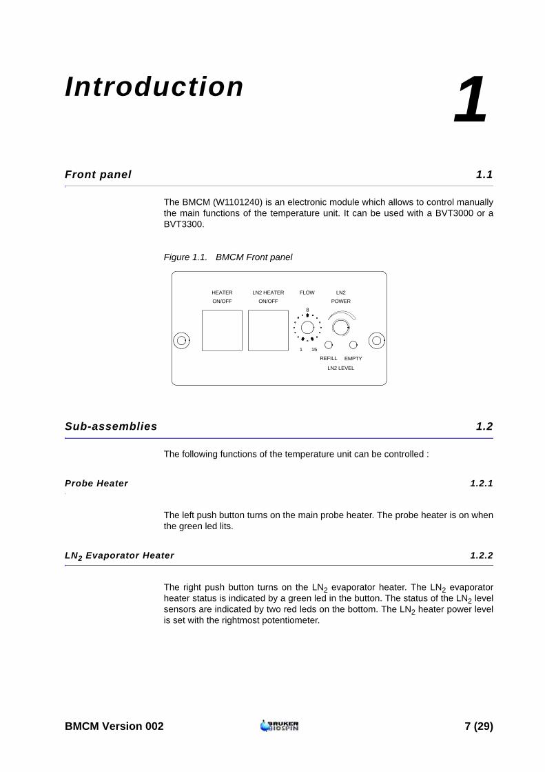
The BMCM (W1101240) is an electronic module which allows to control manually the main functions of the temperature unit. It can be used with a BVT3000 or a BVT3300.
Figure 1.1. BMCM Front panel
Sub-assemblies 1.2
The following functions of the temperature unit can be controlled :
Probe Heater 1.2.1
The left push button turns on the main probe heater. The probe heater is on when the green led lits.
LN2 Evaporator Heater 1.2.2
The right push button turns on the LN2 evaporator heater. The LN2 evaporator heater status is indicated by a green led in the button. The status of the LN2 level sensors are indicated by two red leds on the bottom. The LN2 heater power level is set with the rightmost potentiometer.
LN2 HEATER
ON/OFF ON/OFF
HEATER
REFILL
LN2 LEVEL
EMPTY
1 15
8
POWER
FLOW LN2
BMCM Version 002 7 (29)

Introduction
Gas Flow Control 1.2.3
The knob «FLOW» selects manually stepwise the gas flow from 0 to 2000 l/h.
Table 1.1. Gas flow control
Knob position Liter/hour
0 0
1 135
2 270
3 400
4 535
5 670
6 800
7 935
8 1070
9 1200
10 1335
11 1470
12 1600
13 1735
14 1870
15 2000
8 (29) BMCM Version 002
2Requirements 2
Hardware 2.1
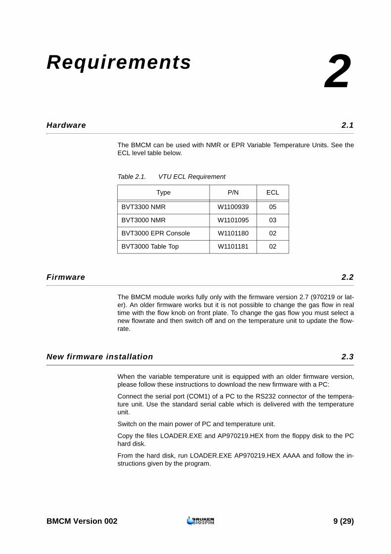
The BMCM can be used with NMR or EPR Variable Temperature Units. See the ECL level table below.
Table 2.1. VTU ECL Requirement
Firmware 2.2
The BMCM module works fully only with the firmware version 2.7 (970219 or lat-er). An older firmware works but it is not possible to change the gas flow in real time with the flow knob on front plate. To change the gas flow you must select a new flowrate and then switch off and on the temperature unit to update the flow-rate.
New firmware installation 2.3
When the variable temperature unit is equipped with an older firmware version, please follow these instructions to download the new firmware with a PC:
Connect the serial port (COM1) of a PC to the RS232 connector of the tempera-ture unit. Use the standard serial cable which is delivered with the temperature unit.
Switch on the main power of PC and temperature unit.
Copy the files LOADER.EXE and AP970219.HEX from the floppy disk to the PC hard disk.
From the hard disk, run LOADER.EXE AP970219.HEX AAAA and follow the in-structions given by the program.
Type P/N ECL
BVT3300 NMR W1100939 05
BVT3000 NMR W1101095 03
BVT3000 EPR Console W1101180 02
BVT3000 Table Top W1101181 02
BMCM Version 002 9 (29)
Requirements
10 (29) BMCM Version 002
3BMCM Module installation 3
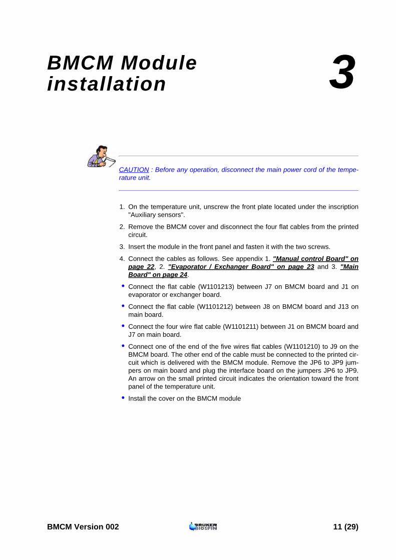
CAUTION : Before any operation, disconnect the main power cord of the tempe-rature unit.
1. On the temperature unit, unscrew the front plate located under the inscription "Auxiliary sensors".
2. Remove the BMCM cover and disconnect the four flat cables from the printed circuit.
3. Insert the module in the front panel and fasten it with the two screws.
4. Connect the cables as follows. See appendix 1. "Manual control Board" on page 22, 2. "Evaporator / Exchanger Board" on page 23 and 3. "Main Board" on page 24.
• Connect the flat cable (W1101213) between J7 on BMCM board and J1 on evaporator or exchanger board.
• Connect the flat cable (W1101212) between J8 on BMCM board and J13 on main board.
• Connect the four wire flat cable (W1101211) between J1 on BMCM board and J7 on main board.
• Connect one of the end of the five wires flat cables (W1101210) to J9 on the BMCM board. The other end of the cable must be connected to the printed cir-cuit which is delivered with the BMCM module. Remove the JP6 to JP9 jum-pers on main board and plug the interface board on the jumpers JP6 to JP9. An arrow on the small printed circuit indicates the orientation toward the front panel of the temperature unit.
• Install the cover on the BMCM module
BMCM Version 002 11 (29)
BMCM Module installation
12 (29) BMCM Version 002

4BVT3000 Temperature Controller Configuration 4
Sensor selection 4.1
The BVT3000 can be used with different temperature sensors :
• Thermocouple T, K or E
• BTO2000 (T thermocouple with external CJC at 0 C°)
• PT100
Warning: Never connect two sensors at a same time on the BVT3000.
Eurotherm 902 configuration 4.2
The EUROTHERM 902 controller must be configured to work with the right type of sensor.
The configuration is done with the Eurotherm 902 controller keypad (or by soft-ware in the EDTE program).
Proceed as follows :
1. Switch off the main power.
2. Press the two left most buttons : together while powering on the BVT3000.
3. The messages CONF and UCONF appear on the display.
4. Press the scroll button until ICONF is displayed.
BMCM Version 002 13 (29)
BVT3000 Temperature Controller Configuration
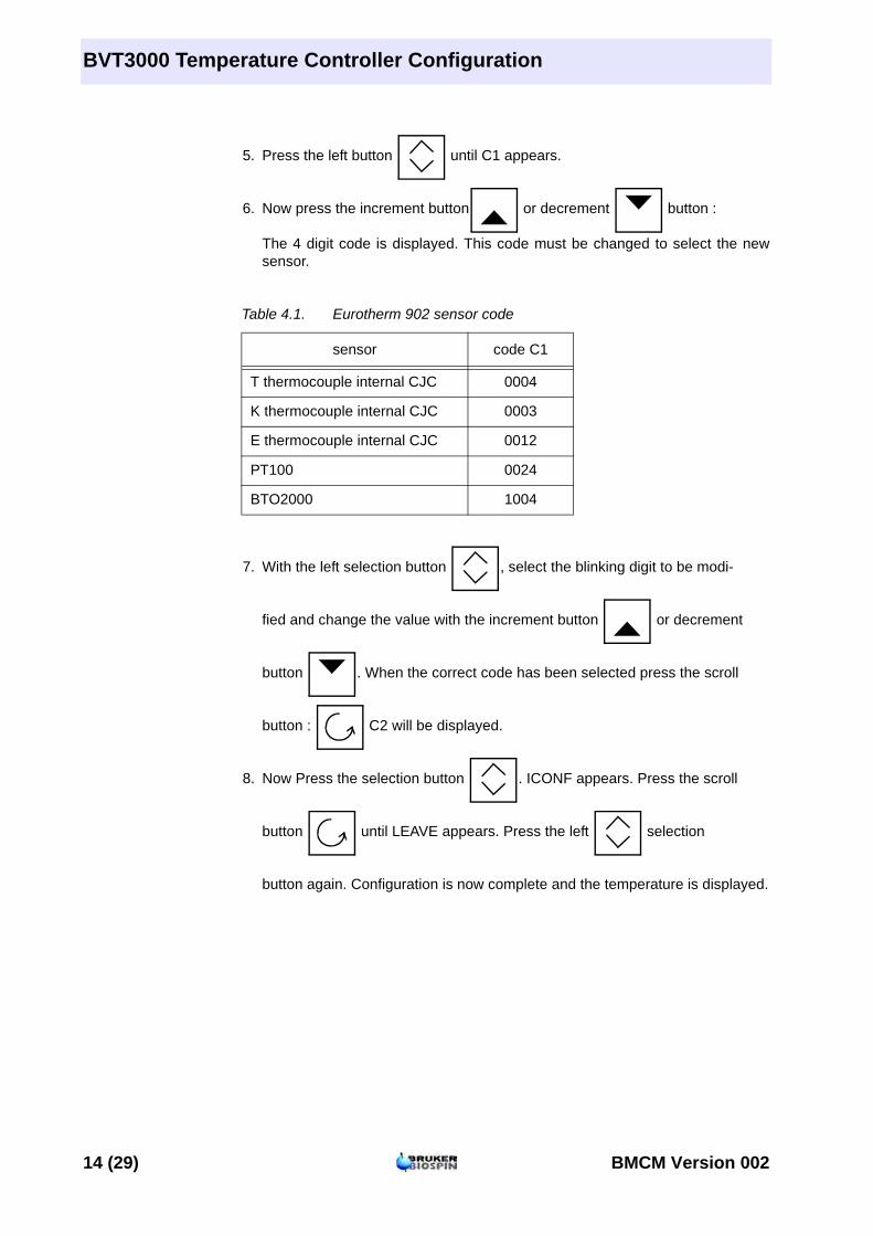
5. Press the left button until C1 appears.
6. Now press the increment button or decrement button : The 4 digit code is displayed. This code must be changed to select the new sensor.
Table 4.1. Eurotherm 902 sensor code
7. With the left selection button , select the blinking digit to be modi- fied and change the value with the increment button or decrement button . When the correct code has been selected press the scroll button : C2 will be displayed.
8. Now Press the selection button . ICONF appears. Press the scroll button until LEAVE appears. Press the left selection button again. Configuration is now complete and the temperature is displayed.
sensor code C1
T thermocouple internal CJC 0004
K thermocouple internal CJC 0003
E thermocouple internal CJC 0012
PT100 0024
BTO2000 1004
14 (29) BMCM Version 002
Parameter selection
Parameter selection 4.3
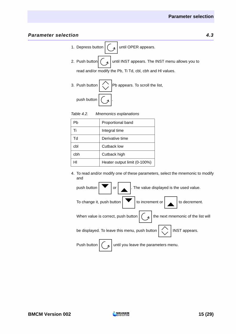
1. Depress button until OPER appears.
2. Push button until INST appears. The INST menu allows you to read and/or modify the Pb, Ti Td, cbl, cbh and Hl values.
3. Push button Pb appears. To scroll the list, push button .
Table 4.2. Mnemonics explanations
4. To read and/or modify one of these parameters, select the mnemonic to modify and push button or . The value displayed is the used value. To change it, push button to increment or to decrement. When value is correct, push button the next mnemonic of the list will be displayed. To leave this menu, push button INST appears. Push button until you leave the parameters menu.
Pb Proportional band
Ti Integral time
Td Derivative time
cbl Cutback low
cbh Cutback high
Hl Heater output limit (0-100%)
BMCM Version 002 15 (29)
BVT3000 Temperature Controller Configuration
Target Temperature Setting 4.4
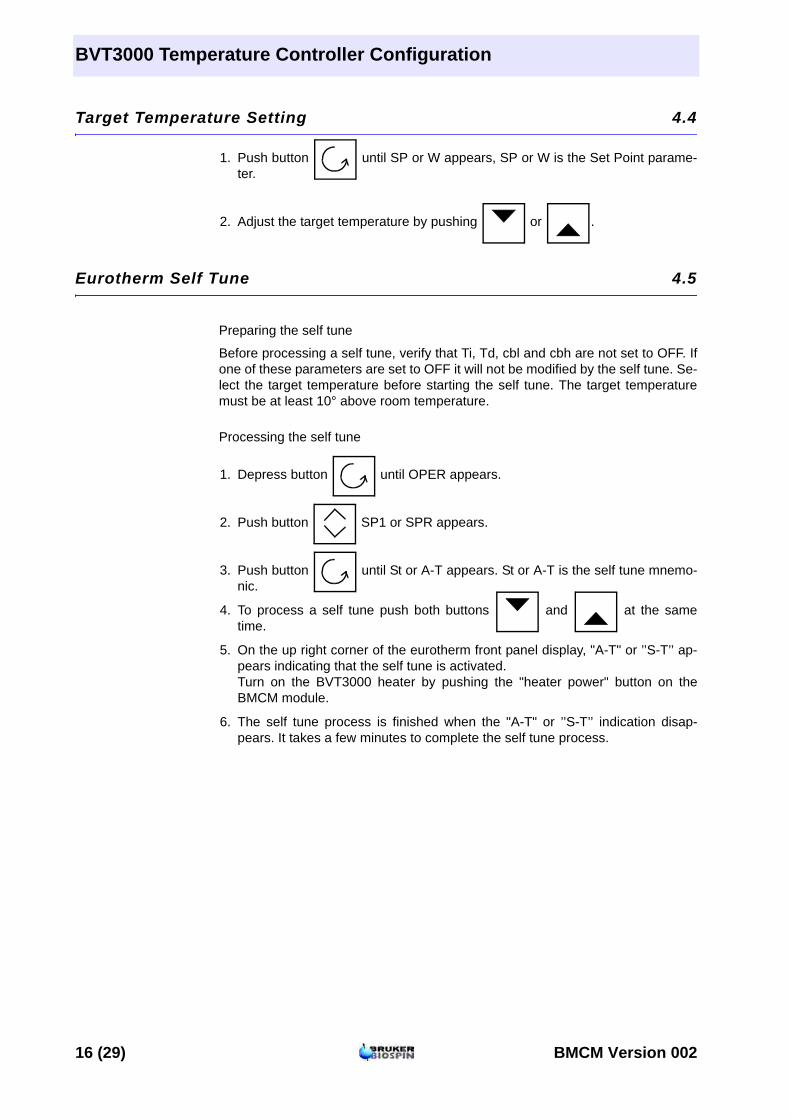
1. Push button until SP or W appears, SP or W is the Set Point parame-ter.
2. Adjust the target temperature by pushing or .
Eurotherm Self Tune 4.5
Preparing the self tune
Before processing a self tune, verify that Ti, Td, cbl and cbh are not set to OFF. If one of these parameters are set to OFF it will not be modified by the self tune. Se-lect the target temperature before starting the self tune. The target temperature must be at least 10° above room temperature.
Processing the self tune
1. Depress button until OPER appears.
2. Push button SP1 or SPR appears.
3. Push button until St or A-T appears. St or A-T is the self tune mnemo-nic.
4. To process a self tune push both buttons and at the same time.
5. On the up right corner of the eurotherm front panel display, "A-T" or ’’S-T’’ ap-pears indicating that the self tune is activated. Turn on the BVT3000 heater by pushing the "heater power" button on the BMCM module.
6. The self tune process is finished when the "A-T" or ’’S-T’’ indication disap-pears. It takes a few minutes to complete the self tune process.
16 (29) BMCM Version 002

5BVT3300 Temperature Controller Configuration 5
Sensor selection 5.1
The BVT3300 can be used with different types of sensors :
• Thermocouple T (factory set)
• BTO2000
• PT100 sensor
Warning : Never connect two sensors at a same time on the BVT3300.
Eurotherm 847 configuration 5.2
The EUROTHERM 847 controller must be configured to work with the right type of sensor.
To access the configuration mode, a switch located inside the 847 controller must be closed.
The switch must be closed only during the configuration mode.
Proceed as follows :
1. Switch off the main power.
2. Unscrew the EUROTHERM controller front plate.
3. Remove the module out of its cabinet.
4. The switch WB1 is located on the left side at the rear of the module.
5. Close the switch.
6. Insert the controller module and screw the front panel.
BMCM Version 002 17 (29)
BVT3300 Temperature Controller Configuration
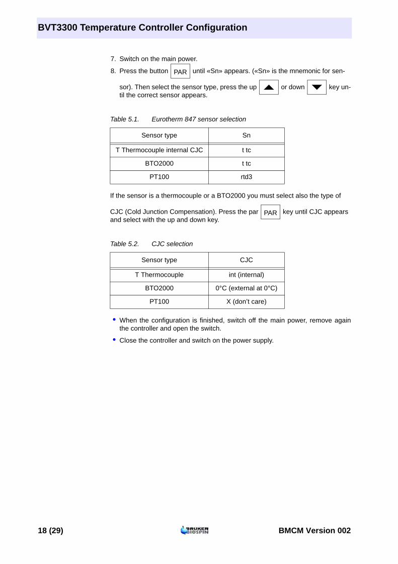
7. Switch on the main power.
8. Press the button until «Sn» appears. («Sn» is the mnemonic for sen- sor). Then select the sensor type, press the up or down key un-til the correct sensor appears.
Table 5.1. Eurotherm 847 sensor selection
If the sensor is a thermocouple or a BTO2000 you must select also the type of CJC (Cold Junction Compensation). Press the par key until CJC appears and select with the up and down key.
Table 5.2. CJC selection
• When the configuration is finished, switch off the main power, remove again the controller and open the switch.
• Close the controller and switch on the power supply.
Sensor type Sn
T Thermocouple internal CJC t tc
BTO2000 t tc
PT100 rtd3
Sensor type CJC
T Thermocouple int (internal)
BTO2000 0°C (external at 0°C)
PT100 X (don’t care)
PAR
PAR
18 (29) BMCM Version 002

Parameter selection
Parameter selection 5.3
To access the configuration mode, a switch located inside the 847 controller must be closed (see previous section).
We suppose that the internal switch is closed.
1. Pushing the button allows the user to scroll through parameters. Only six of them can be modified by the user. Modifying one of the other breaks the factory warranty.
2. The parameters the user is allowed to change are the following :
ProP Proportional band Int.t Integral time dEr.t Derivative time H PL Heater output limit (0 to 100%) Sn Sensor type CJC Cold junction compensation
3. Press button until the parameter to be modified appears. To chose a new type of sensor, CJC or to modify the value of the parameter press button
or . When the value is correct push button until the measured temperature appears.
4. Open the internal switch as explained in the previous section.
Self tune 5.4
1. Before starting a self tune, please verify that parameters Prop, Int.t, and dEr.t are not equal to 0. Also verify that H PL contents the correct value.
2. Push button until «tune» appears.
3. To start a self tune, push button or and then, switch on the hea-ter power.
Target temperature selection 5.5
The lower part of the display shows the selected target temperature. Target temperature can be modified by pushing button or .
PAR
PAR
PAR
PAR
BMCM Version 002 19 (29)

BVT3300 Temperature Controller Configuration
20 (29) BMCM Version 002

6Appendix 6
BMCM Version 002 21 (29)
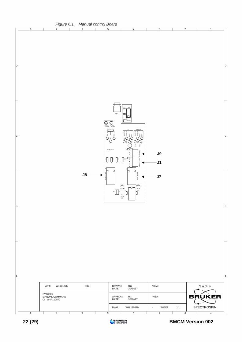
Figure 6.1. Manual control Board
8 7 6 5 4 3 2 1
A
B
C
D
12345678
D
C
B
A
BVT3X00
ART: W1101235 EC: DRAWN:DATE:
APPROV:DATE:
DWG:
RC30/04/97
W4L110570
RC30/04/97
VISA:
VISA:
SHEET: 1/1
S.a.d.i.s
SPECTROSPIN
MANUAL COMMAND
-
TO
MA
IN B
RD
TO
EV
AP
BR
D
FL
OW
AD
PT
HE
AT
ER
CM
DL
ED
+
LE
D-
LE
D+
LE
D-
SW
ITC
H
SW
ITC
H
SW
ITC
H
SW
ITC
H
HEATERLN2LN2 POWER
REFILLEMPTYK K
FRONT
J12
J11
W4P110570
SW1
J10
TP
11
TP
12
TP
13
TP
14
TP
21
TP
22
TP
23
TP
24
TP
51
TP
52
TP
53
R6 R5R4 R3
R2 R1
C5
U1
C4C3
C1 C2
J9
J1
J7J8
LD2LD1
J9
J1
J7J8
CI : W4P110570
22 (29) BMCM Version 002

Figure 6.2. Evaporator / Exchanger Board
8 7 6 5 4 3 2 1
A
B
C
D
12345678
D
C
B
A
BDTC
ART: W1100957 or W1101049 EC: DRAWN:DATE:
APPROV:DATE:
DWG:
RC22/09/94
W4L10295
RC22/09/94
VISA:
VISA:
SHEET: 1/1
S.a.d.i.s
SPECTROSPIN
EVAPORATOR / EXCHANGERCI : W4P10295D
D
BDTC EVAPORATOR
W4P10295D
+15V
GN
D
-15V
HRLYEMPTY
P_EMPTY
P_REFL
N2 L
VL
AC
PO
WE
R IN
PU
T
220V AC
DA
C
REFILL
Exch
Evap
D_EMPTY
6.3A
1A
EXCHANGER
T2
RL1
F1
F2
U4
U5 U2U6
U1
U3
D4
D5
ZD
1
ZD2
ZD5
ZD3
D8
D6
ZD7D3
ZD6
D2
D7
C15
C6
C2
C1
C11
C16C13
C12
C19
C7
C17 C14 C10
C3
C5C9
J4
J1
R27
R34
R20R19R26
R25
R29
R32
R6
R28R23
R31
R7
R21
R18
R11
R13
R12
R22
R14
R1
R2
R9R10
R15
R16
R17
R24
R30
R4R5
R8
R33
J6
RN
3
RN
2
RN
1
J3J5
T1
TR
1
TP
1T
P2
TP
3
TP4
TP
5
TP7
TP8
TP9
TP10
TP11TP12
C18
C20
C8U7
J1
BMCM Version 002 23 (29)
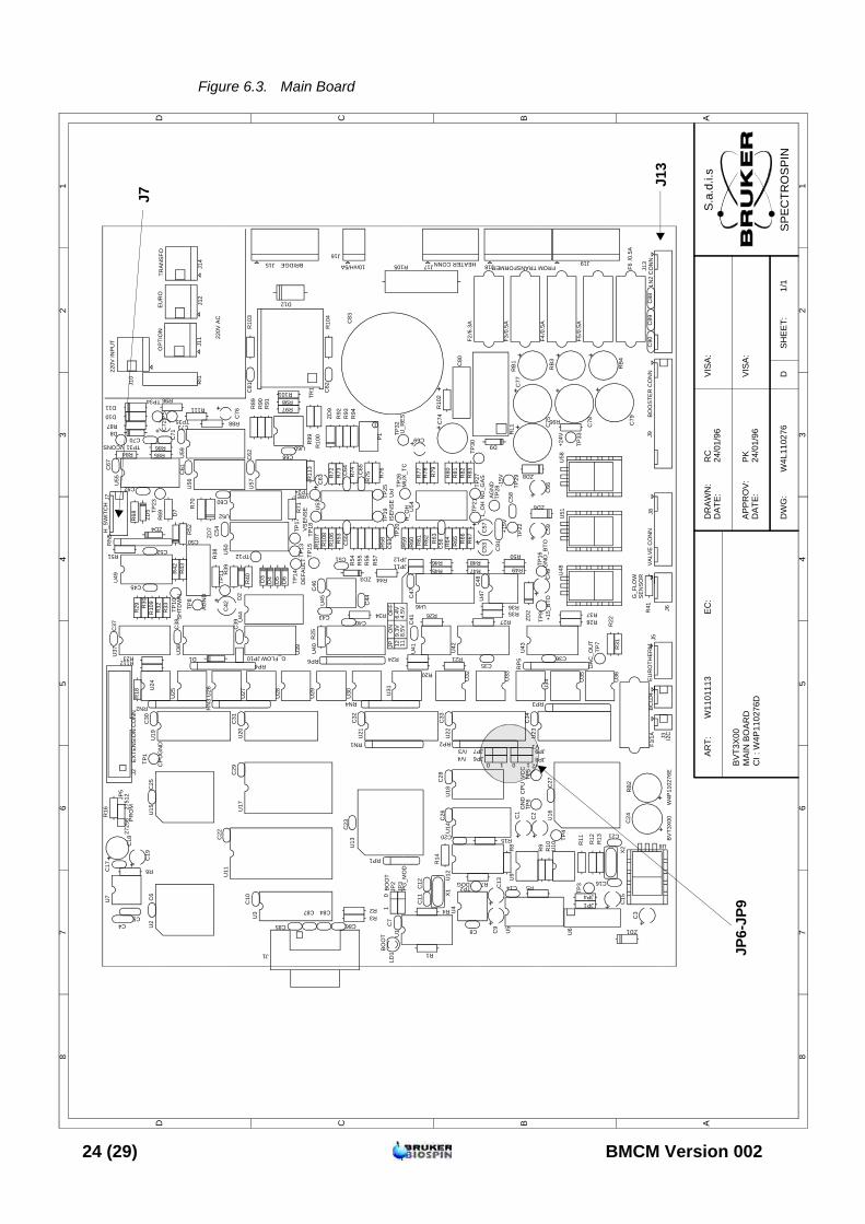
Figure 6.3. Main Board
87
65
43
21
ABCD
12
34
56
78
D C B AA
RT
:
BV
T3X
00
W11
0111
3D
RA
WN
:D
AT
E:
AP
PR
OV
:D
AT
E:
DW
G:
EC
:V
ISA
:
VIS
A:
RC
24/0
1/96
W4L
1102
76
24/0
1/96
PK
DS
HE
ET
:1/
1
S.a
.d.i.
s
SP
EC
TR
OS
PIN
MA
IN B
OA
RD
CI :
W4P
1102
76D
220V
AC
FROM TRANSFORMER
/0.5
A
/6.3
A
/0.5
A
/0.5
A
/1A
GN
DV
CC
+15V
AG
ND -1
5V
+24V
BRIDGE 10mH/5A HEATER CONN
EU
RO
THE
RM
VS
EN
SE
ISEN
SE
UxI
H_O
H
L_O
HN
O_G
AS
G_FLOW
G_F
LOW
SE
NS
OR
VA
LVE
CO
NN
EX
TEN
SIO
N C
ON
N
LN2
CO
NN
BV
T3X
00W
4P11
0276
E
TRA
NSF
OE
UR
OO
PTI
ON
220V
INP
UT
CP
U
CP
UG
ND
U_R
ES
VCONS
AG
ND
DA
C_O
UT
+15_
BTO
GN
D_B
TO
SH
TDW
N
PS
VREF
MU
X_T
C
DE
FAU
LT
DOG
/0.5
A
BO
OS
TER
CO
NN
I2C
BC
U
/V4/V3
V2
V1
0 1 0 1
BO
OT
10
PG
_MO
D
2725
627
512
PR
OM
BO
OT
ON
OFF
JP
H_S
WIT
CH
129.
3V6.
4V11
8.5V
4.5V
J15 J18 J19
J13
J8
J6
J17
U13
U16
U20
U19 U21
U23
U3
U22
U15
U2
U11
U4
U25 U26
U27
U28
U29
U30 U31
U32
U33
U34 U
35
U36
U45
U41
U60
U24
U7
U47
U14
U5
U44
U40
U55
U50
U59
U46
U18
U12
U38
U39 U42
U43
U54U53
U49
U57
U37
U56
U52
U1
U10
U9
F1
F3 F4 F5F2
F6R
B2
RB
1
RB
3
RB
4
C77
C75
C78 C79
U8
U51
U48
ZD1
ZD6
ZD8
D10D11
ZD9
ZD7
ZD2
JP1JP4
R95
R10
4
R96
R10
3
R10
2
R86
R87
R51
R43
R42
R33
R32
R31
R29 R
30
R22
R75
R53
R54
R55
R56
R57
R58
R74
R93
R94
R76
R97R98R101
R91
R90
R99
R10
0
R79
R78
R77
R92
R80
R62 R63
R59 R64 R
66R
65 R67
R81
R82
R83
R41
R70
R40
R39
R28R37R26
R20
R27
R5
R9
R8
R10 R
11R15
R13
R12
R14
R25
R34
R72
R73
R85R84
R24 R21
R44
R88
R38
R7
R60
R46R45 R47
R50
R49
R36R35
R48
R18
R23
R6
R1
R16
R89
R61
R2R3
R71
R52
R4
R69
R68
R10
8R
107
R10
6
R111
R112
R10
9
R11
3
U58
U6
D12
C82
C81
C71C70
C65C
67
C68
C55
C64
C45
C52
C14
C21
C16
C27
C11
C12
C30 C32
C43
C46
C40
C39
C34
C23
C28
C26
C29
C7
C31
C20
C8
C44
C58
C54
C38
C36C35
C41
C56
C60
C62
C37
C73
C61
C51
C17
C25
C47
C33
C48
C10C
6
C22
C87
C86C85
C84
C92
C93
RL1
C80
C15
C9
C1
C2
C13
C3
C49
C53
C57
C59
C66
C19
D8
ZD4
D1
D4D3
D6
D5
D2
ZD3
D9
D7
ZD5
C50
P1
C74
C24
JP10
JP12JP11
RI1
U17
C76
C63
C69
C72
J16
RP6RP4
RP
5RP3
RP2
RN
5
RN4
RN1
RN
3
RN2
J5
C42
J10
J11
J12
J14 R105
C83
J9
J7
J4
J3
JP6JP7
JP8JP9
JP5
JP3
JP2
C4C5
C91
C90
C89
C88
C18
LD1
RP1
J2
X1
X2
TR1
J1
TP1
TP2
TP3
TP4
TP5
TP6
TP7
TP8
TP9TP
10
TP11
TP12 TP13
TP14
TP15
TP16
TP17
TP18
TP19
TP20
TP21
TP22
TP23
TP24
TP25 TP
26
TP27
TP28 TP
29
TP30TP31
TP32
TP33
TP34
TP35
J7
JP6-
JP9
J13
24 (29) BMCM Version 002

Figures
1 Introduction 7Figure 1.1. BMCM Front panel ............................................................... 7
2 Requirements 9
3 BMCM Module installation 11
4 BVT3000 Temperature Controller Configuration 13
5 BVT3300 Temperature Controller Configuration 17
6 Appendix 21Figure 6.1. Manual control Board ......................................................... 22Figure 6.2. Evaporator / Exchanger Board ............................................ 23Figure 6.3. Main Board ......................................................................... 24
BMCM Version 002 25 (29)
Figures
26 (29) BMCM Version 002
Tables
1 Introduction 7Table 1.1. Gas flow control ............................................................... 8
2 Requirements 9Table 2.1. VTU ECL Requirement .................................................... 9
3 BMCM Module installation 11
4 BVT3000 Temperature Controller Configuration 13Table 4.1. Eurotherm 902 sensor code ........................................... 14Table 4.2. Mnemonics explanations ................................................ 15
5 BVT3300 Temperature Controller Configuration 17Table 5.1. Eurotherm 847 sensor selection ..................................... 18Table 5.2. CJC selection ................................................................ 18
6 Appendix 21
BMCM Version 002 27 (29)

Tables
28 (29) BMCM Version 002
Notes
BMCM Version 002 29 (29)
Lastpage