2016 edition - racing beat · racing beat has devoted more than 40 years to the research,...
TRANSCRIPT
2016 Edition

From its inception in 1971, Racing Beat, Inc. has been involved in a variety of racing, engine, and project car programs.
®
1971 Racing Beat founded1972 Midget fuel injected race engines – won numerous races before being outlawed. 1973 Car and Driver RX-2 IMSA R/S engines – won (2) races and (1) second place in (5)
starts. 1974 Mechanically supercharged street engine developed.1974 Turbocharged aircraft engines – 300 HP @ 8400 RPM.1974 Car and Driver RX-3 Bonneville Salt Flats engines – boosted class production record
from 139.1 to 160.3 MPH. 1977 NHRA RX-3 drag race project car – class record holder for 1977-78 – won Modified
Eliminator in 1978.1978 Bonneville Salt Flats RX-7 – boosted E/GT record from 167.208 to 183.904 MPH.1980 IMSA GTU RX-7 road race project cars – 1st and 2nd place in 1980 IMSA Championship.
Eight class victories.1982 NASA single rotor engines – built for NASA research. 1983 IMSA GTO RX-7 race car – won Daytona 24-hour and Mosport 6-hour races. 1984 BF Goodrich IMSA GTP/Group C engines – Jim Russell Mazda Pro-Series engines
– development of Dell’Orto 48 DHLA sidedraft intake systems. 1985 Four rotor engine – 600+ HP / 350 ft-lbs of torque at 9000 rpm. Rotary engines devel-
oped for Mazda trucks racing in the Mickey Thompson Off-Road Series. 1986 Bonneville Salt Flats RX-7 – boosted Class C/GT record from 201.241 to 238.442 MPH. 1987 RX-7 Roadster project – cover story in Car and Driver Magazine. 1990 “California Haulin’” rotary-powered pickup truck, featured in Hot Rod Magazine and
Truckin’ Magazine – Miata “Style and Sports” components line developed. 1991 Engineered turbocharged self-contained industrial engines for worldwide remote-drop
seismic drilling. 1992 Bonneville Salt Flats RX-7 – engineered 3-turbo, 3-rotor, 13G engines producing 944 HP
@ 8700 RPM. 1993 Racing Beat Miata sets MOTOR TREND Magazine record – 73.6 MPH in slalom testing. 1994 Bonneville Salt Flats RX-7 prepared race car sets El Mirage Dry Lake record – 204+ MPH,
during development testing. 1995 Bonneville Salt Flats RX-7 race car sets C/BMS class record of 242.005 MPH at
Bonneville Nationals Event. 1996 Introduced RS*R High Performance Exhaust Systems to the US market for a wide selec-
tion of performance oriented automobiles.1998 Engineered 3-rotor, single turbo drag racing engine producing 820 HP @ 8700 RPM. -
Developed performance products for 2nd generation Miata.1999 Developed 3-rotor, single turbo aviation engine producing 900 HP @ 6750 RPM. 2000 Racing Beat Miata sets Sport Compact Car Magazine performance records - 1.1g in skid-
pad, 70.6 MPH slalom2001 Participated in the development of the Mazda Protege MP3 with Mazda North American
Operations. 2002 Continued development with Mazda on the MazdaSpeed Protege. Provided exhaust
components for production cars.2003-04 Undertook extensive product development for the Mazda RX-8. Continued R&D work for
Mazda North America.2005 Began development of products for Mazda3, Mazda6, MX-5 applications.
2015 Participated with University of California, Irvine on a enery recovery natural-gas powered Renesis engine program. NHRA RX-3 Drag Race Car
Car and Driver Bonneville Project
Car and Driver RX-2 IMSA R/S
3
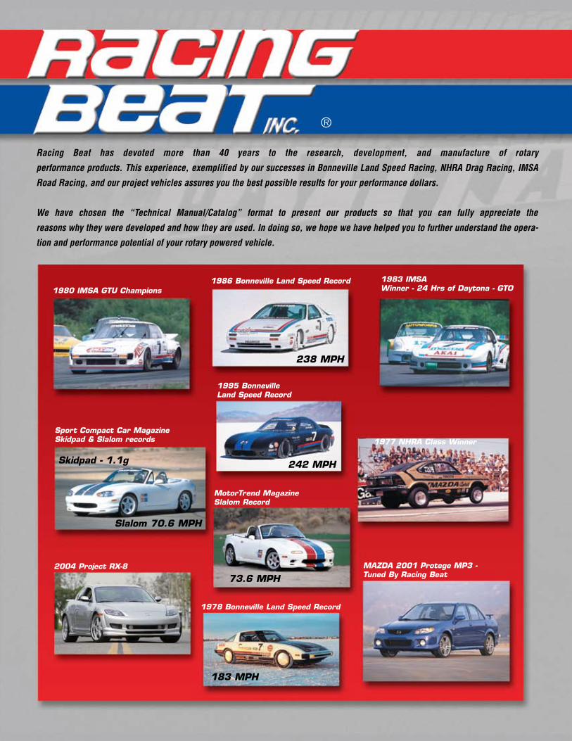
Racing Beat has devoted more than 40 years to the research, development, and manufacture of rotary
performance products. This experience, exemplified by our successes in Bonneville Land Speed Racing, NHRA Drag Racing, IMSA
Road Racing, and our project vehicles assures you the best possible results for your performance dollars.
We have chosen the “Technical Manual/Catalog” format to present our products so that you can fully appreciate the
reasons why they were developed and how they are used. In doing so, we hope we have helped you to further understand the opera-
tion and performance potential of your rotary powered vehicle.
1980 IMSA GTU Champions1986 Bonneville Land Speed Record 1983 IMSA
Winner - 24 Hrs of Daytona - GTO
1995 Bonneville Land Speed Record
MAZDA 2001 Protege MP3 - Tuned By Racing Beat
1977 NHRA Class WinnerSport Compact Car Magazine Skidpad & Slalom records
Skidpad - 1.1g
Slalom 70.6 MPH
73.6 MPH
1978 Bonneville Land Speed Record
2004 Project RX-8
MotorTrend Magazine Slalom Record
238 MPH
242 MPH
183 MPH
®

4 www.racingbeat.com
ONE YEAR LIMITED WARRANTY: For one year from original purchase, subject to limitations following, genu-ine Racing Beat, Inc. (“Racing Beat ®”) manufactured* products (“Products”) are warranted to be free from material or workmanship defects. This warranty is valid only for original retail purchasers (Buyer) and is not transferable. Keep your original sales receipt; proof-of-purchase and retail price paid is required. Altered, abused, negligently damaged or incorrectly installed products are not warranted. Similarly, the warranty does not extend to normal wear and tear.
Racing Beat’s® sole obligation under this warranty shall be to repair or replace any defective Products, or to refund the original retail purchase price paid by the Buyer (not including sales tax, freight or handling charges) at Racing Beat’s® sole, absolute and unrestricted discretion. Cost of painting services, installation, removal and re-installation charges are not included as part of this limited warranty. Buyer assumes sole and complete responsibility for such painting services, installation, removal and/or re-installation.
To submit a warranty claim, Buyer must contact Racing Beat® to obtain a Return Authorization Number and shipping instructions. Products returned to Racing Beat® must be shipped at Buyer’s expense. Buyer shall be solely responsible for proper packaging and shipment insurance.
Effective as of 05/1/2016.
RACING BEAT® DISCLAIMS ANY WARRANTIES, EXPRESS OR IMPLIED, INCLUDING, WITHOUT LIMITATION,
THE IMPLIED WARRANTIES OF MERCHANTABILITY OR FITNESS FOR A PARTICULAR USE OR PURPOSE EXCEPT AS EXPRESSLY SET FORTH HEREIN. SIMILARLY, OTHER THAN THE EXCLUSIVE REPAIR, REPLACE OR REFUND REMEDIES SET FORTH ABOVE, RACING BEAT® DISCLAIMS, AND SHALL NOT RE RESPONSIBLE FOR, ANY OTHER GENERAL, SPECIAL, DIRECT, INDIRECT, OR CONSEQUENTIAL DAMAGES CAUSED BY ANY ACTUAL OR ALLEGED DEFECT IN RACING BEAT’S® PRODUCTS OR AS A RESULT OF ANY BREACH OF PROMISE OR WARRANTY BY RACING BEAT.
This warranty gives you specific legal rights, and you may have other rights that vary from state to state.
*Products manufactured by others and resold through Racing Beat® (“Third Party OEM Products”) are not covered under this warranty. RACING BEAT EXPRESSLY DISCLAIMS ANY WARRANTIES, EXPRESS OR IMPLIED, INCLUDING, WITHOUT LIMITATION, THE IMPLIED WARRANTIES OF MERCHANTABILITY OR FITNESS FOR A PARTICULAR USE OR PURPOSE WITH RESPECT TO THIRD PARTY OEM PRODUCTS. RACING BEAT® FURTHER DISCLAIMS, AND SHALL NOT BE RESPONSIBLE FOR , AND GENERAL, DIRECT, INDIRECT OR CONSEQUENTIAL DAMAGES CAUSED BY ANY ACTUAL OR ALLEGED DEFECT IN THIRD PARTY OEM PRODUCTS. The only warrant(ies) applicable to Third Part OEM Products are those offered by the actual manufacturers of such products.
BUSINESS HOURS - M-F, 8:00-5:00 PM Pacific Time
RETAIL COUNTER - 4789 E Wesley Drive, Anaheim, CA 92807 714-779-8677 • FAX 779-2902
Email us at: [email protected]
PRICING - Although our price list is updated as often as practical, prices are subject to change without notice. Please contact our Sales Representatives to confirm current pricing.
SALES TAX - California residents will be assessed the prevailing sales tax rate for Orange County, California.
ORDERING - Orders can be placed by mail, fax, internet, or by contacting Racing Beat. When placing your order by mail or fax, please provide all neces-sary information: i.e., chassis year/chassis model/engine type/engine year/modifications, etc. By pro-viding this information, we can serve you more effi-ciently.
TERMS - We accept MasterCard, VISA, Discover and American Express with a $25 minimum order.* We must ship all credit card orders to the billing address for that particular credit card. For direct payment, we recommend a Certified Check, or Cashier’s Check with your mail order. Both personal and business checks require a three week waiting period from the date we DEPOSIT your check until the parts are shipped from our facility, thereby allowing for inter-bank, Federal Reserve, and postal transit time.
SHIPPING - We utilize United Parcel Service (UPS). as our standard freight carrier. UPS will deliver only to street addresses, not P. O. boxes. Please contact us concerning shipments requiring truck or air freight, and shipment via U.S. Postal Service.
PACKAGING & HANDLING CHARGE - A nominal fee of $2.00 per $100.00 of product ordered is charged for packaging and handling.
$ Value of order For example: $ 1-100=$2.00 Charge $101-200=$4.00 Charge $201-300=$6.00 Charge
INTERNATIONAL ORDERS - All international orders require pre-payment in full for merchandise and freight. Due to our bank’s credit card policy, we are unable to accept credit cards for international orders.
All customs duties, tariffs, and other fees are the sole responsibility of the consignee. To obtain a price quote including shipping, contact us directly.
UNITED PARCEL SERVICE (UPS) ships to virtually all international locations. If you require another method of transportation, YOU must make arrange-ments with your freight forwarder and provide us with the local contact person’s name, phone number, and address to ship the parts. Contact us for more details.
RETURNS - Authorization from Racing Beat, Inc. and a RETURN AUTHORIZATION NUMBER must be obtained before returning any merchandise, or the package will be refused. This includes mis-ship-ments! A 20% re-stocking charge or a flat $25.00 fee (whichever is greater) is normally assessed on returns due to customer error. Refunds will not be issued if merchandise has been damaged in han-dling, return transit, modified, painted, or used. Apex seal, spark plugs, ring & pinion gears,and stationary gears cannot be returned for exchange or refund due to their fragile nature and possible customer mishandling.
CANCELLATIONS/ REFUSED SHIPMENTS/ ORDERS Orders cancelled at the customer’s request are sub-ject to charges equal to the costs incurred by Racing Beat, Inc., at the time of cancellation. Shipments returned by a freight carrier as “undeliverable” – refused, non-payment, not in on three delivery attempts, etc. – will result in the customer’s account being “frozen” until all charges due Racing Beat, Inc. are paid in full. Parts that are “Special Order” items – items not normally stocked by Racing Beat, Inc. – and parts left with Racing Beat, Inc. for modification require a 100% non-refundable deposit at the time the order is placed.
SHORTAGE/ DAMAGE/ ERROR - Inspect all mer-chandise and verify to the invoice immediately upon receipt. Shortage / damage / error claims must be made within 5 business days. If parts are damaged, save the original shipping cartons and all packing materials to allow for freight carrier inspection or the claim cannot be honored.
PRODUCT DESCRIPTIONS - Actual products may differ in appearance from those shown.
Copyright © 2016 Racing Beat, LLCNo part of this publication may be reproduced, stored in a retrieval system or transmitted in any form or by any means, electronic, photocopying or otherwise, without prior written permission of Racing Beat. All rights reserved.
Sales Policies
Sales Policies . . . . . . 4
Intake . . . . . . . . . . . . 6
Exhaust . . . . . . . . . . 16
Rebuild Kits/ Manuals/ Seatcovers . . . . . . . 29
Ignition . . . . . . . . . . 30
Engine . . . . . . . . . . 34
Engine Services . . . . 46
Water Cooling . . . . . 48
Engine - Oil Cooling & Lubrication . . . . . . . 51
Drive Line . . . . . . . . 57
Suspension . . . . . . . 67
Brakes . . . . . . . . . . 75
Body Kits . . . . . . . . . 76
Accessories & Apparel . . . . . . . . . . 78
Table of Contents
* Technical Catalogs Exception.
For orders shipped to or within the USA, Canada, & Puerto Rico, we accept:
Racing Beat’s One Year Limited Warranty
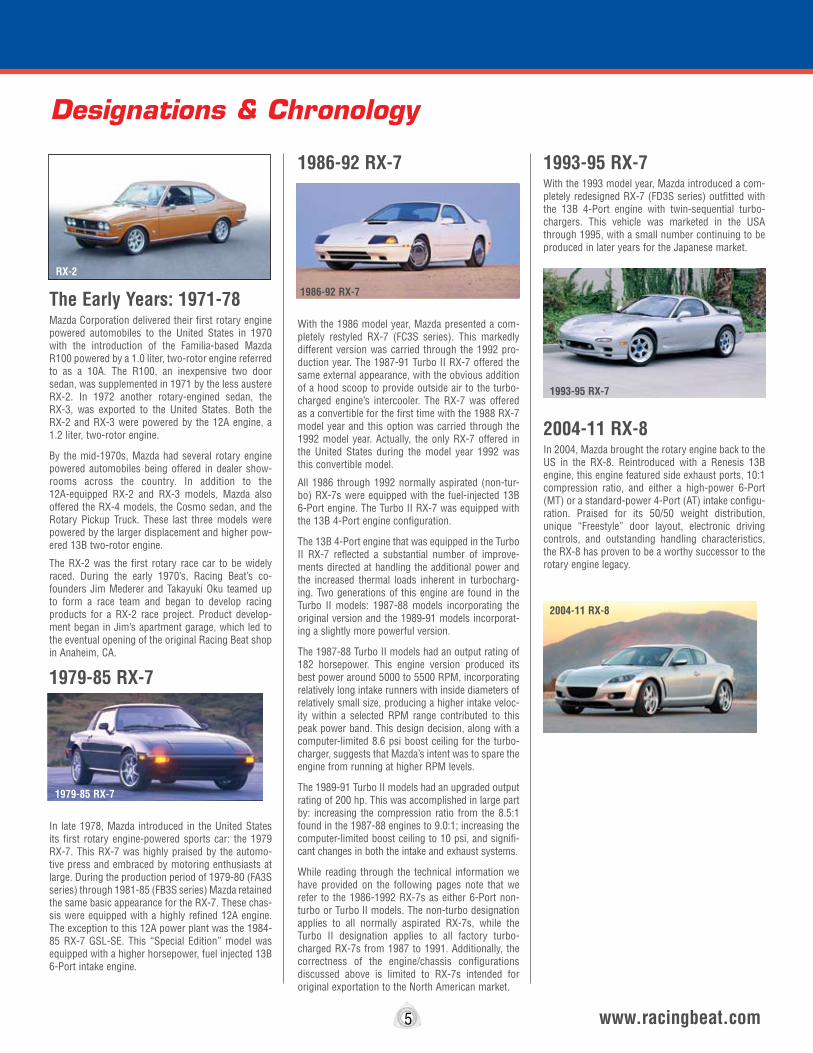
The Early Years: 1971-78 Mazda Corporation delivered their first rotary engine powered automobiles to the United States in 1970 with the introduction of the Familia-based Mazda R100 powered by a 1.0 liter, two-rotor engine referred to as a 10A. The R100, an inexpensive two door sedan, was supplemented in 1971 by the less austere RX-2. In 1972 another rotary-engined sedan, the RX-3, was exported to the United States. Both the RX-2 and RX-3 were powered by the 12A engine, a 1.2 liter, two-rotor engine.
By the mid-1970s, Mazda had several rotary engine powered automobiles being offered in dealer show-rooms across the country. In addition to the 12A-equipped RX-2 and RX-3 models, Mazda also offered the RX-4 models, the Cosmo sedan, and the Rotary Pickup Truck. These last three models were powered by the larger displacement and higher pow-ered 13B two-rotor engine.
The RX-2 was the first rotary race car to be widely raced. During the early 1970’s, Racing Beat’s co-founders Jim Mederer and Takayuki Oku teamed up to form a race team and began to develop racing products for a RX-2 race project. Product develop-ment began in Jim’s apartment garage, which led to the eventual opening of the original Racing Beat shop in Anaheim, CA.
1979-85 RX-7
In late 1978, Mazda introduced in the United States its first rotary engine-powered sports car: the 1979 RX-7. This RX-7 was highly praised by the automo-tive press and embraced by motoring enthusiasts at large. During the production period of 1979-80 (FA3S series) through 1981-85 (FB3S series) Mazda retained the same basic appearance for the RX-7. These chas-sis were equipped with a highly refined 12A engine. The exception to this 12A power plant was the 1984-85 RX-7 GSL-SE. This “Special Edition” model was equipped with a higher horsepower, fuel injected 13B 6-Port intake engine.
1986-92 RX-7
With the 1986 model year, Mazda presented a com-pletely restyled RX-7 (FC3S series). This markedly different version was carried through the 1992 pro-duction year. The 1987-91 Turbo II RX-7 offered the same external appearance, with the obvious addition of a hood scoop to provide outside air to the turbo-charged engine’s intercooler. The RX-7 was offered as a convertible for the first time with the 1988 RX-7 model year and this option was carried through the 1992 model year. Actually, the only RX-7 offered in the United States during the model year 1992 was this convertible model.
All 1986 through 1992 normally aspirated (non-tur-bo) RX-7s were equipped with the fuel-injected 13B 6-Port engine. The Turbo II RX-7 was equipped with the 13B 4-Port engine configuration.
The 13B 4-Port engine that was equipped in the Turbo II RX-7 reflected a substantial number of improve-ments directed at handling the additional power and the increased thermal loads inherent in turbocharg-ing. Two generations of this engine are found in the Turbo II models: 1987-88 models incorporating the original version and the 1989-91 models incorporat-ing a slightly more powerful version.
The 1987-88 Turbo II models had an output rating of 182 horsepower. This engine version produced its best power around 5000 to 5500 RPM, incorporating relatively long intake runners with inside diameters of relatively small size, producing a higher intake veloc-ity within a selected RPM range contributed to this peak power band. This design decision, along with a computer-limited 8.6 psi boost ceiling for the turbo-charger, suggests that Mazda’s intent was to spare the engine from running at higher RPM levels.
The 1989-91 Turbo II models had an upgraded output rating of 200 hp. This was accomplished in large part by: increasing the compression ratio from the 8.5:1 found in the 1987-88 engines to 9.0:1; increasing the computer-limited boost ceiling to 10 psi, and signifi-cant changes in both the intake and exhaust systems.
While reading through the technical information we have provided on the following pages note that we refer to the 1986-1992 RX-7s as either 6-Port non-turbo or Turbo lI models. The non-turbo designation applies to all normally aspirated RX-7s, while the Turbo II designation applies to all factory turbo-charged RX-7s from 1987 to 1991. Additionally, the correctness of the engine/chassis configurations discussed above is limited to RX-7s intended for original exportation to the North American market.
1993-95 RX-7With the 1993 model year, Mazda introduced a com-pletely redesigned RX-7 (FD3S series) outfitted with the 13B 4-Port engine with twin-sequential turbo-chargers. This vehicle was marketed in the USA through 1995, with a small number continuing to be produced in later years for the Japanese market.
2004-11 RX-8In 2004, Mazda brought the rotary engine back to the US in the RX-8. Reintroduced with a Renesis 13B engine, this engine featured side exhaust ports, 10:1 compression ratio, and either a high-power 6-Port (MT) or a standard-power 4-Port (AT) intake configu-ration. Praised for its 50/50 weight distribution, unique “Freestyle” door layout, electronic driving controls, and outstanding handling characteristics, the RX-8 has proven to be a worthy successor to the rotary engine legacy.
5 www.racingbeat.com
Designations & Chronology
1986-92 RX-7
1979-85 RX-7
1993-95 RX-7
RX-2
2004-11 RX-8

Carbureted Engine TipsCarburetion is a very complex subject, and any dis-cussion here can only deal with generalities. It is also an important subject, since performance, economy, and smoothness are all very much affected by carbure-tion.
Stock CarburetorsThe stock carburetors on Mazda rotaries are excellent parts, well designed and well built. The only problem is that, for most performance work, they are too small. This shortcoming can be partly offset by increasing the size of the venturis; however, other problems arise in lower RPM street use, such as poor mixture, spark plug fouling, poor throttle response, and poor mileage. Therefore, even though it is pos-sible to improve power using the stock carburetor, we do not recommend it for street use.
Regarding the emission controls that are installed on and around the carburetor: In our experience, the only reason for removing them is simplicity, and the reliability this simplification offers. Neither the valves nor the air pump, if operating properly, has a signifi-cant effect on mileage or performance. Many of these parts operate only on deceleration or when the engine is shut off. If you decide that, for simplicity, you wish to remove the air valves and the air pump, we recom-mend the following:
On 1975 and earlier 12A engines, either replace the stock air nozzles with our Blocking Nozzles (See page 44) or cut off the top .125-inch of the stock air noz-zles, weld the end shut, and re-install them. On all models, retain the fuel tank vent hose (on most models, it enters the top of the air cleaner) as well as some form of crankcase breather from either the air/oil separator (located on the oil filler neck) or the short tube just below it on the intermediate housing. Other than this, just cap off, cover, or block any other open-ings you uncover.
Replacement CarburetorsFor certain applications, our Racing Beat-modified Holley Intake Systems are a very popular choice. The alternatives we offer for the Holley system are the Weber 48 or 51 IDA two-barrel downdraft carbure-tors. These carburetors are useful for racing and certain other specialized applications primarily because of their simplicity, compactness, and excel-lent float bowl design.
As applied to a Mazda rotary, Weber carburetors exhibit a variety of good and bad characteristics. On a stock or street ported engine, the lack of a choke system makes cold starts very difficult, even in warm climates. However, for some applications, such as off-road, boats, racing, etc., these problems may not be significant. If this carburetor is used on a bridge ported engine, the only problem is lack of sufficient
power, partly because it is too small, and partly because of intake losses. Maximum power from a bridge ported 12A engine with a Weber 48 IDA carbu-retor is about 250 hp, while a suitable Holley carbure-tor on the same engine can produce over 250 HP. The one application where the Weber 48 IDA carburetor is still used is on peripheral port engines. Here, its rela-tively small size is compensated by the excellent breathing capability of the porting. Nevertheless, we have found that, by enlarging the carburetor to 51mm diameter (from 48mm diameter), approximately 10 HP more is available. 12A peripheral engines can develop 280+ HP with a Weber 51 mm carburetor.
Fuel PressureRotary-engined cars frequently suffer from fuel star-vation caused by inadequate fuel pump delivery at full throttle. The problem arises because the pump, though it may deliver adequate pressure at idle, can-not hold that pressure when the engine demands more fuel. As a rule of thumb, we have found that, in stock street use, if the fuel pressure drops below half of the correct fuel pressure (See the following Fuel Pressure Specifications), the power output may be affected. In “street ported” engines it is undesirable to let the pressure drop more than 30% from the idle pressure. In race engines, the drop should be no more than 10% and preferably less. In actual use, fuel starvation is felt as a lack of high RPM and high speed power, even though the initial throttle response seems good. To test the system, install a 5/16-inch “T” fitting in the fuel line ahead of the carburetor and plumb in a 0 to 6 psi gauge on a three-foot length of 5/16-inch hose (be sure to use hose clamps). Tape the gauge to the outside of the windshield so it can be read from inside the car. Start the car, check for leaks, and observe the fuel pressure gauge. The gauge should read within .5 psi of the pressure listed in the following table. Accelerate the car at full throttle in second or third gear and observe the fuel pressure. If the pressure drops below the recommended pressure limits, you may have a fuel pressure problem. Before condemning the pump, check the fuel filter near the pump. Also check for damaged or kinked fuel lines, especially under the car. Another possibility is a weak battery, and/or a failing charging system. If all else fails, change the pump. All race cars should have a fuel pressure gauge installed.
Suggested fuel pressures are as follows:Stock Carburetors1971-1973 12A 3.5 psi1974-1975 12A 4.0 psi1976-1983 12A 4.5 psi1984-1985 12A 3.5 psiAll 13B 5.0 psiHolley Carburetors All 6.0 psiWeber Carburetors (48 & 51IDA) All 4.5 psi
Excessive pressure may cause the fuel level to rise and overflow. Conversely, insufficient pressure may cause the fuel level to drop enough that “foamy” fuel, caused by the spraying of fuel exiting the needle valve, is drawn into the fuel jets, thereby upsetting the fuel mixture.
Additional Tips1. Although there is a fuel filter (which should be changed regularly) near the stock fuel pump, the addition of a second filter (i.e. Fram G-12) just before the carburetor is good preventive maintenance.
2. Good quality unleaded fuel is best for spark plug life. In racing, it is desirable to use moderately high octane fuel (95 to 105 octane) although even 90 octane may suffice. More important is the “vapor pressure” of the fuel, especially in warm weather and at high altitudes.
The higher the vapor pressure, the easier the fuel boils. It is possible, indeed common, for fuel to boil in a carburetor float bowl. When it does, the mixture is leaned out and performance suffers. This problem is most severe in the spring, when many local service stations still have “winter gas”. This gas is very vola-tile for good cold-starting, but can be potentially troublesome. For serious racing, use race gas only, and ask the supplier about the vapor pressure of his fuel. If he is vague, find another supplier.
3. In general, rotary engines are not damaged by run-ning too rich or too lean. They may or may not misfire noticeably, but power and mileage do suffer. In street driving, a lean mixture can sometimes be felt as “surging” at a steady cruise throttle.
4. If you experience a “jerkiness” on deceleration between 2,000 rpm and idle, it is usually due to lean misfire. This jerkiness can be alleviated by lowering the idle speed and richening the mixture slightly. Old spark plugs or mistuned ignition systems also aggra-vate this problem.
5. A well-designed cold air box with ram air intake can add 3 MPH to a car’s top speed. We recommend feeding the box with two four-inch diameter hoses or one six-inch diameter hose.
6. A rotary engine must have an effective air filter at all times. This necessity is also true of cold air box/ram air intake systems. Without an effective filter, rotor seals, side housings, and rotor housings can be damaged very quickly.
Intake LengthIntake length tuning can be very sensitive on race engines and mildly sensitive on street engines. It is common that a 3/16-inch change in intake manifold length makes a notable change in the power curve. The basic characteristic is essentially the same as a reciprocating engine: longer passages move the torque and horsepower peak down the RPM range,
6 www.racingbeat.com

and shorter passages do the opposite. In addition, as the intake is shortened, the power band becomes narrower and the peak a bit higher. However, depend-ing on the application, this may be undesirable.
Carburetor TuningCarburetor “tuning” is a very complex subject. The most common elements to change in a given carbu-retor are the venturis, the emulsion tubes, the air jets, and the fuel jets. The relationships between these parts are complex. Generally, larger venturis admit more air to the engine, but weaken the “signal suc-tion” to the fuel in the emulsion well. Moreover, larger air jets weaken the signal, but pre-mix more air with the fuel for better atomization; and finally, larger fuel jets richen the mixture. The action of the emul-sion tubes is very complex subject and typically requires a great deal of experimentation. Of the carburetors we suggest, only the Weber has easily replaceable venturis, although they don't offer all sizes. The stock carburetor venturis are pressed in place (except the 13B secondaries, which are fixed), and can be removed and machined. Bigger venturis generally improve peak power, but narrow the power band. They also require bigger fuel jets and smaller air jets. Air jets operate opposite the fuel jets in effect. Also, they tend to have more effect at high RPM. As a result, by balancing the air and fuel jet sizes, the shape of the fuel flow curve can be changed. This concept is the heart of carburetor tuning.
Four-Barrel Carburetor TuningIn our experience, when tuning a four-barrel carbure-tor (stock or Holley), first, adjust the primary jets for smooth operation, good throttle response, and mile-age, then adjust the full throttle mixture (all four barrels open) with the secondary jets. It may then be necessary to richen the primary fuel jets and slightly lean the secondary fuel jets to improve the primary-to-secondary transition.
Accelerator Pump
The accelerator pump is very important to clean, crisp throttle response. Check the system with the engine off to see if fuel begins to spray from the accelerator pump shooter into the throttle bores from the first moment the throttle is moved.
RX-7 Fuel Injected Engine TipsMazda’s 1984-85 (13B) and 1986-95 RX-7s are equipped with fuel injection intake systems in both the non-turbo and turbo models. The non-turbo ver-sion is based on the 6-Port intake configuration avail-able in the United States since 1984, while the turbo engines are based on a 4-Port configuration. The fac-tory fuel injection air and fuel systems do not easily lend themselves to any modifications that will increase horsepower.
We have had limited success in obtaining significant power gains from either street-porting or bridge-porting the 6-Port engines and have never developed a porting template for this application. However, we can offer both tips and components when preparing this engine for peripheral porting.
When working with 1986 and later engines bear in mind the following: In 1986 Mazda removed the inner and outer water jacket O-ring grooves from the sides of the rotor housings and placed them on the front, rear and intermediate side housings. Two problems resulted: first, side housings can no longer be easily lapped and reused, and second, you cannot simply interchange housings from 1985 and earlier engines with 1986 and later housings.
It is possible to peripheral port the 1986-92 normally aspirated 6-Port engines by replacing the front and rear side housings with the 1987-91 Turbo II 4-Port front and rear side housings. This swap reduces the open area on the side housings and results in a better combustion pressure balance than simply filling the 6-Port side housings with Devcon steel putty (See page 45) material. This side housing swap, when used in conjunction with our 1986 and later Peripheral Port Rotor Housings, provides an excellent powerplant for racing.
RX-8 Programmable Control Module (ECU)The RX-8 PCM is a very powerful computer utilizing programming strategies optimized for the rotary engine. It has three fuel maps for each of the three main variables: leading timing, trailing timing, and fuel. These three fuel maps are for: 1.) hysteresis (deceleration), 2.) first through fourth gear, and 3.) fifth and sixth gear. Some of these maps are the same.
This PCM is a learning computer like most of the cur-rent OEM ECU assemblies available. It utilizes heated oxygen sensors to record and build three long-term fuel trim levels - idle, low speed, and cruise. This is why “piggyback” aftermarket controllers can cause problems - when the controller changes a specific output, often the long-term learning ability of the ECU identifies this change, and makes a correction.
This system has a significant amount of self-diagnos-tic capacity. The ECU detects most malfunctions immediately, although it may delay triggering a “Check Engine” light for a number of start cycles. In many cases it can clear a malfunction (i.e. turn off the check engine light) by itself if the problem is cor-rected or stops occurring.
Racing Beat has made serious efforts to improve the fuel economy on the RX-8 application. Although much effort was placed into this project, no improve-
ments were found. Since mileage is the result of operation in oxygen feedback, all we had to do was change the target oxygen lambda numbers in the ECU maps and were able to uniformly lean the mixture any time the engine was in feedback operation. We tried approximately 12% lean of the standard maps. As a result, we noted about 2% improvement in the brake specific fuel consumption (BSFC) - a way of measur-ing the efficiency of turning fuel into power - and with it is some slightly rough operation. After further test-ing, we confirmed that for the engine as it is now configured, Mazda has already cut the mixture to the bare minimum - it is so close to ideal that there was nothing significant we could do to improve it. This was unpleasant to find, but common sense says Mazda’s engineers tried very hard to obtain the best it could be - and we just confirmed their efforts!
For those who are interested in knowing how much power it takes to propel an RX-8 at cruise speeds, here is some information we established while doing our mileage tests.
Horsepower required to hold speeds - (at 6th gear steady state) 2004 RX-8 high power model - Speed 34 MPH - 7.8 Speed 44 MPH - 11.6 Speed 54 MPH- 16.2 Speed 64 MPH - 24.0
Our findings suggest that Mazda did a great job of requiring very little power to the push the RX-8 down the road. On the other side is the classic rotary prob-lem - at low power settings the engine fuel efficiency is not as good as we all wish it was. What can we do about it? In short, not much. The best way to improve mileage is by reducing heat transfer from the burning fuel-air charge to the rotors, rotor housings, and side housings. There are many ways to do this - but virtu-ally all of them increase costs, cause durability prob-lems, or limit power. What can you do to get better mileage? Not very much, but try this when in stop and go traffic; from a standing start accelerate mod-erately in first gear to 4000 RPM, then shift to 3rd gear, accelerate moderately to 4000 RPM, then shift to 6th gear. This won't work in all circumstances, but it can help a bit.
7 www.racingbeat.com
NASA - Single Rotor Research Engines
8 www.racingbeat.com
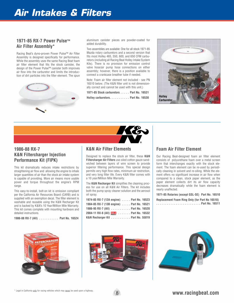
K&N Air Filter ElementsDesigned to replace the stock air filter, these K&N Filtercharger Air Filters use oiled cotton gauze sand-wiched between layers of wire screen to provide superior filtering performance. This special design permits very high flow rates, minimum air restriction, and very long filter life. Every K&N filter comes with a 10 year/Million Mile Warranty.
The K&N Recharger Kit simplifies the cleaning proc-ess for use on all K&N Air Filters. The kit includes both the pump spray cleaner solution and the aerosol oil spray.
1974-85 RX-7 (12A engine) . . . . . Part No. 16523 1984-85 RX-7 (13B engine) . . . . . Part No. 16521 1986-95 RX-7 (All) . . . . . . . . . . . Part No. 165202004-11 RX-8 (All) . . . . . . . Part No. 16532K&N Recharger Kit . . . . . . . . . . . Part No. 55019
1986-88 RX-7 K&N Filtercharger Injection Performance Kit (FIPK)This kit dramatically reduces intake restrictions by straightening air flow and allowing the engine to inhale larger quantities of air than the stock air intake system is capable of providing. More air means more usable power and torque throughout the engine’s RPM range.
This easy-to-install, bolt-on kit is emission compliant per the California Air Resources Board (CARB) and is supplied with an exemption decal. The filter element is washable and reusable using the K&N Recharger Kit and is backed by K&N’s 10 Year/Million Mile Warranty. This kit comes complete with mounting hardware and detailed instructions.
1986-88 RX-7 (All) . . . . . . . . . . . Part No. 16524
Foam Air Filter ElementOur Racing Beat-designed foam air filter element consists of polyurethane foam over a metal screen form that interchanges exactly with the stock ele-ment. The foam element can be re-used by periodi-cally cleaning in solvent and re-oiling. While the ele-ment offers no significant increase in air flow when compared to a clean, stock paper element, as the paper element collects dirt its air flow capacity decreases dramatically while the foam element is nearly unaffected.
1971-85 Rotaries (except GSL-SE) Part No. 16510
Replacement Foam Ring Only (for Part No 16510) . . . . . . . . . . . . . . . . . . . . . . . . . Part No. 16511
1971-85 RX-7 Power Pulse™ Air Filter Assembly*Racing Beat’s dyno-proven Power Pulse™ Air Filter Assembly is designed specifically for performance. While the assembly uses the same Racing Beat foam air filter element that fits the stock canister, the design of the Power Pulse™ canister both improves air flow into the carburetor and limits the introduc-tion of dirt particles into the filter element. The spun
aluminum canister pieces are powder-coated for added durability.
Two assemblies are available: One for all stock 1971-85 Mazda rotary carburetors and a second version that fits most Holley 465, 550, 600, and 650 CFM carbu-retors (including all Racing Beat Holley Intake System Kits). There is no provision for emission control valve hose/air pump hose connections on either assembly; however, there is a position available to connect a crankcase breather tube if needed.
Note: Foam air filter element not included - see PN 16510 below. (The K&N filter unit is not dimension-ally correct and cannot be used with this unit.)
1971-85 Stock carburetors . . . . . Part No. 16531
Holley carburetors . . . . . . . . . . . Part No. 16530
* Legal in California only for racing vehicles which may never be used upon a highway.
Air Intakes & Filters
RX-8PRODUCT
Holley Carburetor

Designed to offer performance improvements with-out sacrificing drivability, the Racing Beat intake system is the final result of hundreds of hours of dyno test sessions and on-road testing.
The major components of the REVi Intake System include: an OEM-style high-density polyethylene air box assembly, exclusive custom-designed K&N air filter element, machined-aluminum mass air flow sensor tube, and a tuned-length air inlet horn. Unlike the majority of the aftermarket intake systems on the market, the Racing Beat intake system retains one of the important mesh screens in the intact tract to aid with the even distribution of airflow across the mass air sensor. The retention of this screen minimizes the possibility of “rough idle” issues that may occur if both stock screens are eliminated. The REVi intake system also addresses one of the most common complaints regarding aftermarket intakes for the RX-8 – extremely loud intake noise! As compared to other “tube-and-filter” intake kits, the REVi intake produces a modest intake sound with only a 2-3 decibel increase over the stock system.
This kit comes complete with all required components, a genuine K&N washable / reusable cotton filter, hardware kit, and fully-illustrated, step-by-step installation instructions.
2004-11 RX-8 . . . . . . . . . . . . . . . . . . . . . . . . . . . . . . . . . . . . . . . Part No. 18299Replacement K&N Filter . . . . . . . . . . . . . . . . . . . . . . . . . . . . . . . . . . . . Part No. 16533
RX-8 REVi Intake System
RX-8 Ram Air DuctRacing Beat offers our Ram Air Duct for use with the REVi Intake Kit. The inlet of this duct is positioned in the mouth opening of the Mazda RX-8 to allow cooler ambient air to be force-fed directly into the REVi intake tract, converting your intake into a true “cold-air” intake system!
Designed by Racing Beat, this high-density polyethylene intake duct mounts behind the nose of your RX-8 and directs air through the lower portion of the upper opening into the inlet of the REVi Intake Kit. This duct can also be used with the stock intake box or aftermarket intake kits to direct cooler air into the engine compartment. Contact us for specific information on compatibility.
The installation of this duct requires the removal of the nose from the RX-8 and can easily be undertaken by 1-2 people in about an hour. Fully detailed instruc-tions, with numerous photos included, will guide you through the installation process.
2004-08 RX-8 . . . . . . . . . . . . . . . . . . . . . . . . . . . . Part No. 182982009-11 RX-8 . . . . . . . . . . . . . . . . . . . . . . . . . . . . Part No. 18297
RX-8PRODUCT
RX-8PRODUCT
GenuineFilter
Washable & Reusable
Complete Bolt-on Kit Includes Everything Needed For Installation
High Flow Cold Air Intake SystemCARB Exempt
Emissions Legal
RX-8PRODUCT
Section
www.racingbeat.com
The carburetors and manifolds used in these Holley Kits are also available separately:
10* Legal in California only for racing vehicles which may never be used upon a highway.
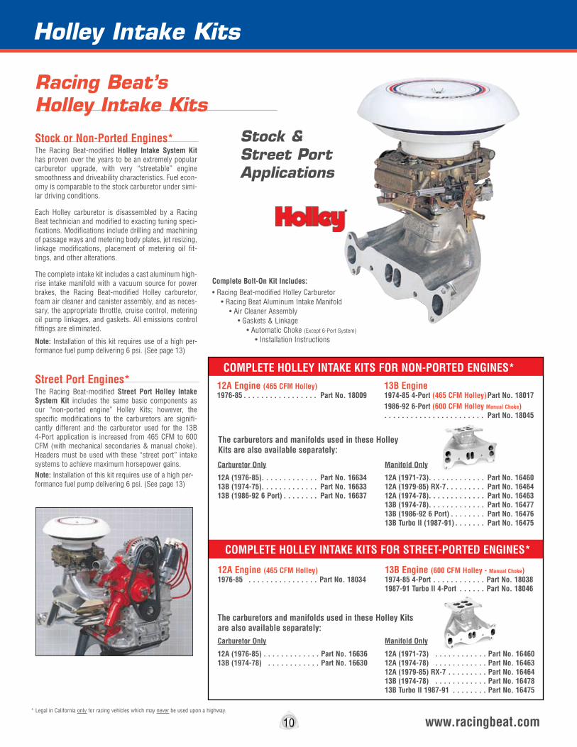
12A Engine (465 CFM Holley)1976-85 . . . . . . . . . . . . . . . . Part No. 18034
13B Engine (600 CFM Holley - Manual Choke)1974-85 4-Port . . . . . . . . . . . . Part No. 180381987-91 Turbo II 4-Port . . . . . . Part No. 18046
Complete Bolt-On Kit Includes: • Racing Beat-modified Holley Carburetor • Racing Beat Aluminum Intake Manifold • Air Cleaner Assembly • Gaskets & Linkage • Automatic Choke (Except 6-Port System) • Installation Instructions
The carburetors and manifolds used in these Holley Kits are also available separately:
Carburetor Only
12A (1976-85). . . . . . . . . . . . . Part No. 16634 13B (1974-75). . . . . . . . . . . . . Part No. 1663313B (1986-92 6 Port) . . . . . . . . Part No. 16637
Manifold Only
12A (1971-73). . . . . . . . . . . . . Part No. 16460 12A (1979-85) RX-7 . . . . . . . . . Part No. 16464 12A (1974-78). . . . . . . . . . . . . Part No. 16463 13B (1974-78). . . . . . . . . . . . . Part No. 1647713B (1986-92 6 Port) . . . . . . . . Part No. 1647613B Turbo II (1987-91) . . . . . . . Part No. 16475
12A Engine (465 CFM Holley)1976-85 . . . . . . . . . . . . . . . . . Part No. 18009
13B Engine1974-85 4-Port (465 CFM Holley) Part No. 180171986-92 6-Port (600 CFM Holley Manual Choke) . . . . . . . . . . . . . . . . . . . . . . . Part No. 18045
COMPLETE HOLLEY INTAKE KITS FOR NON-PORTED ENGINES*
COMPLETE HOLLEY INTAKE KITS FOR STREET-PORTED ENGINES*
Holley Intake Kits
Racing Beat’sHolley Intake Kits
Stock & Street Port Applications
Stock or Non-Ported Engines*The Racing Beat-modified Holley Intake System Kit has proven over the years to be an extremely popular carburetor upgrade, with very “streetable” engine smoothness and driveability characteristics. Fuel econ-omy is comparable to the stock carburetor under simi-lar driving conditions.
Each Holley carburetor is disassembled by a Racing Beat technician and modified to exacting tuning speci-fications. Modifications include drilling and machining of passage ways and metering body plates, jet resizing, linkage modifications, placement of metering oil fit-tings, and other alterations.
The complete intake kit includes a cast aluminum high-rise intake manifold with a vacuum source for power brakes, the Racing Beat-modified Holley carburetor, foam air cleaner and canister assembly, and as neces-sary, the appropriate throttle, cruise control, metering oil pump linkages, and gaskets. All emissions control fittings are eliminated.
Note: Installation of this kit requires use of a high per-formance fuel pump delivering 6 psi. (See page 13)
Street Port Engines*The Racing Beat-modified Street Port Holley Intake System Kit includes the same basic components as our “non-ported engine” Holley Kits; however, the specific modifications to the carburetors are signifi-cantly different and the carburetor used for the 13B 4-Port application is increased from 465 CFM to 600 CFM (with mechanical secondaries & manual choke). Headers must be used with these “street port” intake systems to achieve maximum horsepower gains.Note: Installation of this kit requires use of a high per-formance fuel pump delivering 6 psi. (See page 13)
Carburetor Only
12A (1976-85) . . . . . . . . . . . . . Part No. 16636 13B (1974-78) . . . . . . . . . . . . Part No. 16630
Manifold Only
12A (1971-73) . . . . . . . . . . . . Part No. 16460 12A (1974-78) . . . . . . . . . . . . Part No. 16463 12A (1979-85) RX-7 . . . . . . . . . Part No. 16464 13B (1974-78) . . . . . . . . . . . . Part No. 1647813B Turbo II 1987-91 . . . . . . . . Part No. 16475
Holley Intake Kits
www.racingbeat.com
Header Heat Shield*The Header Heat Shield prevents much of the heat radiated by the headers from reaching the Holley or Weber intake manifold, reducing the intake tempera-ture and allowing the engine to produce slightly more power. Also, the fuel in the carburetor float bowls is less likely to boil when a “hot” engine is shut off. (Cannot be used with the stock exhaust manifold.)
79-95 12A/13B All . . . . . . . . . . . Part No. 16219
11* Legal in California only for racing vehicles which may never be used upon a highway.
Holley Manual Choke Cable & Mounting BracketThe ideal item to finish the installation of your manual choke equipped carburetor is this simple cable kit. The cable length is 6 feet in length and and features a control knob with the “Holley” name proudly displayed.
Intended as an add-on item, this cable can be routed through the firewall and into the cockpit and mounted using the Bracket Kit.
Holley Manual Choke Cable . . . . . . Part No.16645
Manual Choke Bracket . . . . . . . . . Part No.16646
Holley Race Float Bowl KitThis Holley Race Float Bowl Kit will convert a regular 465 CFM carburetor to “center” pivot float bowls. These float bowls prevent excess fuel from entering the carburetor during full-throttle cornering, minimizing the “sloshing” of fuel into the throttle bores from the discharge nozzles.
Race Float Bowl Kit . . . . . . . . . . Part No. 16641
Bridge Port Applications
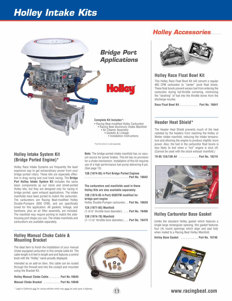
Holley Intake System Kit (Bridge Ported Engine)*Holley Race Intake Systems are frequently the least expensive way to get extraordinary power from your bridge ported rotary. These kits are especially effec-tive in drag racing and oval track racing. The Bridge Port Holley Intake System Kit includes the same basic components as our stock and street-ported Holley kits, but they are designed only for racing in bridge ported, open exhaust applications. The intake manifolds have been ported to match the carburetor. The carburetors are Racing Beat-modified Holley Double-Pumpers (650 CFM), and are specifically tuned for this application. All gaskets, linkage, and hardware, plus an air filter assembly, are included. The manifold may require porting to match the side-housing port shape you use. The intake manifolds and carburetors are available separately.
Note: The bridge ported intake manifold has no vacu-um source for power brakes. This kit has no provision for a choke mechanism. Installation of this kit requires use of a high performance fuel pump delivering 6 psi. (See page 13)
13B (1974-85) 4-Port Bridge Ported Engines . . . . . . . . . . . . . . . . . . . . . . . . . Part No. 18042
The carburetors and manifolds used in these Holley Kits are also available separately:
13B (1974-85 4-Port) 650CFM modified for bridge-port engine Holley Double-Pumper carburetor . . Part No. 16639
12A (1971-85) Manifold (1-9/16” throttle bore diameter) . . . Part No. 16466
13B (1974-78) Manifold (1-11/16” throttle bore diameter) . . . Part No. 16479
Complete Kit Includes*: • Racing Beat-modified Holley Carburetor • Racing Beat Aluminum Intake Manifold • Air Cleaner Assembly • Gaskets & Linkage • Installation Instructions
*Fuel line shown is sold separately.
Holley Accessories
Holley Carburetor Base GasketUnlike the standard Holley gasket which features a single large rectangular opening, this gasket features four (4) round openings which align and seal fully when mated to a Racing Beat Holley Manifold.
Holley Base Gasket . . . . . . . . . . Part No. 16746
Weber Carburetor Components
12 www.racingbeat.com* Legal in California only for racing vehicles which may never be used upon a highway.
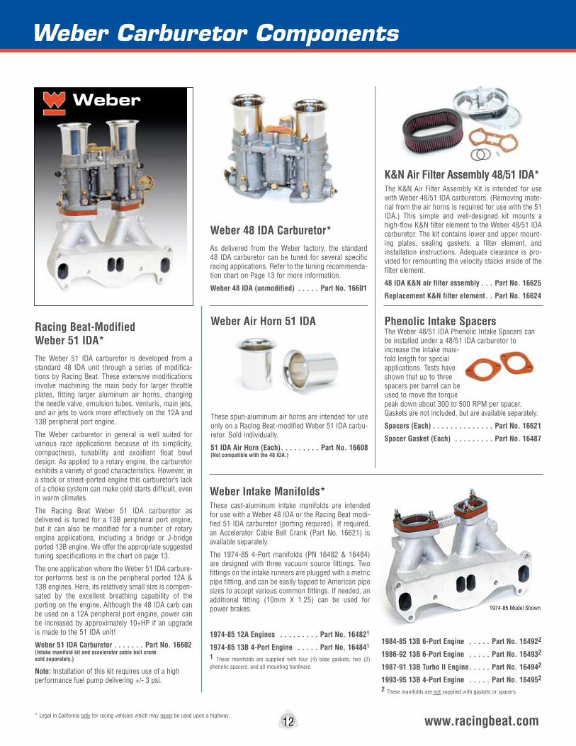
Racing Beat-Modified Weber 51 IDA*The Weber 51 IDA carburetor is developed from a standard 48 IDA unit through a series of modifica-tions by Racing Beat. These extensive modifications involve machining the main body for larger throttle plates, fitting larger aluminum air horns, changing the needle valve, emulsion tubes, venturis, main jets, and air jets to work more effectively on the 12A and 13B peripheral port engine.
The Weber carburetor in general is well suited for various race applications because of its simplicity, compactness, tunability and excellent float bowl design. As applied to a rotary engine, the carburetor exhibits a variety of good characteristics. However, in a stock or street-ported engine this carburetor’s lack of a choke system can make cold starts difficult, even in warm climates.
The Racing Beat Weber 51 IDA carburetor as delivered is tuned for a 13B peripheral port engine, but it can also be modified for a number of rotary engine applications, including a bridge or J-bridge ported 13B engine. We offer the appropriate suggested tuning specifications in the chart on page 13.
The one application where the Weber 51 IDA carbure-tor performs best is on the peripheral ported 12A & 13B engines. Here, its relatively small size is compen-sated by the excellent breathing capability of the porting on the engine. Although the 48 IDA carb can be used on a 12A peripheral port engine, power can be increased by approximately 10+HP if an upgrade is made to the 51 IDA unit!
Weber 51 IDA Carburetor . . . . . . . Part No. 16602 (Intake manifold kit and accelerator cable bell crank sold separately.)
Note: Installation of this kit requires use of a high performance fuel pump delivering +/- 3 psi.
Weber 48 IDA Carburetor*As delivered from the Weber factory, the standard 48 IDA carburetor can be tuned for several specific racing applications. Refer to the tuning recommenda-tion chart on Page 13 for more information.
Weber 48 IDA (unmodified) . . . . . Part No. 16601
Weber Intake Manifolds*These cast-aluminum intake manifolds are intended for use with a Weber 48 IDA or the Racing Beat modi-fied 51 IDA carburetor (porting required). If required, an Accelerator Cable Bell Crank (Part No. 16621) is available separately.
The 1974-85 4-Port manifolds (PN 16482 & 16484) are designed with three vacuum source fittings. Two fittings on the intake runners are plugged with a metric pipe fitting, and can be easily tapped to American pipe sizes to accept various common fittings. If needed, an additional fitting (10mm X 1.25) can be used for power brakes.
1974-85 12A Engines . . . . . . . . . Part No. 164821
1974-85 13B 4-Port Engine . . . . . Part No. 164841
1 These manifolds are supplied with four (4) base gaskets, two (2) phenolic spacers, and all mounting hardware.
1984-85 13B 6-Port Engine . . . . . Part No. 164922
1986-92 13B 6-Port Engine . . . . . Part No. 164932
1987-91 13B Turbo II Engine . . . . . Part No. 164942
1993-95 13B 4-Port Engine . . . . . Part No. 164952
2 These manifolds are not supplied with gaskets or spacers.
K&N Air Filter Assembly 48/51 IDA*The K&N Air Filter Assembly Kit is intended for use with Weber 48/51 IDA carburetors. (Removing mate-rial from the air horns is required for use with the 51 IDA.) This simple and well-designed kit mounts a high-flow K&N filter element to the Weber 48/51 IDA carburetor. The kit contains lower and upper mount-ing plates, sealing gaskets, a filter element, and installation instructions. Adequate clearance is pro-vided for remounting the velocity stacks inside of the filter element.
48 IDA K&N air filter assembly . . . Part No. 16625
Replacement K&N filter element . . Part No. 16624
Weber Air Horn 51 IDA
These spun-aluminum air horns are intended for use only on a Racing Beat-modified Weber 51 IDA carbu-retor. Sold individually.
51 IDA Air Horn (Each) . . . . . . . . . Part No. 16608 (Not compatible with the 48 IDA.)
Phenolic Intake SpacersThe Weber 48/51 IDA Phenolic Intake Spacers can be installed under a 48/51 IDA carburetor to increase the intake mani-fold length for special applications. Tests have shown that up to three spacers per barrel can be used to move the torque peak down about 300 to 500 RPM per spacer. Gaskets are not included, but are available separately.
Spacers (Each) . . . . . . . . . . . . . . Part No. 16621
Spacer Gasket (Each) . . . . . . . . . Part No. 16487
Weber
1974-85 Model Shown

13 www.racingbeat.com
Stock Port Engine13B Engine (6-Port) Venturi - 40mm • Fuel Jet - No. 195 Air Jet - No. 205 • Emulsion tube - F-4 Needle Valve - 300
Street Port Engine Equipped with headers & stock muffler
12A EngineVenturi - 37mm • Fuel Jet - No. 170 Air Jet - No. 150 • Emulsion tube - F-11 Needle valve - No. 250
13B Engine (4-port)Venturi - 38mm • Fuel Jet - No. 190 Air Jet - No. 160 • Emulsion Tube - F-11 Needle Valve - No. 250
12A Bridge Port Engine(Equipped with open headers)
12A EngineVenturi - 42mm • Fuel Jet - No. 240 Air Jet - No. 170 • Emulsion tube - F-11 Needle Valve - No. 300
13B EngineNot used - Carburetor too small.
12A Peripheral Port Engine(Equipped with open headers)
12A EngineVenturi - 43mm • Fuel Jet - No. 230 Air Jet - No. 125 • Emulsion tube - F-8 Needle Valve - No. 300
13B EngineNot used - Carburetor too small.
12A Peripheral Port Engine(Equipped with open headers)
Venturi - 43mm • Fuel Jet - No. 235 Air Jet - No. 130 • Emulsion tube - F-8
Note: Correct size needle valve (300) supplied with RB 51 IDA carburetor.
Street Port Engine51 IDA carburetor is not recommended for use on a 12A or 13B street port engine.
Stock Port Engine51 IDA carburetor is not recommended for use on a 12A or 13B stock engine.
13B Bridge Port Engine(Equipped with open headers)
12A EngineNot used - Carburetor too large.
13B Engine (4-Port)Venturi - 45mm • Fuel Jet - No. 235 Air Jet - No. 165 • Emulsion tube F-11Note: Correct size needle valve (300) supplied with RB 51 IDA carburetor.
The 48 IDA is delivered as configured by Weber. Use the following guidelines as a starting point when tuning the carburetor for your application.
Weber - 48 IDA Carburetor Racing Beat - 51 IDA CarburetorAs delivered, the Racing Beat-modified 51 IDA carburetor is tuned for a 13B Peripheral Port engine. Refer to the guidelines below for your application.
The following recommendations are provided as guide for tuning a Weber carburetor for various rotary engine applications. These settings are a result of Racing Beat’s tuning experience with the Weber carburetor - your actual settings may differ from these guidelines.
Weber Carburetor Tuning Recommendations for Rotary Engine Applications
Carburetor Components
Accelerator CableBell Crank
This bell crank unit can be easily mounted to a Weber carburetor to facilitate the attachment of the throttle cable.
Bell Crank (48/51 IDA Weber) . . . Part No. 16627
13B Peripheral Port Engine(Equipped with open headers)
As delivered, the Racing Beat-modified 51 IDA carburetor is tuned for a 13B Peripheral Port engine using these components:
Venturi - 46mm • Fuel Jet - No. 240 Air Jet - No. 110 • Needle valve - 300 Emulsion Tube - F-8
Weber Air Horn Intake Screens Nothing invokes memories of early racing days than the classic look of a simple intake air screen mounted atop an aggressive looking carburetor intake horn. The mechanical simplicity and beauty of the Weber carburetor is perfectly matched in the basic design and functionality of these protective screens. We offer a PAIR of triple-layered mesh screens for use on any 70mm ID air horn, which happens to the exact size of the intake horns offered on both the Weber 48 IDA and 51-IDA carburetors we offer. These stainless steel screens are hand-crafted in the USA and feature a molded silicone base (with securing groove) to ensure excellent longevity, fitting, and durability.
Weber 48/51 IDA Intake Screens . . Part No. 16627
Weber Carburetor Rebuild Kit This genuine Weber Carburetor Rebuild Kit (Part number 92.1632.05) is intend for use on a Weber 48 IDA or Racing Beat-51IDA carburetor. Parts included are:
Top Cover Gasket, Needle Valve - 200 (2mm), Fuel Filter, Fuel Filter Cover Gasket, Throttle Shaft Lock Washers (2), Small Rubber O-Rings (2), Small Metal Crush Washers (2), Fuel Banjo Fitting Washers (2), Throttle Shaft Screws (4)
Note: The needle valve supplied with this kit is intended for use with the 48 IDA carburetor only! The needle valve supplied with the Racing Beat 51IDA carburetor utilizes a larger 300 (3mm) needle valve.
Weber Carburetor Rebuild Kit . . . . Part No. 16623
Weber & Dell’orto Intake ComponentsThe upper manifolds listed below can be used to mount Weber and Dell’orto sidedraft carburetors to the 12A and 13B engine.
The following carburetors will mount to the Racing Beat upper manifold sections below:
Weber 48 IDA Dell’orto 40, 45, 48, 50, 55 DCOE
Sidedraft Intake Manifolds Upper Manifold Section - Connects to stock 1984-85 (13B 6-Port) manifold & Racing Beat Lower Manifolds (PN 18111 & 18112) . . . . . . . . . . . . . . . . . . . . . . . . . Part No. 18100
Upper Manifold Section - Connects to stock 1986-92 (13B 6-Port) manifold . . . . . . . . . . . . . . . . . . . . . . . . . Part No. 18101
Lower Manifold Section (12A) . . . Part No. 18111
Lower Manifold Section 1976-78 (13B 4-Port) . . . . . . . . . . . . . . . . . . . . . . . . . Part No. 18112
Gasket - Upper to lower manifold 1976-85 . . . . . . . . . . . . . . . . . . Part No. 16736 1986-92 . . . . . . . . . . . . . . . . . . Part No. 16740
Dell’orto Air Filter Components Foam Air Filter Element and Screen . . . . . . . . . . . . . . . . . . . . . . . . . Part No. 16515
Foam Air Filter Element (no screen) . . . . . . . . . . . . . . . . . . . . . . . . . Part No. 16516
K&N Filter 1984-85 SE - fits RB stamped Aluminum canisters only . . . . . . . . . . . . . . . Part No. 16517
K&N Filter 1976-92 - fits RB stamped steel, chrome canisters only . . . . . . . . . Part No. 16522
Heat Shield - All (except 6-Port ) . Part No. 16216
Racing Beat Dell'orto Intake Manifold
Upper & Lower Sections
Intake Components
www.racingbeat.com
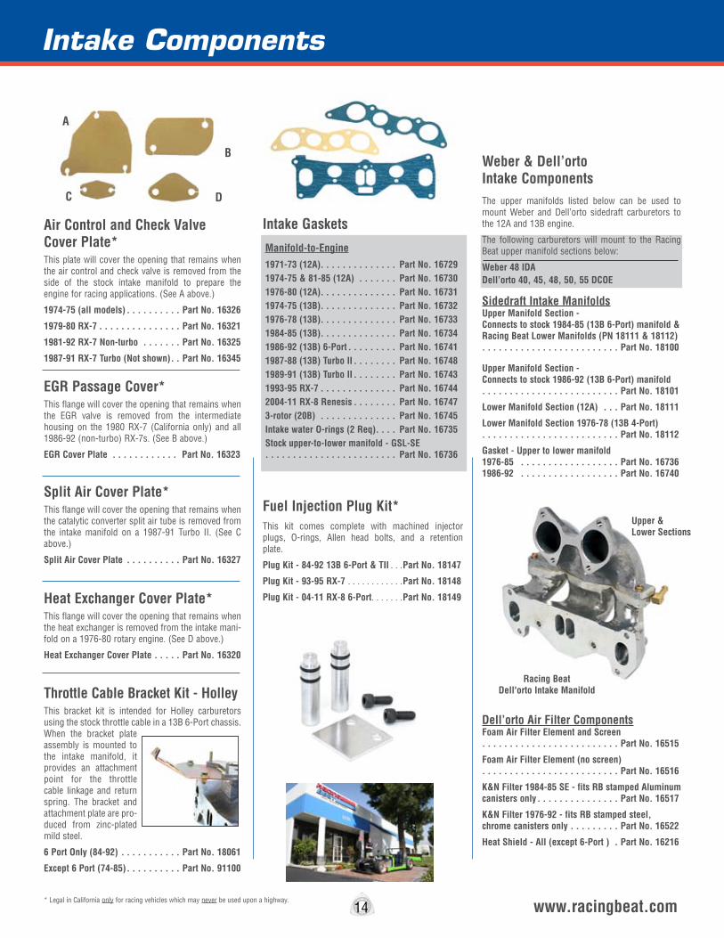
EGR Passage Cover*This flange will cover the opening that remains when the EGR valve is removed from the intermediate housing on the 1980 RX-7 (California only) and all 1986-92 (non-turbo) RX-7s. (See B above.)
EGR Cover Plate . . . . . . . . . . . . Part No. 16323
Heat Exchanger Cover Plate*This flange will cover the opening that remains when the heat exchanger is removed from the intake mani-fold on a 1976-80 rotary engine. (See D above.)
Heat Exchanger Cover Plate . . . . . Part No. 16320
Throttle Cable Bracket Kit - HolleyThis bracket kit is intended for Holley carburetors using the stock throttle cable in a 13B 6-Port chassis. When the bracket plate assembly is mounted to the intake manifold, it provides an attachment point for the throttle cable linkage and return spring. The bracket and attachment plate are pro-duced from zinc-plated mild steel.
6 Port Only (84-92) . . . . . . . . . . . Part No. 18061
Except 6 Port (74-85) . . . . . . . . . . Part No. 91100
Split Air Cover Plate*This flange will cover the opening that remains when the catalytic converter split air tube is removed from the intake manifold on a 1987-91 Turbo II. (See C above.)
Split Air Cover Plate . . . . . . . . . . Part No. 16327
Fuel Injection Plug Kit*This kit comes complete with machined injector plugs, O-rings, Allen head bolts, and a retention plate.
Plug Kit - 84-92 13B 6-Port & TII . . .Part No. 18147
Plug Kit - 93-95 RX-7 . . . . . . . . . . . .Part No. 18148
Plug Kit - 04-11 RX-8 6-Port . . . . . . .Part No. 18149
* Legal in California only for racing vehicles which may never be used upon a highway.14
Air Control and Check Valve Cover Plate*This plate will cover the opening that remains when the air control and check valve is removed from the side of the stock intake manifold to prepare the engine for racing applications. (See A above.)
1974-75 (all models) . . . . . . . . . . Part No. 16326
1979-80 RX-7 . . . . . . . . . . . . . . . Part No. 16321
1981-92 RX-7 Non-turbo . . . . . . . Part No. 16325
1987-91 RX-7 Turbo (Not shown) . . Part No. 16345
B
A
DC
Manifold-to-Engine1971-73 (12A). . . . . . . . . . . . . . Part No. 167291974-75 & 81-85 (12A) . . . . . . . Part No. 167301976-80 (12A). . . . . . . . . . . . . . Part No. 167311974-75 (13B). . . . . . . . . . . . . . Part No. 167321976-78 (13B). . . . . . . . . . . . . . Part No. 167331984-85 (13B). . . . . . . . . . . . . . Part No. 167341986-92 (13B) 6-Port . . . . . . . . . Part No. 167411987-88 (13B) Turbo II . . . . . . . . Part No. 167481989-91 (13B) Turbo II . . . . . . . . Part No. 167431993-95 RX-7 . . . . . . . . . . . . . . Part No. 167442004-11 RX-8 Renesis . . . . . . . . Part No. 167473-rotor (20B) . . . . . . . . . . . . . . Part No. 16745Intake water O-rings (2 Req) . . . . Part No. 16735Stock upper-to-lower manifold - GSL-SE . . . . . . . . . . . . . . . . . . . . . . . . Part No. 16736
Intake Gaskets
15 www.racingbeat.com* Legal in California only for racing vehicles which may never be used upon a highway.
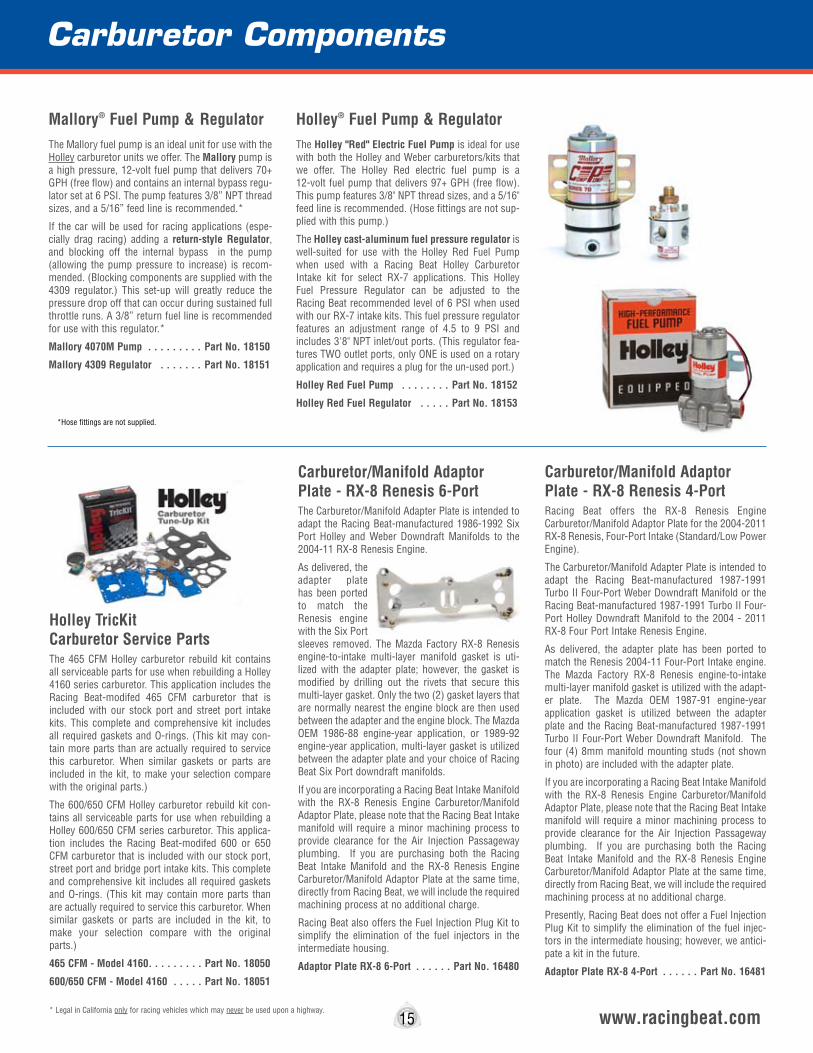
Mallory® Fuel Pump & RegulatorThe Mallory fuel pump is an ideal unit for use with the Holley carburetor units we offer. The Mallory pump is a high pressure, 12-volt fuel pump that delivers 70+ GPH (free flow) and contains an internal bypass regu-lator set at 6 PSI. The pump features 3/8” NPT thread sizes, and a 5/16” feed line is recommended.*
If the car will be used for racing applications (espe-cially drag racing) adding a return-style Regulator, and blocking off the internal bypass in the pump (allowing the pump pressure to increase) is recom-mended. (Blocking components are supplied with the 4309 regulator.) This set-up will greatly reduce the pressure drop off that can occur during sustained full throttle runs. A 3/8” return fuel line is recommended for use with this regulator.*
Mallory 4070M Pump . . . . . . . . . Part No. 18150
Mallory 4309 Regulator . . . . . . . Part No. 18151
Holley® Fuel Pump & RegulatorThe Holley "Red" Electric Fuel Pump is ideal for use with both the Holley and Weber carburetors/kits that we offer. The Holley Red electric fuel pump is a 12-volt fuel pump that delivers 97+ GPH (free flow). This pump features 3/8" NPT thread sizes, and a 5/16" feed line is recommended. (Hose fittings are not sup-plied with this pump.)
The Holley cast-aluminum fuel pressure regulator is well-suited for use with the Holley Red Fuel Pump when used with a Racing Beat Holley Carburetor Intake kit for select RX-7 applications. This Holley Fuel Pressure Regulator can be adjusted to the Racing Beat recommended level of 6 PSI when used with our RX-7 intake kits. This fuel pressure regulator features an adjustment range of 4.5 to 9 PSI and includes 3'8" NPT inlet/out ports. (This regulator fea-tures TWO outlet ports, only ONE is used on a rotary application and requires a plug for the un-used port.)
Holley Red Fuel Pump . . . . . . . . Part No. 18152
Holley Red Fuel Regulator . . . . . Part No. 18153
*Hose fittings are not supplied.
Carburetor Components
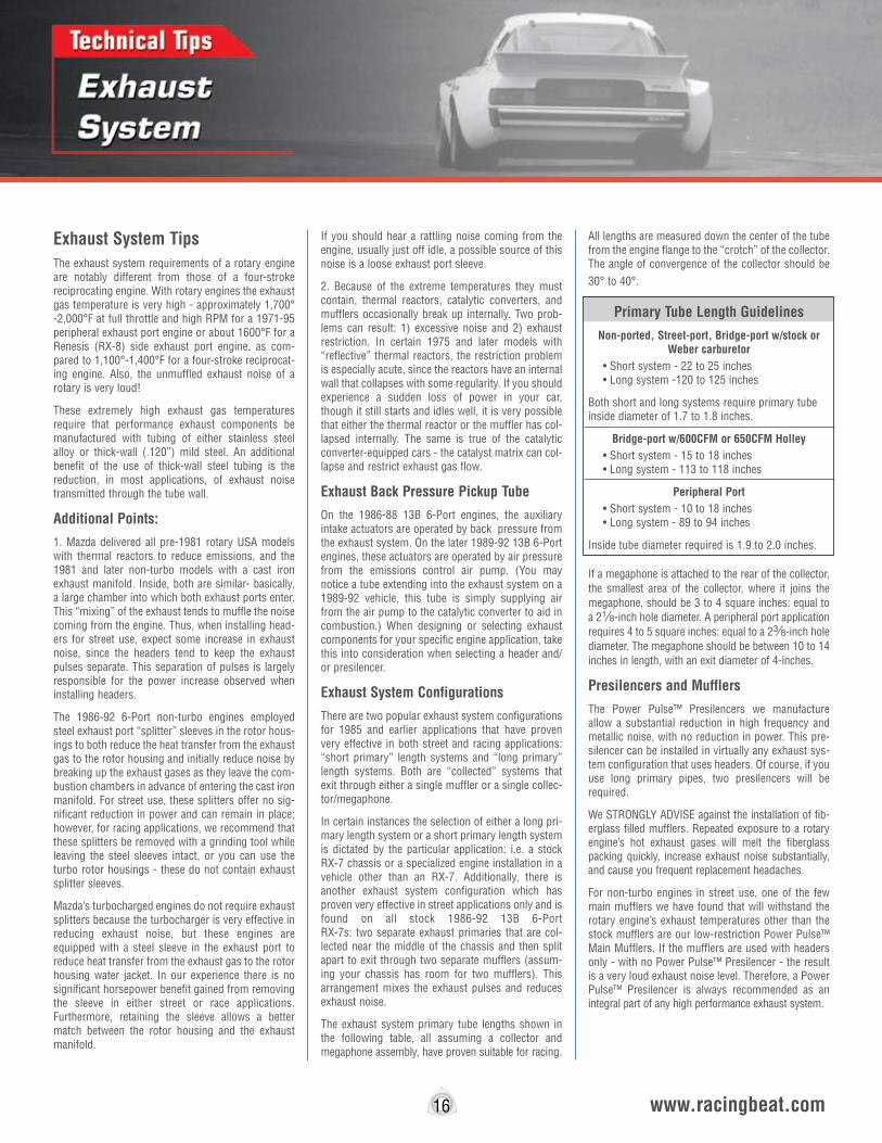
Holley TricKit Carburetor Service PartsThe 465 CFM Holley carburetor rebuild kit contains all serviceable parts for use when rebuilding a Holley 4160 series carburetor. This application includes the Racing Beat-modifed 465 CFM carburetor that is included with our stock port and street port intake kits. This complete and comprehensive kit includes all required gaskets and O-rings. (This kit may con-tain more parts than are actually required to service this carburetor. When similar gaskets or parts are included in the kit, to make your selection compare with the original parts.)
The 600/650 CFM Holley carburetor rebuild kit con-tains all serviceable parts for use when rebuilding a Holley 600/650 CFM series carburetor. This applica-tion includes the Racing Beat-modifed 600 or 650 CFM carburetor that is included with our stock port, street port and bridge port intake kits. This complete and comprehensive kit includes all required gaskets and O-rings. (This kit may contain more parts than are actually required to service this carburetor. When similar gaskets or parts are included in the kit, to make your selection compare with the original parts.)
465 CFM - Model 4160 . . . . . . . . . Part No. 18050
600/650 CFM - Model 4160 . . . . . Part No. 18051
Carburetor/Manifold Adaptor Plate - RX-8 Renesis 6-PortThe Carburetor/Manifold Adapter Plate is intended to adapt the Racing Beat-manufactured 1986-1992 Six Port Holley and Weber Downdraft Manifolds to the 2004-11 RX-8 Renesis Engine.
As delivered, the adapter plate has been ported to match the Renesis engine with the Six Port sleeves removed. The Mazda Factory RX-8 Renesis engine-to-intake multi-layer manifold gasket is uti-lized with the adapter plate; however, the gasket is modified by drilling out the rivets that secure this multi-layer gasket. Only the two (2) gasket layers that are normally nearest the engine block are then used between the adapter and the engine block. The Mazda OEM 1986-88 engine-year application, or 1989-92 engine-year application, multi-layer gasket is utilized between the adapter plate and your choice of Racing Beat Six Port downdraft manifolds.
If you are incorporating a Racing Beat Intake Manifold with the RX-8 Renesis Engine Carburetor/Manifold Adaptor Plate, please note that the Racing Beat Intake manifold will require a minor machining process to provide clearance for the Air Injection Passageway plumbing. If you are purchasing both the Racing Beat Intake Manifold and the RX-8 Renesis Engine Carburetor/Manifold Adaptor Plate at the same time, directly from Racing Beat, we will include the required machining process at no additional charge.
Racing Beat also offers the Fuel Injection Plug Kit to simplify the elimination of the fuel injectors in the intermediate housing.
Adaptor Plate RX-8 6-Port . . . . . . Part No. 16480
Carburetor/Manifold Adaptor Plate - RX-8 Renesis 4-PortRacing Beat offers the RX-8 Renesis Engine Carburetor/Manifold Adaptor Plate for the 2004-2011 RX-8 Renesis, Four-Port Intake (Standard/Low Power Engine).
The Carburetor/Manifold Adapter Plate is intended to adapt the Racing Beat-manufactured 1987-1991 Turbo II Four-Port Weber Downdraft Manifold or the Racing Beat-manufactured 1987-1991 Turbo II Four-Port Holley Downdraft Manifold to the 2004 - 2011 RX-8 Four Port Intake Renesis Engine.
As delivered, the adapter plate has been ported to match the Renesis 2004-11 Four-Port Intake engine. The Mazda Factory RX-8 Renesis engine-to-intake multi-layer manifold gasket is utilized with the adapt-er plate. The Mazda OEM 1987-91 engine-year application gasket is utilized between the adapter plate and the Racing Beat-manufactured 1987-1991 Turbo II Four-Port Weber Downdraft Manifold. The four (4) 8mm manifold mounting studs (not shown in photo) are included with the adapter plate.
If you are incorporating a Racing Beat Intake Manifold with the RX-8 Renesis Engine Carburetor/Manifold Adaptor Plate, please note that the Racing Beat Intake manifold will require a minor machining process to provide clearance for the Air Injection Passageway plumbing. If you are purchasing both the Racing Beat Intake Manifold and the RX-8 Renesis Engine Carburetor/Manifold Adaptor Plate at the same time, directly from Racing Beat, we will include the required machining process at no additional charge.
Presently, Racing Beat does not offer a Fuel Injection Plug Kit to simplify the elimination of the fuel injec-tors in the intermediate housing; however, we antici-pate a kit in the future.
Adaptor Plate RX-8 4-Port . . . . . . Part No. 16481
Exhaust System TipsThe exhaust system requirements of a rotary engine are notably different from those of a four-stroke reciprocating engine. With rotary engines the exhaust gas temperature is very high - approximately 1,700° -2,000°F at full throttle and high RPM for a 1971-95 peripheral exhaust port engine or about 1600°F for a Renesis (RX-8) side exhaust port engine, as com-pared to 1,100°-1,400°F for a four-stroke reciprocat-ing engine. Also, the unmuffled exhaust noise of a rotary is very loud!
These extremely high exhaust gas temperatures require that performance exhaust components be manufactured with tubing of either stainless steel alloy or thick-wall (.120”) mild steel. An additional benefit of the use of thick-wall steel tubing is the reduction, in most applications, of exhaust noise transmitted through the tube wall.
Additional Points:
1. Mazda delivered all pre-1981 rotary USA models with thermal reactors to reduce emissions, and the 1981 and later non-turbo models with a cast iron exhaust manifold. Inside, both are similar- basically, a large chamber into which both exhaust ports enter. This “mixing” of the exhaust tends to muffle the noise coming from the engine. Thus, when installing head-ers for street use, expect some increase in exhaust noise, since the headers tend to keep the exhaust pulses separate. This separation of pulses is largely responsible for the power increase observed when installing headers.
The 1986-92 6-Port non-turbo engines employed steel exhaust port “splitter” sleeves in the rotor hous-ings to both reduce the heat transfer from the exhaust gas to the rotor housing and initially reduce noise by breaking up the exhaust gases as they leave the com-bustion chambers in advance of entering the cast iron manifold. For street use, these splitters offer no sig-nificant reduction in power and can remain in place; however, for racing applications, we recommend that these splitters be removed with a grinding tool while leaving the steel sleeves intact, or you can use the turbo rotor housings - these do not contain exhaust splitter sleeves.
Mazda’s turbocharged engines do not require exhaust splitters because the turbocharger is very effective in reducing exhaust noise, but these engines are equipped with a steel sleeve in the exhaust port to reduce heat transfer from the exhaust gas to the rotor housing water jacket. In our experience there is no significant horsepower benefit gained from removing the sleeve in either street or race applications. Furthermore, retaining the sleeve allows a better match between the rotor housing and the exhaust manifold.
If you should hear a rattling noise coming from the engine, usually just off idle, a possible source of this noise is a loose exhaust port sleeve.
2. Because of the extreme temperatures they must contain, thermal reactors, catalytic converters, and mufflers occasionally break up internally. Two prob-lems can result: 1) excessive noise and 2) exhaust restriction. In certain 1975 and later models with “reflective” thermal reactors, the restriction problem is especially acute, since the reactors have an internal wall that collapses with some regularity. If you should experience a sudden loss of power in your car, though it still starts and idles well, it is very possible that either the thermal reactor or the muffler has col-lapsed internally. The same is true of the catalytic converter-equipped cars - the catalyst matrix can col-lapse and restrict exhaust gas flow.
Exhaust Back Pressure Pickup Tube
On the 1986-88 13B 6-Port engines, the auxiliary intake actuators are operated by back pressure from the exhaust system. On the later 1989-92 13B 6-Port engines, these actuators are operated by air pressure from the emissions control air pump. (You may notice a tube extending into the exhaust system on a 1989-92 vehicle, this tube is simply supplying air from the air pump to the catalytic converter to aid in combustion.) When designing or selecting exhaust components for your specific engine application, take this into consideration when selecting a header and/or presilencer.
Exhaust System Configurations
There are two popular exhaust system configurations for 1985 and earlier applications that have proven very effective in both street and racing applications: “short primary” length systems and “long primary” length systems. Both are “collected” systems that exit through either a single muffler or a single collec-tor/megaphone.
In certain instances the selection of either a long pri-mary length system or a short primary length system is dictated by the particular application: i.e. a stock RX-7 chassis or a specialized engine installation in a vehicle other than an RX-7. Additionally, there is another exhaust system configuration which has proven very effective in street applications only and is found on all stock 1986-92 13B 6-Port RX-7s: two separate exhaust primaries that are col-lected near the middle of the chassis and then split apart to exit through two separate mufflers (assum-ing your chassis has room for two mufflers). This arrangement mixes the exhaust pulses and reduces exhaust noise.
The exhaust system primary tube lengths shown in the following table, all assuming a collector and megaphone assembly, have proven suitable for racing.
All lengths are measured down the center of the tube from the engine flange to the “crotch” of the collector. The angle of convergence of the collector should be 30° to 40°.
Primary Tube Length Guidelines
Non-ported, Street-port, Bridge-port w/stock or Weber carburetor
• Short system - 22 to 25 inches • Long system -120 to 125 inches
Both short and long systems require primary tube inside diameter of 1.7 to 1.8 inches.
Bridge-port w/600CFM or 650CFM Holley • Short system - 15 to 18 inches • Long system - 113 to 118 inches
Peripheral Port • Short system - 10 to 18 inches • Long system - 89 to 94 inches
Inside tube diameter required is 1.9 to 2.0 inches.
If a megaphone is attached to the rear of the collector, the smallest area of the collector, where it joins the megaphone, should be 3 to 4 square inches: equal to a 28-inch hole diameter. A peripheral port application requires 4 to 5 square inches: equal to a 2a-inch hole diameter. The megaphone should be between 10 to 14 inches in length, with an exit diameter of 4-inches.
Presilencers and Mufflers
The Power Pulse™ Presilencers we manufacture allow a substantial reduction in high frequency and metallic noise, with no reduction in power. This pre-silencer can be installed in virtually any exhaust sys-tem configuration that uses headers. Of course, if you use long primary pipes, two presilencers will be required.
We STRONGLY ADVISE against the installation of fib-erglass filled mufflers. Repeated exposure to a rotary engine’s hot exhaust gases will melt the fiberglass packing quickly, increase exhaust noise substantially, and cause you frequent replacement headaches.
For non-turbo engines in street use, one of the few main mufflers we have found that will withstand the rotary engine’s exhaust temperatures other than the stock mufflers are our low-restriction Power Pulse™ Main Mufflers. If the mufflers are used with headers only - with no Power Pulse™ Presilencer - the result is a very loud exhaust noise level. Therefore, a Power Pulse™ Presilencer is always recommended as an integral part of any high performance exhaust system.
16 www.racingbeat.com
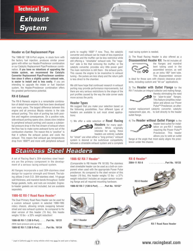
A set of Racing Beat's 304-stainless steel head-ers are the primary component in the develop-ment of a serious racing exhaust system.
All flanges incorporate a cast 304-stainless steel design for superior strength and fitment. The tub-ing utilizes 2-inch O.D. 304-stainless steel, 14-gauge wall thickness, and mandrel-bends throughout. Outlet flange gaskets, bolts, and nuts are included. Engine-to-header gaskets are not included, but are available separately.
1986-92 RX-7 Road Race Header* The Dual Primary Road Race Header can be used for a custom exhaust system in selected 1988-1992 rotary chassis, allowing simple swapping between street and race exhaust systems. As compared to the steel version of this header (15 lbs), this header weighs 10 lbs - a 33% weight reduction!
1986-88 RX-7 (13B 6-Port) . . . . .Part No. 16131(With back-pressure pick-up tube)
1989-92 RX-7 (13B 6-Port) . . . . .Part No. 16134
1986-92 RX-7 Header*(Comparable to RB Header PN 16130) The stainless steel streetable header can be used as a bolt-on com-ponent when used with the appropriate Power Pulse presilencer. As compared to the steel version of this header (19 lbs), this header weighs 12 lbs - a 37% weight reduction! Includes an oxygen sensor mount-ing flange and all required mounting hardware.
1986-92 RX-7 (13B 6-Port) . . . . .Part No. 16132*
Header vs Cat Replacement Pipe
The 1986-92 13B 6-Port engine, in stock form with the factory fuel injection, produces similar power gains with either our Header/Presilencer combination or our Catalytic Replacement Pipe/Presilencer combi-nation. If you have no intentions of upgrading the intake system, we recommend the Catalytic Converter Replacement Pipe/Presilencer combina-tion since it offers a slightly quieter exhaust note, is easier to install and is less costly. If you are intending to upgrade the intake or fuel injection system, the Header/Presilencer combination offers the greatest performance potential.
RX-8 Exhaust
The RX-8 Renesis engine is a remarkable combina-tion of detail improvements that have been developed over many years. The largest difference between this engine and all previous Mazda rotaries is the side exhaust porting. This style of porting has both posi-tive and negative consequences. On a positive note, side exhaust porting opens slow, closes slow (relative to peripheral exhaust porting) and causes a substan-tial pressure drop in the free stream of exhaust where the flow has to make some awkward turns out of the combustion chamber. The reason this is “positive” is that it softens the exhaust pulses and cools the exhaust. This means that exhaust gas temperatures drop from 1800°F and more with peripheral exhaust
ports to roughly 1600° F now. Thus, the catalytic converter and exhaust can be made of less expensive materials and the muffler can be less restrictive while still offering a “streetable” exhaust note. The “nega-tive” side is the that removing the muffler, or the catalytic converter, provides very little power gain! The main restriction is still there - the exhaust ports. This causes the engine to be insensitive to exhaust tuning - the pulses are less sharp and the return path is less direct to the chamber.
We still have hope that continued research in exhaust porting may provide performance improvements, but there are very serious restrictions to the shape of the port profiles caused by the way the side corner seals move across the ports.
Header TypesWe suggest that you make your selection based on the following possibilities. Four different types of headers are available to suit most street applica-tions:
1) We offer a wide selection of Road Racing Headers for many appli-cations. While originally intended for racing, these headers are entirely suitable
for “street” use when either a “long primary” exhaust system is desired or the switchover compatibility between a streetable exhaust system and a complete
road racing system is needed.
2) The Road Racing Header is also offered as a Disassembled Header Kit. The kit includes all
the flanges and mandrel bent tubing used in the assembled version, as well as an extra 180° bent tube. This disassembled version
is ideal for those cars with chassis clearance prob-lems, including custom and “kit car” applications.
3) The Header with Outlet Flange for the RX-7 includes an integral collector and mating flange,
thereby eliminating the need for “pipe-to-pipe” flanges. This feature simplifies instal-lation and allows our Power Pulse™ Presilencer, an after-
market replacement catalytic converter, catalytic replacement pipe, etc.. to bolt directly to the header outlet flange.
4) The Header without Outlet Flange is the header best suited for instal-lation on pre-RX-7 models requiring the Power Pulse™ Presilencer. This header allows you to weld an outlet
flange at the angle that most easily aligns the presi-lencer under the chassis.
17 www.racingbeat.com
RX-7 Header
RX-8 Header*2004-11 RX-8 . . . . . . . . . . . Part No. 16133
RX-7 Road Race Header RX-7 Header
RX-8 Header
* Legal in California only for racing vehicles which may never be used upon a highway.
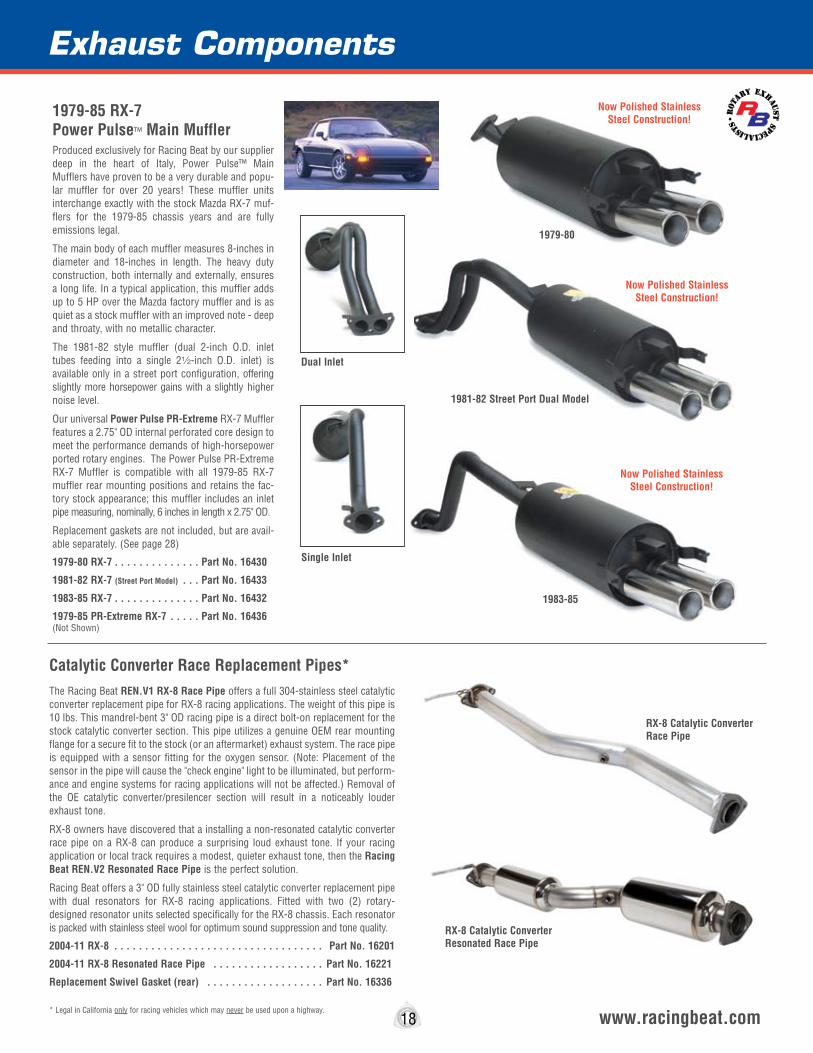
1979-85 RX-7 Power Pulse™ Main MufflerProduced exclusively for Racing Beat by our supplier deep in the heart of Italy, Power Pulse™ Main Mufflers have proven to be a very durable and popu-lar muffler for over 20 years! These muffler units interchange exactly with the stock Mazda RX-7 muf-flers for the 1979-85 chassis years and are fully emissions legal.
The main body of each muffler measures 8-inches in diameter and 18-inches in length. The heavy duty construction, both internally and externally, ensures a long life. In a typical application, this muffler adds up to 5 HP over the Mazda factory muffler and is as quiet as a stock muffler with an improved note - deep and throaty, with no metallic character.
The 1981-82 style muffler (dual 2-inch O.D. inlet tubes feeding into a single 22-inch O.D. inlet) is available only in a street port configuration, offering slightly more horsepower gains with a slightly higher noise level.
Our universal Power Pulse PR-Extreme RX-7 Muffler features a 2.75" OD internal perforated core design to meet the performance demands of high-horsepower ported rotary engines. The Power Pulse PR-Extreme RX-7 Muffler is compatible with all 1979-85 RX-7 muffler rear mounting positions and retains the fac-tory stock appearance; this muffler includes an inlet pipe measuring, nominally, 6 inches in length x 2.75" OD.
Replacement gaskets are not included, but are avail-able separately. (See page 28)
1979-80 RX-7 . . . . . . . . . . . . . . Part No. 16430
1981-82 RX-7 (Street Port Model) . . . Part No. 16433
1983-85 RX-7 . . . . . . . . . . . . . . Part No. 16432
1979-85 PR-Extreme RX-7 . . . . . Part No. 16436(Not Shown)
Section
18 www.racingbeat.com
1979-80
1983-85
Single Inlet
Dual Inlet
rot
ary exhau
stspecialis
ts•
* Legal in California only for racing vehicles which may never be used upon a highway.
1981-82 Street Port Dual Model
Exhaust Components
Catalytic Converter Race Replacement Pipes*The Racing Beat REN.V1 RX-8 Race Pipe offers a full 304-stainless steel catalytic converter replacement pipe for RX-8 racing applications. The weight of this pipe is 10 lbs. This mandrel-bent 3" OD racing pipe is a direct bolt-on replacement for the stock catalytic converter section. This pipe utilizes a genuine OEM rear mounting flange for a secure fit to the stock (or an aftermarket) exhaust system. The race pipe is equipped with a sensor fitting for the oxygen sensor. (Note: Placement of the sensor in the pipe will cause the "check engine" light to be illuminated, but perform-ance and engine systems for racing applications will not be affected.) Removal of the OE catalytic converter/presilencer section will result in a noticeably louder exhaust tone.
RX-8 owners have discovered that a installing a non-resonated catalytic converter race pipe on a RX-8 can produce a surprising loud exhaust tone. If your racing application or local track requires a modest, quieter exhaust tone, then the Racing Beat REN.V2 Resonated Race Pipe is the perfect solution.
Racing Beat offers a 3" OD fully stainless steel catalytic converter replacement pipe with dual resonators for RX-8 racing applications. Fitted with two (2) rotary-designed resonator units selected specifically for the RX-8 chassis. Each resonator is packed with stainless steel wool for optimum sound suppression and tone quality.
2004-11 RX-8 . . . . . . . . . . . . . . . . . . . . . . . . . . . . . . . . . . Part No. 16201
2004-11 RX-8 Resonated Race Pipe . . . . . . . . . . . . . . . . . . Part No. 16221
Replacement Swivel Gasket (rear) . . . . . . . . . . . . . . . . . . . Part No. 16336
RX-8 Catalytic Converter Resonated Race Pipe
RX-8 Catalytic Converter Race Pipe
Now Polished Stainless Steel Construction!
Now Polished Stainless Steel Construction!
Now Polished Stainless Steel Construction!
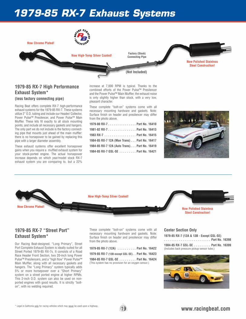
1979-85 RX-7 Exhaust Systems
19 www.racingbeat.com
1979-85 RX-7 High Performance Exhaust System* (less factory connecting pipe)
Racing Beat offers complete RX-7 high-performance exhaust systems for the 1979-85 RX-7. These systems utilize 2” O.D. tubing and include our Header/ Collector, Power Pulse™ Presilencer, and Power Pulse™ Main Muffler. These kits fit exactly to all stock mounting points, and include all necessary gaskets and hangers. The only part we do not include is the factory connect-ing pipe that mounts just ahead of the main muffler: there is no horsepower to be gained by replacing this pipe with a larger diameter assembly.
These exhaust systems offer excellent horsepower gains when you require a muffled exhaust system for your stock-ported engine. The actual horsepower increase depends on which year/model stock RX-7 exhaust system you are comparing to, but a 22%
increase at 7,000 RPM is typical. Thanks to the combined efforts of the Power Pulse™ Presilencer and the Power Pulse™ Main Muffler, the exhaust noise is only slightly higher than stock, with a very low, pleasant character.
These complete “bolt-on” systems come with all necessary mounting hardware and gaskets. Note: Surface finish on header and presilencer may differ from the photo above.
1979-80 RX-7 . . . . . . . . . . . . . . . Part No. 16410
1981-82 RX-7 . . . . . . . . . . . . . . . Part No. 16413
1983 RX-7 . . . . . . . . . . . . . . . . . Part No. 16415
1984-85 RX-7 12A (Man Trans) . . . Part No. 16417
1984-85 RX-7 12A (Auto Trans) . . . Part No. 16419
1984-85 RX-7 GSL-SE . . . . . . . . . Part No. 16421
1979-85 RX-7 “Street Port” Exhaust System*Our Racing Beat-designed, “Long Primary”, Street Port Complete Exhaust System is ideally suited for all Street Ported 1979-85 RX-7s. It consists of a Road Race Header Front Section, two 20-inch long Power Pulse™ Presilencers, and a “high flow” Power Pulse™ Main Muffler, along with all necessary gaskets and hangers. The “Long Primary” system typically adds 5% or more horsepower over a “Short Primary” system on a street ported engine at higher RPMs. This 2-inch O.D. system can also be used on non-ported engines with good results. It is strictly “bolt-on”, with no welding required.
These complete “bolt-on” systems come with all necessary mounting hardware and gaskets. Note: Surface finish on header and presilencer may differ from the photo above.
1979-85 RX-7 (12A) . . . . . . . . . . Part No. 16422
1979-85 RX-7 (13B-except GSL-SE) . . Part No. 16423
1984-85 RX-7 GSL-SE . . . . . . . . . Part No. 16424 (This system has no provision for an oxygen sensor.)
Center Section Only1979-85 RX-7 (12A & 13B - Except GSL-SE) . . . . . . . . . . . . . . . . . . . . . . . . . Part No. 16398
1984-85 RX-7 GSL-SE . . . . . . . . . Part No. 16399 (Includes back pressure pickup sensor tube.)
* Legal in California only for racing vehicles which may never be used upon a highway.
(Not Included)
Factory (Stock) Connecting Pipe
rot
ary exhau
stspecialis
ts•
Now Chrome Plated!
Now High-Temp Silver Coated!
Now Polished Stainless Steel Construction!
Now Chrome Plated!
Now High-Temp Silver Coated!
Now Polished Stainless Steel Construction!
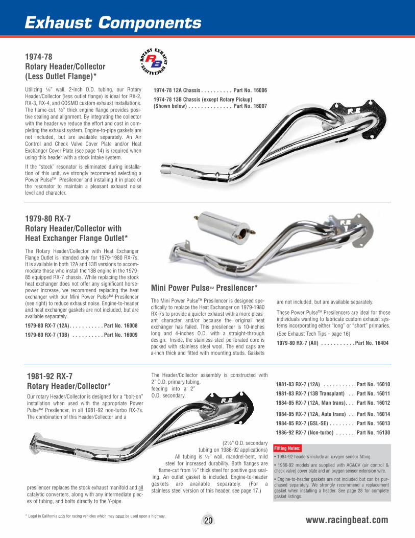
1974-78 Rotary Header/Collector (Less Outlet Flange)*Utilizing 8” wall, 2-inch O.D. tubing, our Rotary Header/Collector (less outlet flange) is ideal for RX-2, RX-3, RX-4, and COSMO custom exhaust installations. The flame-cut, 2” thick engine flange provides posi-tive sealing and alignment. By integrating the collector with the header we reduce the effort and cost in com-pleting the exhaust system. Engine-to-pipe gaskets are not included, but are available separately. An Air Control and Check Valve Cover Plate and/or Heat Exchanger Cover Plate (see page 14) is required when using this header with a stock intake system.
If the “stock” resonator is eliminated during installa-tion of this unit, we strongly recommend selecting a Power Pulse™ Presilencer and installing it in place of the resonator to maintain a pleasant exhaust noise level and character.
1974-78 12A Chassis . . . . . . . . . . Part No. 16006
1974-78 13B Chassis (except Rotary Pickup) (Shown below) . . . . . . . . . . . . . . Part No. 16007
1981-92 RX-7 Rotary Header/Collector*Our rotary Header/Collector is designed for a “bolt-on” installation when used with the appropriate Power Pulse™ Presilencer, in all 1981-92 non-turbo RX-7s. The combination of this Header/Collector and a
presilencer replaces the stock exhaust manifold and all catalytic converters, along with any intermediate piec-es of tubing, and bolts directly to the Y-pipe.
The Header/Collector assembly is constructed with 2” O.D. primary tubing, feeding into a 2” O.D. secondary.
(22” O.D. secondary tubing on 1986-92 applications)
All tubing is 8” wall, mandrel-bent, mild steel for increased durability. Both flanges are
flame-cut from 2” thick steel for positive gas seal-ing. An outlet gasket is included. Engine-to-header gaskets are available separately. (For a stainless steel version of this header, see page 17.)
1981-83 RX-7 (12A) . . . . . . . . . . Part No. 16010
1981-83 RX-7 (13B Transplant) . . Part No. 16011
1984-85 RX-7 (12A, Man trans) . . . Part No. 16012
1984-85 RX-7 (12A, Auto trans) . . Part No. 16014
1984-85 RX-7 (GSL-SE) . . . . . . . . Part No. 16013
1986-92 RX-7 (Non-turbo) . . . . . . Part No. 16130
Section
20 www.racingbeat.com
1979-80 RX-7 Rotary Header/Collector with Heat Exchanger Flange Outlet*The Rotary Header/Collector with Heat Exchanger Flange Outlet is intended only for 1979-1980 RX-7s. It is available in both 12A and 13B versions to accom-modate those who install the 13B engine in the 1979-85 equipped RX-7 chassis. While replacing the stock heat exchanger does not offer any significant horse-power increase, we recommend replacing the heat exchanger with our Mini Power Pulse™ Presilencer (see right) to reduce exhaust noise. Engine-to-header and heat exchanger gaskets are not included, but are available separately.
1979-80 RX-7 (12A) . . . . . . . . . . . Part No. 16008
1979-80 RX-7 (13B) . . . . . . . . . . Part No. 16009
Mini Power Pulse™ Presilencer*The Mini Power Pulse™ Presilencer is designed spe-cifically to replace the Heat Exchanger on 1979-1980 RX-7s to provide a quieter exhaust with a more pleas-ant character and/or because the original heat exchanger has failed. This presilencer is 10-inches long and 4-inches O.D. with a straight-through design. Inside, the stainless-steel perforated core is packed with stainless steel wool. The end caps are a-inch thick and fitted with mounting studs. Gaskets
are not included, but are available separately.
These Power Pulse™ Presilencers are ideal for those individuals wanting to fabricate custom exhaust sys-tems incorporating either “long” or “short” primaries. (See Exhaust Tech Tips - page 16)
1979-80 RX-7 (All) . . . . . . . . . . .Part No. 16404
* Legal in California only for racing vehicles which may never be used upon a highway.
Exhaust Components
Fitting Notes:
• 1984-92 headers include an oxygen sensor fitting.
• 1986-92 models are supplied with AC&CV (air control & check valve) cover plate and an oxygen sensor extension wire.
• Engine-to-header gaskets are not included but can be pur-chased separately. We strongly recommend a replacement gasket when installing a header. See page 28 for complete gasket listings.
rot
ary exhau
stspecialis
ts•

Power Pulse™ Presilencer*The Power Pulse™ Presilencer is designed to be used with our wide selection of RX-7 Streetable Header/Collectors to complete a “bolt-on” configura-tion. Power Pulse™ Presilencers are also included as a sub-component in the “Down Pipe/Presilencer” assemblies we offer for all 1986-92 RX-7s.
Furthermore, these Power Pulse™ Presilencers are ideal for those individuals wanting to fabricate cus-tom exhaust systems incorporating either “long” or “short” primaries.
The Power Pulse™ Presilencer improves the charac-ter of the rotary engine’s exhaust noise, dramatically reducing the inherent, obnoxious metallic “high fre-quency” noise with virtually no power l o s s . Constructed with 28-inch O.D. per-forated stainless steel core wrapped with high-tempera-
ture stainless steel and ceramic wool, the Power Pulse™ Presilencer measures 20-inches in length with a 4” O.D.
The 1986-92 RX-7 turbo and non-turbo Power Pulse™ Presilencers are manufactured with a larger diameter 22” O.D. core pipe for improved exhaust gas flow.
Additionally, the Power Pulse™ Presilencers we offer for use with non-turbo 1984-88 6-Port engines feature the back pressure sensing tube necessary for proper operation of the 6-Port intake actuator valves.
1981-83 RX-7 . . . . . . . . . . . . . . . Part No. 16400
1984-85 RX-7 (12A, Man trans) . . . Part No. 16401
1984-85 RX-7 (12A, Auto trans) . . Part No. 16403
1984-85 RX-7 (GSL-SE) . . . . . . . . Part No. 16402
1986-88 RX-7 (Non-turbo, Man trans) . . . . . . . . . . . . . . . . . . . . . . . . . Part No. 16405
1986-88 RX-7 (Non-turbo, Auto trans) . . . . . . . . . . . . . . . . . . . . . . . . . Part No. 16407
1989-92 RX-7 (Non-turbo, Man trans) . . . . . . . . . . . . . . . . . . . . . . . . . Part No. 16408
1989-92 RX-7 (Non-turbo, Auto trans) . . . . . . . . . . . . . . . . . . . . . . . . . Part No. 16409
1987-91 RX-7 Turbo II (All) . . . . . Part No. 16406
Note: Gaskets are not included, but can be purchased separately. See page 28.
Section
21 www.racingbeat.com* Legal in California only for racing vehicles which may never be used upon a highway.
Road Racing Header *Racing Beat's Road Racing Header is the first step in building a serious racing exhaust system. The “engine-to-pipe” flange is flame cut from 2” thick flat steel to ensure superior sealing qualities. Like all of the headers we manufacture, the Road Racing Header is constructed from 2” O.D. mild steel tubing, 8”wall thickness, and mandrel-bends throughout provide efficient exhaust gas flow.
Outlet flange gaskets, bolts, and nuts are includ-ed. Engine-to-pipe gaskets are not included, but are available separately. An Air
Control & Check Valve Cover Plate (see page 14) is required when using this header with a stock intake system. The Road Race Header can also be used for a custom exhaust system in any 1971 thru 1992 rotary chassis, allowing simple swapping between street and race exhaust systems. This header can be used with the Racing Beat center section on 1979-85 applications as shown on page 19.
(For a 304-series stainless steel version of this header, see page 17.)
1971-73 (12A). . . . . . . . . . . . . . Part No. 16001
1974-78 (12A). . . . . . . . . . . . . . Part No. 16002
1974-78 (13B). . . . . . . . . . . . . . Part No. 16003
1979-85 RX-7 (12A) . . . . . . . . . . Part No. 16125
1979-85 RX-7 (13B, except 6-PI) . Part No. 16126
1984-92 RX-7 (13B, 6-Port) . . . . Part No. 16127 This header is intended as a racing header and does not include a back pressure pickup tube or O2 sensor fitting. If you required these features see possible alternates on page 22. (Note: This header is not compatible with the 1986-92 RX-7 Road Race Presilencer on page 22.)
Exhaust Components
• Straight-Through Design• Perforated Stainless Steel Core• Easy Bolt-on Design
Tech Note*: The 1984-88 13B 6-port engine requires the use of exhaust back pressure to operate the auxiliary 6-Port intake actuator valves. After the installation of a header or down-pipe, we suggest the removal of the air pump and the air control check valve assembly in order to “simplify” the engine. We supply with our header and downpipe systems the required components needed to complete the removal for these applications.
On the 1989-92 engines, the actuator valves are operated by an air pump. The air pump must be retained on these engines for the correct operation of 6-Port intake actuator valves.
3” I.D. Stainless Steel Universal Turbo PresilencerFor custom turbo applications we offer two versions of a 3” O.D. presilencer. The polished outer shell, inner core, and packing materials utilize 304 stainless steel for superior strength and longevity.
74W x 4dH x 15wL” (Shown) . . .Part No. 16434
62W x 4dH x 15wL” . . . . . . . . .Part No. 16435
Includes mounting hangers for each specific application.
Back pressure pickup tube provided on 1984-88 13B 6-Port models.

1986-92 Road Race Exhaust System & Components*Road Race Header
Racing Beat’s Road Racing Header is the first step in building a serious racing exhaust system. The engine-to-pipe flange is flame cut from 2” thick flat steel for superb exhaust gas sealing qualities. Like all of the mild steel headers we manufac-ture, the Road Racing Header is constructed with 2” O.D. tubing, 8” inch wall thickness, and mandrel-bends throughout. This header weighs approximately 15.5 lbs and is approximately 28” in length.
On the 1986-88 13B 6-Port engines, the auxiliary intake actuators are operated by backpressure from the exhaust system. Our headers for these applications offer a back pressure pickup tube that allows for the correct operation of the 6-Port intake actuators. Also included on the Road Race header is an oxygen sensor fitting for cars that require an oxygen sensor for correct operation. Outlet flange gaskets, bolts, nuts, AC & CV cover plate, and installation instructions are included. An engine-to-header gasket (PN 16309) is not included, but is available separately.
Road Race Presilencer
This Road Race Presilencer unit is equipped with dual 2” O.D. inlet and outlet tubes, and a stainless steel presilencer canister. This unit incorporates the factory hanger positions and comes complete with outlet gasket and (6) mounting bolts/nuts. This unit weighs 24 lbs and is approximately 34” in length.
Road Race Extension Tubes
Racing Beat’s Road Race Extension Tubes are intended to bolt-up to the outlets of the Road Race Y-Pipe section. These tubes come complete with (2) outlet gaskets and (4) mounting bolts/nuts.
You WILL need these Extension Tubes if:
You are 1) retaining the stock mufflers, or 2) already have or will be pur- chasing the Racing Beat Power Pulse Mufflers for the 1986-92 RX-7 (non- turbo and turbo muffler versions). It is possible that these extension tubes may be compatible with other aftermarket mufflers, but we cannot confirm fitment or outlet tip positioning with these units.
You DO NOT need these Extension Tubes if:
You will be replacing the stock mufflers, or any aftermarket muffler, with the Racing Beat Road Race Muffler units (PN 16438 & 16439).
Road Race Mufflers
Racing Beat's Road Race Mufflers are intended to bolt-up to the outlets of the Road Race Y-Pipe section only, and are not compatible with the stock y-pipe section or the Road Race Extension Tubes. These mufflers can be ordered separately for use in custom applications.
These mufflers are manufactured using 304-stainless steel canisters, tubing, flanges, and features a 2” O.D. “straight-through” design for maximum perform-ance gains. Finished with 32” O.D. polished 304 stainless steel tips, these mufflers sound as good as they look! Each bolt-on muffler comes complete with a mounting gasket and retaining hardware.
Road Race Headers (includes O2 sensor fitting)
1986-88 13B 6-Port Road Race Header (w/pickup tube) . . . . . Part No. 16128 1989-92 13B 6-Port Road Race Header . . . . . . . . . . . . . . . . . Part No. 16129
Road Race Presilencer (for use with above headers only) . . . . . . . Part No. 16448
Road Race Y-Pipe (for use with above presilencer only) . . . . . . . . Part No. 16411
Extension Tubes (for use with stock or RB Power Pulse Mufflers)
(per pair) . . . . . . . . . . . . . . . . . . . . . . . . . . . . . . . . . . . . . Part No. 16412
Road Race Mufflers (will connect to Y-Pipe above)
Road Race Right Muffler. . . . . . . . . . . . . . . . . . . . . . . . . . . Part No. 16438 Road Race Left Muffler . . . . . . . . . . . . . . . . . . . . . . . . . . . Part No. 16439
Road Race Header- includes 02 Sensor Fitting- 86-88 Model includes Back Pressure Pickup Tube Presilencer
Y-Pipe
Extension Tubes- For use with Stock or Power Pulse Mufflers
RB Power Pulse Mufflers
Road Race System Can Use Your Choice Of:- Stock Mufflers- RB Power Pulse Mufflers (Page 24 )- RB Road Race Mufflers (see below)
Dual Exhaust Power And Performance!Can be used with your existing mufflers!
* Legal in California only for racing vehicles which may never be used upon a highway. 22
Replacement rubber exhaust hangers available, see Page 25.

59 HP Gain!59 HP Gain!
1987-91 TURBO II REV-TII Complete Exhaust System*The REV-TII Complete Exhaust System incorporates a 3” O.D. down pipe from the turbo outlet into a stainless steel presilencer. From the head of the Y- pipe two 2a” O.D. pipes extend to the ceramic wool-packed rear main mufflers. This “bolt-on” exhaust sys-tem increases h o r s e p o w e r approximately 32% - a 59 HP increase on a 1987 Turbo II RX-7!
The REV-TII Complete Exhaust System reduces exhaust gas back pressure significantly, thereby allow-ing the un-assisted turbo boost pressure to increase to 10-11 psi. Our Fuel Cut Controller (Part No. 11570 or 11571) is required to prevent fuel cutoff to the rear rotor above the factory pre-set limit.
This system includes all necessary mounting hardware and gaskets (does not include turbo outlet gasket).
We also offer individually the components comprising the REV-TII Complete Exhaust System for those indi-viduals wishing to build custom exhaust systems for their specialized applications.
1987-91 Turbo II . . . . . . . . . . . . . Part No. 16425
REV-TII Individual Components & Gaskets3” O.D. Down Pipe . . . . . . . . . . Part No. 16425D Replacement Gasket (rear) . . . Part No. 16340
Presilencer (Approximate overall length - 29”) 3” O.D. inlet and outlet) . . . . . . Part No. 16425P Replacement Gasket (rear) . . . Part No. 16340
Y-Pipe . . . . . . . . . . . . . . . . . . . Part No. 16425Y Replacement Gasket (rear) . . . Part No. 16339
Left Muffler . . . . . . . . . . . . . . . Part No. 16450 Right Muffler . . . . . . . . . . . . . . Part No. 16449 Replacement Muffler Gasket . Part No. 16339
* Legal in California only for racing vehicles which may never be used upon a highway.
Fuel Cut Controller
Y-Pipe
3” O.D. Presilencer
3” O.D. Down Pipe
The Ultimate Exhaust System For Your Turbo II RX-7!
RB Power Pulse Mufflers (2a” O.D. Inlet Tubing)
Fuel Cut Controller*The Fuel Cut Controller allows the Turbo II to run at higher-than-stock turbo boost pressures without experiencing pre-programmed rear rotor fuel cutoff. The Fuel Cut controller essentially deceives the ECU (computer) into thinking the boost is not as high as it actually is. Consequently, the stock boost gauge no longer displays accurate boost pressure.
1987-88 Turbo II . . . . . . . . . . . . Part No. DISC
1989-91 Turbo II . . . . . . . . . . . . Part No. DISC
Stainless Steel Universal MufflerFor custom applications we offer two versions of a straight-through, stainless steel muffler canister. The polished outer shell, inner core, and packing materials utilize 304-series stainless steel for superior strength and longevity. Offered in either a 22” or 3” I.D. configuration, both mufflers feature the outer dimensions of 82”W x 6”H x 18”2L.
22” I.D. Universal Muffler (Shown) . . . . . . . . . . . Part No. 16025
3” I.D. Universal Muffler . . . . . . . . . . . . . . . . . . . Part No. 16030
3” I.D. Muffler is ideal for custom turbo applications!
23
The Ultimate Exhaust System For Your Turbo II RX-7!
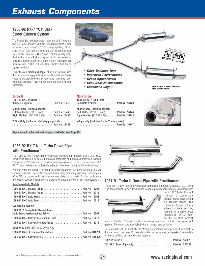
Section
1987-91 Turbo II Down Pipe with Presilencer*The Turbo II Down Pipe and Presilencer combination incorporates a 22” 0.D. Down Pipe and a Power Pulse™ Presilencer to boost power approximately 26 horsepower
on a 1987 Turbo II - and maintain a comfortable exhaust noise level during full throttle driving. The replacement pipe reduces exhaust gas back pressure, resulting in a turbo boost increase of 1-2 PSI, with-out the use of an external
boost controller. This kit contains mounting hardware, split air cover plate, and gaskets. The down pipe is supplied with an oxygen sensor fitting.
Our optional Fuel Cut Controller is strongly recommended to prevent fuel cutoff to the rear rotor (see page 23). We also offer the down pipe (and gaskets) separately for those building custom exhaust systems.
1987-91 Turbo lI . . . . . . . . . . . . . . . . . . . . . . . . . . . . . . . . Part No. 16207
22” O.D. Down Pipe only . . . . . . . . . . . . . . . . . . . . . . . . . Part No. S16207
1986-92 RX-7 Non-Turbo Down Pipe with Presilencer*The 1986-92 RX-7 Down Pipe/Presilencer combination incorporates a 22” O.D. Down Pipe and our perforated stainless steel core and stainless steel wool packed Power Pulse™ Presilencer to boost power approximately 18 horsepower on a 1987 RX-7 - and maintain a comfortable exhaust noise level during full throttle driving.
We also offer the Down Pipe (and gaskets) separately for those building custom exhaust systems. These kits contain all necessary mounting hardware, including an AC & CV (air control and check valve) cover plate, and gaskets. For this application the oxygen sensor is retained in the stock exhaust manifold for correct operation.
Non-Convertible Models
1986-88 RX-7 Manual Trans . . . . . . . . . . . . . . . . . . . . . . . . Part No. 162061989-91 RX-7 Manual Trans . . . . . . . . . . . . . . . . . . . . . . . . Part No. 16213 1986-88 RX-7 Auto Trans . . . . . . . . . . . . . . . . . . . . . . . . . . . Part No. 162081989-91 RX-7 Auto Trans . . . . . . . . . . . . . . . . . . . . . . . . . . . Part No. 16214
Convertible Models
1988 RX-7 Convertible Manual Trans (Auto Trans version not available) . . . . . . . . . . . . . . . . . . . . Part No. 16209
1989-92 RX-7 Convertible Manual Trans . . . . . . . . . . . . . . . . Part No. 16217
1989-92 RX-7 Convertible Auto Trans . . . . . . . . . . . . . . . . . . Part No. 16218
Down Pipe Only -22” O.D. Down Pipe
1986-91 RX-7- Excluding Convertible . . . . . . . . . . . . . . . . . . Part No. S16206
1988-92 RX-7 Convertible . . . . . . . . . . . . . . . . . . . . . . . . . . Part No. S16209
24 www.racingbeat.com
Exhaust Components
1986-92 RX-7 “Cat Back” Street Exhaust SystemThe Racing Beat exhaust system consists of a Y-pipe and two (2) Power Pulse™ Mufflers. The replacement Y-pipe is manufactured using 22” O.D. tubing, splitting off into a pair of 2” O.D. tubes feeding the 304-series stainless steel muffler canisters. The Y-pipe is dimensionally iden-tical to the factory Turbo II Y-pipe and is best suited to replace a failing stock unit. Both muffler canisters are finished with 3” O.D. polished 304 stainless tips for an aggressive look.
This 50-state emissions legal, “bolt-on” system uses the stock mounting points for ease of installation. These systems are supplied with all necessary mounting hard-ware and gaskets. These components are also available separately.
Non-Turbo 1986-92 RX-7 (Non-turbo) Complete System . . . . . . . . . . . . . Part No. 16420
Muffler only (includes gasket) Left Muffler (2” O.D. Inlet) . . . . . . . Part No. 16444 Right Muffler (2” O.D. Inlet) . . . . . . Part No. 16443
Y-Pipe only (includes Cat-to-Y-pipe gasket) . . . . . . . . . . . . . . . . . . . . . . . . . . Part No. 16447
STREET LEGAL
EMISSIONS LEGALNOISE LEVEL CERTIFIED
Turbo II 1987-91 RX-7 (TURBO II) Complete System . . . . . . . . . . . . . Part No. 16418
Muffler Only (includes gasket) Left Muffler (2a” O.D. Inlet) . . . . . . Part No. 16446 Right Muffler (2a” O.D. Inlet) . . . . Part No. 16445
Y-Pipe Only (includes cat-to-Y-pipe gasket) . . . . . . . . . . . . . . . . . . . . . . . . . . Part No. 16447
Replacement rubber exhaust hangers available, see Page 25.
• Deep Exhaust Tone • Improved Performance• Great Appearance!• Easy Bolt-On Assembly• Emissions Legal!
* Legal in California only for racing vehicles which may never be used upon a highway.
Each Muffler Is 100% Stainless Steel Construction!
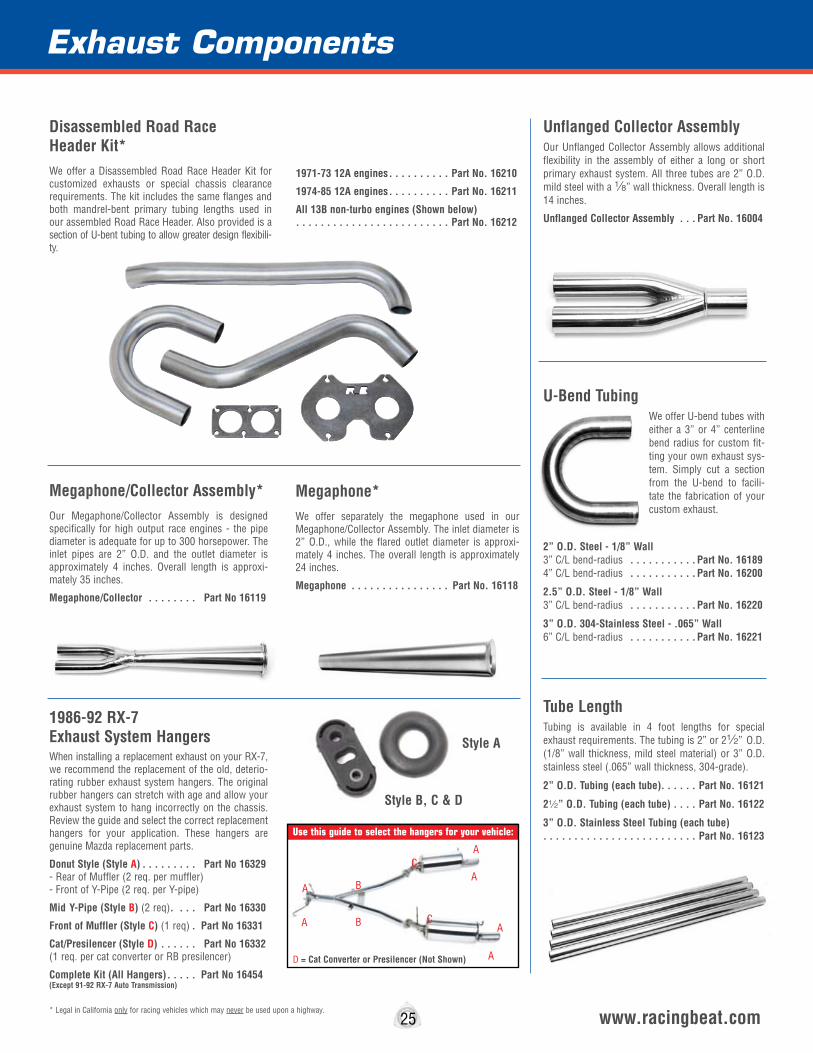
25 www.racingbeat.com
Megaphone/Collector Assembly*Our Megaphone/Collector Assembly is designed specifically for high output race engines - the pipe diameter is adequate for up to 300 horsepower. The inlet pipes are 2” O.D. and the outlet diameter is approximately 4 inches. Overall length is approxi-mately 35 inches.
Megaphone/Collector . . . . . . . . Part No 16119
1986-92 RX-7 Exhaust System HangersWhen installing a replacement exhaust on your RX-7, we recommend the replacement of the old, deterio-rating rubber exhaust system hangers. The original rubber hangers can stretch with age and allow your exhaust system to hang incorrectly on the chassis. Review the guide and select the correct replacement hangers for your application. These hangers are genuine Mazda replacement parts.
Donut Style (Style A) . . . . . . . . . Part No 16329 - Rear of Muffler (2 req. per muffler) - Front of Y-Pipe (2 req. per Y-pipe)
Mid Y-Pipe (Style B) (2 req). . . . Part No 16330
Front of Muffler (Style C) (1 req) . Part No 16331
Cat/Presilencer (Style D) . . . . . . Part No 16332 (1 req. per cat converter or RB presilencer)
Complete Kit (All Hangers) . . . . . Part No 16454(Except 91-92 RX-7 Auto Transmission)
Disassembled Road Race Header Kit*We offer a Disassembled Road Race Header Kit for customized exhausts or special chassis clearance requirements. The kit includes the same flanges and both mandrel-bent primary tubing lengths used in our assembled Road Race Header. Also provided is a section of U-bent tubing to allow greater design flexibili-ty.
1971-73 12A engines . . . . . . . . . . Part No. 16210
1974-85 12A engines . . . . . . . . . . Part No. 16211
All 13B non-turbo engines (Shown below) . . . . . . . . . . . . . . . . . . . . . . . . . Part No. 16212
Unflanged Collector AssemblyOur Unflanged Collector Assembly allows additional flexibility in the assembly of either a long or short primary exhaust system. All three tubes are 2” O.D. mild steel with a 8” wall thickness. Overall length is 14 inches.
Unflanged Collector Assembly . . . Part No. 16004
U-Bend TubingWe offer U-bend tubes with either a 3” or 4” centerline bend radius for custom fit-ting your own exhaust sys-tem. Simply cut a section from the U-bend to facili-tate the fabrication of your custom exhaust.
2” O.D. Steel - 1/8” Wall 3” C/L bend-radius . . . . . . . . . . . Part No. 16189 4” C/L bend-radius . . . . . . . . . . . Part No. 16200
2.5” O.D. Steel - 1/8” Wall 3” C/L bend-radius . . . . . . . . . . . Part No. 16220
3” O.D. 304-Stainless Steel - .065” Wall 6” C/L bend-radius . . . . . . . . . . . Part No. 16221
Tube LengthTubing is available in 4 foot lengths for special exhaust requirements. The tubing is 2” or 22” O.D. (1/8” wall thickness, mild steel material) or 3” O.D. stainless steel (.065” wall thickness, 304-grade).
2” O.D. Tubing (each tube). . . . . . Part No. 16121
22” O.D. Tubing (each tube) . . . . Part No. 16122
3” O.D. Stainless Steel Tubing (each tube) . . . . . . . . . . . . . . . . . . . . . . . . . Part No. 16123
* Legal in California only for racing vehicles which may never be used upon a highway.
Exhaust Components
Megaphone*We offer separately the megaphone used in our Megaphone/Collector Assembly. The inlet diameter is 2” O.D., while the flared outlet diameter is approxi-mately 4 inches. The overall length is approximately 24 inches.
Megaphone . . . . . . . . . . . . . . . . Part No. 16118
B
B C
C
D = Cat Converter or Presilencer (Not Shown)
A
AA
A A
A
Style B, C & D
Style A
Use this guide to select the hangers for your vehicle:
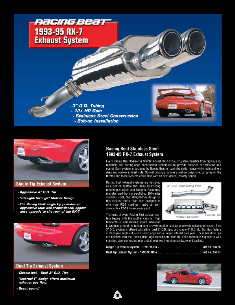
- 3” O.D. Tubing - 12+ HP Gain - Stainless Steel Construction - Bolt-on Installation
Single Tip Exhaust System
Dual Tip Exhaust System
Racing Beat Stainless Steel 1993-95 RX-7 Exhaust SystemEvery Racing Beat 304-series Stainless Steel RX-7 Exhaust System benefits from high-quality materials and cutting-edge construction techniques to provide superior performance and sound. Each system is designed by Racing Beat to maximize performance while maintaining a deep and mellow exhaust note. Normal driving produces a mellow deep tone, but jump on the throttle and these systems come alive with an even deeper, throaty sound.
Racing Beat exhaust systems are designed as a bolt-on system and utilize all existing mounting brackets and hangers. Beautifully manufactured from pre-polished 304-series stainless steel, the straight-thru design of this exhaust muffler has been designed to offer your RX-7 maximum turbo perform-ance with a 12-13 horsepower gain!
The heart of every Racing Beat exhaust sys-tem begins with the muffler canister. High temperature, compressed sound insulation is wrapped around the tubing core of every muffler canister to provide noise suppression. This 3” O.D. system is offered with either dual 3” O.D. tips, or a single 4” O.D. tip. Our tips feature a 70-degree angle cut with a rolled edge and a unique internal core pipe. These beautiful tips are finished with the Racing Beat logo etched onto each tip. Each system is supplied a with stainless steel connecting pipe and all required mounting hardware and gaskets.
Single Tip Exhaust System - 1993-95 RX-7 . . . . . . . . . . . . . . . . . . . . . . . Part No. 16426
Dual Tip Exhaust System - 1993-95 RX-7 . . . . . . . . . . . . . . . . . . . . . . . . Part No. 16427
- Aggressive 4” O.D. Tip
- “Straight-Through” Muffler Design
- The Racing Beat single tip provides an aggressive (but well-proportioned) appear -- ance upgrade to the rear of the RX-7.
- Classic look - Dual 3” O.D. Tips
- “Internal-Y” design offers maximum exhaust gas flow.
- Great sound!
3” O.D. Connecting Pipe
Single TipMuffler Canister
26

www.racingbeat.com
- 3” O.D. Inlet Tubing - 3-4 HP Gain - Stainless Steel Construction - Bolt-on Installation - Aggressive & Exotic Exhaust Tone!
Racing Beat REV8 RX-8 Exhaust SystemThe Racing Beat REV8 street-legal, cat-back exhaust system is the perfect replacement bolt-on system for your stock RX-8 exhaust - a durable assembly offering a real horsepower gain over your stock unit. Our system consists of a 304-series stainless steel Racing Beat connecting-pipe, muffler canister, tubing, flanges, and outlet tips. The replacement connecting-pipe is manufactured using 3” O.D. tubing and features cast stainless steel flanges for positive exhaust gas sealing. The stainless steel muffler canisters are finished with 4” O.D. polished 304 stain-less tips for an aggressive look.
Utilizing our in-house dyno test facilities, Racing Beat’s design team spent considerable effort to fine-tune the internal canister design of our muffler canister to provide what we believe is the ultimate rotary exhaust note! During development of the exhaust, we worked extensively to find the optimum balance between power and sound level. Too much sound dampening would rob power; too little damp-ening would bring the exhaust note up to unacceptable levels.
Just what is “unacceptable”? We assumed that an individual that has purchased a RX-8 is seeking an exhaust note that reflects the character of both the car and the maturity of the car owner. The exhaust note that we envision for this car should provide a modest sound level increase over stock, but any harsh or “tinny” tones should be suppressed. Cruising speeds should not produce any droning or buzzing tones, but provide a deep melodic tone that doesn’t distract from the driving experience. But, jump on the throttle and the exhaust should come alive with an aggressive note that enhances the driving experience. Refined and modest while cruising; aggressive and authoritative under acceleration!
REV8 Exhaust System - 2004-08 RX-8 . . . . . . . . . . . . . . . . . . . . . . Part No. 16397 REV8 Exhaust System - 2009-11 RX-8 . . . . . . . . . . . . . . . . . . . . . . Part No. 16394
* Measured on an otherwise stock RX-8. Sound may vary with additionally installed racing components.
RX-8 Race Exhaust SystemThe Racing Beat Race Exhaust System for the RX-8 is designed to offer a substantial weight savings over the stock exhaust system and conform to a 92 decibel sound level limit.* The single outlet tip is angled downward to further deflect the exhaust note. (The exhaust outlet does not extend through the opening in the rear bumper.) As compared to the stock system (39 lbs), the RB Race System (26 lbs) offers a 13 lb. weight reduction. Although the sound output is notably louder than the stock system, particularly under full throttle, this system can be used for daily “street” driving for those that desire an exhaust that produces a louder, more exotic and aggressive exhaust note. The Race Exhaust System is manufactured using 304-stainless steel and is supplied with a connecting pipe section, hanger extension bracket, mounting hardware, and installation instructions.
Race Exhaust System - 2004-11 RX-8 . . . . . . . . . . . . . . . . . . . . . . . . Part No. 16396
Race Exhaust System
33% Lighter Than the Stock System
Downward Angled Single Outlet Tip
3” O.D. Stainless Steel Connecting Pipe
Stainless Steel Outlet Tips
Stainless Steel Flanges & Hangers
100% Stainless Steel Mufflers
RX-8PRODUCT
27
RX-8PRODUCT

Exhaust Components
Engine to Header1974-85 (12A) AA 1618213B (Steel Flange) AA 1618313B (Stainless Steel Flange) AA 1618720B (3-rotor) BB 16184Renesis 13B LL 16169MFR Peripheral Port Exhaust Flange N/A 16201
Road/Race HeaderRoad/Race Header Outlet Flange JJ 16197
Turbo Outlet1987-91 TURBO II CC 16180
Heat Exchanger1976-80 Front FF 16199
PreSilencer1979-80 “Mini” Front FF 161991979-80 “Mini” Rear EE 161951981-83 Front/Rear (12mm studs) EE 161951984-85 Front/Rear (10mm studs) EE 161901986-92 (All models) Except Part No 16425P HH 16177
6-Port Sensing Tube 1984-88 (6 Port) DD 16324
Muffler 1971-80 (Donut style) GG 161931981-82 (Dual tube style) II 161881983-85 (Single tube style) EE 16195
Custom Application FlangesMulti-Purpose Flange (2-inch) EE 161953” ID Flange - Stainless Steel (requires gasket 16340) KK 16185
Flange Type Photo Part No.
AA
BBCC
DD
EE
KK
LL
FF
GG
HH
II
JJ
28 www.racingbeat.com
Part No.
A B
C
DO
N
F
G HI
J
KL
M
The following charts can be used to identify replacement gaskets and flanges for Racing Beat exhaust components. If you have a question regard-ing the correct gasket or flange for your application, contact Racing Beat.
*Note: REV-TII Exhaust System individual components gaskets - see page 23.
Engine to Header1971-73 (2 required) A 163011974-75 (2 required) B 163021976-85 (12A) C 163051976-78 (13B) C 163061984-92 (13B, Non-turbo) C 1630920B (2 needed -Cutting required) C 16309Renesis (13B) N 16304
Road/Race HeaderOutlet Gasket M 16300
Turbo Outlet1987-91 Turbo II D 16319
Down Pipe*1986-92 Non-turbo (front & rear) G 16318 1987-91 Turbo II (rear) G 16318 Heat Exchanger1976-80 Front F 163101976-80 Rear F 16311
6-Port Sensing Tube 1984-88 (6-Port) J 16316 “Cat” Replacement Pipe1981-83 Front F 16315 Rear F 163151984-85 Front F 16315 Rear I 16313
PreSilencer*1979-80 “Mini” Front F 16310 Rear F 163151981-83 Front/Rear (12mm studs) F 163151984-85 Front/Rear (10mm studs) F 163111986-92 Front/Rear G 16318
Y-Pipe*1986-92 (front) F 16318
Muffler* 1979-80 (Donut style) K 163121981-82 (Dual tube style) L 163141983-85 (Single tube style) I 163151986-92 (Turbo & non-turbo) I 163131993-95 (Muffler & Connecting Pipe- Front) H 16340REV8 RX-8 Muffler (Muffler) O 16343
Custom Application GasketsMulti Purpose gasket (for flange 16195) F 16315
FlangesGaskets
Gasket Type Photo
Oxygen Sensor FittingsThis fitting can be installed on your custom exhaust system to aid in the placement of an oxygen sensor.
Stainless Steel . . . . . . . . . . . . . . . . . . . . . Part No. 95420
Steel Fitting . . . . . . . . . . . . . . . . . . . . . . . Part No. 95422
Sensor PlugThis fitting can be used to plug a sensor fitting as required.
Stainless Steel . . . . . . . . . . . . . . . . . . . . . Part No. 56014
Laser Cut Flanges
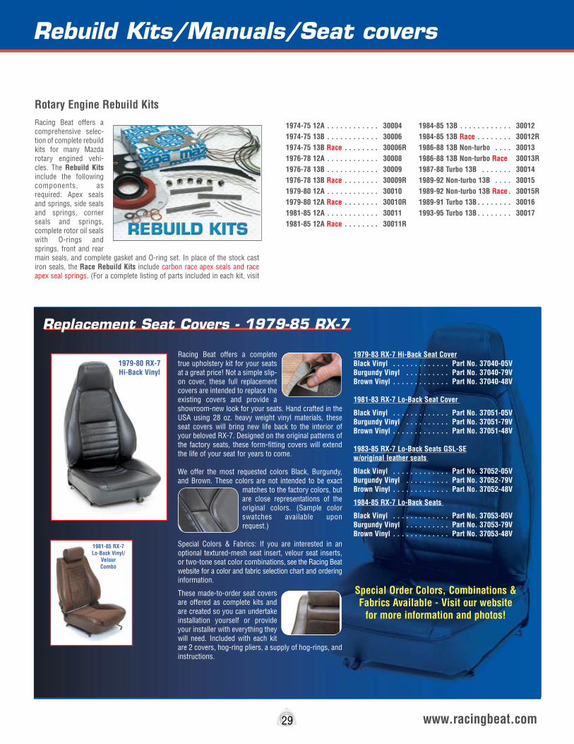
Rebuild Kits/Manuals/Seat covers
29 www.racingbeat.com
1974-75 12A . . . . . . . . . . . . 300041974-75 13B . . . . . . . . . . . . 300061974-75 13B Race . . . . . . . . 30006R1976-78 12A . . . . . . . . . . . . 300081976-78 13B . . . . . . . . . . . . 300091976-78 13B Race . . . . . . . . 30009R1979-80 12A . . . . . . . . . . . . 300101979-80 12A Race . . . . . . . . 30010R1981-85 12A . . . . . . . . . . . . 300111981-85 12A Race . . . . . . . . 30011R
1984-85 13B . . . . . . . . . . . . 300121984-85 13B Race . . . . . . . . 30012R1986-88 13B Non-turbo . . . . 300131986-88 13B Non-turbo Race 30013R1987-88 Turbo 13B . . . . . . . 300141989-92 Non-turbo 13B . . . . 300151989-92 Non-turbo 13B Race. 30015R1989-91 Turbo 13B . . . . . . . . 300161993-95 Turbo 13B . . . . . . . . 30017
Rotary Engine Rebuild KitsRacing Beat offers a comprehensive selec-tion of complete rebuild kits for many Mazda rotary engined vehi-cles. The Rebuild Kits include the following components, as required: Apex seals and springs, side seals and springs, corner seals and springs, complete rotor oil seals with O-rings and springs, front and rear main seals, and complete gasket and O-ring set. In place of the stock cast iron seals, the Race Rebuild Kits include carbon race apex seals and race apex seal springs. (For a complete listing of parts included in each kit, visit
Replacement Seat Covers - 1979-85 RX-7
Racing Beat offers a complete true upholstery kit for your seats at a great price! Not a simple slip-on cover, these full replacement covers are intended to replace the existing covers and provide a showroom-new look for your seats. Hand crafted in the USA using 28 oz. heavy weight vinyl materials, these seat covers will bring new life back to the interior of your beloved RX-7. Designed on the original patterns of the factory seats, these form-fitting covers will extend the life of your seat for years to come.
We offer the most requested colors Black, Burgundy, and Brown. These colors are not intended to be exact
matches to the factory colors, but are close representations of the original colors. (Sample color swatches available upon request.)
Special Colors & Fabrics: If you are interested in an optional textured-mesh seat insert, velour seat inserts, or two-tone seat color combinations, see the Racing Beat website for a color and fabric selection chart and ordering information.
These made-to-order seat covers are offered as complete kits and are created so you can undertake installation yourself or provide your installer with everything they will need. Included with each kit are 2 covers, hog-ring pliers, a supply of hog-rings, and instructions.
1979-83 RX-7 Hi-Back Seat CoverBlack Vinyl . . . . . . . . . . . . . Part No. 37040-05V Burgundy Vinyl . . . . . . . . . . Part No. 37040-79V Brown Vinyl . . . . . . . . . . . . . Part No. 37040-48V
1981-83 RX-7 Lo-Back Seat Cover
Black Vinyl . . . . . . . . . . . . . Part No. 37051-05VBurgundy Vinyl . . . . . . . . . . Part No. 37051-79V Brown Vinyl . . . . . . . . . . . . . Part No. 37051-48V
1983-85 RX-7 Lo-Back Seats GSL-SE w/original leather seats
Black Vinyl . . . . . . . . . . . . . Part No. 37052-05V Burgundy Vinyl . . . . . . . . . . Part No. 37052-79VBrown Vinyl . . . . . . . . . . . . . Part No. 37052-48V
1984-85 RX-7 Lo-Back Seats
Black Vinyl . . . . . . . . . . . . . Part No. 37053-05V Burgundy Vinyl . . . . . . . . . . Part No. 37053-79VBrown Vinyl . . . . . . . . . . . . . Part No. 37053-48V
Special Order Colors, Combinations & Fabrics Available - Visit our website
for more information and photos!
1981-85 RX-7Lo-Back Vinyl/
Velour Combo
1979-80 RX-7Hi-Back Vinyl
Ignition TipsThere are few areas on an automobile that are as subject to misinformation and misunderstanding as the ignition - largely because there are so many choices available. Another reason is that, in spite of many manufacturers’ best intentions, ignition systems seem to fail much too often.
To begin, we should establish that the stock ignition system on most rotaries is reasonably good. The big-gest fault with all rotaries before 1980 is that the points in the system require constant maintenance: beginning in 1980, Mazda introduced a breakerless distributor eliminating that problem.
Ignition Systems
There are two general types of ignition systems: “coil storage” (reactor) systems that build up a magnetic field in a coil, then discharge it as high voltage across the spark plugs, and “capacitative discharge” (trans-former) systems that build up a charge on a capaci-tor, then discharge the capacitor through a coiI (transformer) that induces a large voltage across the spark plug. In general terms, “coil storage” systems are capable of less peak voltage than “capacitive discharge” systems, but have longer “sparking” (burn) time. Our tests have shown that both burn time and maximum voltage capability are important, so neither system is necessarily better.
There are two general types of ignition triggers: breaker points and “breakerless.” “Breakerless” style ignition triggers include magnetic induction (Mazda 1980 and later), photoelectric, and “Hall Effect Cells.” Any type of theses triggers can be designed to work with either type of ignition system.
Although a well-designed, point triggered coil storage ignition (stock on all Mazdas before 1980) will make almost as much power as the best ignitions available under optimal conditions, the fact that points deterio-rate so quickly and that this style of ignition has little reserve energy capacity make it a poor choice for high performance or racing use.
As stated, Mazda began equipping their rotary engines with “breakerless” ignitions in 1980. With the 1980 model RX-7 the electronic components were located in a separate box, while the 1981-85 RX-7 models’ electronics were mounted on the distributor housing. Aside from simplifying the ignition, this change has eliminated a major problem we have seen in the 1980 ignition system - a tendency to “cross trigger” between the leading and trailing ignitions.
“Cross-Triggering” Diagnosis
This cross-triggering, which occurs randomly, causes the trailing ignition to fire at the same time as the
leading ignition. The result is very dangerous to the engine at higher power output.
Cross-triggering is a very common problem with “aftermarket” ignitions used on rotary engines. The problem arises because Mazda's rotaries have two complete ignition systems that normally do not fire at the same time, while virtually all the other cars in the world either have only one ignition or, if they have dual ignition, the ignitions fire at the same time. This problem can be observed with a timing light con-nected to the trailing ignition, and will show up as a variation in timing, occasionally switching between the leading and trailing timing settings.
Distributor Upgrades
If you wish to install the 1981-85 RX-7 breakerless distributor in a stock 1974-79 engine, there is one potential problem: the centrifugal and vacuum advance characteristics of this distributor are slightly different from the original equipment “breaker point” style distributors. The easiest way to deal with this is to set the timing to: Leading - 24° BTC / Trailing - 14° BTC at 5,000 RPM and use this as a starting point (vacuum disconnected). If you wish to use this dis-tributor for racing purposes, the vacuum advance should not be used, and the timing should be set to the proper Total Advance Setting (refer to the Timing Chart on page 31).
Ignition Timing
Timing in some models is fairly insensitive while in others, it is critical. The Timing Chart is based solely on our experience. Since every engine is different, you can expect some variation in what works best, so use this only as a guide. If you hear a “fluttering” in the intake or experience a loss of power after advanc-ing the timing, retard it immediately. Retarding the timing too much will reduce power and mileage and cause the exhaust to run excessively hot, possibly damaging it, but it is unlikely to hurt the engine itself. On the other hand, excessive ignition advance can break apex seals and damage rotor housings.
As a general rule, trailing timing doesn't help the power much, but it is more dangerous than the lead-ing timing to the engine if set incorrectly. When experimenting, advance the leading timing in 2° steps to find the optimum setting, then advance the trailing in 2° steps to find its best position. Finally, retard both 1° or 2° for safety.
Supercharging/Turbo
Supercharged engines deserve special comment. In general, if you are just adding a small amount of boost (low restriction exhaust system), leave the tim-ing at the stock settings. However, if you are porting the engine, running high boost and a large intercooler,
or operating the engine at continuous high RPM, consider retarding the timing a bit. In our peripheral port turbo engines, we use 10° BTC total advance, leading and trailing, for dyno development and 12° BTC total advance for racing, after the engine man-agement fuel mixture is well established. The timing is set at 6000rpm and leading and trailing plugs are fired simultaneously. The truth is that the power increase at 12° BTC is small and the danger is greater than at 10° BTC. Each increment in timing increases the risk for smaller and smaller gains in power.
Tachometer Tips
Since a rotary engine fires each spark plug once per revolution of the eccentric shaft per cylinder, if you use a distributor to trigger an electric tach, a 2-rotor engine has the same firing pulses as a 4-cylinder reciprocating engine and a 3-rotor fires like a 6-cylin-der. However, other combinations are possible. If you attempt to connect a tach to an 1986 and later leading coil, it will still function as explained above, but if you connect to one of the trailing coils, the tach will only see half as many pulses since each trailing coil only fires once per eccentric shaft revolution. Thus, in the case of the trailing coil used as a trigger, the engine fires like a 2-cylinder reciprocating engine for a 2-rotor, or a 3-cylinder reciprocating engine for a 3-rotor.
We have seen instances when the failure of a tachom-eter, when hooked to the leading ignition coil, has caused the leading ignition system to fail as well. For this reason, we suggest you consider wiring the tachometer to the trailing ignition; in the event of a tachometer failure you still have a functioning leading ignition.
Spark Plug Gap/Torque
Virtually all modern stock engines use relatively large plug gaps for good idle and emission purposes. However, as power and RPM increases, large plug gaps require more and more ignition energy to fire reliably. There is no exact relationship, but expect to reduce plug gap as power and RPM increase. In all high output race engines we use a gap of .015”. If the gap erodes to .020” or more, power loss usually occurs.
When using our Racing Beat recommended spark plugs in street applications we find a gap of .020” to be a reasonable compromise. When using the following plugs: BR7EIX, BR8EIX, BR9EIX, and BR10EIX - we recommend a gap of .015”. We recommend that a drop of engine oil be applied to the threads, and using our Thin Wall Spark Plug Socket (See page 32) each plu should be torqued to 15 ft/lbs.
30 www.racingbeat.com

BTC = Degrees Before Top Center (before 0°)ATC = Degrees After Top Center (after 0°)L = Leading Spark PlugT = Trailing Spark PlugWhen attempting to set the ignition timing to a position other than the stock factory setting, you must first identify the marks on the pulley. This can usually be accomplished
by reading the ignition timing decal located on the under-side of the hood. Once you know what each mark means in degrees, you can use a pair of dividers to mark your own settings on the pulley, referenced to the original marks.
Note 1 The Mazda Factory recommends 20° BTC leading and 20° trailing.
Turbo/Supercharged ApplicationsWhen turbocharging or supercharging a 2-rotor engine capable of 300+ horsepower, we recommend both Leading and Trailing timing be set at 10 to 12 degrees total advance, at 6000 rpm, regardless of the porting configuration.
31 www.racingbeat.com
The recommendations in this chart for non-ported and street-ported engines are based on the conven-tional method of setting the timing - at idle, with the vacuum advance disconnected. The recommenda-
tions for bridge ported and peripheral ported engines (shaded values) are maximum advance settings, usu-ally measured by revving the engine to 6,000 RPM. This is essential in race engines, since timing is criti-
cal to life and performance. No vacuum advance is used in racing, and it is common to eliminate the centrifugal advance to avoid an area for failure.
Stock Porting & Intake System
Stock Porting Dell’orto, Holley,
or Weber
Street Porting & Dell’orto,
Holley, or Weber
Bridge Porting (open
exhaust)
Peripheral Porting (open
exhaust)
L 3° BTC
T 5° ATC
L 0°
T 5° ATC
1971-73
12A
1974-75
12A
1976
12A
1977-83
12A
1984-85
12A
1974-75
13B
1976-78
13B
1984-85
13B GSL-SE
1986-92
Non-turbo
L 2° BTC
T 15° ATC
L 2° BTC
T 19° ATC
Stock
Stock
L 0°
T 10° ATC
Stock
Stock
L 2.5° BTC
T 12.5° ATC(w/fuel inject.)
Stock
Stock
L 8° BTC
T 0°
L 2° BTC
T 4° ATC
L 2° BTC
T 15° ATC
L 2° BTC
T 19° ATC
Stock
Stock
L 0°
T 8° ATC
L 3° BTC
T 13° ATC
Stock
Stock
w/ Dell’orto carb
NA
L 8° BTC
T 2° ATC
L 2° BTC
T 6° ATC
L 8° BTC
T 12° ATC
L 8° BTC
T 12° ATC
L 3° BTC
T 17° ATC
L 0°
T 10° ATC
L 0° BTC
T 10° ATC
L 6° BTC
T 6° ATCw/ Weber carb
NA
35°
15°
20°
15°
24°
5°
24°
5°
24°
5°
20°
13°
20°
13°
20°
13°
20°
13°
35°
15°
20°
15°
24°
5°
24°
5°
24°
5°
20°
10°
20°
10°
20°
10°
20°
10°
Shaded values indicate degrees BTC measured at 6,000 rpm.
See Note 1 See Note 1 See Note 1 See Note 1
Timing Recommendations
RX-8 Ignition
The stock, individual coil system on the RX-8 is very good and so far we have not found any advantage from changing it. We tested changes in timing for improved power but found no performance benefit! The fact is that Mazda has pushed the limit of ignition advance, and more (or less) timing advance yields no significant improvement. We have also tested the knock sensor system and found that though it is good,
it can cause minor problems. The sensor seems to detect normal engine vibrations as “knock” (pre-igni-tion), and because if this, the ECU retards the timing. Unbolting the knock sensor from the #2 rotor housing (do not disconnect it electronically - this will cause an ECU fault and retard the timing. ) usually adds a small amount of power (often 1+HP) by eliminating the ran-dom, unnecessary retarding of ignition. Of course, if the engine should experience knock, your unbolted sensor will never know it- but cars ran for many years
without these sensors and survived!
We tested a variety of spark plugs in the RX-8 engine, and found that the stock plug is well-suited for this application. However, for racing applications, we rec-ommend the NGK R6725-10.5 plug at .025”-.032” gap - they make additional power, but they are a very “cold” plug and will foul easily. These plugs can also be used in turbocharged applications.
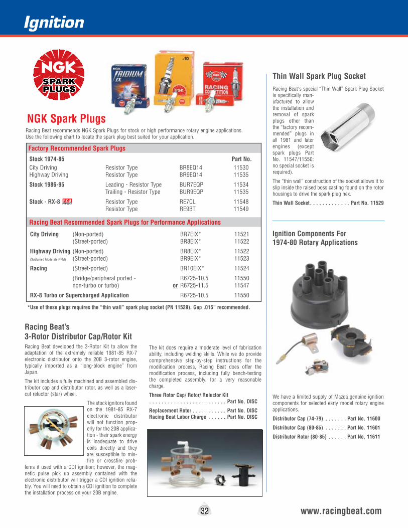
Racing Beat’s 3-Rotor Distributor Cap/Rotor KitRacing Beat developed the 3-Rotor Kit to allow the adaptation of the extremely reliable 1981-85 RX-7 electronic distributor onto the 20B 3-rotor engine, typically imported as a “long-block engine” from Japan.
The kit includes a fully machined and assembled dis-tributor cap and distributor rotor, as well as a laser-cut reluctor (star) wheel.
The stock ignitors found on the 1981-85 RX-7 electronic distributor will not function prop-erly for the 20B applica-tion - their spark energy is inadequate to drive coils directly and they are susceptible to mis-fire or crossfire prob-
lems if used with a CDI ignition; however, the mag-netic pulse pick up assembly contained with the electronic distributor will trigger a CDI ignition relia-bly. You will need to obtain a CDI ignition to complete the installation process on your 20B engine.
The kit does require a moderate level of fabrication ability, including welding skills. While we do provide comprehensive step-by-step instructions for the modification process, Racing Beat does offer the modification process, including fully bench-testing the completed assembly, for a very reasonable charge.
Three Rotor Cap/ Rotor/ Reluctor Kit . . . . . . . . . . . . . . . . . . . . . . . . . Part No. DISC
Replacement Rotor . . . . . . . . . . . Part No. DISC Racing Beat Labor Charge . . . . . . Part No. DISC
Section
32 www.racingbeat.com
Stock 1974-85 Part No.City Driving Resistor Type BR8EQ14 11530 Highway Driving Resistor Type BR9EQ14 11535
Stock 1986-95 Leading - Resistor Type BUR7EQP 11534 Trailing - Resistor Type BUR9EQP 11535
Stock - RX-8 Resistor Type RE7CL 11548 Resistor Type RE9BT 11549
City Driving (Non-ported) BR7EIX* 11521 (Street-ported) BR8EIX* 11522
Highway Driving (Non-ported) BR8EIX* 11522 (Sustained Moderate RPM) (Street-ported) BR9EIX* 11523
Racing (Street-ported) BR10EIX* 11524
(Bridge/peripheral ported - R6725-10.5 11550 non-turbo or turbo) or R6725-11.5 11547
RX-8 Turbo or Supercharged Application R6725-10.5 11550
Factory Recommended Spark Plugs
Racing Beat Recommended Spark Plugs for Performance Applications
Thin Wall Spark Plug SocketRacing Beat's special “Thin Wall” Spark Plug Socket is specifically man-ufactured to allow the installation and removal of spark plugs other than the “factory recom-mended” plugs in all 1981 and later engines (except spark plugs Part No. 11547/11550: no special socket is required).
The “thin wall” construction of the socket allows it to slip inside the raised boss casting found on the rotor housings to drive the spark plug hex.
Thin Wall Socket . . . . . . . . . . . . . Part No. 11529
We have a limited supply of Mazda genuine ignition components for selected early model rotary engine applications.
Distributor Cap (74-79) . . . . . . . Part No. 11600
Distributor Cap (80-85) . . . . . . . Part No. 11601
Distributor Rotor (80-85) . . . . . . Part No. 11611
Racing Beat recommends NGK Spark Plugs for stock or high performance rotary engine applications. Use the following chart to locate the spark plug best suited for your application.
NGK Spark Plugs
Ignition
*Use of these plugs requires the “thin wall” spark plug socket (PN 11529). Gap .015” recommended.
Ignition Components For 1974-80 Rotary Applications
RX-8PRODUCT

STREET WIRE SETS 1971-85 (6000 Ohm Resistance) . . . . .Part No. 115171971-85 (w/ shields) (5000 Ohm) . .Part No. 115181986-92 (5000 Ohm) . . . . . . . . . . .Part No. 115191987-91 Turbo II (5000 Ohm) . . . . .Part No. 115151993-95 (5000 Ohm) . . . . . . . . . . .Part No. 115102004-11 RX-8 (2000 Ohm) . . .Part No. 11516
RACE WIRE SETS1971-85 All (1000 Ohm Resistance) . .Part No. 115131986-92 Non-turbo (0 Ohm) . . . . . .Part No. 115141987-91 Turbo II (0 Ohm) . . . . . . .Part No. 115201993-95 (0 Ohm) . . . . . . . . . . . . .Part No. 11511
RX-8PRODUCT
8mm Silicone Ignition WiresRacing Beat’s ULTRA 8mm wire sets are constructed with zinc-plated high-strength copper wire to improve durability and prevent corrosion. Threaded brass con-nectors are crimped to all wire ends to provide a supe-rior connection. The silicone rubber used will handle over 100,000 volts and is capable of withstanding tem-perature ranges from -60°F to +480°F over exception-ally long periods. To reduce electromagnetic radiation, ULTRA Ignition wire sets have a wire wound resistor encapsulated in each spark plug boot.
We offer ULTRA Ignition Wire sets for both street and race rotary applications. Street wire sets combine excel-lent radio noise suppression with high performance (5000- 6000 Ω) while the race provides lower resistance (0-1000 Ω), with substantial radio interference.
To obtain reasonable horsepower gains while curbing radio interference from your ignition system, we recom-mend the use of resistor spark plugs with our ULTRA 8mm Street Ignition Wires. To obtain maximum power gains from our ULTRA 8mm Race Ignition Wires, we recommend the use of non-resistor spark plugs.
NOTE: Some aftermarket “performance” spark plugs have proven to be unacceptable in terms of manufactur-ing quality; specifically, these plugs develop compres-sion leaks between the porcelain and steel subcompo-nents causing both premature spark plug boot failure and genuine horsepower losses. For this reason, we strongly encourage the use of the factory or Racing Beat’s recommended spark plugs only for use with our wire sets.
Section
8mm Silicone Ignition Wires
Fiberglass Braid “Sandwiched” Between Silicone Rubber Layers for Added Tensile and Torsional Strength.
ULTRA boots seal tightly at all connection points - spark plugs, ignition coils, and the wires themselves - to positively exclude moisture under the most demanding conditions. Each boot features a crimped, threaded connection for optimum electrical connection.
33
“Screw-Together” Connection
“Wire-Wound” Carbon Resistor
Spring Steel Retaining Clip
Water-Tight Seal
Silicon Rubber Insulation Boot
Finned Brass Terminal
Fiberglass Braid for Added Tensile Strength
The Best Ignition Wire Set You’ll Ever Own For Your Rotary Mazda!
www.racingbeat.com
Ignition

Engine Internal Component TipsWhen increasing the power output of the rotary engine, there comes a point when bolting on an intake system and an exhaust system, combined with other external modifications, are simply not enough. Further horsepower gains require higher engine RPM operat-ing levels which necessitate a number of internal engine component modifications and replacements.
The suggestions presented below are based on Racing Beat’s three decades of developing high per-formance rotary engine components, as well as tips gathered from other racers and the Mazda Factory.
We recommend that when rebuilding an engine that is stock in every respect, you should use only parts intended for the year engine you are rebuilding. However, if your goal is to build a high performance engine, Racing Beat offers a wide variety of compo-nent upgrades.
Apex Seals
From its introduction in the United States in 1970 through the 2006 production year, Mazda’s rotary engines have incorporated three different apex seal thicknesses:
• 1971-1973 -5mm aluminum-filled carbon seals • 1974-85 - 3mm cast iron seals •1986-95 & RX-8 Renesis - 2mm cast iron seals.
While the thickness of the apex seals has decreased over the years, the overall reliability and compression sealing capabilities of these thinner seals was not sacrificed. 1986 and later engines - both turbo and non-turbo versions - utilize the thinnest (2mm) seals and produce the greatest horsepower.
Furthermore, we do not recommend attempting to retro-fit the 3mm apex seals (1974-85 type) into the later (1986-95) rotors, typically accomplished by machining the apex seal grooves - performance will not be improved and overall reliability will likely decrease.
There are three (3) common types of apex seals for 1974-95 engines: Cast iron (stock), aluminum-filled carbon, and ceramic. Your selection will depend on many factors, including; RPM range, normally aspi-rated or supercharged, acceptable wear rates, and cost. (Note: In this technical manual/catalog, super-charged means either “turbocharged” or “mechani-cally supercharged”.)
Cast Iron (stock) apex seals are best for many applications. As long as you never exceed 8,500 RPM (RX-8 -9500 RPM) and don’t run the engine highly supercharged (not exceeding 12 psi of boost), the stock seals will “seal” better and last a long time. When building a high performance engine, run the latest model apex seal/rotor housing combination suit-able for your series of engine.
Aluminum-filled Carbon seals are well suited to high RPM, normally aspirated engines. They are mod-erate in price and are very reliable. They do not seal as well as the multi-piece cast iron seals - especially at low RPM - but this is not very important in the 8,500 to 10,000 RPM range. The fact that they are the light-est seal available allows the carbon seals to stay on the rotor housing surface very well at high RPM. We do not recommend carbon seals for use in turbo applications, because we believe they are too fragile in the event of detonation.
Ceramic apex seals were originally developed by Mazda for competition use. These seals have several advantages over carbon seals: they are stronger in tensile strength, they have an extremely hard, shiny surface which reduces friction, and they do not grow as much in size with increasing temperature as do carbon seals (this allows tighter fitting clearances and less gas leakage); however, there are some disadvan-tages: they are not as light as carbon seals and they are much more expensive. They also can be broken by detonation, particularly in turbo engines.
Apex Seal Clearances
We urge you to pay close attention to the apex seal groove and length clearance as specified in the follow-ing chart:
The groove clearance (∆G) is measured with a feeler gauge inserted between the seal and groove. The key concerns are that the clearance is correct and uniform across the full length of the seal. If not, either the seal must be sanded (using 400 or 600 grit wet-or-dry sandpaper on a flat surface such as a piece of glass), or you must sand the rotor groove with strips of the same sandpaper wrapped over a putty knife blade which is held flat against one side of the rotor groove. The end clearance (∆S) is determined by measuring at least eight (8) rotor housing thickness dimensions (near the inner surface of the rotor housing, at loca-tions evenly distributed around the housing), selecting the smallest dimension, and subtracting the apex seal length from it.
Apex Seal Spring Selection
Apex seal spring selection is generally easy - just use the seal springs recommended for the apex seals you have selected. The dual apex seal springs Mazda used on 1986 and later stock seals appear to be a real advance for the stock (and heavy) cast iron seals, but this arrangement is less critical with the carbon or ceramic seals. However, for engines running high boost or extreme RPM, dual springs are beneficial.
When assessing apex seal wear upon disassembly, it is wise to note the following points. If the sides of the apex seal and the groove show damage and/or the apex seal spring has lost its tension it is likely that the rotor was inadequately cooled. Either insufficient oil was sprayed inside the rotor from the eccentric shaft or excessive heat was put into the seal, possibly due to too much timing advance or high turbo boost. If the curved, sliding surface of the seal is scarred or chipped, it is likely that the rotor housing surface was too hot. This can be remedied by reducing the coolant temperature, increasing the water flow rate, eliminat-ing water pump cavitation and improving the heat conductivity of the rotor housings (see rotor housing section).
Corner Seals
Corner seals play an important role in the low-RPM operation of a rotary engine. Their role becomes critical in hot-start performance. In general, the tighter these seals fit, the better, up to the point where they are actu-ally binding in the corner seal recess against their own spring force. The rubber corner seal plug mounted in some corner seals further reduces low-RPM compres-sion leakage. The benefit of the rubber corner seal plugs in racing engines is small, at best. Always use new corner seals and corner seal plugs when rebuilding an engine.
Starting in 1993, Mazda offered a stronger corner seal spring made from stamped steel instead of wire. The later spring seems to improve sealing in supercharged engines, but benefits on normally aspirated engines are difficult to measure. These springs can be retrofit-ted to the 1992 and earlier engines.
Side Seals
The side seal-to-corner seal end clearance should be .0015” to .0040” when using new side seals and .0070” maximum when re-installing used side seals with new corner seals. Handle side seals gently and if re-installing used seals be sure to return them to their original fitted positions you recorded when you disas-sembled the engine.
RX-8 Note: It is very difficult to measure this clearance in an RX-8 engine due to the taper on the outside of the seal. Side seals should be selected as Mazda rec-ommends - by using the code stamped on the rotors.
Seal Type ∆G ∆S
34 www.racingbeat.com
CAST IRON
Stock .0020 to .0035 See Factory Performance .0030 to .0040 Specifications
CARBON
Normally Aspirated (Race) .0035 to .0040 .0045 to .0055
CERAMIC
Normally Aspirated .0010 to .0015 .0015 to .0020 Supercharged/Turbo .0015 to .0020 .0015 to .0020
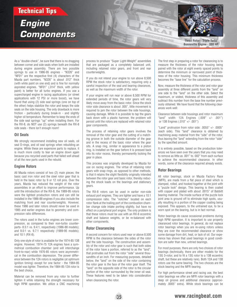
35 www.racingbeat.com
As a “double-check”, be sure that there is no dragging between corner and side seals when both are installed during engine assembly. There are two possible springs to use in 1986-95 engines - “N326” and “NF01” are the respective first (4) characters of the Mazda part numbers. “N326” is about .012” thick (with white paint on one end) and is fine for normally aspirated engines. “NF01” (.014” thick, with yellow paint) is better for all turbo engines. If you use a supercharged engine in racing applications (or street applications with 12 PSI or more boost), we have found that using (2) side seal springs (one on top of the other) helps stabilize the rotor and keeps the side seals on the side housing. The only drawback is more friction - particularly during break-in - and slightly higher oil temperature. Remember to keep the ends of the side seal springs “up” when installing them. For the RX-8, do NOT use (2) springs beneath the RX-8 side seals - there isn’t enough room!
Oil Seals
We strongly recommend installing new oil seals, oil seal O-rings, and oil seal springs when rebuilding an engine. While these are expensive parts to replace, it is much more costly to tear an engine down again because you recycled used parts that failed well ahead of all the new parts used in the rebuild.
Engine Rotors
All Mazda rotors consist of two (2) main pieces: the basic cast iron rotor and the steel rotor gear that is held in the basic rotor by 9 or 12 roll pins. Over the years, Mazda has reduced the weight of the rotor assemblies in an effort to improve performance. Up until the introduction of the RX-8, the 1989-95 rotors were the lightest production rotors and can still be installed in the 1986-88 engines if you also include the matching front and rear counterweights. However, these 1986 and later rotors should never be used in 1985 and earlier engines due to geometry and com-pression ratio differences.
The rotors used in the turbo engines are lower com-pression, as compared to their non-turbo counter-parts- 8.5:1 vs. 9.4:1, respectively (1986-88 models); and 9.0:1 vs. 9.7:1 respectively (1989-95 models); and 10:1 (RX-8).
Only one style of rotor is available for the 1974-85 13B engine. However, 1974-75 12A engines have a sym-metrical combustion chamber (and will interchange front-to-rear) while 1976-85 rotors were asymmetri-cal in the combustion depression. The power differ-ence between the 12A rotors is negligible (at optimum ignition timing) except for one factor - the 1984-85 model was lighter. Therefore, the 1984-85 12A rotor is the best choice.
Material can be removed from any rotor to further lighten it while retaining the strength necessary for high RPM operation. We utilize a CNC machining
process to produce “Super Light-Weight” assemblies that are packaged as a completely balanced unit, including retained rotor gears, and front and rear counterweights.
If you do not intend your engine to run above 8,500 RPM the stock rotor is satisfactory, requiring only a careful inspection of the seal and bearing clearances, as well as the maximum width of the rotor.
If your engine will run near or above 8,500 RPM for extended periods of time, the rotor gears will very likely move away from the basic rotor. Since the stock rotor side clearance is about .005”, little movement is required to jam the rotor between the side housings, causing damage. While it is possible to tap the gears back down with a plastic hammer, the problem will persist until the rotors are replaced with retained rotor gear components.
The process of retaining rotor gears involves the removal of the rotor gear and the cutting of a match-ing groove in both the outside diameter of the gear and in the recess of the basic rotor where the gear sits. A snap ring, similar in appearance to a piston ring, is installed on the gear before it is pressed back into its rotor recess, thereby permanently locking the gear in place.
This process was originally developed by Mazda for use on racing engines. The virtue of retaining rotor gears with snap rings, as opposed to other methods, is that it retains the slight flexibility originally intended between the rotor gear and basic rotor, thereby reduc-ing the shock loads on the bearings and stationary gears.
The RX-8 rotors can be used in earlier non-side exhaust port engines. They are lighter and have a 10:1 compression ratio. The “notches” located on each rotor flank at the trailing port of the combustion cham-ber change side intake porting slightly, but have no effect on a peripheral port engine. The only problem is that these rotors must be use with an RX-8 eccentric shaft and balance weights, or be re-balanced with other components.
Rotor Clearancing
A second concern for rotors used near or above 8,500 RPM is the clearance between the sides of the rotor and the side housings. The construction and assem-bly of the rotor and rotor gear is such that both sides of the rotor have a portion, referred to as the “land”, that protrudes out from the rotor “side” several thou-sandths of an inch. For measuring purposes, detailed below, the “land” on the side of the rotor containing the rotor gear is the face of the rotor gear itself. The “land” on the opposite side of the rotor is the circular portion of the rotor surrounded by the inner oil seal. These features need to be taken into consideration when clearancing the rotor.
The first step in preparing a rotor for clearancing is to measure the thickness of the rotor housing being paired with the rotor at eight evenly spaced points to determine the minimum or narrowest point of thick-ness of the rotor housing. This minimum thickness becomes the “base line” for the calculation process.
Now, measure the thickness of the rotor and rotor gear assembly at three different points from the “land” on one side to the “land” on the other side. Select the maximum, or widest, thickness of this assembly and subtract this number from the base line number previ-ously obtained. We have found that the following clear-ances work well:
Clearance between side housings and rotor maximum “land” width: 12A Engines (.009” +/- .001”) or 13B Engines (.010” +/- .001”)
“Land” protrusion from rotor side: .0055” +/- .0005” (each side). This “land” clearance is obtained by machining away material from the “side” of the rotor, thus leaving the “land” extending from the rotor “side” by the specified amount.
It is entirely possible, based on the production toler-ances we have seen over the years that you may need to remove as little as .001” to. 002” from each surface to achieve the recommended clearance. In other words, some of the clearance required already exists.
Rotor Bearings
All rotor bearings, stock or Mazda Factory Race (MFR), are made from a flat piece of steel which is stamped, rolled, and hooked together at the joint with a “puzzle lock” design. This bearing is then coated with copper and plated with about .0015” of Babbitt bearing material. The inside surface of the puzzle lock joint area is ground off to eliminate high spots, usu-ally resulting in a portion of the copper coating being exposed. This appears, to the untrained eye, to be a worn spot on the bearing, but is in fact normal.
Rotor bearings do cause occasional problems during high RPM operation. It is important to use properly clearanced rotor bearings. In general, do not replace rotor bearings when you are re-using rotors unless they are over the recommended clearance or show some damage from dirt, heat, or lack of oil. Our expe-rience has shown that used bearings in good condi-tion are safer than new, untried bearings.
For most purposes, there are only two choices of rotor bearings (technically, there are other models for the 13G 3-rotor, and to fit a 13G rotor to a 13B eccentric shaft, but these are relatively rare). Both 12A and 13B rotors use the same bearing. The two choices are the stock bearing and the MFR bearing.
For high performance street and racing use, the best rotor bearings we offer are MFR rotor bearings with a deep oil groove and additional clearance (approxi-mately .0005” extra). While stock bearings can be
Three Rotor - Triple Turbo Bonneville Engine - 880 HP

www.racingbeat.com
grooved deeper and polished to obtain additional clear-ance, the MFR bearings are still the better choice. The MFR groove is approximately .070” deep to provide an improved reservoir of oil around the bearing.
Up to 8,500 RPM, .003” +/- .0005” eccentric shaft-to-rotor bearing clearance is acceptable. Beyond 8,500 RPM, clearance should be .004”+/- .00025”. Clearance can be adjusted by polishing the inside of the rotor bearings with 400 grit or 600 grit wet-or-dry sandpa-per strips which are spun with a high speed motor such as an air powered die grinder.
Eccentric Shafts
Over the years, a number of eccentric shaft models have been produced and all have proven satisfactory. With the 1986-92 eccentric shafts Mazda introduced a new feature not previously incorporated: a thermal bypass pellet. The thermal bypass pellet serves to limit oil flow to the rotors when the engine is cold, thereby shortening the warm up period to improve emissions. While the risk is small, and not a concern for street engines, there is the possibility that the thermal bypass pellet may leak or completely fail, resulting in inadequate flow to the rotors. In racing use, this inadequate oil cooling can lead to cata-strophic failure.
Previously, when building a race engine, we recom-mended that the 1986-92 stock eccentric shaft be replaced with a 1974-85 type 13B eccentric shaft. By eliminating the thermal bypass pellet, you are elimi-nating a possible source of failure.
Presently, the RX-8 eccentric shaft has two advan-tages over prior shafts: It is lighter and it has extra clearance ground into the rear half of the rear main bearing journal. Its only weakness is that it also has the thermal pellet for oil bypass at the front of the shaft. For this reason, we offer a plug to replace the thermal pellet (see page 54) on all 1986-2006 eccen-tric shafts.
Prior to installing the eccentric shaft, it is strongly recommended that particular attention be paid to modifying the stock oil jet assemblies, which spray a cooling film into the rotors. The removal and replace-ment procedure is as follows:
First, the stock oil jets need to be removed. Because Mazda uses Loctite when installing these jets, it is possible that a large screwdriver alone will not be adequate to remove them. If this is the case, heat the head of each jet with a small acetylene torch until the head turns red, then unscrew it. If you work quickly, the shaft will not be heated noticeably.
A check ball and spring assembly is located beneath each jet. For race applications remove and discard these restrictive assemblies. Press a Weber carbure-tor main air jet (Weber Part No. 77401.200) into the back side of each stock oil jet you have temporarily removed. The jet size will be effectively reduced to
2.00 mm: however, the actual volume of oil flowing through these modified jets will increase, thus provid-ing improved rotor cooling. If the race engine you are building is a high horsepower turbocharged applica-tion, you will need to use jets sized around 2.20 mm.
Located at the rear of the eccentric shaft, behind the pilot bearing, is the rear oil galley plug. Beginning in 1983 these plugs were no longer removable. If the eccentric shaft you obtain has a removable plug, even though it may be difficult to remove, the plug will come out through the pilot bearing. It is highly recom-mended you remove it to allow for a more thorough cleaning of all the oil passages prior to installation of the shaft in your race engine. When you re-install the rear oil galley plug, use two new O-rings to replace the ones you removed, along with new Teflon tape on the threads. The rear oil galley plug should be torqued to 30 foot-pounds. Be sure to adequately grease the pilot bearing and inspect the grease seal.
A weak point of all eccentric shafts is the tendency for the front shaft extension to bend adjacent to the front main bearing journal. This distortion is usually caused by high RPM or some excessive force on the front pulley. (For this reason, caution must be exercised when installing a belt driven supercharger to avoid this distortion.) We suggest both of the following two techniques to minimize this bending problem:
First, increase the torque on the front pulley from the factory specification of 72-87 foot-pounds to about 120 foot-pounds. In doing so, there is a tendency to crush some parts and reduce end play. Do not allow the end play to get below .0015-inch. If necessary, change to a thicker end-play spacer. The stock needle roller thrust bearings have proven to perform satisfac-torily with this adjustment.
A second technique to minimize bending is to upgrade the thrust bearings to the type used in the 1992-95 RX-7 and RX-8. These thrust bearings are larger in diameter to better resist the bending load. To accom-plish this upgrade you will need to use the following components:
Qty Mazda Part No. D e s c r i p t i o n 1 N390-11-D52 Thrust Washer1 NF01-11-D51 Thrust Plate1 NF01-11-D53 Counterweight Washer2 NF01-11-D54 Thrust Bearing1 N3A8-11-D61 (or RX-8) Front Counterweight
Additionally, you will need to use one of the following spacers, listed from thinnest to thickest, to set end play:
NF01-11-D55, NF01-11-D56, NF01-11-D57, NF01-11-D58, or NF01-11-D59.
When performing this upgrade, you need to pay par-ticular attention to the front stationary gear. You can
either use the 1992-95 RX-7 front stationary gear (Mazda Part No. N3YA-10-E66), manufactured with a larger recess area to accommodate the above compo-nents, or you can machine your existing stationary gear.
Should you elect to machine a 1991 or earlier front stationary gear, you will simply need to increase the diameter of the counterbore from the factory diame-ter of 2.360” (approx.) to 2.520” diameter. Alternatively, Racing Beat offers the “Type II” station-ary gears which already have the large recess along with other beneficial features.
If you are replacing your 1991 or earlier front counter-weight with the 1992-95 front counterweight, you will need to balance the whole rotating assembly: rotors, rear counterweight and front counterweight.
Stationary Gear and Main Bearings
When building an engine for racing purposes both stationary gears and main bearings deserve special attention. While failures in stationary gears used below 8,500 RPM are very rare, and when they do occur they are typically related to other problems, 8,500 RPM is considered the threshold above which modified stationary gears are required for trouble free performance.
We offer two types of stationary gears for higher RPM operation. Type I Gears, our “traditional” modified front and rear stationary gears, are stock components that have been significantly modified, including induc-tion heat treating of the gear teeth for improved fatigue resistance and greater yield strength, as well as clearancing operations. These gears have proven themselves extensively at 10,000 RPM.
With our Type I “traditional” modified rear stationary gear, we offer the option of a “three window” bearing and additional machining of the internal groove in the stationary gear to allow greatly improved oil delivery. This modification, as well as those mentioned previ-ously, has greatly reduced the incidence of bearing failures.
Type II Stationary Gears, a more recent version of the modified front and rear stationary gears we offer, were developed by Racing Beat and are based on 1992-95 stock components. In stock form, both the front and rear stationary gears include: the equivalent of our Racing Beat “three window” bearing with matching oil groove; gas nitriding for increased gear tooth wear resistance; a lock screw to keep the bearing from spinning; and a machining step to accommodate the installation of the large diameter thrust bearings and related components (see Internal Engine Tips - Eccentric Shaft for details). These Type II front and rear stationary gears are further modified by Racing Beat to include induction heat treating of the gear teeth, for improved fatigue resistance and greater yield strength, and the same clearancing operations as
36

performed on our Type I gears.
The Type II Stationary Gears are compatible with the RX-8 front and rear side housings; however, the rear RX-8 side housing requires particular attention. As delivered from the factory, the rear RX-8 side housing retains the stationary gear oil O-ring in a groove machined into the housing itself. This oil O-ring is compressed by the stationary gear mounting flange to provide oil sealing. When installing our Type II rear gear you have the option of using either the Type II rear gear oil O-ring position or the RX-8 oil O ring position, or both.
We need to emphasize that regardless of which type stationary gears you use, you must follow all of the Oil System Tips we offer to maintain adequate oil pressure, especially at both high and low RPM.
The main bearing-to-eccentric shaft clearance should be .003” +/- .0005” for operation at less than 8,500 RPM; if the engine will exceed 8,500 RPM, proper clearance is .004” +/- .00025”. In addition, bear in mind that as power, rotor weight and/or RPM increase, so should bearing clearance. As any or all of these varia-bles increase, the eccentric shaft bends more, neces-sitating greater clearance to prevent the shaft from touching the bearings.
Rotor Housings
When comparing 1986-95 rotor housings (non-turbo and turbo) to pre-1986 and RX-8 rotor housings, the most obvious difference is the elimination of the inner and outer water O-ring grooves from the sides of the 1986-95 rotor housings. From 1986-95, Mazda placed the O-ring grooves in the side housings.
Another significant, but not obvious, difference is the actual shape of the peritrochoid chamber in 1986 and later engines as compared to 1974-1985 13B engines. While differing only in a few thousandths of an inch, the difference is enough that we do not recommend mixing rotors or housings from 1985 and earlier 13B engines with 1986 and later engines.
The manufacturing process involved in the production of a rotor housing, overly simplified here, incorpo-rates a flat piece of steel that has been forced under load into a peritrochoid (figure eight) shape. This piece is then positioned in a jig, around which the remainder of the rotor housing is cast with an alumi-num alloy. The inner steel surface is then machined and chrome-plated. The chroming process provides a superior sealing and wearing surface for the apex seals to ride against.
Adequate cooling of rotor housings in racing applica-tions is a challenging task. Inadequate cooling will most certainly lead to rapid apex seal wear, usually in the form of “chamfering” of the leading edge of the apex seal curved surface, and rotor housing inner surface deterioration; specifically, severe cracking, chipping, black deposits and chattering.
One remedy that always works to improve cooling is cutting grooves in the water jacket in the vicinity of the leading and trailing spark plugs. This process pro-duces a small amount of turbulence, removes quite a bit of the anodizing and oxide that coats the alumi-num, and thins the housing wall slightly. These com-bined effects improve heat transfer from the housing surface and dramatically improve apex seal and hous-ing inner surface life. This modification is a necessity in racing engines, but is not generally useful in street engines, unless substantially supercharged. Racing Beat can perform the Water Jacket Modification pro-cedure on your new or used rotor housing (see page 49).
Side Housings
The most significant change found in the 1986-95 side housings (as compared to pre-86 and RX-8 housings) is the placement of inner and outer O-ring grooves onto these housings This change makes it more difficult to lap and re-use these side housings. Because we recommend removing no more than .002” of material from each side housing surface to maintain the integrity of the O-ring grooves, it is pos-sible that unacceptable “wear grooves” may remain after lapping, necessitating replacement with a new housing. In the case of 1974 to 1985 side housings, removal of up to .008” per side is allowable to remove damage or corrosion.
Mazda has used a gas nitriding process on the side housings to increase wear durability since 1979. Gas nitriding is a surface treatment that is typically only .001” to .002” thick in this particular application. While lapping a side housing surface effectively removes this nitriding, engine wear is not greatly accelerated should you choose to rebuild with prop-erly lapped housings.
We recommend that side housings always be re-sur-faced on a lapping table as part of a thorough engine rebuild. While it is possible to grind side housings, few grinding shops can match the superior surface finish a lapping table provides.
We offer our customers side housing lapping services to assure properly resurfaced housings (see page 47).
When building a peripheral port engine using 1986-95 components, it is necessary to fill the intake ports on the side housings with Devcon Plastic Steel Epoxy (see page 45), or an equivalent, as these intake ports no longer serve any purpose. We recommend using front and rear 4-Port turbo side housings, if possible, rather than 6-Port side housings when building a peripheral port engine. The 4-Port housings, because of their overall smaller intake port area, offer a slight advantage in terms of minimizing rotor side force imbalance caused by the small amount of combustion gases that leak by the apex, side, corner, and oil seals.
For proper adhesion, the interior of each side housing intake port must first be “roughed up” to provide a better bonding surface for the Devcon. Then, thor-oughly clean each port with acetone. Lay each hous-ing with the flat side facing up from the table. Use a piece of cooking foil, jammed into each port runner, to limit the Devcon to about one inch thickness. Fill each port with Devcon, leaving about a 1/16” depth between the top surface of the Devcon and the flat surface of the housing. By leaving this 1/16” gap, the likelihood that the side seals might chip away at the Devcon is eliminated. After the Devcon has thoroughly hardened (allow at least 24 hours) trim away the "meniscus" of the Devcon with a square-end rotary file to prevent Devcon chips from breaking off during engine opera-tion. RTV silicone can be packed into the the intake port from the outside to act as a sealant, preventing air leakage should the Devcon loosen.
Prior to placing the inner and outer water jacket O-rings into place we recommend using a small brush and applying a thin coat of Hylomar (see page 45) into the O-ring grooves. Hylomar, a blue-colored, non-hardening sealant, works well to retain the O-rings in place during engine assembly, and it appears to improve the O-ring's sealing ability. Additionally, a thin coating on the O-rings themselves is recommended after they are in place.
Supercharging/Turbo
While reading the supercharging technical tips that follow, note that most of what is presented applies to “mechanically-driven supercharged” rotary engines and “exhaust gas-driven turbocharged” rotary engines. In the most general sense, supercharging refers to all engines that have their intake charge artificially com-pressed. Engines that do not have this compressed intake charge feature are generally referred to as nor-mally aspirated or non-turbo engines.
Supercharging is a topic that generates a substantial amount of discussion and confusion. We have done a great deal of engineering work with turbocharged and mechanically supercharged rotary engines for more than three decades and offer our experience in the paragraphs that follow.
Of note: In 1986 Racing Beat developed a 2-rotor, twin turbo 13B bridgeport engine used in our record-set-ting 1986 Bonneville Nationals RX-7, that produced over 500 reliable horsepower at 8,400 RPM. During the years 1993-95 we undertook additional develop-ment work on a 3-rotor, triple turbo 13G peripheral port engine for our 1995 Bonneville Nationals RX-7 that produced 835 HP at 8,500 RPM. Since then, a similar engine has developed over 1000+ HP.
The most common mistake made by rotary enthusi-asts intent on supercharging their engines is to supercharge a stock, unmodified non-turbo engine. Unless you are content to use the power gain only occasionally, and even then only briefly, you run the
37 www.racingbeat.com
Industrial Drilling Engine
very serious risk of catastrophic engine failure. Sustained use generally brings failure, and the more common failures include broken apex seals and flat-tened apex seal springs. On occasion a stationary gear breaks, or a rotor gear moves away from the rotor and jams against a side housing, or a bearing fails due to overheating. With any of these failures, a complete engine rebuild is required.
The causes of these problems, and others, are many. Superchargers generate heat loads well in excess of what a stock engine can handle: the stock water and oil cooling systems are overwhelmed and simply can-not carry away the excess heat fast enough.
Additionally, the compression ratio commonly found in non-turbo engines is not low enough for super-charger applications. Depending on horsepower requirements, a compression ratio as low as 7.5:1 may be in order for reliable operation. The higher the boost level you desire to run, the greater the likelihood you will need to address the issue of a lowered com-pression ratio. In our experience, we have found that 5 psi., approximately, is the threshold above which the stock, non-turbo compression ratio is no longer appropriate.
As the above comments would suggest, we do not recommend supercharging an otherwise stock, “non-turbo-based” unmodified engine. When you weigh the anticipated power gains against the very real likeli-hood of a premature, and costly, engine failure it's likely not worth the headaches.
If you are willing to build an engine that is capable of handling the increased heat loads that superchargers develop, the following tips will prove beneficial, increasing the likelihood of a long-life engine.
Supercharging/Turbo Recommendations
1. Increase oil pressure to approximately 80-90 psi, or to 120 psi or more if the engine is bridge-ported or peripherally ported (we use 150 to 160 psi in the 900 HP 3-rotor engine).
2. Use the oil pump assembly found in the 1993-95 engine, or a dry sump oil system. (This requires using a 1993-95 front housing because of the extra passage at the bottom of the pump.)
3. Perform the water jacket modification discussed previously in the Rotor Housing Tips section to improve heat transfer. (Also see page 49)
4. If you plan to use boost levels in excess of 5 psi, use lower compression rotors.
5. If it is possible on your year vehicle to do so, adjust the output on the metering oil pump unit to double the flow at 2,000 RPM. If the flow cannot be adequately increased in this fashion you will need to pre-mix oil with the fuel.
Tension BoltsTension bolt strength becomes an issue if an engine is operated consistently over 8,500 RPM. At these higher RPM levels tension bolts hit harmonic vibra-tions: the bolts break from fatigue, usually where the threaded end enters the front housing.
Mazda offers special tension bolts with a short rubber-coated section near the center that serves to dampen vibrations and prevent failure. These bolts, while effective, are expensive.
A technique that we have found to be as effective, and much more economical, utilizes the stock tension bolts and RTV silicone sealant. As each bolt is being installed, simply apply a spiral bead of silicone, start-ing an inch or two after the threads and most of the way to the top of the bolt. Some of the material will be “skinned off” and creates a bit of a mess, but enough remains on the bolt shafts to accomplish the job quite well. When the engine is later disassembled there is, obviously, a bit more clean up required.
When installing tension bolts into any engine, street or race, always lubricate the threads. We use a “never seize” lubricant to good effect.
Torque the bolts using the factory recommended sequence, found in your factory service manual, in several increments. Start with 8 foot-pounds. then 12, 16 and 20 foot-pound increments. The final torque will be 24 foot-pounds. For high output turbo engines only, continue up to 32 foot-pounds.
If you are building a peripheral port engine, the place-ment of the intake port sleeve eliminates one of the tension bolts. This is of no consequence to the opera-tion of the engine, but you need to plug a tension bolt hole in the rear housing to avoid a small water leak.
How To Check Your Engine Compression
One of the key steps in determining overall engine health is measuring the compression in the rotor chambers. While not infallible, this test can offer a good indication of the condition of the rotor’s apex, corner, and side seals.
Two major factors to consider when performing a compression test are: the presence of liquid around the seals, and the cranking speed of the engine. Either an excess of liquid or a cranking speed that is either too slow or too fast will give erroneous readings.
To properly test compression pressures the battery must be fully charged, the starter in good condition, and the vehicle must be at normal operating tempera-ture. Remove all four spark plug wires to prevent the engine from firing.
Next, remove the leading spark plugs only. Crank the engine over, with the throttle wide open, to purge the housings of any liquid. Using a compression gauge
that will retain the highest reading, install the gauge into one of the leading spark plug holes and crank the engine long enough to obtain at least eight compres-sion pulses. Repeat the test on this chamber at least once more to confirm the reading. Install the gauge in the remaining leading spark plug hole and repeat the test procedure.
Ideally, have someone crank the engine while you are watching the gauge. If you see an increase in the read-ing by steps that become smaller at a uniform rate, this indicates even compression on all sides of that rotor. On the other hand, if the pressure increases in erratic steps there is a fault with one or more seals in that rotor.
Based on our experience, with the engine “hot”, the compression pressures for a healthy engine are as follows:
• Normal compression range - 110-150 PSI. • Minimum acceptable pressure - 75 PSI. • Maximum acceptable pressure differential between chambers- 20 PSI.
Note: Race engines (peripheral or bridge port) gener-ally have a normal compression pressure of 90 to 120 psi. All other parameters are the same.
Additionally, in our experience, an engine that falls below 75 PSI “hot” cranking pressure will be hard to start; because “cold” cranking pressure is usually higher than “hot”, the engine may start when “cold”, but not restart when “hot”.
Engine Break-In Tips
“Breaking-in” a fresh engine requires extreme care to ensure a long life for your engine building efforts. Use 20W mineral-based oil for the “break in” period. Remove the spark plugs and crank the engine with the starter until you get an indication of oil pressure, i.e. you are priming the oil system.
Replace the spark plugs, start the engine, and run at a fast idle for 15 to 30 minutes while checking for any fluid leaks. Street engines should be driven at least 500 miles with a 4,000 RPM ceiling. Avoid hard throt-tling of the engine. After 500 miles, gradually increase the load and RPM for another 500 miles. The engine should now be fully broken in.
Race engines, being “broken in” on a dynamometer, should have both load and RPM gradually increased, while varying both, so that after approximately 3 hours of operation the engine is being run up to 8,000 RPM at almost full throttle.
38 www.racingbeat.com
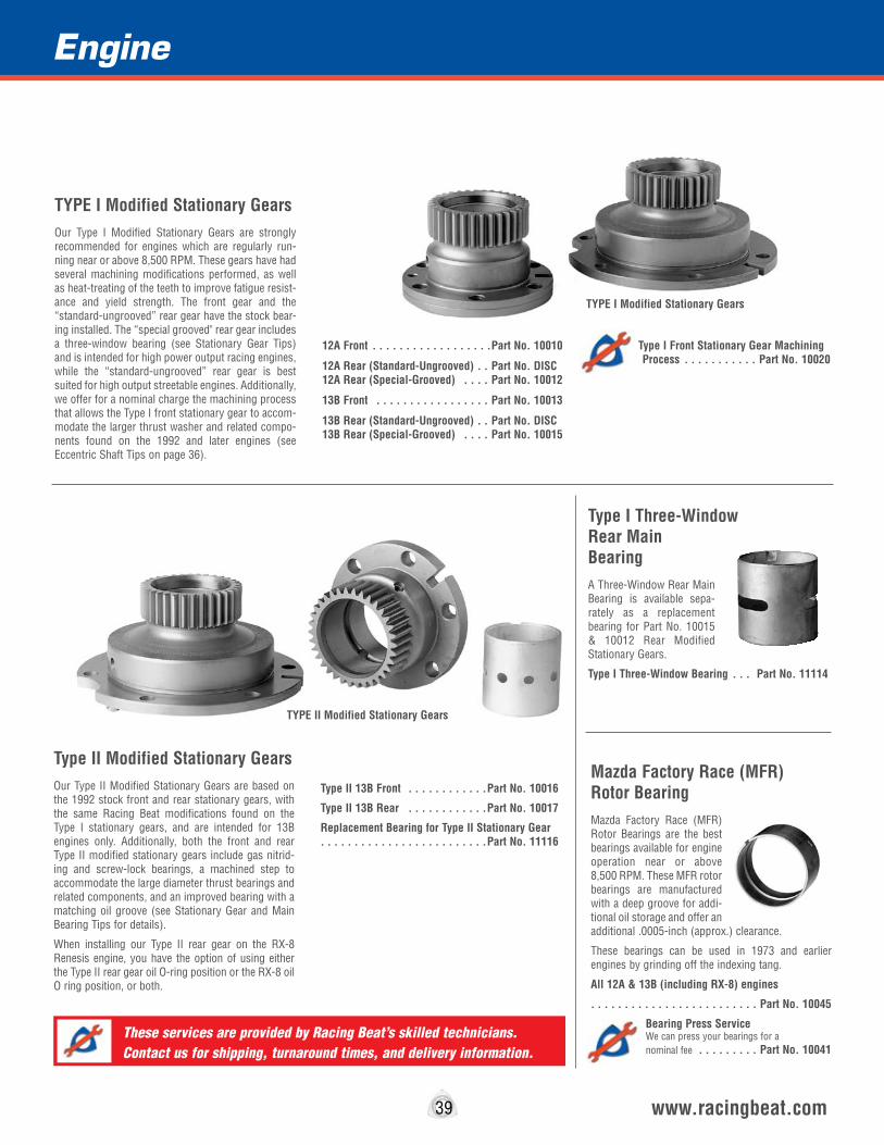
Mazda Factory Race (MFR) Rotor BearingMazda Factory Race (MFR) Rotor Bearings are the best bearings available for engine operation near or above 8,500 RPM. These MFR rotor bearings are manufactured with a deep groove for addi-tional oil storage and offer an additional .0005-inch (approx.) clearance.
These bearings can be used in 1973 and earlier engines by grinding off the indexing tang.
All 12A & 13B (including RX-8) engines
. . . . . . . . . . . . . . . . . . . . . . . . . Part No. 10045
Bearing Press Service We can press your bearings for a nominal fee . . . . . . . . . Part No. 10041
Engine
39 www.racingbeat.com
Type I Three-Window Rear Main BearingA Three-Window Rear Main Bearing is available sepa-rately as a replacement bearing for Part No. 10015 & 10012 Rear Modified Stationary Gears.
Type I Three-Window Bearing . . . Part No. 11114
Type II Modified Stationary GearsOur Type II Modified Stationary Gears are based on the 1992 stock front and rear stationary gears, with the same Racing Beat modifications found on the Type I stationary gears, and are intended for 13B engines only. Additionally, both the front and rear Type II modified stationary gears include gas nitrid-ing and screw-lock bearings, a machined step to accommodate the large diameter thrust bearings and related components, and an improved bearing with a matching oil groove (see Stationary Gear and Main Bearing Tips for details).
When installing our Type II rear gear on the RX-8 Renesis engine, you have the option of using either the Type II rear gear oil O-ring position or the RX-8 oil O ring position, or both.
Type II 13B Front . . . . . . . . . . . .Part No. 10016
Type II 13B Rear . . . . . . . . . . . .Part No. 10017
Replacement Bearing for Type II Stationary Gear . . . . . . . . . . . . . . . . . . . . . . . . .Part No. 11116
TYPE I Modified Stationary GearsOur Type I Modified Stationary Gears are strongly recommended for engines which are regularly run-ning near or above 8,500 RPM. These gears have had several machining modifications performed, as well as heat-treating of the teeth to improve fatigue resist-ance and yield strength. The front gear and the “standard-ungrooved” rear gear have the stock bear-ing installed. The “special grooved" rear gear includes a three-window bearing (see Stationary Gear Tips) and is intended for high power output racing engines, while the “standard-ungrooved” rear gear is best suited for high output streetable engines. Additionally, we offer for a nominal charge the machining process that allows the Type I front stationary gear to accom-modate the larger thrust washer and related compo-nents found on the 1992 and later engines (see Eccentric Shaft Tips on page 36).
12A Front . . . . . . . . . . . . . . . . . .Part No. 10010
12A Rear (Standard-Ungrooved) . . Part No. DISC 12A Rear (Special-Grooved) . . . . Part No. 10012
13B Front . . . . . . . . . . . . . . . . . Part No. 10013
13B Rear (Standard-Ungrooved) . . Part No. DISC 13B Rear (Special-Grooved) . . . . Part No. 10015
Type I Front Stationary Gear Machining Process . . . . . . . . . . . Part No. 10020
TYPE I Modified Stationary Gears
TYPE II Modified Stationary Gears
These services are provided by Racing Beat’s skilled technicians. Contact us for shipping, turnaround times, and delivery information.

40 www.racingbeat.com
Engine
Carbon Race Apex Seals*Our Race Apex Seals are specifically designed to replace the stock cast iron seals in engines operating near, or above, 8,500 RPM. These aluminum-filled carbon seals are a one-piece design, 2mm or 3mm in thickness, and must be used only with our special Race Apex Seal Springs. We do not believe these seals are appropriate for turbocharged applications because of their fragile nature if subject to detona-tion.
1974-85 12A (3mm)(ea) . . . . . . . .Part No. 11012
1974-85 13B (3mm)(ea) . . . . . . . .Part No. 11013
1986-92 Non-turbo (2mm)(ea) . . .Part No. 11011
Race Apex Seal Springs*Our Race Apex Seal Springs, specifically designed to fit the underside of our Race Apex Seals, provide proper pre-loading for these lighter one-piece seals. Unlike the stock inner and outer dual apex seal spring configuration on the 1986-92 engine applications, only one (1) Race Apex Seal Spring is required for each Race Apex Seal.
1974-85 12A (3mm)(ea) . . . . . . . .Part No. 11016
1974-85 13B (3mm)(ea) . . . . . . . .Part No. 11017
1986-92 Non-turbo (2mm)(ea) . . .Part No. 11015
Competition Engine MountsWe offer the Mazda Factory Race competition engine mounts for used in racing applications. Designed as a direct replacement for the original units, these mounts are 40% stiffer than the stock units. Two (2) required per vehicle.
1979-85 RX-7 (ea) . . . . . . . . . . . .Part No. 14036
1986-92 RX-7 (ea) . . . . . . . . . . . .Part No. 14038
Carbon Race Apex Seals & Springs
Front Engine MountRacing Beat's extremely popular Front Engine Mount allows any 1974-85 13B engine to be installed into any 1979-85 12A RX-7 chassis. (The stock Mazda front engine mount from a 1984-85 13B GSL-SE engine cannot be used as an alternative due to differences in the design of the GSL-SE chassis front cross member.) When the Racing Beat engine mount is used in con-junction with the 1984-85 GSL-SE 13B engine using any 1974-85 13B Engine RX-7 oil pan, this laser-cut stainless steel mount greatly simplifies installation.
RX-7 (12A to 13B Transplant) . . . . Part No. 11832
RX-7 12A . . . . . . . . . . . . . . . . . . Part No. 11837
1979-92 RX-7 Engine Torque BraceThe Racing Beat designed Engine Torque Brace, avail-able for all 1979-92 RX-7s, substantially reduces or eliminates the shuddering experienced by many RX-7 owners when engaging the clutch in either first or reverse gear. This kit requires that a small hole be drilled into the side of the engine compartment to accommodate the brace support arm.
1979-85 RX-7 (Shown) . . . . . . . . .Part No. 14030
1986-92 RX-7 Non-turbo (except convertible) . . . . . . . . . . . . . . . . . . . . . . . . .Part No. 14031
1987-91 RX-7 TURBO II . . . . . . . .Part No. 14032
13B Engine Conversion Mount
Engine Torque Brace
A great upgrade for RX-7’s equipped with high performance clutch
packages!

Race RotorsWe offer retained gear Race Rotors for high RPM operation, typically 8,500 RPM and above. The Racing Beat machining process, performed on otherwise stock rotors, involves the installation of a snap ring between the rotor gear and the basic rotor to prevent the rotor gear from working away from the basic rotor at higher RPM.
Because the 1989-92 style normally aspirated rotors are lighter than their 1986-88 counterparts and will fit correctly in all 1986-92 rotor housings, we retain the
gears on these later rotors and recommend them for all 1986-92 race engine building. When using these later style rotors in the 1986-88 engines you must use the 1989-92 front and rear counterweights or you will need to re-balance the assem-bly using your 1986-88 front and rear counterweights.
The 1989-91 Turbo II retained gear Race Rotors we offer are lighter than the 1986-88 stock Turbo II rotors and are intended only for use in 1989-91 Turbo II engines. The compression ratio differs between 1987-
88 (8.5:1) and 1989-91 (9.0:1) Turbo II engines, therefore these two series of rotors are not exactly interchangeable. Also, the 1987-88 ECU was not intended for use with the higher compression ratio. If you elect to use our 1989-91 Turbo II retained gear Race Rotors in your 1987-88 Turbo II engine, you will need to use the 1989-91 Turbo II front and rear coun-terweights or you will need to re-balance the assembly using your 1987-88 front and rear counterweights.
1989-92 Non-Turbo (each) . . . . . .Part No. DISC
1989-91 Turbo II (each) . . . . . . . .Part No. DISC
2004-06 RX-8 (each) . . . . . .Part No. DISC
Part numbers listed are for one (1) each.
Super Light-Weight Rotor AssembliesRacing Beat’s Super Light-Weight Rotor Assemblies are precision-machined lightened using a CNC (Computer Numerically Controlled) mill. In addition to the machine lightening process we also snap-ring the rotor gear to ensure it remains in place during high RPM operation. After completion of these machining processes our technicians fully balance these assemblies to provide an assembly capable of high RPM operation.
The 1974-85 12A rotor sets are based upon the 1983-85 asymmetrical, 9.6 lb.. rotors, lightened to approximately 8.5 lbs each, or 1.1 lb.. lighter.
The 13B Non-Turbo rotors are based on the stock 1989-92 rotors, with a 9.7:1 compression ratio, while the Turbo rotors are based on the stock 1989-91 rotors, with a 9.0:1 compression ratio. Both the 13B Non-Turbo & Turbo rotors initially weigh 9.7 lbs , and upon completion of the machining processes the weight of each is reduced to approximately 8.7 pounds.
12A Rotor Assembly* . . . . . . . . . Part No. DISC Replacement Rotor (Front) . . . . . . Part No. DISC Replacement Rotor (Rear) . . . . . . Part No. DISC
1986-92 Non-Turbo Assembly*. . . Part No. 10007 Replacement Rotor (each) . . . . . . Part No. 10036
1987-95 Turbo Assembly* . . . . . . Part No. 10004 Replacement Rotor (each) . . . . . . Part No. 10038
Lightened RX-8 Rotor AssemblyOur RX-8 Lightened Rotor Assemblies are precision-machined lightened using a CNC (Computer Numerically Controlled) mill. In addition to the machine lightening process we also snap-ring the rotor gear to ensure it remains in place during high RPM operation. After completion of these machining processes our technicians fully balance these assem-blies to provide an assembly capable of high RPM operation. These rotors are based on the stock 2004/5 RX-8 rotors. The initial weight of each rotor is approximately 9.2 pounds and upon completion of the machining processes the weight is reduced to approximately 9.0 pounds. This assembly includes the rotors, and a front and rear counterweight.
2004-011 RX-8 Assembly* . . Part No. 10008 Front Replacement Rotor (each) . . Part No. 10042 Rear Replacement Rotor (each) . . Part No. 10043
Lightened & Super Light-Weight Rotor Assemblies
Rotor Assemblies Include: Both Front & Rear Rotors and Counterweights
RX-8PRODUCT
Snap Ring
41 www.racingbeat.com
Engine
*Important Notes: 1. Previously, we recommended using the “1st generation” eccentric shaft - Mazda Part Number 3648-11-400 - with these 1986-95 Rotor Assemblies. It does not have the ther-mal bypass pellet (See Eccentric Shaft Tips) and is less costly than the stock 1986-95 eccentric shaft. However,
with the introduction of the lighter RX-8 eccentric shaft, Racing Beat has begun to change its Super Light-Weight rotor assemblies for use with this shaft.
2. The rotors in these assemblies have not been race clearanced. This procedure can be undertaken by Racing Beat for a nominal charge (PN 10040). Theses rotors do not have the MFR over-sized bearings installed--these bearings and the labor service are listed on Page 39.
RX-8PRODUCT
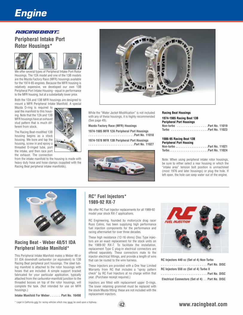
Peripheral Intake Port Rotor Housings*
We offer several types of Peripheral Intake Port Rotor Housings. The 12A model and one of the 13B models are the Mazda Factory Race (MFR) housings available for the 1974-85 engines. Because the MFR housing is relatively expensive, we developed our own 13B Peripheral Port Intake Housing - equal in performance to the MFR housing, but at a substantially lower price.
Both the 12A and 13B MFR housings are designed to mount a MFR Peripheral Intake Manifold. A special Mazda O-ring is required to seal the manifold to this hous-ing. Note that the 12A and 13B MFR housings have an exhaust stud pattern that is much dif-ferent from stock.
The Racing Beat-modified 13B housing begins as a stock housing. We bore and tap the housing, screw in and epoxy a threaded O-ringed tube, port the intake, and then race port the exhaust. The connection from the intake manifold to the housing is made with heavy duty hose and hose clamps (supplied with the Racing Beat peripheral intake manifolds).
While the “Water Jacket Modification” is not included with any of these housings, it is highly recommended (See page 49).
Mazda Factory Race (MFR) Housings
1974-1985 MFR 12A Peripheral Port Housings . . . . . . . . . . . . . . . . . . . . . . . . .Part No. 11018
1974-1978 MFR 13B Peripheral Port Housings . . . . . . . . . . . . . . . . . . . . . . . . .Part No. 11027
Racing Beat Housings
1974-1985 Racing Beat 13B Peripheral Port Housings Non-turbo . . . . . . . . . . . . . . . . .Part No. 11019 Turbo . . . . . . . . . . . . . . . . . . . .Part No. 11023
1986-95 Racing Beat 13B Peripheral Port Housing Non-turbo . . . . . . . . . . . . . . . . . .Part No. 11021 Turbo . . . . . . . . . . . . . . . . . . . . .Part No. 11024
Note: When using peripheral intake rotor housings, be sure to either select a rear housing in which the “intake area” tension bolt position is unmachined (most 1976 and later housings) or plug the hole. If left open, the hole can seep water out of the engine.
SectionEngine - InternalEngine
42 www.racingbeat.com* Legal in California only for racing vehicles which may never be used upon a highway.
Racing Beat - Weber 48/51 IDA Peripheral Intake Manifold*This Peripheral Intake Manifold mates a Weber 48 or 51 IDA downdraft carburetor (or equivalent) to 13B Racing Beat peripheral port housings. The steel tub-ing manifold is attached to the rotor housings with hoses that are included. A simple support bracket fabricated for your particular application, typically attached from the carburetor-manifold junction to the threaded bosses on top of the rotor housings, will complete the task. (Not intended for use on MFR housings.)
Intake Manifold For Weber . . . . . . Part No. 16490
RC® Fuel Injectors* 1989-92 RX-7We offer RC Fuel Injector replacements for all 1989-92 model year stock RX-7 applications.
RC Engineering, founded by motorcycle drag racer Russ Colins, has been supplying high performance fuel injection components for the performance and racing aftermarket for over three decades.
These high resistance (12-16 ohms) Disc Type injec-tors are an exact replacement for the stock units on the 1989-92 RX-7. To facilitate the installation, replacement Type C plug-in electrical connectors are offered separately. These connectors mate to the injector electrical fittings, and provide a length of wire that can be routed to the wire harness.
These Injectors are provided with a One Year Limited Warranty from RC that includes a “spray pattern check” by RC Fuel Injectors at no charge within that year. (Purchase receipt required.)
Injectors are fitted with replacement upper O-rings. The lower retaining grommet must be replaced with the stock Mazda fitting: these are not included with the replacement injectors.
RC Injectors 440 cc (Set of 4) Non-Turbo. . . . . . . . . . . . . . . . . . . . . . . . . Part No. DISCRC Injectors 550 cc (Set of 4) Turbo II. . . . . . . . . . . . . . . . . . . . . . . . . Part No. DISC
Electrical Connectors (Set of 4) . . Part No. DISC
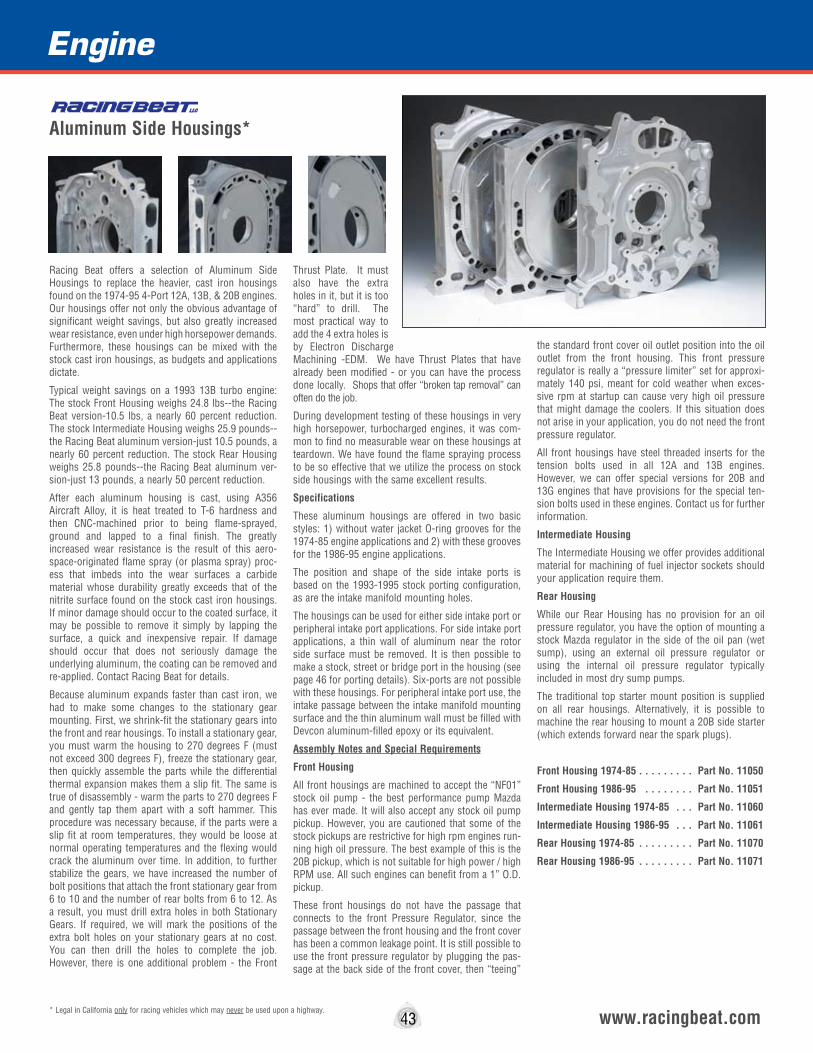
Section
43 www.racingbeat.com* Legal in California only for racing vehicles which may never be used upon a highway.
Racing Beat offers a selection of Aluminum Side Housings to replace the heavier, cast iron housings found on the 1974-95 4-Port 12A, 13B, & 20B engines. Our housings offer not only the obvious advantage of significant weight savings, but also greatly increased wear resistance, even under high horsepower demands. Furthermore, these housings can be mixed with the stock cast iron housings, as budgets and applications dictate.
Typical weight savings on a 1993 13B turbo engine: The stock Front Housing weighs 24.8 lbs--the Racing Beat version-10.5 lbs, a nearly 60 percent reduction. The stock Intermediate Housing weighs 25.9 pounds--the Racing Beat aluminum version-just 10.5 pounds, a nearly 60 percent reduction. The stock Rear Housing weighs 25.8 pounds--the Racing Beat aluminum ver-sion-just 13 pounds, a nearly 50 percent reduction.
After each aluminum housing is cast, using A356 Aircraft Alloy, it is heat treated to T-6 hardness and then CNC-machined prior to being flame-sprayed, ground and lapped to a final finish. The greatly increased wear resistance is the result of this aero-space-originated flame spray (or plasma spray) proc-ess that imbeds into the wear surfaces a carbide material whose durability greatly exceeds that of the nitrite surface found on the stock cast iron housings. If minor damage should occur to the coated surface, it may be possible to remove it simply by lapping the surface, a quick and inexpensive repair. If damage should occur that does not seriously damage the underlying aluminum, the coating can be removed and re-applied. Contact Racing Beat for details.
Because aluminum expands faster than cast iron, we had to make some changes to the stationary gear mounting. First, we shrink-fit the stationary gears into the front and rear housings. To install a stationary gear, you must warm the housing to 270 degrees F (must not exceed 300 degrees F), freeze the stationary gear, then quickly assemble the parts while the differential thermal expansion makes them a slip fit. The same is true of disassembly - warm the parts to 270 degrees F and gently tap them apart with a soft hammer. This procedure was necessary because, if the parts were a slip fit at room temperatures, they would be loose at normal operating temperatures and the flexing would crack the aluminum over time. In addition, to further stabilize the gears, we have increased the number of bolt positions that attach the front stationary gear from 6 to 10 and the number of rear bolts from 6 to 12. As a result, you must drill extra holes in both Stationary Gears. If required, we will mark the positions of the extra bolt holes on your stationary gears at no cost. You can then drill the holes to complete the job. However, there is one additional problem - the Front
Thrust Plate. It must also have the extra holes in it, but it is too “hard” to drill. The most practical way to add the 4 extra holes is by Electron Discharge Machining -EDM. We have Thrust Plates that have already been modified - or you can have the process done locally. Shops that offer “broken tap removal” can often do the job.
During development testing of these housings in very high horsepower, turbocharged engines, it was com-mon to find no measurable wear on these housings at teardown. We have found the flame spraying process to be so effective that we utilize the process on stock side housings with the same excellent results.
Specifications
These aluminum housings are offered in two basic styles: 1) without water jacket O-ring grooves for the 1974-85 engine applications and 2) with these grooves for the 1986-95 engine applications.
The position and shape of the side intake ports is based on the 1993-1995 stock porting configuration, as are the intake manifold mounting holes.
The housings can be used for either side intake port or peripheral intake port applications. For side intake port applications, a thin wall of aluminum near the rotor side surface must be removed. It is then possible to make a stock, street or bridge port in the housing (see page 46 for porting details). Six-ports are not possible with these housings. For peripheral intake port use, the intake passage between the intake manifold mounting surface and the thin aluminum wall must be filled with Devcon aluminum-filled epoxy or its equivalent.
Assembly Notes and Special Requirements
Front Housing
All front housings are machined to accept the “NF01” stock oil pump - the best performance pump Mazda has ever made. It will also accept any stock oil pump pickup. However, you are cautioned that some of the stock pickups are restrictive for high rpm engines run-ning high oil pressure. The best example of this is the 20B pickup, which is not suitable for high power / high RPM use. All such engines can benefit from a 1” O.D. pickup.
These front housings do not have the passage that connects to the front Pressure Regulator, since the passage between the front housing and the front cover has been a common leakage point. It is still possible to use the front pressure regulator by plugging the pas-sage at the back side of the front cover, then “teeing”
the standard front cover oil outlet position into the oil outlet from the front housing. This front pressure regulator is really a “pressure limiter” set for approxi-mately 140 psi, meant for cold weather when exces-sive rpm at startup can cause very high oil pressure that might damage the coolers. If this situation does not arise in your application, you do not need the front pressure regulator.
All front housings have steel threaded inserts for the tension bolts used in all 12A and 13B engines. However, we can offer special versions for 20B and 13G engines that have provisions for the special ten-sion bolts used in these engines. Contact us for further information.
Intermediate Housing
The Intermediate Housing we offer provides additional material for machining of fuel injector sockets should your application require them.
Rear Housing
While our Rear Housing has no provision for an oil pressure regulator, you have the option of mounting a stock Mazda regulator in the side of the oil pan (wet sump), using an external oil pressure regulator or using the internal oil pressure regulator typically included in most dry sump pumps.
The traditional top starter mount position is supplied on all rear housings. Alternatively, it is possible to machine the rear housing to mount a 20B side starter (which extends forward near the spark plugs).
Front Housing 1974-85 . . . . . . . . . Part No. 11050
Front Housing 1986-95 . . . . . . . . Part No. 11051
Intermediate Housing 1974-85 . . . Part No. 11060
Intermediate Housing 1986-95 . . . Part No. 11061
Rear Housing 1974-85 . . . . . . . . . Part No. 11070
Rear Housing 1986-95 . . . . . . . . . Part No. 11071
Engine
Aluminum Side Housings*
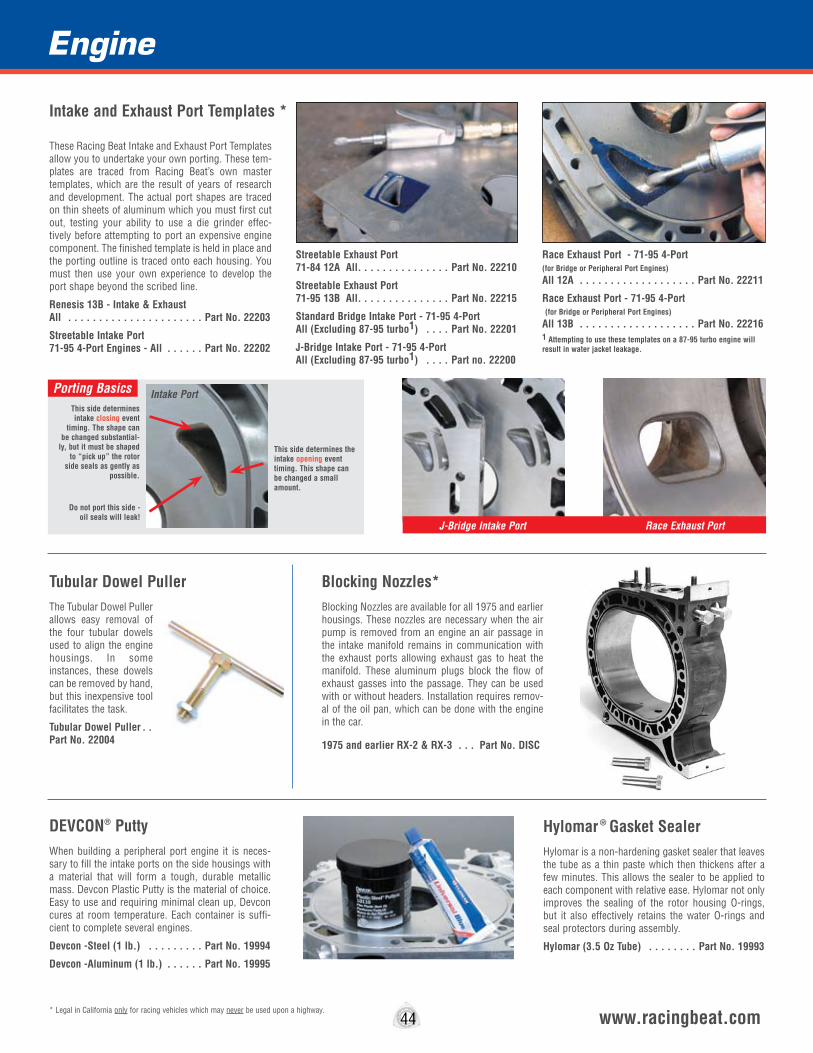
Hylomar ® Gasket SealerHylomar is a non-hardening gasket sealer that leaves the tube as a thin paste which then thickens after a few minutes. This allows the sealer to be applied to each component with relative ease. Hylomar not only improves the sealing of the rotor housing O-rings, but it also effectively retains the water O-rings and seal protectors during assembly.
Hylomar (3.5 Oz Tube) . . . . . . . . Part No. 19993
DEVCON® PuttyWhen building a peripheral port engine it is neces-sary to fill the intake ports on the side housings with a material that will form a tough, durable metallic mass. Devcon Plastic Putty is the material of choice. Easy to use and requiring minimal clean up, Devcon cures at room temperature. Each container is suffi-cient to complete several engines.
Devcon -Steel (1 lb.) . . . . . . . . . Part No. 19994
Devcon -Aluminum (1 lb.) . . . . . . Part No. 19995
Engine
44 www.racingbeat.com* Legal in California only for racing vehicles which may never be used upon a highway.
Tubular Dowel PullerThe Tubular Dowel Puller allows easy removal of the four tubular dowels used to align the engine housings. In some instances, these dowels can be removed by hand, but this inexpensive tool facilitates the task.
Tubular Dowel Puller . .Part No. 22004
Intake and Exhaust Port Templates *
Blocking Nozzles*Blocking Nozzles are available for all 1975 and earlier housings. These nozzles are necessary when the air pump is removed from an engine an air passage in the intake manifold remains in communication with the exhaust ports allowing exhaust gas to heat the manifold. These aluminum plugs block the flow of exhaust gasses into the passage. They can be used with or without headers. Installation requires remov-al of the oil pan, which can be done with the engine in the car.
1975 and earlier RX-2 & RX-3 . . . Part No. DISC
These Racing Beat Intake and Exhaust Port Templates allow you to undertake your own porting. These tem-plates are traced from Racing Beat’s own master templates, which are the result of years of research and development. The actual port shapes are traced on thin sheets of aluminum which you must first cut out, testing your ability to use a die grinder effec-tively before attempting to port an expensive engine component. The finished template is held in place and the porting outline is traced onto each housing. You must then use your own experience to develop the port shape beyond the scribed line.
Renesis 13B - Intake & Exhaust All . . . . . . . . . . . . . . . . . . . . . . Part No. 22203
Streetable Intake Port 71-95 4-Port Engines - All . . . . . . Part No. 22202
Streetable Exhaust Port 71-84 12A All . . . . . . . . . . . . . . . Part No. 22210
Streetable Exhaust Port 71-95 13B All . . . . . . . . . . . . . . . Part No. 22215
Standard Bridge Intake Port - 71-95 4-Port All (Excluding 87-95 turbo1) . . . . Part No. 22201
J-Bridge Intake Port - 71-95 4-Port All (Excluding 87-95 turbo1) . . . . Part no. 22200
Race Exhaust Port - 71-95 4-Port (for Bridge or Peripheral Port Engines) All 12A . . . . . . . . . . . . . . . . . . . Part No. 22211
Race Exhaust Port - 71-95 4-Port (for Bridge or Peripheral Port Engines) All 13B . . . . . . . . . . . . . . . . . . . Part No. 222161 Attempting to use these templates on a 87-95 turbo engine will result in water jacket leakage.
J-Bridge Intake Port Race Exhaust Port
This side determines intake closing event
timing. The shape can be changed substantial-
ly, but it must be shaped to “pick up” the rotor
side seals as gently as possible.
Do not port this side - oil seals will leak!
This side determines the intake opening event timing. This shape can be changed a small amount.
Porting Basics Intake Port
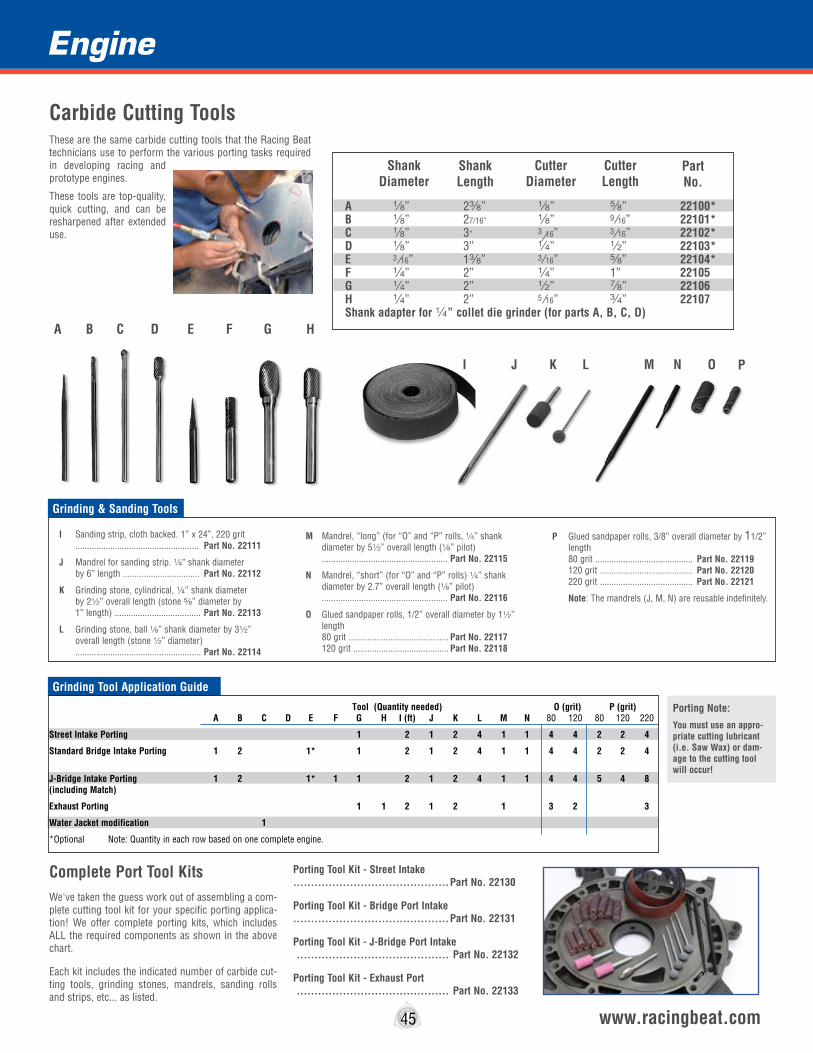
Engine
A 8” 2a” 8” s” 22100*B 8” 27/16” 8” 9 16” 22101*C 8” 3” 3 16” 3 16” 22102*D 8” 3” 4” 2” 22103*E 3 16” 1a” 3 16” s” 22104*F 4” 2” 4” 1” 22105G 4” 2” 2” d” 22106H 4” 2” 5 16” w” 22107Shank adapter for 4” collet die grinder (for parts A, B, C, D)
45 www.racingbeat.com
Carbide Cutting ToolsThese are the same carbide cutting tools that the Racing Beat technicians use to perform the various porting tasks required in developing racing and prototype engines.
These tools are top-quality, quick cutting, and can be resharpened after extended use.
I Sanding strip, cloth backed. 1” x 24”, 220 grit ..................................................... Part No. 22111
J Mandrel for sanding strip. 4” shank diameter by 6” length ................................. Part No. 22112
K Grinding stone, cylindrical, 4” shank diameter by 22” overall length (stone s” diameter by 1” length) ..................................... Part No. 22113
L Grinding stone, ball 8” shank diameter by 32” overall length (stone 2” diameter) ...................................................... Part No. 22114
M Mandrel, “long” (for “O” and “P” rolls, 4” shank diameter by 52” overall length (8” pilot) ...................................................... Part No. 22115
N Mandrel, “short” (for “O” and “P” rolls) 4” shank diameter by 2.7” overall length (8” pilot) ...................................................... Part No. 22116
O Glued sandpaper rolls, 1/2” overall diameter by 12” length 80 grit ........................................... Part No. 22117 120 grit ......................................... Part No. 22118
P Glued sandpaper rolls, 3/8” overall diameter by 11/2” length 80 grit .......................................... Part No. 22119 120 grit ........................................ Part No. 22120 220 grit ........................................ Part No. 22121
Note: The mandrels (J, M, N) are reusable indefinitely.
ShankDiameter
CutterDiameter
CutterLength
PartNo.
ShankLength
Grinding & Sanding Tools
A B C D E F G H
I J K L M N O P
T ool (Quantity needed) O (grit) P (grit) A B C D E F G H I (ft) J K L M N 80 120 80 120 220
Street Intake Porting 1 2 1 2 4 1 1 4 4 2 2 4
Standard Bridge Intake Porting 1 2 1* 1 2 1 2 4 1 1 4 4 2 2 4
J-Bridge Intake Porting 1 2 1* 1 1 2 1 2 4 1 1 4 4 5 4 8 (including Match)
Exhaust Porting 1 1 2 1 2 1 3 2 3
Water Jacket modification 1
*Optional Note: Quantity in each row based on one complete engine.
Grinding Tool Application Guide
Porting Note:You must use an appro-priate cutting lubricant (i.e. Saw Wax) or dam-age to the cutting tool will occur!
Complete Port Tool KitsWe've taken the guess work out of assembling a com-plete cutting tool kit for your specific porting applica-tion! We offer complete porting kits, which includes ALL the required components as shown in the above chart.
Each kit includes the indicated number of carbide cut-ting tools, grinding stones, mandrels, sanding rolls and strips, etc... as listed.
Porting Tool Kit - Street Intake ............................................Part No. 22130
Porting Tool Kit - Bridge Port Intake ............................................Part No. 22131
Porting Tool Kit - J-Bridge Port Intake ........................................... Part No. 22132
Porting Tool Kit - Exhaust Port ........................................... Part No. 22133
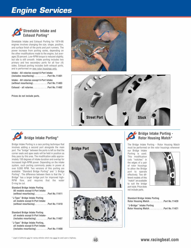
Engine Services
46 www.racingbeat.com
Streetable Intake and Exhaust Porting for 1974-95 engines involves changing the size, shape, position, and surface finish of the ports and port runners. The power increase from porting varies, depending on the other modifications made to the engine, but aver-ages 20 percent. Low-RPM torque is reduced slightly, but idle is still smooth. Intake porting includes two primary and two secondary ports for all four (4) sides. Exhaust porting includes both exhaust ports, and is performed on new rotor housings only.
Intake - All rotaries except 6-Port Intake (includes resurfacing) . . . . . . . . .Part No.11401
Intake - All rotaries except 6-Port Intake (without resurfacing) . . . . . . . . . .Part No.11403
Exhaust - all rotaries . . . . . . . . . .Part No.11402
Prices do not include parts.
The Bridge Intake Porting - Rotor Housing Match must be performed on the rotor housings whenever our Bridge Intake Porting is used. This modification cuts “notches” in the edges of a pair of rotor housings to allow the Bridge port to operate effectively. Two dif-ferent models of this “match” are available to suit the bridge port style. Price does not include parts.
Standard Bridge Intake Porting Rotor Housing Match . . . . . . . . . .Part No.11420
“J-Bridge” Intake Porting Rotor Housing Match . . . . . . . . . .Part No.11421
Bridge Intake Porting is a race porting technique that involves adding a second port alongside the main port. The “bridge” between the ports is left so that the corner seals and apex seals will be held in position as they pass by this area. The modification adds approx-imately 150 degrees of intake duration and overlap for increased high-RPM power. Depending on the intake system, such porting commonly peaks in power at over 9,000 RPM. Two versions of this porting are available: “Standard Bridge Porting” and “J Bridge Porting”. The difference between them is that the “J Bridge” has a larger bridge port for improved high-RPM flow, and requires that the water O-ring be cut.
Standard Bridge Intake Porting All models except 6-Port Intake (without resurfacing) . . . . . . . . .Part No.11411
“J-Type” Bridge Intake Porting all models except 6-Port Intake (without resurfacing) . . . . . . . . .Part No.11410
Standard Bridge Intake Porting all models except 6-Port Intake- (includes resurfacing) . . . . . . . .Part No.11407
“J-Type” Bridge Intake Porting, all models except 6-Port Intake (includes resurfacing) . . . . . . . .Part No.11408
* Legal in California only for racing vehicles which may never be used upon a highway.
Street Port
Bridge Port
Stock
Streetable Intake and Exhaust Porting*
Bridge Intake Porting - Rotor Housing Match*Bridge Intake Porting*
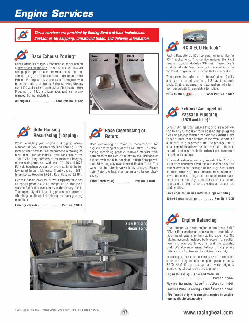
Engine Services
Side Housing Resurfacing (Lapping)When rebuilding your engine it is highly recom-mended that you resurface the side housings if the level of wear permits. We recommend removing no more than .002” of material from each side of the 1986-95 housing surfaces to maintain the integrity of the O-ring grooves. With the 1971-85 and RX-8 Renesis housings we can remove material to the fol-lowing minimum thicknesses: Front Housing 1.568”; Intermediate Housing 1.955”; Rear Housing 2.355”.
Our resurfacing process utilizes a lapping table and an optical grade polishing compound to produce a surface finish that exceeds even the factory finish. The superiority of this lapping process well exceeds what is generally available through surface grinding operations.
Labor (each side) . . . . . . . . . . . .Part No. 11041
Engine BalancingIf you intend your race engine to run above 8,500 RPM or if the engine is a non-standard assembly, we recommend balancing the rotating assembly. The rotating assembly includes both rotors, main pulley, front and rear counterweights. and the eccentric shaft. We also recommend balancing the pressure plate and the flywheel on the rotating assembly.
In our experience it is not necessary to re-balance a stock or mildly modified engine operating below 8,500 RPM if the rotating parts were originally intended by Mazda to be used together.
Engine Balancing - Labor and Materials . . . . . . . . . . . . . . . . . . . . . . . . .Part No. 11042
Flywheel Balancing - Labor1 . . . .Part No. 11044
Pressure Plate Balancing - Labor1 Part No. 11043
(1Performed only with complete engine balancing - not available separately).
47 www.racingbeat.com
Race Exhaust Porting*Race Exhaust Porting is a modification performed on a new rotor housing only. This modification involves changing the profile at the internal end of the port, and blending that profile into the port outlet. Race Exhaust Porting is only appropriate for engines with bridge or peripheral porting. Either Blocking Nozzles (for 1975 and earlier housings) or Air Injection Hole Plugging (for 1976 and later housings) are recom-mended, but not included.
All engines . . . . . . . . . . . .Labor Part No. 11412
Exhaust Air Injection Passage Plugging (1976 and later)*
Exhaust Air Injection Passage Plugging is a modifica-tion to a 1976 and later rotor housing that plugs the fresh air passage which runs from the exhaust outlet flange surface to the bottom of the exhaust port. An aluminum plug is pressed into the passage, and a small disc of metal is welded into the hole at the bot-tom of the steel sleeve in the exhaust port to smooth the exhaust gas flow.
This modification is not very important for 1976 to 1980 rotor housings if you use our header since this header covers the passage at the engine-to-header interface. However, if this modification is not done to 1981 and later housings, and if a stock intake mani-fold is used on the engine, the hot exhaust can back-flow up the intake manifold, creating an undesirable heating effect.
Price does not include rotor housings or porting.
1976-95 rotor housings . . . . . . . . Part No.11305
Race Clearancing of Rotors Race clearancing of rotors is recommended for engines operating at or above 8,500 RPM. The clear-ancing machining process removes material from both sides of the rotor to minimize the likelihood of contact with the side housings in high horsepower, high RPM engines (see Internal Engine Tips). The weight of the rotor is only slightly changed. Please note: Rotor bearings must be installed before clear-ancing.
Labor (each rotor) . . . . . . . . . . .Part No. 10040
* Legal in California only for racing vehicles which may never be used upon a highway.
RX-8 ECU Reflash*Racing Beat offers a ECU reprogramming service for RX-8 applications. This service updates the RX-8 Program Control Module (PCM) with Racing Beat’s customized data. Visit the website, or contact us for the latest programming versions that are available.
This service is performed “in-house” at our facility and can be undertaken on a 1-2 day turnaround basis. Contact us directly, or download an order form from our website for complete information.
2004-06 RX-8 . . . . . . .Labor Part No. 11307
Race Exhaust Port
Stock Exhaust Port
These services are provided by Racing Beat’s skilled technicians. Contact us for shipping, turnaround times, and delivery information.
Side Housing Resurfacing
RX-8PRODUCT
Water Cooling System
The Mazda rotary engine rejects greater amounts of heat via the oil and water cooling systems than do reciprocating engines of similar horsepower output. This is due in large part to the relatively high surface-to-volume ratio typical in rotary engines, as com-pared to reciprocating engines - rotary engines have a greater surface area exposed to combustion gases. Because more heat is put into the water and oil cool-ing jackets, more heat must be rejected in the water and oil coolers. The water cooling system is respon-sible for rejecting roughly two-thirds of the engine heat, while the oil cooling system rejects the remain-ing roughly one-third of engine heat. To ensure maximum engine life it is essential that a large, well-designed radiator be used.
In the past, Mazda’s stock coolers were more than adequate for not only stock applications, but also for mildly modified street engines, assuming the cooling components are in good condition. However, starting in 1993 the capacity of the stock cooling system was designed by Mazda to barely meet the needs of the stock car with no excess capacity for very demanding situations or modifications that increase the heat load on the engine. Based on a number of tests, we believe the primary cause of this problem is aerodynamic. In both the 1993-95 RX-7 and the RX-8, the air path out of the radiator is convoluted and restricted - leading to high water and oil temperatures. We have tried larger radiators, and to date, they have not helped. We have seen some improvement from improved sealing and directing the air into the radiator (using a spoiler lip under the vehicle) to create a lower pres-sure area under the car, to remove hot air.
With any rotary engine application it is wise to moni-tor the water and oil temperature of the engine. This is particularly difficult in the RX-8 because Mazda chose to have a water temperature gauge that does not give a linear, proportional reading. What this means is that, as the actual water temperature rises to about 170° the gauge stops moving, when the engine coolant temperature reaches 205° it starts moving again! This gives you a false impression of the engine cooling in cases where knowledge of increasing engine temperature might cause you to drive to lessen the heat load on the system. We disa-gree with this approach to informing the driver! For this reason, we developed a module for the RX-8 which features a set of calibrated water, oil pressure and oil temperature gauges. (See page 53)
Water Cooling Tips
1. Change radiator hoses, heater hoses, and fan belts every eighteen months. At the same time, flush the cooling system and replace with a 50/50 mixture of name brand antifreeze and, preferably, distilled water (to minimize mineral contamination).
2. The lower radiator hose must have a steel wire “spring form” inside it to prevent it from collapsing at high RPM from the low pressure (suction) at the inlet of the water pump. Squeeze the lower hose to deter-mine if a spring form has been installed. If not, replace the hose with one that contains this critical feature. The top hose does not require a spring form.
3. Do not remove the stock fan shroud or front under-tray - they aid cooling in street applications.
4. Fan clutches do fail on occasion. Check the fan clutch with the engine warm. If the fan turns freely by hand have your Mazda dealer inspect the unit, or refer to your factory service manual for inspection instruc-tions.
5. Avoid using any “stop leak” product, except in an emergency. If you are forced to use such a product, replace or recore the radiator as soon as possible.
6. Mazda uses a “bypass” type water thermostat. If you intend to use the water pump in a racing application this thermostat must be removed and the hole below it plugged. A 2” NPT pipe thread tap and matching plug will accomplish this task.
The thermostat should be removed and the bypass plugged for racing applications, but NEVER for street use. Do not use “flow restrictors” in the cooling sys-tem, free flow is best.
7. Engine overheating is often the result of water O-ring failure, the rotary engine’s equivalent of a reciprocating engine’s cylinder head gasket failure. Additional symptoms of water O-ring failure include: hard starting, especially when cold, since water will leak into the rotor housings and wet the plugs; white “smoke” (steam) in the exhaust; and loss of coolant. Testing the coolant for carbon monoxide contamina-tion is a fairly accurate indicator of water O-ring fail-ure. If any of the water O-rings have failed, the only remedy is a complete engine rebuild.
8. Inspect the condition of the caps on the cooling system to confirm they are sealing well. If they can-not adequately contain pressure, the coolant will likely boil - especially at higher altitudes.
9. The factory stock thermostat opens at approxi-
mately 180°F (82°C). Under normal driving condi-tions the water temperature should not exceed 185°F. Should the temperature reach 200°F fairly slowly, engine damage is not likely. If the rise is fairly rapid- due to a broken hose or fan belt, for example, engine damage is more likely.
We strongly recommend that high quality gauges be used for reading engine coolant temperatures, with the mechanical versions typically being more reliable and easier to calibrate. To calibrate a gauge, simply boil a pan of distilled water and place the temperature sender in the water. Do not allow the sender to come in contact with the sides or bottom of the pan. The gauge should read at, or very near 212° F (100°C). If it does not, follow the manufacturer’s instructions for re-calibration.
In most 1995 and earlier rotaries, the water tempera-ture gauge should be installed in the back of the water pump, just below the thermostat. The original metric-thread hole can be tapped for either 4” or a” pipe thread to simplify the installation of “American” gaug-es. In the RX-8 this position is not practical, so we developed a special adapter fitting that can be mounted in the heater hose (See page 53).
10. If you intend your engine to be used for road rac-ing, your best choices for a radiator are either the Mazda Factory Race aluminum radiator or equivalent, paying attention to plumbing requirements.
11. Water cavitation is a serious problem with engines running at higher RPMs. Water pump cavi-tation occurs when water is no longer able to flow smoothly, but rather develops tiny water vapor bub-bles around the water pump impeller. When this cavitation occurs, water flow rates decrease and cooling is impaired. The onset of cavitation is gradu-al at first and worsens as both engine RPM and temperature increase.
Note: We do not recommend either the Single or Double-Sheave Main Drive Pulley be installed on engines that are typically used for “stop and go” street driving: however, if your engine is commonly run up to 8,000 RPM, our Double Sheave Main Drive Pulley will prove beneficial (see page 50).
In general, do not use our Double Sheave Main Drive Pulley on 1987-91 Turbo II engines unless modifica-tions have been made - shorter intake runners. etc. - to increase the engine’s RPM range substantially. Turbo II engines produce their peak power in a lower RPM range, relative to their non-turbo counterparts.
48 www.racingbeat.com
Fuel Injected Aviation Engine - 192 HP

RX-8 Water Temperature AdapterThe Water Temperature Adapter allows you to incorporate a water temper-ature gauge in your RX-8. C N C -m a c h i n e d from billet a luminum, this adapter fitting allows e a s y installation of a standard a” sender unit utilized by most of the popular aftermar-ket gauges. The adapter includes installation instruc-tions and hose clamps.
2004-11 RX-8 . . . . . . . . . .Part No. 11493
49 www.racingbeat.com
Rotor Housing Water Jacket ModificationThe Rotor Housing Water Jacket Modification is intended to improve cooling in the “hot zone” of the rotor housing to increase both housing and seal life. This modification involves cutting grooves in the water jacket in the vicinity of the leading and trailing spark plugs to increase heat transfer out of the housing inner surface. The modification can be performed only on a new rotor housing, and is only appropriate for race and the most extreme street use. To perform your own modifications, refer to the carbide cutting tool chart on page 45.
Labor Charge (each) . . . . . . . . . . .Part No. 11488
Heater-Water-Outlet PlugA Heater-Water-Outlet Plug is an inexpensive and reliable way of plugging the heater water outlet port on the rear housing for those who do not use a heater.
1981 and earlier rotaries . . . . . . . . . . . . . . . . . . . . . . . . .Part No. 11490
KOYO® RadiatorsKOYO Radiators are intended for high performance street or racing applications when engine cooling requirements are at the maximum. The all-aluminum tubes, fins, headers and brackets are brazed together using state-of-the-art technology to bond these com-ponents into a virtually indestructible radiator.
Hand-crafted heliarc soldering, mirror finished surfac-es, and OEM specification mounting points are the hallmarks of the superior KOYO quality and reputa-tion.
All RX-7 R-Core Series radiators units incorporate 2 1/16” thick cores for improved cooling efficiency. The V-Core RX-8 radiator features the standard 1 7/16” thick core.
Also available for the 1989-92 and 1993-95 RX-7 are the N-Flo (Return Flow Technology) radiators that offer additional cooling efficiency as compared to the standard radiators. (Special fitment required.)
KOYO all-aluminum racing radiators are produced for manual transmission applications only. Automatic transmission equipped car will require an external
transmission oil cooler for correct operation.
During testing for the RX-8 application, we found that the use of a larger radiator did not offer signifi-cant cooling improvements for “stop-and-go” street applications. The likely benefits of a larger radiator for this application will be noticed under racing or higher speed conditions.
1986-88 RX-7 (MT only) . . . . . . . . Part No. 11494
1989-92 RX-7 (MT only) . . . . . . . . Part No. 11495
1989-92 RX-7 (N-Flo Double Pass) . . Part No. 11496
1993-95 RX-7 (MT only) . . . . . . . . Part No. 11497
1993-95 RX-7 (N-Flo Double Pass) . . Part No. 11498
2004-11 RX-8 (MT only) . . . . Part No. 11499
RX-8PRODUCT
RX-8PRODUCT
Water Cooling
Custom Modification For Race Application

Water Cooling
50 www.racingbeat.com
Aluminum Double Sheave Main Drive PulleyThe Aluminum Double Sheave Main Drive Pulley is designed for high performance/RPM street and mod-erate racing use, slowing the water pump and alter-nator 13-15%, thereby reducing cavitation and power loss. If used with our Aluminum Double Sheave Alternator Pulley, you can have a true dual belt sys-tem. The stock air conditioning pulley is accommo-dated. Timing marks are provided at 10° ATC, 0°, 10° and 20° BTC.*
1974-92 All (Weight 16 oz) . . . . . . Part No. 11469
Aluminum Double Sheave Alternator PulleyThe Aluminum Double Sheave Alternator Pulley reduces alternator RPM approximately 20% from stock RPM, and is intended for high performance and moderate race use. It is compatible with either the stock main pulley, or assuming you are not using the air pump, our Aluminum Double Sheave Main Drive Pulley.*
1974-92 All (Weight 7.2 oz) . . . . Part No. 11479
Aluminum Single Sheave Main Drive PulleyThis pulley reduces the water pump/alternator drive ratio substantially (see chart below) to avoid water pump cavitation and alternator damage due to the extreme RPMs encountered in racing. It also reduces the engine's rotating inertia and the power loss to the accessories. The 1971-73 pulley has no provision for mounting the cooling fan. These pulleys are provided with a series of engraved timing marks.*
1974-92 All (Weight 6.4 oz) . . . . . Part No.11473
Aluminum Single Sheave Alternator PulleyThis Mazda Factory Race (MFR) Aluminum Single Sheave Alternator Pulley reduces alternator RPM approximately 20% from stock for street high-per-formance and racing use. It is intended for use with the Single Sheave Main Drive Pulley, although it can be used with the stock main drive pulley. The pulley is bored 15mm for use on small shaft alternators, although it can be bored larger if necessary.*
1971-92 All (Weight 3.2 oz) . . . . . Part No.11492
Single Sheave
Alternator Main Drive Alternator Main Drive
Double Sheave
*Note: It is not practical to offer a “standard” replacement belt due to the variations of the RX-7 chassis. After measuring the distance required for your application, we suggest you contact your local auto parts store to obtain an appropriate 3/8-inch wide replacement belt.
Maximum Engine RPM With Various Water Pump Pulley Combinations
Pulley Combination
1993-95 Stock
Water Pump
1974-85 Stock or Race Cast Iron Water
Pump
1986-88 Stock
Water Pump
1989-92 Stock
Water Pump
Stock main drive puIley & Stock water pump pulley
RB Double-sheave Main Drive Pulley & stock water pump pulley
RB Single-Sheave Main Drive pulley & stock water pump pulley
(1.18 ratio) 6,300 RPM
(1.02 ratio) 7,250 RPM
(.80 ratio) 9,300 RPM
(1.23 ratio) 7,000 RPM
(1.07 ratio) 8,000 RPM
N.A.
(1.22 ratio) 7,000 RPM
(1.02 ratio) 8,400 RPM
N.A.
(1.22 ratio) 7,000 RPM
N.A.
N.A.
Double Sheave Alternator & Main Drive Pulley
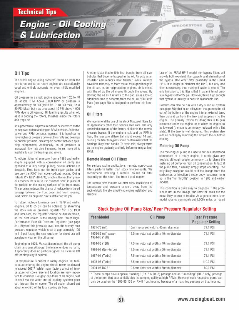
Oil TipsThe stock engine oiling systems found on both the non-turbo and turbo rotary engines are exceptionally good and entirely adequate for even mildly modified engines.
Oil pressure in a stock engine ranges from 20 to 40 psi at idle RPM. Above 3,000 RPM oil pressure is approximately 70 PSI (1993-95 - 110 PSI max, RX-8 80 PSI Max), but may drop about 10 PSI above 4,000 RPM due to oil foaming. Oil foaming results when oil, as it is cooling the rotors, thrashes inside the rotors and traps air.
As a general rule, oil pressure should be increased as the horsepower output and engine RPM increase. As horse-power and RPM demands increase, it is beneficial to have higher oil pressure between the shafts and bearings to prevent possible catastrophic contact between spin-ning components. Additionally, as oil pressure is increased, flow rate also increases; hence, more oil is available to cool the bearings and rotors.
To obtain higher oil pressure from a 1995 and earlier engine equipped with a conventional oil pump (as opposed to a “dry sump” pump), several actions are desirable. First, leave out the front cover gasket, and use only the RX-7 front cover-to-front housing O-ring (Mazda P/N N231-10-174), which is thicker than previ-ous models. Be sure to use “silicone seal” in place of the gaskets on the sealing surfaces of the front cover. This process reduces the chance of leakage from the oil passage between the front cover and front housing. Next, select an oil pump size suitable for the job.
For street high-performance use in 1979 and earlier engines, 80 to 85 psi can be obtained by shimming the stock rear oil pressure regulator 8”. For 1980 and later cars, the regulator cannot be disassembled, so the best choice is the Racing Beat Street High-Performance Rear Oil Pressure Regulator (see page 54). Beyond this pressure level, use the factory race pressure regulator, which is set at approximately 105 to 115 psi. Using the race regulator for street use will accelerate wear on the oil pump.
Beginning in 1979, Mazda discontinued the oil pump chain tensioner. Although the tensioner does no harm, it apparently does no particular good, so it can be left off for simplicity if desired.
Oil temperature is critical in rotary engines. Oil tem-perature entering the engine should never be allowed to exceed 205°F. While many factors affect oil tem-perature, oil cooler size and location are very impor-tant to consider. Roughly one-third of all engine heat rejected via the water and oil cooling systems goes out through the oil cooler. The oil cooler should get about one-third of the total cooling air flow.
Another factor that inhibits heat transfer from oil is air bubbles that become trapped in the oil. Air acts as an insulator and reduces heat transfer. While rotaries have little tendency to foam the oil through windage in the oil pan, as do reciprocating engines, air is mixed with the oil as the oil moves through the rotors. By slowing the oil as it returns to the pan, air is allowed additional time to separate from the oil. Our Oil Baffle Plate (see page 55) is designed to perform this func-tion.
Oil Filters
We recommend the use of the stock Mazda oil filters for all applications other than serious race cars. The only undesirable feature of the factory oil filter is the internal pressure bypass. If the engine is cold and the RPM is high, the pressure differential might exceed 14 psi., causing the filter to bypass some contaminants that the bearings likely can't handle. To avoid this, always warm up the engine gradually and fully before running at high RPM.
Remote Mount Oil Filters
For serious racing applications, remote, non-bypass filters perform better than stock filters/mounts. We recommend installing a remote, double oil filter assembly on the return line from the oil cooler.
The remote filter mounts we offer allow installation of temperature and pressure senders away from the engine block, thereby simplifying engine installation and removal.
Use of the FRAM HP-2 model non-bypass filters will provide both excellent filter capacity and elimination of the bypass. One other filter possibility is the FRAM HP-6. It is larger in diameter the HP-2, but only one filter is necessary, thus making it easier to mount. The only limitation to this filter is that it has an internal pres-sure bypass set for 22 psi. However, this is high enough that bypass is unlikely to occur in reasonable use.
Rotaries can also be run with a dry sump oil system (see page 55); that is, an oil system that pumps the oil out of the bottom of the engine into an external tank, then picks it up from the tank and supplies it to the engine. The primary reason for doing this is to gain clearance under the engine, or to allow the engine to be lowered (the pan is commonly replaced with a flat plate). If the tank is well designed, this system also aids oil cooling by removing the air from the oil before cooling.
Metering Oil Pump
The metering oil pump is a useful but misunderstood component of a rotary engine. It rarely gives any trouble, although people commonly try to blame the metering oil pump for high oil consumption. In fact, if the pump fails, it usually simply stops operating. The only likely exception would be if the linkage from the carburetor, or injection throttle body, becomes hung up in the “full throttle” position in 1988 and earlier models.
This condition is quite easy to diagnose. If the prob-lem is not in the linkage, the rotor oil seals are the most likely source of trouble. As a general note, later model rotaries commonly get 2,000+ miles per quart
www.racingbeat.com51
Year/Model Oil Pump Rear Pressure Regulator Setting1971-75 (All) 15mm rotor set width x 40mm diameter 71.1 PSI
1976-85 (All) except- 12.5mm rotor set width x 40mm diameter 71.1 PSI 1984-85 (13B)
1984-85 (13B) 17.5mm rotor set width x 40mm diameter 71.1 PSI
1986-92 (Non-turbo) 12.5mm rotor set width x 50mm diameter 71.1 PSI
1987-91 (Turbo) 17.5mm rotor set width x 50mm diameter 71.1 PSI
1993-95 (Turbo)* 17.5mm rotor set width x 50mm diameter 110.0 PSI
2004-05 RX-8* 12.5mm rotor set width x 50mm diameter 80.0 PSI
* These pumps have a special “loading” (RX-7 & RX-8) passage and an “unloading” (RX-8 only) passage at the bottom that substantially aids its pumping ability at high RPM’s. However, each respective pump can only be used on the 1993-95 13B or RX-8 front housing because of a matching passage on that housing.
Stock Engine Oil Pump Size/ Rear Pressure Regulator Setting
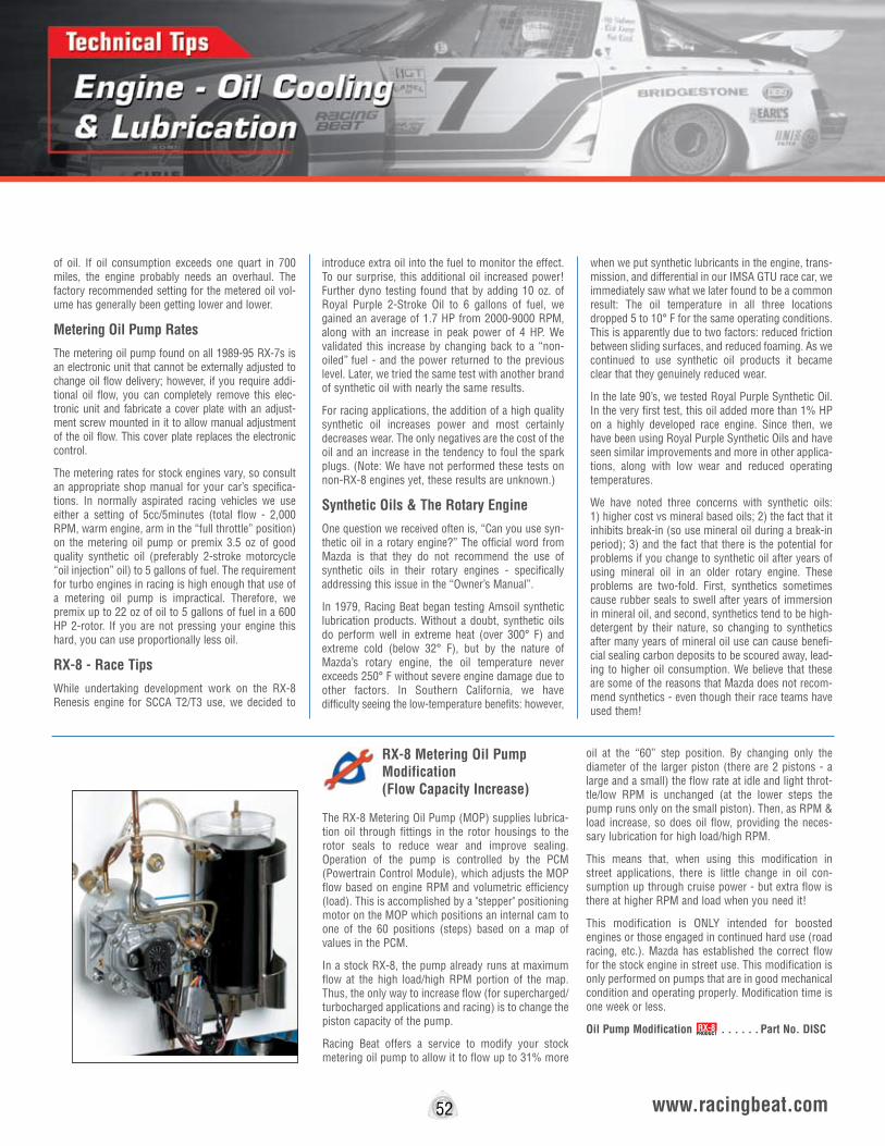
of oil. If oil consumption exceeds one quart in 700 miles, the engine probably needs an overhaul. The factory recommended setting for the metered oil vol-ume has generally been getting lower and lower.
Metering Oil Pump Rates
The metering oil pump found on all 1989-95 RX-7s is an electronic unit that cannot be externally adjusted to change oil flow delivery; however, if you require addi-tional oil flow, you can completely remove this elec-tronic unit and fabricate a cover plate with an adjust-ment screw mounted in it to allow manual adjustment of the oil flow. This cover plate replaces the electronic control.
The metering rates for stock engines vary, so consult an appropriate shop manual for your car’s specifica-tions. In normally aspirated racing vehicles we use either a setting of 5cc/5minutes (total flow - 2,000 RPM, warm engine, arm in the “full throttle” position) on the metering oil pump or premix 3.5 oz of good quality synthetic oil (preferably 2-stroke motorcycle “oil injection” oil) to 5 gallons of fuel. The requirement for turbo engines in racing is high enough that use of a metering oil pump is impractical. Therefore, we premix up to 22 oz of oil to 5 gallons of fuel in a 600 HP 2-rotor. If you are not pressing your engine this hard, you can use proportionally less oil.
RX-8 - Race Tips
While undertaking development work on the RX-8 Renesis engine for SCCA T2/T3 use, we decided to
introduce extra oil into the fuel to monitor the effect. To our surprise, this additional oil increased power! Further dyno testing found that by adding 10 oz. of Royal Purple 2-Stroke Oil to 6 gallons of fuel, we gained an average of 1.7 HP from 2000-9000 RPM, along with an increase in peak power of 4 HP. We validated this increase by changing back to a “non-oiled” fuel - and the power returned to the previous level. Later, we tried the same test with another brand of synthetic oil with nearly the same results.
For racing applications, the addition of a high quality synthetic oil increases power and most certainly decreases wear. The only negatives are the cost of the oil and an increase in the tendency to foul the spark plugs. (Note: We have not performed these tests on non-RX-8 engines yet, these results are unknown.)
Synthetic Oils & The Rotary Engine
One question we received often is, “Can you use syn-thetic oil in a rotary engine?” The official word from Mazda is that they do not recommend the use of synthetic oils in their rotary engines - specifically addressing this issue in the “Owner’s Manual”.
In 1979, Racing Beat began testing Amsoil synthetic lubrication products. Without a doubt, synthetic oils do perform well in extreme heat (over 300° F) and extreme cold (below 32° F), but by the nature of Mazda’s rotary engine, the oil temperature never exceeds 250° F without severe engine damage due to other factors. In Southern California, we have difficulty seeing the low-temperature benefits: however,
when we put synthetic lubricants in the engine, trans-mission, and differential in our IMSA GTU race car, we immediately saw what we later found to be a common result: The oil temperature in all three locations dropped 5 to 10° F for the same operating conditions. This is apparently due to two factors: reduced friction between sliding surfaces, and reduced foaming. As we continued to use synthetic oil products it became clear that they genuinely reduced wear.
In the late 90’s, we tested Royal Purple Synthetic Oil. In the very first test, this oil added more than 1% HP on a highly developed race engine. Since then, we have been using Royal Purple Synthetic Oils and have seen similar improvements and more in other applica-tions, along with low wear and reduced operating temperatures.
We have noted three concerns with synthetic oils: 1) higher cost vs mineral based oils; 2) the fact that it inhibits break-in (so use mineral oil during a break-in period); 3) and the fact that there is the potential for problems if you change to synthetic oil after years of using mineral oil in an older rotary engine. These problems are two-fold. First, synthetics sometimes cause rubber seals to swell after years of immersion in mineral oil, and second, synthetics tend to be high-detergent by their nature, so changing to synthetics after many years of mineral oil use can cause benefi-cial sealing carbon deposits to be scoured away, lead-ing to higher oil consumption. We believe that these are some of the reasons that Mazda does not recom-mend synthetics - even though their race teams have used them!
52 www.racingbeat.com
RX-8 Metering Oil Pump Modification (Flow Capacity Increase)
The RX-8 Metering Oil Pump (MOP) supplies lubrica-tion oil through fittings in the rotor housings to the rotor seals to reduce wear and improve sealing. Operation of the pump is controlled by the PCM (Powertrain Control Module), which adjusts the MOP flow based on engine RPM and volumetric efficiency (load). This is accomplished by a "stepper" positioning motor on the MOP which positions an internal cam to one of the 60 positions (steps) based on a map of values in the PCM.
In a stock RX-8, the pump already runs at maximum flow at the high load/high RPM portion of the map. Thus, the only way to increase flow (for supercharged/turbocharged applications and racing) is to change the piston capacity of the pump.
Racing Beat offers a service to modify your stock metering oil pump to allow it to flow up to 31% more
oil at the “60” step position. By changing only the diameter of the larger piston (there are 2 pistons - a large and a small) the flow rate at idle and light throt-tle/low RPM is unchanged (at the lower steps the pump runs only on the small piston). Then, as RPM & load increase, so does oil flow, providing the neces-sary lubrication for high load/high RPM.
This means that, when using this modification in street applications, there is little change in oil con-sumption up through cruise power - but extra flow is there at higher RPM and load when you need it!
This modification is ONLY intended for boosted engines or those engaged in continued hard use (road racing, etc.). Mazda has established the correct flow for the stock engine in street use. This modification is only performed on pumps that are in good mechanical condition and operating properly. Modification time is one week or less.
Oil Pump Modification . . . . . . Part No. DISCRX-8PRODUCT
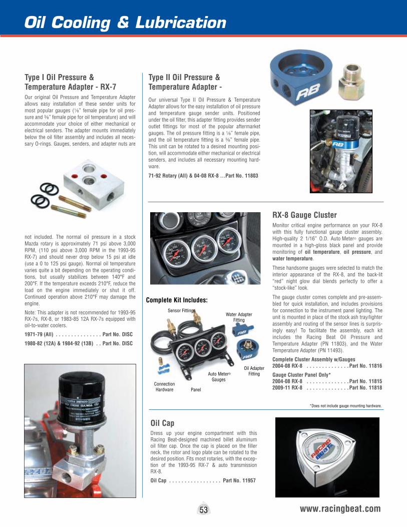
Oil Cooling & Lubrication
Type I Oil Pressure & Temperature Adapter - RX-7Our original Oil Pressure and Temperature Adapter allows easy installation of these sender units for most popular gauges (8” female pipe for oil pres-sure and a” female pipe for oil temperature) and will accommodate your choice of either mechanical or electrical senders. The adapter mounts immediately below the oil filter assembly and includes all neces-sary O-rings. Gauges, senders, and adapter nuts are
not included. The normal oil pressure in a stock Mazda rotary is approximately 71 psi above 3,000 RPM, (110 psi above 3,000 RPM in the 1993-95 RX-7) and should never drop below 15 psi at idle (use a 0 to 125 psi gauge). Normal oil temperature varies quite a bit depending on the operating condi-tions, but usually stabilizes between 140°F and 200°F. If the temperature exceeds 210°F, reduce the load on the engine immediately or shut it off. Continued operation above 210°F may damage the engine.
Note: This adapter is not recommended for 1993-95 RX-7s, RX-8, or 1983-85 12A RX-7s equipped with oil-to-water coolers.
1971-79 (All) . . . . . . . . . . . . . . . Part No. DISC
1980-82 (12A) & 1984-92 (13B) . . Part No. DISC
53 www.racingbeat.com
Type II Oil Pressure & Temperature Adapter - Our universal Type II Oil Pressure & Temperature Adapter allows for the easy installation of oil pressure and temperature gauge sender units. Positioned under the oil filter, this adapter fitting provides sender outlet fittings for most of the popular aftermarket gauges. The oil pressure fitting is a 8” female pipe, and the oil temperature fitting is a a” female pipe. This unit can be rotated to a desired mounting posi-tion, will accommodate either mechanical or electrical senders, and includes all necessary mounting hard-ware.
71-92 Rotary (All) & 04-08 RX-8 ...Part No. 11803
RX-8 Gauge ClusterMonitor critical engine performance on your RX-8 with this fully functional gauge cluster assembly. High-quality 2 1/16” O.D. Auto Meter® gauges are mounted in a high-gloss black panel and provide monitoring of oil temperature, oil pressure, and water temperature.
These handsome gauges were selected to match the interior appearance of the RX-8, and the back-lit “red” night glow dial blends perfectly to offer a “stock-like” look.
The gauge cluster comes complete and pre-assem-bled for quick installation, and includes provisions for connection to the instrument panel lighting. The unit is mounted in place of the stock ash tray/lighter assembly and routing of the sensor lines is surpris-ingly easy! To facilitate the assembly, each kit includes the Racing Beat Oil Pressure and Temperature Adapter (PN 11803), and the Water Temperature Adapter (PN 11493).
Complete Cluster Assembly w/Gauges 2004-08 RX-8 . . . . . . . . . . . . . .Part No. 11816
Gauge Cluster Panel Only* 2004-08 RX-8 . . . . . . . . . . . . . .Part No. 11815 2009-11 RX-8 . . . . . . . . . . . . . .Part No. 11818
Oil CapDress up your engine compartment with this Racing Beat-designed machined billet aluminum oil filter cap. Once the cap is placed on the filler neck, the rotor and logo plate can be rotated to the desired position. Fits most rotaries, with the excep-tion of the 1993-95 RX-7 & auto transmission RX-8.
Oil Cap . . . . . . . . . . . . . . . . . Part No. 11957
*Does not include gauge mounting hardware.
Complete Kit Includes:
Water Adapter Fitting
Oil Adapter Fitting Auto Meter®
Gauges
Panel
Sensor Fittings
Connection Hardware
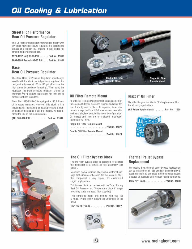
Oil Cooling & Lubrication
54 www.racingbeat.com
Street High Performance Rear Oil Pressure RegulatorThis Oil Pressure Regulator interchanges exactly with any stock rear oil pressure regulator. It is designed to bypass at a higher PSI, making it well suited for street high performance use.
1971-1992 (All) 80-85 PSI . . . . . . Part No. 11810
2004-2008 Renesis 90-95 PSI . . . . Part No. 11811
Thermal Pellet Bypass ReplacementThe Racing Beat thermal pellet bypass replacement can be installed on all 1986 and later (including RX-8) eccentric shafts to eliminate the stock pellet bypass, a source of possible failure under racing conditions.
1986-2011 (All) . . . . . . . . . . . . . . Part No. 11800
Oil Filter Remote MountAn Oil Filter Remote Mount simplifies replacement of the stock oil filter for clearance reasons and allow the use of non-bypass oil filters. As supplied, these filter mounts accept the Fram HP-1 or equivalent. Available in either a single or double filter mount configuration. Oil filter(s) and lines are not included. Inlet/outlet fittings are 2” NPT.
Single Oil Filter Remote Mount . . . . . . . . . . . . . . . . . . . . . . . . . Part No. 11820
Double Oil Filter Remote Mount . . . . . . . . . . . . . . . . . . . . . . . . . Part No. 11821
The Oil Filter Bypass BlockThe Oil Filter Bypass Block is designed to facilitate the installation of a remote oil filter assembly (see above).
Machined from aluminum-alloy with an internal pas-sage that eliminates the need for the stock oil filter, this component is very popular for customized engine applications.
This bypass block can be used with the Type I Racing Beat Oil Pressure and Temperature block if longer mounting studs are used. (Not supplied)
This simple-to-install unit comes with two (2) O-rings. (Photo below shows the underside of the unit.)
1971-95 RX-7 (All) . . . . . . . . . . Part No. 11822
Race Rear Oil Pressure RegulatorThe Race Rear Oil Pressure Regulator interchanges exactly with the stock rear oil pressure regulator. It is designed to bypass at 105 to 115 psi. (Pressure this high should be used only for racing). When using this regulator, the front pressure regulator should be shimmed 8” to ensure that it does not limit the oil pressure (shims included).
Note: The 1993-95 RX-7 is equipped a 110 PSI rear oil pressure regulator. However, this stock unit is inadequate at maintaining constant pressure at high-er loads. If the engine is used for racing, we recom-mend the use of the race regulator.
(All) 105-110 PSI . . . . . . . . . . . Part No. 11812
Double Oil Filter Remote Mount
Single Oil Filter Remote Mount
Mazda® Oil FilterWe offer the genuine Mazda OEM replacement filter for all rotary applications.
(All Rotary Applications) . . . . . . . Part No. 11958
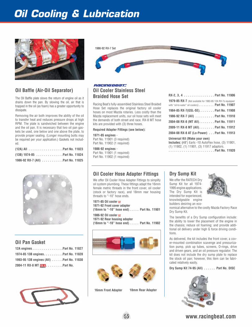
Section
55 www.racingbeat.com
Oil Baffle (Air-Oil Separator) The Oil Baffle plate slows the return of engine oil as it drains down the pan. By slowing the oil, air that is trapped in the oil (as foam) has a greater opportunity to dissipate.
Removing the air both improves the ability of the oil to transfer heat and reduces pressure drops at high RPM. The plate is sandwiched between the engine and the oil pan. It is necessary that two oil pan gas-kets be used, one below and one above the plate, to provide proper sealing. (Longer mounting bolts may be required per your application.) Gaskets not includ-ed.
(12A) All . . . . . . . . . . . . . . . . . .Part No. 11823
(13B) 1974-85 . . . . . . . . . . . . . .Part No. 11824
1986-92 RX-7 (All) . . . . . . . . . . .Part No. 11825
Oil Pan Gasket12A engines . . . . . . . . . . . . . . . .Part No. 11827
1974-85 13B engines . . . . . . . . . .Part No. 11828
1993-95 13B engines (All) . . . . . .Part No. 11830
2004-11 RX-8 MT . . . . . . . . . . . .Part No.
Oil Cooler Stainless Steel Braided Hose SetRacing Beat’s fully-assembled Stainless Steel Braided Hose Set replaces the original factory oil cooler hoses on most Mazda rotaries. Less costly than the Mazda replacement units, our oil hose sets will meet the demands of both street and race. RX-8 MT hose kits are provided with (3) three hoses.
Required Adapter Fittings (see below):
1971-85 engines - Part No. 11901 (3 required) Part No. 11902 (1 required)
1986-92 engines - Part No. 11901 (1 required) Part No. 11902 (1 required)
RX-2, 3, 4 . . . . . . . . . . . . . . . . Part No. 11906
1979-85 RX-7 (Not available for 1983-85 12A RX-7s equipped
with “oil-to-water” oil coolers) . . . . . . . . . Part No. 11907
1984-85 RX-7(GSL-SE). . . . . . . . Part No. 11908
1986-92 RX-7 (All) . . . . . . . . . . Part No. 11910
2004-08 RX-8 (MT All) . . . . . . . . Part No. 11911
2009-11 RX-8 MT (All) . . . . . . . . Part No. 11912
2004-08 RX-8 AT (Lo-Power) . . . Part No. 11913
Universal Kit (Make your own) Includes: (48") Earls -10 AutoFlex hose, (3) 11901, (1) 11902, (1) 11901, (3) 11917 adaptors. . . . . . . . . . . . . . . . . . . . . . . . . Part No. 11920
Oil Cooler Hose Adapter FittingsWe offer Oil Cooler Hose Adapter Fittings to simplify oil system plumbing. These fittings adapt the 16mm female metric threads in the front cover, oil cooler (stock or factory race), and 18mm rear housing threads to “-10” hose ends.
1971-85 Oil cooler or 1971-92 Front cover adapter (16mm to “-10” hose end) . . . . . Part No. 11901
1986-92 Oil cooler or 1971-92 Rear housing adapter (18mm to “-10” hose end) . . . . . Part No. 11902
18mm Rear Adapter16mm Front Adapter
Oil Cooling & Lubrication
Dry Sump KitWe offer the RATECH Dry Sump Kit for all 1974-1995 engine applications. The Dry Sump Kit is intended for experienced, knowledgeable engine builders desiring an eco-nomical alternative to the costly Mazda Factory Race Dry Sump Kit.
The benefits of a Dry Sump configuration include: the ability to lower the placement of the engine in the chassis; reduce oil foaming; and provide addi-tional oil delivery under high G force driving condi-tions.
As delivered, the kit includes the front cover, a cov-er-mounted combination scavenge and pressuriza-tion pump, pick up tubes, screens, O-rings, drive and driven gears, and an oil pressure regulator. The kit does not include the dry sump plate to replace the stock oil pan; however, this item can be fabri-cated relatively easily.
Dry Sump Kit 74-95 (All) . . . . . . Part No. DISCRX-8
PRODUCT
1986-92 RX-7 Set

Oil Cooling & Lubrication
Royal Purple Synthetic LubricantsRacing Beat has been recommending the use of synthetic oils in rotary applications for many years. Our research has found that synthetic oils provide superior friction reduction between sliding surfaces, reduced foaming, and lower oil temperatures. We have tested several different synthetic oils and have found that while most offered improved wear and lower oil temperatures, none offered any significant horsepower gains... except for Royal Purple!
Other professional engine builders have confirmed that Royal Purple Synthetic Racing Oil delivers meas-urable horsepower gains. Independent dyno tests show increases up to 5% (on smaller displacement engines) with nothing more than an oil change. Our in-house testing has yielded up to a 2% performance increase after changing from mineral-based oil to Royal Purple Synthetic Motor Oil.
Royal Purple incorporates Synerlec, a proprietary ingredient that coats an ultra-slick film on internal engine components to significantly reduce power-robbing friction.
Synthetic OEM Motor OilSpecially formulated SAE grades for use in stock and performance applications.
5W20 (per qt) . . . . . . . . . . . . . . . Part No. 1195610W30 (per qt) . . . . . . . . . . . . . . Part No. 1195910W40 (per qt) . . . . . . . . . . . . . . Part No. 1196020W50 (per qt) . . . . . . . . . . . . . . Part No. 119615W30 (per qt) . . . . . . . . . . . . . . . Part No. 11962
Synthetic OEM Racing OilFormulated for the maximum performance and pro-tection.
XPR (per qt) (5W30) . . . . . . . . . . Part No. 11963XPR (per qt) (10W40) . . . . . . . . . Part No. 11964XPR 51 (per qt) (20W50) . . . . . . . Part No. 11965
Synthetic Max-Gear OilMax-Gear reduces frictional wear and heat using impact absorbing, non-shearing molecular structure suitable for OEM, high performance, and race appli-cations.
75W90 Gear Lube (transmission and differential lube) (per qt) . . . . . . . Part No. 11966
Synthetic Two-Cycle Racing OilA clean burning, two-cycle pre-mix or injector oil.
Two-Cycle Oil (for use in race cars that pre-mix fuel and oil) (per qt) . . . . Part No. 11967
Synthetic Max-ATF Transmission FluidMax-ATF is fully compatible ATF that withstands extreme heat and provides long-life characteristics.
Automatic Transmission Fluid (exceeds requirements for both Ford and GM Dexron III)(per qt) . . . . . . . . . Part No. 11968
56 www.racingbeat.com
The Mazda Factory Race (MFR) Engine Oil PumpThe Mazda Factory Race Oil Pump interchanges exactly with the stock oil pump in all 1974-85 engines. The race oil pump rotor set width is 17.5mm, as opposed to 15mm in stock 1974-75 engines and 12.5mm in all 1976 and later engines, except the 1984-85 (13B). This pump is streetable, but is unnecessary for all but the most highly modified engines. The rotor sets in this pump are heat treated for long life.
1974-85 engines . . . . . . . . . . . . . Part No. DISC
RX-7 13B GSL-SE Oil Pan This RX-7 GSL-SE 13B Oil Pan is offered to assist you in the installation of a 1974-85 13B rotary in a 1979-85 RX-7 chassis.
We also offer a custom-made front motor mount that simplifies installation of a 13B into a “formerly 12A” chassis. (See page 39)
. . . . . . . . . . . . . . . . . . . . . . . . .Part No. 11831
RX-8 Protective Screens Provide your RX-8 with maximum protection against road hazard damage to the A/C condenser and the oil coolers with a set of Racing Beat protective screens. Produced from 304-grade stainless steel for exceptional durability and strength, these mesh screens will provide vital protec-tion to the critical cooling radiators on your RX-8.
Installation of these units can be easily undertaken with the removal of the RX-8 nose piece. Although this sounds like a daunting task, the removal of the nose can be easily accomplished in just a few minutes using only simple hand tools and following our step-by-step installation instructions.
A/C Condenser Screen 2004-052 . . . . Part No. 11805
Oil Cooler Screens (Per Screen) 04-08 . Part No. 11807 Oil Cooler Screens (Per Screen) 09-11 . Part No. 11808 (Manual Transmission cars - 2 screens required) (Automatic Transmission cars - 1 screen required)
Note: In late 2005, Mazda started supplying the RX-8 with a small lower “half-screen”. Although this screen appears to offer adequate protection, if you prefer 100% protection coverage you can remove the factory screen and install the Racing Beat unit.
Oil Cooler Screen
A/C Condenser Screen
Visit the Royal Purple website for a great FAQ page on the use of synthetic oil in the rotary engine! Visit www.royalpurple.com
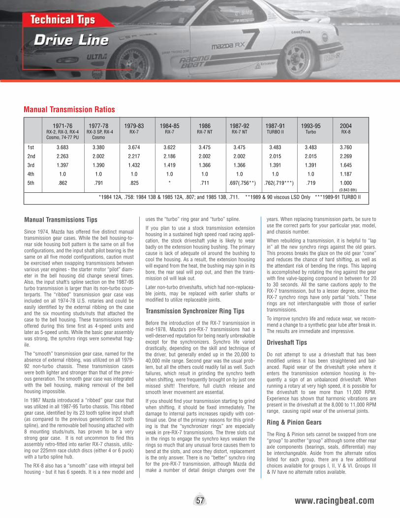
Manual Transmissions Tips
Since 1974, Mazda has offered five distinct manual transmission gear cases. While the bell housing-to-rear side housing bolt pattern is the same on all five configurations, and the input shaft pilot bearing is the same on all five model configurations, caution must be exercised when swapping transmissions between various year engines - the starter motor “pilot” diam-eter in the bell housing did change several times. Also, the input shaft’s spline section on the 1987-95 turbo transmission is larger than its non-turbo coun-terparts. The “ribbed” transmission gear case was included on all 1974-78 U.S. rotaries and could be easily identified by the external ribbing on the case and the six mounting studs/nuts that attached the case to the bell housing. These transmissions were offered during this time first as 4-speed units and later as 5-speed units. While the basic gear assembly was strong, the synchro rings were somewhat frag-ile.
The “smooth” transmission gear case, named for the absence of external ribbing, was utilized on all 1979-92 non-turbo chassis. These transmission cases were both lighter and stronger than that of the previ-ous generation. The smooth gear case was integrated with the bell housing, making removal of the bell housing impossible.
In 1987 Mazda introduced a “ribbed” gear case that was utilized in all 1987-95 Turbo chassis. This ribbed gear case, identified by its 23 tooth spline input shaft (as compared to the previous generations 22 tooth spline), and the removable bell housing attached with 8 mounting studs/nuts, has proven to be a very strong gear case. It is not uncommon to find this assembly retro-fitted into earlier RX-7 chassis, utiliz-ing our 225mm race clutch discs (either 4 or 6 puck) with a turbo spline hub.
The RX-8 also has a “smooth” case with integral bell housing - but it has 6 speeds. It is a new model and
uses the “turbo” ring gear and “turbo” spline.
If you plan to use a stock transmission extension housing in a sustained high speed road racing appli-cation, the stock driveshaft yoke is likely to wear badly on the extension housing bushing. The primary cause is lack of adequate oil around the bushing to cool the housing. As a result, the extension housing will expand from the heat, the bushing may spin in its bore, the rear seal will pop out, and then the trans-mission oil will leak out.
Later non-turbo driveshafts, which had non-replacea-ble joints, may be replaced with earlier shafts or modified to utilize replaceable joints.
Transmission Synchronizer Ring Tips
Before the introduction of the RX-7 transmission in mid-1978, Mazda’s pre-RX-7 transmissions had a well-deserved reputation for being nearly unbreakable except for the synchronizers. Synchro life varied drastically, depending on the skill and technique of the driver, but generally ended up in the 20,000 to 40,000 mile range. Second gear was the usual prob-lem, but all the others could readily fail as well. Such failures, which result in grinding the synchro teeth when shifting, were frequently brought on by just one missed shift! Therefore, full clutch release and smooth lever movement are essential.
If you should find your transmission starting to grind when shifting, it should be fixed immediately. The damage to internal parts increases rapidly with con-tinual use. One of the primary reasons for this grind-ing is that the “synchronizer rings” are especially weak in pre-RX-7 transmissions. The three slots cut in the rings to engage the synchro keys weaken the rings so much that any unusual force causes them to bend at the slots, and once they distort, replacement is the only answer. There is no “better” synchro ring for the pre-RX-7 transmission, although Mazda did make a number of detail design changes over the
years. When replacing transmission parts, be sure to use the correct parts for your particular year, model, and chassis number.
When rebuilding a transmission, it is helpful to “lap in” all the new synchro rings against the old gears. This process breaks the glaze on the old gear “cone” and reduces the chance of hard shifting, as well as the attendant risk of bending the rings. This lapping is accomplished by rotating the ring against the gear with fine valve-lapping compound in between for 20 to 30 seconds. All the same cautions apply to the RX-7 transmission, but to a lesser degree, since the RX-7 synchro rings have only partial “slots.” These rings are not interchangeable with those of earlier transmissions.
To improve synchro life and reduce wear, we recom-mend a change to a synthetic gear lube after break in. The results are immediate and impressive.
Driveshaft Tips
Do not attempt to use a driveshaft that has been modified unless it has been straightened and bal-anced. Rapid wear of the driveshaft yoke where it enters the transmission extension housing is fre-quently a sign of an unbalanced driveshaft. When running a rotary at very high speed, it is possible for the driveshaft to see more than 11,000 RPM. Experience has shown that harmonic vibrations are present in the driveshaft at the 8,000 to 11,000 RPM range, causing rapid wear of the universal joints.
Ring & Pinion Gears
The Ring & Pinion sets cannot be swapped from one “group” to another “group” although some other rear axle components (bearings, seals, differential) may be interchangeable. Aside from the alternate ratios listed for each group, there are a few additional choices available for groups I, II, V & VI. Groups III & IV have no alternate ratios available.
57 www.racingbeat.com
1971-76 1977-78 1979-83 1984-85 1986 1987-92 1987-91 1993-95 2004 RX-2, RX-3, RX-4 RX-3 SP, RX-4 RX-7 RX-7 RX-7 NT RX-7 NT TURBO II Turbo RX-8 Cosmo, 74-77 PU Cosmo
1st 3.683 3.380 3.674 3.622 3.475 3.475 3.483 3.483 3.760
2nd 2.263 2.002 2.217 2.186 2.002 2.002 2.015 2.015 2.269
3rd 1.397 1.390 1.432 1.419 1.366 1.366 1.391 1.391 1.645
4th 1.0 1.0 1.0 1.0 1.0 1.0 1.0 1.0 1.187
5th .862 .791 .825 * .711 .697(.756**) .762(.719***) .719 1.000
*1984 12A, .758: 1984 13B & 1985 12A, .807; and 1985 13B, .711. **1989 & 90 viscous LSD Only ***1989-91 TURBO II
Manual Transmission Ratios
(0.843 6th)
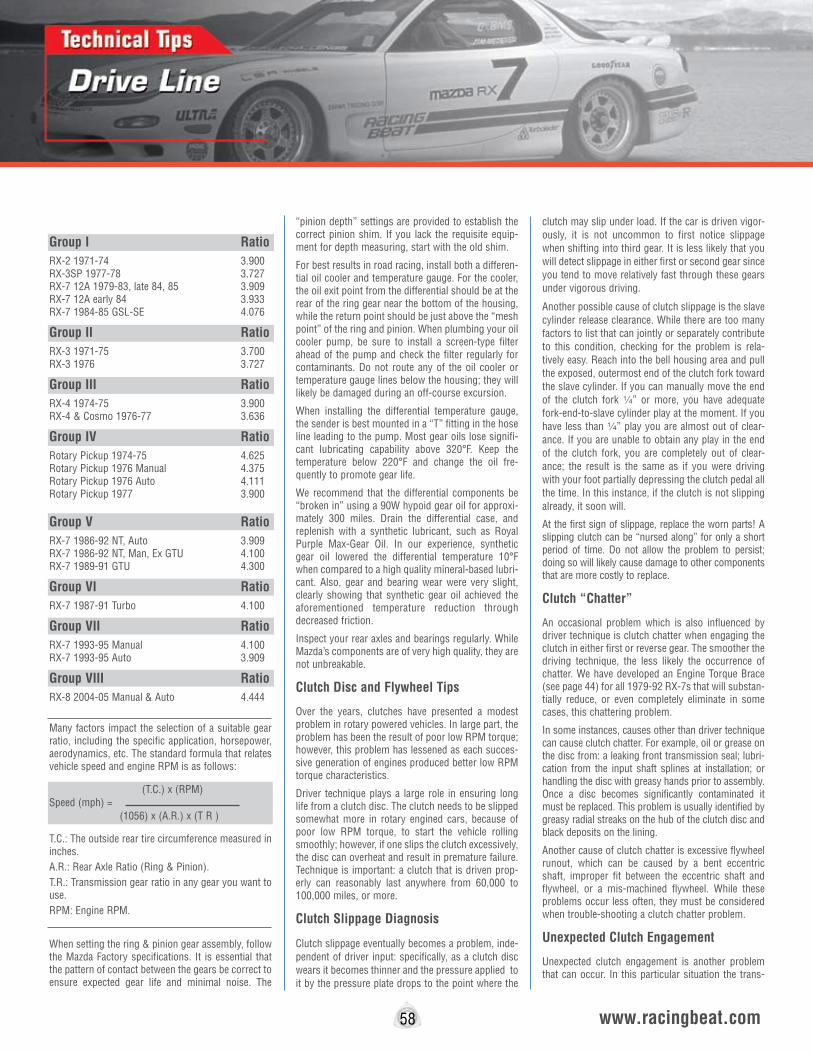
Group I RatioRX-2 1971-74 3.900 RX-3SP 1977-78 3.727 RX-7 12A 1979-83, late 84, 85 3.909 RX-7 12A early 84 3.933 RX-7 1984-85 GSL-SE 4.076
Group II RatioRX-3 1971-75 3.700 RX-3 1976 3.727
Group III RatioRX-4 1974-75 3.900 RX-4 & Cosmo 1976-77 3.636
Group IV RatioRotary Pickup 1974-75 4.625 Rotary Pickup 1976 Manual 4.375 Rotary Pickup 1976 Auto 4.111 Rotary Pickup 1977 3.900 Group V RatioRX-7 1986-92 NT, Auto 3.909 RX-7 1986-92 NT, Man, Ex GTU 4.100 RX-7 1989-91 GTU 4.300
Group VI RatioRX-7 1987-91 Turbo 4.100
Group VII RatioRX-7 1993-95 Manual 4.100 RX-7 1993-95 Auto 3.909
Group VIII RatioRX-8 2004-05 Manual & Auto 4.444
Many factors impact the selection of a suitable gear ratio, including the specific application, horsepower, aerodynamics, etc. The standard formula that relates vehicle speed and engine RPM is as follows:
Speed (mph) =
T.C.: The outside rear tire circumference measured in inches.A.R.: Rear Axle Ratio (Ring & Pinion).T.R.: Transmission gear ratio in any gear you want to use.RPM: Engine RPM.
When setting the ring & pinion gear assembly, follow the Mazda Factory specifications. It is essential that the pattern of contact between the gears be correct to ensure expected gear life and minimal noise. The
“pinion depth” settings are provided to establish the correct pinion shim. If you lack the requisite equip-ment for depth measuring, start with the old shim.
For best results in road racing, install both a differen-tial oil cooler and temperature gauge. For the cooler, the oil exit point from the differential should be at the rear of the ring gear near the bottom of the housing, while the return point should be just above the “mesh point” of the ring and pinion. When plumbing your oil cooler pump, be sure to install a screen-type filter ahead of the pump and check the filter regularly for contaminants. Do not route any of the oil cooler or temperature gauge lines below the housing; they will likely be damaged during an off-course excursion.
When installing the differential temperature gauge, the sender is best mounted in a “T” fitting in the hose line leading to the pump. Most gear oils lose signifi-cant lubricating capability above 320°F. Keep the temperature below 220°F and change the oil fre-quently to promote gear life.
We recommend that the differential components be “broken in” using a 90W hypoid gear oil for approxi-mately 300 miles. Drain the differential case, and replenish with a synthetic lubricant, such as Royal Purple Max-Gear Oil. In our experience, synthetic gear oil lowered the differential temperature 10°F when compared to a high quality mineral-based lubri-cant. Also, gear and bearing wear were very slight, clearly showing that synthetic gear oil achieved the aforementioned temperature reduction through decreased friction.
Inspect your rear axles and bearings regularly. While Mazda’s components are of very high quality, they are not unbreakable.
Clutch Disc and Flywheel Tips
Over the years, clutches have presented a modest problem in rotary powered vehicles. In large part, the problem has been the result of poor low RPM torque; however, this problem has lessened as each succes-sive generation of engines produced better low RPM torque characteristics.
Driver technique plays a large role in ensuring long life from a clutch disc. The clutch needs to be slipped somewhat more in rotary engined cars, because of poor low RPM torque, to start the vehicle rolling smoothly; however, if one slips the clutch excessively, the disc can overheat and result in premature failure. Technique is important: a clutch that is driven prop-erly can reasonably last anywhere from 60,000 to 100,000 miles, or more.
Clutch Slippage Diagnosis
Clutch slippage eventually becomes a problem, inde-pendent of driver input: specifically, as a clutch disc wears it becomes thinner and the pressure applied to it by the pressure plate drops to the point where the
clutch may slip under load. If the car is driven vigor-ously, it is not uncommon to first notice slippage when shifting into third gear. It is less likely that you will detect slippage in either first or second gear since you tend to move relatively fast through these gears under vigorous driving.
Another possible cause of clutch slippage is the slave cylinder release clearance. While there are too many factors to list that can jointly or separately contribute to this condition, checking for the problem is rela-tively easy. Reach into the bell housing area and pull the exposed, outermost end of the clutch fork toward the slave cylinder. If you can manually move the end of the clutch fork 4” or more, you have adequate fork-end-to-slave cylinder play at the moment. If you have less than 4” play you are almost out of clear-ance. If you are unable to obtain any play in the end of the clutch fork, you are completely out of clear-ance; the result is the same as if you were driving with your foot partially depressing the clutch pedal all the time. In this instance, if the clutch is not slipping already, it soon will.
At the first sign of slippage, replace the worn parts! A slipping clutch can be “nursed along” for only a short period of time. Do not allow the problem to persist; doing so will likely cause damage to other components that are more costly to replace.
Clutch “Chatter”
An occasional problem which is also influenced by driver technique is clutch chatter when engaging the clutch in either first or reverse gear. The smoother the driving technique, the less likely the occurrence of chatter. We have developed an Engine Torque Brace (see page 44) for all 1979-92 RX-7s that will substan-tially reduce, or even completely eliminate in some cases, this chattering problem.
In some instances, causes other than driver technique can cause clutch chatter. For example, oil or grease on the disc from: a leaking front transmission seal; lubri-cation from the input shaft splines at installation; or handling the disc with greasy hands prior to assembly. Once a disc becomes significantly contaminated it must be replaced. This problem is usually identified by greasy radial streaks on the hub of the clutch disc and black deposits on the lining.
Another cause of clutch chatter is excessive flywheel runout, which can be caused by a bent eccentric shaft, improper fit between the eccentric shaft and flywheel, or a mis-machined flywheel. While these problems occur less often, they must be considered when trouble-shooting a clutch chatter problem.
Unexpected Clutch Engagement
Unexpected clutch engagement is another problem that can occur. In this particular situation the trans-
www.racingbeat.com
(1056) x (A.R.) x (T R )
58
(T.C.) x (RPM)
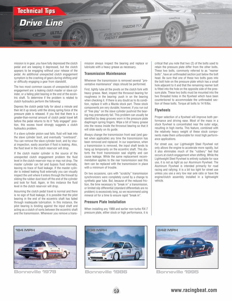
mission is in gear, you have fully depressed the clutch pedal and are keeping it depressed, but the clutch appears to be engaging without your release of the pedal. An additional unexpected clutch engagement symptom is the crashing of gears during shifting and/or difficulty engaging a gear from standstill.
The two most common causes of unexpected clutch engagement are: a leaking clutch master or slave cyl-inder, or a failing pilot bearing in the end of the eccen-tric shaft. To determine if the problem is related to clutch hydraulics perform the following:
Depress the clutch pedal fully for about a minute and then let it up slowly until the strong spring force of the pressure plate is released. If you find that there is a greater-than-normal amount of clutch pedal travel left before the pedal returns to its it “fully engaged” posi-tion, this excess travel strongly suggests a clutch hydraulics problem.
If a slave cylinder piston seal fails. fluid will leak into the slave cylinder boot, and eventually “overboard”. You can remove the slave cylinder boot, and by visu-al inspection, easily ascertain if fluid is leaking. Also, the fluid level in the clutch reservoir will drop.
If the clutch master cylinder is the source of the unexpected clutch engagement problem the fluid level in the clutch reservoir may or may not drop. The master cylinder can fail and bypass fluid internally, leaving no trace of fluid leakage. If the master cylin-der is indeed leaking fluid externally you can visually inspect the unit where it enters through the firewall by sliding the rubber dust boot off the end of the cylinder and look for fluid. Again, in this instance the fluid level in the clutch reservoir will drop.
Assuming the clutch pedal travel is normal and there is no sign of fluid leakage, it is possible that the pilot bearing in the end of the eccentric shaft has failed through inadequate lubrication. In this instance, the pilot bearing is binding against the input shaft and acting as a clutch of sorts between the eccentric shaft and the transmission. Whenever you remove a trans-
mission always inspect the bearing and replace or lubricate with a heavy grease as necessary.
Transmission Maintenance
Whenever the transmission is removed several “pre-ventative maintenance” steps should be performed.
First, lightly lube all the pivots on the clutch fork with heavy grease. Next, inspect the throwout bearing for roughness in the bearing: push in on the bearing when checking it. If there is any doubt as to its condi-tion, replace it with a Mazda stock part. These stock components are very durable; however, if you run out of “free play” on the slave cylinder pushrod the bear-ing may prematurely fail. This problem can usually be identified by deep grooves worn in the pressure plate diaphragm spring fingers. Wipe a bit of heavy grease into the recess inside the throwout bearing so that it will slide easily on its guide.
Always change the transmission front seal (and gas-ket when applicable) any time the transmission has been removed and replaced. In our experience, when a transmission is removed, the input shaft tends to hang up temporarily on the eccentric shaft. This dis-torts the front transmission seal slightly and can cause leakage. While the same replacement recom-mendation applies to the rear transmission seal this item can be replaced with the transmission in place with a minimum of trouble.
On two occasions, cars with “scratchy” transmission synchronizers were completely cured by a change to synthetic gear lube. But, because of the reduced fric-tion, the time necessary to “break in” a transmission, or limited slip differential (standard differentials are no problem) is excessively long, so we recommend using mineral oil for a time to ensure rapid “break in”.
Pressure Plate Installation
When installing any 1988 and earlier non-turbo RX-7 pressure plate, either stock or high performance, it is
critical that you note that two (2) of the bolts used to retain the pressure plate differ from the other bolts. These two bolts, commonly referred to as “reamer bolts”, have an unthreaded section just below the bolt head. Be sure that one of these two bolts goes into the bolt hole on the pressure plate which has a small hole adjacent to it and that the remaining reamer bolt is fitted into the hole on the opposite side of the pres-sure plate. These two bolts must be mounted into the two threaded holes in the flywheel which have been counterbored to accommodate the unthreaded sec-tion of these bolts. Torque all bolts to 14 ft/lbs.
Flywheels
Proper selection of a flywheel will improve both per-formance and driving ease. Most of the mass in a stock flywheel is concentrated near the outer edge, resulting in high inertia. This feature, combined with the relatively heavy weight of these stock compo-nents make them unfavorable for most high perform-ance applications.
For street use, our Lightweight Steel Flywheel not only allows the engine to accelerate more rapidly, but it also eliminates much of the “rubbery” feel that occurs at clutch engagement when shifting. While the Lightweight Steel Flywheel is entirely suitable for race use, it is not as light as our Aluminum Flywheel. The Aluminum Flywheel is intended primarily for road racing and rallying; it is a bit too light for street use unless you use a very low rear axle ratio or have the engine/clutch assembly installed in a lightweight vehicle.
59 www.racingbeat.com
Bonneville 1986 Bonneville 1995Bonneville 1978
184 MPH 238 MPH 242 MPH

Drive Line
Clutch Kits/Discs
60 www.racingbeat.com
WARNING: None of the Flywheel or Clutch components shown in this catalog should ever be allowed to exceed 10,500 RPM under any condition. This same RPM limit applies to stock components. You must use an engine RPM-limiter to prevent excessive RPM. If your engine is capable of exceeding 8,500 RPM you must install a transmission scatter shield, or “ballistic blanket”. Failure to implement the above may result in serious injury or even death.
Clutch Net Sport/Strip™ Heavy Duty Clutch Disc (Turbo)The Sport/Strip™ Heavy Duty (HD) Clutch Disc is designed for occasional street use and moderate drag or road racing use in Turbo II and 1993-95 Twin Turbo RX-7 chassis. The high yield/high burst strength performance linings are combined with a sprung hub configuration to produce very sharp engagement/disengagement characteristics, typically resulting in improved acceleration times. One of the most popular high performance discs we offer, this is the disc to choose if your stock disc has failed because of hard use.
The Sport/Strip Heavy Duty (HD) Clutch Disc interchanges exactly with the stock disc and can be used with the stock pres-sure plate or the Racing Beat Turbo II Street/Strip Pressure Plate.
1987-95 RX-7 Turbo - 240mm . . . . . . . . . . .Part No. 12508
Clutch Net Street/Strip™ Heavy Duty Clutch Disc (Non-Turbo)The Street/Strip™ Heavy Duty Clutch Disc is intended for high-performance streetable applications and for occasional drag or road racing applications. By eliminating the wavy marcel spring, incorporating additional attachment rivets, and utilizing high yield/high burst strength performance linings, the Street/Strip Heavy Duty Disc both engages and releases quickly, thereby improving acceleration times.
This disc is well suited for high output streetable engines and interchanges exactly with the stock disc. It can be used with a stock pressure plate, our Street/Strip™ Pressure Plate, or our Race Pressure Plate.
1971-82 (except rotary pickup) 215mm . . . . Part No. 12509
1983-92 RX-7 (12A & 13B 6-Port) 225mm . . Part No. 12510
Exedy Clutch KitsExedy Clutch is one world's largest supplier of both stock OEM and performance aftermarket clutch components. These complete Exedy clutch kits include a sprung hub clutch disc, upgraded pressure plate, replacement throw out bearing, pilot bearing, and a clutch installation alignment tool. These complete kits are ideally suited for street or modified vehicles, and drivability characteristics of kits supplied with organic material discs are similar to the stock clutch. Increased pres-sure plate clamping loads provide the necessary capacity to handle the performance demands of modified engines and spirited driving. Although pedal loads will be slightly higher because of the increased clamping load, many of these kits are well suited for use on daily-driven cars.
Racing Beat offers a wide selection of complete kits for applications range from street, track days, autocross, drag racing, etc...for more information regarding the appropriate kit for your application, contact Racing Beat or visit our website.
Complete Kit Applications:
1979-82Exedy OE Kit - 12A . . . . . . . . . . . . . . . . . . . . . . . . Part No. 12626
1983-92 RX-7Exedy Stage 1 Kit - 12A & 13B Non-turbo . . . . . . . . . Part No. 12641
Exedy Stage 2 Kit - 12A & 13B Non-turbo . . . . . . . . . Part No. 12642
Exedy Stage 1 Kit - Turbo II . . . . . . . . . . . . . . . . . . Part No. 12643
Exedy Stage 1 Kit HD - Turbo II . . . . . . . . . . . . . . . . Part No. 12643
Exedy Stage 1 Kit HD Ceramic - Turbo II . . . . . . . . . . Part No. 12644
Exedy Stage 2 Kit Ceramic - Turbo II . . . . . . . . . . . . Part No. 12644
1993-95 RX-7Exedy Stage 1 Kit . . . . . . . . . . . . . . . . . . . . . . . . . Part No. 12645
Exedy Stage 2 Kit Ceramic . . . . . . . . . . . . . . . . . . . Part No. 12647
2004-11 RX-8Exedy Stage 1 Kit 04-08 . . . . . . . . . . . . . . . . . . . . . Part No. 12650
Exedy Stage 1 Kit 09-11 . . . . . . . . . . . . . . . . . . . . . Part No. 12651
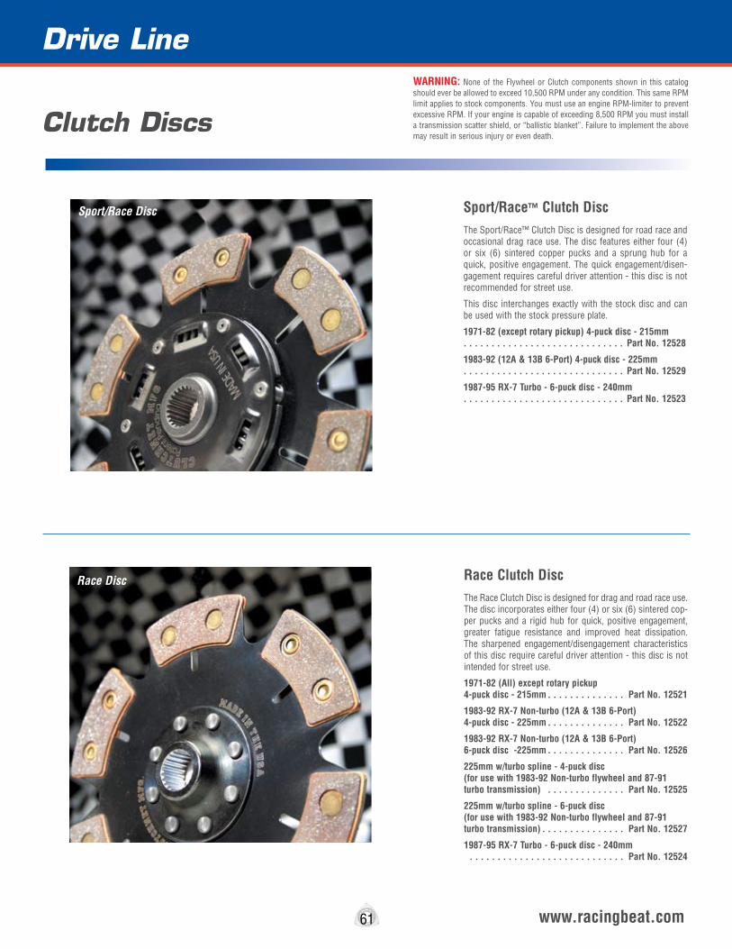
61 www.racingbeat.com
Sport/Race™ Clutch DiscThe Sport/Race™ Clutch Disc is designed for road race and occasional drag race use. The disc features either four (4) or six (6) sintered copper pucks and a sprung hub for a quick, positive engagement. The quick engagement/disen-gagement requires careful driver attention - this disc is not recommended for street use.
This disc interchanges exactly with the stock disc and can be used with the stock pressure plate.
1971-82 (except rotary pickup) 4-puck disc - 215mm . . . . . . . . . . . . . . . . . . . . . . . . . . . . . Part No. 12528
1983-92 (12A & 13B 6-Port) 4-puck disc - 225mm . . . . . . . . . . . . . . . . . . . . . . . . . . . . . Part No. 12529
1987-95 RX-7 Turbo - 6-puck disc - 240mm . . . . . . . . . . . . . . . . . . . . . . . . . . . . . Part No. 12523
Race Clutch DiscThe Race Clutch Disc is designed for drag and road race use. The disc incorporates either four (4) or six (6) sintered cop-per pucks and a rigid hub for quick, positive engagement, greater fatigue resistance and improved heat dissipation. The sharpened engagement/disengagement characteristics of this disc require careful driver attention - this disc is not intended for street use.
1971-82 (All) except rotary pickup 4-puck disc - 215mm . . . . . . . . . . . . . . Part No. 12521
1983-92 RX-7 Non-turbo (12A & 13B 6-Port) 4-puck disc - 225mm . . . . . . . . . . . . . . Part No. 12522
1983-92 RX-7 Non-turbo (12A & 13B 6-Port) 6-puck disc -225mm . . . . . . . . . . . . . . Part No. 12526
225mm w/turbo spline - 4-puck disc (for use with 1983-92 Non-turbo flywheel and 87-91 turbo transmission) . . . . . . . . . . . . . . Part No. 12525
225mm w/turbo spline - 6-puck disc (for use with 1983-92 Non-turbo flywheel and 87-91 turbo transmission) . . . . . . . . . . . . . . . Part No. 12527
1987-95 RX-7 Turbo - 6-puck disc - 240mm . . . . . . . . . . . . . . . . . . . . . . . . . . . . Part No. 12524
Drive Line
Clutch Discs
WARNING: None of the Flywheel or Clutch components shown in this catalog should ever be allowed to exceed 10,500 RPM under any condition. This same RPM limit applies to stock components. You must use an engine RPM-limiter to prevent excessive RPM. If your engine is capable of exceeding 8,500 RPM you must install a transmission scatter shield, or “ballistic blanket”. Failure to implement the above may result in serious injury or even death.
Sport/Race Disc
Race Disc
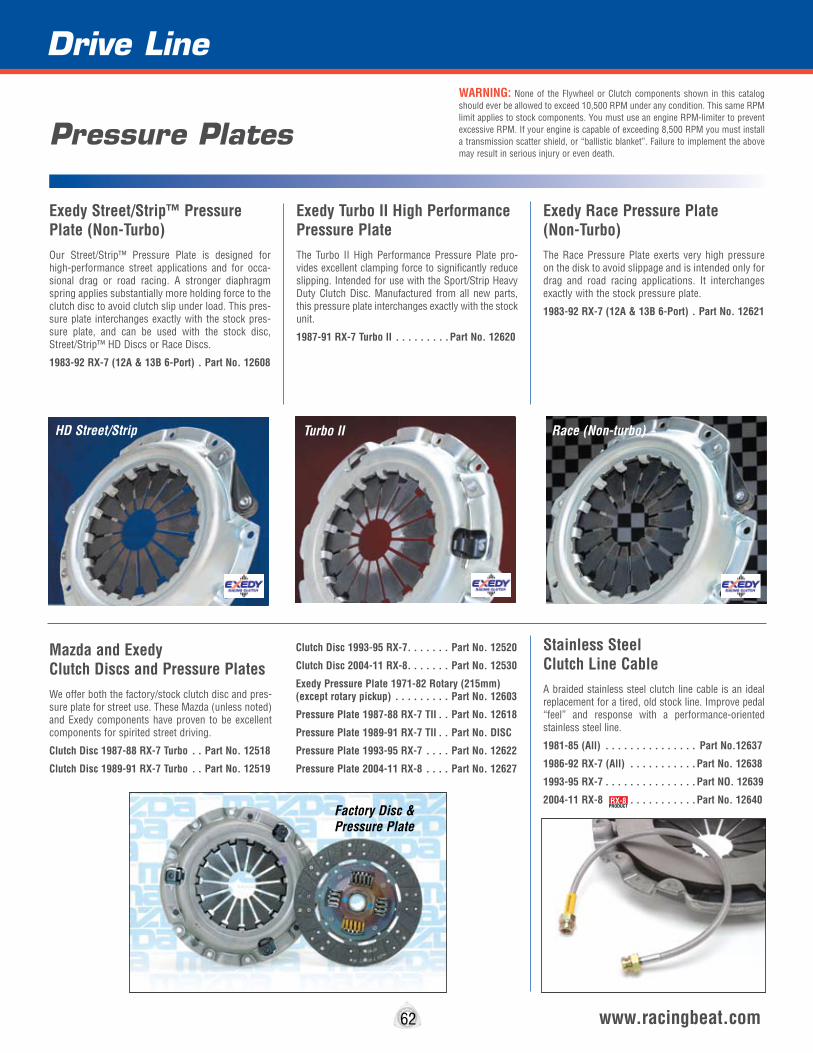
62 www.racingbeat.com
Exedy Street/Strip™ Pressure Plate (Non-Turbo)Our Street/Strip™ Pressure Plate is designed for high-performance street applications and for occa-sional drag or road racing. A stronger diaphragm spring applies substantially more holding force to the clutch disc to avoid clutch slip under load. This pres-sure plate interchanges exactly with the stock pres-sure plate, and can be used with the stock disc, Street/Strip™ HD Discs or Race Discs.
1983-92 RX-7 (12A & 13B 6-Port) . Part No. 12608
Exedy Turbo II High Performance Pressure PlateThe Turbo II High Performance Pressure Plate pro-vides excellent clamping force to significantly reduce slipping. Intended for use with the Sport/Strip Heavy Duty Clutch Disc. Manufactured from all new parts, this pressure plate interchanges exactly with the stock unit.
1987-91 RX-7 Turbo lI . . . . . . . . .Part No. 12620
Exedy Race Pressure Plate (Non-Turbo)The Race Pressure Plate exerts very high pressure on the disk to avoid slippage and is intended only for drag and road racing applications. It interchanges exactly with the stock pressure plate.
1983-92 RX-7 (12A & 13B 6-Port) . Part No. 12621
Pressure Plates
Mazda and Exedy Clutch Discs and Pressure PlatesWe offer both the factory/stock clutch disc and pres-sure plate for street use. These Mazda (unless noted) and Exedy components have proven to be excellent components for spirited street driving.
Clutch Disc 1987-88 RX-7 Turbo . . Part No. 12518
Clutch Disc 1989-91 RX-7 Turbo . . Part No. 12519
Clutch Disc 1993-95 RX-7 . . . . . . . Part No. 12520
Clutch Disc 2004-11 RX-8 . . . . . . . Part No. 12530
Exedy Pressure Plate 1971-82 Rotary (215mm) (except rotary pickup) . . . . . . . . . Part No. 12603
Pressure Plate 1987-88 RX-7 TII . . Part No. 12618
Pressure Plate 1989-91 RX-7 TII . . Part No. DISC
Pressure Plate 1993-95 RX-7 . . . . Part No. 12622
Pressure Plate 2004-11 RX-8 . . . . Part No. 12627
Stainless Steel Clutch Line CableA braided stainless steel clutch line cable is an ideal replacement for a tired, old stock line. Improve pedal “feel” and response with a performance-oriented stainless steel line.
1981-85 (All) . . . . . . . . . . . . . . . Part No.12637
1986-92 RX-7 (All) . . . . . . . . . . .Part No. 12638
1993-95 RX-7 . . . . . . . . . . . . . . .Part NO. 12639
2004-11 RX-8 . . . . . . . . . . . .Part No. 12640
Drive LineWARNING: None of the Flywheel or Clutch components shown in this catalog should ever be allowed to exceed 10,500 RPM under any condition. This same RPM limit applies to stock components. You must use an engine RPM-limiter to prevent excessive RPM. If your engine is capable of exceeding 8,500 RPM you must install a transmission scatter shield, or “ballistic blanket”. Failure to implement the above may result in serious injury or even death.
RX-8PRODUCT
HD Street/Strip
Factory Disc & Pressure Plate
Turbo II Race (Non-turbo)
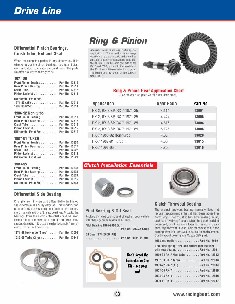
Clutch Throwout BearingThe original throwout bearing normally does not require replacement unless it has been abused in some way. However, if it has been making noise, such as a “whirring” sound when the clutch pedal is depressed, or if the slave linkage has run out of clear-ance, replacement is wise. Any roughness felt in the bearing after it is removed is cause for replacement. Our throwout bearing is a Mazda OEM part.
1978 and earlier . . . . . . . . . . . . . Part No.12610
Retaining spring 1978 and earlier (not included with new bearing) . . . . . . . . . . . . Part No. 12611
1979-88 RX-7 Non-turbo . . . . . . . Part No. 12612
1987-88 RX-7 Turbo lI . . . . . . . . . Part No. 12613
1989-92 RX-7 (All) . . . . . . . . . . . Part No. 12614
1993-95 RX-7 . . . . . . . . . . . . . . . Part No. 12615
2004-08 RX-8 . . . . . . . . . . . . . . . Part No. 12616
2009-11 RX-8 . . . . . . . . . . . . . . . Part No. 12617
Pilot Bearing & Oil SealReplace the pilot bearing and oil seal on your vehicle with these genuine Mazda OEM parts.
Pilot Bearing 1974-2006 (All) . . . . . . . . . . . . . . . . . . . . Part No. N326-11-D03
Oil Seal 1974-2006 (All) . . . . . . . . . . . . . . . . . . . . Part No. 1881-11-404
63 www.racingbeat.com
Alternate axle ratios are available for special applications. These ratios interchange exactly with the stock parts and should be adjusted to stock specifications. Note that the RX-3 SP uses the same gear sets as the RX-2 and RX-7, while all other models of the RX-3 have a different selection of gears. The pinion shaft is longer on the conven-tional RX-3
Differential Pinion Bearings, Crush Tube, Nut and SealWhen replacing the pinion in any differential, it is wise to replace the pinion bearings, locknut and seal, and mandatory to change the crush tube. The parts we offer are Mazda factory parts.
1971-85Front Pinion Bearing . . . . . . . . . . Part No. 13510 Rear Pinion Bearing . . . . . . . . . . Part No. 13511 Crush Tube . . . . . . . . . . . . . . . . . Part No. 13512 Pinion Locknut . . . . . . . . . . . . . . Part No. 13515
Differential Front Seal 1971-82 (All) . . . . . . . . . . . . . . . Part No. 13513 1983-85 RX-7 . . . . . . . . . . . . . . . Part No. 13514
1986-92 Non-turboFront Pinion Bearing . . . . . . . . . . Part No. 13510 Rear Pinion Bearing . . . . . . . . . . Part No. 13517 Crush Tube . . . . . . . . . . . . . . . . . Part No. 13518 Pinion Locknut . . . . . . . . . . . . . . Part No. 13515 Differential Front Seal . . . . . . . . . Part No. 13519
1987-91 TURBO IIFront Pinion Bearing . . . . . . . . . . Part No. 13530 Rear Pinion Bearing . . . . . . . . . . Part No. 13517 Crush Tube . . . . . . . . . . . . . . . . . Part No. 13522 Pinion Locknut . . . . . . . . . . . . . . Part No. 13515 Differential Front Seal . . . . . . . . . Part No. 13523
1993-95Front Pinion Bearing . . . . . . . . . . Part No. 13530 Rear Pinion Bearing . . . . . . . . . . Part No. 13531 Crush Tube . . . . . . . . . . . . . . . . Part No. 13532 Pinion Locknut . . . . . . . . . . . . . . Part No. 13515 Differential Front Seal . . . . . . . . Part No. 13533
RX-2, RX-3 SP, RX-7 1971-85 4.111 13001
RX-2, RX-3 SP, RX-7 1971-85 4.444 13005
RX-2, RX-3 SP, RX-7 1971-85 4.875 13004
RX-2, RX-3 SP, RX-7 1971-85 5.125 13006
RX-7 1986-92 Non-turbo 4.30 13020
RX-7 1987-91 Turbo II 4.30 13015
RX-7 1993-95 4.30 13016
Application Gear Ratio Part No.
Differential Side BearingChanging from the standard differential to the limited slip differential is a fairly easy job. This modification requires only a few special tools (consult the factory shop manual) and two (2) new bearings. Actually, the bearings from the stock differential could be used except that pulling them off is difficult and frequently causes damage. It is usually easier to simply “press” a new set on the limited slip.
1971-92 Non-turbo (2 req) . . . . . . Part No. 13509
1987-95 Turbo (2 req) . . . . . . . . . Part No. 13541
Ring & Pinion Gear Application Chart(See the chart on page 73 for stock gear ratios)
Clutch Installation Essentials
Ring & Pinion
Don't forget the Transmission Seal
Kit - see page 66!
Drive Line

Aluminum Flywheels
64 www.racingbeat.com
Racing Beat Aluminum Flywheel KitThe lightweight Racing Beat Aluminum Flywheel has a heat-treated steel friction surface for long life and excellent performance. Intended primarily for road racing and rallying, this kit reduces the flywheel weight up to 55 percent of the original, and reduces the flywheel inertia up to 80 percent of the original. The ring gear is bolted into place for security. The all the hardware necessary for installation, including special bolts which attach the pressure plate without modification. Review the table below to compare the stock flywheel with the applicable Racing Beat fly-wheel. Important Note: This flywheel requires the correct balance weight (not included) for installation, see below.
1974-82 12A RX-7 . . . . . . . . . . . .Part No. 114331983-92 12A & 13B Non-turbo . . .Part No. 114341987-95 Turbo & RX-8 . . . . . . . .Part No. 11435
Replacement Friction Plates:1974-92 Non-turbo . . . . . . . . . . .Part No.114311987-95 Turbo & RX-8 . . . . . . . .Part No.11432
Flywheel Weight Table
1974-80 30 lbs. 16 lbs. 12 lbs.
1981-85 RX-7 23 lbs. 16 lbs. 12 lbs.
1986-88 RX-7 (Non-turbo) 24 lbs. 17 lbs. 12 lbs.
1989-92 RX-7 (Non-turbo) 22 lbs. 17 lbs. 12 lbs.
1987-88 RX-7 (Turbo II ) 28 lbs. 17 lbs. 12 lbs.
1989-91 RX-7 (Turbo II ) 22 lbs. 17 lbs. 12 lbs.
1993-95 RX-7 19 lbs. 17 lbs. 12 lbs.
2004-11 RX-8 16.8 lbs. 12 lbs.
Year
Lightweight Steel
Flywheel*Aluminum Flywheel*
Stock Flywheel
*Includes counterweight
Rear CounterweightsAll automatic transmission-configured Mazda rotary engines are equipped
with a rear counterweight. The counterweight serves both as a critical engine balancing component and as an
attachment point for the automatic transmission flex plate. Racing
Beat includes these counter-weights with our lightweight steel and aluminum flywheels to maintain engine balance. We offer these counterweights separately for special projects. Mis-matching a counterweight to the wrong engine application
will result in engine damage and possible serious injury or death
. 1983-85 12A engines . . . . . . . . . . . . . . . . . . . . . . . . . . Part No. DISC1974-82 12A engines . . . . . . . . . . . . . . . . . . . . . . . . . . Part No. DISC1974-85 13B engines . . . . . . . . . . . . . . . . . . . . . . . . . Part No. 114611986-88 13B All . . . . . . . . . . . . . . . . . . . . . . . . . . . . . Part No. 114631989-95 13B All . . . . . . . . . . . . . . . . . . . . . . . . . . . . . Part No. 114662004-11 RX-8 . . . . . . . . . . . . . . . . . . . . . . . . . . . . Part No. 11458RX-8
PRODUCT
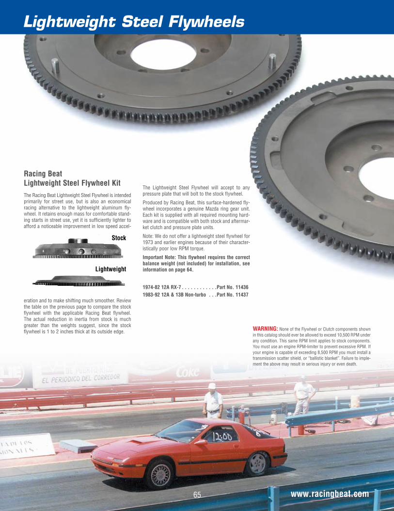
Racing Beat Lightweight Steel Flywheel KitThe Racing Beat Lightweight Steel Flywheel is intended primarily for street use, but is also an economical racing alternative to the lightweight aluminum fly-wheel. It retains enough mass for comfortable stand-ing starts in street use, yet it is sufficiently lighter to afford a noticeable improvement in low speed accel-
eration and to make shifting much smoother. Review the table on the previous page to compare the stock flywheel with the applicable Racing Beat flywheel. The actual reduction in inertia from stock is much greater than the weights suggest, since the stock flywheel is 1 to 2 inches thick at its outside edge.
The Lightweight Steel Flywheel will accept to any pressure plate that will bolt to the stock fIywheel.
Produced by Racing Beat, this surface-hardened fly-wheel incorporates a genuine Mazda ring gear unit. Each kit is supplied with all required mounting hard-ware and is compatible with both stock and aftermar-ket clutch and pressure plate units.
Note: We do not offer a lightweight steel flywheel for 1973 and earlier engines because of their character-istically poor low RPM torque.
Important Note: This flywheel requires the correct balance weight (not included) for installation, see information on page 64.
1974-82 12A RX-7 . . . . . . . . . . . .Part No. 114361983-92 12A & 13B Non-turbo . . .Part No. 11437
Stock
Lightweight
Lightweight Steel Flywheels
www.racingbeat.com
WARNING: None of the Flywheel or Clutch components shown in this catalog should ever be allowed to exceed 10,500 RPM under any condition. This same RPM limit applies to stock components. You must use an engine RPM-limiter to prevent excessive RPM. If your engine is capable of exceeding 8,500 RPM you must install a transmission scatter shield, or “ballistic blanket”. Failure to imple-ment the above may result in serious injury or even death.
65

Tool & Accessories
Drive Line
Automatic Transmission Balance Weight PullerThe Automatic Transmission Balance Weight Puller will remove any Mazda rotary automatic transmis-sion balance weight from its taper press fit on the eccentric shaft once the flywheel nut is loosened.
All rotaries . . . . . . . . . . . . . . . . Part No. 22003
66 www.racingbeat.com
Transmission Front Seal and Rear Seal KitWe recommend replacing the transmission front seal and rear seal kit when re-installing the transmission to reduce the risk of leakage. The primary reason for leaks seems to be the large loads that are placed on the input shaft when re-installing the transmission, when it is common to have to “hang” the transmis-sion on the input shaft at some point disturbing the seal. Hence, replacing the seals during re-installation is a wise idea. (Gasket included where applicable.)
1974-78 (All) . . . . . . . . . . . . . . . Part No. 12035
1979-88 RX-7 Non-turbo . . . . . . . Part No. 12036
1989-92 RX-7 Non-turbo . . . . . . . Part No. 12037
1987-88 RX-7 Turbo lI . . . . . . . . . Part No. 12038
1989-91 RX-7 Turbo Il . . . . . . . . . Part No. 12039
1993-95 RX-7 . . . . . . . . . . . . . . . Part No. 12040
2004-08 RX-8 . . . . . . . . . . . . . . . Part No. 12041
2009-11 RX-8 . . . . . . . . . . . . . . . Part No. 12042
Flywheel Nut WrenchThe Flywheel Nut Wrench is used to remove or install the 54mm (28”) flywheel nut. This tool will allow you to torque the nut to the required 350 foot-pounds with good accuracy. This tool can be used with the engine in or out of the chassis.
All rotaries . . . . . . . . . . . . . . . .Part No. 22000
Flywheel StopperThe Flywheel Stopper is normally required whenever the flywheel nut is being removed or installed. The Stopper bolts to either the factory or Racing Beat flywheel (except Tilton) or the automatic transmis-sion flex plate and prevents the flywheel or flex plate from rotating. It can be used either in or out of the chassis.
All rotaries . . . . . . . . . . . . . . . . Part No. 22001
Stock Flywheel PullerThe Stock Flywheel Puller will remove any stock Mazda flywheel from its taper press fit on the eccen-tric shaft once the flywheel nut is loosened.
All rotaries . . . . . . . . . . . . . . . Part No. 22002
Clutch Disc Alignment ToolA Clutch Disc Alignment Tool simplifies clutch instal-lation considerably by aligning the clutch disc splines with the eccentric shaft pilot bearing. The tool is made of durable nylon.
1971-92 Non-turbo . . . . . . . . . . . Part No. 22005
1987-95 Turbo & RX-8 . . . . . . . . Part No. 22007
Transmission & Differential MountsFor racing applications we offer the Mazda Factory Race mounts, which are 40% stiffer than the original units.
Transmission 1979-85 RX-7 . . . . . . . . . . . . . . . Part No. 12050 1986-92 RX-7 (2 required) . . . . . . . . Part No. 12051
Differential . . . . . . . . . . . . . . . . 1986-92 RX-7 Mount (2 required) . . . Part No. 12052 1986-92 RX-7 Casing (2 required) . . . Part No. 12053 1986-92 RX-7 Stop Washer (2 req.) . Part No. 12054
1993-95 RX-7 Mount . . . . . . . . . . Part No. 12055
Flywheel Nut Wrench
Flywheel Stopper
Differential Mount
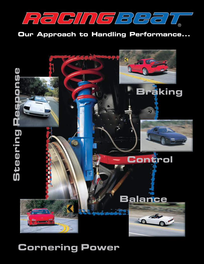
Section
Balance
Cornering Power
St
ee
rin
g R
es
po
ns
e
Braking
Control
Our Approach to Handling Performance...®
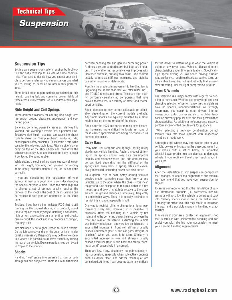
Suspension TipsSetting up a suspension system requires both objec-tive and subjective inputs, as well as some compro-mise. You need to decide how you expect your vehi-cle to perform under varying circumstances and what you’re willing to sacrifice to obtain this perform-ance.
Three broad areas require serious consideration: ride height, handling feel, and cornering power. While all three areas are interrelated, we will address each sepa-rately.
Ride Height and Coil SpringsThree common reasons for altering ride height are: tire and/or ground clearance, appearance, and cor-nering power.
Generally, cornering power increases as ride height is lowered, but lowering a vehicle has a practical limit. Excessive ride height changes can cause the shock rods to strike the “bump rubbers”, producing ride, handling and safety problems. To ascertain if this is the case, try the following technique. Attach a bit of clay or putty on top of the shock body and then drive the vehicle vigorously. Stop and inspect the putty to see if it contacted the bump rubber.
While cutting the coil springs is a cheap way of lower-ing ride height, you may find yourself performing some costly experimentation if the job is not done correctly.
If you are considering the replacement of your springs, it may be a good time to consider changing the shocks on your vehicle. Since the effort required to change a set of springs usually requires the removal of the shocks, the cost of the installation can be reduced if both jobs are undertaken at the same time.
Besides, if you have a high mileage RX-7 that is still running on the original shocks, it is probably about time to replace them anyways! Installing a set of new, high performance spring on a set of tired, old shocks can overwork the shock and may produce a “springy”, “bouncy” ride.
Tire clearance is not a good reason to raise a vehicle. Do the job correctly and alter the outer or inner fender panel, as necessary. Drag racing may be the one excep-tion where it is possible to improve traction by raising the rear of the vehicle. Exercise caution - you don t want to “top out” the shocks.
Shocks Handling “feel” enters into an area that can be both ambiguous and subjective. There is a real distinction
between handling feel and genuine cornering power. At times they are contradictory, but both are impor-tant. In general terms, responsiveness improves with increased stiffness, but only to a point! Ride comfort usually suffers as stiffness increases, and stability can either improve or deteriorate.
Possibly the greatest improvement to handling feel is upgrading the shock absorber. We offer KONI, KYB, and TOKICO shocks and struts. These are high qual-ity, performance-enhancing components that have proven themselves in a variety of street and motor-sport activities.
Shock dampening may be non-adjustable or adjust-able, depending on the current models available. Adjustable shocks are typically adjusted by a small knob either on the top or side of the shock.
Shocks for the 1979 and earlier models have becom-ing increasing more difficult to locate as many of these earlier applications are being discontinued as demand decreases.
Sway BarsSway bars (roll rate) and coil springs (spring rates) also impact vehicle handling. Again, a modest stiffen-ing in the springs and/or sway bars can improve stability and responsiveness, but ride comfort may be sacrificed depending on the stiffness of the springs and sway bars. If spring rates are exces-sively increased, cornering power can also suffer.
As a general rule at best, softly sprung vehicles develop greater cornering power than firmly sprung vehicles, up to the point where the chassis “crashes” the ground. One exception to this rule is that as a tire moves up and down, its attitude relative to the chas-sis and the ground changes dramatically, frequently in undesirable ways. Thus, it is usually desirable to restrict this change, especially in roll.
One way to restrict roll is to change to a higher per-formance sway bar. However, it is possible to adversely affect the handling of a vehicle by not maintaining the cornering power balance between the front and rear of the vehicle. Assuming the vehicle was initially in balance - and very few vehicles are - a substantial increase in front roll stiffness usually causes understeer (that is, the car goes straight, or “pushes”, when you want it to turn). Similarly, a substantial increase in rear roll stiffness usually causes oversteer (that is, the back end starts “com-ing around” excessively in a corner).
There are few, if any, absolutely true points concern-ing suspension, especially when subjective concepts such as driver “feel” and “driver “technique” are considered. At times it can become extremely difficult
for the driver to determine just what the vehicle is doing at any given time. Vehicles display different characteristics under different situations. Specifically, high speed driving vs. low speed driving; smooth road surface vs. rough road surface; banked turns vs. off camber turns. You will undoubtedly find yourself experimenting until the right compromise is found.
Tires & WheelsTire selection is a major factor with regards to han-dling performance. With the extremely large and ever changing selection of performance tires available we have no specific recommendations. We strongly recommend you speak to other drivers, internet newsgroups, autocross racers, etc... to obtain feed-back on currently popular tires and their performance characteristics. As additional reference also speak to performance-oriented tire dealers for guidance.
When selecting a tire/wheel combination, do not tolerate tires that make contact with suspension members or body work.
Although larger wheels may improve the look of your vehicle, beware of increasing the unsprung weight of your vehicle with a set of heavy, but attractive wheels! Lower profile tires can also lead to damaged wheels if you routinely travel over rough roads in your area.
AlignmentAfter the installation of any suspension component that changes or alters the alignment of the vehicle, we recommend that you have your suspension re-aligned.
It can be common to find that the installation of vari-ous aftermarket products (i.e, excessively low coil springs) will not allow the vehicle to be brought back into “factory specifications”. For a car that is used primarily for street use, this may result in increased tire wear and a possible change in handling charac-teristics.
If available in your area, contact an alignment shop that is familiar with performance handling and can assist you with aligning your suspension to meet your specific handling requirements.
68 www.racingbeat.com

Suspension Components
www.racingbeat.com69
1979-85 RX-7 Front and Rear Sway BarsOur Racing Beat-designed sway bars reduce chassis roll in turns and increase the RX-7's sensitivity to steering input, thereby improving maximum corner-ing power. We engineer these components to provide optimal front-to-rear balance utilizing select steel alloys, controlled heat-treating, and specific bar diameter and geometry.
These bars come complete with mounting hardware (including high density urethane mounting bushings and bushing lubricant) and installation instructions. All Racing Beat sway bars utilize the stock sway bar links.
1979-85 RX-7 Front Bar (18-inch O.D.) . . . . . . . .Part No. 14100 1979-85 RX-7 Rear Bar (w-inch O.D.- adjustable) Part No. 14102
1979-85 RX-7 Adjustable Front Lower Control ArmsRX-7 Adjustable Front Lower Control Arms add a new dimension of adjustability to your car. In order to get the most from your RX-7's chassis, you need camber adjustability. This kit also allows you to correct an error in your chassis, or to pre-set incremental nega-tive camber for better handling all the time (we rec-ommend .5° negative camber maximum for continu-ous use).
These arms can be shortened up to 2” from stock (approximately 1.3° more positive camber than stock) or lengthened up to 1s” from stock (approx-imately 4.4° more negative camber than stock). The original rubber inner joint is retained to isolate road shocks and noise.
When front wheel negative camber is increased with this kit, there is a possibility that the front tire may contact the fender under some combination of bump and turn. This is especially true if wider-than stock wheels and tires are fitted. It is the user's responsibil-ity to determine that there is adequate clearance for his application.
1979-85 RX-7 . . . . . . . . . . . . . . . Part No. 14006
1979-85 RX-7 Front Sway Bar
1979-85 RX-7 Fully Adjustable Rear Bar
1979-85 RX-7 Replacement End Link Kit For Racing Beat Rear Sway BarThis replacement sway bar end link kit is specially designed to replace the original components supplied in the Racing Beat rear sway bar (PN 14102 at left). This kit is supplied with end link bushings specifically intended for use with the Racing Beat Sway Bar, these are not indented for use a replacements for a set of stock links or for use on a stock sway bar. For an OE replacement option, see the chart on page 71.
Replacement End Links for Racing Beat Sway Bar ........................................... Part No. 14202

1986-92 RX-7 Rear Suspension Camber AdjusterThe Rear Suspension Camber Adjuster is an adjust-able link that replaces the stock, fixed-length link to allow moderate rear camber changes by “tilting” the rear suspension subframe. The immediate range of adjustment is .60 degrees less negative camber to .77 degrees more negative camber. With careful inspection and possibly some minor dimpling of the floor pan, this range can be nearly doubled. After installation, adjustments to camber are quickly made. There is virtually no “toe” change with this adjust-ment.
1986-1992 RX-7 (All) . . . . . . . . . Part No. 14008 (One required per chassis)
1986-92 RX-7 Adjustable Heavy Duty Sway Bar EndlinksThese sway bar links interchange exactly with the stock links. Heat-treated and anodized aluminum end housing, fitted with urethane bushings, reduce the amount of flexing present in the stock rubber-bushing links and avoid the noise and vibration transmitted by “Rod End” links. For drivers who are very sensitive to chassis set up, these links permit setting each sway bar to a “neutral position” with the chassis at ride height to avoid “preloading” the bar. Each set contains two (2) links - enough for one (1) sway bar.
1986-1992 RX-7 (Pair) . . . . . . . . . Part No. 14200
1986-92 RX-7 Rear Suspension Upright Toe EliminatorOn the 1986-92 RX-7s Mazda introduced the Dynamic Tuned Suspension System (DTSS). DTSS allows each wheel to “steer” by itself based on how many “G”s of cornering force the outside wheel is generat-ing. In stock form, cornering forces operating on the rear upright cause up to approximately 1 degree of toe-in on the outside wheel in a turn. This character-istic tends to compensate for driver input or road variations that might cause a vehicle to go out of control. However, this same characteristic also inter-feres with the feedback that a sensitive driver needs to operate his car near the limit of adhesion and generally reduces the ultimate cornering force.
Our Toe Eliminator - a rigid joint that replaces the stock rubber joint - provides a perceptible improve-ment in feedback to the driver. There is no longer a need to modulate inputs based on the constantly fluctuating elastic joint output.
The kit consists of two (2) rigid plastic sleeves and two (2) steel bushings which should be installed with the aid of a hydraulic press or a large vise. No re-alignment is necessary after installation.
1986-92 RX-7 (All) . . . . . . . . . . Part No. 14050
1986-92 RX-7 Front Suspension Lowering KitThe Front Suspension Lowering Kit utilizes Racing Beat-modified top strut mounts to lower the front of the 1986-92 RX-7 approximately w”, without adversely affecting wheel travel or ride comfort.
The kit is a bolt-on design that does not require any cutting of the strut towers and may be used with our High Performance Front Coil Springs to further lower ride height.The kit fits all 1986-92 RX-7’s, except those equipped with the factory Auto Adjust suspensions.
1986-92 RX-7 . . . . . . . . . . . . . . Part No. 14000
Front Suspension Racing MountsWe offer the Mazda Factory Race competition mounts (40% stiffer than the stock units) for racing applications. Two (2) required per car. Also available, Racing Beat can modify these race mounts to lower the front approximately w”.
1986-92 RX-7 (Shown) . . . . . . . . . Part No. 14012
1986-92 RX-7 (includes lowering) . Part No. 14013
Suspension Components
70
1986-92 RX-7 Endlinks
1986-92 RX-7 Front Suspension Lowering Kit
www.racingbeat.com
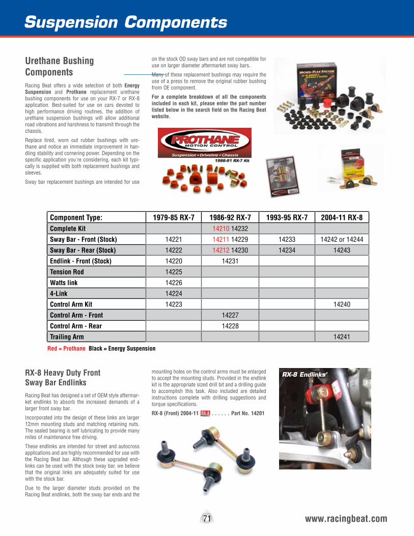
www.racingbeat.com71
RX-8 Heavy Duty Front Sway Bar EndlinksRacing Beat has designed a set of OEM style aftermar-ket endlinks to absorb the increased demands of a larger front sway bar.
Incorporated into the design of these links are larger 12mm mounting studs and matching retaining nuts. The sealed bearing is self lubricating to provide many miles of maintenance free driving.
These endlinks are intended for street and autocross applications and are highly recommended for use with the Racing Beat bar. Although these upgraded end-links can be used with the stock sway bar, we believe that the original links are adequately suited for use with the stock bar.
Due to the larger diameter studs provided on the Racing Beat endlinks, both the sway bar ends and the
mounting holes on the control arms must be enlarged to accept the mounting studs. Provided in the endlink kit is the appropriate sized drill bit and a drilling guide to accomplish this task. Also included are detailed instructions complete with drilling suggestions and torque specifications.
RX-8 (Front) 2004-11 . . . . . . Part No. 14201
Suspension Components
RX-8 Endlinks
RX-8PRODUCT
Urethane Bushing ComponentsRacing Beat offers a wide selection of both Energy Suspension and Prothane replacement urethane bushing components for use on your RX-7 or RX-8 application. Best-suited for use on cars devoted to high performance driving routines, the addition of urethane suspension bushings will allow additional road vibrations and harshness to transmit through the chassis.
Replace tired, worn out rubber bushings with ure-thane and notice an immediate improvement in han-dling stability and cornering power. Depending on the specific application you're considering, each kit typi-cally is supplied with both replacement bushings and sleeves.
Sway bar replacement bushings are intended for use
on the stock OD sway bars and are not compatible for use on larger diameter aftermarket sway bars.
Many of these replacement bushings may require the use of a press to remove the original rubber bushing from OE component.
For a complete breakdown of all the components included in each kit, please enter the part number listed below in the search field on the Racing Beat website.
Component Type: 1979-85 RX-7 1986-92 RX-7 1993-95 RX-7 2004-11 RX-8Complete Kit 14210 14232
Sway Bar - Front (Stock) 14221 14211 14229 14233 14242 or 14244
Sway Bar - Rear (Stock) 14222 14212 14230 14234 14243
Endlink - Front (Stock) 14220 14231
Tension Rod 14225
Watts link 14226
4-Link 14224
Control Arm Kit 14223 14240
Control Arm - Front 14227
Control Arm - Rear 14228
Trailing Arm 14241
Red = Prothane Black = Energy Suspension
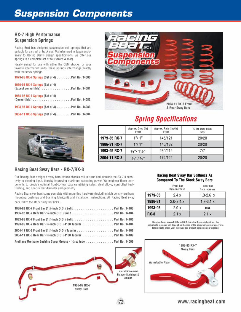
Suspension Components
www.racingbeat.com
RX-7 High Performance Suspension SpringsRacing Beat has designed suspension coil springs that are suitable for a street or track use. Manufactured in Japan exclu-sively to Racing Beat's design specifications, we offer our springs in a complete set of four (front & rear).
Ideally suited for use with either the OEM shocks, or your favorite aftermarket units, these springs interchange exactly with the stock springs.
1979-85 RX-7 Springs (Set of 4) . . . . . . . .Part No. 14080
1986-91 RX-7 Springs (Set of 4) (Except convertible) . . . . . . . . . . . . . . . .Part No. 14081
1988-92 RX-7 Springs (Set of 4) (Convertible) . . . . . . . . . . . . . . . . . . . . .Part No. 14082
1993-95 RX-7 Springs (Set of 4) . . . . . . . .Part No. 14083
2004-11 RX-8 Springs (Set of 4) . . . . . . . .Part No. 14084
Spring Specifications
Racing Beat Sway Bars - RX-7/RX-8Our Racing Beat-designed sway bars reduce chassis roll in turns and increase the RX-7's sensi-tivity to steering input, thereby improving maximum cornering power. We engineer these com-ponents to provide optimal front-to-rear balance utilizing select steel alloys, controlled heat-treating, and specific bar diameter and geometry.
Racing Beat sway bars come complete with mounting hardware (including high density urethane mounting bushings and bushing lubricant) and installation instructions. All Racing Beat sway bars utilize the stock sway bar links.
1986-92 RX-7 Front Bar (18-inch O.D.) Solid . . . . . . . . . . . . . . . . . . . . . . Part No. 14103 1986-92 RX-7 Rear Bar (s-inch O.D.) Solid . . . . . . . . . . . . . . . . . . . . . . . Part No. 14104
1993-95 RX-7 Front Bar (14-inch O.D.) Solid . . . . . . . . . . . . . . . . . . . . . . Part No. 14103 1993-95 RX-7 Rear Bar (w-inch O.D.) 4130 Tubular . . . . . . . . . . . . . . . . . Part No. 14104
2004-11 RX-8 Front Bar (14-inch O.D.) Tubular . . . . . . . . . . . . . . . . . . . . Part No. 14108 2004-11 RX-8 Rear Bar (w-inch O.D.) 4130 Tubular . . . . . . . . . . . . . . . . . Part No. 14109
Prothane Urethane Bushing Super Grease - 2 oz tube . . . . . . . . . . . . . . . Part No. 14099
1986-92 RX-7 Sway Bars
Front Bar Rate Increase
Mazda offered several different O.D. bars for these applications, the actual rate increase will depend on the size of the stock bar on your car. For a
detailed rate chart, visit the sway bar product listings on our website.
Rear Bar Rate Increase
Racing Beat Sway Bar Stiffness As Compared To The Stock Sway Bars
2004-11 RX-8 Front & Rear Sway Bars
Lateral MovementStopper Bushings &
Clamps
1993-95 RX-7Sway Bars
Adjustable Rear
Approx. Drop (in)Fr/Rr
Approx. Rate (lbs/in)Fr/Rr
% Inc Over StockFr/Rr
1979-85 RX-7 1”/ 1” 145/121 20/20
1986-91 RX-7 1”/ 1” 145/132 20/20
1993-95 RX-7 w”/ 12” 260/212 7/7
2004-11 RX-8 2” / 2” 174/122 20/20
1979-85 2.4 x 1.3-2.6 x
1986-91 2.0-2.4 x 1.7-3.1 x
1993-95 2.0 x n/a
RX-8 2.1 x 2.1 x
72
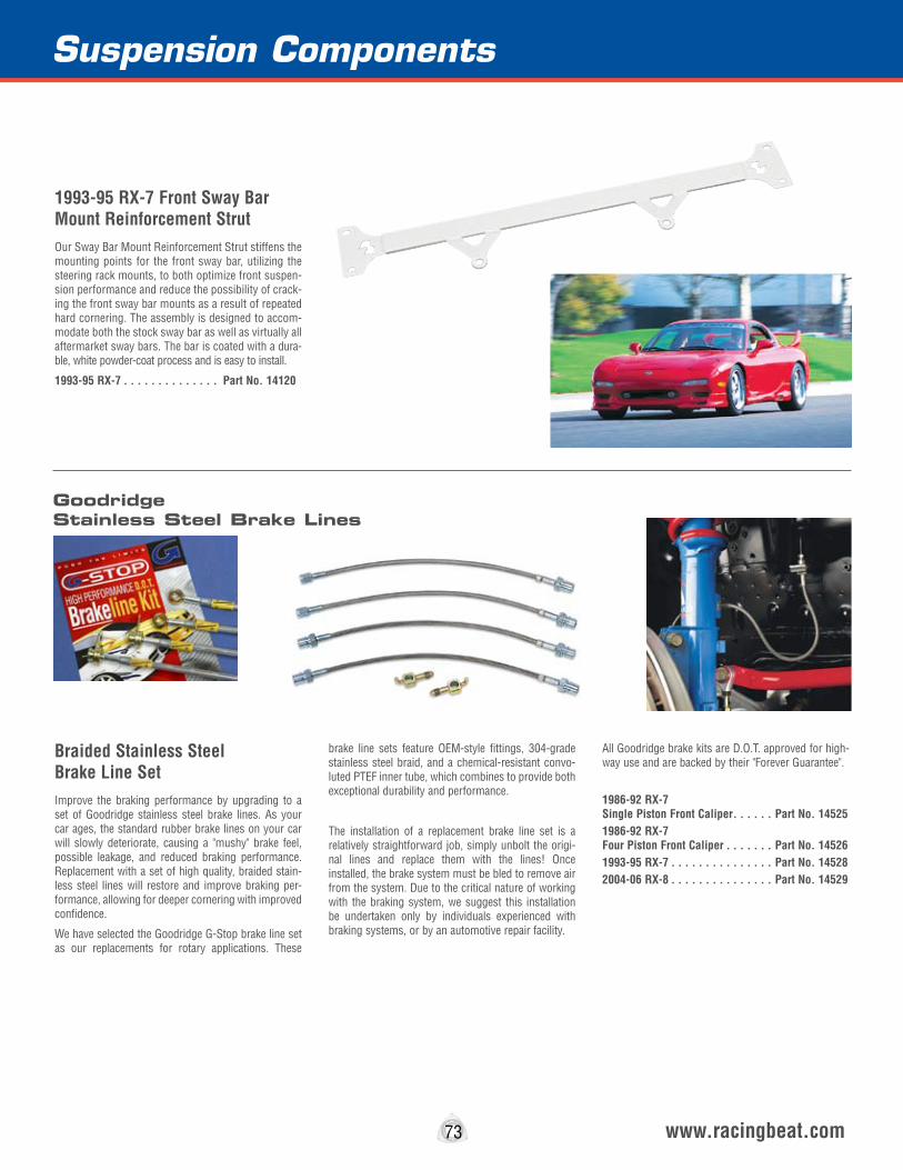
73 www.racingbeat.com
1993-95 RX-7 Front Sway Bar Mount Reinforcement StrutOur Sway Bar Mount Reinforcement Strut stiffens the mounting points for the front sway bar, utilizing the steering rack mounts, to both optimize front suspen-sion performance and reduce the possibility of crack-ing the front sway bar mounts as a result of repeated hard cornering. The assembly is designed to accom-modate both the stock sway bar as well as virtually all aftermarket sway bars. The bar is coated with a dura-ble, white powder-coat process and is easy to install.
1993-95 RX-7 . . . . . . . . . . . . . . Part No. 14120
Braided Stainless Steel Brake Line SetImprove the braking performance by upgrading to a set of Goodridge stainless steel brake lines. As your car ages, the standard rubber brake lines on your car will slowly deteriorate, causing a "mushy" brake feel, possible leakage, and reduced braking performance. Replacement with a set of high quality, braided stain-less steel lines will restore and improve braking per-formance, allowing for deeper cornering with improved confidence.
We have selected the Goodridge G-Stop brake line set as our replacements for rotary applications. These
brake line sets feature OEM-style fittings, 304-grade stainless steel braid, and a chemical-resistant convo-luted PTEF inner tube, which combines to provide both exceptional durability and performance.
The installation of a replacement brake line set is a relatively straightforward job, simply unbolt the origi-nal lines and replace them with the lines! Once installed, the brake system must be bled to remove air from the system. Due to the critical nature of working with the braking system, we suggest this installation be undertaken only by individuals experienced with braking systems, or by an automotive repair facility.
All Goodridge brake kits are D.O.T. approved for high-way use and are backed by their "Forever Guarantee".
1986-92 RX-7 Single Piston Front Caliper . . . . . . Part No. 145251986-92 RX-7 Four Piston Front Caliper . . . . . . . Part No. 145261993-95 RX-7 . . . . . . . . . . . . . . . Part No. 145282004-06 RX-8 . . . . . . . . . . . . . . . Part No. 14529
Suspension Components
GoodridgeStainless Steel Brake Lines

Suspension Components
74 www.racingbeat.com
KONI® Shock AbsorbersKONI has a long-standing reputation in racing circles as a manufacturer of high performance, top quality shocks and struts. KONI uses superior materials in the manufacture of their components to ensure sig-nificantly improved handling and excellent durability. Backed by KONI’s Limited Lifetime Warranty.
1981-85 RX-7
1981-85 Front . . . . . . . . . . . . . . Part No. 14326
1986-92 RX-7 . . . . . . . . . . . . . Discontinued
1993-95 RX-7 (Externally Adjustable) Features adjustable 3-position spring seat -vehicle can be lowered up to 10mm Front, 15mm Rear.
Front Right . . . . . . . . . . . . . . . . Part No. 14360 Front Left . . . . . . . . . . . . . . . . . Part No. 14361 Rear. . . . . . . . . . . . . . . . . . . . . Part No. 14365
2004-2006 RX-8 The KONI front units are externally adjustable, the rear units are not.
Front (Adjustable) . . . . . . . . . . . . . Part No. 14366 Rear (2004-08) . . . . . . . . . . . . . Part No. 14367
TOKICO® Shock AbsorbersTOKICO is one of the world’s largest manufacturers of shock absorbers for both original equipment and high performance applications. TOKICO offers the D-SPEC or ILLUMINA externally adjustable struts and shocks, and the STANDARD SERIES (HP) struts and shocks (non-adjustable). Backed by Tokico’s Limited Lifetime Warranty.
1981-85 RX-7 Standard (HP) Strut Assembly 1981-85 Front . . . . . . . . . . . . . . . Part No. 14401 1979-85 Rear . . . . . . . . . . . . . . . Part No. 14450
Illumina Strut Assembly (Adjustable) 1981-85 Front . . . . . . . . . . . . . . Part No. 14425 1979-85 Rear . . . . . . . . . . . . . . . Part No. 14475
1986-92 RX-7 Standard (HP) Strut Assembly (All models) Front Right* . . . . . . . . . . . . . . . . Part No. 14403 Front Left* . . . . . . . . . . . . . . . . Part No. 14404 Rear . . . . . . . . . . . . . . . . . . . . . Part No. 14451
Illumina Strut Assembly (Adjustable - All models) Front Right* . . . . . . . . . . . . . . . Part No. 14420 Front Left* . . . . . . . . . . . . . . . . Part No. 14421 Rear . . . . . . . . . . . . . . . . . . . . . Part No. 14470
1993-95 RX-7 Illumina Strut Assembly (Adjustable) Front Right . . . . . . . . . . . . . . . . Part No. 14480 Front Left . . . . . . . . . . . . . . . . . . Part No. 14481 Rear . . . . . . . . . . . . . . . . . . . . . Part No. 14482
2004-2011 RX-8 D-Spec ShocksThe Tokico D-Spec Shocks are fully adjustable (front & rear) shocks for the RX-8 application. The use of extension cable adjusters are required to allow remote access to the top of the rear shocks for adjustments.
Complete Shock Set . . . . . . . . . . Part No. N/A
Extension Cable Adjusters (Pair) . . Part No. 14369
KYB® Shock AbsorbersThe KYB AGX allows the driver to adjust damping to match specific driving conditions quickly and easily. Damping rate is selected by inserting a small screw-driver into the slot on the top of the piston rod (front), or by rotating an adjustment knob on the side of the shock body (rear). Backed by KYB’s Limited 12-Month Warranty.
1986-92 RX-7 AGX Strut Assembly (Externally Adjustable)
Front Right . . . . . . . . . . . . . . . . Part No. 14541 Front Left . . . . . . . . . . . . . . . . . Part No. 14542 Rear . . . . . . . . . . . . . . . . . . . . Part No. 14544Note: Installation of these struts/shocks disables the optional Electronic Suspension Control if your vehicle is so equipped.
KYB's GR-2 & Excel-G shocks are an excellent after-market replacement for those looking for a compliant and comfortable ride in their RX-7. These nonadjusta-ble shocks are a direct replacement for the stock shocks.
1979-85 RX-7 1979-80 Front GR-2 . . . . . . . . . . Part No. 14319 1981-85 12A Front GR-2 . . . . . . . Part No. 14320 1981-85 12A Rear Excel-G . . . . . Part No. 14321
1986-92 Front Left GR-2 . . . . . . . Part No. 14323 1986-92 Front Right GR-2 . . . . . . Part No. 14324 1986-92 Front Rear Gas-A-Just . . Part No. 14325
*Note: Installation of these struts/shocks disables the optional Electronic Suspension Control if your vehicle is so equipped.
Springs not included.
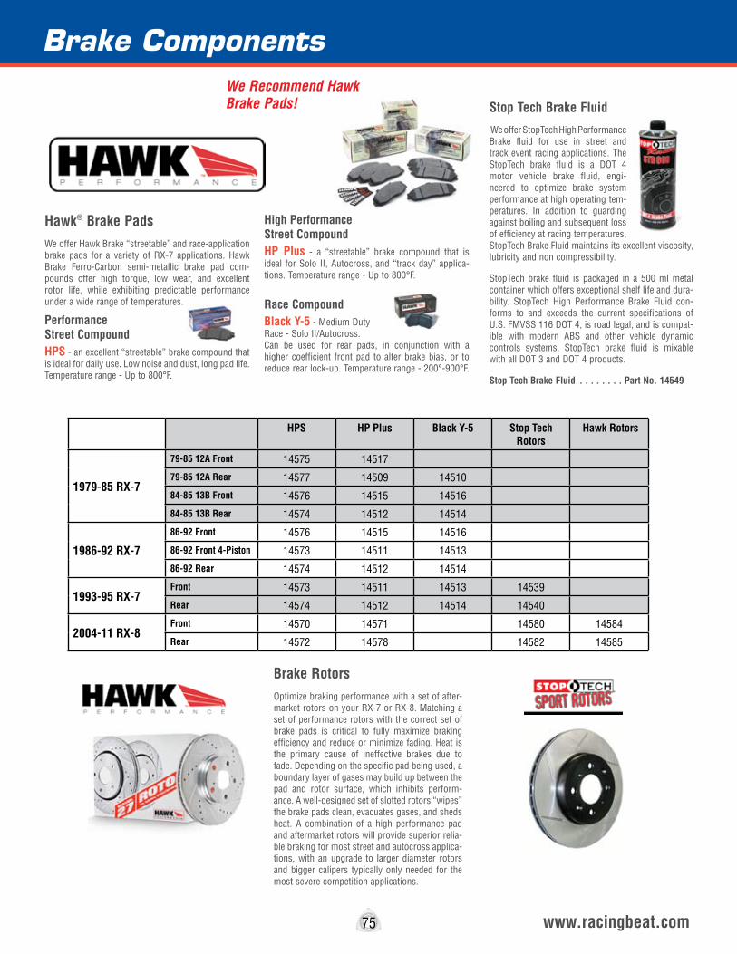
Brake Components
www.racingbeat.com75
Hawk® Brake PadsWe offer Hawk Brake “streetable” and race-application brake pads for a variety of RX-7 applications. Hawk Brake Ferro-Carbon semi-metallic brake pad com-pounds offer high torque, low wear, and excellent rotor life, while exhibiting predictable performance under a wide range of temperatures.
Performance Street CompoundHPS - an excellent “streetable” brake compound that is ideal for daily use. Low noise and dust, long pad life. Temperature range - Up to 800°F.
High Performance Street CompoundHP Plus - a “streetable” brake compound that is ideal for Solo II, Autocross, and “track day” applica-tions. Temperature range - Up to 800°F.
Race Compound Black Y-5 - Medium Duty Race - Solo II/Autocross.Can be used for rear pads, in conjunction with a higher coefficient front pad to alter brake bias, or to reduce rear lock-up. Temperature range - 200°-900°F.
Brake RotorsOptimize braking performance with a set of after-market rotors on your RX-7 or RX-8. Matching a set of performance rotors with the correct set of brake pads is critical to fully maximize braking efficiency and reduce or minimize fading. Heat is the primary cause of ineffective brakes due to fade. Depending on the specific pad being used, a boundary layer of gases may build up between the pad and rotor surface, which inhibits perform-ance. A well-designed set of slotted rotors “wipes” the brake pads clean, evacuates gases, and sheds heat. A combination of a high performance pad and aftermarket rotors will provide superior relia-ble braking for most street and autocross applica-tions, with an upgrade to larger diameter rotors and bigger calipers typically only needed for the most severe competition applications.
Stop Tech Brake Fluid
We offer StopTech High Performance Brake fluid for use in street and track event racing applications. The StopTech brake fluid is a DOT 4 motor vehicle brake fluid, engi-neered to optimize brake system performance at high operating tem-peratures. In addition to guarding against boiling and subsequent loss of efficiency at racing temperatures, StopTech Brake Fluid maintains its excellent viscosity, lubricity and non compressibility.
StopTech brake fluid is packaged in a 500 ml metal container which offers exceptional shelf life and dura-bility. StopTech High Performance Brake Fluid con-forms to and exceeds the current specifications of U.S. FMVSS 116 DOT 4, is road legal, and is compat-ible with modern ABS and other vehicle dynamic controls systems. StopTech brake fluid is mixable with all DOT 3 and DOT 4 products.
Stop Tech Brake Fluid . . . . . . . . Part No. 14549
We Recommend Hawk Brake Pads!
HPS HP Plus Black Y-5 Stop Tech Rotors
Hawk Rotors
1979-85 RX-7
79-85 12A Front 14575 14517
79-85 12A Rear 14577 14509 14510
84-85 13B Front 14576 14515 14516
84-85 13B Rear 14574 14512 14514
1986-92 RX-7
86-92 Front 14576 14515 14516
86-92 Front 4-Piston 14573 14511 14513
86-92 Rear 14574 14512 14514
1993-95 RX-7Front 14573 14511 14513 14539
Rear 14574 14512 14514 14540
2004-11 RX-8Front 14570 14571 14580 14584
Rear 14572 14578 14582 14585
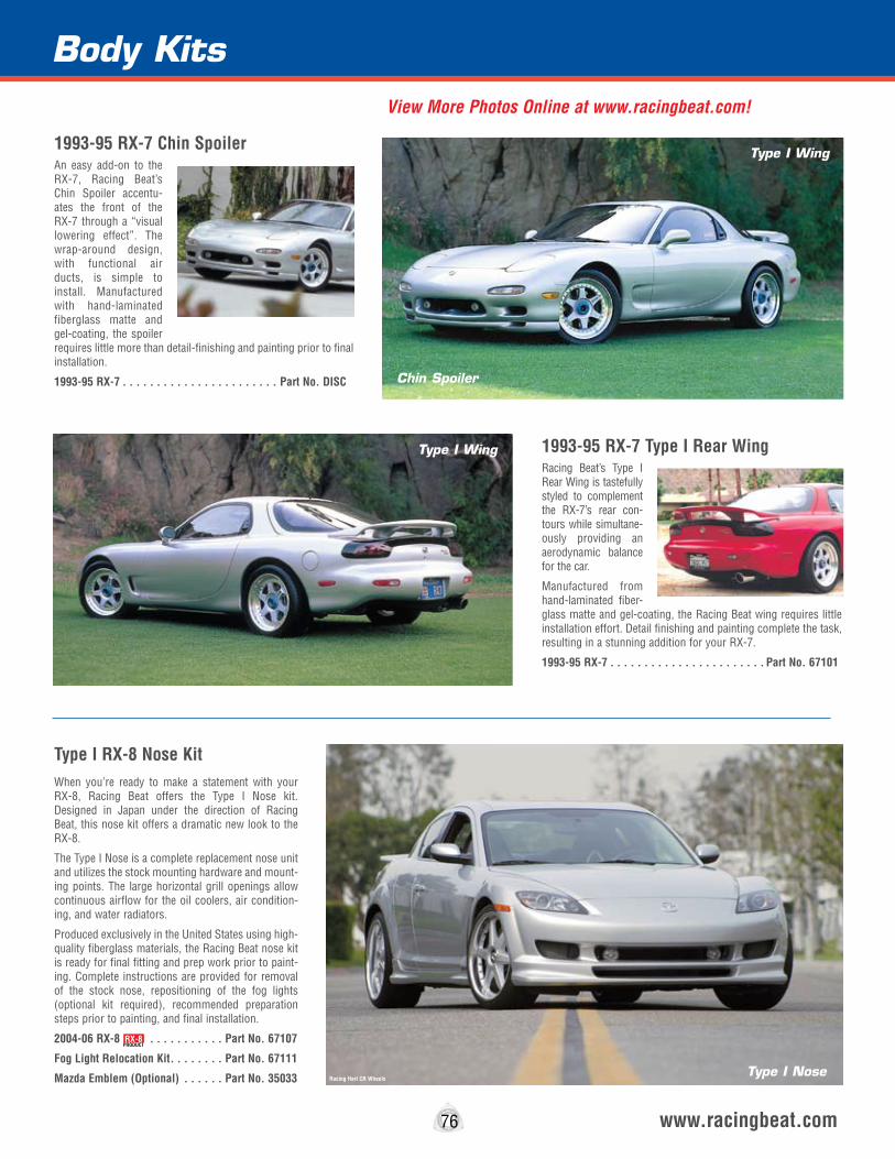
1993-95 RX-7 Chin SpoilerAn easy add-on to the RX-7, Racing Beat’s Chin Spoiler accentu-ates the front of the RX-7 through a “visual lowering effect”. The wrap-around design, with functional air ducts, is simple to install. Manufactured with hand-laminated fiberglass matte and gel-coating, the spoiler requires little more than detail-finishing and painting prior to final installation.
1993-95 RX-7 . . . . . . . . . . . . . . . . . . . . . . . Part No. DISC
Body Kits
76 www.racingbeat.com
1993-95 RX-7 Type I Rear WingRacing Beat’s Type I Rear Wing is tastefully styled to complement the RX-7’s rear con-tours while simultane-ously providing an aerodynamic balance for the car.
Manufactured from hand-laminated fiber-glass matte and gel-coating, the Racing Beat wing requires little installation effort. Detail finishing and painting complete the task, resulting in a stunning addition for your RX-7.
1993-95 RX-7 . . . . . . . . . . . . . . . . . . . . . . . Part No. 67101
Type I RX-8 Nose KitWhen you’re ready to make a statement with your RX-8, Racing Beat offers the Type I Nose kit. Designed in Japan under the direction of Racing Beat, this nose kit offers a dramatic new look to the RX-8.
The Type I Nose is a complete replacement nose unit and utilizes the stock mounting hardware and mount-ing points. The large horizontal grill openings allow continuous airflow for the oil coolers, air condition-ing, and water radiators.
Produced exclusively in the United States using high-quality fiberglass materials, the Racing Beat nose kit is ready for final fitting and prep work prior to paint-ing. Complete instructions are provided for removal of the stock nose, repositioning of the fog lights (optional kit required), recommended preparation steps prior to painting, and final installation.
2004-06 RX-8 . . . . . . . . . . . Part No. 67107
Fog Light Relocation Kit . . . . . . . . Part No. 67111
Mazda Emblem (Optional) . . . . . . Part No. 35033 Type I Nose
Type I Wing
Type I Wing
Chin Spoiler
Racing Hart CR Wheels
RX-8PRODUCT
View More Photos Online at www.racingbeat.com!
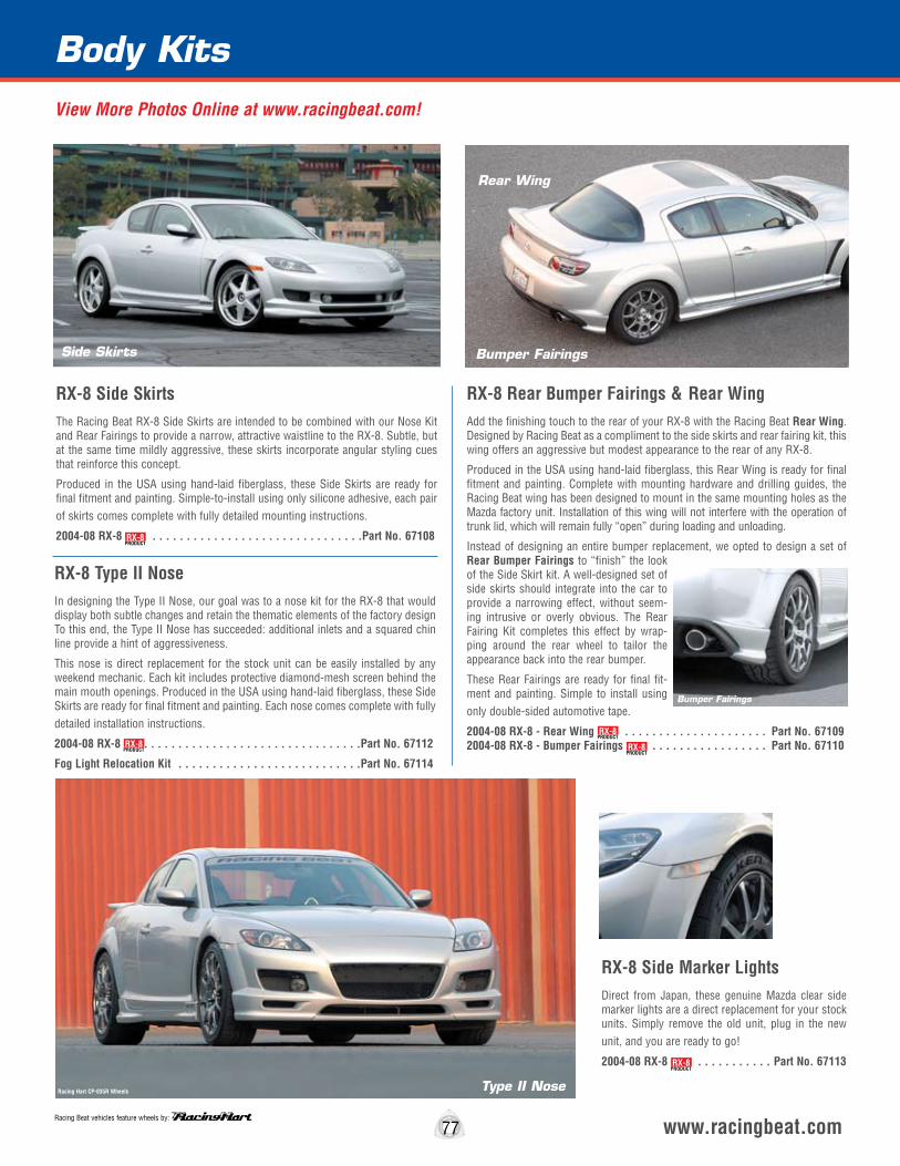
77 www.racingbeat.com
RX-8 Side SkirtsThe Racing Beat RX-8 Side Skirts are intended to be combined with our Nose Kit and Rear Fairings to provide a narrow, attractive waistline to the RX-8. Subtle, but at the same time mildly aggressive, these skirts incorporate angular styling cues that reinforce this concept.
Produced in the USA using hand-laid fiberglass, these Side Skirts are ready for final fitment and painting. Simple-to-install using only silicone adhesive, each pair of skirts comes complete with fully detailed mounting instructions.
2004-08 RX-8 . . . . . . . . . . . . . . . . . . . . . . . . . . . . . . .Part No. 67108
RX-8 Side Marker LightsDirect from Japan, these genuine Mazda clear side marker lights are a direct replacement for your stock units. Simply remove the old unit, plug in the new unit, and you are ready to go!
2004-08 RX-8 . . . . . . . . . . . Part No. 67113
RX-8 Type II NoseIn designing the Type II Nose, our goal was to a nose kit for the RX-8 that would display both subtle changes and retain the thematic elements of the factory design To this end, the Type II Nose has succeeded: additional inlets and a squared chin line provide a hint of aggressiveness.
This nose is direct replacement for the stock unit can be easily installed by any weekend mechanic. Each kit includes protective diamond-mesh screen behind the main mouth openings. Produced in the USA using hand-laid fiberglass, these Side Skirts are ready for final fitment and painting. Each nose comes complete with fully detailed installation instructions.
2004-08 RX-8 . . . . . . . . . . . . . . . . . . . . . . . . . . . . . . . .Part No. 67112
Fog Light Relocation Kit . . . . . . . . . . . . . . . . . . . . . . . . . . .Part No. 67114
RX-8 Rear Bumper Fairings & Rear WingAdd the finishing touch to the rear of your RX-8 with the Racing Beat Rear Wing. Designed by Racing Beat as a compliment to the side skirts and rear fairing kit, this wing offers an aggressive but modest appearance to the rear of any RX-8.
Produced in the USA using hand-laid fiberglass, this Rear Wing is ready for final fitment and painting. Complete with mounting hardware and drilling guides, the Racing Beat wing has been designed to mount in the same mounting holes as the Mazda factory unit. Installation of this wing will not interfere with the operation of trunk lid, which will remain fully “open” during loading and unloading.
Instead of designing an entire bumper replacement, we opted to design a set of Rear Bumper Fairings to “finish” the look of the Side Skirt kit. A well-designed set of side skirts should integrate into the car to provide a narrowing effect, without seem-ing intrusive or overly obvious. The Rear Fairing Kit completes this effect by wrap-ping around the rear wheel to tailor the appearance back into the rear bumper.
These Rear Fairings are ready for final fit-ment and painting. Simple to install using only double-sided automotive tape.
2004-08 RX-8 - Rear Wing . . . . . . . . . . . . . . . . . . . . . Part No. 67109 2004-08 RX-8 - Bumper Fairings . . . . . . . . . . . . . . . . . Part No. 67110
Body Kits
Side Skirts
Type II Nose
Rear Wing
Bumper Fairings
Bumper Fairings
Racing Beat vehicles feature wheels by:
Racing Hart CP-035R Wheels
RX-8PRODUCT
RX-8PRODUCT
RX-8PRODUCT
RX-8PRODUCT
RX-8PRODUCT
View More Photos Online at www.racingbeat.com!

Apparel & Accessories
78 www.racingbeat.com
1995 Bonneville Land Speed Record T-ShirtThis classic T-shirt commemorates Racing Beat’s third Bonneville Land Speed Record. This shirt illustrates the RX-7 as it appeared after its record setting run of over 242 MPH across the salt flats.
This shirt is screened in eight vibrant colors on a high quality 100% cotton shirt with the Racing Beat logo featured on the front.
Large . . . . . . . . . . . . . . . . . . . . . . . . . . . . . . DISCONTINUED
X-Large . . . . . . . . . . . . . . . . . . . . . . . . . . . . DISCONTINUED
XX-Large . . . . . . . . . . . . . . . . . . . . . . . . . . . DISCONTINUED
Logo CapBlack - (Adjustable) . . . . . . . Part No. 21030
Racing Beat MotorsportsT-ShirtThis popular Racing Beat motorsports team shirt is the perfect fit for any easy-going occasion. Our Racing Beat team shirt is screened in three colors on a high quality 100% cotton shirt with the Racing Beat logo fea-tured on the front .
Medium . . . . . . . . . . . . . . . . . . . . . . . . . . . . . . . . . . . . 21209M
Large . . . . . . . . . . . . . . . . . . . . . . . . . . . . . . . . . . . . . . 21209L
X-Large . . . . . . . . . . . . . . . . . . . . . . . . . . . . . . . . . . . . 21209XL
XX-Large . . . . . . . . . . . . . . . . . . . . . . . . . . . . . . . . . . . 21209XXL
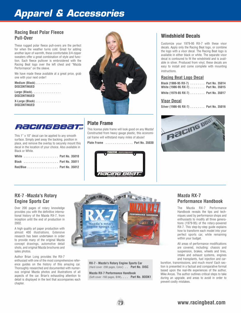
79 www.racingbeat.com
Windshield DecalsCustomize your 1979-95 RX-7 with these visor decals. Apply only the Racing Beat logo, or combine the logo with a visor decal. The Racing Beat logo is available in either black or white. The separate visor decal is contoured to fit the windshield and is avail-able in silver. Produced from vinyl, these decals are easy to install and come complete with mounting instructions.
Racing Beat Logo DecalBlack (1986-95 RX-7) . . . . . . . . Part No. 35014 White (1986-95 RX-7) . . . . . . . . Part No. 35015
White (1979-85 RX-7) . . . . . . . . Part No. 35017
Visor DecalSilver (1986-95 RX-7) . . . . . . . . Part No. 35016
This 1” x 10” decal can be applied to any smooth surface. Simply peel away the backing, position in place, and remove the overlay to securely mount this decal in the location of your choice. Also available in Black or White.
White . . . . . . . . . . . . . . . . . . . Part No. 35010
Black . . . . . . . . . . . . . . . . . . . Part No. 35011
Red/Blue . . . . . . . . . . . . . . . . . Part No. 35012
Plate FrameThis license plate frame will look good on any Mazda! Constructed from heavy gauge plastic, this economi-cal frame will withstand many miles of abuse!
Plate Frame . . . . . . . . . . . . . . . Part No. 35030
Apparel & Accessories
RX-7 -Mazda's Rotary Engine Sports CarOver 200 pages of rotary knowledge provides you with the definitive interna-tional history of the Mazda RX-7, from inception until the end of production in 2002.
A high quality art paper production with almost 400 illustrations. Extensive research has been undertaken in order to provide many of the original Mazda concept drawings, automotive detail shots, and original Mazda brochures and sales photos.
Author Brian Long provides the RX-7 enthusiast with one of the most comprehensive refer-ence guides on the history of this amazing car. Thoroughly researched and documented with numer-ous original Mazda photos and illustrations of all aspects of the car. Brian’s exhausting attention to detail is displayed in the text that accompanies each chapter.
Mazda RX-7 Performance HandbookThe Mazda RX-7 Performance Handbook reveals the tips and tech-niques used by performance shops and enthusiasts to modify all three genera-tions (1979-95) of the rotary-powered RX-7. This step-by-step guide explains how to transform each model into your perfect sports car, while remaining within your budget.
All areas of performance modifications are covered, including: chassis and suspension, brakes, wheels and tires, intake and exhaust systems, engines and transplants, fuel injection and car-
buretion, transmissions, and much more! Each sec-tion is presented in a factual and comparative format based upon the real-life experiences of the author, Mike Ancas. The author outlines critical steps to take during an upgrade, and areas to avoid in order to prevent costly mistakes.
RX-7 - Mazda's Rotary Engine Sports Car (Hard cover -208 pages, Color) . . Part No. DISC
Mazda RX-7 Performance Handbook (Soft cover -160 pages, B/W). . . . Part No. BOOK1
Racing Beat Polar Fleece Pull-OverThese rugged polar fleece pull-overs are the perfect for when the weather turns cold. Great for adding another layer of warmth, these comfortable 3/4-zipper sweaters offer a great combination of style and func-tion. Each fleece pullover is embroidered with the Racing Beat logo over the left chest and “Mazda Performance” on the sleeve.
We have made these available at a great price, grab one with your next order!
Medium (Black) . . . . . . . . . . . . . . DISCONTINUED
Large (Black). . . . . . . . . . . . . . . . DISCONTINUED
X-Large (Black) . . . . . . . . . . . . . . DISCONTINUED
The Heart Of Rotary Performance For Over 40 Years
2016 Edition4789 E Wesley Drive, Anaheim, CA 92807(714) 779-8677 • Fax (714) 779-2902www.racingbeat.com