20158i fire protection
DESCRIPTION
Fire ProtectionTRANSCRIPT

PETRONAS TECHNICAL STANDARDS DESIGN AND ENGINEERING PRACTICE
MANUAL
INSTALLATIONS AND DEPOTS
PART 9 - FIRE PROTECTION
PTS 20.158I
JUNE 1993

PREFACE
PETRONAS Technical Standards (PTS) publications reflect the views, at the time of publication,of PETRONAS OPUs/Divisions.
They are based on the experience acquired during the involvement with the design, construction,operation and maintenance of processing units and facilities. Where appropriate they are basedon, or reference is made to, national and international standards and codes of practice.
The objective is to set the recommended standard for good technical practice to be applied byPETRONAS' OPUs in oil and gas production facilities, refineries, gas processing plants, chemicalplants, marketing facilities or any other such facility, and thereby to achieve maximum technicaland economic benefit from standardisation.
The information set forth in these publications is provided to users for their consideration anddecision to implement. This is of particular importance where PTS may not cover everyrequirement or diversity of condition at each locality. The system of PTS is expected to besufficiently flexible to allow individual operating units to adapt the information set forth in PTS totheir own environment and requirements.
When Contractors or Manufacturers/Suppliers use PTS they shall be solely responsible for thequality of work and the attainment of the required design and engineering standards. Inparticular, for those requirements not specifically covered, the Principal will expect them to followthose design and engineering practices which will achieve the same level of integrity as reflectedin the PTS. If in doubt, the Contractor or Manufacturer/Supplier shall, without detracting from hisown responsibility, consult the Principal or its technical advisor.
The right to use PTS rests with three categories of users :
1) PETRONAS and its affiliates.2) Other parties who are authorised to use PTS subject to appropriate contractual
arrangements.3) Contractors/subcontractors and Manufacturers/Suppliers under a contract with
users referred to under 1) and 2) which requires that tenders for projects,materials supplied or - generally - work performed on behalf of the said userscomply with the relevant standards.
Subject to any particular terms and conditions as may be set forth in specific agreements withusers, PETRONAS disclaims any liability of whatsoever nature for any damage (including injuryor death) suffered by any company or person whomsoever as a result of or in connection with theuse, application or implementation of any PTS, combination of PTS or any part thereof. Thebenefit of this disclaimer shall inure in all respects to PETRONAS and/or any company affiliatedto PETRONAS that may issue PTS or require the use of PTS.
Without prejudice to any specific terms in respect of confidentiality under relevant contractualarrangements, PTS shall not, without the prior written consent of PETRONAS, be disclosed byusers to any company or person whomsoever and the PTS shall be used exclusively for thepurpose they have been provided to the user. They shall be returned after use, including anycopies which shall only be made by users with the express prior written consent of PETRONAS.The copyright of PTS vests in PETRONAS. Users shall arrange for PTS to be held in safecustody and PETRONAS may at any time require information satisfactory to PETRONAS in orderto ascertain how users implement this requirement.

Part 9
SECTION 15.00.00 - FIRE PROTECTION
INSTALLATIONS AND DEPOTS MANUAL
Section List
Part 1 Section 00.00.00 IntroductionSection 01.00.00 Master Development PlanningSection 02.00.00 Construction Projects
Part 2 Section 03.00.00 Sites and Layouts
Part 3 Section 04.00.00 Building and Civil EngineeringSection 05.00.00 Tanks and Pressure Vessels
Part 4 Section 06.00.00 Pipelines
Part 5 Section 07.00.00 The Design of Berthing Facilities for Tankers and Small CraftSection 08.00.00 Heating and Insulation
Part 6 Section 09.00.00 Plant and Equipment
Part 7 Section 10.00.00 UtilitiesSection 11.00.00 Mechanical Handling
Part 8 Section 12.00.00 Maintenance and WorkshopsSection 13.00.00 General ServicesSection 14.00.00 Chemicals Handling
Part 9 Section 15.00.00 Fire Protection
Part 10 Section 16.00.00 Electrical and Static Electricity Hazards
Section 17.00.00 Bibliography

15.00.00. FIRE PROTECTION
15.00.01 Installations and Depots
15.00.02 Retail Outlets
15.00.03 Customer Sites
15.00.04 Public Fire Services
15.01.00. FIRE PROTECTION SYSTEMS AND EQUIPMENT
15.01.01 Summary
15.01.02 Hand and Mobile Extinguishers
15.01.03 Water Supply, Fire Mains and Foam Systems
15.01.04 Fire Pumps
15.01.05 Fire Hoses and Accessories
15.01.06 Foam and Water Monitors
15.01.07 Sub-surface (Base Injection ) and Semi-subsurface foam For Storage Tanks
15.01.08 Foam Pourers For Floating Roof Tanks
15.01.09 Distinctive Colouring
15.01.10 Fire Alarms And Emergency Calls
15.02.00 LEVELS AND TYPE OF PROTECTION
15.02.01 Tank Farms
15.02.02 Bulk Vehicle Loading Gantries
15.02.03 Rail Tank Waggon Filling or Discharge Facilities
15.02.04 Berths And Jetties
15.02.05 Fires Involving Electrical Equipment
15.02.06 Protection Of Computer Facilities
15.02.07 Fires Involving Chemical Products
15.03.00 FIRE FIGHTING AGENTS
15.03.01 Types of Fire
15.03.02 Water
15.03.03 Foams
15.03.04 Carbon Dioxide
15.03.05 Dry Chemical Powders
Appendix 15.0 1.01 Recommended 'First Aid' Fire ExtinguishersAppendix 15.01.02 Recommended Scale of Fire EquipmentAppendix 15.01.03 Planning and Provision of ExtinguishersAppendix 15.01.04 Limiting of Halon EmissionsAppendix 15.01.05 Fixed Cooling for Vertical TanksFigure 15.01.06 Chubb Mobile CPC Dry Chemical Powder ExtinguisherFigure 15.01.07 Chubb FL22 Mobile Foam Liquid Proportioner Unit Chubb
Mobile Foam UnitsFigure 15.01.08 Flow Rates from Fire Hose NozzlesFigure 15.01.09 Pressure Loss in Fire HosesFigure 15.01.10 Hydrant-fed Fire-fighting EquipmentFigure 15.01.11 Typical Foam-Generating Fire-Fighting EquipmentFigure 15.01.12 Typical Foam Concentrate InductionFigure 15.01.13 Instantaneous Hose Couplings and AccessoriesFigure 15.01.14 Typical Mechanical Foam GeneratorsFigure 15.01.15 Chubb 'Jet-Master' Portable Mechanical Foam/Water MonitorFigure 15.01.16 Chubb Model 10A-30A High Back Pressure Foam MakersFigure 15.01.17 Chubb 'Jet-Master' Mechanical Foam Monitor with Adaptor for
Base Injection

Figure 15.01.18 Angus Variable Foam InductorFigure 15.01.19 Distribution of Foam and Circulation of Tank Contents in Foam
Base Injection SystemsFigure 15.01.20 Semi Sub-surface Injection of FoamFigure 15.01.21 Semi-fixed base injection systemFigure 15.01.22 Fixed base injection systemFigure 15.01.23 Fixed base injection systemFigure 15.01.24 Fixed base injection systemFigure 15.01.25 Angus Fire Armour High-Back- Pressure Foam Generators
(Series 2)Figure 15.01.26 Tank Inlet for Base Injection of FoamFigure 15.01.27 Single Foam Pourer for Floating RoofFigure 15.01.28 Foam Pourers for Floating Roof TanksFigure 15.01.29 Foam Pourer CoverFigure 15.01.30 N2 Unit Alarm for 'Poly-flo' Line DetectionFigure 15.01.31 Typical Dry Riser showing ConnectionsAppendix 15.02.01 Sub-Surface Foam Injection Design and Equipment - Protection

15.00.00. FIRE PROTECTION
15.00.01 Installations and Depots
At installations and most depots the fire protection systems would normally be based ona water main and hydrant system routed and equipped so as to be able to apply foamand/or water to all main fire targets such as storage tanks, loading gantries,pumphouses, warehouses, process/filling plants, jetties and buildings.
Water supply should preferably be from a harbour, river, or other unlimited source orfrom municipal water mains supply. If such are not available, a water tank or reservoirwill need to be provided. Where salt or brackish water is used it is recommended that thesystem be flushed with fresh water after use.
Pumping capacity should be installed unless the local fire brigade or other outsideresources are always readily available, and their participation in the site fire plan isorganised and regularly rehearsed.
The incorporation of sub-surface foam (base-injection) for tank Protection should bedecided upon depending on considerations given in 15.01.07 to 15.02.01 below.
The provision of more sophisticated fire protection equipment such as self-propelled firetrucks, continuously pressurised water mains either primed by jockey pump or statichead, automatic or remote pump starting and control, automatic foam generating ordeluge systems, though not always appropriate for other than the largest installations,should nevertheless be considered in the light of the size, complexity, manning level andaccessibility of effective outside help. In view of the reduced availability of humanintervention during these operations e.g. at unmanned terminals automatic fire detectioncoupled with an automatic fixed foam spray system is recommended for the bulk vehicleloading gantry.
Dry fire mains are unsafe and if a slug of air is entrapped it can be a serious hazard tothe fire fighter handling hoses, and therefore are not recommended. Also they aresubject to internal corrosion.
First-aid fire protection based on mobile and hand extinguishers may be appropriate forcertain non-critical locations, though advantage should generally be taken of any nearbymunicipal or natural water source, since a water supply, however small, is always anasset.
Finally, it is generally sound practice to liaise with neighbouring installations, depots,refineries etc. both in the provision of fire fighting equipment so as to share the cost, andin the development of emergency plans so as to increase the resources available.Naturally, joint fire emergency practices are crucial to the success of such arrangements.
15.00.02. Retail Outlets
Fire risks at retail outlets are regarded as comparatively minor since bulk flammableproducts are stored below ground, leaving a potential for small fires only. Protectionagainst these is provided by a supply of hand extinguishers plus water which is usuallyavailable at retail sites. For details reference should be made to the Retail Image booklet,Part 2.
The one exception to this is automotive LPG whose tanks may be installed aboveground. Reference should be made to the LPG Manual, Part 6, Section 8, Fire Fightingand Safety.
The most hazardous situation occurs during product delivery by bulk vehicles. Fireprotection is provided by hand extinguishers deployed during discharge and the constantpresence of a professional bulk vehicle driver trained in safe operational (andemergency) procedures including fire fighting.
15.00.03. Customer Sites
Provision of fire protection is usually in the hands of the customer though advice fromPETRONAS is often sought, and should be offered. Hand extinguishers are normallyadequate to be used to extinguish any small fires that may threaten customers' productstorage tanks.
Where larger bulk storage exists, for example at power stations, large factories etc., theprovision of mobile extinguishers or even bulk water plus foam making equipment maybe appropriate.
As for retail, the presence of a trained driver provides the most effective protection duringproduct deliveries.

15.00.04. Public Fire Services
Liaison with and participation by local public fire services must always be considered,though the value of such outside help may vary. Nevertheless fire protection planningmust take into account the part to be played by any local fire services. It is worthremembering that what they may lack in experience of petroleum fires can be helped bytraining with PETRONAS employees, and is often supplemented by their greaterexperience in the art and skills of general fire fighting and containment.
15.01.00 FIRE PROTECTION SYSTEMS AND EQUIPMENT
15.01.01. Summary
The aim of any fire protection system is to provide two stages of fire fighting capability.
Firstly, there must be an immediate action response based on own resources, usinghand or mobile extinguishers by the people working at or those first to arrive at the sceneof the fire.
Secondly, there must be a back-up either from one's own resources or by in conjunctionwith outside assistance to undertake the larger scale and more prolonged fire fightingeffort to contain the fire or extinguish, in the event that the immediate action isunsuccessful
The scale and type of protection service provided depends not simply on whether thefacility is an installation, depot, retail outlet, or other, but rather on the number, scale andtype of the various activities that comprise the total operation, any of which may presentunique problems, and all of which must be appropriately protected.
By virtue of its size and importance in the distribution network, an installation wouldnormally be expected either to have its own fixed facilities comprising water supply,pumping capacity, and fire main and hydrants system, or to have sufficient facilities (e.g.a pressurised main and hydrants system with access to water) for a nearby local fireservice to use with its own manpower and equipment.
By definition, depots (distribution and minor airfields) are vulnerable and therefore areduced scale of fire protection may be acceptable. On the other hand, depots are oftenlocated in remote areas where outside help may be non-existent or of unreliable quality.If such a depot cannot be by-passed or take hospitality from a nearby competitor's depot,for instance and if it occupies an indispensable position in its area, then the results of aloss or lengthy period out of service have to be judged against both commercial and lossor lengthy period out of service have to be judged against both commercial and politicalrepercussions. An additional factor to be taken into consideration is whether a fire (forexample a tank fire) could pose a serious threat to adjacent property, particularlydomestic. If such special factors indicate that a particular risk exists or in order to complywith local requirements, depots may in certain instances have to be treated as smallinstallations, and their fire protection system must be designed and built accordingly.
15.01.02. Hand and Mobile Extinguishers
At every work place where a fire could possibly start, a supply of portable and/or mobileextinguishers should be readily accessible to enable the nearest person to mount animmediate first attack on the incipient fire. The value of being able to put out a fire in itsearly stages should not be underestimated. Efforts to ensure such units are plentiful,easily seen, kept in good condition, appropriate for the type of fire that might occur, andthat people working in that vicinity are properly trained in their use, will be repaid manytimes over if just one fire is caught before serious injury or damage can occur.
A scale of one 90/150-litre foam trolley or one 70 kg powder extinguisher unit at eachmain potential hazard such as pump manifold, double bay vehicle loading gantry, drumfilling shed, etc., would normally be sufficient. Where a unit with rather longer fire fightingcapability is thought necessary, a trolley unit carrying concentrated foam compound towhich water is supplied by hose may be appropriate as these given up to 15 minutesfoam application. For special hazards such as at vehicle loading bays, a 90-litreaqueous-film-forming foam (AFFF) mobile unit is an effective means of covering andsealing a spill caused by overfilling, or rapidly extinguishing any fire that may result.
A supply of smaller hand extinguishers should be provided as supplementary to thelarger units as well as for all other locations where minor fires can be expected.
The distribution and location of these units should be such that every potential fire targethas not less than two units readily accessible. This is particularly important where little orno back-up fire fighting support is available. See Figures 15.01.06 and 15.01.07 forexamples of the many typical mobile units available.

Extinguishers should be positioned in the most conspicuous and accessible position (e.g.near entrances and exits, on staircase landings, etc.), with painted background ifnecessary to attract attention. They should be mounted on brackets at convenient heightand not be left standing on the ground where they are subject to damage, splashing orrain and dirt, and are less obvious. An empty bracket is a convenient signal that a unit ismissing. When mounted outside, extinguishers should be kept in or under weatherprotection in order to reduce deterioration.
Where members of the public are involved, for instance at retail outlets thought must begiven to ease of carrying and operating extinguishers; large, heavy units would be toodifficult for many people to handle.
Two important factors influencing the distribution of extinguishers are:
(i) The type and size of fire for which they are likely to be used. There are hand ormobile extinguishers which contain all of the common fire fighting agents. Section15.03.00 gives information on the characteristics of different fire fighting agents toassist in selection of the best choice of extinguisher. Appendices 15.01.01and 15.01.02 give data on different types of extinguishers and on the recommendedscale to be held at different locations. Appendix 15.01.03 gives an extract from BS5306 Part 3 on the new scheme for the planning and provision of extinguishers.
This scheme makes it possible to specify the distribution of extinguishers inbuilding, plants etc., according to extinguishing capability rather than by type andsize or content. Extinguishers are marked with numbers and letters indicating themaximum size and type of fire they are capable of extinguishing (under tests setout in BS 5423). For example an extinguisher marked '13A' is capable ofextinguishing a class A test fire (solid materials e.g. wood, paper, textiles) of size13A; similarly an extinguisher marked '55B' is capable of extinguishing a class Btest fire liquids or liquefiable solids) of size 55B. Extinguishers with both class Aand class B capability are marked accordingly, e.g. 13A/55B. For more detailedexplanation refer to BS 5306, of which extracts are given in Appendix 15.01.03.
(ii) Requirements and availability of service and repair facilities. All extinguishersdeteriorate with time and under the influence of atmospheric conditions. It isessential that they be at least visually inspected every six months and refilled every12 months. This can either be done by PETRONAS staff properly trained or elsecontracted out to local agents or suppliers, provided they are competent, hold agood stock of spare parts and refills, and that their work is spot checked bycompany staff on a random basis so as to keep them up to standard. Makes ofextinguisher with poor back-up supply of spares and refills should not be used andshould be replaced by better serviced makes.
In addition to the programme of formal inspections it should be part of the regularduty of supervisors and/or operators visually to check extinguishers at leastmonthly to make sure they are in their proper position, have not been discharged orlost pressure, suffered visible damage or deterioration, and are being regularlyinspected. For this purpose the dates of inspection and refilling should be indeliblyrecorded on the extinguisher or on a firmly attached label. For details of inspectionand testing of extinguishers see Plant Operating Manual Volume 1 Appendix07.02.03.
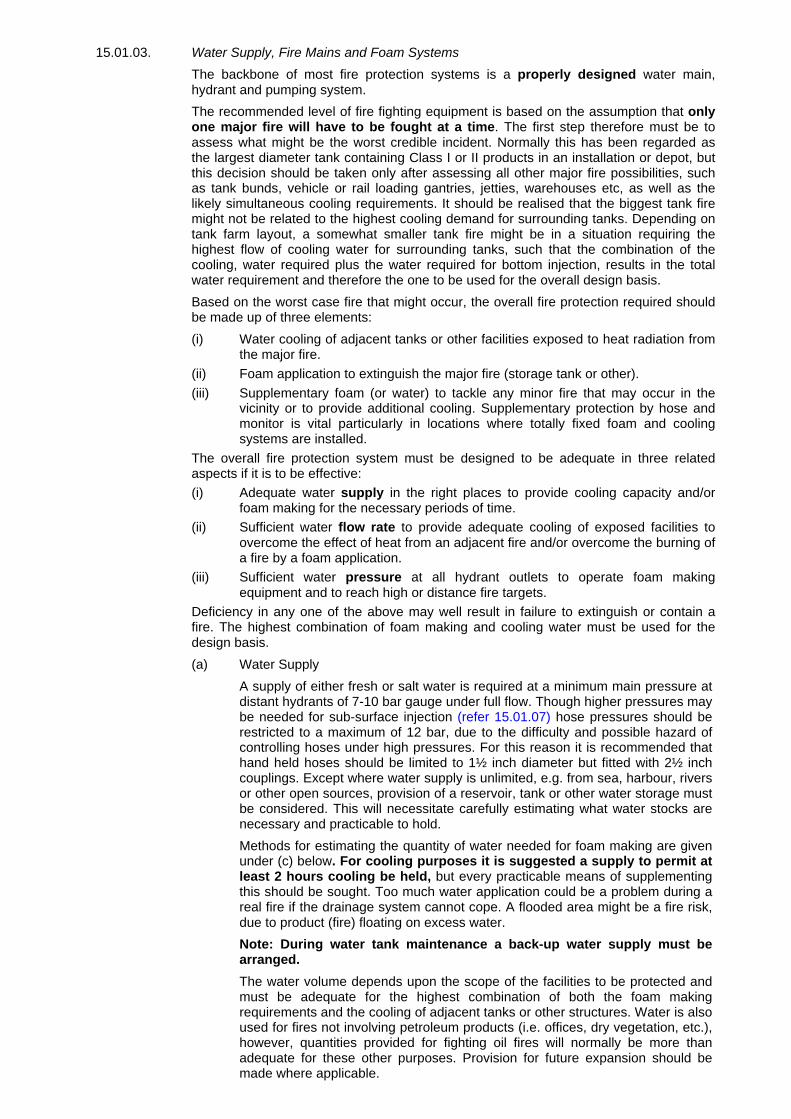
15.01.03. Water Supply, Fire Mains and Foam Systems
The backbone of most fire protection systems is a properly designed water main,hydrant and pumping system.
The recommended level of fire fighting equipment is based on the assumption that onlyone major fire will have to be fought at a time. The first step therefore must be toassess what might be the worst credible incident. Normally this has been regarded asthe largest diameter tank containing Class I or II products in an installation or depot, butthis decision should be taken only after assessing all other major fire possibilities, suchas tank bunds, vehicle or rail loading gantries, jetties, warehouses etc, as well as thelikely simultaneous cooling requirements. It should be realised that the biggest tank firemight not be related to the highest cooling demand for surrounding tanks. Depending ontank farm layout, a somewhat smaller tank fire might be in a situation requiring thehighest flow of cooling water for surrounding tanks, such that the combination of thecooling, water required plus the water required for bottom injection, results in the totalwater requirement and therefore the one to be used for the overall design basis.
Based on the worst case fire that might occur, the overall fire protection required shouldbe made up of three elements:
(i) Water cooling of adjacent tanks or other facilities exposed to heat radiation fromthe major fire.
(ii) Foam application to extinguish the major fire (storage tank or other).(iii) Supplementary foam (or water) to tackle any minor fire that may occur in the
vicinity or to provide additional cooling. Supplementary protection by hose andmonitor is vital particularly in locations where totally fixed foam and coolingsystems are installed.
The overall fire protection system must be designed to be adequate in three relatedaspects if it is to be effective:(i) Adequate water supply in the right places to provide cooling capacity and/or
foam making for the necessary periods of time.(ii) Sufficient water flow rate to provide adequate cooling of exposed facilities to
overcome the effect of heat from an adjacent fire and/or overcome the burning ofa fire by a foam application.
(iii) Sufficient water pressure at all hydrant outlets to operate foam makingequipment and to reach high or distance fire targets.
Deficiency in any one of the above may well result in failure to extinguish or contain afire. The highest combination of foam making and cooling water must be used for thedesign basis.
(a) Water Supply
A supply of either fresh or salt water is required at a minimum main pressure atdistant hydrants of 7-10 bar gauge under full flow. Though higher pressures maybe needed for sub-surface injection (refer 15.01.07) hose pressures should berestricted to a maximum of 12 bar, due to the difficulty and possible hazard ofcontrolling hoses under high pressures. For this reason it is recommended thathand held hoses should be limited to 1½ inch diameter but fitted with 2½ inchcouplings. Except where water supply is unlimited, e.g. from sea, harbour, riversor other open sources, provision of a reservoir, tank or other water storage mustbe considered. This will necessitate carefully estimating what water stocks arenecessary and practicable to hold.
Methods for estimating the quantity of water needed for foam making are givenunder (c) below. For cooling purposes it is suggested a supply to permit atleast 2 hours cooling be held, but every practicable means of supplementingthis should be sought. Too much water application could be a problem during areal fire if the drainage system cannot cope. A flooded area might be a fire risk,due to product (fire) floating on excess water.
Note: During water tank maintenance a back-up water supply must bearranged.
The water volume depends upon the scope of the facilities to be protected andmust be adequate for the highest combination of both the foam makingrequirements and the cooling of adjacent tanks or other structures. Water is alsoused for fires not involving petroleum products (i.e. offices, dry vegetation, etc.),however, quantities provided for fighting oil fires will normally be more thanadequate for these other purposes. Provision for future expansion should bemade where applicable.

The routing and extent of the fire main system plus the number and location ofhydrants must be carefully chosen so as to provide water for foam making andcooling of adjacent tanks or facilities at all significant potential fire targets.Flushing connections to clear sediment should be provided at intervals notexceeding 75 m and should allow for a flushing velocity of 2.5 m/sec minimum.
Water hydrants, each with two outlets, should be sited strategically throughoutthe installation, at distances of between 30 and 50 m from the items to beprotected - allowing for the possibility that access to any fire may be restrictedby prevailing winds and/or the fire situation itself being limited to only oneavenue of attack. The aim should be to restrict hose strings to two or threestandard (25 m) lengths in order to minimise pressure losses and the time takento connect hoses. Selection of hydrant valves with low pressure drop will helpconserve main water pressures.
In tank farms hydrant off-take points should be positioned so as to be accessiblein the event of all fire incidents, including bund fires.
Water lines for tank cooling should be above ground inside the bund for ease ofinspection and maintenance, also to prevent any damage from tank settlement.Previous editions of this manual advocate they should be buried, this is nolonger the case.
Block valves should be incorporated in the ring main where it may beconsidered useful to be able to isolate sections of the main, should it becomedamaged.
(b) Water Flow Rate - Cooling (Appendix 15.01.05)
Fixed cooling is required for fixed roof tanks holding Class I, II (2) or III (2)products and, in addition, for tanks holding Class II (1) and III (1) productswhere these might become endangered by adjacent fires. Class I, II (2) and III(2) tanks should be fitted with water spray or deluge systems to provideimmediate all-over cooling, whereas Class II (1) and III (1) tanks can be cooledusing water hoses or monitors from the ground on the exposed sides onlyprovided the reach of the equipment can cover the tanks, failing this a spray ringshould be fitted to the tank shell.
The term sprinkler system is normally applied to indoor systems in offices orbuildings to combat Class 'A' fires and the water droplets are larger than a tankroof/Shell spray system.
The design of a tank farm cooling system requires careful considerations of theseveral variables such as different combinations of tanks to be cooled, variationin size and type of fire, products involved, wind conditions, presence of possiblefire in the bund, and changes that take place during a fire. No single waterapplication rate will cater exactly for all fires but careful design and operationcan approach the ideal. A critical point is that the total water supply has to beshared simultaneously with the demands of the foam making system used forfire fighting and for cooling where applicable.
A manually activated (e.g. new project) fixed cooling water system with aminimum application rate of 1.7 litres/min/m² of exposed surface isrecommended for tanks spaced in accordance with safety distances given in03.05.06. This will give a heat barrier and cooling effect that can normally beturned on promptly thus leaving personnel free to carry out other fire fightingduties. (For LPG requirements see the LPG Manual).
Depending on the development of a fire it may become a tactical requirement tosupplement this basic level for a particularly exposed surface by reducingapplication to a less exposed surface during an actual fire. Such applicationwould not necessarily require the total design cooling water rate to exceed 1.7litres/min/m². It would be applied by utilising hoses and/or monitors wherever theamount of fixed spray water is inadequate, for example, on any part of a tankshell 'This would be evident if all cooling water on exposed shell or roof turnsinto steam, some parts of the shell are not receiving water, the shell metal isdiscolouring from the effect of heat, vapour and/or flames are seen issuing fromroof pressure/vacuum valves, or total water flow and pressure are judged to beinadequate.

It takes careful design and operation to produce a tank farm spray system thatgives close to 1.7 litres/min/m² on all possible combinations of tanks. Onesolution for setting and controlling spray flow rates is to fit pressure gaugesdownstream of each spray line control valve. The pressure gauge dial can bemarked with the pressure reading known by previous trials to give the desiredwater flow rate to that particular tank. As flow and pressure conditions varyduring a fire, the sprinkler spray control valves can be adjusted so as tomaintain as closely as possible the various design flow rates. Such valvesshould of course be located behind a fire barrier/screen outside bunds inpositions least likely to be engulfed by fire.
For improved cooling compared with the goose-neck deluge design, the use ofspray nozzles is recommended to be located on one or more tank top headersand round the top course of the tank shell. The minimum recommended sprayorifice size is 6 mm (to avoid blockage) which will achieve the application rate of1.7 litres/min/m² or more for tank roof and 17 litres/min/m of circumference ofshell for tank walls. For design details reference should be made to Appendix15.01.05.
A cooling water system designed for storage tank protection will normally havemore than sufficient capacity for handling cooling requirements for otherinstallations or depot facilities, for which hoses, nozzles and monitors would beused. LPG facilities are likely exceptions to this refer LPG Manual.
(c) Water Flow Rate - Foam Making
For foam making, the rate of application is related to the time taken to cover theentire burning surface with a blanket of foam. Because a proportion of the foammay be blown away by wind or heat updraft or deflected by obstructions and afurther proportion of the foam that reaches the burning surface is continuallybeing destroyed or consumed by the fire, there is a minimum or thresholdapplication rate on the actual target which must be achieved to extinguish thefire at all. The application rate at the target depends on the distance of theequipment to the target i,e, the generation rate x efficiency.
In the following guide-lines which are based on British Standard BS 5306Section 6.1:
• Foam solution application rates (1/min/m²) are the minimum flow rates (inlitres per minute per square metre of fire area) of foam solution on the fire(water plus concentrate but not yet aspirated) required to achieve extinction.
• Efficiency to obtain from the equipment the application rate at target.• Minimum discharge times are the lengths of time foam must be applied at
the minimum flow rates to achieve extinction.
Thus these three parameters dictate the supplies (in litres or m3) of water andfoam concentrate that must be held in readiness in order to fight the differenttypes of fire.
Such systems are used to provide protection against:
• Small local fires in bunds.• Spill fires (see also (v) Foam spray systems).• Small storage tanks (not greater than 6 metres high or 9 metres diameter).• Supplementary protection for large tanks equipped with sub-surface foam
(base injection) systems.
Minimum foam solution application rates:
• Small tank fires: 6.5 litres/min/m²• Other fires: 6.5 litres/min/m²
The above figures refer to quantities at the apparatus, it follows that a lesseramount will reach the target.
Minimum application times:
• Tanks - Class I and II products: 60 minutes Class III products: 45 minutes• Bunds, all products: 60 minutes• Spills, all products: 15 minutes
Minimum number of supplementary branch pipes and discharge times:

Tank
dia (m)
No
branch pipes (400 1/m)
Discharge
times (mins)
Less than 10 1 10
10 to 20 1 20
20 to 30 2 20
30 to 40 2 30
Over 40 3 30
(ii) Foam pourer systems
Such systems are used for the protection of fixed and floating roof tanksby applying foam gently onto the liquid surface in the following ways:
• Against the internal shell of a fixed roof storage tank.• Into the seal area of a floating roof tank.
Minimum foam solution application rates:
• Fixed roof tanks or bunds 4.0 litres/min/m².• Into the seal area of a floating roof tank.
Minimum foam solution application rates:
• Fixed roof tanks or bunds 4.0 litres/min/m².• Floating roof tanks 20.0 litres/min/m².
Minimum discharge times:
• Tank - Class I and II products 45 minutes.Class III (white) products 30 minutes.
• Tank roof seals 20 minutes.• Bunds 60 minutes (area 10 m x 10 m).Minimum number of foam pourers for fixed roof tanks or bunds:
Tank dia (m) Number of pourers Bund area (m²)Less than 24 1 45024 to 36 2 102036 to 42 3 138042 to 48 4 181048 to 54 5 2290Over 54 6 2380
(Foam pourers for bunded areas would normally be by portable branchpipe.)
(iii) Sub-surface foam systems (base injection)
Such systems are used for the protection of fixed roof storage tanks inwhich foam is injected near the base of the tank, and rises to thesurface through the product in the tank (see section 15.01.07 for furtherinformation).Minimum foam solution application rates:• Class I, II and III products: 4.0 litres/min/m² (excluding black oils or
bitumen)*.Minimum discharge times:• Class I and II products: 45 minutes.• Class III (white off) products: 30 minutes.
*Fires in tanks containing black oils or bitumen can give rise to hot zones of over100 °C which may cause boil over as foam passes through them.
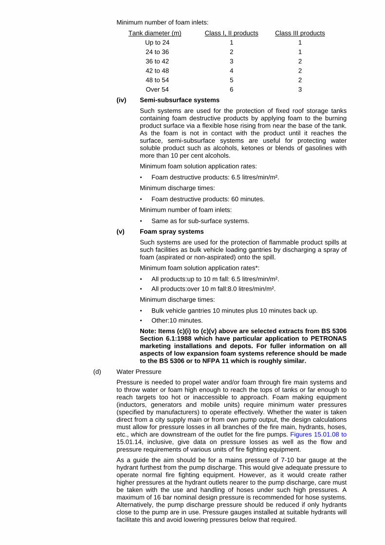
Minimum number of foam inlets:
Tank diameter (m) Class I, II products Class III productsUp to 24 1 124 to 36 2 136 to 42 3 242 to 48 4 248 to 54 5 2Over 54 6 3
(iv) Semi-subsurface systems
Such systems are used for the protection of fixed roof storage tankscontaining foam destructive products by applying foam to the burningproduct surface via a flexible hose rising from near the base of the tank.As the foam is not in contact with the product until it reaches thesurface, semi-subsurface systems are useful for protecting watersoluble product such as alcohols, ketones or blends of gasolines withmore than 10 per cent alcohols.
Minimum foam solution application rates:
• Foam destructive products: 6.5 litres/min/m².
Minimum discharge times:
• Foam destructive products: 60 minutes.
Minimum number of foam inlets:
• Same as for sub-surface systems.
(v) Foam spray systems
Such systems are used for the protection of flammable product spills atsuch facilities as bulk vehicle loading gantries by discharging a spray offoam (aspirated or non-aspirated) onto the spill.
Minimum foam solution application rates*:
• All products:up to 10 m fall: 6.5 litres/min/m².• All products:over 10 m fall:8.0 litres/min/m².
Minimum discharge times:
• Bulk vehicle gantries 10 minutes plus 10 minutes back up.• Other:10 minutes.
Note: Items (c)(i) to (c)(v) above are selected extracts from BS 5306Section 6.1:1988 which have particular application to PETRONASmarketing installations and depots. For fuller information on allaspects of low expansion foam systems reference should be madeto the BS 5306 or to NFPA 11 which is roughly similar.
(d) Water Pressure
Pressure is needed to propel water and/or foam through fire main systems andto throw water or foam high enough to reach the tops of tanks or far enough toreach targets too hot or inaccessible to approach. Foam making equipment(inductors, generators and mobile units) require minimum water pressures(specified by manufacturers) to operate effectively. Whether the water is takendirect from a city supply main or from own pump output, the design calculationsmust allow for pressure losses in all branches of the fire main, hydrants, hoses,etc., which are downstream of the outlet for the fire pumps. Figures 15.01.08 to15.01.14, inclusive, give data on pressure losses as well as the flow andpressure requirements of various units of fire fighting equipment.
As a guide the aim should be for a mains pressure of 7-10 bar gauge at thehydrant furthest from the pump discharge. This would give adequate pressure tooperate normal fire fighting equipment. However, as it would create ratherhigher pressures at the hydrant outlets nearer to the pump discharge, care mustbe taken with the use and handling of hoses under such high pressures. Amaximum of 16 bar nominal design pressure is recommended for hose systems.Alternatively, the pump discharge pressure should be reduced if only hydrantsclose to the pump are in use. Pressure gauges installed at suitable hydrants willfacilitate this and avoid lowering pressures below that required.

15.01.04. Fire Pumps
Where water pumping has to be provided, but may be supplemented by outside helpwithin reasonable time, it is recommended that the total water requirement be shared byat least two identical pumps each providing not less than 60 per cent of the total. Whereno outside help is available then three pumps should be capable of providing 3 x 60 percent of the full requirement. While the main pump may be electrically driven for quickstarting, ease of operating and remote starting possibility, the second (stand-by) pumpshould have a separate power source, preferably a diesel engine, particularly whereelectric supplies may be unreliable. All wiring and switch gear should be independent ofall other electrical circuits and protected so that the fire pumps remain unaffected in anemergency causing damage or necessitating the isolation of normal circuits.
*Rates apply to all types of foam concentrate(P, FP, FFFP and AFFFF) however only FFFP andAFFF concentrates can be used for non-aspirated spray system, at 4.0 and 6.5 litres/min/m² inplace of the 6.5 and 8.0 rates above.
Detailed and clearly printed instructions for starting and operating each fire pump shouldbe displayed at the pump site. As many of the installation staff as may be required for anemergency should receive training in the use of the equipment.
The site chosen for fire pumps should be strategic (note:
prevailing wind), separated from each other, and safe from vandalism, sabotage and anyforeseeable source of fire (e.g. drainage outlets). Particular care must be taken toprovide separate pump suction intakes for each pump of adequate size for the designmaximum flow rate, positioned so as to be always below lowest water/tide level,protected by a screen from damage or clogging with vegetation or other matter and,ideally, provided with a means to back-flush particularly in rivers or harbours.
Manufacturers of diesel and electric-driven fire pumps sets usually offer certain modelsto meet accepted industry design standards. The standard laid down by the National FirePrevention Association (NFPA 20) is particularly stringent and would certainly meet theoperating requirements of marketing installations or the requirements of insurancecompanies (e.g. UL, Factory Mutual).
15.01.05. Fire Hoses and Accessories
Fire hoses and accessories such as stand pipes, branch pipes, water and foammonitors, inductors, generators, nozzles and couplings should be provided as necessary,see Figures 15.01.10 and Figure 15.04.13.
Fire equipment boxes (hydrant boxes) should be distributed throughout the installationand should each contain sufficient equipment to enable an immediate initial hose attackto be mounted from the hydrants nearest to potential fire sites.
Hose couplings should conform to local national standards. If such standards do notexist it is recommended use by made of the 2.5 inch instantaneous couplings describedin MESC 96.22.10 and Figure 15.01.13. In any case, equipment should be compatiblewith that used by local fire services and other oil companies.
15.01.06. Foam and Water Monitors
These units (see Figure 15.01.11 for example) are normally chosen according to thedesired capacity required. Most models are dual purpose - i.e. they can be used to throwwater for cooling purposes or foam for fire fighting or blanketing product spillages.Smaller, portable units are usually more appropriate for marketing installations anddepots as they can be man-handled by one or two men, and are relatively easy to set upin most locations. Larger units usually have to be mounted on wheeled trolleys whichrequire some form of transport and therefore better means of access to targets, or theycan be fixed e.g. at filling gantries.

15.01.07. Sub-surface(Base Injection) And Semi-sub-surface foam For Storage Tanks
(a) General Description
In the sub-surface foam system, fire fighting foam is injected through one ormore inlets in the tank shell near the base of the tank. The injected foam thenrises freely to the surface to form a stable fire-resistant blanket and in theprocess sets up circulation currents in the product which remove heat from theburning surface, see Figure 15.01.17. Unlike foam applied from the outside ofthe tank by branch pipe or monitors, which can be blown away by the wind orthe hot up-draught of the fire or can be obstructed by a damaged roof structure,sub-surface foam suffers hardly any wastage and practically all of it reaches theproduct surface. A further advantage is that the inlets being at the bottom of thetank are relatively safe from damage. The following summary lists a number ofadvantages and limitations in using sub-surface (base injection) and semi-surface foam in storage tanks:
Advantages:
• Rapid response with minimum demand on resources, water supply, foamcompound and manpower.
• High resistance of the system to damage during tank explosion or fire.• Design application rates of foam are achieved with 100 per cent of the foam
reaching the tank.• Circulation of cold fuel dissipates hot fuel layers near the burning surface
and aids extinction.• The system is simple to operate and maintain.• Existing product pipelines into the tank can often be used as inlets for foam.• Suitable for unskilled operation or automatic initiating at a safe distance from
the fire.
Limitations:
• Sub-surface cannot be used with polar solvents or water miscible liquids, insuch cases semi-subsurface may be used.
• Not suitable for open top floating roof tanks where foam distribution may beuneven, due to the configuration of the roof.
• Foam inlets must be above any water layer in the tank.• Extra inlets to the base of the tank may be required if existing product lines
cannot be used.• See also 15.01.07 (b) iii and 15.02.01 (h).
Sub-surface foam is not feasible for tanks containing:
(i) Black oils or bitumen - because, if they burn for more than 5 to 10minutes before injection of foam starts, hot zones with temperaturesexceeding 100 °C are formed which are likely to convert the foam to steamand cause dangerous frothing or boil-over; for white oils the hot zones stayfar enough below 100 °C for this not to occur.
(ii) Water soluble chemical products - since water-based foam is destroyedas it bubbles through such products, and in addition the need for gentleapplication of alcohol resistant foams precludes application by baseinjection.
One possible solution to both these obstacles is semi-sub-surface foam in whichfoam is injected through a sealed container which is attached to the outside ofthe tank shell and which contains a folded hose (see Figure 15.01.20). The hoseis forced out of the container by the foam/air pressure breaking the seal, and ispushed up through the product to the burning surface where it expels the foamto extinguish the fire. Thus the foam does not come into contact with the productuntil it reaches the product surface. PETRONAS experience with this device,available from two different suppliers has proved to be effective, and isrecognised in both British and NFPA standards.
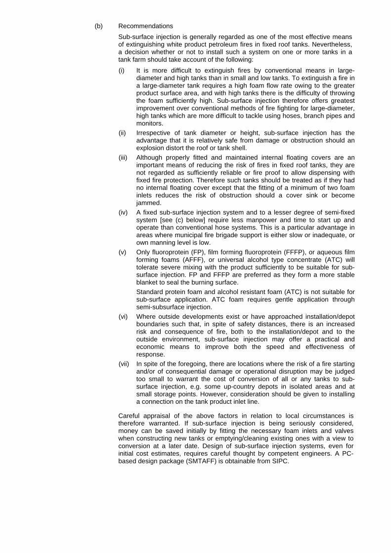
(b) Recommendations
Sub-surface injection is generally regarded as one of the most effective meansof extinguishing white product petroleum fires in fixed roof tanks. Nevertheless,a decision whether or not to install such a system on one or more tanks in atank farm should take account of the following:
(i) It is more difficult to extinguish fires by conventional means in large-diameter and high tanks than in small and low tanks. To extinguish a fire ina large-diameter tank requires a high foam flow rate owing to the greaterproduct surface area, and with high tanks there is the difficulty of throwingthe foam sufficiently high. Sub-surface injection therefore offers greatestimprovement over conventional methods of fire fighting for large-diameter,high tanks which are more difficult to tackle using hoses, branch pipes andmonitors.
(ii) Irrespective of tank diameter or height, sub-surface injection has theadvantage that it is relatively safe from damage or obstruction should anexplosion distort the roof or tank shell.
(iii) Although properly fitted and maintained internal floating covers are animportant means of reducing the risk of fires in fixed roof tanks, they arenot regarded as sufficiently reliable or fire proof to allow dispensing withfixed fire protection. Therefore such tanks should be treated as if they hadno internal floating cover except that the fitting of a minimum of two foaminlets reduces the risk of obstruction should a cover sink or becomejammed.
(iv) A fixed sub-surface injection system and to a lesser degree of semi-fixedsystem [see (c) below] require less manpower and time to start up andoperate than conventional hose systems. This is a particular advantage inareas where municipal fire brigade support is either slow or inadequate, orown manning level is low.
(v) Only fluoroprotein (FP), film forming fluoroprotein (FFFP), or aqueous filmforming foams (AFFF), or universal alcohol type concentrate (ATC) willtolerate severe mixing with the product sufficiently to be suitable for sub-surface injection. FP and FFFP are preferred as they form a more stableblanket to seal the burning surface.Standard protein foam and alcohol resistant foam (ATC) is not suitable forsub-surface application. ATC foam requires gentle application throughsemi-subsurface injection.
(vi) Where outside developments exist or have approached installation/depotboundaries such that, in spite of safety distances, there is an increasedrisk and consequence of fire, both to the installation/depot and to theoutside environment, sub-surface injection may offer a practical andeconomic means to improve both the speed and effectiveness ofresponse.
(vii) In spite of the foregoing, there are locations where the risk of a fire startingand/or of consequential damage or operational disruption may be judgedtoo small to warrant the cost of conversion of all or any tanks to sub-surface injection, e.g. some up-country depots in isolated areas and atsmall storage points. However, consideration should be given to installinga connection on the tank product inlet line.
Careful appraisal of the above factors in relation to local circumstances istherefore warranted. If sub-surface injection is being seriously considered,money can be saved initially by fitting the necessary foam inlets and valveswhen constructing new tanks or emptying/cleaning existing ones with a view toconversion at a later date. Design of sub-surface injection systems, even forinitial cost estimates, requires careful thought by competent engineers. A PC-based design package (SMTAFF) is obtainable from SIPC.

(c) Type of System
Sub-surface foam injection facilities can be installed either as a fixed system inwhich all equipment is permanently in place or as a semi-fixed system based onportable or mobile foam generating equipment and hoses brought andconnected up at the time of the fire. With either system the foam can be injectedeither direct into the tank through dedicated foam inlets or via existing productlines. The choice of which system to use should be based on a cost versusbenefit analysis of the alternatives taking into account the advantages anddisadvantages given in the following descriptions.
(i) Semi-fixed System
The fixed part of the system consists of the foam line which runs fromoutside the tank bund to the tank inlet(s) and is fitted with suitablevalves and an inlet manifold to which the foam generators can beconnected when needed. Since the tank valve has to be open to permitfoam to enter, it must either be remotely operated or be left permanentlyopen, in which case it is necessary to fit a second steel tank valveoutside the bund and a bursting disc downstream between the tankvalve and check valve to contain the tank contents. If manually operatedthe valve outside the bund must be located and protected such that anoperator can get to it quickly and open it even when the tank and/orbund is on fire. A possible arrangement is shown in Figure 15.01.21.The foam concentrate, proportioners, and generators can be carried ina van or trailer and brought to a fire when required, for connection byhoses between the water supply hydrants and the foam lines. Foamgeneration is initiated by opening the water supply and foam line valvesand maintaining adequate supplies of water and foam concentrate.
The main advantage of the semi-fixed system is that only one set ofgenerators, proportioners and foam concentrate is needed to coverperhaps several tanks or different groups of tanks. This however carrieswith it the main disadvantage of the system which is that it obviouslytakes time to connect and start foam injection, and in addition a meansto transport the foam and equipment to the appropriate foam linemanifold must be provided and kept in constant readiness.Furthermore, suitable and protected access to every foam line ormanifold connecting point must be provided.
(ii) Fixed System
The foam line and valve requirements within the bund are much thesame as for the semi-fixed system, but outside the bund all foamproportioners and generators plus a foam concentrate tank or supplyline are installed as fixed parts of the system (see Figures 15.01.22 to15.01.24 inclusive).
An obvious advantage of the fixed system is the speed with which it canbe operated, since there is no delay while bringing up foam andequipment, connecting hoses, etc. A disadvantage is the cost of thegreater number of generators, proportioners and foam concentratetanks that may be required. However, judicious layout design canminimise this by grouping tanks so that each battery of generators andrelated equipment will serve several different tanks. One, two or at themost three such batteries will normally be sufficient to cover mostmarketing tank farms.
Generally, therefore, the fixed systems is to be preferred since theadditional cost is not large compared with the longer delay and lowerreliability of the semi-fixed system which requires more manpower andthe need to maintain equipment in constant readiness.
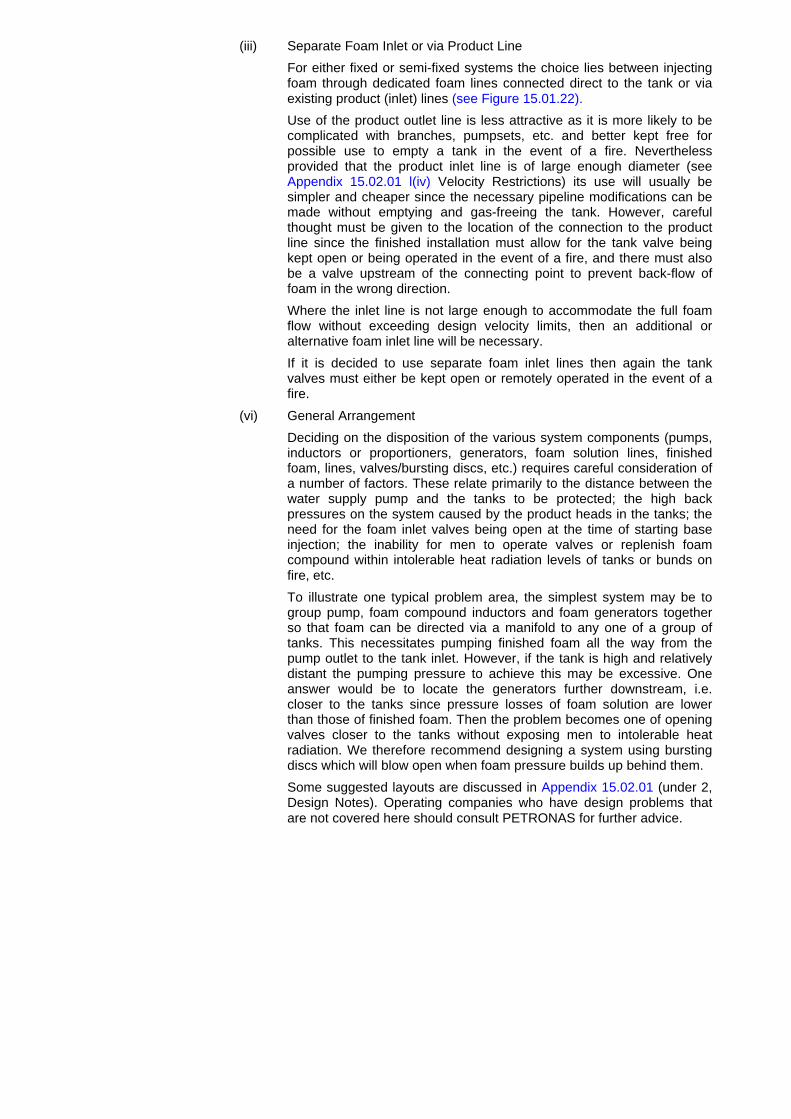
(iii) Separate Foam Inlet or via Product Line
For either fixed or semi-fixed systems the choice lies between injectingfoam through dedicated foam lines connected direct to the tank or viaexisting product (inlet) lines (see Figure 15.01.22).
Use of the product outlet line is less attractive as it is more likely to becomplicated with branches, pumpsets, etc. and better kept free forpossible use to empty a tank in the event of a fire. Neverthelessprovided that the product inlet line is of large enough diameter (seeAppendix 15.02.01 l(iv) Velocity Restrictions) its use will usually besimpler and cheaper since the necessary pipeline modifications can bemade without emptying and gas-freeing the tank. However, carefulthought must be given to the location of the connection to the productline since the finished installation must allow for the tank valve beingkept open or being operated in the event of a fire, and there must alsobe a valve upstream of the connecting point to prevent back-flow offoam in the wrong direction.
Where the inlet line is not large enough to accommodate the full foamflow without exceeding design velocity limits, then an additional oralternative foam inlet line will be necessary.
If it is decided to use separate foam inlet lines then again the tankvalves must either be kept open or remotely operated in the event of afire.
(vi) General Arrangement
Deciding on the disposition of the various system components (pumps,inductors or proportioners, generators, foam solution lines, finishedfoam, lines, valves/bursting discs, etc.) requires careful consideration ofa number of factors. These relate primarily to the distance between thewater supply pump and the tanks to be protected; the high backpressures on the system caused by the product heads in the tanks; theneed for the foam inlet valves being open at the time of starting baseinjection; the inability for men to operate valves or replenish foamcompound within intolerable heat radiation levels of tanks or bunds onfire, etc.
To illustrate one typical problem area, the simplest system may be togroup pump, foam compound inductors and foam generators togetherso that foam can be directed via a manifold to any one of a group oftanks. This necessitates pumping finished foam all the way from thepump outlet to the tank inlet. However, if the tank is high and relativelydistant the pumping pressure to achieve this may be excessive. Oneanswer would be to locate the generators further downstream, i.e.closer to the tanks since pressure losses of foam solution are lowerthan those of finished foam. Then the problem becomes one of openingvalves closer to the tanks without exposing men to intolerable heatradiation. We therefore recommend designing a system using burstingdiscs which will blow open when foam pressure builds up behind them.
Some suggested layouts are discussed in Appendix 15.02.01 (under 2,Design Notes). Operating companies who have design problems thatare not covered here should consult PETRONAS for further advice.

(d) Operating Factors
To extinguish a fire successfully by sub-surface injection, three operationalfactors are particularly important:
(i) Foam solution must be supplied to the generators at or above thespecified minimum flow rate continuously until the fire is extinguished.Application at a lower rate for a longer duration of time will not generallyextinguish a fire. Additionally, if (perhaps through lack of foamconcentrate), injection has to be stopped before the fire is totallyextinguished, this will allow the flames to spread back across the productsurface thus losing all that one has gained up to that time. It is thereforeessential that the full requirement of foam compound is assembled orimmediately available before sub-surface injection operations start. (SeeAppendix 15.02.01).
(ii) The minimum inlet pressure specified for the high back-pressuregenerators used (7 bar) must be maintained continuously otherwiseinferior quality foam may be produced leading to extended extinctiontime or even failure to extinguish the fire. It is important therefore that,during the actual foam injection operation, significant changes in demandon the water supply, (which could upset the flow/pressure supply to thebase injection system) do not occur. This would require a minimum of 10bar upstream of proportioners to compensate for pressure and frictionlosses.
(iii) If variable foam inductors are considered necessary to permit the use ofdifferent concentrations of foam compound, they should preferably beset and sealed at the correct percentage. Alternatively, a clear signshould be posted directing the fire fighters to set the inductors at thecorrect percentage induction rate for the foam concentrate in use. If foamconcentrate is induced too slowly, poor foam will result; if induced to faststocks will be consumed wastefully and too little foam will be produced.
(e) Design and Equipment
Guidance on the design of sub-surface injection systems is given in Appendix15.02.01. Examples of typical foam generators and foam inductors are shown inFigures 15.01.16 to 15.01.18. A sketch showing the recommended tank inlet forbase injection is given in Figure 15.01.26.
A PC-based computer programme SMTAFF (refer Appendix 15.02.01(d)) hasbeen developed to carry out design calculations - given the necessary details oftank dimensions, layout, products stored, etc.

15.01.08. Foam Pourers For Floating Roof Tanks
Several types of proprietary foam pourers are available from suppliers, the currentrecommendation for group companies is illustrated in Figures 15.01.27 and 15.01.28.
The number of foam pourers per tank will depend on the diameter of the tank. Thelocation of the high pressure generator will depend on whether a wind girder is fitted tothe tank. Where a wind girder is installed it should be located as illustrated in Figure15.01.27. In such cases the dry riser should be located adjacent to the top landing of thestaircase. Dry risers should be hot dip galvanised internally and externally and flanged.The foam generator should be located horizontally at the top of the dry riser. Foamconcentrate can be injected through flexible hoses connected to the two 2½ inchconnections at the head of the staircase or from connections outside the bunded area. Ifadditional risers are required they should be positioned around the tank circumference atintervals not exceeding 30 m for Shell type nozzles. Other pourers of non 'Shell'design should be installed at locations not exceeding a pitch of 12 m. These should beinstalled as illustrated in Figure 15.01.27 with the high pressure generator installedoutside the bunded area. Also, if the tank is not fitted with a wind girder this drawingshould be followed.
In either case the piping leading to the dry riser should be laid above ground and overthe top of the bund and not through the bund wall.
The equipment described above has proved to be effective in extinguishing actual rimfires in floating roof tanks even when the product level is low and the roof is in its nearbottom location as illustrated in Figure 15.01.29.
Rim fires are sometimes difficult to detect, particularly during daylight hours when theroof is in a low position or in unmanned installations. Self contained detection systemsare available from suppliers, these are mounted on the roof of a floating roof tank. Apolyethylene tubing is placed circumferentially around the rim of the seal, this tubing ischarged with nitrogen from a cylinder mounted in a cabinet. If a fire breaks out in the rimseal area the plastic hose melts allowing the nitrogen to escape; this is detected by asensor which in turn activates a visible/audible alarm (See Figures 15.01.30).
15.01.09. Distinctive Colouring
Fire fighting equipment should be painted distinctively. Red is the accepted basic colour(Shell standard colour number 11), but each type of extinguisher may be paintedwholly or partly in other colours for the purpose of ready identification, and a suggestedarrangement used by extinguisher suppliers is as follows:Water RedFoam CreamCarbon dioxide BlackDry chemical powder BlueInstruction labelling with black letters on a yellow background is generally more clearlyvisible than other colour combinations.Notices indicating the location of equipment should have white letters on a redbackground. Fire boxes containing hoses, branch pipes and other equipment should bepainted red.Fire precautions notices have red letters on a white background, e.g. no smoking, etc.Notwithstanding the above colour coding, it is important that the appropriate extinguishershould be sited in the vicinity where it can be used on the hazard for its designedpurposes.
15.01.10. Fire Alarms And Emergency Calls
Suitable audible alarms must be provided with actuating points (switches) located andclearly marked in strategic positions, e.g. loading gantries, jetties and berths, pumpstations, dispatch office, etc. Such alarms must, of course, be audible (or visible) at alllocations - particularly remote ones such as berths and jetties. There should be norestriction as to who may sound an alarm since delays in calling for help can be critical.A notice on which the telephone numbers of the fire and emergency services are clearlyrecorded should be displayed near the telephone at the gate house or other controlcentres.All personnel, including contractors, must know what to do in the event of a fire alarm(see Plant Operating Manual 01.04.05) and fire alarm equipment should be regularlytested, e.g. at monthly fire practices, to ensure they work and can be heard at all workinglocations.

15.02.00. LEVELS AND TYPE OF PROTECTION
15.02.01. Tank Farms
The level and type of fire protection required for a tank farm depends on a number offactors including tank farm location, surroundings, size and number of tanks, strategicimportance, overall storage capacity and classes of product stored. In the followingguidance the requirements of each class of product and each type of tank areconsidered separately, since in many tank farms segregated product groups can betreated differently for convenience and cost effectiveness. Where products of differentclasses are stored in adjacent or intermingled tankage then naturally the impact of themost highly flammable (Class I) product must be given top priority.
While the part to be played by any local fire service in the event of a fire must be takeninto account, the type and scale of fixed or mobile facilities will depend on the followingguidelines.
(a) Class III(1) Product Storage
Fire risk is very low, however, at least sufficient hydrants (each 1 000 litres/min)for 2 litres/min/m² fog needs to be provided. Should storage contain highlycritical strategic stocks then water may be provided for cooling and/or extinctionusing portable equipment (pumps, hoses and monitors) preferably provided bythe local fire brigade. For black oil products sub-surface foam (base injection) isnot recommended due to the hazard associated with hot zones of over 100 °Cwhich can form within as little as ten minutes after a tank fire starting.
Notwithstanding the above, gas oil tanks located adjacent to Class I storage,should be treated as Class I tankage to facilitate possible product changes inthe future.
(b) Class III(2) Product Storage
High viscosity products stored at temperatures at or above their flash points(e.g. bitumens or fuel oils) present sufficient fire risk to justify a higher level ofprotection than required for Class III(l) products.
Dependent on the strategic situation the ability to extinguish or contain a fireshould be available. Foam, applied by hoses and monitors, provides a means ofapplying water in the finely divided state necessary, particularly for bitumen tankfires, to minimise the risk of boil over. Alternatively for less strategic stocks,containment can be achieved by applications of water to cool adjacent tankage;even for the burning tank itself provided it is not insulated, water applied to theshell can help to cool the contents and thus reduce the fire. As for Class III(1)(black oil) products sub-surface foam is not recommended.
(c) Class II(1) Product Storage
Due to their range of flashpoints (21 °C to 55 °C) Class II products can be fairlyreadily ignited at other than the coldest ambient temperatures and thereforeconsideration should be given to fixed foam facilities also taking into accountstrategic importance, environment adjacent to tanks, total quantity stored andtank sizes.
In normal marketing installations and depots, fixed foam should be provided,though storage tanks less than 10 metres in height can be protected by mobileequipment provided sufficient, trained manpower is readily available.
Where fixed foam pourers or sub-surface foam is installed, it is important thatsupplementary (back-up) protection (foam and water) be provided to combatany bund or spillage fires that could occur in the tank farm area.
Fixed cooling systems should also be provided if there is risk of producttemperatures being raised by radiation from an adjacent fire within or fromoutside the tank farm. In some less significant locations with minimal exposureto potential fires manual cooling using hoses and monitors could suffice.

(d) Class I and II(2) Product Storage
At all ambient temperatures these products produce flammable vapours andfixed fire fighting and cooling facilities should be provided.
Sub-surface foam (base injection) is generally recommended as the mosteffective system for extinguishing Class I product fires, (see also Section13.6.7). internal floating covers (IFC's), although they reduce vapour emission,are not regarded as offering sufficiently reliable security against fires to allowdispensing with fixed foam fire protection. To reduce the risk of sunken ordamaged IFC obstructing foam application, the design of the foam systemshould include at least two foam inlets.
Fixed cooling systems should also be provided to combat the effect of heatradiation from adjacent tanks or other facilities on fire. Manual cooling systemsare not normally regarded as adequate protection for Class I and II(2) storagedue to the time they take to get started, and the manpower required.
(e) Mixed Class Tankage
The type and level of protection are determined largely by the presence andproximity of Class I, II(2) and III(2) products. Separate compounds for Class Inproducts may be treated separately provided they are not exposed to radiationfrom other tanks (Class I, II) on fire.
(f) Floating Roof Tanks
The most common fire in a floating roof tank is a seal or rim fire. A dry riserinstalled up the tank shell with top pourers to supply foam into the seal spacecan be used. An adequate alarm system should be provided (see 15.01.32 N2unit for 'poly-flo' line detection).
(g) Fixed Roof Tanks
For tanks requiring fixed foam facilities, sub-surface foam (base injection) ispreferred due to its greater reliability and speed. Section 15.01.07 details theadvantages and limitations of sub-surface systems, whilst Appendix 15.02.01addresses the design and equipment in sub-surface systems.
A PC-based design package called SMTAFF and a PC program for heatradiation calculations is available from SIPC. (Refer Appendix 15.02.01(d)).
Top foam pourers can still provide effective protection for some less criticalsituations mentioned above, as well as for tanks containing foam destructiveproducts [e.g. alcohols, ketones and gasoline blends with high (more than 10per cent) oxygenate contents] which require gentle surface application of foamrather than the intimate contact inherent in sub-surface foam systems.
An alternative system for foam-destructive products is semi-subsurface foam. Inthis system foam is injected through a hose fixed near the base of a tank whoseoutlet floats to the top of the product during operation thus keeping foam andproduct separate, prior to gentle application from the hose. See Figure 15.01.20.
(h) Fixed Roof With Internal Floating Cover (IFC)
Although an IFC reduces the vapour emissions in a fixed roof tank it is notconsidered sufficiently reliable or fire proof to enable any reduction in the levelof fire protection required. Such tanks should therefore be treated as normalfixed roof tanks for fire protection purposes [see (g) above].
Though not recommended, where steel pan IFCs exist, sub-surface foam is notsuitable, as a sunken pan could obstruct foam inlets. Any such tanks may beprotected by top foam pourers.

15.02.02. Bulk Vehicle Loading Gantries
For loading bays handling Class I, II(2) or III(2) products, the fire main and hydrantssystem should run close enough (20 mm minimum) to permit application of foam and/orwater from at least two directions. This is to facilitate access in the event of obstructionby abandoned vehicles, as well as difficulties caused by wind direction.
At unmanned or low level manpower installations and depots consideration should begiven to installing fixed foam or water deluge systems at loading gantries with more thanfour loading positions. The intensity of use (number of vehicles loading/waiting at peaktimes), the level of control of safe loading operations (proportion of PETRONAS tonon-PETRONAS drivers), the effectiveness of emergency spillage/fire response, andof the standard design (refer the Loading and Discharge Manual - Road) are all factors which will influence the decision.
Bottom loading gantries with overfill protection and other automated controls areconsidered less vulnerable, but fixed systems may be justified on the basis of strategicimportance, large size of facility, local authorities' views and environmentalconsiderations.
The advent of unmanned depots is reducing the degree of human control andintervention to the extent that automatic response in the event of a fire is becoming anecessity. For this reason loading gantries in unmanned locations should be equippedwith:
• An automatic fire detection system capable of:
- Quickly detecting flames in the gantry area.- Turning off power on-site except emergency lighting, communications equipment
and fire fighting facilities.- Raising an alarm at the local fire service.- Signalling to the main terminal/administration centre that a fire has been
detected.
• An automatic fixed foam sprinkler linked to the above system and capable of firesuppression by spraying foam over the gantry area.
• An emergency stop valve at each loading bay as for conventional depots.
Note: Fire detectors should be mounted and located so that the entire area isunder surveillance. Detectors should be highly resistant to deceptive phenomena,such as headlamps and reflected sunlight; however very sophisticated detectors(e.g. infra-red light beams) are not necessary for this purpose.
As such automatic spray systems only cover the immediate gantry area, protection willstill be needed to tackle possible fires that may occur or spread to parked vehicles andother facilities in the vicinity of the gantry.
For fuller details of the requirements and design of gantry fire protection systemsreference should be made to PETRONAS.
For a small number of bays or filling points handling only Class II(1) or Class III(1)products, mobile wheeled units should give sufficient protection.
15.02.03. Rail Tank Wagon Filling or Discharge Facilities
Many of the same considerations apply as far as for road loading facilities (above),except that human involvement during loading/discharge operations is normally limitedthough they are normally PETRONAS staff. As a minimum the ability to lay down foam atany part of the area is a necessity at the rate specified for spills, (i.e. 5.0 litres/min/m²foam solution reference 15.01.03 above) plus separate application of cooling water onexposed railcars or other plant.
As for vehicle facilities thought should be given to fixed/automatic systems at least forloading operations since the strategic importance of such facilities is likely to be high.

15.02.04. Berths And Jetties
(See International Safety Guide for Oil Tankers and Terminals ISGOTT).
The type and quantity of fire fighting equipment should be based on an assessment ofthe total risk and be related to the size and location of the berth, the layout of theinstallation, the types and throughputs of product handled, and the hazard to and fromadjacent or jointly operated facilities. The aim is to provide adequate protection for thejetty in the event of a shore or tanker fire, in particular the loading and unloading armsand hoses, and related pipework.
Such a system should also be capable of providing assistance to a berthed tankerparticularly in the area of its manifold. Fire on a berthed tanker can usually be foughtmore easily if the tanker is kept alongside the wharf or jetty, and at larger ports theharbour authorities should preferably provide sufficient floating fire fighting equipment totackle a ship fire and/or supplement shore fire fighting efforts. For this, easily accessiblehose connections should be provided to enable tugs' fire pumps to charge theinstallation fire main if necessary.
At installations which have jetty/wharf berths handling Class I and II cargoes andaccommodating ships of 18 000 tonnes and over, or receiving more than 60 ships peryear with a throughput exceeding a half million tonnes per year, fire protection facilitiesshould be provided as follows:
(a) Fire Mains
A fire water main to each berth or jetty head, together with hoses andequipment. Water mains should terminate in double hydrants. There should beone double hydrant for each 60 m length of the largest ship which the jetty canaccommodate. Hydrants and fire equipment must be sited to permit the mainconcentration of fire fighting to be aimed at the shore/ship manifold area, but atthe same time providing some cover throughout the length of the berth.
Accessibility and protection from exposure to fire must also be considered.
Based on the maximum size of tanker acceptable at the berth, the water mainshould be capable of supplying 50m3/hour for each 30 m length of ship at aminimum pressure of 10 bar under full flow conditions at the most unfavourablysited hydrants, up to a maximum total flow rate of 250 m3/hour. This will permitthe use of mechanical foam generators (see Figure 15.01.14 or high-pressurespray nozzles, see MESC 96.28.20. Hydrants should not be located too close torisk areas (20 m minimum).
Fire towers are not normally recommended for marketing installations. Wherefire towers have been erected, one or more branch lines should be installed tosupply water to fixed monitors, installed on top of the tower. The monitorsshould preferably be dual controlled (local and remote) and should be able tothrow jets of water over a distance equal to the beam of the largest tanker likelyto use the berth, and should be capable of delivering water, fog or spray asrequired.
Water jets are intended for dealing with fires on ship's superstructures untilclose range fire fighting can be carried out. Fog or spray jets are particularlyuseful for cooling purposes and to provide a protective curtain or water to assistpersonnel in gaining access to or escaping from the ship.
Water supplies may be from the harbour or other open source, or from anextension to the installation fire water main.
Where jetties or berths are remote from installations it may be necessary toinstall separate pumps or connections for the local fire service (shore orharbour) to connect their pumps. Where the jetty or berth is either shared oroperated by third parties (other oil companies, harbour authorities) specificarrangements must be made to ensure a viable fire protection system, properlymaintained and manned when required.
(b) Stocks of Foam Compound
Foam compound should be readily available either in bulk or on a mobile trailerfor quick delivery to the fire site. Depending on the rate or application, anappropriate quantity of foam concentrate would be 0.5m3/30 m length of ship.For berths where chemical products are handled, consideration should be givento the different types of fire fighting equipment that may be required as well asvarious types of foam compound.

(c) International Shore Fire Connection
The purpose of the International Shore Fire connection is to connect the firewater supply from shore to ship's fire main or to interconnect the fire mains oftwo ships.
Reference should be made to Appendix E of the International Safety Guide forOil Tankers and Terminals.
(d) Portable Fire Fighting Equipment
In addition to the above fixed equipment, sufficient hand and mobile fireextinguishers should be provided at all berths or jetties to enable an immediateattack to be mounted on any small fire that may occur on or near the berth, seeAppendices 15.01.01 and 15.01.02.
Fire fighting equipment for small berths or those handling a few small vesselsand/or barges, or those handling only Class III products.
At small berths handling ships of less than 18 000 tonnes and at a frequency ofless than 60 ships per year, or handling only Class III products, at least two 275kg or four 150 kg dry chemical or equivalent foam units should be providedunless equivalent or better protection is already available on the jetty.
For bulk barge traffic only, carrying Class I, II or III products, the number andsize of mobile units may be reduced to a minimum of two 70 kg dry chemical (orequivalent foam) units provided such movements are infrequent and the risk ofa fire spreading to neighbouring facilities is insignificant.
(e) Escape routes
Some types of berth and jetties can be particularly difficult to escape from theevent of fire or other emergency and careful thought must go into providingmore than one means of escape. A selection of the following should beconsidered:
- Access ways to and from and between off-shore berths/dolphins: personnelmust not be left unattended on isolated dolphins.
- Small boat with both motor and paddles in case oil spillage makes use ofmotor unsafe.
- Fire protection blankets to enable men to escape to shore perhaps byrunning through flames.
- Life belts in prominent and accessible positions.- Steel steps or ladders between berth deck and water level.Clear notices detailing actions to be taken in an emergency as well as indicatingescape routes should be prominently displayed.
15.02.05. Fires Involving Electrical Equipment
Because of the risk of electrocution, water or foam are not safe to use on electricalequipment. Carbon dioxide extinguishers are preferred. Dry powder is also effective butshould be used only when carbon dioxide units are not available since dry powder tendsto corrode electrical switch gear, instruments, etc. For the protection of computerfacilities see 15.02.06 below.
15.02.06. Protection Of Computer Facilities
In the past Halon was recommended for fire protection associated with computerfacilities, this is not longer the case (see Appendix 15.01.04).
It is now recommended that an early warning smoke detector is installed with a two orthree level function. The first function to trigger an alert situation and the second a firesituation. In addition to any circuit breakers that are fitted to the computer equipment asecond circuit breaker is recommended at a location removed from the computercomplex so that the circuit can be deactivated without entry to the computer complex.With a three level system the first level is a staff alarm warning, the second an actual firealarm and the third activates the fife extinguishing media. These systems have acapability of affecting protection and cut-out of the unit at risk without interference toother units concerned in a multiple installation.
Where manual installations are involved a secondary escape route for personnelevacuation is recommended.
15.02.07. Fires Involving Chemical Products
At installations and depots where chemical products are stored, recommendations on firefighting are as follows:
(a) Water Immiscible Solvents
Fires involving solvents such as SBPS, benzene, toluene, xylene, white spirit,etc., can be extinguished using dry powder, fluoroprotein, or aqueous filmforming (AFFF) foams. Foams can be applied in the same manner and the sametime application rates as for fires involving petroleum products (see 15.01.03 (c))including sub-surface methods (see 15.01.07).
(b) Water Miscible Solvents
Fires involving chemical solvents such as ketones, alcohols, IPA, etc. can beextinguished by the gentle application of.
• Special 'alcohol-resistant' or 'all purpose' type foams at foam solutionflowrates of 4.1 to 9.8 litres/min/m² depending on the solvents. Adviceshould be sought from the foam supplier.
For fire involving blends of gasoline with not more than 10 per cent oxygenates(alcohol or ether), fluoroprotein foam can be used at an application rate of 6.5litres/min/m²; note that application must be smooth and gentle.
Spillages of alcohols can be rendered less flammable by flooding with water, e.g.alcohol mixed with more than 20 per cent water becomes equivalent to a Class IIproduct; with more than 92 per cent water it is equivalent to a Class III product.Care must nevertheless be taken with run-off since very small percentages ofalcohol in water are toxic to human/animal/plant life and normal oil/waterinterceptors will not separate solutions of alcohol in water.
It is generally recommended that where the quantities of chemical solventsstored are small relative to oil products, fire fighting should be based onfluoroprotein foam rather than the special all purpose/alcohol resistant types.This avoids the complications of holding two types of foam concentrate and oforganising fire fighting procedures to ensure the correct foam is used in theevent of a fire. In addition, although chemical solvent tanks require three timesthe application rate, in most cases this will amount to a flow no greater than thatprovided for the larger oil product tanks. Where all purpose/alcohol resistant typefoams are nevertheless considered necessary, they are obtainable from mostfoam suppliers, and can be applied using standard foam-making equipment butnot by sub-surface injection (see below). As these foam concentrates tend to beslightly acidic, all equipment must be thoroughly washed after use and any bulkcompound containers must be specially lined.
Gentle application of universal/alcohol resistant foams to the burning surface ofalcohols is essential to obtain control and extinction of a fire. This is because, toprevent foam breakdown, when the initial foam contacts the surface of theproduct, a polymer film is formed on the surface. This film acts as a physicalbarrier to prevent the breakdown of any further foam applied to the productsurface and thus allows the foam layer to build up until extinction is achieved. Ifthe foam is applied forcefully, the polymer film disintegrates and a foam layercannot build up. The recommended technique is to direct the foam against anyvertical or sloping surface and so allow it to run down onto the fire, or to bounceit off an adjacent flat surface.
Although application by a sub-surface system is obviously not acceptablebecause of the intimate mixing of the foam with product as it rises through theproduct, an alternative system is semi-subsurface foam injection, which employsa flexible hose fitted to the foam inlet line inside the tank. As foam is pumpedinto the tank the hose unfolds, floats to the surface thus keeping foam andproduct separated from each other until the foam reaches the surface, seeFigure 15.01.20. PETRONAS experience with this device has proved to beeffective and is recognised in both British and NFPA standards.
(c) Other Chemical Products
If fire protection has to be provided for chemical products outside the above twocategories, advice may be found in the SICC 'Handling and Safety Manual', 'TheDepot Manual', and the 'PETRONAS Guide to the Warehousing of Chemicals'and Pesticides - A Safety Guide'.
(d) Toxicity
Many agricultural products and some industrial and plastic products producetoxic vapours in a fire. Fire fighting personnel may therefore require breathingapparatus and protective clothing. Only personnel properly trained andexperienced in the use of breathing apparatus should be so employed sinceinexperienced users may put themselves at considerable risk if they are not fullyaware of the hazards and the means to overcome them.
Water used for fire fighting may become contaminated by toxic products andmust be prevented from escaping into public drainage systems or water coursesby temporary bunding arrangements. If such bunded areas are to be madedrainable then their drainage systems should be segregated and the collecteddrainage should be recoverable.
Other precautions are to separate products presenting different fire hazards, e.g.toxicants and flammables and to minimise the use of water, as far as possible,by basing fire protection on dry powder or foam extinguishants. Reference ismade to the PETRONAS publication 'The PETRONAS Guide to the Ware-housing of Chemicals'.
15.03.00. FIRE FIGHTING AGENTS
15.03.01. Types of Fire
Fires are classified as follows:
A Dry fires: Combustible solid materials such as paper, wood, textiles.
B Oil/Grease fires: Liquids (hydrocarbons) or liquefiable solids.
Foam is normally used to blanket these fires. The effect is to prevent oxygen fromreaching the fire and to cool (by means of water in the foam) at the same time.Dry chemical or inert gas (extinguishers) can also be used, but they do not alwaysblanket the liquid and flash-backs can therefore occur.
C Gas fires: Methane, propane, butane, etc.
Inhibiting agents such as dry chemical powders or inert gas are normally used,but such fires should usually only be extinguished after the gas supply has beenturned off. Water sprays are also effective in reducing the intensity of gas fires.
D Metal fires: Magnesium etc.
These are not normally applicable to the oil industry.
If the fires involve electrical equipment of any kind and the current cannot be switchedoff, water and water based agents (i.e. foam) must not be used.
15.03.02. Water
Fresh or salt water can be applied in the form of jets, sprays or fog.
Sprays and fogs are more effective than jets for hydrocarbon fires because the particlesof water are more easily vaporised; the process of extraction of latent heat ofvaporisation has a cooling and therefore dampening effect upon the fire. Normally jets ofwater should not be used as their effect is to spread hydrocarbon fires, the exceptionbeing if maximum throw is required, for example against strong winds.
The main uses of water for fighting fires are:
• Extinguishing Class A fires (see Appendix 15.01.03).• Spray cooling of burning product surfaces and equipment adjacent to the fire.• Producing fire fighting foam.• Protection of personnel (sprays).• Directing pools of (burning) liquid.• Dispersion of escaping gases and vapours.
15.03.03. Foams
Mechanical foams are made from mixing foam concentrate with water and thenaspirating the emulsion. Low expansion foams are normally used for Class B (liquidhydrocarbon) fires. Correctly applied foams form a sealing blanket, have a smotheringeffect on the fire, suppress flammable vapours and cool the product, by shedding water.
Foams are not suitable for extinguishing LPG fires; reference should be made to theLPG Manual.
Although protein-based foam compounds will gradually deteriorate during long-termstorage, particularly in ambient temperatures above 21 °C, much can be done topreserve this valuable asset. Plant Operating Manual Volume 1, 07.02.02 (iii), describesmeasures that should be taken to prolong the shelf life of foam compounds. As a controlmeasure compound containers should be date marked when received so that they canbe used on a first-in first-out basis for fire training and fire drills. Notwithstanding theefforts taken there will be a need on occasion to test the quality of foam compound and asimple field test is described in Plant Operating Manual Volume 1, 07.02.02.
The main types of foam are as follows:
(a) Fluoroprotein foam (FP)
Fluoroprotein foam comprises protein foam concentrate with added fluorinatedagents. It has largely replaced standard protein foam for fighting hydrocarbonfires because of its better performance, higher fluidity and greater resistance tofuel entrainment - particularly valuable for sub-surface injection into storagetanks, for which standard protein foam is unsuitable. Fluoroprotein foam can beused with fresh or sea-water.
Alcohol resistant types of fluoroprotein foams are also available; they are notsuitable for sub-surface injection.
(b) Aqueous film forming foam (AFFF)
Because of its high fluidity, AFFF gives a rapid knock down of fires. It forms athin aqueous film on the fuel surface which acts as a barrier to exclude air and iscapable of suppressing the development of vapours. However, it is less suitablefor fires after long pre-burn times especially where protruding hot steel workmay destroy the thin foam film.
For high-risk areas such as vehicle loading bays, the use of AFFF provides bothrapid knock down and a sealing layer. AFFF is effective for covering a spillageto prevent a fire from occurring. It can be used for sub-surface injection in thesame way as fluoroprotein foam. It can be used with fresh or sea-water.
Alcohol resistant universal types of AFFF (synthetic detergent-based) are alsoavailable, but are not suitable for sub-surface application or for application onaviation kerosine and therefore should not be used for this purpose.
(c) Film Forming Fluoroprotein (FFFP)
This combines the properties of FP and AFFF foams, thus giving rapid fireknockdown plus burnback resistance. It can be used with fresh or sea water, inall normal foam generating equipment, and is suitable for sub-surfaceapplication.
(d) Alcohol Resistant Foam (ATC)
This type of foam is of particular use for fires involving water miscible chemicalproducts (e.g. chemical solvents, ketones, alcohols, etc.) It forms an insolublemembrane on the surface of the burning liquid, thereby preventing direct contactbetween foam and liquid. Gentle application is essential to avoid disturbing themembrane, and for this reason its use by sub-surface injection is not possiblethough it can be applied successfully by semi-subsurface injection.
15.03.04. Carbon Dioxide
Carbon dioxide being an inert gas extinguishes a fire by dilution or displacement of air. Itis particularly effective in sheltered locations containing electrical switches, motors orother equipment. However, because of its suffocating effect it use in unventilated spacesshould be avoided except by an automatic atmospheric flooding system for locationswhere nobody is present.
Carbon dioxide is not normally used for computers or other sensitive electrical equipment(see 15.02.06).

15.03.05. Dry Chemical Powders
Dry powder generally provides the quickest means of extinguishing fires of flammableliquids, though it has little cooling effect and does not form a sealing blanket on theproduct surface. By interfering with the chain reaction of combustion, dry powder actsmore rapidly than foam and is particularly suitable for dealing with fires of free-flowingliquids or fires which may spread to surrounding materials before a foam blanket couldbe formed over the burning liquid. Dry powder is a non-conductor of electricity and cansafely be used on fires where there may be a risk of electric shock. It is not, however, themost suitable agent for computers or other sensitive electrical equipment as it leaves aresidue.
There are two main types of dry powder:
(a) Sodium or potassium bicarbonate powders - most suitable for Class B and Cfires and therefore recommended for most product distribution applications.Monnex is a particular brand of potassium bicarbonate powder which, thoughexpensive, is the best available for petroleum fires.
(b) Mono-ammonium phosphate powders - so called multi-purpose powders - whichthough suitable for Class A, B and C fires are not so effective on liquidhydrocarbon fires and therefore not so appropriate for marketing distributionfacilities.

Appendix 15.01.01 : RECOMMENDED 'FIRST-AID' FIRE EXTINGUISHERS
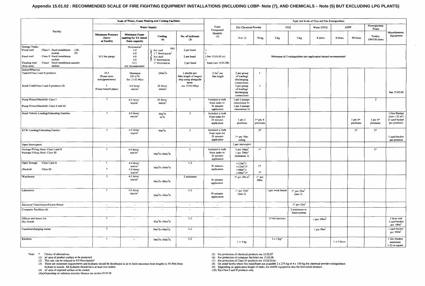
Appendix 15.01.02 : RECOMMENDED SCALE OF FIRE FIGHTING EQUIPMENT INSTALLATIONS (INCLUDING LOBP- Note (7), AND CHEMICALS – Note (5) BUT EXCLUDING LPG PLANTS)

Appendix 15.01.03
PLANNING AND PROVISION OF EXTINGUISHERS
The following extracts from BS 5306 (British Standard 'Code of Practice for Selection - Installation ofMaintenance of Portable Fire Extinguishers'), Part 3 may help selection of correct type, size and numberof extinguishers for different situations. For a more thorough treatment refer to BS 5306, Part 3.
1. INTRODUCTION
The scheme of classification and rating given in BS 5423 (specification for Portable FireExtinguishers) makes it possible to specify the distribution of extinguishers in buildings accordingto extinguishing capability rather than by extinguisher type and size or content.
According to this scheme, extinguishers are marked with numbers and letters indicating therelative maximum size and type of fire they are capable of extinguishing (under the conditionsand procedures set out in BS 5423). For example, an extinguisher marked '8A' is capable ofextinguishing a class A test fire of size 8A, and an extinguisher marked '13A' is capable ofextinguishing a class A test fire of size 13A. Similarly an extinguisher marked '55B' is capable ofextinguishing a class B test fire of size 55B. Extinguishers with both class A and class Bcapability are marked accordingly, e.g. 13A/55B.
1.1. CLASS A FIRES (SOLIDS, WOOD, PAPER MATERIAL)
Class A materials are generally present in all premises and occupancies. The basic scale ofprovision of extinguishers where these are the only primary first aid means of fire defence is that,on each storey, there should be at least two extinguishers sited in suitable positions. The totalclass A rating of all extinguishers on that storey should not be less than 0.065 x floor area ofstorey (in m2), and in no case less than 26A (see note). This minimum requirement correspondsto a floor area of 400 m2. However, in the case of buildings in single occupancy with upper floorarea not exceeding 100 m² the minimum aggregate rating required for these floors is 13A, andthere need not be two extinguishers per floor on the upper floors.
The extinguishers tests of BS 5423 are made under draught-free conditions. Class A fires aremore difficult to extinguish and more liable to re-ignite, outdoors or indoors where there are aircurrents. Under such conditions powder, water or foam extinguishers are recommended.
Note: The assumption is made that a 9 litre (2 gallon) water extinguisher can achieve a 13Arating.
1.1.1 Example - Minimum Provision for Class A Fires
For a single storey building of floor area 1 600 m2 the minimum aggregate class A rating is:
0.065 x 1 600 = 104A (see BS 5306 Part 3)
This aggregate rating can be provided in one of a number of ways. For example:
8 x 13A extinguishers = 104A
(2 x 27A) + (7 x 8A extinguishers) = 110A
4 x 27A extinguishers = 108A
3 x 43A extinguishers = 129A
(1 x 43A) + (5 x 13A extinguishers) = 108A
Note that the travel distance for any point on the floor to the nearest extinguisher should notexceed 30 m. This may mean that extinguishers additional to this minimum should be installed.

1.2. CLASS B FIRES (LIQUIDS AND LIQUEFIABLE SOLIDS)
Table 1 gives recommended minimum ratings for the selection of extinguishers for class B fires.It should be remembered that different types of extinguisher, of the same rating, have differentcharacteristics which, in particular circumstances, may make one type preferable to another.Mass for mass, powders are probably the most effective medium against class B fires but theyare not effective against fires in which part of the fuel surface is shielded from the powderdischarge. Re-ignition of the fuel is possible once the powder discharge ceases; it is not possibleto partially extinguish the fire. This applies also to carbon dioxide and halons where still installed.
Foam is not effective against ' running' fires, but is effective against contained fires where it willprovide semi-permanent protection. With foam it is possible to partially extinguish a fire whichwill not regain full intensity for some time until the foam over the surface is destroyed. Foam canbe applied to liquids in tanks to shield them from ignition from another source, or to prevent theevolution of flammable vapours.
Special types of foam are required for use against water-miscible liquids.
Where both foam and dry powder extinguishers are installed, care should be taken to ensurecompatibility of use.
TABLE 1 : MAXIMUM AREA OF CLASS B FIRE (DEEP LIQUID)FOR WHICHEXTINGUISHERS ARE SUITABLE
Extinguisherrating
Maximum area for threeextinguishers (foamextinguishers only )
Maximum area fortwo extinguisher
Maximum area forone extinguishers
m² m² m²
13B 0.26 0.16 0.09
21B 0.42 0.26 0.14
34B 0.68 0.42 0.23
55B 1.10 0.69 0.37
70B 1.40 0.88 0.47
89B 1.78 1.11 0.59
113B 2.26 1.41 0.75
144B 2.88 1.80 0.96
183B 3.66 2.29 1.22
233B 4.66 2.91 1.55
296B 5.92 3.70 1.97
377B 7.54 4.71 2.51
479B 9.58 6.00 3.19
610B 12.20 7.62 4.07
1.2.1 Grouping of Class B Fire Risks
To determine the minimum recommended provision of suitable extinguishers it is convenient toassess premises in the following manner:
• Each room or enclosure should be considered separately.• Fire risks more than 20 m apart should be considered separately.• Fire risks sited within 20 m of another fire risk should be assessed either as undivided
groups or as divided groups.
Note: Extinguishers should be sited as close as possible to the anticipated point ofoccurrence. It is undesirable to cover dispersed risks with the same extinguisher(s),with consequent excessive travel distances to reach the fire with an extinguisher. Thedistance apart of 0 m has been selected as reasonable in view of the danger of rapidspread inherent in class B fires.

1.2.2 Contained Fires
Single open topped containers: The minimum class B rating of an extinguisher orextinguishers recommended for a single open-topped container of flammable liquid (e.g. mixingvessel, spillage in bunded area) can be read directly, from Table 1. The surface area of thecontainer is used to determine the rating.
Undivided group of containers: Containers less than 2 m apart should be considered as anundivided group, equivalent to a single container. The total surface area of all containers in thegroup is used to determine the recommended rating. The minimum class B rating recommendedcan be read from Table 1 using this value.
Divided group of containers: Containers more than 2 m, but less than 20 m apart, should beconsidered as forming a divided group. The surface area of the largest container (or aggregatesurface area of the largest undivided group) or one-third of the aggregate surface area of all thecontainers in the group, whichever is the greater, is used to determine the recommended rating.The minimum class B rating recommended can be read from Table 1 using this value.
Spillage: The recommended minimum rating of extinguisher to cover spillage of flammableliquid is calculated from the anticipated volume of spillage as follows:
Recommended minimum rating = 10 x volume (in litres) of spillage
The volume of spillage should be assessed according to the particular circumstances. In thecase of non-spillproof movable containers it should be assumed that the whole contents of thelargest moveable container may spill.
Large volume spillage into restricted areas such as bunds, silled rooms and gullies should not beassessed by the formula given in this clause, but should be regarded as a container fire of areaequal to that of the restricted area.
1.2.3 Additional Provision of Extinguishers
It should be borne in mind that the recommendations given in Table 1 are minima and areintended to cover the more common flammable liquids. Where liquids have a low flash point orare especially difficult to extinguish, such as diethyl ether and carbon disulphide, higher ratedextinguishers should be provided. In areas protected by fixed systems, portable extinguishersshould be provided to cover the risk of spillage or fires originating outside the range of the fixedequipment. Similarly, where high rated extinguishers are installed it is advisable to provideadditional low rated extinguishers for use on small fires in preference to the higher ratedextinguishers to reduce contamination, replacement costs, etc. and should be sited close toanticipated point of occurrence. These additional extinguishers should be selected according tothe recommendations given in Table 1.
1.2.4 Examples: Minimum Provision for Class B Fires (Single Containers)
1.2.4.1 A single tank of surface area 1.0 m² is situated in a room. The recommended minimum rating isfound from Table 1 as follows:
• If only one extinguisher is to be installed, 183B (from columns 4 and 1).• If two extinguishers are to be installed, 89B each (from columns 3 and 1).• If three extinguishers (foam only) are to be installed, 55B each (from columns 2 and1).
1.2.4.2 A vessel containing a maximum of 200 litres of flammable liquid is positioned within a bund 1.3 mx 1.9 m of suitable depth
The recommended minimum rating is found from Table 1 as follows, using the area of the bund1.3 x 1.9 = 2.47 m²:
• If only one extinguisher is to be installed, 377B (from columns 4 and 1).• If two extinguishers are to be installed, 233B each (from columns 3 and 1).• If three extinguishers (foam only) are to be installed, 144B each (from columns 2 and 1).
1.3. MIXED RATINGS
Where both class A and class B materials are present in the same area extinguishers should beprovided to meet both recommendations. The installation of a single type of extinguisher(s), withboth class A and class B ratings is recommended in preference to two types, one class A theother class B, taking note of the limitations of the various types.

1.4. RATING OF EXTINGUISHERS MANUFACTURED IN ACCORDANCE WITH OLD BRITISHSTANDARDS
Such extinguishers which comply with obsolete standards may be regarded as having ratingsnot higher than those given below.
Extinguisher type Rating (max)
9 litre water extinguisher 13A
9 litre foam extinguisher 34B
1.5 kg halon 21B
2 kg carbon dioxide 21B
4.5 kg carbon dioxide 34B
3 kg powder 55B
9 kg powder 144B
14 kg powder 233B
Sizes not listed may be regarded as having ratings in general accordance with these values.
Appendix 15.01.04
1. LIMITING OF HALON EMISSIONS
Halons are regarded as ozone damaging chemicals and many countries are now imposingrestrictions on their use. The following is recommended for all PETRONAS marketingoperations.
The following approaches should be taken to reduce the emission of Halon 1301 and Halon1211 into the atmosphere:
1.1. EXISTING SYSTEMS
• Stop all release of Halon during training (e.g. release from portable extinguishers); use analternative such as CO2.
• Generally phase out mobile and portable Halon 1211 extinguishers (replacing bywater/foam/CO2/dry powder as appropriate).
• Reduce any systems which are oversized (e.g. total room flooding where cabinet floodingwould suffice, or enclosures which could be subdivided).
• Reinforce maintenance procedures to detect leakage from existing systems.• Test fixed Halon systems without release of Halon 1301 or 1211 (this may require some
modification of existing systems).• Immediately put all automatic Halon 1211 and 1301 total flooding systems at normally
manned locations on manual release, to avoid spurious trips and to give the possibility ofmanual intervention using less (or alternative) extinguishing media. Detection systems, e.g.heat or smoke detectors, should be realistically tested for rapid response to the specifictypes of fire which may be expected, to minimise the additional damage which could resultfrom this slower approach.
• Generally remove the Halon 1211 bottles from floating roof tank systems, but ensureadequate detection and alarm. Install fixed or semi-fixed dry riser foam systems on allfloating roof tanks which do not already have them (for continuous fire attack). Floating rooftanks in areas where there is a high risk of lightning strikes may require specialconsideration.
• Generally phase out fixed Halon systems at times of major overhaul. For exceptionalcircumstances, where Halon is still considered to be essential, total flooding systems shouldbe on manual release only, operated as a last defence, and should be refilled with safedisposal of the Halon, as soon as suitable alternatives become available.
1.2. NEW PROJECTS
• Do not install Halon 1211 mobile and portable extinguishers.• Do not install fixed Halon systems (possible alternative for unmanned rooms containing
major electric/electronic equipment is to use water sprinklers in the room and ceiling void,and CO2 in underfloor areas, after electrical isolation). Protection of unmanned rooms shouldbe based upon manual intervention, with automatic detection and alarm, as appropriate.
For further information or advice please contact PETRONAS.

Appendix 15.01.05
1. FIXED COOLING FOR VERTICAL TANKS
1.1 APPLICATION RATE
For newly constructed tanks which require fixed cooling a minimum water application rate of1.71/min/m² for the roof and 171/m length of shell circumference should be used (refer Section15.02.01).
For existing tanks, upgrading of fixed cooling facilities should also be considered. This will bedependent upon:
• Actual tank spacings and general layout.• Speed and reliability of back-up fire fighting support.• Strategic importance of the storage facility/possibility of arranging suitable exchange product
liftings.
1.2. TANK SEGMENT COOLING
Selective cooling of segments of the total circumference of large tanks may be achieved byinstalling two (or more) separate spray ring headers at the top of the tank Shell. Separate waterdelivery lines and valves will also be required. This arrangement will help to limit the requiredcapacity of fire pumps and hydrant lines, and will also reduce the possibility of overloading ofbund drainage facilities in the event of a major fire.
2. SPRAY RINGS
Tank cooling should be achieved using stainless steel spray nozzles located on one or moretank top headers as well as on the tank shell. The minimum spray orifice size should be 6 mm toavoid blockage. At this diameter, and at an application rate of 17 litre/m circumference,pressures of around 2.5 to 3.0 bar ex-hydrant will be required. Therefore a pressure reducingdevice (possibly a length of pipe of restricted diameter) will be needed.
Hot dip galvanized mild steel pipe is recommended for the spray system and all connectionsshould be flanged, which avoids the potential for rusting if screwed connections are used.
A bucket type filter should be installed at each supply manifold with a stainless steel filterelement with openings of 3 to 4 mm.
Each tank should have a spray ring header installed at the top of the tank shell with nozzleslocated up to 450 mm out from the shell plates. Additionally one or more ring headers are to beinstalled on the roof, as follows:
Tank diameter (m) Number of roof headers
Up to 17.5 1
17.5 to 36 2
36 to 52 3
Numbers of spray nozzles on headers will depend on their flow rates and spray patterncharacteristics. Including run-down of water from roof headers, all parts of the tank surfaceshould receive 1.7 litres/min/m².
Tanks located 40 m or more from other tankage, pumphouses, loading facilities, etc. do notrequire fixed cooling arrangements.
2.1. TESTING OF WATER SPRAY SYSTEMS
A major problem associated with water spray systems is blockage of spray jets. Some of themain causes of these blockages are known to be debris left inside the pipes during installationand repairs, gravel and debris carried by the water and corrosion products which originate in thefeed lines. The pipes used in water spray systems are hot-dip galvanised and, to preserve theircorrosion resistance properties, should only be connected by flanges. This requirement is,however, often neglected. Pipes are cut and welded and, as a result, complete layers ofzinc/zinc oxide become detached from the inner walls and form blockages in the system. SeeFigure 15.01.31 for Typical Dry Riser showing surface and flushing test connections.
The main cause of spray systems failure is, however, the gradual build-up of silt which, in time,hardens and then breaks into lumps large enough to block the nozzle. Frequent flushing of thelines helps to keep them clear but even well maintained systems can suffer blockages if thedesign of the system allows sediments to accumulate at critical points. The sediments usuallyenter the system through small, undetected leaks but the ingress of silt and small size gravelduring water tests is thought to aggravate the situation. Blockages are often found where thereare reductions in pipe diameter and in systems which utilise small bore (4 to 5 mm diameternozzles).
It is recommended that the dry riser and spray system should be smoke tested every year andfully water tested every three years. The smoke being hydrocarbon generated has a corrosioninhibiting effect in the dry riser and spray rings.
Operation staff are not keen to test water spray systems with water for a number of reasons. Inthe first place, flooding an installation or depot with water grossly interferes with its normalfunctions. Even then it is considered a nuisance since all other work must be stopped and alldelicate equipment must be protected. Full flow tests require large volumes of water which, insome installations or depots it means the introduction of back- up sea or brackish water into theservice-water facility which therefore necessitates fresh water flushing. This can acceleratecorrosion and wear in the system which, in the long term, increases the probability of blockagesby corrosion products. Poorly drained sections will fill with water during a test and the standingwater may subsequently freeze and block a complete section of the system. This problem maynot exist in a well designed system but 'dead legs' can be introduced at any time when aninstallation undergoes repairs or modifications.
In some installations or depots the service water is dirty and will deposit silt and debris in lowflow sections of the network. When the demand grows, as when spray systems are water tested,these may be carried by the increased flow and cause blockages. It is claimed that the watercoming out of the nozzles leaves dirty stains on painted tank walls, others admit that the wholeoperation is alien to the normal functions of the plant and, consequently, not very popular. Theidea of being able to dry-test water spray systems appeals to those responsible for theirmaintenance. Dry tests can indeed be very useful especially where water tests are genuinelyimpossible or difficult to conduct. However, in most cases they can only be considered as a toolwhich may complement wet tests, not replace them.
The latest development in testing spray systems by using smoke generating equipmentproduced by 'Acettain Ltd' of London, and is termed the 'PRO-MIST' package. Briefly thepackage comprises a smoke generator together with an electric motor driven for using mainscurrent and when coupled to a connection in the spray piping can direct smoke over a distanceof 150 metres to enable testing and detecting blocked jets in the system. The time taken fromstart up of the equipment until smoke reaches the jets is about 30 minutes.
The overall dimensions of the equipment is 850 x 50 x 350 mm, weighing 40 kilos. It is notintrinsically safe and must be used accordingly. It is recommended only suitably trained andsupervised personnel should use this apparatus. Further details are obtainable fromPETRONAS.
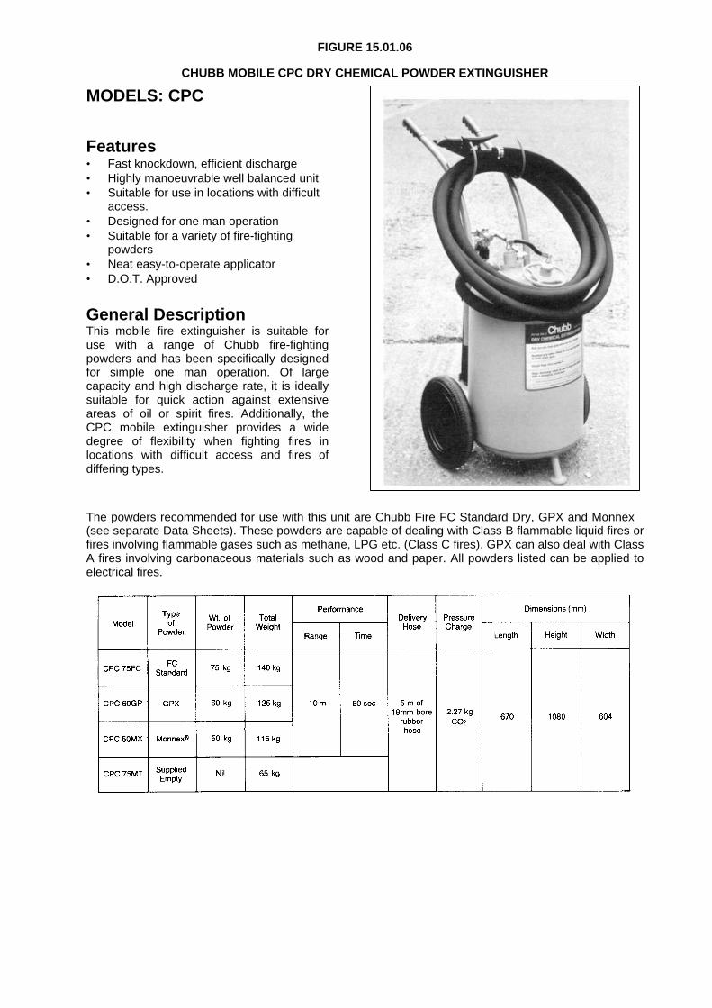
FIGURE 15.01.06
CHUBB MOBILE CPC DRY CHEMICAL POWDER EXTINGUISHER
MODELS: CPC
Features• Fast knockdown, efficient discharge• Highly manoeuvrable well balanced unit• Suitable for use in locations with difficult
access.• Designed for one man operation• Suitable for a variety of fire-fighting
powders• Neat easy-to-operate applicator• D.O.T. Approved
General DescriptionThis mobile fire extinguisher is suitable foruse with a range of Chubb fire-fightingpowders and has been specifically designedfor simple one man operation. Of largecapacity and high discharge rate, it is ideallysuitable for quick action against extensiveareas of oil or spirit fires. Additionally, theCPC mobile extinguisher provides a widedegree of flexibility when fighting fires inlocations with difficult access and fires ofdiffering types.
The powders recommended for use with this unit are Chubb Fire FC Standard Dry, GPX and Monnex(see separate Data Sheets). These powders are capable of dealing with Class B flammable liquid fires orfires involving flammable gases such as methane, LPG etc. (Class C fires). GPX can also deal with ClassA fires involving carbonaceous materials such as wood and paper. All powders listed can be applied toelectrical fires.

FIGURE 15.01.07
CHUBB FL22 MOBILE FOAM LIQUID PROPORTIONER UNIT CHUBB MOBILE FOAM UNITS
Hosemaster Hosemajor
Total flow 451/min at 7 bar 451/min at 3 bar(10 gpm at 100 psi) (10 gpm at 43 psi)
Operating pressure 3 to 10 bar 2.0 to 3.4 barRange (45 to 150 psi) (30 to 52 psi)Foam Concentrate All fire fighting Hazmat 1 & 2
concentrates Masterfoam (A)Hex (S)
Foam ConcentrateCapacity 11 litres 11 litresDischarge time 6% 4 minutes 4 minutesDischarge time 3% 8 minutes 8 minutesCoupling 3/4"BSPF 3/4"BSPFFinish Cream Dark BlueWeightEmpty 5.6 kg 5.6 kgFull 17.5 kg 17.5 kg
Capacity: 100 litres (22 UK gal) foam compound (3% or 6%)Water supply required: 225 litres/minOperating pressure: 3-10 barsOperating time: 3% compound - 14 minutes
6% compound - 7 minutes
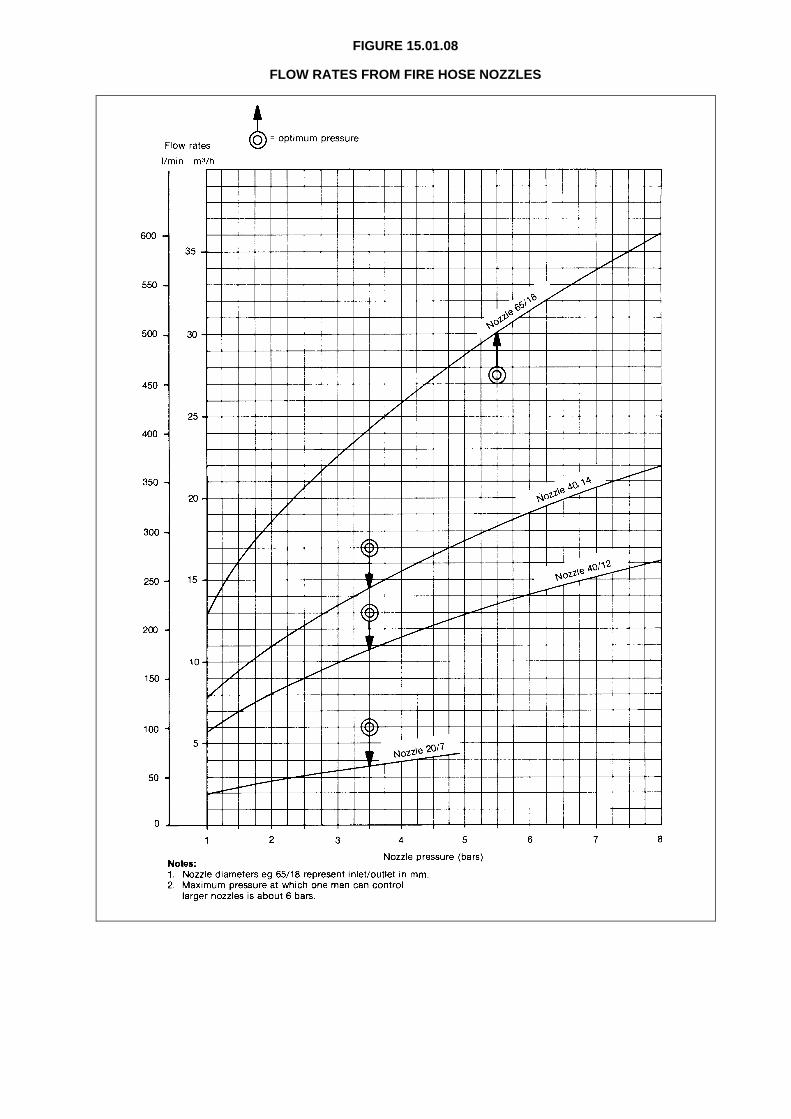
FIGURE 15.01.08
FLOW RATES FROM FIRE HOSE NOZZLES

FIGURE 15.01.09
PRESSURE LOSS IN FIRE HOSES

FIGURE 15.01.10
HYDRANT-FED FIRE-FIGHTING EQUIPMENT
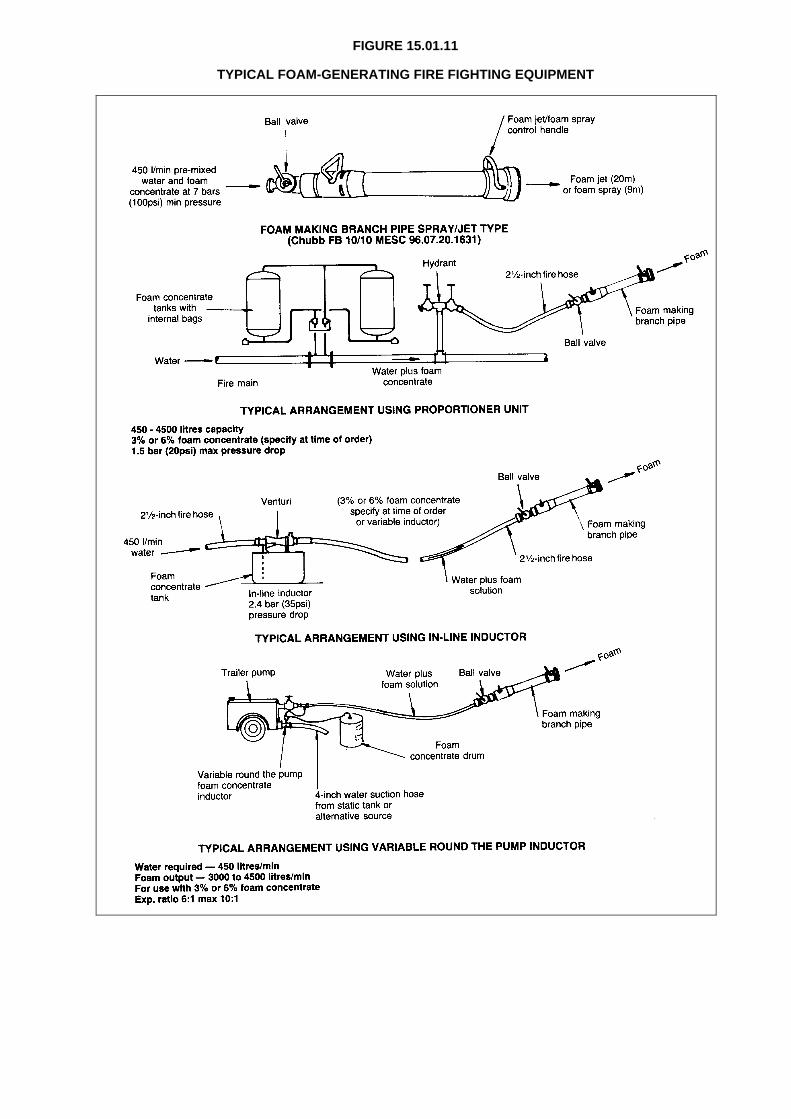
FIGURE 15.01.11
TYPICAL FOAM-GENERATING FIRE FIGHTING EQUIPMENT

FIGURE 15.01.12
TYPICAL FOAM CONCENTRATE INDUCTION
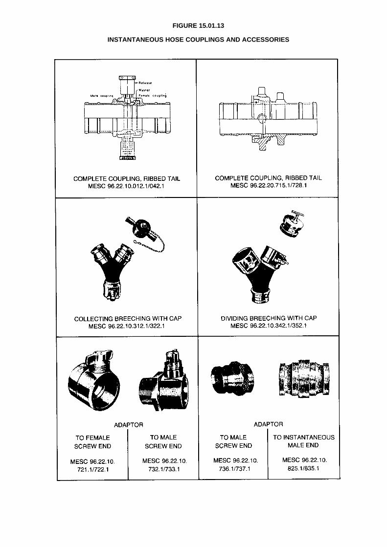
FIGURE 15.01.13
INSTANTANEOUS HOSE COUPLINGS AND ACCESSORIES

FIGURE 15.01.14
TYPICAL MECHANICAL FOAM GENERATORS

FIGURE 15.01.15 CHUBB ‘JET-MASTER’ PORTABLE MECHANICAL FOAM/WATER MONITOR
Foam improver/nozzlesection in which foamof correct consistencyis formed and expelledas high-velocity ropejet. For water sprayonly, this section isremoved
Main body comprisestwo sections joined byquick action thread
Two legs, independentlyadjusted and lockable,support monitor atelevations between 40°to 70°
Carrying handle
Connection foraluminium foamcompound pick-uptube/hose assemblyor for 1½-inch hosefrom wheeled foamliquid tank
Swept-elbowconnector fitted withtwo 2½-inchinstantaneous malecouplings. (Othercouplings can befitted)
Swivelling baseplate allowsalteration ofelevation while theunit is operating
WATER FLOW : 1600 litres/min at 10.5 barsFOAM COMPOUND 3% or 6% by calibration
JET LENGTH : 40m at 10.5 barsJET HEIGHT :
- FOAM : 12m at 6.7 bars 23m at 10.5 bars
- WATER : 30m
Easily observedpressure gauge,recessed forprotection
Foam generatorsection whichcombines water,foam liquid and air
Total weight 34 kg (74.5 lb)

FIGURE 15.01.16
CHUBB RANGE OF HIGH BACK PRESSURE FOAM MAKERS
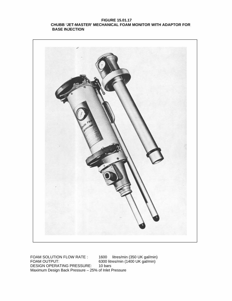
FIGURE 15.01.17CHUBB ‘JET-MASTER’ MECHANICAL FOAM MONITOR WITH ADAPTOR FOR
BASE INJECTION
FOAM SOLUTION FLOW RATE : 1600 litres/min (350 UK gal/min)FOAM OUTPUT: 6300 litres/min (1400 UK gal/min)DESIGN OPERATING PRESSURE: 10 barsMaximum Design Back Pressure – 25% of Inlet Pressure

FIGURE 15.01.18
ANGUS VARIABLE FOAM INDUCTOR
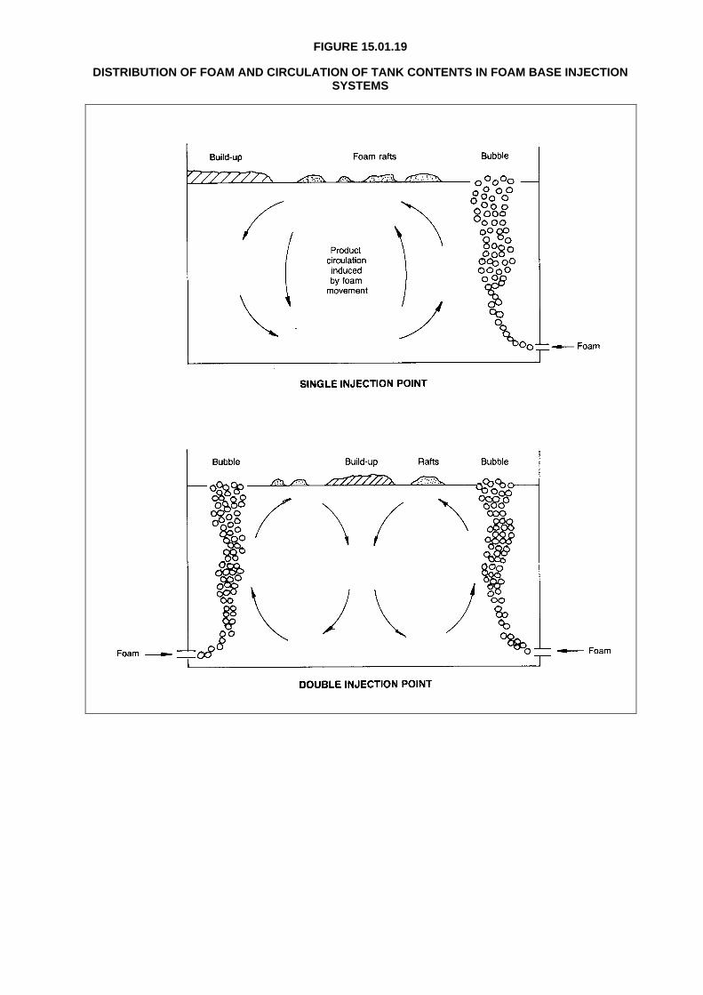
FIGURE 15.01.19
DISTRIBUTION OF FOAM AND CIRCULATION OF TANK CONTENTS IN FOAM BASE INJECTIONSYSTEMS
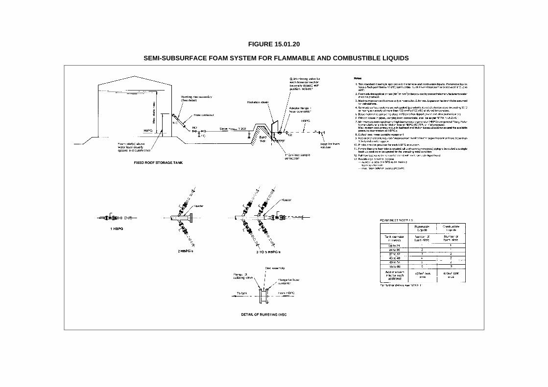
FIGURE 15.01.20
SEMI-SUBSURFACE FOAM SYSTEM FOR FLAMMABLE AND COMBUSTIBLE LIQUIDS
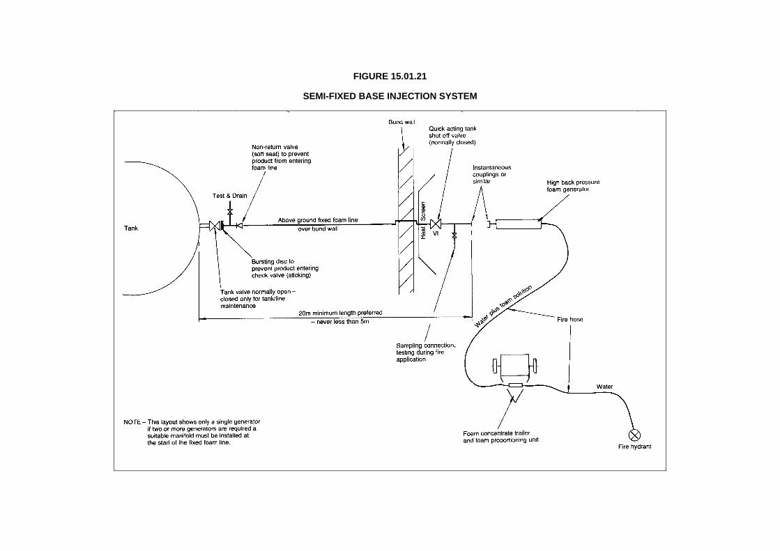
FIGURE 15.01.21
SEMI-FIXED BASE INJECTION SYSTEM
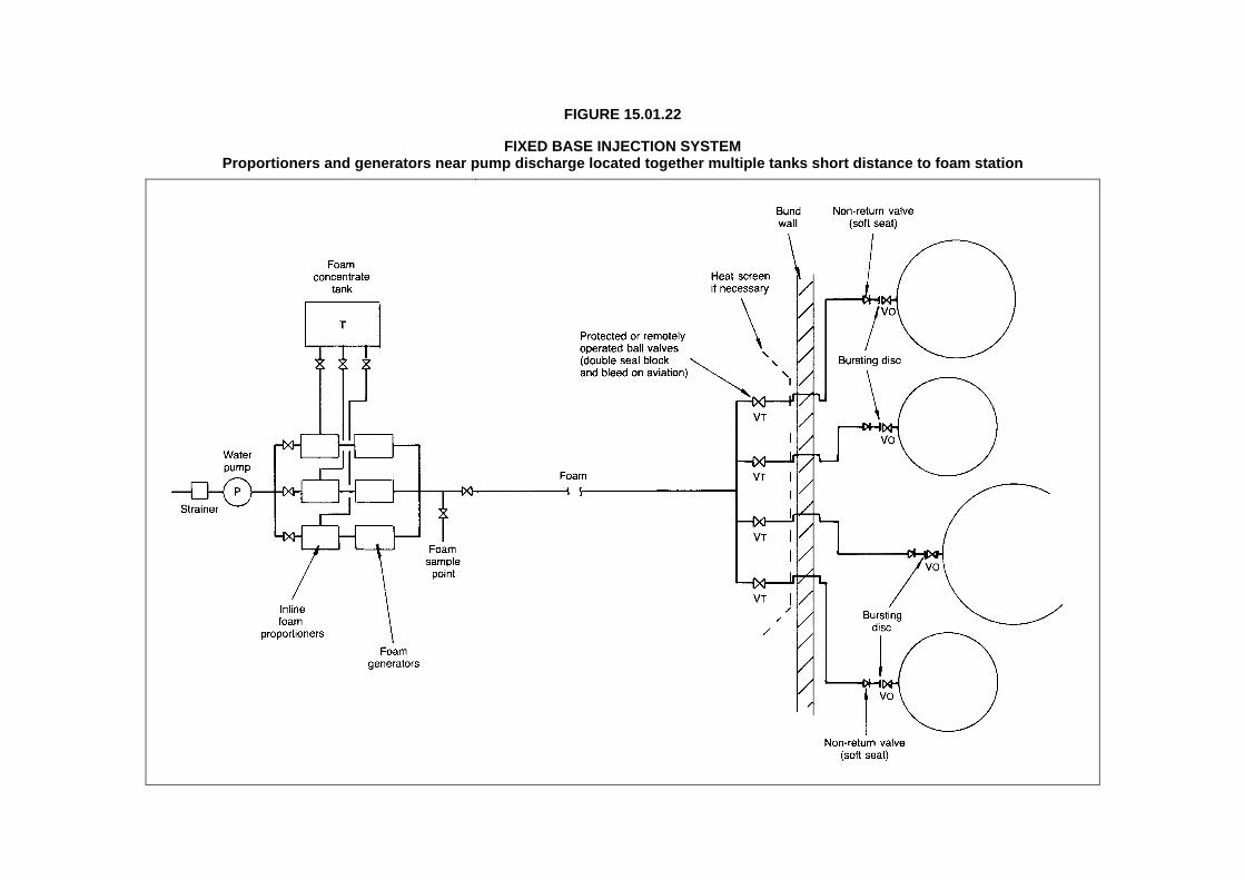
FIGURE 15.01.22
FIXED BASE INJECTION SYSTEMProportioners and generators near pump discharge located together multiple tanks short distance to foam station

FIGURE 15.01.23
FIXED BASE INJECTIONProportioners and generators near pump discharge

FIGURE 15.01.24
FIXED BASE INJECTION SYSTEMGenerators separated for proportioner – multiple tank separate foam lines to each tank

FIGURE 15.01.25
ANGUS FIRE ARMOUR HIGH-BACK-PRESSURE FOAM GENERATOR (SERIES 2)
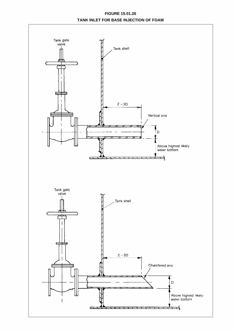
FIGURE 15.01.26
TANK INLET FOR BASE INJECTION OF FOAM
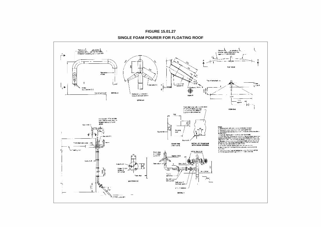
FIGURE 15.01.27
SINGLE FOAM POURER FOR FLOATING ROOF

FIGURE 15.01.28
FOAM POURERS FOR FLOATING ROOF TANKS
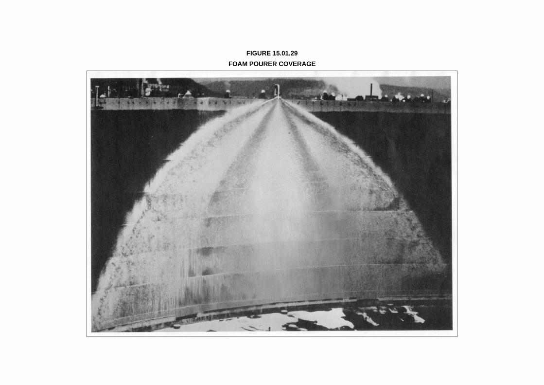
FIGURE 15.01.29
FOAM POURER COVERAGE

FIGURE 15.01.30
N2 UNIT FOR ‘POLY-FLO’ LINE DETECTION (Manufacturer – Saval Kronen0burg B.V. Prinsenbeck –Holland)

FIGURE 15.01.31
TYPICAL DRY RISER SHOWINGS SMOKE AND FLUSHING TEST CONNECTIONS

Appendix 15.02.01
SUB-SURFACE FOAM INJECTION - DESIGN AND EQUIPMENT - PROTECTION
1) GENERAL DESCRIPTION
The required capacity of a base injection system for fixed roof tanks is based on the minimumfoam solution (water plus foam compound but not aspirated) flow rate required to extinguisha storage tank fire. The recommended minimum rates, based on BS 5306 - Section 6.1 are asfollows:
• Class I and II products:
- 4.0 litres/minute/m² of product surface to be protected.
Sufficient foam compound and water should be available to permit continuous operationat this application rate for a period of 45 minutes.
• Class III products (not normally required):
Notwithstanding the above, gas oil tanks located adjacent to Class I storage, should betreated as Class I tankage to facilitate possible product changes in the future.
- Black oils - base injection not suitable.
The design of a sub-surface systems involves a sequence of steps as follows:
(i) Calculating the minimum acceptable foam solution flow rate. When more than one tankis to be protected by the same system, the design flow rate is determined by the tankrequiring the highest flow rate.
(ii) Selecting the number, size and distribution of foam generators plus the general layout ofwater, foam solution and finished foam pipelines. Depending on the tank farm layout aswell as the location and orientation of water supply, the combination and grouping ofgenerators (and their related inductors) may vary from:(a) A single battery of generators to supply all needs via a foam distribution
manifold.(b) A number of separate batteries of generators strategically located to serve
different groups of tanks.The decision between semi-fixed and fixed systems will also have to be made at thispoint in the calculation.
(iii) Selecting the number of foam inlets for each storage tank, which is governed by thediameter of the tank in accordance with the table given in Section 15.01.03 (c iii). Analternative arrangement using a single tank inlet and multiple foam outlet points is shownin Figure 15.01.28.
(iv) Estimating the foam inlet diameters. Foam inlets must be sized so that the velocity offoam entering the tank is not greater than 3.0 m/second for volatile products (flash-pointless than 21 °C) or 6.0 m/second for non-volatile products (flash-point equal to or greaterthan 21 °C). The correct attitude of the inlets is horizontal (not upwards or downwards); a45° chamfer is acceptable, see Figure15.01.26.Foam velocities may be greater in the pipelines further upstream of the tank inlet (whichpermits the use of smaller pipelines) but pipelines must be increased to the correct inletdiameter at a distance of not less than 20 times the pipe diameter from the inlet to thetank. At no point should the foam velocity exceed 9.0 m/second in this section ofpipeline. Further upstream the velocity is not critical but should not be too low so as toavoid drainage of water.The inlet diameters estimated at this stage will have to be checked at a later stage in thedesign depending on the ultimate hydraulics of the system.

(v) Calculating systems pressure losses so as to derive the finished foam pipeline diametersdownstream of the foam generators. This part of the design is governed by a number ofparameters:- The design of foam generators is normally such that the maximum back pressure
downstream of the generator outlets (caused by pipeline losses, elevationdifferences and static head of product in the tank) must not exceed 40 per cent of theinlet pressure to the foam generators (old type generators 25 per cent). This is thestarting point of the hydraulics design and in situations with high tanks (i.e. highstatic head of product) and high foam flow rate requirements, can result insubstantial pressure requirements. For this reason since pipeline pressure losses forwater or foam solution are much lower than for finished foam, a guiding principle is tominimise the length of finished (aspirated) foam lines by positioning the foamgenerators as far downstream as practically possible so as to limit the distancefinished foam has to be pumped before it enters the storage tank.
- Foam generator inlet pressure requirements vary from 7 to 10 bar depending onmake. Higher pressures can be used to give higher throughputs and/or to meet highdownstream back pressures.
- To allow full development of finished foam properties a foam line length of preferably20 m is required before entering the tank, but 5 m is an absolute minimum withoutsignificant foam deterioration.
(vi) Estimating the inlet pressures to the foam generators (i.e. three to four times the outletback pressures derived from (v) above), thence calculating the foam solution pipelinesized between the pump discharge and the generator inlets (including all pressure lossessustained through the foam compound inductors, proportioners or other units).
(vii) Estimating the volume of foam concentrate, water flow rate and water volume needed toprovide base injection operation at the recommended application rate for a period of 45minutes (or 30 minutes for Class III).
From the above, the sub-surface injection system for one or more tanks can be calculated inisolation from the requirements for the rest of the fire-fighting system.Section C below describes the points to be considered to produce an overall tank farm fire-fighting protection system.
2) DESIGN NOTES
(i) Foam pipelines should, whenever possible, run outside the bund area so as to be lessexposed to fire. This may lead to longer lines which will add to pipeline friction losses.Where a foam line has to run inside the bund area flanges should be eliminated orminimised.
(ii) Testing - once a sub-surface injection system has been installed (or changed orextended) it has to be tested in order to prove the equipment as well as to trainpersonnel in its operation. This is straightforward if the tank is still empty and the injectedfoam can be removed from the tank. If, however, the tank contains product, a perfectlyadequate test can be carried out if a full bore foam outlet/sample point with a backpressure to simulate a full tank is installed in the foam line upstream of the tank valve.
The sample points do not have to be close to the storage tanks but may be moreconveniently located near the foam generators subject only to the 20 m minimumdistance necessary to permit full development of the foam properties. This will minimiseconsumption of foam compound during tests and fire practices, and will also facilitateflushing out the lines after such tests. A minimum slope of 1/240 with suitable drainageoutlets will facilitate flushing and draining foam lines after testing or usage.
Subsequently, periodic testing (during fire drills) is recommended plus routinedismantling and inspection (inside and outside) of equipment and quality testing of foamcompound.
(iii) Quick-action valves - all valves at the tank selection manifold should be quick-action(ball) valves. The size of the ball valves can be reduced to limit cost but to no less than50 per cent of the pipeline cross-sectional area. In such a case however, the additionalpressure lost through the valve must be allowed for in the back pressure calculations.
The non-return valves should preferably be soft seated (but not spring-loaded). Acceptedmaterials for the soft seat are nitrile rubber, Viton and Buna-N but not Neoprene. In theevent that product passes the non-return valve and fills the line from the tank to thegenerator manifold, the aspirated foam is able to push the product back to the tankwithout significant deterioration. If soft seated non-return valves are not available,conventional non-return valves can be installed.

(iv) A special bursting disk with suitable burst pressure should be used between the foamgenerator outlet and the non-return valve. This is to prevent product flow into the foammaking system in case of non-return valve leakage. Conversely it presents water leakingfrom the foam system into water sensitive products such as aviation fuels.
(v) As mentioned in 15.01.07(d) sufficient foam compound must be available or immediatelyaccessible before injection operation begins. One way to minimise total stocks or foamcompound held at any plant, is to keep part of the total requirement in a small bulk tanksuitably located for sub surface injection purposes. The balance can then be stored ineasily movable containers ready to be carried to any part of the site when needed. Forexample, if the sub-surface injection requirement is 2.5 m3 of compound, and this isestimated to be more than enough for any other possible fire, then 1.5 m3 could bestored in a small tank or trailer ready for immediate use in the injection system, and theremaining 1 m3 kept in containers at the most strategic location for any other fire. Theemergency fire plan should then be arranged so that should a tank fire occur, sub-surface injection can start drawing on the 1.5 m3 supply of compound. Previouslydetailed personnel would take the foam containers from the 1 m3 store to the bulk tankready for decanting as the initial supply is consumed. If a fire occurs elsewhere, theportable containers can be taken to the site of that fire for use with the normal hoses andfoam making equipment; if any further stocks of foam compound are needed these canbe drawn from the compound tank.
To minimise foam concentrate deterioration, the tank should be fitted with an expansiondome on top and the level of maintained within the dome. To protect the tank againstinternal corrosion the tank should be lined with bitumen or an 'EPIKOTE' resin basedpaint or non metallic/glass fibre reinforced polyester tank.
(vi) The principle mentioned in Design Notes (v) above of converting foam solution intoaspirated (finished) foam at the latest possible position in the supply line will help limitpressure losses/reduce pipe diameters. Against this saving will have to be offset thepossible need for additional generators because rather than a single battery ofgenerators to cover all needs, locating generators further downstream in the system maymean having to install more than one small battery of generators resulting perhaps in agreater total number of generators required. The relative economics of this must, ofcourse, be assessed. Such a situation would probably not occur with a semi-fixedsystem which depends on a common store of generators which are taken to whichever isthe appropriate foam inlet point at the time of the fire.
(vii) Foam/foam solution distribution systems
Depending on the number of tanks to be protected, as well as the size and layout of thesite, various designs of distribution system can be employed as shown in Figure15.01.21 to 15.01.24 inclusive, and described below.
1) Fixed sub-surface injection system where tanks are only a short distancefrom fire pump/water supply permitting the foam station (foam compound tank,inductor(s), generator(s), etc.) to be positioned together near the pumpdischarge.
(a) This layout (see Figure 15.01.23) is appropriate for single tank protection,and shows how the product inlet may be used as one of the foam inlets.As the tank valves (Vo) must be kept open, a second valve (VT) (orbursting disc with gate valve to protect it when sampling foam) acts tocontain any product that may pass the non-return valve in the foam lines.Valve (Vp) is to prevent backflow of foam in product line and will normallybe closed.
(b) This layout (see Figure 15.01.24) is for multiple tank protection, where thefoam station is only a short distance from the tank farm and pressurelosses are low enough to permit foam generation at the foam station closeto the pump. As tank valves Vo remain open, valves VT outside the bundmust either be quickly accessible (fire screen plus rapid access) or beremotely operable (reliable power) by a protected system.

2) Fixed sub-surface injection system where for distance and/or pressure dropreasons the foam generators are separated from inductor/proportioner units.
(a) This layout (see top tank Figure 15.01.24) is appropriate for single tankprotection. As the tank valve (Vo) is kept open, a bursting disc is all that isrequired outside the bund. A manual valve would not be suitable becauseof the time taken for someone to get to it and open it, but a remotely-operated valve could be used provided that there is a reliable powersupply.
Foam sampling is best done by connecting a generator at the solutionoutlets shown. To sample downstream of the generators entails filling thewhole pipeline with solution which is both costly and would necessitate alaborious draining and flushing operation afterwards.
(b) This layout (see Figure 15.01.24) is for multiple tank protection withseparate lines to each tank. A foam proportioner may be considered heresince it will automatically induce the correct rate of foam concentratedepending on which foam control valve (Vo) is opened, and in addition hasa much lower pressure drop compared with inductors. As this systempermits manual control it is ideal where power supply (for remote valveoperation) is unreliable. For foam sampling see the comments given in2(a) above.
(c) An alternative layout is to run a single foam solution line from thedischarge side of the proportioner to a manifold positioned immediatelyupstream of the generators. In this case the control valves would have tobe remotely operated, which means a reliable and protected power supplyis essential. Bursting discs are necessary to contain product as tankvalves are kept open. The same comment as in 2(a) above covers foamsampling.
3) Semi-fixed sub-surface injection system. A typical layout is shown (Figure15.01.21) in which the foam inductor and generator are brought to the foam inletpoint outside the tank bund and connected to the water supply by hoses. Foamsampling can be done in either way (1 or 2 above) depending on pipe lengths,layout, etc.
(viii) Equipment - all pipelines, valves and other standard fittings should be in accordance withthe specification for normal installation operations given in the Installations and DepotsManual, 06.01.04. In addition, the following items of equipment have been developedespecially for sub-surface injection:
(a) High back-pressure generators - these are required to produce foam with suitableproperties for sub-surface injection; expansion two to four and a 25 per centdrainage time of 90 to 180 seconds. Models are available from differentmanufacturers for a range of foam solution flow rates or between about 50 and 2250 litres/minute (10 and 500 UK gallons/minute) and which operate at inletpressures ranging from 7 to 10 bar; examples are shown in Figure 15.01.16,15.01.17 and 15.01.25.
One supplier has produced an adaptor, see Figure 15.01.17 for use with theexisting foam monitor shown in Figure 15.01.15.
(b) Foam compound inductors and proportioners - most in-line inductors working onthe venturi principle with a minimum induction rate of 3 per cent can be used. Oneof the models available is illustrated in Figure 15.01.18. The inductor unit suffersone major drawback in that pressure lost through it equals one-third of its inletpressure. Thus to feed high back-pressure generators which require minimum inletpressures of 7.0 bar, the inlet pressures to the inductor must be 10.5 bar. Thesepressure levels may be tolerable for relatively small or simple applications whereback-pressures downstream of the generators can be kept to reasonable levels (orfor non-subsurface injection applications) but for larger systems at higher pressurelevels generally an alternative such as a variable-flow proportioner may beconsidered as it has a considerably lower pressure drop and inducts foamcompound at a rate directly proportional to the water flow rate through it. However,the relative economics must be assessed before the choice is made.

3) TOTAL TANK FARM PROTECTION
Sections A and B have discussed the design of a sub-surface foam injection system for storagetanks in isolation, and have given a number of related design factors that must be taken intoaccount.
In order to complete the protection of a tank farm two further aspects must be considered:
(i) Supplementary protection
Supplementary protection should be provided either to extinguish small ground fireswithin the bund or, elsewhere, or to enable extra cooling water to be directed at storagetanks if needed. For this, branch pipes with a water or foam solution flow rate ofapproximately 450 litres/minute (100 UK gallons/minute) plus supplementary foamcompound should be provided as shown in the following table:
Diameter of largest Number of Minimum operating
tank in m branch pipes time in minutes
Up to 10 1 10
10 to 20 1 20
20 to 30 2 20
30 to 39 2 30
Over 39 3 30
(ii) Water for cooling tanks and/or LPG vessels (see 15.03.02 or LPG Manual).
The overall combination therefore of:
• The requirements for sub-surface foam injection,• The supplementary protection needed,• The tank cooling by spray rings (or sprinklers),
will result in a total demand for water flow rate and pressure necessary in the event of astorage tank fire. From this the pressure and flow specifications of the fire water pump(s)can be derived. A major practical element in the design of the system is the actualmethod of sharing, the total water supply between sub-surface foam injection,supplementary protection and tanks cooling.
The first requirement is a centrifugal pump whose flow/head curve is reasonably flatparticularly on the low head side of the design operating point. This will minimisevariation in discharge pressure irrespective of the actual total demand. The followingfactors must next be considered:
(a) Cooling water for spray rings (or sprinklers) for product storage tanks.
For very simple tank farms where the cooling water systems may comprise separatelines running from the pump discharge manifold to each tank, it may be possible to sizethe lines such that each tank receives close to the correct flow rate of water.
However, for most systems operating from a ring main (complete with hydrants andbase injection systems) the hydraulics are too complicated for such treatment. Therecommended solution in such cases is to fit a simple but appropriate pressure gaugedownstream of the cooling water offtake valve to each tank. From initial trials for eachtank cooling line, the degree of valve opening that will give the correct cooling water flowrate can be determined. The corresponding pressure reading can then be taken andmarked on the face of the gauge so that in future the correct flow rate to each tank canbe set simply by adjusting each cooling line valve until the gauge reads the pre-determined pressure. During actual usage, the setting of these valves will have to beback-checked and re-adjusted both at the time of initial opening to start the cooling, andsubsequently at intervals since fluctuations in water demand will cause some pressurevariations during the fire-fighting activity.
(b) Supplementary protection
These requirements are not so critical in terms of exact flow rates. If foam for attackingground spill fires or additional water for cooling purposes are required, these can beprovided by opening the necessary hydrant valve on the water ring main and the pumpdischarge will automatically adjust. If supplementary protection is not required then themains capacity will remain available for other purposes.

(c) Sub-surface injection
Depending on which tank is on fire the demand for foam will vary from the maximum(design) flow rate to something less. The actual foam flow will be controlled on site byopening the requisite number of foam generators for the tank concerned. Thegenerators are largely self-governing in that at design pressure they will pass the designflow rate but at higher pressures they will pass more in accordance with normalhydraulic flow criteria, i.e. that velocity is proportional to the square root of the pressure.
If, therefore, a small tank is on fire, requiring only a proportion of the total number offoam generators to be opened, this will present to the pump a back pressure somewhathigher than its design. The pump will automatically adjust to these flow conditions whichwill result in an increased inlet pressure and flow rate through each generator such thatthe inlet velocity to the tanks may exceed the allowed limit (3 m/second or 6 m/second).If the pump (centrifugal) operating curve is flat enough such that the increase inpressure between the design point and the actual operating point is small enough, thenthe flow rate increase will also be relatively low and would not be expected to exceedthe allowed limits significantly.
To illustrate - if, for example, only opening 2 out of 3 available generators causes apump discharge pressure increase of say 15 per cent above pump design point, thiswould lead to an increased flow rate, per generator, equal to the square root of 1.15 percent which equals 1.07 per cent. Thus the flow velocity would be 7 per cent higher andwhether this increase causes the tank inlet velocity to exceed the permitted limits canthence be checked during the design phase.
In the same way the various downstream flow conditions (caused by opening all relevantcombinations of foam generators) must be re-checked against the operating curve ofany existing pump or new pump under consideration.
Note: Another situation which does not have any adverse effect is when theproduct level in a tank is particularly low at the time of a fire. In such a case theback pressure downstream of the generator is reduced and it might be thoughtthis would lead to an increase in flow rate and consequent tank inlet velocityproblems. This does not occur in practice because the foam generator design issuch that the foam throughput is only dependent on upstream flow conditionsand is independent of downstream conditions as long as the 25 per cent backpressure maximum is not exceeded.
(d) Result
From the above considerations, it is possible, to design a total tank farm protectionsystem which, given sufficient stocks of foam compound and water, will provide the totaldemand to meet most foreseeable tank farm fire situations. It must be realised howeverthat the highest foam demand for a tank fire may not coincide with the highest coolingwater demand for adjacent tanks. For this reason all combinations of tank foam plusadjacent cooling must be calculated to determine the maximum total demand on whichthe overall design should be based.
4) SMTAFF COMPUTER MODEL FOR BASE FOAM INJECTION CALCULATIONS
(a) General
SMTAFF runs on IBM compatible PC and comprises the following three calculationmodules:
- Tanks base foam injection calculations to determine foam generators and inductorscapacity based on specific flow rate, pipeline sizes, etc.
- 'Worst case' analysis of total water and foam requirements, including tanks cooling.- Pipelines, pressure loss calculations for hydrant lines sizing.
A fourth module enables the user to edit or add to the pre-loaded SMTAFF 'standards'data. This consists of pipes data, fittings data, generators and inductors data, designparameters, (foam application rates, foam velocities, foam pipe lengths), tanks coolingspecifications and equipment costs.

(b) Tanks Base Foam Injection Calculations
Steps necessary to complete the BFI calculations for each tank are as follows:
(i) Input tank identification, height, diameter, product name and density.
Specify piping length and diameter from foam generator to tank, and all fittings.Increase in pipe diameter at foam inlet section is permitted.
Specify, from standards data, generators required.
Input piping between generators and inductors.
Specify piping between inductors and water take-off point.
(ii) Request calculation to check pressure losses and foam velocities in theconfiguration as defined. If the design is technically unacceptable, a list of errorswill appear with suggested amendments.
(iii) Edit initial input and repeat calculations as in (ii) above.
(iv) Save data and request print-out. This lists all pipes and fittings, pressure lossesand cost breakdown of materials.
(v) If required, again edit initial input and re-run SMTAFF to find a lower cost designbased on alternative generator configurations.
(c) Worst Case Analysis
Worst case analysis can be run as a separate exercise or it may follow on from tanksBFI calculations. For any group of tanks SMTAFF will compute the worst (i.e. maximum)cases of:
- Water pressure (based on BFI system requirements only).- Water flow rate (for BFI and cooling).- Water quantity.- Foam quantity.
The SMTAFF computation checks resource requirements for every single tank fire andidentifies worst case results accordingly. It cannot always be assumed that one tank willgive risk to the worst case for all criteria above, since some tanks may need higherpressure at low flow rates, etc.
(d) Pressure Loss Calculations
This module is provided to act as a simple aid in designing the fire main used to supplywater to the fire fighting facilities. The module is capable of calculating the pressure lossalong single pipeline carrying a specified flow of water. By using the module toinvestigate the likely loss along single branches of the fire main a simple capacitycheck/sizing exercise can be carried out.
Pipeline identification, diameter, length, height difference along the length, fittings andwater flow rate are entered, using pre-loaded standards data. Pipe runs which includemore than one diameter can be accommodated.
(e) Availability
The SMTAFF package consists of three disks for IBM - PC, AT or XT, plus user manual.