2015 annual report - purdue engineering · 2015 annual report dr. andrea vacca’s team ......
TRANSCRIPT

2015 Annual Report
Dr. Andrea Vacca’s team
Volume II
Lafayette, January 2016
Maha Fluid Power Research Center: 2015 Annual Report 2
Preface
The 2015 Maha Fluid Power Research Center Annual Report is split into two volumes this year so that
more emphasis can be given to the two research teams' growing contributions to research at Purdue
University. Volume II is dedicated entirely to activities performed by Dr. Vacca’s team.
The Research Center’s vision is a world where fluid power machines are more controllable, energy
efficient, and silent; the mission of Dr. Vacca’s team specifically is to advance current technology by
proposing new concepts for components and systems. The research focuses on developing novel
component designs, control architectures, and system layouts that industry can use to develop the next
generation of machines for both traditional fluid power fields as well as other fluid transport systems.
Dr. Vacca’s current research team features expertise in the following areas:
Modeling and the formulation of novel design solutions for gear machines, especially external
gear machines and gerotor-type units
Modeling and study of new solutions for radial piston units
Study of fluid cavitation in fluid power systems and components
Performance analysis of positive displacement units working with non-Newtonian fluids
Analysis of novel architectures to achieve vibration attenuation in fluid power machines
Detailed analysis of operation valve-controlled systems
Analysis of noise generation and proposal of techniques to reduce noise emissions in fluid power
components
During the year 2015, 27 researchers, including PhD and MS students, graduate visiting scholars, and
undergraduate students, performed research under Dr. Vacca’s supervision in topics mentioned above.
The results of these efforts can be summarized by 7 journal papers, 4 conference papers, and one patent
application.
Three PhD students, Ram S. Devendran, Tim Opperwall, and Guido F. Ritelli, and two MS students, Pulkit
Agarwal and Sidhant Gulati, gave their final defense during 2015, and all have already obtained important
positions in recognized fluid power companies. Dr. Vacca’s research team has continued to grow in 2015,
and he has hired 4 PhD and 2 MS students.
Several improvements have been made to Dr. Vacca's experimental research capabilities during 2015. A
new 15-ton wheel loader was made available by CNH Industrial to Dr. Vacca’s team at Maha for conducting
research in different system aspects of off-road machinery. Other improvements of Dr. Vacca’s
experimental facilities included a state-of-the-art independent metering system installed on the hydraulic
crane test rig and additional functionalities implemented in the multi-functional test rig. These
improvements were made possible also though the contributions of Parker Hannifin, Casappa, Walvoil
and Hydraforce.
During 2015, Dr. Vacca’s team members presented technical papers at several international events. The
conferences included the 14th Scandinavian International Conference on Fluid Power, May 20-22, 2015,
Tampere, Finland; the SAE 2015 Commercial Vehicle Engineering Congress (COMVEC), Oct 6-8 2015,
Rosemont, IL, USA; and the ASME/Bath 2015 Symposium on Fluid Power and Motion Control, Oct 12-14,
Maha Fluid Power Research Center: 2015 Annual Report 3
2015, Chicago, IL, USA. Dr. Andrea Vacca was also invited to give research presentations at the University
of Napoli Federico II, Italy (March 2015), the South China University of Technology, China (August 2015),
and the 2015 Esteco North America User Meetings.
Dr. Vacca’s team at Maha also promoted educational activities and events in 2015:
Dr. Vacca coordinated the Center for Compact and Efficient Fluid Power Summer Bootcamp for
REUs (May 2015), where about 20 undergraduate students doing their summer research in
several university fluid power labs in the nation came to Purdue to learn the basics of fluid
power.
Dr. Vacca’s team developed an educational test station to permit experiments in both pre-
compensated and post-compensated load sensing systems architectures. This test station
developed at Maha is now available for teaching lab experiences in the Purdue Department of
Agricultural and Biological Engineering. This test rig was made possible through the sponsorship
of the National Fluid Power Association, Hydraforce, and Concentric.
Dr. Vacca taught the ABE 435 (Hydraulic Control Systems) class for Purdue senior engineering
students and added novel components to the curriculum.
Dr. Vacca led the Purdue team participating in the Parker Chainless Challenge competition. The
Purdue team received several awards, including the award for 1st place in Innovation for the
original design of the recumbent hydraulic-hybrid bike presented at the competition.
All these achievements were possible though the hard work and dedication of all the students in Dr.
Vacca’s team, the vital contribution of the Lab Manager, Anthony Franklin, and the Maha staff Susan
Gauger and Connie McMindes.
Dr. Andrea Vacca

Maha Fluid Power Research Center: 2015 Annual Report 4
Contents
1 RESEARCH ACTIVITIES 5
2 RESEARCH FACILITIES 45
3 RESEARCH GRANTS 61
4 PUBLICATIONS, INVITED LECTURES, PATENTS, AND REPORTS 62
5 THESES COMPLETED IN 2015 64
6 EDUCATIONAL ACTIVITIES 65
7 INTERNATIONAL AND NATIONAL CONFERENCES ATTENDED 75
8 MAHA HOSTED & ORGANIZED EVENTS 77
9 MAHA SOCIAL EVENTS 78
10 MAHA TEAM IN 2015 81

Maha Fluid Power Research Center: 2015 Annual Report 5
1 Research Activities
The main objective of Dr. Vacca’s team at Maha Fluid Power Research Center of Purdue University is to advance
fluid power discipline, through new discoveries and innovative research approaches. Fluid Power is a
consolidated technology for transmitting mechanical power with high power to weight ratios. It is widely used
in many engineering fields such as agriculture, construction, transportation, aerospace, marine, manufacturing
and entertainment industries, although this technology often suffers the limits of low efficiency, high noise
emissions and sometimes of poor controllability. Dr. Vacca’s effort aims at overcoming these limits, to permit
a better use of the fluid power technology and possibly extend its application to other engineering fields. This
goal can be achieved through a deep understanding of the fundamental phenomena in the fluid, thermal and
mechanical domains characterizing the functioning of fluid power components and systems that can drive the
development of novel solutions.
With a team of 14 researchers (a peak number of 19 was reached in summer 2015, see section 10), Dr. Vacca’s
research embraces crucial aspects of fluid power. In particular, his team studies:
a) New components: novel design solutions for fluid power components, with particular reference to
external gear pumps and motors, gerotors, radial piston machines and hydraulic valves. These new solutions
permit additional functionality (an example is the new variable delivery external gear machine studied at
Maha), or the reduction of energy losses (like the new solutions proposed to reduce shear losses in external
gear pumps), or the reduction of noise emissions. To accomplish the goals of this research, unique approaches
for fluid power components with unique features to model power losses and noise generation have been
developed. An example is the simulation tool HYGESim (HYdraulic GEar machines Simulator) developed for the
simulation of external gear pumps and motors or the novel GESIT (GErotor Simulator) for GEROTORs.
b) New systems and controls: new architectures and control strategies for hydraulic drives in fluid power
machines. In this area, Dr. Vacca’s team participates in activities aimed at designing novel system solutions
characterized by superior energy efficiency (an example is the compact electro-hydraulic actuator proposed in
2013) or at enhancing the controllability of current fluid power machines, reducing the oscillations of payload
and the actuators. The research on this latter topic is particularly aimed at formulating a new control strategy
of general applicability, which can be used as an energy efficient alternative to current dissipative solutions for
oscillation damping.
Maha Fluid Power Research Center: 2015 Annual Report 6
c) Fluid properties: the properties of the hydraulic fluid, in particular the effects of gas (air release) and
vapor cavitation affect the performance of the entire fluid power system. Cavitation is at the origin of many
design limitations or mechanical failures of many hydraulic components and it significantly impacts the
energetic performance of fluid power systems. The fundamental understanding of both static and dynamic
features of cavitation in hydraulic fluids permits the formulation of design criteria for more efficient and reliable
hydraulic machines. A simulation approach capable of predicting the dynamic features of air release/absorption
and vapor cavitation was recently formulated by Dr. Vacca’s team and introduced in the simulation models for
hydraulic pumps. The novelty of the proposed approach consists on its formulation, which is suitable for the
lumped parameters modeling approach commonly used in the fluid power research field.
Within the area of fluid properties, Dr. Vacca’s team recently tackled the problem of simulating the effects of
non-Newtonian fluid properties on the pumping features of gear pumps.
d) Water hydraulics: the formulation of concepts for designing components suitable for high pressure
water hydraulics. The use of water as a working fluid instead of traditional oil-based hydraulic fluids represents
a viable solution to problems related to leakage and oil-dependency of current fluid power systems. This effort
is mainly aimed at solving the challenges related to the use of a low viscous fluid in hydraulic components. For
this research topic, recently initiated by Dr. Vacca’s team, the advanced simulations tools developed in a) and
b) have been used to formulate novel design criteria for water hydraulic components capable of reaching high
operating pressures (up to 400 bar) thus permitting the implementation of high efficiency fluid power machines
utilizing water as hydraulic fluid. In 2015, a novel mixed lubrication model was developed with the aim of
studying the lubricating features in case of absence of full film regime, as it often occurs when a low-viscous
fluid such as water is utilized.
All above activities implicate significant effort at both theoretical and numerical level. All modelling
assumptions are validated through dedicated experimental activities performed at Maha Fluid Power Research
Center or at Sponsors’ facilities.
Maha Fluid Power Research Center: 2015 Annual Report 7
1.1 Research Highlights in 2015
A functional prototype of Variable Displacement Gear Pump was developed and tested in 2015 by R. S.
Devendran. The unit implements a manual adjustment system for the control of the outlet flow as well as
the possibility of testing the pump equipped with a pressure compensator. The prototype demonstrates
the applicability of the low-cost concept based on the external gear design principle to implement variable
displacement units. The prototype has pressure compensation and it is suitable for high pressure
applications. Current research is focused on conceiving different gear profiles able to increase the range
of displacement variation (currently limited to about 60% - 100% of the flow range). Also, a prototype for
low pressure applications (< 30 bar) is currently under study.
A complete acoustic model for external gear pumps was finalized in 2015 by Tim Opperwall. The model
permits to utilize HYGESim outputs to study the noise generation of the units. The analysis is performed
by coupling the fluid-borne noise domain, the structure borne noise domain and the airborne noise.
A mixed lubrication model was introduced by Divya Thiagarajan within the lateral lubricating gap model
of HYGESim to permit the analysis of insufficient lubrication conditions in gear pumps.
The radial piston pump model was extended by Gautham Ramchandran to study the effect of different
shapes of the pistons. The model was also validated in 2015 with experimental results.
Relevant progresses were made during in 2015 on the GEROTOR model by Matteo Pellegri. The model has
now a complete graphical user interface, a geometric model able to read the CAD drawing of the machine
and implement functionalities as concerns the study of the micro-motions of the rotors due to the
pressure loading.
A novel gear generator for external gear machines able to generate gears of various geometries and able
to automatically generate inputs to perform simulations in HYGESim was developed by Xinran Zhao.
A model for non-Newtonian fluids was implemented within HYGESim to simulate the operation of gear
pumps with pseudo-plastic fluids.
A frequency based technique to automatically detect and reduce oscillations in fluid power machines was
developed by Riccardo Bianchi and Guido F. Ritelli and tested on the hydraulic crane at Maha. Ongoing
research include the application of this technique on a wheel loader.
Guido F. Ritelli extended the frequency based technique to the case of suspended load, and proved on the
hydraulic crane the possibility of reducing payload oscillations by using pressure feedback.

Maha Fluid Power Research Center: 2015 Annual Report 8
1.2. HYGESim (HYdraulic GEar Machines Simulator)
Goal: the HYGESim simulation tool has been developed to support research on external gear pumps and
motors. HYGESim provides a detailed analysis of the flow though the unit, with capabilities of studying the
effects of different geometrical configurations of the gears, lateral bushings and case accounting for the
micro-motions of the gears due to their pressure loading.
Approach: HYGESim consists of different submodules, as shown in Fig. 1. A lumped parameter fluid dynamic
module which includes an advanced model for the fluid properties that considers dynamic aeration and
cavitation (see section 1.2.8); a mechanical module for the evaluation of the forces in the radial plane, the
torque acting on the gears, the gears motion and the casing wear (considering also the micro motion of the
gear axes of rotation), a geometrical module for the evaluation of the geometrical features of the unit; and
finally a fluid structure and thermal interaction module for the study of the lateral lubricating gap and the axial
balance of the machine.
Figure 1 – Structure of HYGESim
The first two modules are implemented within the LMS Imagine.Lab AMESim® simulation environment, with
sub-models written in C language. This permit the simulation of external pumps or motors in any given hydraulic
system implemented in AMESim. The geometrical model is implemented in C++ and accepts the CAD drawings
of the unit as inputs. An additional tool has been developed to generate gear profiles (including unconventional
cycloidal and asymmetrical profiles) and to generate complex designs for pressure relief grooves in lateral
bushings. The Thermal-Fluid-Structure-Interaction module is based on C++ models (using also O-Foam libraries)
and it is used to evaluate the flow in the lubricating gap at gears lateral sides considering the material
deformation due to pressure and thermal loads. In case of pressure compensated design, this model takes also
Maha Fluid Power Research Center: 2015 Annual Report 9
into account the mechanical balance of the lateral bushings. Recent effort was devoted to the inclusion of the
journal bearings effects, with the aim of including effects due to shaft bending and deformation.
HYGESim can be also coupled with an acoustic model for the evaluation of the noise emissions of the unit (see
also section 1.5).
Depending on the simulation goal, different versions of HYGESim can be utilized. With HYGESim_F, only the
evaluation of the main flow through the unit is evaluated; while with HYGESim_FFI the effect of the radial
micro-motion of the gears due to the pressure loading can be considered: the actual location of the gears axis
of rotation can be estimated and the wear of the casing can be predicted. With HYGESim_FFIC, the lateral
lubricating gap along with the axial balance can be studied, for an accurate determination of the leakages and
possible contacts between parts at gears lateral side.
More details on the lateral gap model are given at section 1.4 of this report.
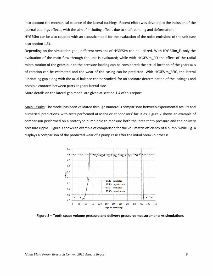
Main Results: The model has been validated through numerous comparisons between experimental results and
numerical predictions, with tests performed at Maha or at Sponsors’ facilities. Figure 2 shows an example of
comparison performed on a prototype pump able to measure both the inter-teeth pressure and the delivery
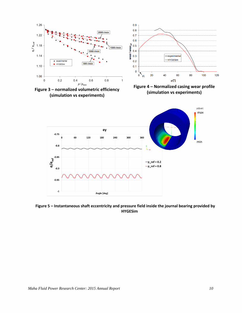
pressure ripple. Figure 3 shows an example of comparison for the volumetric efficiency of a pump, while Fig. 4
displays a comparison of the predicted wear of a pump case after the initial break-in process.
Figure 2 – Tooth space volume pressure and delivery pressure: measurements vs simulations
Maha Fluid Power Research Center: 2015 Annual Report 10
Figure 3 – normalized volumetric efficiency
(simulation vs experiments)
Figure 4 – Normalized casing wear profile
(simulation vs experiments)
Figure 5 – Instantaneous shaft eccentricity and pressure field inside the journal bearing provided by HYGESim

Maha Fluid Power Research Center: 2015 Annual Report 11
1.3. Gear generator for HYGESim
Goal: HYGESim gear generator is separate code package with interactive graphical user interface which can
generate various symmetric and asymmetric gear profiles and automatically generate the input necessary to
perform simulation with HYGESim. The gear generator also provides the geometry of the rack cutter that has
to be used to generate the gears.
Approach/Results: The HYGESim gear generator is implemented in MATLAB, and it has an interactive graphical
user interface, as shown in Figure 6 for an involute gear design. The GUI of gear generator allows the users to
visualize the design resulting from a certain set of input parameters, and to quickly generate the geometry
input files to perform HYGESim simulations.
Figure 6: Graphical User Interface of HYGESim gear generator.
HYGESim gear generator uses a numerical approach to reproduce the gear cutting process. The first step is to
generate the geometry of the rack cutter (Fig. 7). After the cutter geometry is defined, the cutting process is
simulated with relative motions of the cutter, as illustrated in Figure 8. This method has the advantage of
avoiding approximations usually introduced by analytical expressions to define the root fillet profiles of the
gears. The undercutting effect that comes from a certain tip shape can be nicely captured by this gear
generator. This can have important effect on the contact ratio parameter, occurrence of interference and on
the mechanical strength of the gears.
Maha Fluid Power Research Center: 2015 Annual Report 12
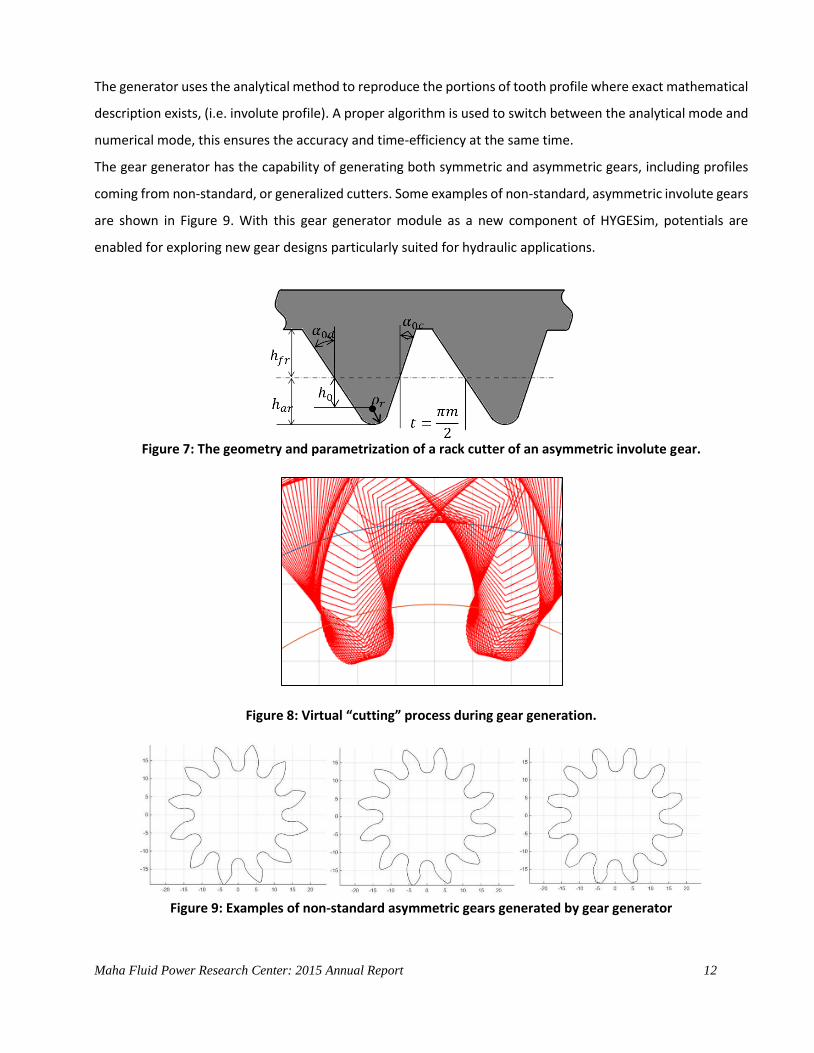
The generator uses the analytical method to reproduce the portions of tooth profile where exact mathematical
description exists, (i.e. involute profile). A proper algorithm is used to switch between the analytical mode and
numerical mode, this ensures the accuracy and time-efficiency at the same time.
The gear generator has the capability of generating both symmetric and asymmetric gears, including profiles
coming from non-standard, or generalized cutters. Some examples of non-standard, asymmetric involute gears
are shown in Figure 9. With this gear generator module as a new component of HYGESim, potentials are
enabled for exploring new gear designs particularly suited for hydraulic applications.
Figure 7: The geometry and parametrization of a rack cutter of an asymmetric involute gear.
Figure 8: Virtual “cutting” process during gear generation.
Figure 9: Examples of non-standard asymmetric gears generated by gear generator

Maha Fluid Power Research Center: 2015 Annual Report 13
1.4. Variable Delivery External Gear Machine
Goals: In this project, a novel concept for obtaining a variable delivery flow in external gear machines was
successfully conceptualized, designed and prototyped. The novel principle stands out from the existing patents
and literature available in such a way that the design maintains all the well-known advantages of external gear
machines (EGMs) such as low cost, compactness, reasonable operating efficiency and good reliability and still
capable of varying the displacement.
Approach: The proposed concept is based on the realization of a variable timing for the connections of the
tooth space volumes with the inlet/outlet grooves. The variation in the timing of the connections is achieved
by the introduction of a movable element called the “slider” within the lateral bushings of external gear
machines as shown in Figure 10(A). The position of the slider determines the amount of flow displaced by the
unit per revolution, for both the cases of pumps and motors. The displacing action occurs in the angular interval
𝜃, which defines the meshing region. Between points D and S of the line of action, the TSV is trapped between
points of contact, therefore the displacing action is realized by means of the inlet/outlet grooves (a simplified
representation of these grooves are indicated in Figure 10B). In standard EGMs, the commutation between
inlet and outlet groove is realized when the volume is minimum, so that the maximum volumetric capacity of
the pump is utilized as shown in Figure 10B.
Figure 10: (A) Slider placed inside the bearing block for achieving variable flow in an external gear machine
(B) Generic TSV at angular position ϑ and the angular interval θ in which the meshing process takes place, Groove positions in the slider to achieve max displacement.
Maha Fluid Power Research Center: 2015 Annual Report 14
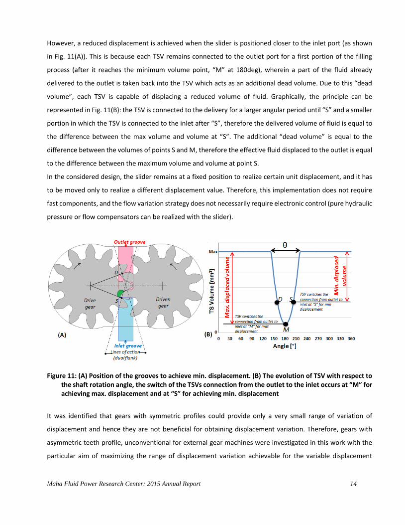
However, a reduced displacement is achieved when the slider is positioned closer to the inlet port (as shown
in Fig. 11(A)). This is because each TSV remains connected to the outlet port for a first portion of the filling
process (after it reaches the minimum volume point, “M” at 180deg), wherein a part of the fluid already
delivered to the outlet is taken back into the TSV which acts as an additional dead volume. Due to this “dead
volume”, each TSV is capable of displacing a reduced volume of fluid. Graphically, the principle can be
represented in Fig. 11(B): the TSV is connected to the delivery for a larger angular period until “S” and a smaller
portion in which the TSV is connected to the inlet after “S”, therefore the delivered volume of fluid is equal to
the difference between the max volume and volume at “S”. The additional “dead volume” is equal to the
difference between the volumes of points S and M, therefore the effective fluid displaced to the outlet is equal
to the difference between the maximum volume and volume at point S.
In the considered design, the slider remains at a fixed position to realize certain unit displacement, and it has
to be moved only to realize a different displacement value. Therefore, this implementation does not require
fast components, and the flow variation strategy does not necessarily require electronic control (pure hydraulic
pressure or flow compensators can be realized with the slider).
Figure 11: (A) Position of the grooves to achieve min. displacement. (B) The evolution of TSV with respect to the shaft rotation angle, the switch of the TSVs connection from the outlet to the inlet occurs at “M” for achieving max. displacement and at “S” for achieving min. displacement
It was identified that gears with symmetric profiles could provide only a very small range of variation of
displacement and hence they are not beneficial for obtaining displacement variation. Therefore, gears with
asymmetric teeth profile, unconventional for external gear machines were investigated in this work with the
particular aim of maximizing the range of displacement variation achievable for the variable displacement
Maha Fluid Power Research Center: 2015 Annual Report 15
external gear machine. A multi-parameter-multi-level-multi-objective genetic algorithm based optimization
procedure was developed for determining the optimal design of the gears as well as the grooves in the slider.
The performance of the design configuration was based on five different objective functions such as
maximization of reduction in displacement, minimization of flow pulsations and features of meshing process
such as internal pressure peaks & cavitation and maximization of volumetric efficiency.
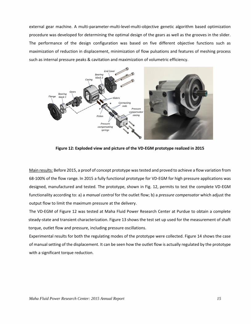
Figure 12: Exploded view and picture of the VD-EGM prototype realized in 2015
Main results: Before 2015, a proof of concept prototype was tested and proved to achieve a flow variation from
68-100% of the flow range. In 2015 a fully functional prototype for VD-EGM for high pressure applications was
designed, manufactured and tested. The prototype, shown in Fig. 12, permits to test the complete VD-EGM
functionality according to: a) a manual control for the outlet flow; b) a pressure compensator which adjust the
output flow to limit the maximum pressure at the delivery.
The VD-EGM of Figure 12 was tested at Maha Fluid Power Research Center at Purdue to obtain a complete
steady-state and transient characterization. Figure 13 shows the test set up used for the measurement of shaft
torque, outlet flow and pressure, including pressure oscillations.
Experimental results for both the regulating modes of the prototype were collected. Figure 14 shows the case
of manual setting of the displacement. It can be seen how the outlet flow is actually regulated by the prototype
with a significant torque reduction.

Maha Fluid Power Research Center: 2015 Annual Report 16
Figure 13: Test set up for the VD-EGM tests
Since the gears were not properly treated, the pressure
during the tests was limited to 100 bar. Measured data
show volumetric efficiencies in about 60% at minimum
displacement and 85% at maximum displacement. The
reduction of efficiency at maximum displacement is due to
the additional leakage path created by the slider at its back
side. This could be reduced by a better machining
tolerance of the slider, as well as by a different design
concept for the slider that introduce proper sealing.
Instead, the further reduction of volumetric efficiency at lower displacement is inevitable, due to the higher
weight of the leakages with respect to the outlet flow. This is a common feature for almost all design of VD
positive displacement units.
Figure 14: Test results achieved with the manual setting of delivery flow. Flow variation (upper plots) and torque variation (lower plots for different speeds)
Maha Fluid Power Research Center: 2015 Annual Report 17
1.5. Modeling of lubricating interfaces in external gear machines
Goals: In high pressure external gear machines (EGMs), the lubricating interfaces between lateral bushings and
gears (as shown in Figure 15A) perform important functions of sealing and bearing loads and are the major
sources of power losses in these machines. In this research, a numerical model of the lubricating gaps was
developed with an aim to gain deeper understanding of the highly coupled fluid, structural and thermal
mechanisms at these interfaces. Such an advanced computational model can be used to drive EGM designs
with improved efficiency, reliability and operating life. The research presented in this section was developed
with the following aims:
Prediction of the leakage flow, pressure & gap heights in the lateral gap
Evaluation of effects of material properties and surface features
Evaluate balancing features of the unit
Design efficient and novel machine configurations for better performance (improved balancing features,
reduction of power losses).
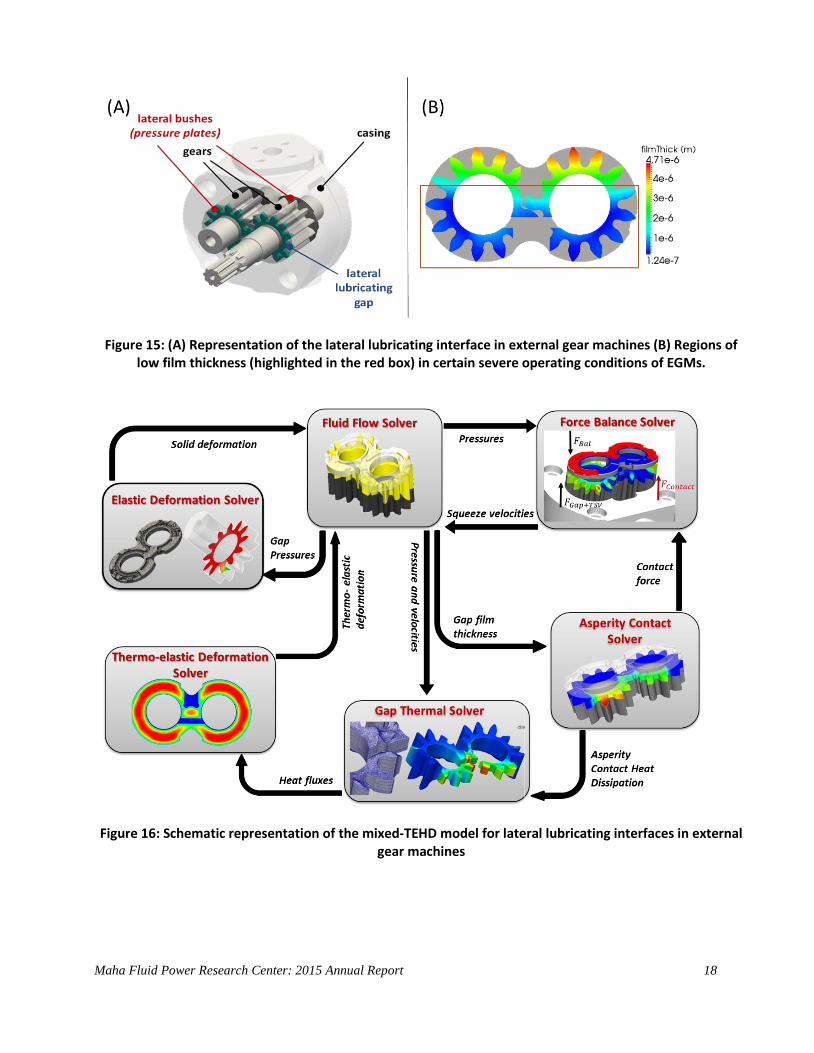
A thermo-elastohydrodynamic (TEHD) model for the lateral gaps was previously developed in Dr. Vacca’s
research team and was validated during 2014 with capacitive film thickness measurements performed on a
prototype EGM. The TEHD model for the gaps was developed with the assumption of full film lubrication at all
times during the EGM operation. However, it was observed that for some severe operating conditions involving
relatively lower pressures (< 50 bar) or lower speeds ( ~ 500 rpm), areas of mixed lubrication with very low film
thickness (as shown in Figure 15B) which are in the order of the surface roughness (~ order of 0.3 µm) of the
solid components in the gap are present. This requires that the effect of surface features of both the gears and
the lateral bushings need to be taken into account while modelling the lateral gap. For this reason, a mixed
lubrication model was added to the existing TEHD to effectively model the regions of low film thickness
whenever it is encountered in the EGM operation.
The previously developed numerical optimization procedure to determine the optimal axial balance in a given
EGM design can be used in conjunction with the TEHD model to leverage its advantages in achieving efficient
and reliable EGM designs with reduced leakages and friction losses along with reduced wear in the gears and
the lateral bushes throughout the operating range.
Maha Fluid Power Research Center: 2015 Annual Report 18
Figure 15: (A) Representation of the lateral lubricating interface in external gear machines (B) Regions of low film thickness (highlighted in the red box) in certain severe operating conditions of EGMs.
Figure 16: Schematic representation of the mixed-TEHD model for lateral lubricating interfaces in external gear machines

Maha Fluid Power Research Center: 2015 Annual Report 19
Approach: The TEHD model for the lateral lubricating gaps along with the mixed lubrication component has
been developed in programming language C ++ using open source libraries such as OpenFOAM, Linux, GSL and
gmsh. A broad structure of the numerical model with its several sub-models coupled with each other is shown
in Figure. As depicted in the figure, a gap flow sub-model calculates the flow and pressure distribution in the
lubricating gap which is coupled with structural and thermal sub-models to evaluate the elastic and thermal
deformation respectively of the lateral bushings and the gears. A force balance model is also implemented as
a sub-model to account for the dynamics and micro-motion of the bushings. An asperity contact sub-model
calculates the contact pressure when the film thickness in the gap falls in the order of the surface roughness of
the solid components. All the sub-models are coupled and implemented in an iterative numerical scheme.
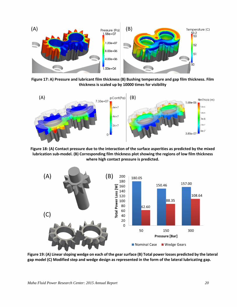
Results: The mixed-TEHD model is capable of determining the various numerous parameters associated with
the lateral gap such as pressure distribution (as shown in Figure 17A), film thickness, temperature (as shown in
Figure 17B) and deformation of the solid components. The recent addition of the mixed lubrication model also
facilitates the calculation of contact forces and pressures (as shown in Figure 18A) generated, along with heat
dissipation due to the asperity contact, whenever regions of low film thickness (as shown in Figure 18B) occurs.
Novel EGM designs – Wedge gears.
Micro surface shaping effects have been found to improve the lubrication performance in the lateral gaps and
such effects can be evaluated using the lateral lubricating gap developed in the current research. One particular
design solution of adding a linear sloping wedge to either surface of the gear teeth (as shown in Figure 19A)
was simulated using the lateral gap model and was found to reduce up to 60 % of the total power losses in the
lateral gap (as shown in Figure 19B) due to favorable hydrodynamic effects.
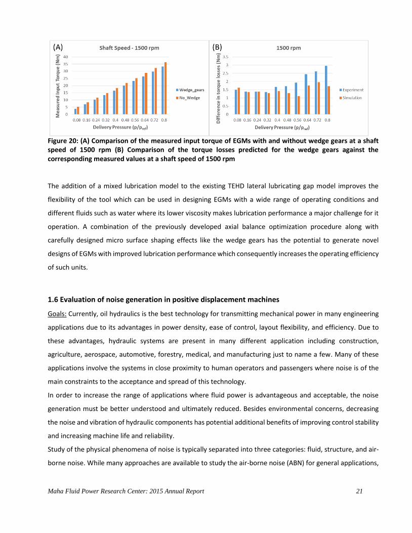
In order to verify the performance of the wedge gears experimentally, a prototype design of the wedge gears
with a flat step followed by a linear wedge (in the order of microns), as shown in Figure 19B was manufactured
and tested to validate the claims of the lubricating gap model. The measured input torque to the prototype
EGM with wedge gears was found to be consistently lower than that of the nominal EGM without the wedge
gears. This indicated that there are lesser torque losses in the wedge gears when compared to the nominal
EGM design and a sample result from a shaft speed of 1500 rpm across different delivery pressures supporting
this claim is shown in Figure 20A. The torque losses measured for the wedge gears were also compared against
the corresponding values predicted by the simulations of the gap model and were found to be in good
agreement with each other as shown in Figure 20B.
Maha Fluid Power Research Center: 2015 Annual Report 20
Figure 17: A) Pressure and lubricant film thickness (B) Bushing temperature and gap film thickness. Film
thickness is scaled up by 10000 times for visibility
Figure 18: (A) Contact pressure due to the interaction of the surface asperities as predicted by the mixed
lubrication sub-model. (B) Corresponding film thickness plot showing the regions of low film thickness where high contact pressure is predicted.
Figure 19: (A) Linear sloping wedge on each of the gear surface (B) Total power losses predicted by the lateral gap model (C) Modified step and wedge design as represented in the form of the lateral lubricating gap.
Maha Fluid Power Research Center: 2015 Annual Report 21
Figure 20: (A) Comparison of the measured input torque of EGMs with and without wedge gears at a shaft speed of 1500 rpm (B) Comparison of the torque losses predicted for the wedge gears against the corresponding measured values at a shaft speed of 1500 rpm
The addition of a mixed lubrication model to the existing TEHD lateral lubricating gap model improves the
flexibility of the tool which can be used in designing EGMs with a wide range of operating conditions and
different fluids such as water where its lower viscosity makes lubrication performance a major challenge for it
operation. A combination of the previously developed axial balance optimization procedure along with
carefully designed micro surface shaping effects like the wedge gears has the potential to generate novel
designs of EGMs with improved lubrication performance which consequently increases the operating efficiency
of such units.
1.6 Evaluation of noise generation in positive displacement machines
Goals: Currently, oil hydraulics is the best technology for transmitting mechanical power in many engineering
applications due to its advantages in power density, ease of control, layout flexibility, and efficiency. Due to
these advantages, hydraulic systems are present in many different application including construction,
agriculture, aerospace, automotive, forestry, medical, and manufacturing just to name a few. Many of these
applications involve the systems in close proximity to human operators and passengers where noise is of the
main constraints to the acceptance and spread of this technology.
In order to increase the range of applications where fluid power is advantageous and acceptable, the noise
generation must be better understood and ultimately reduced. Besides environmental concerns, decreasing
the noise and vibration of hydraulic components has potential additional benefits of improving control stability
and increasing machine life and reliability.
Study of the physical phenomena of noise is typically separated into three categories: fluid, structure, and air-
borne noise. While many approaches are available to study the air-borne noise (ABN) for general applications,

Maha Fluid Power Research Center: 2015 Annual Report 22
it is difficult to simulate the mechanisms of noise generation in hydrostatic units to predict the fluid-borne noise
(FBN) and structure-borne noise (SBN).
The current activity focuses in advance the understanding of the noise generation and propagation in positive
displacement machines, taking as reference the particular case of external gear pumps. More specifically, it is
to enhance understanding of the phenomena relating the instantaneous pressure and flow fluctuations to the
noise radiated by the unit, and to formulate ideas for quieter design of pumps and motors.
Figure 21: Approach of study: FBN – SBN – ABN in an external gear machines
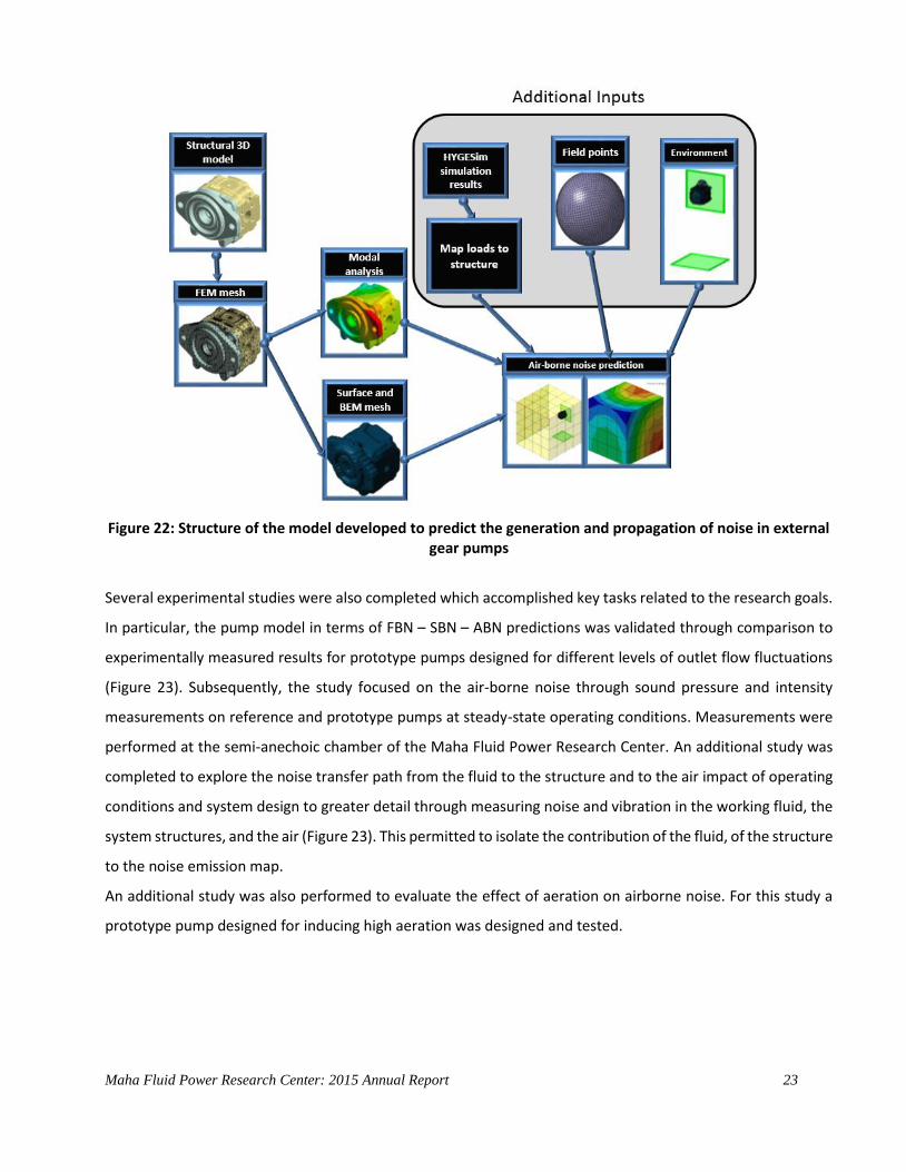
Approach: The case of external gear pumps is taken as reference for a new model suitable to study the
generation and transmission of noise from the sources out to the environment (Figure 21). The lumped
parameter model HYGESim (Hydraulic Gear machine Simulator) is adapted to provide the loading pressure
functions and to predict interactions with the attached system. The different loading functions are then applied
to vibro-acoustic models for evaluation of noise transmission. Vibration and sound radiation can be predicted
using a combined finite element and boundary element vibro-acoustic model as well as additional models of
system components to better understand the essential problems of noise generation. The main structure of
the model is shown in Figure 22.
Maha Fluid Power Research Center: 2015 Annual Report 23
Figure 22: Structure of the model developed to predict the generation and propagation of noise in external gear pumps
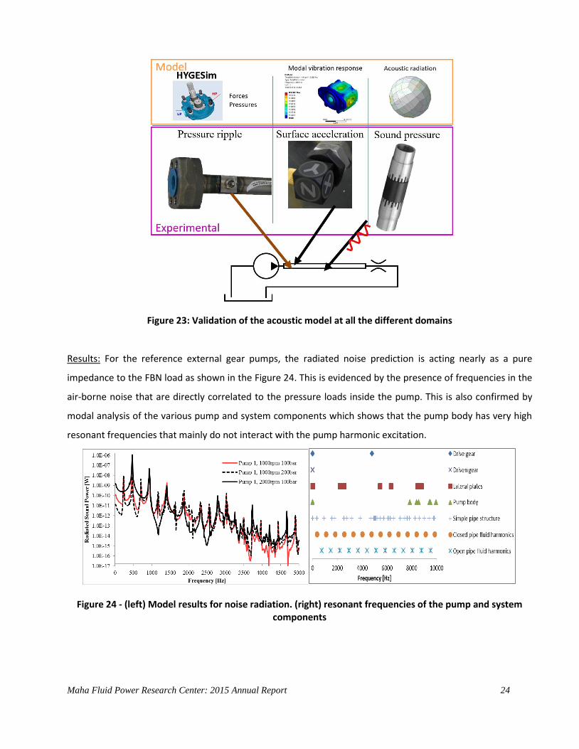
Several experimental studies were also completed which accomplished key tasks related to the research goals.
In particular, the pump model in terms of FBN – SBN – ABN predictions was validated through comparison to
experimentally measured results for prototype pumps designed for different levels of outlet flow fluctuations
(Figure 23). Subsequently, the study focused on the air-borne noise through sound pressure and intensity
measurements on reference and prototype pumps at steady-state operating conditions. Measurements were
performed at the semi-anechoic chamber of the Maha Fluid Power Research Center. An additional study was
completed to explore the noise transfer path from the fluid to the structure and to the air impact of operating
conditions and system design to greater detail through measuring noise and vibration in the working fluid, the
system structures, and the air (Figure 23). This permitted to isolate the contribution of the fluid, of the structure
to the noise emission map.
An additional study was also performed to evaluate the effect of aeration on airborne noise. For this study a
prototype pump designed for inducing high aeration was designed and tested.
Maha Fluid Power Research Center: 2015 Annual Report 24
Figure 23: Validation of the acoustic model at all the different domains
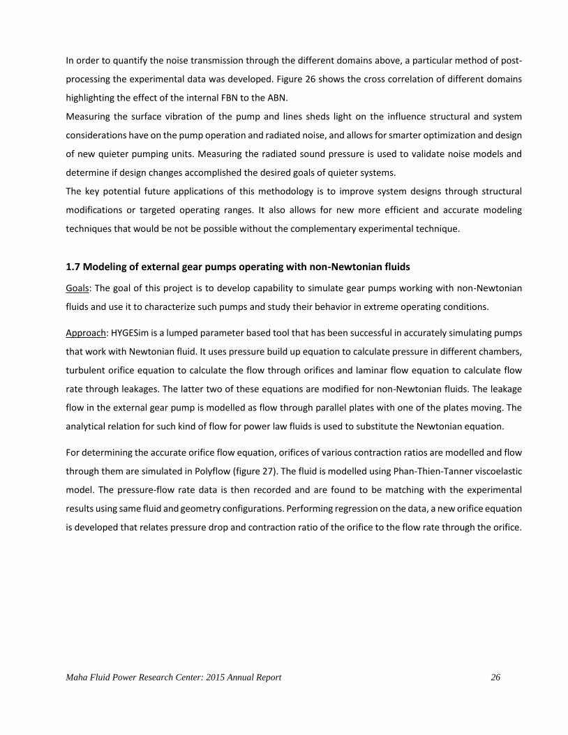
Results: For the reference external gear pumps, the radiated noise prediction is acting nearly as a pure
impedance to the FBN load as shown in the Figure 24. This is evidenced by the presence of frequencies in the
air-borne noise that are directly correlated to the pressure loads inside the pump. This is also confirmed by
modal analysis of the various pump and system components which shows that the pump body has very high
resonant frequencies that mainly do not interact with the pump harmonic excitation.
Figure 24 - (left) Model results for noise radiation. (right) resonant frequencies of the pump and system components

Maha Fluid Power Research Center: 2015 Annual Report 25
Figure 25 – Pressure waves propagation in the pump delivery line
Figure 26 – Cross correlation of FBN SBN and ABN to understand noise propagation in the pump
An additional study shows that components of the system including the attached lines and the oil inside them
have strong potential to show resonant coupling with the pump frequencies (Fig. 25). Vibration in the steel pipe
utilized in the experiments as delivery apparatus to characterize the FBN according to the ISO standard are
influenced by resonances of both the fluid inside the pipe and the pipe structure.
Maha Fluid Power Research Center: 2015 Annual Report 26
In order to quantify the noise transmission through the different domains above, a particular method of post-
processing the experimental data was developed. Figure 26 shows the cross correlation of different domains
highlighting the effect of the internal FBN to the ABN.
Measuring the surface vibration of the pump and lines sheds light on the influence structural and system
considerations have on the pump operation and radiated noise, and allows for smarter optimization and design
of new quieter pumping units. Measuring the radiated sound pressure is used to validate noise models and
determine if design changes accomplished the desired goals of quieter systems.
The key potential future applications of this methodology is to improve system designs through structural
modifications or targeted operating ranges. It also allows for new more efficient and accurate modeling
techniques that would be not be possible without the complementary experimental technique.
1.7 Modeling of external gear pumps operating with non-Newtonian fluids
Goals: The goal of this project is to develop capability to simulate gear pumps working with non-Newtonian
fluids and use it to characterize such pumps and study their behavior in extreme operating conditions.
Approach: HYGESim is a lumped parameter based tool that has been successful in accurately simulating pumps
that work with Newtonian fluid. It uses pressure build up equation to calculate pressure in different chambers,
turbulent orifice equation to calculate the flow through orifices and laminar flow equation to calculate flow
rate through leakages. The latter two of these equations are modified for non-Newtonian fluids. The leakage
flow in the external gear pump is modelled as flow through parallel plates with one of the plates moving. The
analytical relation for such kind of flow for power law fluids is used to substitute the Newtonian equation.
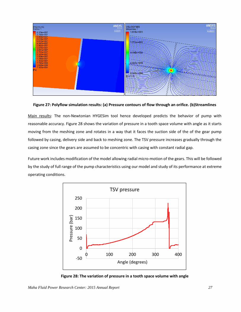
For determining the accurate orifice flow equation, orifices of various contraction ratios are modelled and flow
through them are simulated in Polyflow (figure 27). The fluid is modelled using Phan-Thien-Tanner viscoelastic
model. The pressure-flow rate data is then recorded and are found to be matching with the experimental
results using same fluid and geometry configurations. Performing regression on the data, a new orifice equation
is developed that relates pressure drop and contraction ratio of the orifice to the flow rate through the orifice.
Maha Fluid Power Research Center: 2015 Annual Report 27
Figure 27: Polyflow simulation results: (a) Pressure contours of flow through an orifice. (b)Streamlines
Main results: The non-Newtonian HYGESim tool hence developed predicts the behavior of pump with
reasonable accuracy. Figure 28 shows the variation of pressure in a tooth space volume with angle as it starts
moving from the meshing zone and rotates in a way that it faces the suction side of the of the gear pump
followed by casing, delivery side and back to meshing zone. The TSV pressure increases gradually through the
casing zone since the gears are assumed to be concentric with casing with constant radial gap.
Future work includes modification of the model allowing radial micro-motion of the gears. This will be followed
by the study of full range of the pump characteristics using our model and study of its performance at extreme
operating conditions.
Figure 28: The variation of pressure in a tooth space volume with angle
-50
0
50
100
150
200
250
0 100 200 300 400
Pre
ssu
re (
bar
)
Angle (degrees)
TSV pressure

Maha Fluid Power Research Center: 2015 Annual Report 28
1.8 Modeling of Gerotor units
Goal: This research focuses on the development of a simulation model that can be used to study the operation
of Gerotor pumps and as a design tool for investigating new solutions. The model takes into account for the
main fluid dynamics of the displacing process realized by the machine, considering also the mechanical
interaction of the components, particularly as concerns the micro-motions of the rotors. The developed tool is
capable of generating the geometry profiles or start from an existing CAD design of the rotors and simulate its
operation within AMESim, predicting main features of the operation such as delivery pressure ripples, internal
pressure peaks, rotor radial movements and torque losses.
Approach: The model is based on a multi domain simulation approach comprising sub-models for parametric
geometry generation, numerical calculation of characteristic geometry data, fluid dynamic model and
mechanical model (Figure 29).
A geometric generator of rotors based on the circular arc profile for the outer rotor was also created (Figure
30). The simulation model, however, accepts any profile for the rotors.
Figure 29 – Structure of the Gerotor Simulation Tool: Interaction between the internal modules and an
external hydraulic system

Maha Fluid Power Research Center: 2015 Annual Report 29
Figure 30 – Graphical user interface for the GEROTOR profile generator
Once the geometry of the rotors has been defined, using the in-house Geometry Generator or a predefined
profile are carried out, the C/C++ code evaluates the geometrical features of the pump. In particular, it
evaluates the Displacement Chambers Volumes (DCV), the inlet and outlet areas (intersection between the DCV
and the grooves as depicted in Figure 31 and Figure 32A/B ) and the radial gap between the teeth of the inner
and outer rotor along with the length of the gap (Figure 30C).
Figure 31 – Control Volumes and Intersection with Delivery (red) and Suction(blue) Ports
Maha Fluid Power Research Center: 2015 Annual Report 30
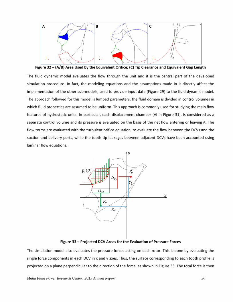
Figure 32 – (A/B) Area Used by the Equivalent Orifice; (C) Tip Clearance and Equivalent Gap Length
The fluid dynamic model evaluates the flow through the unit and it is the central part of the developed
simulation procedure. In fact, the modeling equations and the assumptions made in it directly affect the
implementation of the other sub-models, used to provide input data (Figure 29) to the fluid dynamic model.
The approach followed for this model is lumped parameters: the fluid domain is divided in control volumes in
which fluid properties are assumed to be uniform. This approach is commonly used for studying the main flow
features of hydrostatic units. In particular, each displacement chamber (Vi in Figure 31), is considered as a
separate control volume and its pressure is evaluated on the basis of the net flow entering or leaving it. The
flow terms are evaluated with the turbulent orifice equation, to evaluate the flow between the DCVs and the
suction and delivery ports, while the tooth tip leakages between adjacent DCVs have been accounted using
laminar flow equations.
Figure 33 – Projected DCV Areas for the Evaluation of Pressure Forces
The simulation model also evaluates the pressure forces acting on each rotor. This is done by evaluating the
single force components in each DCV in x and y axes. Thus, the surface corresponding to each tooth profile is
projected on a plane perpendicular to the direction of the force, as shown in Figure 33. The total force is then
Maha Fluid Power Research Center: 2015 Annual Report 31
utilized in a journal bearing model to evaluate the actual position of the two rotors. This last information is
used to carefully determine geometric parameters such as DCV volume, throat areas and the radial gaps. The
micro motion evaluation plays a fundamental role on not only the prediction of the fluid dynamic features but
also on the mechanical interaction between the rotors of the unit. The coupling of the mechanical module and
the geometrical module of the current simulation model can be used as a valuable tool to estimate the
correlation between the rotors profile geometry and factors responsible for the wear of the components
namely contact pressure, sliding velocity and curvature of the profile putting the accent on the actual regions
where contact occurs.
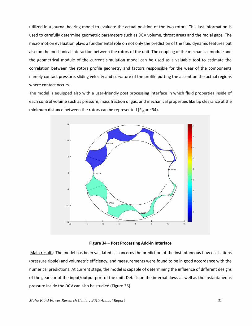
The model is equipped also with a user-friendly post processing interface in which fluid properties inside of
each control volume such as pressure, mass fraction of gas, and mechanical properties like tip clearance at the
minimum distance between the rotors can be represented (Figure 34).
Figure 34 – Post Processing Add-in Interface
Main results: The model has been validated as concerns the prediction of the instantaneous flow oscillations
(pressure ripple) and volumetric efficiency, and measurements were found to be in good accordance with the
numerical predictions. At current stage, the model is capable of determining the influence of different designs
of the gears or of the input/output port of the unit. Details on the internal flows as well as the instantaneous
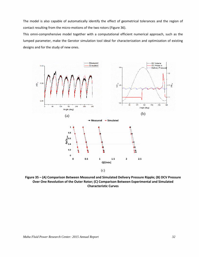
pressure inside the DCV can also be studied (Figure 35).
Maha Fluid Power Research Center: 2015 Annual Report 32
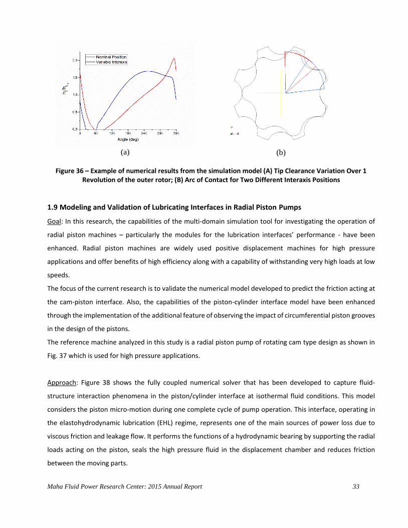
The model is also capable of automatically identify the effect of geometrical tolerances and the region of
contact resulting from the micro-motions of the two rotors (Figure 36).
This omni-comprehensive model together with a computational efficient numerical approach, such as the
lumped parameter, make the Gerotor simulation tool ideal for characterization and optimization of existing
designs and for the study of new ones.
(a)
(b)
(c)
Figure 35 – (A) Comparison Between Measured and Simulated Delivery Pressure Ripple; (B) DCV Pressure Over One Revolution of the Outer Rotor; (C) Comparison Between Experimental and Simulated
Characteristic Curves
Maha Fluid Power Research Center: 2015 Annual Report 33
(a)
(b)
Figure 36 – Example of numerical results from the simulation model (A) Tip Clearance Variation Over 1
Revolution of the outer rotor; (B) Arc of Contact for Two Different Interaxis Positions
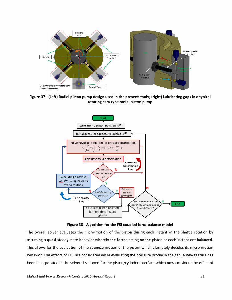
1.9 Modeling and Validation of Lubricating Interfaces in Radial Piston Pumps
Goal: In this research, the capabilities of the multi-domain simulation tool for investigating the operation of
radial piston machines – particularly the modules for the lubrication interfaces’ performance - have been
enhanced. Radial piston machines are widely used positive displacement machines for high pressure
applications and offer benefits of high efficiency along with a capability of withstanding very high loads at low
speeds.
The focus of the current research is to validate the numerical model developed to predict the friction acting at
the cam-piston interface. Also, the capabilities of the piston-cylinder interface model have been enhanced
through the implementation of the additional feature of observing the impact of circumferential piston grooves
in the design of the pistons.
The reference machine analyzed in this study is a radial piston pump of rotating cam type design as shown in
Fig. 37 which is used for high pressure applications.
Approach: Figure 38 shows the fully coupled numerical solver that has been developed to capture fluid-
structure interaction phenomena in the piston/cylinder interface at isothermal fluid conditions. This model
considers the piston micro-motion during one complete cycle of pump operation. This interface, operating in
the elastohydrodynamic lubrication (EHL) regime, represents one of the main sources of power loss due to
viscous friction and leakage flow. It performs the functions of a hydrodynamic bearing by supporting the radial
loads acting on the piston, seals the high pressure fluid in the displacement chamber and reduces friction
between the moving parts.
Maha Fluid Power Research Center: 2015 Annual Report 34
Figure 37 - (Left) Radial piston pump design used in the present study; (right) Lubricating gaps in a typical rotating cam type radial piston pump
Figure 38 - Algorithm for the FSI coupled force balance model
The overall solver evaluates the micro-motion of the piston during each instant of the shaft’s rotation by
assuming a quasi-steady state behavior wherein the forces acting on the piston at each instant are balanced.
This allows for the evaluation of the squeeze motion of the piston which ultimately decides its micro-motion
behavior. The effects of EHL are considered while evaluating the pressure profile in the gap. A new feature has
been incorporated in the solver developed for the piston/cylinder interface which now considers the effect of
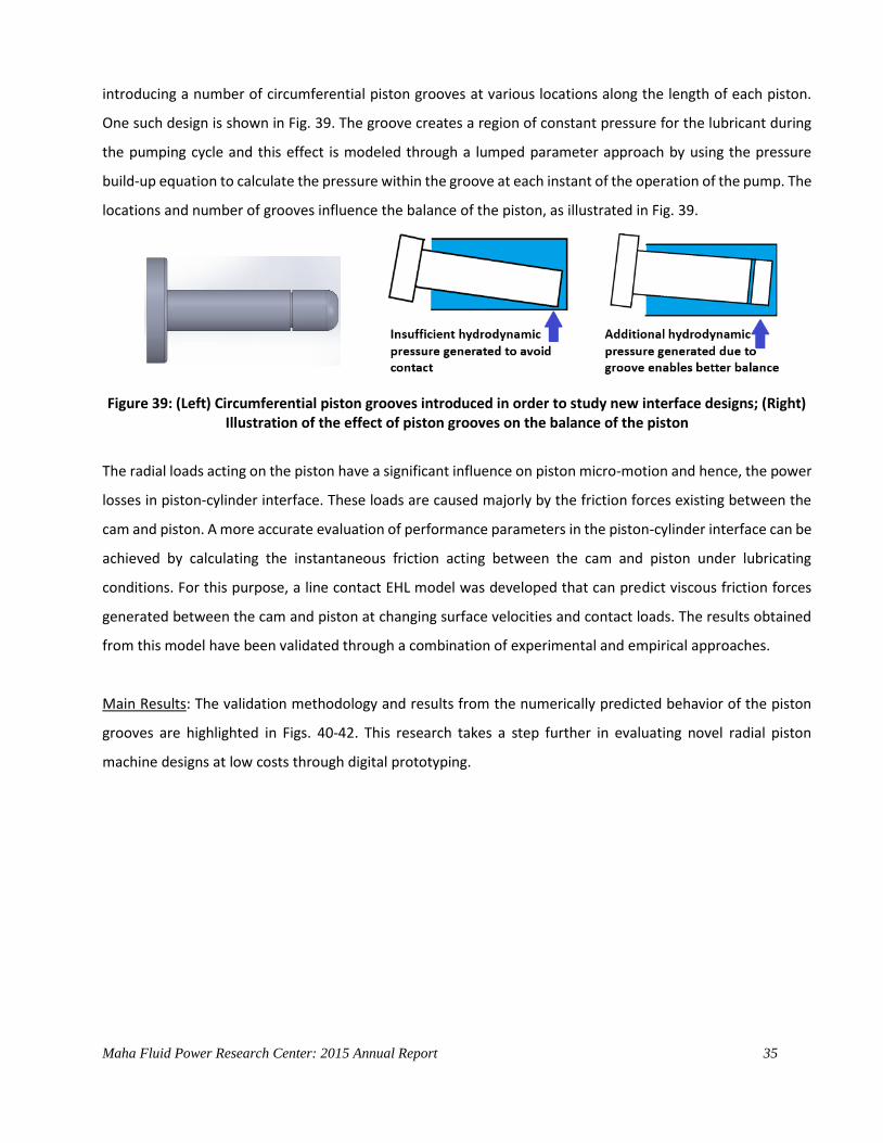
Maha Fluid Power Research Center: 2015 Annual Report 35
introducing a number of circumferential piston grooves at various locations along the length of each piston.
One such design is shown in Fig. 39. The groove creates a region of constant pressure for the lubricant during
the pumping cycle and this effect is modeled through a lumped parameter approach by using the pressure
build-up equation to calculate the pressure within the groove at each instant of the operation of the pump. The
locations and number of grooves influence the balance of the piston, as illustrated in Fig. 39.
Figure 39: (Left) Circumferential piston grooves introduced in order to study new interface designs; (Right) Illustration of the effect of piston grooves on the balance of the piston
The radial loads acting on the piston have a significant influence on piston micro-motion and hence, the power
losses in piston-cylinder interface. These loads are caused majorly by the friction forces existing between the
cam and piston. A more accurate evaluation of performance parameters in the piston-cylinder interface can be
achieved by calculating the instantaneous friction acting between the cam and piston under lubricating
conditions. For this purpose, a line contact EHL model was developed that can predict viscous friction forces
generated between the cam and piston at changing surface velocities and contact loads. The results obtained
from this model have been validated through a combination of experimental and empirical approaches.
Main Results: The validation methodology and results from the numerically predicted behavior of the piston
grooves are highlighted in Figs. 40-42. This research takes a step further in evaluating novel radial piston
machine designs at low costs through digital prototyping.

Maha Fluid Power Research Center: 2015 Annual Report 36
Figure 40: (Left) Flow rates entering the groove from its either side during one shaft revolution; (Right) Pressure within the groove as a function of shaft angle. Operating condition: Outlet pressure=700 bar, Shaft
speed=1800 rpm.
At present, work is on-going on the evaluation of the effect of mixed lubrication within the piston/cylinder
interface and the effect of grooves under such lubricating conditions. Future work includes the incorporation
of thermal effects in evaluating lubricating gap flows to realize a more accurate model of radial piston pumps.
Figure 41: (Left) Instantaneous film thicknesses and (Right) Pressure profile in the lubricating gap domain over one shaft revolution using FSI model. Operating condition: Outlet pressure=700 bar, Shaft speed=1800
rpm.

Maha Fluid Power Research Center: 2015 Annual Report 37
Figure 42: (Left) Experimental measurement of the angular velocity of the cam to serve as an accurate input to the numerical model; (Right) Force balance of the cam to validate friction coefficient results
1.10 Modeling and Simulation of Cavitation in Fluid Power systems
Goal: This research focuses on modeling and simulation of cavitation in hydraulic systems. Cavitation is
traditionally known to cause damage to fluid machinery and is a bottleneck for fluid power applications that
involve dealing with high gas content in fluids or high shear stresses during operation. This is true for most of
the pumps connected to open reservoirs; therefore in all open loop hydraulic circuits and at the inlet of charge
pumps closed loops circuits. Also in other elements of closed loop system, cavitation can limit the performance
of the hydraulic components, create damages or produce noise. Therefore, it is imperative to model such
effects, in order to improve the energetic performance of fluid power systems. This research entails
implementation of effects of cavitation using the popular Lumped Parameter Modeling approach.
Approach: During the past research effort at Dr. Vacca’s team, an approach for the prediction of air release and
absorption in hydraulic oils was formulated. The proposed approach is derived from the Rayleigh Plesset
Equation used to describe bubble dynamics in fluids. With a few additional assumptions, a lumped parameter
model was derived to accounts for the effects of the dynamic features of air release and absorption. This
modeling approach is unique in the aspects of capturing the dynamic evolution of gas and vapor phases in
hydraulic oils. This has been achieved by analyzing the effects of compressibility in lumped parameter models
used to describe hydraulic systems.
The effects of compressibility have been observed in the form of reduced overall stiffness of the system as well
as reduced volumetric flow rate across orifices. The widely used Orifice and Pressure built up equations alone
Maha Fluid Power Research Center: 2015 Annual Report 38
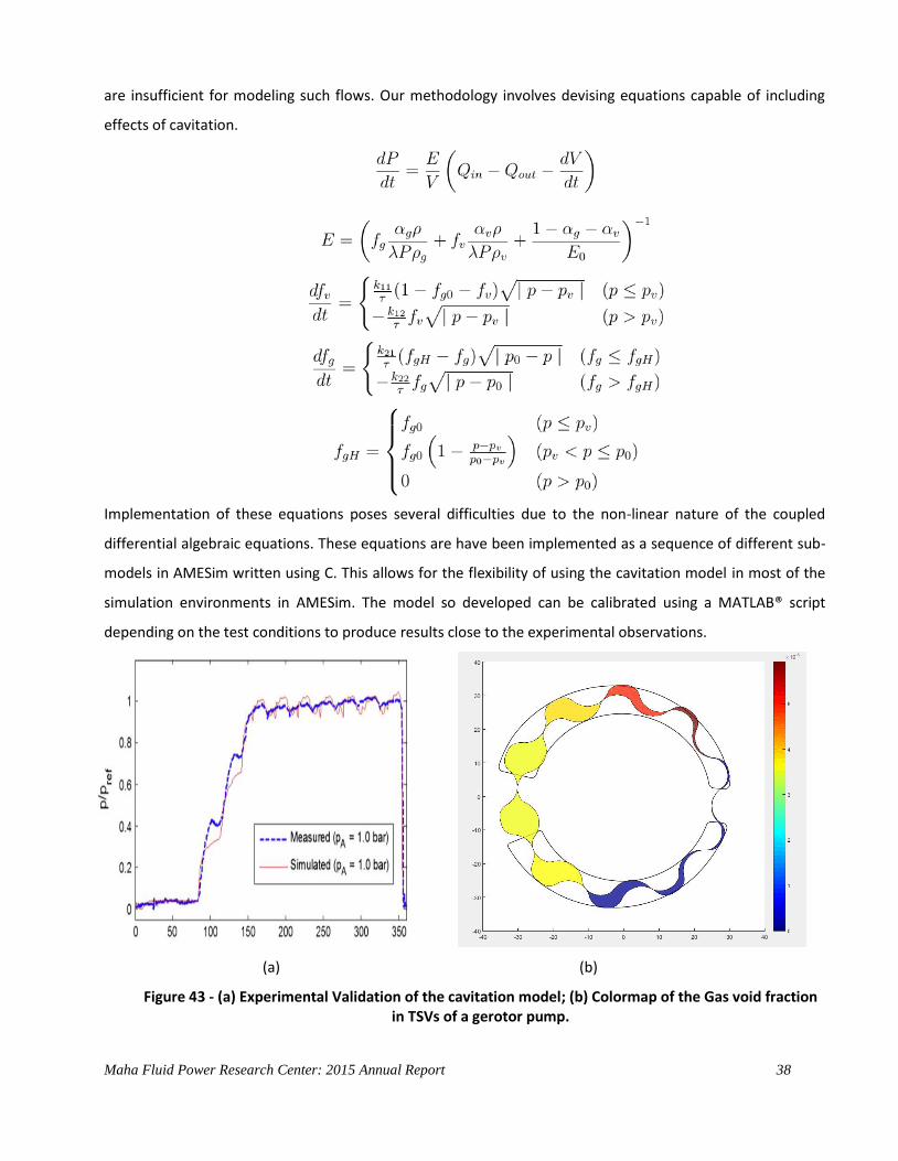
are insufficient for modeling such flows. Our methodology involves devising equations capable of including
effects of cavitation.
Implementation of these equations poses several difficulties due to the non-linear nature of the coupled
differential algebraic equations. These equations are have been implemented as a sequence of different sub-
models in AMESim written using C. This allows for the flexibility of using the cavitation model in most of the
simulation environments in AMESim. The model so developed can be calibrated using a MATLAB® script
depending on the test conditions to produce results close to the experimental observations.
(a) (b)
Figure 43 - (a) Experimental Validation of the cavitation model; (b) Colormap of the Gas void fraction in TSVs of a gerotor pump.
Maha Fluid Power Research Center: 2015 Annual Report 39
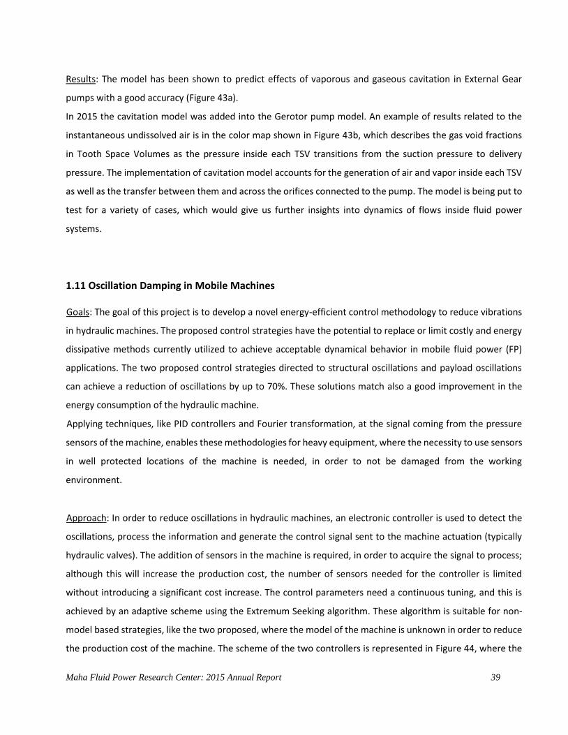
Results: The model has been shown to predict effects of vaporous and gaseous cavitation in External Gear
pumps with a good accuracy (Figure 43a).
In 2015 the cavitation model was added into the Gerotor pump model. An example of results related to the
instantaneous undissolved air is in the color map shown in Figure 43b, which describes the gas void fractions
in Tooth Space Volumes as the pressure inside each TSV transitions from the suction pressure to delivery
pressure. The implementation of cavitation model accounts for the generation of air and vapor inside each TSV
as well as the transfer between them and across the orifices connected to the pump. The model is being put to
test for a variety of cases, which would give us further insights into dynamics of flows inside fluid power
systems.
1.11 Oscillation Damping in Mobile Machines
Goals: The goal of this project is to develop a novel energy-efficient control methodology to reduce vibrations
in hydraulic machines. The proposed control strategies have the potential to replace or limit costly and energy
dissipative methods currently utilized to achieve acceptable dynamical behavior in mobile fluid power (FP)
applications. The two proposed control strategies directed to structural oscillations and payload oscillations
can achieve a reduction of oscillations by up to 70%. These solutions match also a good improvement in the
energy consumption of the hydraulic machine.
Applying techniques, like PID controllers and Fourier transformation, at the signal coming from the pressure
sensors of the machine, enables these methodologies for heavy equipment, where the necessity to use sensors
in well protected locations of the machine is needed, in order to not be damaged from the working
environment.
Approach: In order to reduce oscillations in hydraulic machines, an electronic controller is used to detect the
oscillations, process the information and generate the control signal sent to the machine actuation (typically
hydraulic valves). The addition of sensors in the machine is required, in order to acquire the signal to process;
although this will increase the production cost, the number of sensors needed for the controller is limited
without introducing a significant cost increase. The control parameters need a continuous tuning, and this is
achieved by an adaptive scheme using the Extremum Seeking algorithm. These algorithm is suitable for non-
model based strategies, like the two proposed, where the model of the machine is unknown in order to reduce
the production cost of the machine. The scheme of the two controllers is represented in Figure 44, where the
Maha Fluid Power Research Center: 2015 Annual Report 40
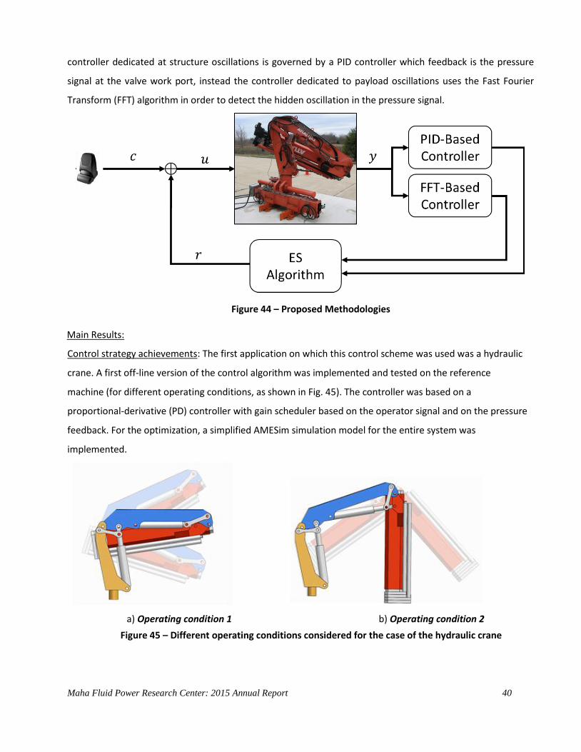
controller dedicated at structure oscillations is governed by a PID controller which feedback is the pressure
signal at the valve work port, instead the controller dedicated to payload oscillations uses the Fast Fourier
Transform (FFT) algorithm in order to detect the hidden oscillation in the pressure signal.
Figure 44 – Proposed Methodologies
Main Results:
Control strategy achievements: The first application on which this control scheme was used was a hydraulic
crane. A first off-line version of the control algorithm was implemented and tested on the reference
machine (for different operating conditions, as shown in Fig. 45). The controller was based on a
proportional-derivative (PD) controller with gain scheduler based on the operator signal and on the pressure
feedback. For the optimization, a simplified AMESim simulation model for the entire system was
implemented.
a) Operating condition 1 b) Operating condition 2
Figure 45 – Different operating conditions considered for the case of the hydraulic crane
Maha Fluid Power Research Center: 2015 Annual Report 41
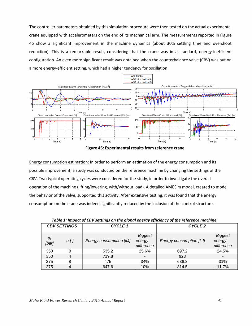
The controller parameters obtained by this simulation procedure were then tested on the actual experimental
crane equipped with accelerometers on the end of its mechanical arm. The measurements reported in Figure
46 show a significant improvement in the machine dynamics (about 30% settling time and overshoot
reduction). This is a remarkable result, considering that the crane was in a standard, energy-inefficient
configuration. An even more significant result was obtained when the counterbalance valve (CBV) was put on
a more energy-efficient setting, which had a higher tendency for oscillation.
Figure 46: Experimental results from reference crane
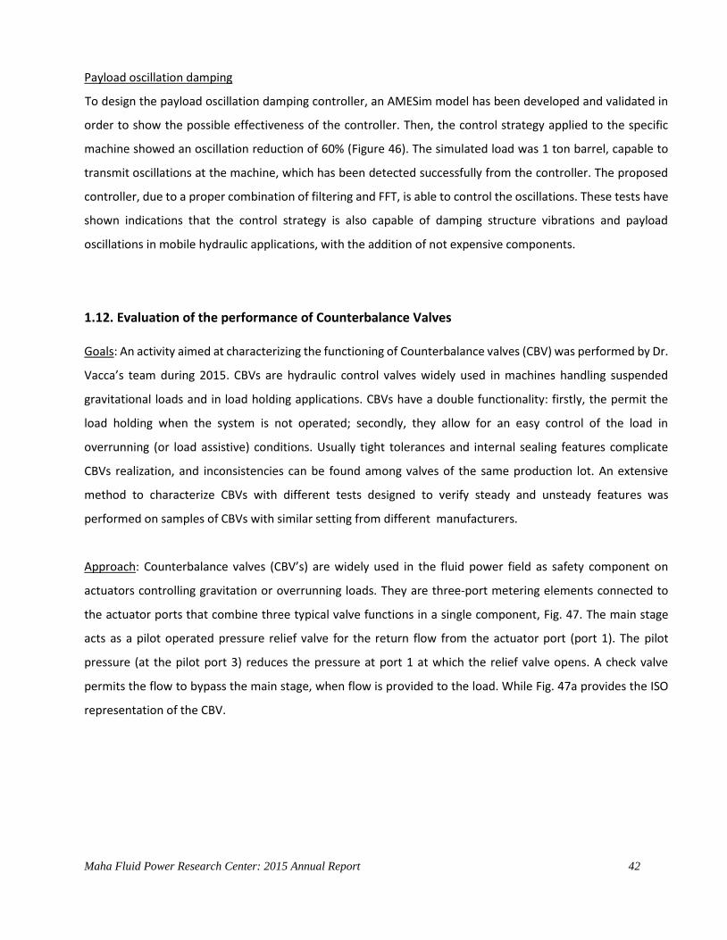
Energy consumption estimation: In order to perform an estimation of the energy consumption and its
possible improvement, a study was conducted on the reference machine by changing the settings of the
CBV. Two typical operating cycles were considered for the study, in order to investigate the overall
operation of the machine (lifting/lowering, with/without load). A detailed AMESim model, created to model
the behavior of the valve, supported this activity. After extensive testing, it was found that the energy
consumption on the crane was indeed significantly reduced by the inclusion of the control structure.
Table 1: Impact of CBV settings on the global energy efficiency of the reference machine.
CBV SETTINGS CYCLE 1 CYCLE 2
ps [bar]
α [-] Energy consumption [kJ] Biggest
energy
difference Energy consumption [kJ]
Biggest
energy
difference 350 8 535.2 25.6% 697.2 24.5% 350 4 719.8 - 923 - 275 8 475 34% 636.8 31% 275 4 647.6 10% 814.5 11.7%
Maha Fluid Power Research Center: 2015 Annual Report 42
Payload oscillation damping
To design the payload oscillation damping controller, an AMESim model has been developed and validated in
order to show the possible effectiveness of the controller. Then, the control strategy applied to the specific
machine showed an oscillation reduction of 60% (Figure 46). The simulated load was 1 ton barrel, capable to
transmit oscillations at the machine, which has been detected successfully from the controller. The proposed
controller, due to a proper combination of filtering and FFT, is able to control the oscillations. These tests have
shown indications that the control strategy is also capable of damping structure vibrations and payload
oscillations in mobile hydraulic applications, with the addition of not expensive components.
1.12. Evaluation of the performance of Counterbalance Valves
Goals: An activity aimed at characterizing the functioning of Counterbalance valves (CBV) was performed by Dr.
Vacca’s team during 2015. CBVs are hydraulic control valves widely used in machines handling suspended
gravitational loads and in load holding applications. CBVs have a double functionality: firstly, the permit the
load holding when the system is not operated; secondly, they allow for an easy control of the load in
overrunning (or load assistive) conditions. Usually tight tolerances and internal sealing features complicate
CBVs realization, and inconsistencies can be found among valves of the same production lot. An extensive
method to characterize CBVs with different tests designed to verify steady and unsteady features was
performed on samples of CBVs with similar setting from different manufacturers.
Approach: Counterbalance valves (CBV’s) are widely used in the fluid power field as safety component on
actuators controlling gravitation or overrunning loads. They are three-port metering elements connected to
the actuator ports that combine three typical valve functions in a single component, Fig. 47. The main stage
acts as a pilot operated pressure relief valve for the return flow from the actuator port (port 1). The pilot
pressure (at the pilot port 3) reduces the pressure at port 1 at which the relief valve opens. A check valve
permits the flow to bypass the main stage, when flow is provided to the load. While Fig. 47a provides the ISO
representation of the CBV.
Maha Fluid Power Research Center: 2015 Annual Report 43
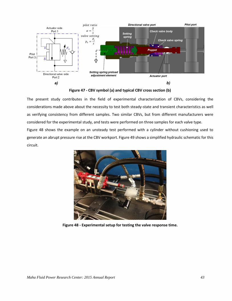
Figure 47 - CBV symbol (a) and typical CBV cross section (b)
The present study contributes in the field of experimental characterization of CBVs, considering the
considerations made above about the necessity to test both steady-state and transient characteristics as well
as verifying consistency from different samples. Two similar CBVs, but from different manufacturers were
considered for the experimental study, and tests were performed on three samples for each valve type.
Figure 48 shows the example on an unsteady test performed with a cylinder without cushioning used to
generate an abrupt pressure rise at the CBV workport. Figure 49 shows a simplified hydraulic schematic for this
circuit.
Figure 48 - Experimental setup for testing the valve response time.

Maha Fluid Power Research Center: 2015 Annual Report 44
Figure 49 – hydraulic schematic for the valve response time test.
Eight different tests were performed to verify the steady state pressure drop curve, the hysteresis features, the
response time, the CBV operation as relief; as check and under piloting conditions.
Results: Results were obtained considering valves with similar specifications but from two different
manufacturers. To check the quality of the valve in terms of consistency and repeatability, the tests involved 3
samples for each valve. Figure 50 shows an example of measured valve response. Considerations about the
equivalent transfer function of the valve were made. Moreover, a numerical model previously developed at
Maha by Dr. Vacca’s team was validated on the basis of the experimental campaign made on the two reference
valves.
Figure 50 – example of measured valve response.

Maha Fluid Power Research Center: 2015 Annual Report 45
2 Research Facilities
Lab Space and Test Rigs at Maha The lab currently houses ten test rigs designed to support our research.
Test beds for technological demonstration (Left)
Test rigs and car lift (Above)
and new lab space (Left)

Maha Fluid Power Research Center: 2015 Annual Report 46
EHD Test Rig
The EHD test rig is designed to measure the dynamic pressure
field in the gap between piston and cylinder and the surface
temperature distribution in the cylinder of a swash plate axial
piston pump. A special test pump with a single piston
cylinder assembly has been designed for this test rig.
EHD Pump Measured Temperature Field in the
Piston/Cylinder Gap
Test Rigs for Steady State Measurements
Two electric motor driven test rigs have been designed to
measure steady state and dynamic characteristics for
different pump and motor types including 1 rpm tests. The
test rigs are equipped with temperature and pressure
sensors as well as speed, flow and torque meters.
Performance Characteristics Max. installed electric power: 2 x 120 kW Max. speed: n1 = 7000 rpm/n2 = 3000 rpm Max. pressure: 450 bar Max. torque: M1 = 300 Nm/ M2 = 500 Nm

Maha Fluid Power Research Center: 2015 Annual Report 47
OLEMS Test Rig
This rig is designed to investigate the temperature behavior in
swash plate axial piston pumps. Sixty thermocouples are
mounted around a single cylinder to measure the
temperature field during operation of the pump. Telemetry is
used for data transfer from the rotating cylinder block to the
data acquisition board. The measured results are used for the
development of a more precise method to calculate the non-
isothermal gap flow between piston and cylinder in swash
plate type axial piston machines.
Temperature distribution in the assembly near the slipper slide
Test Rig to Study Active Vibration Damping of the
Swash Plate
A 75cc pump is modified to implement active
vibration control using the swash plate. One tri-axial
acceleration sensor and one angle sensor is installed
on the swash plate and a high speed servovalve is
attached on the back of the pump case. The higher
harmonic least mean square algorithm gives signal
to the servovalve to generate destructive
interference force for the swash plate moment. An
experimetal test is conducted using Labview FPGA
interface via cRIO to investigate the performance of
active vibration control.
Maha Fluid Power Research Center: 2015 Annual Report 48
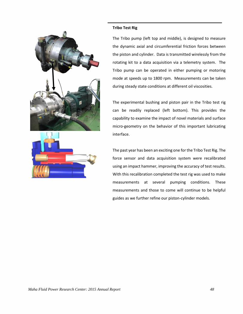
Tribo Test Rig
The Tribo pump (left top and middle), is designed to measure
the dynamic axial and circumferential friction forces between
the piston and cylinder. Data is transmitted wirelessly from the
rotating kit to a data acquisition via a telemetry system. The
Tribo pump can be operated in either pumping or motoring
mode at speeds up to 1800 rpm. Measurements can be taken
during steady state conditions at different oil viscosities.
The experimental bushing and piston pair in the Tribo test rig
can be readily replaced (left bottom). This provides the
capability to examine the impact of novel materials and surface
micro-geometry on the behavior of this important lubricating
interface.
The past year has been an exciting one for the Tribo Test Rig. The
force sensor and data acquisition system were recalibrated
using an impact hammer, improving the accuracy of test results.
With this recalibration completed the test rig was used to make
measurements at several pumping conditions. These
measurements and those to come will continue to be helpful
guides as we further refine our piston-cylinder models.
Maha Fluid Power Research Center: 2015 Annual Report 49
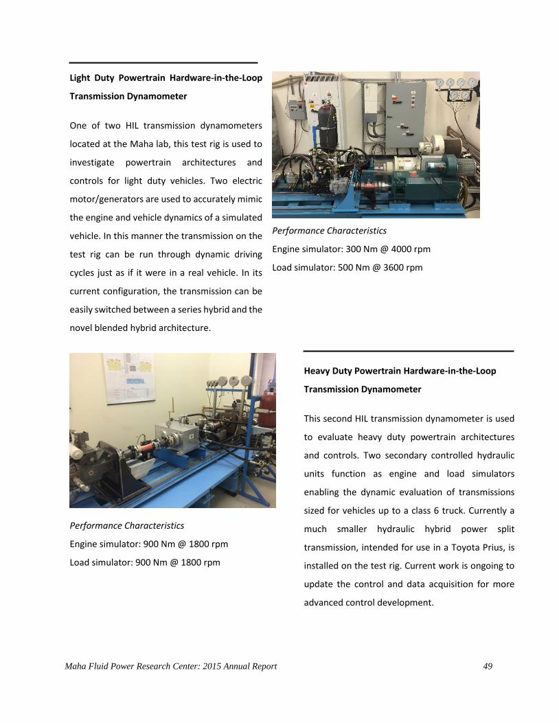
Light Duty Powertrain Hardware-in-the-Loop
Transmission Dynamometer
One of two HIL transmission dynamometers
located at the Maha lab, this test rig is used to
investigate powertrain architectures and
controls for light duty vehicles. Two electric
motor/generators are used to accurately mimic
the engine and vehicle dynamics of a simulated
vehicle. In this manner the transmission on the
test rig can be run through dynamic driving
cycles just as if it were in a real vehicle. In its
current configuration, the transmission can be
easily switched between a series hybrid and the
novel blended hybrid architecture.
Performance Characteristics
Engine simulator: 300 Nm @ 4000 rpm
Load simulator: 500 Nm @ 3600 rpm
Performance Characteristics
Engine simulator: 900 Nm @ 1800 rpm
Load simulator: 900 Nm @ 1800 rpm
Heavy Duty Powertrain Hardware-in-the-Loop
Transmission Dynamometer
This second HIL transmission dynamometer is used
to evaluate heavy duty powertrain architectures
and controls. Two secondary controlled hydraulic
units function as engine and load simulators
enabling the dynamic evaluation of transmissions
sized for vehicles up to a class 6 truck. Currently a
much smaller hydraulic hybrid power split
transmission, intended for use in a Toyota Prius, is
installed on the test rig. Current work is ongoing to
update the control and data acquisition for more
advanced control development.

Maha Fluid Power Research Center: 2015 Annual Report 50
Performance Characteristics
Max. Torque: 30000 Nm
Max. Pressure: 350 bar
Max. Power: 30 kW
Rotary Actuator
JIRA Test Rig
The joint integrated rotary actuator test rig (JIRA) was
originally built for the experimental investigation of
displacement controlled rotary actuators. The ideas and
technologies developed for and implemented in this
test rig have been utilized as end effector drives in
mobile robots and large manipulators as well as for
applications such as stabilizers in cars or ships.
Recent improvements on the test rig have allowed for
the demonstration of pump switching for the sequential
operation of multiple actuators. New control concepts
focused on actuator operability have been developed
and demonstrated that DC actuation can be utilized for
precise motion actuation. Finally, research is in progress
to investigate the application of high-frequency DC
actuation to be utilized on railway vibrators.
Cavitation/PIV test rig
This test rig was designed to visualize and conduct
Particle Image Velocimetry (PIV) analysis of
cavitation in hydraulic oil. This test rig was designed
in support of CCEFP project 3C and will support the
computational studies in modeling cavitation in
hydraulic components.
Maha Fluid Power Research Center: 2015 Annual Report 51
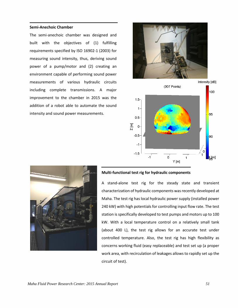
Semi-Anechoic Chamber
The semi-anechoic chamber was designed and
built with the objectives of (1) fulfilling
requirements specified by ISO 16902-1 (2003) for
measuring sound intensity, thus, deriving sound
power of a pump/motor and (2) creating an
environment capable of performing sound power
measurements of various hydraulic circuits
including complete transmissions. A major
improvement to the chamber in 2015 was the
addition of a robot able to automate the sound
intensity and sound power measurements.
Multi-functional test rig for hydraulic components
A stand-alone test rig for the steady state and transient
characterization of hydraulic components was recently developed at
Maha. The test rig has local hydraulic power supply (installed power
240 kW) with high potentials for controlling input flow rate. The test
station is specifically developed to test pumps and motors up to 100
kW. With a local temperature control on a relatively small tank
(about 400 L), the test rig allows for an accurate test under
controlled temperature. Also, the test rig has high flexibility as
concerns working fluid (easy replaceable) and test set up (a proper
work area, with recirculation of leakages allows to rapidly set up the
circuit of test).

Maha Fluid Power Research Center: 2015 Annual Report 52
Hydraulic Power Supply
The above test rigs are powered by a 320 kW central hydraulic power supply unit with a 2000 liter tank, a water
cooler and heating elements with five individually controlled pressure compensated pumps, 350 bar and 450
lpm output flow and a 60 l/min low pressure
installed in 2005. A second medium pressure
63 kW hydraulic power supply, with a
maximum flow rate of 250 l/min and pressure
differential of 60 bar, has also been added.
This supply is equipped with a 300 liter tank.
The central pressure net is mainly used to
supply hydraulic load units for the individual
test rigs, where the load units are based on
secondary control. The total installed electric
power amounts to 1200 kW.
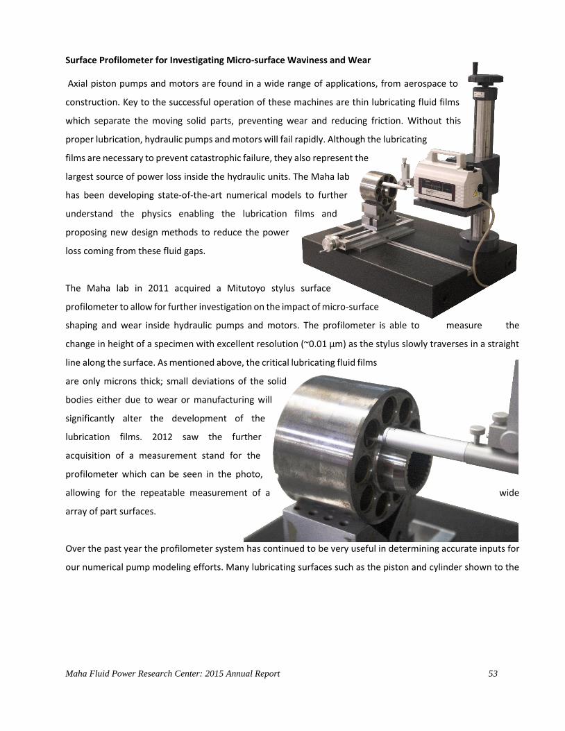
Maha Fluid Power Research Center: 2015 Annual Report 53
Surface Profilometer for Investigating Micro-surface Waviness and Wear
Axial piston pumps and motors are found in a wide range of applications, from aerospace to
construction. Key to the successful operation of these machines are thin lubricating fluid films
which separate the moving solid parts, preventing wear and reducing friction. Without this
proper lubrication, hydraulic pumps and motors will fail rapidly. Although the lubricating
films are necessary to prevent catastrophic failure, they also represent the
largest source of power loss inside the hydraulic units. The Maha lab
has been developing state-of-the-art numerical models to further
understand the physics enabling the lubrication films and
proposing new design methods to reduce the power
loss coming from these fluid gaps.
The Maha lab in 2011 acquired a Mitutoyo stylus surface
profilometer to allow for further investigation on the impact of micro-surface
shaping and wear inside hydraulic pumps and motors. The profilometer is able to measure the
change in height of a specimen with excellent resolution (~0.01 µm) as the stylus slowly traverses in a straight
line along the surface. As mentioned above, the critical lubricating fluid films
are only microns thick; small deviations of the solid
bodies either due to wear or manufacturing will
significantly alter the development of the
lubrication films. 2012 saw the further
acquisition of a measurement stand for the
profilometer which can be seen in the photo,
allowing for the repeatable measurement of a wide
array of part surfaces.
Over the past year the profilometer system has continued to be very useful in determining accurate inputs for
our numerical pump modeling efforts. Many lubricating surfaces such as the piston and cylinder shown to the
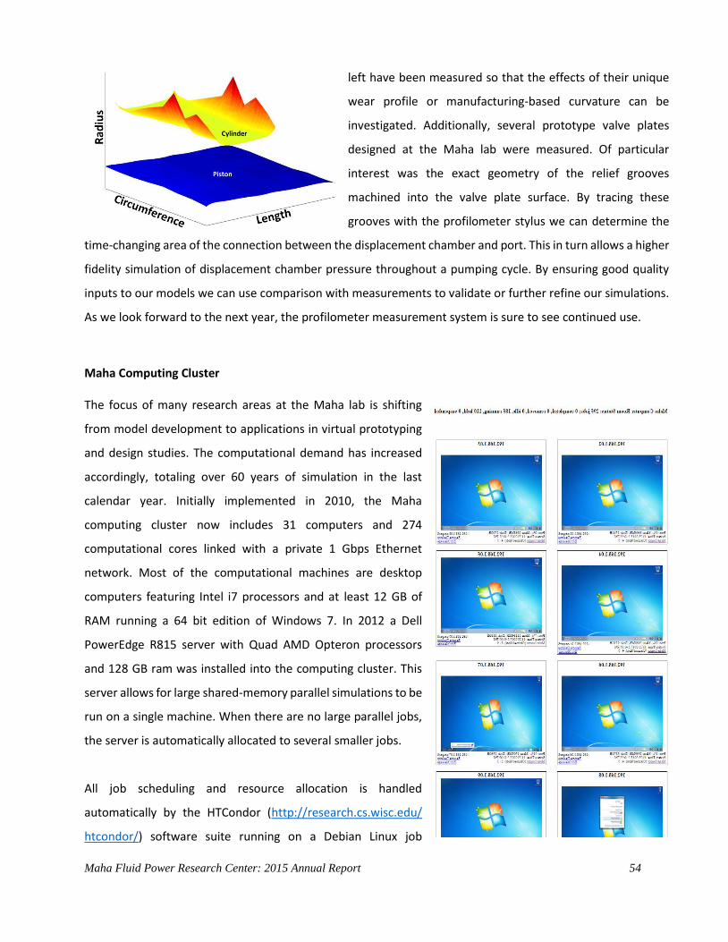
Maha Fluid Power Research Center: 2015 Annual Report 54
left have been measured so that the effects of their unique
wear profile or manufacturing-based curvature can be
investigated. Additionally, several prototype valve plates
designed at the Maha lab were measured. Of particular
interest was the exact geometry of the relief grooves
machined into the valve plate surface. By tracing these
grooves with the profilometer stylus we can determine the
time-changing area of the connection between the displacement chamber and port. This in turn allows a higher
fidelity simulation of displacement chamber pressure throughout a pumping cycle. By ensuring good quality
inputs to our models we can use comparison with measurements to validate or further refine our simulations.
As we look forward to the next year, the profilometer measurement system is sure to see continued use.
Maha Computing Cluster
The focus of many research areas at the Maha lab is shifting
from model development to applications in virtual prototyping
and design studies. The computational demand has increased
accordingly, totaling over 60 years of simulation in the last
calendar year. Initially implemented in 2010, the Maha
computing cluster now includes 31 computers and 274
computational cores linked with a private 1 Gbps Ethernet
network. Most of the computational machines are desktop
computers featuring Intel i7 processors and at least 12 GB of
RAM running a 64 bit edition of Windows 7. In 2012 a Dell
PowerEdge R815 server with Quad AMD Opteron processors
and 128 GB ram was installed into the computing cluster. This
server allows for large shared-memory parallel simulations to be
run on a single machine. When there are no large parallel jobs,
the server is automatically allocated to several smaller jobs.
All job scheduling and resource allocation is handled
automatically by the HTCondor (http://research.cs.wisc.edu/
htcondor/) software suite running on a Debian Linux job
Maha Fluid Power Research Center: 2015 Annual Report 55
scheduling server. Users log in to the job scheduling server to submit simulations to the cluster. Once
submitted, a job is assigned to a computer that has enough available processor cores and memory to
accommodate the job’s requirements. A single computer may simultaneously run multiple jobs. Once a job is
complete, it’s output and log files are returned to the job scheduling server where the user can retrieve them.
Certain jobs require user interaction during the course of the simulation. To accommodate these jobs, a user
may submit an interactive use reservation job through the HTCondor scheduler. Once a computer has been
allocated to the interactive use job, the user may establish a Remote Desktop connection with the computer.
The user can then transfer files directly and run any Windows compatible program.

Maha Fluid Power Research Center: 2015 Annual Report 56
Test Vehicles and Machines
In addition to the stationary test rigs, the Maha Fluid Power Research Center also houses several vehicles that
either have been used or are being used currently as platforms for demonstrating and/or investigating new
fluid power systems concepts.
Hydraulic Hybrid Demonstration Vehicle
A new addition for the Maha lab in 2015, this
hydraulic hybrid demonstration vehicle enables real
world testing of hybrid architectures and control
strategies. Especially valuable is the ability to explore
drivability and driver perception, a topic difficult to
investigate through either simulation or HIL testing.
Currently the demonstration vehicle can be operated
as either a conventional series hybrid, or the novel
blended hybrid, depending on a researcher’s needs.
Performance Characteristics
Engine: 142 kW gasoline
Unit 1: 100 cc/rev Units 2,3: 75 cc/rev
High pressure accumulator: 32 l
Maximum system pressure: 450 bar
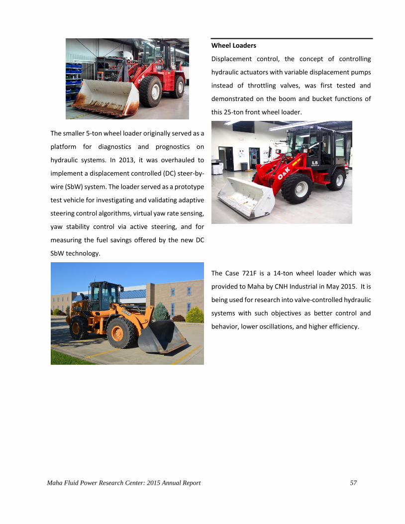
Maha Fluid Power Research Center: 2015 Annual Report 57
The smaller 5-ton wheel loader originally served as a
platform for diagnostics and prognostics on
hydraulic systems. In 2013, it was overhauled to
implement a displacement controlled (DC) steer-by-
wire (SbW) system. The loader served as a prototype
test vehicle for investigating and validating adaptive
steering control algorithms, virtual yaw rate sensing,
yaw stability control via active steering, and for
measuring the fuel savings offered by the new DC
SbW technology.
Wheel Loaders
Displacement control, the concept of controlling
hydraulic actuators with variable displacement pumps
instead of throttling valves, was first tested and
demonstrated on the boom and bucket functions of
this 25-ton front wheel loader.
The Case 721F is a 14-ton wheel loader which was
provided to Maha by CNH Industrial in May 2015. It is
being used for research into valve-controlled hydraulic
systems with such objectives as better control and
behavior, lower oscillations, and higher efficiency.

Maha Fluid Power Research Center: 2015Annual Report 58
Highly Efficient DC Hydraulic Hybrid Excavator Prototype
In 2015, efforts toward the advancement of the fluid power
technologies in the hydraulic hybrid excavator focused on
the development of supervisory-level algorithms. Two main
objectives were posed: 1) managing the newly
implemented hydraulics with pump switching and 2)
managing the hybrid architecture energy flows.
Pump switching is a novel idea that employs on/off valves (referred to a switching valves) to minimize the
installed pump power in displacement-controlled (DC) multi-actuator machines. This task is achieved
through the sequential use of actuators, which retains the inherent savings of DC actuation and maximizes
operability and performance. To manage DC actuation with pump switching, a supervisory controller that
makes use of operator commands and the total number of actuator combinations (given the excavator
architecture) was developed. A search algorithm is
employed to index a combination matrix containing the
commanded actuators and transmit these to the
corresponding switching valves and hydraulic units.
Ultimately, the combination of pump switching actuator
and supervisory-level control algorithms has led to more
efficient, reliable and better performing multi-actuator
systems with greatly improved operability.
Hydraulic hybrid architectures have increasingly gained recognition as
a highly efficient form of power transmission. For the excavator
prototype, the swing drive was equipped with a high pressure
accumulator and a swash-plate type over-center pump/motor
connected to the excavator ring gear. With the demonstration of
conventional drive operability, the task for 2015 was to efficiently
manage the power flows to demonstrate the possibility of engine
downsizing, thereby demonstrating further energy and fuel savings.
This task was accomplished and measurements on the excavator prototype showed that the engine could
be reduced by up to 45%. The algorithm, an energy-based feed-forward instantaneous optimization, takes
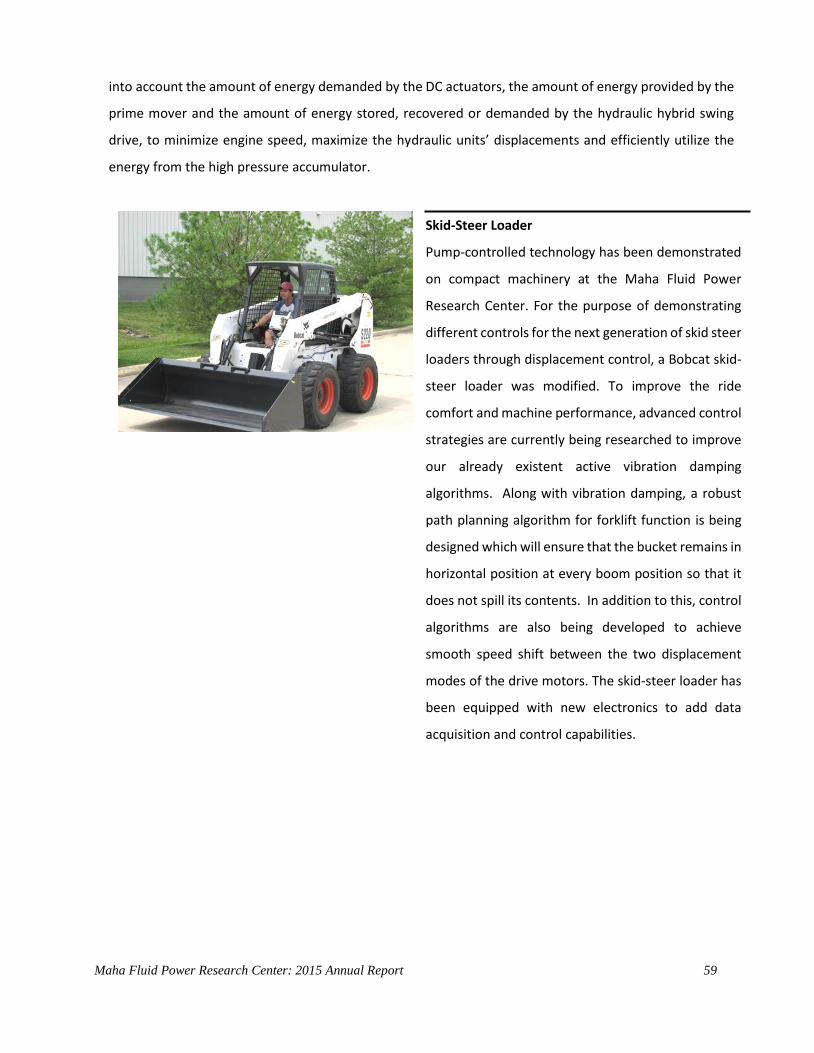
Maha Fluid Power Research Center: 2015 Annual Report 59
into account the amount of energy demanded by the DC actuators, the amount of energy provided by the
prime mover and the amount of energy stored, recovered or demanded by the hydraulic hybrid swing
drive, to minimize engine speed, maximize the hydraulic units’ displacements and efficiently utilize the
energy from the high pressure accumulator.
Skid-Steer Loader
Pump-controlled technology has been demonstrated
on compact machinery at the Maha Fluid Power
Research Center. For the purpose of demonstrating
different controls for the next generation of skid steer
loaders through displacement control, a Bobcat skid-
steer loader was modified. To improve the ride
comfort and machine performance, advanced control
strategies are currently being researched to improve
our already existent active vibration damping
algorithms. Along with vibration damping, a robust
path planning algorithm for forklift function is being
designed which will ensure that the bucket remains in
horizontal position at every boom position so that it
does not spill its contents. In addition to this, control
algorithms are also being developed to achieve
smooth speed shift between the two displacement
modes of the drive motors. The skid-steer loader has
been equipped with new electronics to add data
acquisition and control capabilities.
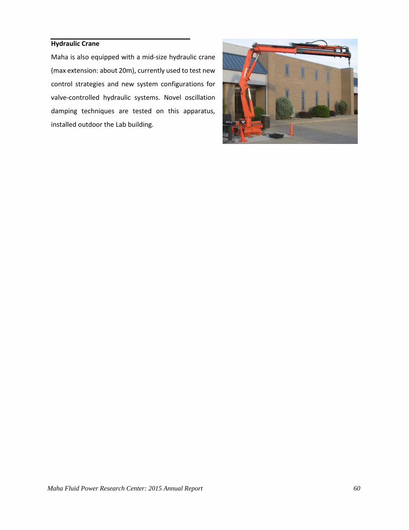
Maha Fluid Power Research Center: 2015 Annual Report 60
Hydraulic Crane
Maha is also equipped with a mid-size hydraulic crane
(max extension: about 20m), currently used to test new
control strategies and new system configurations for
valve-controlled hydraulic systems. Novel oscillation
damping techniques are tested on this apparatus,
installed outdoor the Lab building.
Maha Fluid Power Research Center: 2015 Annual Report 61
3 Research Grants
Total annual budget in 2014: $ 924,049
Federal sponsors:
Engineering Research Center – Center for Compact and Efficient Fluid Power.
Project 1F.1 (Variable Displacement Gear Machines): $109,504
USDA – AFRI (Agriculture and Food Research Initiative Competitive Grants Program) - New generation of
green, high efficient agricultural machines powered by high-pressure water hydraulic technology: $125,000
NSF – Accelerating Innovation Research
Project title: Novel Concept for Variable Delivery Flow Units for Fluid Power Applications $ 101,000
Purdue Maha Research funds: $45,000
Industry Sponsors: total $ 537,520
Other Sponsors:
Chainless Challenge (Parker Hannifin): $ 6,025

Maha Fluid Power Research Center: 2015 Annual Report 62
4 Publications, Invited Lectures, Patents, and Reports
Journal Articles
Pan J., Cheng Y., Vacca A., Yang J., 2015, Effect of Temperature on Grease Flow Properties in Pipes, Tribology
Transactions, DOI: 10.1080/10402004.2015.1093205
Opperwall, T., Vacca, A., 2015, Modeling Noise Sources and Propagation in Displacement Machines and
Hydraulic Lines, JFPS International Journal of Fluid Power System, Vol. 8 (2015) No. 1, pp. 30-37, selected
for journal publication from the 9th JFPS International Symposium on Fluid Power, Oct. 28-31, 2014,
Matsue, Japan
Altare, G., Vacca, A., 2015, A Design Solution for Efficient and Compact Electro-Hydraulic Actuators, Procedia
Engineering 106 ( 2015 ), 8 – 16
Cristofori D., Vacca A., 2015, Modeling Hydraulic Actuator Mechanical Dynamics from Pressure Measured at
Control Valve Ports, Journal of Systems and Control Engineering, July 2015, vol 229 n. 6.
Tang Q. , Chen J., Vacca A., 2015, Tribological Behaviors of Carbon Fiber Reinforced PEEK Sliding on Ion Nitrided
2Cr13 Steel Lubricated with Tap Water, Tribology Transactions, Vol. 58, Issue 4, 2015
Thiagarajan D., Dhar S., Vacca A., 2015, A Novel Fluid Structure Interaction-EHD Model and Optimization
Procedure for an Asymmetrical Axially Balanced External Gear Machine, Tribology Transactions, vol. 58,
issue 2, 2015
Dhar S., Vacca A., 2015, A Novel FSI-Thermal Coupled TEHD Model and Experimental Validation through Indirect
Film Thickness Measurements for the Lubricating Interface in External Gear Machines, Tribology
International, vol. 82 Part A, February 2015, pp. 162-175
Journal papers under review (at Dec. 2015): 4.

Maha Fluid Power Research Center: 2015 Annual Report 63
Conference Proceedings
Pellegri M., Vacca A., 2015, A CFD-Radial Motion Coupled Model for the Evaluation of the Features of Journal
Bearings in External Gear Machines, ASME/Bath 2015 Symposium on Fluid Power and Motion Control, Oct
12-14, 2015, Chicago, IL, USA
Bianchi R., Ritelli G.F., Vacca A., Ruggeri M., 2015, A Frequency-Based Methodology for the Reduction of
Payload Oscillations in Hydraulic Load Handling Machines, ASME/Bath 2015 Symposium on Fluid Power
and Motion Control, Oct 12-14, 2015, Chicago, IL, USA
Opperwall T., Vacca A., 2015, A Transfer Path Approach for Experimentally Determining the Noise Impact of
Hydraulic Components, SAE 2015 Commercial Vehicle Engineering Congress (COMVEC), Oct 6-8 2015,
Rosemont, IL, USA. SAE paper 2015-01-2854
Devendran R.S., Vacca, A., 2015, A Novel Concept for a Variable Delivery External Gear Machine, SICFP2015
14th Scandinavian International Conference on Fluid Power, May 20-22, 2015, Tampere, Finland
Invited Talks/Lectures
Invited talk – Dr. Vacca - “Modeling and Optimization of Positive Displacement Pumps for High Pressure Fluid
Power Applications”, ModeFrontier North America Users Meeting, 5th Nov 2015, Novi, MI
Invited seminar - Dr. Vacca - on “Understanding the key of positive displacement machines: the internal
lubricating gaps”, Dipartimento di Ingegneria Industriale, University of Napoli “Federico II” March
19, 2015
Invited lectures – Dr. Vacca - (4 hrs) on “Pumps and Motors for Fluid Power Applications” to mechanical
engineering student (master level), University of Napoli “Federico II”, March 23-25, 2015
Patents Filed
Vacca, A. and Devendran, R.S., Purdue Research Foundation. 2015. Variable Displacement External Gear
Machine. 2014-VACC-66716
Maha Fluid Power Research Center: 2015 Annual Report 64
5 Theses Completed In 2015
PhD Theses
Ram Sudarsan Devendran 2015. An Innovative Working Concept for Variable Delivery Flow External Gear
Machine. PhD thesis, Purdue University.
Timothy Opperwall 2015. Numerical Modeling and Experimental Investigation of Noise Generation in
External Gear Pumps. PhD thesis, Purdue University.
Master’s Theses
Sidhant Gulati 2015. A Generic Design Procedure to Determine the Optimal Profile of Porting Grooves in
External Gear Machines. Master’s thesis, Purdue University.

Maha Fluid Power Research Center: 2015 Annual Report 65
6 Educational Activities
6.1 Courses Taught at Purdue
Andrea Vacca is instructor of following courses at Purdue:
ABE 210 – Thermodynamic Principles of Engineering and Biological Systems
ME 309 – Fluid Mechanics
ME 435 – Hydraulic Control Systems
ABE 210 – Thermodynamic Principles of Engineering and Biological Systems Brief Course Description: 1 Semester, 2 Lectures/week, 3 Credits
The objective of this course is to provide students background on the application of thermodynamic
principles in the design and operation of biological and engineering systems. Specifically the course will focus
on the first and second laws of thermodynamics and on the applications of these laws to biological and
mechanical/agricultural engineering systems.
Specific systems include power cycles, refrigeration cycles, and energy conservation systems.
Emphasis will be placed on developing a mastery of the basic concepts and problem solving skills.
The successful completion of the course will enable the student to:
1. understand basic principles of material, energy, and entropy balances;
2. understand applications of energy and entropy balances to power, refrigeration, and biological systems;
3. apply basic thermodynamic concepts/functions to the design of systems.
Textbook: Thermodynamics: an engineering approach (7th ed.) by Y.A. Cengel and M.A. Boles. McGraw-Hill
(2010).
Course notes: All lecture notes are available through Purdue Blackboard Learn
Lab: Four lab experiences on 1st and 2nd Laws of Thermodynamics as well as on power cycles were
developed by Dr. Vacca
Exams/Final project: two midterm exams and a final exam

Maha Fluid Power Research Center: 2015 Annual Report 66
ME 309 – Fluid Mechanics Brief Course Description: 1 Semester, 3 Lectures/week, 4 Credits
Course objectives:
1. Develop the ability to identify and classify the various types of flows one may encounter.
2. Develop (from first principles) the control volume formulation of the basic laws with emphasis on
conservation of mass and Newton’s 2nd law.
3. Apply the control volume formulation of the basic laws to model physical systems.
4. Conduct simple experiments and analyze data.
5. Enhance systematic problem solving skills and sharpen written communication skills through short
technical laboratory reports.
Textbook: Pritchard, P.J, Fox and McDonald’s Introduction to Fluid Mechanics, 8th ed., Wiley & Sons
Course notes: All lecture notes are available through Purdue Blackboard Learn
Lab: Eight labs on basic equations of fluid mechanics
Exams/Final project: two midterm exams and a final exam
ABE 435 – Hydraulic Control Systems Brief Course Description:
1 Semester, 2 Lectures/week, 4 Credits
Course Objectives
This class provides the student with the basics of fluid power technology. After introducing the standard of
representation of hydraulic systems and components, in the first part of the class the operation of basic
components such as pumps, motors, cylinders, hydraulic control valves, filters and accumulators will be
detailed.
The second part of the class provides the basics for analyzing and designing completer hydraulic control
systems for both the case of single and multiple user. A particular emphasis will be given to the challenges of
meeting functional requirements minimizing both cost and fuel consumption. Starting from basilar circuits,
the lectures and labs will cover current state of art systems for mobile applications.
The course is divided into class lectures and labs. During the lab experiences, the students will learn how to
assemble and troubleshoot hydraulic circuits and how to simulate the operation of a hydraulic system. The
numerical modeling of hydraulic systems will be performed with the commercial software AMESim.

Maha Fluid Power Research Center: 2015 Annual Report 67
After completion of the course, the student will be capable of:
1. Understanding and design hydraulic systems according to ISO standard
2. Understand the principle of operation of basic hydraulic components such as pumps, motors,
hydraulic control valves, pipes, linear actuators (cylinders)
3. Design basic hydraulic control circuits with the components specified above.
4. Analyze the operation of a hydraulic circuit through both analytical and numerical approaches.
5. Test the functioning of hydraulic components and systems.
6. Troubleshoot hydraulic mobile equipment malfunctions.
7. Understand and design the hydraulic systems of mobile machinery, including hydrostatic
transmissions, load sensing and power steering systems.
Textbook: N/A
Course notes: All lecture notes are available through Purdue Blackboard Learn
Lab: Ten labs on numerical simulation (AMESim) and on basic hydraulic control systems
Exams/Final project: two midterm exams and a final project on a complete hydraulic system
6.2 CCEFP REU Bootcamp
As faculty member of the CCEFP (Center for Compact and Efficient Fluid Power), Andrea Vacca volunteered for
organizing the 2015 edition of the CCEFP Bootocamp at the Maha Fluid Power Research Center, an outreach
activity of CCEFP. The 2015 CCEFP Fluid Power REU Bootcamp, was held at Purdue University on May 26-29,
2015. The NSF's Research Experiences for Undergraduates (REU) program is designed to encourage STEM
students to continue their learning in graduate school settings by providing opportunities for summer
experience in a university research lab. The CCEFP is actively involved in this program and hosted nearly 20 REU
students from its 7 member universities (Georgia Tech, University of Illinois in Urbana-Champaign, University
of Minnesota, Milwaukee School of Engineering, North Carolina A&T State University, Purdue University, and
Vanderbilt University) in a boot camp style introduction to fluid power topics.

Maha Fluid Power Research Center: 2015 Annual Report 68
This year's boot camp was a two day introduction to the principles of fluid power technology through various
lectures, hands-on activities, and tours of some of Purdue University's research laboratories. The students were
welcomed by Prof. Monika Ivantysynova followed by an introduction lecture on fluid power by Prof. Andrea
Vacca. The students then attended the following lectures / demonstrations:
- "Water Hydraulic Test Rig" prepared by Guido Francesco Ritelli
- "Hydraulic Circuit Construction and Debugging" prepared by Tim Opperwall
- "Pump Displacement Controlled Actuation Technology" prepared by Enrique Busquets
- "Hydraulic Pumps and Motors" prepared by Ashley Wondergem and Lizhi Shang
The boot camp was also a great networking opportunity for the participants to meet other students and faculty
members in the Center.
Pictures from the 2015 Fluid Power Bootcamp
More About CCEFP
The Center for Compact and Efficient Fluid Power (CCEFP) is a network of researchers, educators, students and
industry working together to transform the fluid power industry—how it is researched, applied and studied.
Center research is creating hydraulic and pneumatic technology that is compact, efficient, and effective. The
CCEFP’s education and outreach program is designed to transfer this knowledge to diverse audiences—
students of all ages, users of fluid power and the general public.
The CCEFP is a National Science Foundation Engineering Research Center, established in June 2006. In addition
to its grant from NSF, the Center is supported by its seven participating universities and more than 50 industrial
partners.
Maha Fluid Power Research Center: 2015 Annual Report 69
Purdue University is one of the seven universities represented in the CCEFP. The other participating universities
are the Georgia Institute of Technology, the University of Illinois at Urbana-Champaign, the University of
Minnesota, Milwaukee School of Engineering, North Carolina A&T State University, and Vanderbilt University.
More information about the activities of CCEFP are online (www.ccefp.org)
Dr. Andrea Vacca lead the two projects: Project 1F.1: Variable Displacement External Gear Machine; and Project
3B.3 Oscillation Damping in Hydraulic Machines.
6.3 Chainless Challenge
This project is aimed to formulate a viable and economically feasible solution for the next generation of human
powered green energy vehicles. In particular, the study explores technologies for hydrostatic transmissions
which can be used in place of the typical chain system used for power transmission in common bicycles.
Although its lower energy transmission efficiency, compared to the pure mechanical chain, the use of a
hydraulic system offers opportunities for energy management for more comfortable pedaling as well as for
energy recovery in passive phases, such as braking.
Within this project, every year a team of Purdue students supervised by Dr. Vacca design and realize an
hydraulic vehicle to compete to the Parker Chainless Challenge. Several US universities (Univ. of Minnesota,
Univ. of Illinois at Urbana Champaign, California Polytechnic State Univ., Western Michigan Univ, etc.) take part
to this event, presenting every year innovative solutions in accordance to the rules of the competition,
established by the main Sponsor (Parker Hannifin).
The final competition, usually held in California during April, is based on different challenges between
participants which include a sprint test of 400 m, an efficiency test (performance of the vehicle without human
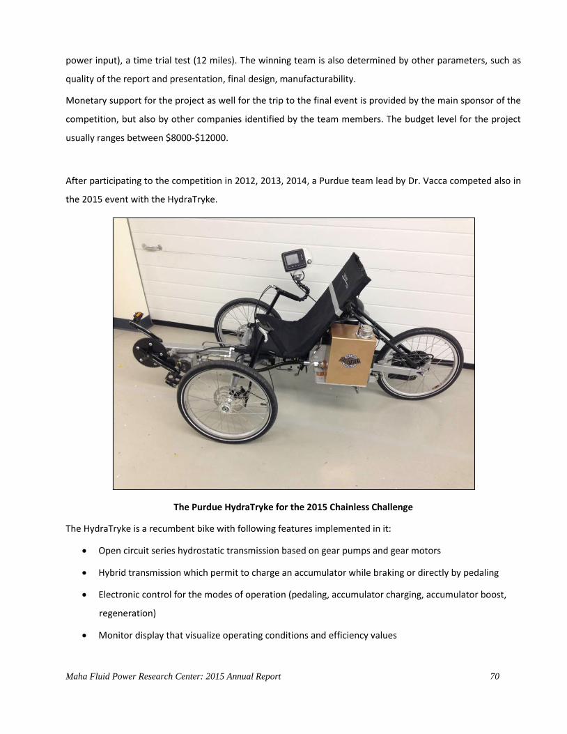
Maha Fluid Power Research Center: 2015 Annual Report 70
power input), a time trial test (12 miles). The winning team is also determined by other parameters, such as
quality of the report and presentation, final design, manufacturability.
Monetary support for the project as well for the trip to the final event is provided by the main sponsor of the
competition, but also by other companies identified by the team members. The budget level for the project
usually ranges between $8000-$12000.
After participating to the competition in 2012, 2013, 2014, a Purdue team lead by Dr. Vacca competed also in
the 2015 event with the HydraTryke.
The Purdue HydraTryke for the 2015 Chainless Challenge
The HydraTryke is a recumbent bike with following features implemented in it:
Open circuit series hydrostatic transmission based on gear pumps and gear motors
Hybrid transmission which permit to charge an accumulator while braking or directly by pedaling
Electronic control for the modes of operation (pedaling, accumulator charging, accumulator boost,
regeneration)
Monitor display that visualize operating conditions and efficiency values

Maha Fluid Power Research Center: 2015 Annual Report 71
Integration with a heart-bit rate sensor to monitor driver‘s status
The hydraulic circuit of the bike is schematized below.
The hydraulic circuit of the Purdue HydraTryke
At the final event (April 2015 at Irvine, CA), the bike experienced a failure of the hydraulic motor. Despite this
inconvenience, the team received the 1st award for Uniqueness of Design/Originality and the 2nd award for
Manufacturability/Workmanship.
6.4 Test stands for education in Fluid Power
Dr. Vacca’s commitment into education of fluid power technology also involves the creation of original ways to
demonstrate basic concepts of fluid power. Within this effort, in 2015 his team created an original test
apparatus suitable to demonstrate the features of modern Load Sensing (LS) architectures for hydraulic
machines. Load Sensing systems are in use in several applications, especially in the mobile fluid power field.
However, basic tests demonstrator suitable for student lab experiences are usually not available in academic
fluid power labs. The apparatus designed and developed at the Maha permits to fill the typical gap of both
introductory and advances fluid power classes, which usually cover theory of LS systems but very seldom with
practical demonstration through hands-on experiences, in which the controllability and energy features of the
systems can be quantified.
After its conception and initial tests at Maha, the apparatus was installed in the Fluid Power Lab of the
Agricultural and Biological Engineering Dept. of Purdue University, and it has been used for lab experiences
within educational courses starting from Fall 2015 (ABE435 – Hydraulic Control Systems).

Maha Fluid Power Research Center: 2015 Annual Report 72
CAD drawing of the LS test-stand
With the layout shown in the figure above, the system permits the students to:
a) Learn the basic principle of operation of load sensing systems;
b) Learn the concept of control of hydraulic actuators through independent metering;
c) Understand the concepts behind pre-compensated and post-compensated LS system architectures;
d) Be able to quantify the energy consumption of the system as a function of the load unbalance of the
different users;
e) Quantify the energy consumption of the system and the system efficiency for steady operating
conditions and for specific drive cycles;
f) Understand the concept of flow saturation and pressure saturation;
g) Understand the strategies for realizing flow sharing under flow saturation conditions;
As it can be noticed from the Figure below, the system consists of two hydraulic cylinders (users) connected to
the hydraulic power supply by means of a LS hydraulic valve block. For the valve block, two options will be
available: a pre-compensated and a post compensated valve block. It is important to notice how both valve
blocks implements the independent metering control strategy. In this way, the apparatus will permit to show
not only the typical features of a LS system, but also those of the emergent independent metering control.
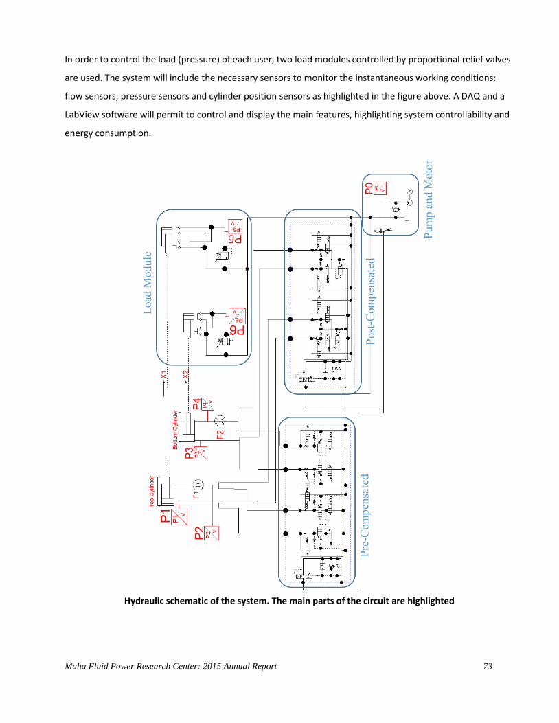
Maha Fluid Power Research Center: 2015 Annual Report 73
In order to control the load (pressure) of each user, two load modules controlled by proportional relief valves
are used. The system will include the necessary sensors to monitor the instantaneous working conditions:
flow sensors, pressure sensors and cylinder position sensors as highlighted in the figure above. A DAQ and a
LabView software will permit to control and display the main features, highlighting system controllability and
energy consumption.
Hydraulic schematic of the system. The main parts of the circuit are highlighted

Maha Fluid Power Research Center: 2015 Annual Report 74
During 2015, three undergraduate students and two graduate students under Dr. Vacca’s supervision
contributed to the design of the system. It is expected that the system will be used for educational purposes
by more than 50 students per year.
The NFPA (National Fluid Power Association – Technology foundation) contribution, through the project
“Educational Test Station for Multi-Users Load-Sensing System Architectures”, was instrumental for the
realization of the apparatus, in particular as concerns the physical structure, the sensors, tubing and fittings.
Instrumental was the contribution of following industrial sponsors:
- Hydraforce: donation of all valves, including the independent metering LS valve blocks;
- Concentric: donation of the hydraulic power pack;
- Parker Hannifin: donation of the pressure sensors
Purdue Agricultural and Biological Engineering Dept also contributed to this project, providing funding
specifically dedicated to the improvement of educational labs at Purdue.
Image of the test stand for experiments and demonstration on Load Sensing Systems

Maha Fluid Power Research Center: 2015 Annual Report 75
7 International and National Conferences Attended
The 14th Scandinavian International Conference on Fluid Power (SICFP2015)
May 20-22, 2015. Tampere Finland.
Attendees:
Andrea Vacca (session chair; paper presentation)
SAE 2015 Commercial Vehicle Engineering Congress (ComVec)
October 6-8, 2015. Rosemont, IL, USA.
Attendees:
Timothy Opperwall (paper Presentation)
ASME/BATH 2015 Symposium on Fluid Power & Motion Control (FPMC15)
October 12-14, 2015. Chicago, IL, USA.
Attendees:
Andrea Vacca (member of the organizing committee; editorial and publication co-chair)
Matteo Pellegri (Paper Presentation)
Riccardo Bianchi (Paper Presentation)

Maha Fluid Power Research Center: 2015 Annual Report 76
Fluid Power Innovation & Research Conference 2015 (FPIRC 15) October 13-16, 2015. Chicago, IL, USA.
Attendees:
Andrea Vacca (Session chair; Paper presentation)
Divya Thiagarajan (Paper Presentation)
Timothy Opperwall (Paper Presentation)
Gautham Ramchandran (Paper Presentation)
Esteco ModeFrontier North America User Meeting 2015 (UM 15) November 4-5, 2015. Novi, MI, USA.
Attendees:
Andrea Vacca (Invited presentation)
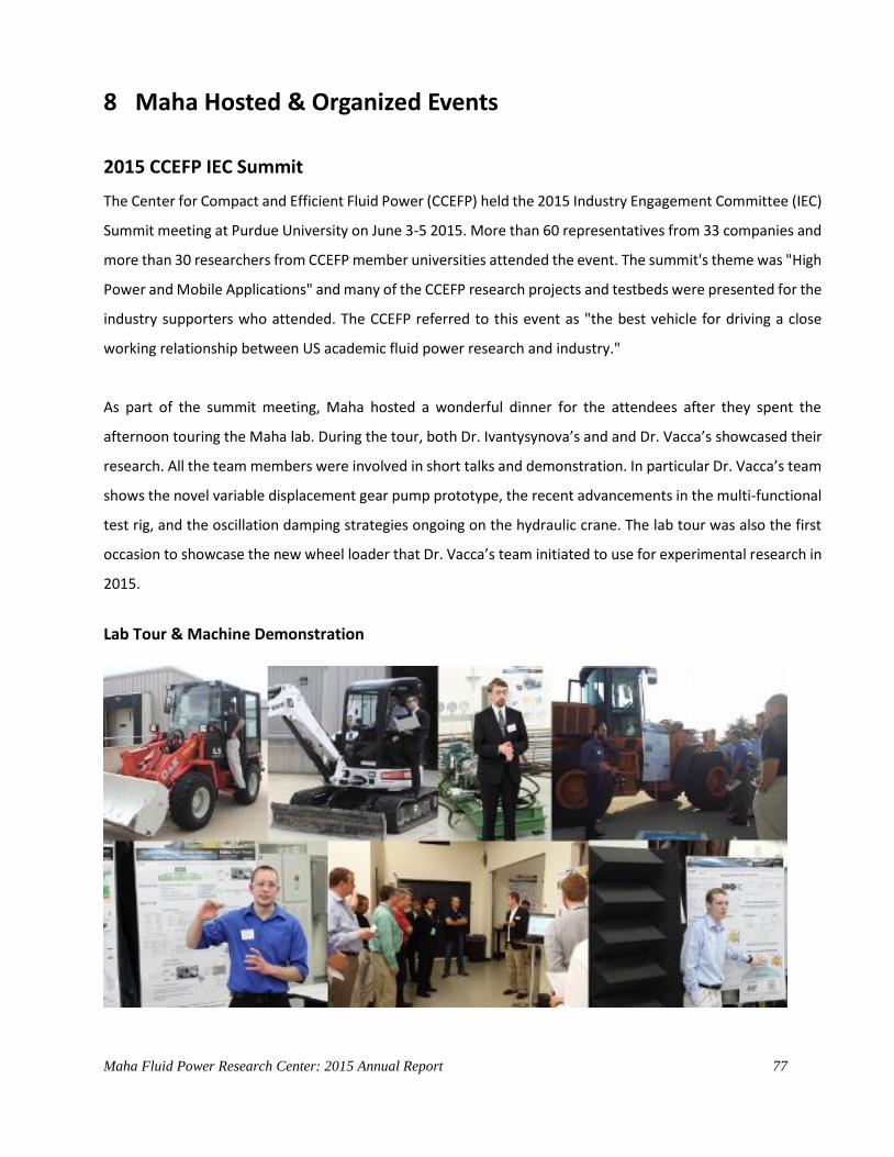
Maha Fluid Power Research Center: 2015 Annual Report 77
8 Maha Hosted & Organized Events
2015 CCEFP IEC Summit
The Center for Compact and Efficient Fluid Power (CCEFP) held the 2015 Industry Engagement Committee (IEC)
Summit meeting at Purdue University on June 3-5 2015. More than 60 representatives from 33 companies and
more than 30 researchers from CCEFP member universities attended the event. The summit's theme was "High
Power and Mobile Applications" and many of the CCEFP research projects and testbeds were presented for the
industry supporters who attended. The CCEFP referred to this event as "the best vehicle for driving a close
working relationship between US academic fluid power research and industry."
As part of the summit meeting, Maha hosted a wonderful dinner for the attendees after they spent the
afternoon touring the Maha lab. During the tour, both Dr. Ivantysynova’s and and Dr. Vacca’s showcased their
research. All the team members were involved in short talks and demonstration. In particular Dr. Vacca’s team
shows the novel variable displacement gear pump prototype, the recent advancements in the multi-functional
test rig, and the oscillation damping strategies ongoing on the hydraulic crane. The lab tour was also the first
occasion to showcase the new wheel loader that Dr. Vacca’s team initiated to use for experimental research in
2015.
Lab Tour & Machine Demonstration
Maha Fluid Power Research Center: 2015 Annual Report 78
9 Maha Social Events
Life in the Maha lab is not always about work. Occasionally we are able to get together and enjoy
each other’s company. Below are some highlights of the past year.
Summer party at Susan’s house
Andrea’s house parties
Maha Fluid Power Research Center: 2015 Annual Report 79
Celebrating successful PhD defenses
Ram’s defense
Tim’s defense
Maha Fluid Power Research Center: 2015 Annual Report 80
Guido’s defense

Maha Fluid Power Research Center: 2015 Annual Report 81
10 Maha Team in 2015
Maha Faculty
Dr. Andrea Vacca
Associate Professor
Joint Appointment in ABE/ME
Phone: (765) 430-0081
Origin: Italy
March 2010-present
Andrea Vacca – Short Bio
In 1999 Andrea Vacca earned his Master's degree - with honors - in Mechanical Engineering from the
University of Parma (Italy) and his doctorate in Energy Systems from the University of Florence (Italy) in
2005. For both degrees he presented theses in the field of Heat Transfer and Gas Turbine Blade Cooling
Technology. Before joining Purdue University as Assistant Professor in 2010, Prof. Vacca was Assistant
Professor of Fluid Machinery at the University of Parma (Italy).
In 2014, he was promoted to the role of Associate Professor, with joint appointment between Purdue
Agricultural and Biological Engineering and Purdue Mechanical Engineering.
Prior to his arrival to Purdue, Prof. Vacca participated in various research activities related to the fields of
internal combustion engines, food technology and hydraulic systems.
Fluid power technology has been Prof. Vacca's major research interest since 2002. Particular goals of his
research are the improvement of energy efficiency and controllability of fluid power systems and the
reduction of noise emissions of fluid power components. To accomplish the goals of his research, his
research team has developed original numerical and experimental techniques to simulate fluid power
systems and components, especially for gear machines and hydraulic control valves. Prof. Vacca's interests
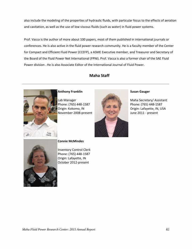
Maha Fluid Power Research Center: 2015 Annual Report 82
also include the modeling of the properties of hydraulic fluids, with particular focus to the effects of aeration
and cavitation, as well as the use of low viscous fluids (such as water) in fluid power systems.
Prof. Vacca is the author of more about 100 papers, most of them published in international journals or
conferences. He is also active in the fluid power research community. He is a faculty member of the Center
for Compact and Efficient Fluid Power (CCEFP), a ASME Executive member, and Treasurer and Secretary of
the Board of the Fluid Power Net International (FPNI). Prof. Vacca is also a former chair of the SAE Fluid
Power division . He is also Associate Editor of the International Journal of Fluid Power.
Maha Staff
Anthony Franklin
Lab Manager Phone: (765) 448-1587 Origin: Kokomo, IN November 2008-present
Susan Gauger
Maha Secretary/ Assistant Phone: (765) 448-1587 Origin: Lafayette, IN, USA June 2011 - present
Connie McMindes
Inventory Control Clerk Phone: (765) 448-1587 Origin: Lafayette, IN October 2012-present

Maha Fluid Power Research Center: 2015 Annual Report 83
Maha Graduate Students

Maha Fluid Power Research Center: 2015 Annual Report 84
Maha Fluid Power Research Center: 2015 Annual Report 85
Visiting Scholars
Maha Fluid Power Research Center: 2015 Annual Report 86
Undergraduate students